particle simulation of radio frequency waves in fusion … · particle simulation of radio...
TRANSCRIPT

1 TH/P2-10
Particle Simulation of Radio Frequency Waves in Fusion Plasmas Animesh Kuley, 1 Jian Bao, 2,1 Zhixuan Wang, 1 Zhihong Lin, 1 Zhixin Lu, 3 and Frank Wessel4
1Department of Physics and Astronomy, University of California, Irvine, California-92697, USA 2Fusion simulation center, Peking University, Beijing 100871, China
3 Center for Momentum Transport and Flow Organization, UCSD, La Jolla, CA-92093, USA 4 Tri Alpha Energy, Inc., Post Office Box 7010, Rancho Santa Margarita, California-92688, USA
E-mail: [email protected]
Abstract. Global particle in cell simulation model in toroidal geometry has been developed for the first time to provide a first principle tool to study the radio frequency (RF) nonlinear interactions with plasmas. In this model, ions are considered as fully kinetic ion (FKi) particles using the Vlasov equation and electrons are treated as guiding centers using the drift kinetic (DKe) equation. FKi/DKe is suitable for the intermediate frequency range, between electron and ion cyclotron frequencies. This model has been successfully implemented in the gyrokinetic toroidal code (GTC) using realistic toroidal geometry with real electron-to-ion mass ratio. To verify this simulation model, we first use an artificial antenna to verify the linear mode structure and frequencies of electrostatic normal modes including ion plasma oscillation, ion Bernstein wave, lower hybrid wave, and electromagnetic modes and fast wave and slow wave in the cylindrical geometry. We then verify the linear propagation of lower hybrid waves in cylindrical and toroidal geometry. Because of the poloidal symmetry in the cylindrical geometry, the wave packet forms a standing wave in the radial direction. However, in the toroidal geometry, the waves propagate as two counter propagating waves in the poloidal direction due to the poloidal asymmetry of the magnetic field. The wave packet propagates faster in high field side compare to the low field side. This feature has been verified by the Wentzel–Kramers–Brillouin (WKB) solution. Electromagnetic mode conversions are observed in toroidal geometry, slow waves are launched at the plasma boundary and converts to fast waves at the mode conversion layer, which is consistent with linear theory. The nonlinear GTC simulation of the lower hybrid wave shows that the amplitude of the electrostatic potential is oscillatory due to the trapping of resonant electrons by the electric field of the lower hybrid wave. The nonlinear bounce frequencies have been verified with the analytic results. For comparison, in linear simulation the lower hybrid wave decays exponentially due to linear Landau damping.
1. Introduction
The importance of the radio frequency (RF) waves for the steady state operation of fusion experiments has been recognized from the early days of tokamak research and for the future burning plasma experiment ITER [1-3]. In ITER, RF waves will be used to provide sufficient central heating to access H mode, and to provide an off axis current drive for the current profile control. Furthermore, they will be used for the control of destructive magnetohydrodynamic instabilities (i.e., resistive wall modes). For the effective use of RF power, we need a better understanding of the key physics of RF waves in plasmas, e.g., nonlinear wave particle interaction and mode conversion.
Eigenvalue solvers have been widely used to study linear wave particle interaction in fusion plasmas. However, this method does not capture the crucial nonlinear physics. The initial value simulation model, in which a kinetic equation is integrated in time, can retain all the nonlinearities. Here, we develop a nonlinear particle simulation model for the waves in the intermediate frequency range, between the electron and ion cyclotron frequencies. Our simulation model uses fully kinetic ion (FKi), but treats the electron in the drift kinetic (DKe) limit. This simulation enables nonlinear simulation with real electron-to-ion mass ratio and has been successfully implemented in the gyrokinetic toroidal code (GTC) [4] with realistic toroidal geometry. Our goal is to address the nonlinear physics
2 TH/P2-10
associated with the RF heating and current drive using ion cyclotron waves and lower hybrid waves [5].
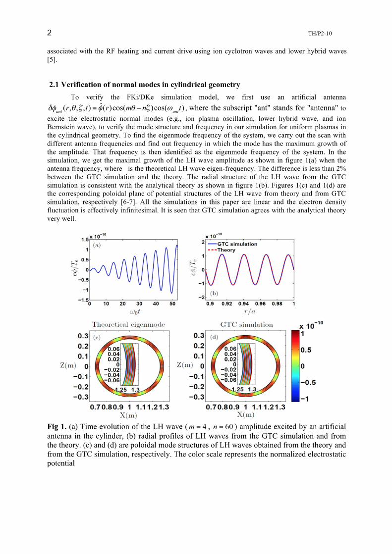
2.1 Verification of normal modes in cylindrical geometry To verify the FKi/DKe simulation model, we first use an artificial antenna δφant (r,θ ,ζ ,t) = φ̂(r)cos(mθ − nζ )cos(ωantt) , where the subscript "ant" stands for "antenna" to excite the electrostatic normal modes (e.g., ion plasma oscillation, lower hybrid wave, and ion Bernstein wave), to verify the mode structure and frequency in our simulation for uniform plasmas in the cylindrical geometry. To find the eigenmode frequency of the system, we carry out the scan with different antenna frequencies and find out frequency in which the mode has the maximum growth of the amplitude. That frequency is then identified as the eigenmode frequency of the system. In the simulation, we get the maximal growth of the LH wave amplitude as shown in figure 1(a) when the antenna frequency, where is the theoretical LH wave eigen-frequency. The difference is less than 2% between the GTC simulation and the theory. The radial structure of the LH wave from the GTC simulation is consistent with the analytical theory as shown in figure 1(b). Figures 1(c) and 1(d) are the corresponding poloidal plane of potential structures of the LH wave from theory and from GTC simulation, respectively [6-7]. All the simulations in this paper are linear and the electron density fluctuation is effectively infinitesimal. It is seen that GTC simulation agrees with the analytical theory very well.
Fig 1. (a) Time evolution of the LH wave ( 4m = , 60n = ) amplitude excited by an artificial antenna in the cylinder, (b) radial profiles of LH waves from the GTC simulation and from the theory. (c) and (d) are poloidal mode structures of LH waves obtained from the theory and from the GTC simulation, respectively. The color scale represents the normalized electrostatic potential

3 TH/P2-10
For verifying the GTC simulation of the electron Landau damping, we focus on the verification of the linear electron Landau damping of a single mode in the cylindrical geometry. We choose the mode number randomly; this has no physical meaning with regard to the real experiments. Other values of mode numbers can also give the results in agreement
Fig. 2 Comparison of ion Bernstein wave dispersion relation between the analytical theory and GTC simulation
with theory when ||k k⊥<< is satisfied. The simulation of the ( 4m = , 100n = ) LH wave with
|| 30.0k a = , 448.8k a⊥ = , 0.51pe ceω ω= , 0 3.72 LHω ω= , 0 6.67i ik vξ ω⊥ ⊥= = and
|| 0 || 2.33e ek vξ ω= = is performed in the cylinder ( 0.3a m= and 1.0R m= ). The time evolution of the electrostatic potential φ of the LH wave in the simulation and a numerical fitting are shown in figure 3(a). The fitting function is defined as ( ) ( )cos tt A t eγφ ω α= + , where ω , γ and α are the real frequency, damping rate, and initial phase of the LH wave, respectively. The damping rates obtained from the theory 0.18ana LHγ ω= − and the simulation
Figure 3. (a) Time history of the LH wave amplitude in the simulation. The dashed line is the numerical fitting. (b) Comparison of damping rates of LH waves obtained from the GTC simulation and the theoretical calculation in different regimes. (c) and (d) are the convergences of the number of particles per cell for LH wave frequency and damping rate, respectively.

4 TH/P2-10
0.18simu LHγ ω= − are the same. Then we carry out the simulations with 0.51pe ceω ω= in different ||eξ regimes, and compare simulation results of the damping rates with the theoretical calculation as shown in figure 3(b). Convergence tests indicate that 20 particles per cell are enough to simulate the linear electron Landau damping as shown in figures 3(c-d)
2.2 LH wave propagation
To further verify the FKi/DKe simulation model, we study the linear propagation of the lower hybrid wave in both cylindrical and toroidal geometry. We apply an antenna as a source of wave packets at the outer boundary of the simulation domain. Due to the poloidal symmetry of the magnetic field in the cylindrical geometry, the wave packets propagate back and forth between the inner and outer radial boundaries and form a standing wave. On the other hand, in the toroidal geometry, the poloidal harmonic number m is not a constant, due to the poloidal asymmetry of the magnetic field. The poloidal position of the wave packet changes during its propagation. In our simulation the launched wave packet that is initially a standing wave pattern has both positive and negative parallel wave vectors. Thus the lower hybrid waves propagate in clockwise and anticlockwise directions as two counter propagating waves. The coupling of different poloidal harmonics leads to a mode structure with poloidal asymmetry. When the lower hybrid wave propagates along the poloidal angle, the wave moves faster in the high-field side compared to the low-field side. To verify the simulation results, we have carried out the WKB calculation, which demonstrate that the radial and poloidal group velocity is indeed faster in the high field side than the low field side [7-8].
Figure 4. (a) WKB simulation of the ray trajectories is compared to GTC simulation in the toroidal geometry. (b)-(d) are the evolutions of the m number, radial group velocity and the poloidal group velocity of the ray, respectively. The blue solid line represents the ray in the high field side, and the black dash line represents the ray in the low field side.
3 Electromagnetic simulation of LH wave 3.1. Electromagnetic dispersion relation
Cold electromagnetic dispersion relation is 4 2 0Sn Bn C⊥ ⊥− + = , where S , P and D are the elements of Stix dielectric tensor, ( )( )2 2
||B S n P S D= − + − and ( )22 2||C P S n D⎡ ⎤= − −⎢ ⎥⎣ ⎦
. Parallel

5 TH/P2-10
refractive index || 2.088n = and frequency 60.0 ciω = Ω , we choose slow and fast n⊥ at
12 30 5 10eN cm−= × . We use an antenna to excite the slow and fast waves.
Fig. 5(b) Fast wave branch mode history and mode structure with Ne0 = 5×10¹²
3.2 Mode Conversion of LH wave Here, we launch the slow wave at 0.25θ π= at the plasma boundary, and the mode
conversion happens when the accessibility condition is not satisfied. The radius-time 2-D plot of the slow wave part in figure 6 and its two-time-two-points correlation function are shown
Fig. 6 Mode conversion between slow wave and fast waves in toroidal geometry.
Fig. 5 (a) Slow wave branch mode history, and (b) is the mode structure with , and
6 TH/P2-10
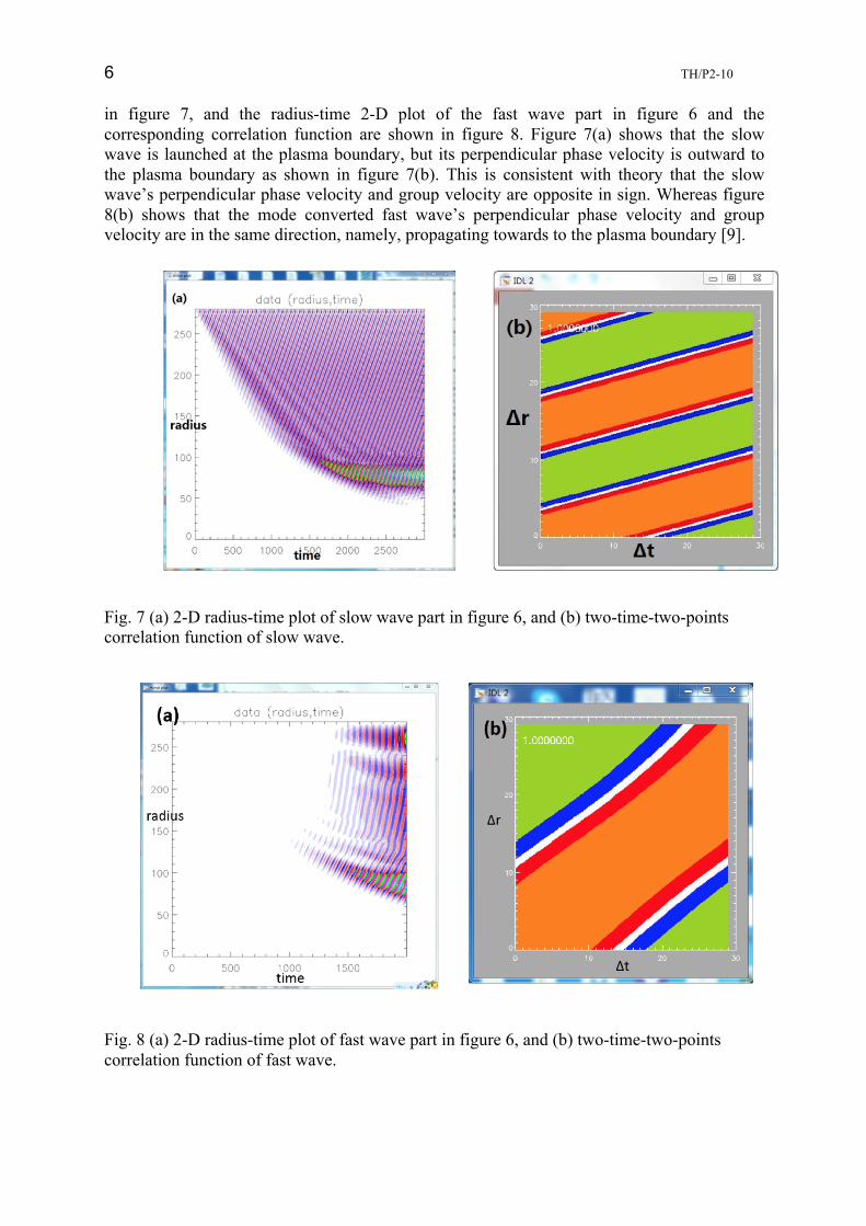
in figure 7, and the radius-time 2-D plot of the fast wave part in figure 6 and the corresponding correlation function are shown in figure 8. Figure 7(a) shows that the slow wave is launched at the plasma boundary, but its perpendicular phase velocity is outward to the plasma boundary as shown in figure 7(b). This is consistent with theory that the slow wave’s perpendicular phase velocity and group velocity are opposite in sign. Whereas figure 8(b) shows that the mode converted fast wave’s perpendicular phase velocity and group velocity are in the same direction, namely, propagating towards to the plasma boundary [9].
Fig. 7 (a) 2-D radius-time plot of slow wave part in figure 6, and (b) two-time-two-points correlation function of slow wave.
Fig. 8 (a) 2-D radius-time plot of fast wave part in figure 6, and (b) two-time-two-points correlation function of fast wave.
7 TH/P2-10
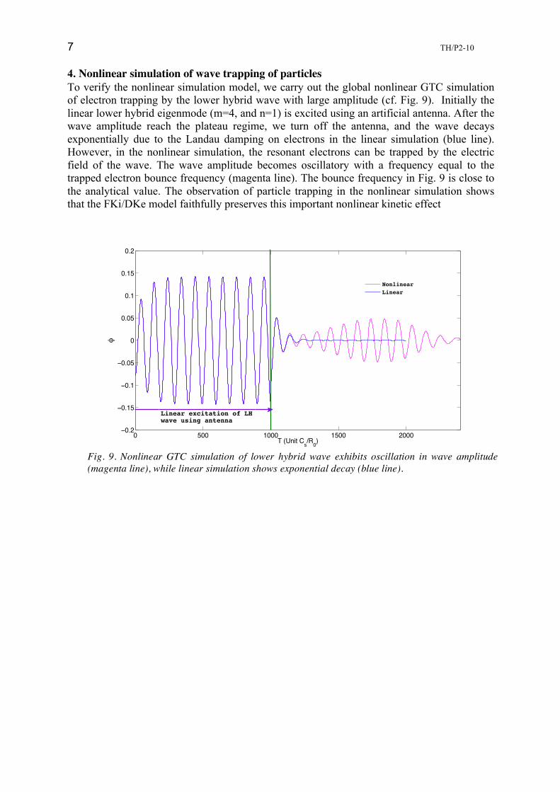
4. Nonlinear simulation of wave trapping of particles To verify the nonlinear simulation model, we carry out the global nonlinear GTC simulation of electron trapping by the lower hybrid wave with large amplitude (cf. Fig. 9). Initially the linear lower hybrid eigenmode (m=4, and n=1) is excited using an artificial antenna. After the wave amplitude reach the plateau regime, we turn off the antenna, and the wave decays exponentially due to the Landau damping on electrons in the linear simulation (blue line). However, in the nonlinear simulation, the resonant electrons can be trapped by the electric field of the wave. The wave amplitude becomes oscillatory with a frequency equal to the trapped electron bounce frequency (magenta line). The bounce frequency in Fig. 9 is close to the analytical value. The observation of particle trapping in the nonlinear simulation shows that the FKi/DKe model faithfully preserves this important nonlinear kinetic effect
0 500 1000 1500 2000−0.2
−0.15
−0.1
−0.05
0
0.05
0.1
0.15
0.2
T (Unit Cs/R0)
q
NonlinearLinear
Linear excitation of LHwave using antenna
Fig. 9. Nonlinear GTC simulation of lower hybrid wave exhibits oscillation in wave amplitude (magenta line), while linear simulation shows exponential decay (blue line).

8 TH/P2-10
Appendix 1: [1] C. Gormezano et al, Nucl. Fusion 47 S285-S336 (2007)
[2] ITER Physics Basis, Nucl. Fusion 39 2495-2539 (1999) [3] N. Fisch, Reviews of Modern Physics 59 175-234 (1987)
[4] Z. Lin, T.S. Hahm, W.W. Lee, W.M. Tang and R.B. White, Science 281, 1835 (1998). [5] A. Kuley, C. S. Liu, V. K. Tripathi, Phys. Plasmas 18, 032503 (2011). [6] A. Kuley , Z. X. Wang, Z. Lin and F. Wessel, Phys. Plasmas 20 102515 (2013).
[7] J. Bao, Z. Lin, A. Kuley, and Z.X. Lu, Plasma Phys. Contr. Fusion 95020 (2014). [8] Z. X. Lu, F. Zonca and A. Cardinali, Phys. Plasma 20 032115 (2013). [9] J. Bao and Z. Lin, in preparation (2014).