models for design of free-product recovery systems for petroleum hydrocarbon liquids
TRANSCRIPT

Models for Design of Free-Product Recovery Systems for Petroleum Hydrocarbon Liquids
Regulatory Analysis and Scientific Affairs Department
PUBLICATION NUMBER 4729AUGUST 2003

Models for Design of Free-ProductRecovery Systems for PetroleumHydrocarbon Liquids
Regulatory Analysis and Scientific Affairs Department
API PUBLICATION 4729
PREPARED UNDER CONTRACT BY:
Randall J. CharbeneauEnvironmental and Water Resources Engineering ProgramCollege of EngineeringThe University of Texas at Austin
August 2003

iii
FORWARD
API publications may be used by anyone desiring to do so. Every effort has been
made by the Institute to assure the accuracy and reliability of the data contained in
them; however, the Institute makes no representation, warranty, or guarantee in
connection with this publication and hereby expressly disclaims any liability of
responsibility for loss or damage resulting from its use or for the violation of any
federal, state, or municipal regulation with which this publication might conflict.

iv
ACKNOWLEDGMENTS
The author would like to acknowledge the following individuals for their
contributions of time and expertise during this study and in the preparation of this
report:
API STAFF CONTACT
Harley Hopkins, Regulatory Analysis and Scientific Affairs Department (RASA)
MEMBERS OF THE API SOIL AND GROUNDWATER TECHNICAL TASK
FORCE
Curtis Stanley, Shell Global Solutions; Chairman
Appreciation is extended to Victor Kremesec, BP plc; Ravi Kolhatkar, BP plc; and
Tom Henson, ExxonMobil, for their discussions, review and comments on this
work. A special acknowledgment is extended to Mark Adamski, BP plc, for many
discussions, ideas and data that have been incorporated in this manuscript,
including the example application presented in Section 4.4. Andrew Kirkman
(RETEC) is acknowledged for contributing to the review of the spreadsheet
models.

v
PREFACE This manuscript is presented as a supplement to API Publication Number 4682,
Free-Product Recovery of Petroleum Hydrocarbon Liquids, which was published in
June 1999. Model scenarios are described for free-product hydrocarbon liquid
recovery using single- and dual-pump well systems, skimmer wells, vacuum-
enhanced well systems, and trenches. Use of spreadsheet software to compute
recovery rates, volumes and times is discussed, and example applications are
provided. The basic modeling equations and background material are also
provided.

vi

vii
TABLE OF CONTENTS Section Page
Table of Contents................................................................................................ vii
List of Figures ....................................................................................................... x
Executive Summary ............................................................................................xiii
Section 1 INTRODUCTION 1.1 Background and Objectives .......................................................1
1.2 Scenarios for Free-Product Hydrocarbon Liquid Recovery ........2
1.2.1 Scenarios for Recovery Well Systems..................................3
1.2.2 Scenario for LNAPL Recovery Using Trenches ....................4
1.3 Overview ....................................................................................5
Section 2 LNAPL SATURATION AND RELATIVE PERMEABILITY DISTRIBUTIONS
2.1 LNAPL Saturation Distribution....................................................7
2.1.1 Capillary Pressure Scaling Relationships .............................7
2.1.2 Vertical Equilibrium ...............................................................9
2.1.3 LNAPL and Water Saturation Distribution...........................11
2.1.4 LNAPL-Layer Specific Volume, Do......................................16
2.2 LNAPL-Layer Relative Permeability .........................................17
Section 3 MODELS FOR LIQUID FREE-PRODUCT RECOVERY 3.1 Free-Product Recovery Using Well Systems ...........................21
3.1.1 Rate Equations for LNAPL Recovery..................................21
3.1.2 LNAPL-Layer “Specific Retention” ......................................22
3.1.3 “Enhanced” LNAPL Recovery Performance Equations ......23
3.1.4 Performance Equations for Skimmer Wells ........................24
3.1.5 Recovery Volume ...............................................................25
3.2 LNAPL Recovery Using Trenches............................................25

viii
Section 4 MODEL IMPLEMENTATION AND APPLICATIONS 4.1 Spreadsheet Models ................................................................27
4.2 Example Model Application ......................................................28
4.2.1 Data Entry Worksheet.........................................................28
4.2.2 Layer Calcs Worksheet.......................................................29
4.2.3 Distribution Charts Worksheet ............................................33
4.2.4 Well Worksheet ..................................................................34
4.2.5 Trench Worksheet ..............................................................37
4.3 LNAPL and Water Table Fluctuations ......................................38
4.4 Application of the Model to Fine-Grain Soil ..............................41
4.4.1 LNAPL Distribution in Fine-Grain Soil ................................42
4.4.2 Characterization of a Fine-Grain Soil Site ..........................43
4.4.3 Discussion ..........................................................................48
4.5 Model Implementation..............................................................49
Section 5 REFERENCES ……………………………………………………….. 51
APPENDIX A – HETEROGENEOUS SYSTEM
A.1 Introduction .............................................................................53
A.2 Capillary Pressure Relationships .............................................54
A.2.1 Saturation and Specific Volume for Heterogeneous
Media ..................................................................................54
A.2.2 LNAPL-Layer Relative Permeability....................................56
A.2.3 Spreadsheet Models for Heterogeneous Soil .....................57
A.2.4 Model Implementation: Specific Retention and
Hydraulic Conductivity ........................................................58

ix
APPENDIX B – VISUAL BASIC FUNCTION CALLS ..........................................61
APPENDIX C – REPRESENTATIVE VAN GENUCHTEN MODEL
PARAMETERS..........................................................................65
APPENDIX D – REPRESENTATIVE FLUID PROPERTIES...............................67
APPENDIX E – REPRESENTATIVE POROSITY AND
RESIDUAL SATURATION VALUES .........................................69

x
LIST OF FIGURES
Figure Page
1.1 Monitoring well LNAPL thickness, bo .........................................................3
1.2 Recovery well system with 11 recovery wells showing the
radius of capture ........................................................................................4
1.3 Simple Trench System for LNAPL Recovery..............................................5
2.1 Representative soil characteristic curve based on the van Genuchten
model with Swr = 0.15, α = 2.0 ft-1, and N = 4.0 ..........................................8
2.2 LNAPL saturation distribution...................................................................13
2.3 Influence of interfacial tension on LNAPL distribution based on the soil
characteristic curve of Figure 2.1 .............................................................15
2.4 LNAPL distribution as a function of monitoring well LNAPL
thickness, bo. Distributions correspond to values bo = 3, 2, 1,
and 0.5 feet. .............................................................................................16
2.5 Formation specific volume function, Do(bo)...............................................17
2.6 LNAPL saturation distribution in soil with properties from Figure 2.2
for bo = 2 feet............................................................................................19
2.7 LNAPL relative permeability distribution predicted by the Burdine
and Mualem models .................................................................................19
2.8 LNAPL-layer relative permeability functions ( )oro bk for the models
of Mualem (upper curve) and Burdine (lower curve) ................................20
4.1 Data Entry worksheet …………………………………………………………28
4.2 Parameter fitting worksheet Layer Calcs before selection of
curve-fitting values (bo,Do,kro)1 and (bo,Do,kro)2 ..............................................................30
4.3 Working table for fitting linear-segment models .......................................31
4.4 Fitted version of linear segment models for Do-bo and kro-bo ...................32
4.5 Saturation and relative permeability distribution.......................................33
4.6 Free-product recovery worksheet showing water-enhanced
recovery performance .............................................................................35

xi
4.7 Free-product recovery worksheet showing skimmer well
recovery performance ..............................................................................37
4.8 Free-product recovery system performance for a trench system .............38
4.9 LNAPL saturation distribution before and after a 1.44-feet decrease
in the water table elevation.......................................................................40
4.10 Schematic view of LNAPL distribution in macropores ..............................43
4.11 Fine-grain soil characteristic curve showing measured data with
fitted van Genuchten model .....................................................................44
4.12 LNAPL distribution in fine-grain soil with macropores ..............................45
4.13 Comparison of measured and predicted LNAPL recovery .......................47
4.14 Calibrated model with Rc = 12.5 ft and Kw = 1.9 ft/d .................................47
4.15 LNAPL saturation, relative permeability, and recovery curves
for a model simulation with positive LNAPL residual
saturation values ......................................................................................49
A.1 Simple heterogeneity (abrupt facies interface) in subsurface
porous media ...........................................................................................53
A.2 LNAPL and water distributions for heterogeneous soil with
properties corresponding to coarse texture layer overlying
fine texture layer.......................................................................................55
A.3 LNAPL-layer relative permeability function for homogeneous
coarse-texture soil, heterogeneous soil with fine-texture soil
overlying coarse-texture soil, and homogeneous soil with
fine-texture ...............................................................................................56
A.4 Data Entry worksheet showing data leading to Figure A.2 .......................58

xii

xiii
EXECUTIVE SUMMARY
This document addresses the application of proven technologies for recovering free-product petroleum releases to groundwater. The manuscript is a supplement to API Publication Number 4682, and documents spreadsheet models for design and analysis of liquid free-product recovery systems using single- and dual-pump wells, vacuum-enhanced wells, skimmer wells, and trenches. The principles that govern the distribution and movement of free-product petroleum hydrocarbons near the water table in an unconfined groundwater aquifer are reviewed. Models for predicting free-product recovery system performance are presented. Four spreadsheet models [LNAPL(vG-B).xls, LNAPL(vG-M).xls, LNAPL(vG-B-2L).xls, and LNAPL(vG-M-2L).xls] are described, and example applications are presented and discussed.
This manual is useful for evaluating remediation options at sites where free product is present at the water table of an unconfined aquifer or perched on a confining bed. It assumes that the reader has a basic understanding of hydrogeology and is aware of subsurface complexities (e.g., heterogeneity and water-table fluctuation) that complicate estimates of free-product recovery. Background material is presented in API Publication No. 4682, including a description of remediation technologies associated with free-product recovery, physical/chemical parameters that are essential in the design and analysis of free-product recovery systems, and information and data for parameter estimation. The most significant changes from API Publication No. 4682 that are included in the present model formulation are a focus on the van Genuchten representation for soil retention of fluid, and use of piece-wise linear equations to relate both the LNAPL specific volume and relative permeability functions to the monitoring-well thickness of the LNAPL layer. The explicit representation of the LNAPL-layer relative permeability function results in model predictions that differ most significantly from the previous model when the Mualem relative permeability model is selected. The capability for addressing the transient performance of skimmer wells and trench systems has been added. In addition, a simple case of aquifer heterogeneity with layers of different soil texture properties can be analyzed.

xiv

1
SECTION 1 – INTRODUCTION
1.1 Background and Objectives
The American Petroleum Institute (API) Publication Number 4682, Free-Product
Recovery of Petroleum Hydrocarbon Liquids (Charbeneau et al., 1999), provides an
overview of recovery technologies for petroleum hydrocarbon liquids that are released
to the subsurface environment and accumulate near the water table. The primary
recovery technologies include skimmer wells that produce hydrocarbon liquids and
single- and dual-pump wells that produce both water and hydrocarbon liquids.
Hydrocarbon liquid recovery rates may also be enhanced by applying a vacuum
pressure to the well to increase the gradient towards the well within the hydrocarbon
layer. API 4682 describes two (Excel spreadsheet) models that may be used to
characterize the subsurface distribution and mobility of liquid hydrocarbon (lighter-than-
water nonaqueous phase liquids, LNAPL), and to calculate the potential recovery rate
and time using single- and dual-pump wells, and vacuum-enhanced wells.
The present manuscript is a supplement to API 4682 that describes additional
work that was funded through API and supported by its Soil and Groundwater Technical
Task Force. The manuscript describes a more general modeling framework for
characterization of subsurface LNAPL distribution using the capillary pressure head-
saturation model of van Genuchten (1980), and for describing the mobility and potential
recovery using single- and dual-pump wells, vacuum-enhanced wells, skimmer wells
and trenches. Both the LNAPL layer volume and relative permeability are described by
fitting a piecewise linear model to the magnitudes calculated from vertical distributions
of hydrocarbon saturation and relative permeability based on the assumption of vertical
equilibrium (the valid range for this assumption is discussed in API 4682). The models
presented in Appendix A also simulate a simple case of soil heterogeneity with an
abrupt vertical change in soil texture, where the upper and lower layers may have
differing soil characteristics.

2
1.2 Senarios for Free-Product Hydrocarbon Liquid Recovery
Proven technologies for free-product recovery of petroleum hydrocarbon liquids
are described in API 4682. Models to provide quantitative estimates of system
performance must necessarily be based on simplifying assumptions that will not be
applicable to all field conditions. Nevertheless, the models provide insight and guidance
that should be helpful in technology selection and system design, and in analysis of
system performance. The model scenarios for well systems and trenches are
discussed separately.
The subsurface porous media is assumed to be homogeneous, as shown in
Figure 1.1. [A simple case of aquifer heterogeneity where a soil layer of one texture
overlies a layer with a differing texture, with an abrupt horizontal interface separating the
layers, is presented in Appendix A.] Figure 1.1 shows a monitoring well with an LNAPL
layer located between the air-NAPL interface zao and the NAPL-water interface zow. The
total monitoring well LNAPL thickness is bo. The elevation of the water table, zaw,
provides the datum for fluid levels. While the water table is not present because of the
LNAPL layer, its elevation is easily determined from the elevations zao and zow, and the
LNAPL density �o.

3
Water Tablezao
zow
zaw
LNAPLLayer
bo
Figure 1.1. Monitoring well LNAPL thickness, bo
The texture characteristics that must be defined for the porous media include the
porosity n; the van Genuchten parameters N and α; and the irreducible water saturation,
Swr; and residual LNAPL saturation values for the vadose zone and saturated zone, Sorv
and Sors. Fluid properties include the LNAPL density, ρo (it is assumed that the water
density is 1 g/cm3), and the water and LNAPL surface and interfacial tensions, σaw, σao,
and σow.
1.2.1. Scenarios for Recovery Well Systems
The basic scenario for free-product recovery using well systems is the same for
single- and dual-pump wells, vacuum-enhanced wells, and skimmer wells. The
performance of each well is characterized in terms of its radius of capture Rc, with a
typical scenario shown in Figure 1.2. This figure depicts a plan view of an LNAPL lens
(in gray color) with 11 recovery wells located so that the pattern of wells with their radius
of capture will cover the area of the lens. For single- and dual-pump well systems, the
radius of capture could extend out to the radius of influence (water production) of the
well. For vacuum-enhanced systems, the radius of influence of the vacuum extraction
well (which is typically on the order of 30 – 40 feet) limits the radius of capture. For

4
skimmer wells, the radius of capture is limited to a greater but unknown extent, which is
probably on the order of 10 – 20 feet.
Rc
Figure 1.2. Recovery well system with 11 recovery wells showing the radius of capture
The data required for analysis of recovery-well-system performance includes the
radius of capture for the well, the LNAPL viscosity (the water viscosity is assumed to be
1 cp), and water production rate for a water-enhanced system or wellhead vacuum
pressure for a vapor-enhanced system. For a water-enhanced system, the effective
depth of penetration of the well into the aquifer must be specified, while for a vacuum-
enhanced system, the screened interval of the vadose zone must be given along with
the effective relative permeability of the vadose zone (due to the presence of soil water,
the permeability of the vadose zone may be reduced from its air-saturated value). If
zero water production and wellhead pressure are specified, then the well is assumed to
function as a skimmer well.
1.2.2. Scenario for LNAPL Recovery Using Trenches
The modeling framework may also be used to represent a simple trench recovery
system, such as shown in Figure 1.3. The trench has a width WT transverse to the
direction of groundwater flow. The LNAPL lens is of length LT in the direction of
groundwater flow, and width WT. The natural groundwater hydraulic gradient Jw is
transferred to the floating LNAPL layer, and carries it into the trench where LNAPL is

5
removed by skimmer wells or other technology. The rate of LNAPL discharge into the
trench will depend on the effective lens thickness as observed in a monitoring well, soil
texture characteristics, the natural groundwater hydraulic gradient, and whether
groundwater is also produced from the trench in order to increase the hydraulic
gradient. If the trench cuts across an LNAPL lens, then the upstream and downstream
sections of the lens must be analyzed separately, with Jw being negative on the
downstream side.
WT
LT
Jw
bo(t)Qo(t)
LNAPL Lens
Trench
Qw
Figure 1.3. Simple Trench System for LNAPL Recovery
1.3. Overview
The models for well and trench recovery systems provide estimates of the
recovery volume and rate as a function of time. The mathematical models on which
these estimates are based use a simple representation of the LNAPL layer effective
saturation and permeability. However, the representation is consistent with the actual
formation distributions of LNAPL saturation and relative permeability under conditions of
vertical equilibrium, so that “continuity” is maintained within the modeling framework.
These representations are described in Section 2, which describes the saturation
distribution based on the van Genuchten (1980) capillary pressure model and conditions

6
of vertical equilibrium. This model was not described in API 4682, which focused on
application of the Brooks and Corey (1964) power law model for representing the soil
characteristics. The LNAPL layer relative permeability distribution is also described,
using both the Burdine (1953) and Mualem (1976) models to relate saturation and
relative permeability.
The mathematical models for predicting free-product recovery are developed in
Section 3. These models are based on the free-product thickness that one would
observe in a monitoring well that was in good communication with the formation fluids
(water, LNAPL, air). The rate equations for single- and dual-pump wells, vacuum-
enhanced wells, skimmer wells, and trench recovery systems depend on the monitoring
well LNAPL thickness and on the discharge of formation fluids (water or air). The
principle of continuity is applied to predict how the monitoring well LNAPL thickness
(and recovery rate) varies as a function of time. Section 4 presents a series of
examples that describe features of the model implementation and model application.
Appendix A describes an extended version of the model that addresses a simple
case of aquifer heterogeneity, with two layers having different soil texture
characteristics. Calculation of effective layer specific volume and relative permeability
are described for this two-layer case, and extension of the time-variable recovery
models are presented. Example applications are also provided.
Appendix B provides a listing of the Visual Basic function calls that are used in
the spreadsheets. Appendix C provides representative van Genuchten model soil
retention parameter values for different soil texture classes. Tables of representitive
fluid properties can be found in Appendix D. Appendix E contains porosity and residual
saturation values from the literature.

7
SECTION 2 – LNAPL SATURATION AND RELATIVE PERMEABILITY DISTRIBUTIONS
This section describes the vertical distribution of fluid saturation and relative
permeability for a homogeneous porous media. The resulting relationships are used to
develop simple representations of effective specific volume and relative permeability for
an LNAPL lens.
2.1 NAPL Saturation Distribution This subsection first considers the capillary pressure scaling relationships for
different fluid systems, and then the consequences of vertical equilibrium for describing
capillary pressure distributions are discussed. Results are used to estimate the
saturation distribution for homogenous porous media.
2.1.1 Capillary Pressure Scaling Relationships According to the van Genuchten (1980) model, the water saturation Sw is related
to the suction pressure head h through
( ) ( )( )
M
Nw hSShS
+−+=
α111 wrwr (2.1)
In equation 2.1, Swr is the irreducible (residual) water saturation and α, N and M are
model parameters (where M = 1 – 1/N; N = 1/(1-M)). The parameter α is for the air-
water fluid system, and its magnitude is inversely related to the thickness of the capillary
fringe. The Brooks and Corey (1964) displacement pressure head (Ψb) is related to α
through the approximate relation α ~ 1/Ψb. The parameter N is proportional to the pore-
size distribution index (λ) of Brooks and Corey, where roughly one has N = λ + 1.
Representative values for a sand soil are Swr = 0.15, α = 2.0 ft-1 and N = 4.0. The
resulting soil characteristic curve is shown in Figure 2.1.

8
0
0.5
1
1.5
2
2.5
0 0.2 0.4 0.6 0.8 1Water Saturation
Cap
illar
y P
ress
ure
Hea
d (ft
)
Figure 2.1. Representative soil characteristic curve based on the van Genuchten model with Swr = 0.15, α = 2.0 ft-1, and N = 4.0
Equation 2.1 may be used for other fluid combinations if appropriate scaling
relationships are introduced. It is assumed that water is the wetting fluid, air the
nonwetting fluid, and that LNAPL has intermediate wettability. For the three-phase
(water, LNAPL, air) system, Leverett’s (1941) assumption is that the water saturation is
a function of the LNAPL-water capillary pressure, while the total liquid saturation (water
plus LNAPL) is a function of the air-LNAPL capillary pressure.
The introduction of scaling relationships are based on Laplace’s equation (for
capillary pressures) that relates the pressure difference across an interface between
two fluid phases to the radius of curvature of this interface. For fluid phases i and j, this
equation may be written
cr
p 2σ ijcij = (2.2)
In equation 2.2, pcij is the capillary pressure (pressure in the nonwetting phase i minus
the pressure in the wetting phase j), σij is the surface or interfacial tension between
phases i and j, and rc is the radius of curvature of the interface that separates these
phases. The reasoning behind the scaling relationships is as follows. The right side of
equation 2.2 should be determined by the distribution of pores within the porous
medium and should be directly related to the fluid saturation (with the wetting phase

9
occupying the smaller pore sequences). A decrease in the radius of curvature would
correspond to the interface moving into pores of smaller size with larger capillary
pressure. This would correspond to a decrease in wetting phase saturation. [This does
not reflect hysteresis, wherein the sequence of filled pores is different upon drainage
and imbibition.] The left side of equation 2.2 can be scaled for different fluid
combinations.
For fluid combination i-j, the capillary pressure head parameter α may be scaled
following Leverett (1941):
ασσ
ρρρρ
αij
awij
−
−=
aw
ij (2.3)
In equation 2.3 the term containing the fluid density values appears because capillary
pressure head values are being scaled rather than capillary pressures. At standard
atmospheric pressure and a temperature of 20o C, the air density is 0.0012 g/cm3 and is
usually neglected compared with the water density of 1 g/cm3. Thus, for scaling the
capillary pressure head between LNAPL and water, equation 2.3 becomes
( ) ασσ
ρ1ασσ
ρρρ
αow
aw
ow
awow
−=
−= r
w
ow (2.4)
In equation 2.4, ρr is the LNAPL/water density ratio, or the LNAPL specific gravity.
Similarly, in scaling the capillary pressure heads between air and LNAPL, equation 2.3
takes the form
ασσ
ραao
awao
= r (2.5)
Equations 2.4 and 2.5 provide the appropriate scaling relationships.
2.1.2 Vertical Equilibrium Use of equation 2.1 and appropriately scaled capillary pressure relations to
describe the vertical distribution of fluid saturation requires the assumption of vertical
equilibrium, wherein the pressure in each phase satisfies the hydrostatic pressure
equation. To help develop ideas, consider the LNAPL-water system. The hydrostatic

10
pressure equation for the LNAPL and water phase take the following form for an
incompressible fluid.
( ) ( ) ( )*ρ* zzgzpzp ooo −−=
(2.6)
( ) ( ) ( )*ρ* zzgzpzp www −−=
In equation 2.6, z* is a reference elevation that will be selected based on the following
discussion. The capillary pressure is the pressure difference between the nonwetting
and wetting phases (for this case this is designated as pcow), and thus the capillary
pressure distribution between LNAPL and water under conditions of vertical equilibrium
is given by
( ) ( ) ( ) ( )*ρρ*cowcow zzgzpzp ow −−+= (2.7)
It is most useful to select a reference elevation where the capillary pressure vanishes,
that is, the pressure in the nonwetting and wetting phases are the same. From equation
2.2, this would require that the radius of curvature of the interface between the phases
be large (infinite). This would be the case of a monitoring well in equilibrium with
formation fluids, and with reference to Figure 1.1, the elevation z* = zow serves as the
appropriate datum. Thus the capillary pressure head distribution under conditions of
vertical equilibrium may be specified by
( ) owcow
ow ρρzz
gp
how
−=−
= (2.8)
To show consistency of the scaling relationships for equation 2.1 note that
( ) hg
ph
oww
ow αρρ
ασσ
ρρρ
α cow
ow
awowow =
−×
−= (2.9)
The last step in equation 2.9 follows from equation 2.2, according to which, pcow/σow =
pcaw/σaw = pc/σ, and h = pc/(�w g).
In a similar fashion to equation 2.8, for the air-LNAPL system one finds
aoao zzh −= (2.10)

11
In equation 2.10, zao is the elevation of the air-LNAPL interface in a monitoring well, as
shown in Figure 1.1. Finally, using similar arguments for the water phase we have
awaw zzhh −=≡ (2.11)
Together, equations 2.8, 2.10 and 2.11 allow one to calculate the pressure distribution
within any phase under conditions of vertical equilibrium. For all developments below,
the water table is the elevation datum, and zaw = 0. Other elevations are referenced to
this datum.
2.1.3 LNAPL and Water Saturation Distribution Equation 2.1 may be written as
( ) ( )( )
M
Nw
w hSShS
h
+=
−
−=
α11
1Θ
wr
wr (2.12)
In equation 2.12, Θw is the air-water reduced saturation, and it scales the water
saturation to range between values of 0 and 1. In order to apply this equation to other
fluid-phase pairs, the appropriate reduced saturation functions must be identified, which
also must have values that scale to range from 0 to 1. Using the Leverett assumptions
for the LNAPL-water pair, along with equations 2.8 and 2.4 for vertical equilibrium and
capillary scaling, the water saturation distribution may be represented by the following
equation:
( ) ( )( )( )
M
Nw zzSSSzS
−+−−+=
owoworswrwr α1
11 (2.13)
In equation 2.13, Sors is the residual LNAPL saturation in the saturated zone and zow is
the elevation of the LNAPL-water interface in a monitoring well. In a similar fashion, for
the total liquid (water plus LNAPL)-air saturation distribution, equation 2.12 becomes
( ) ( )( )( )
M
Nt zzSSSSzS
−+−−++=
aoaoorvwrorvwr α1
11 (2.14)

12
In equation 2.14, St(z) = Sw(z) + So(z), Sorv is the residual LNAPL saturation in the
vadose zone, and zao is the elevation of the air-LNAPL interface in a monitoring well.
For elevation z < zao, all of the pore space is filled with liquid (water plus LNAPL), so St
= 1. Likewise, for elevation z < zow, all of the pore space is filled with water plus residual
LNAPL (if any is present), so Sw = 1 – Sors.
Given equations 2.13 and 2.14, the LNAPL distribution may be found from
( ) ( ) ( )zSzSzS wto −= (2.15)
Equation 2.15 predicts the total saturation of LNAPL, and does not reflect the fact that a
fraction of this LNAPL phase will remain trapped within the saturated and vadose zones
(given by the values of Sors and Sorv, respectively).
Figure 2.2 shows the LNAPL saturation distribution corresponding to a
monitoring-well LNAPL thickness bo = 2.0 feet, for a soil with same texture properties
used in Figure 2.1. The horizontal dashed line marks the elevation of the water table.
The box on the right side shows the monitoring-well LNAPL thickness. The LNAPL
curve shows the free-product LNAPL saturation distribution, as predicted using
equations 2.13 to 2.15. The dashed curve on the left side of the figure marks the
residual LNAPL distribution. For this case, residual LNAPL extends above and below
the free-product LNAPL layer. The extension of the residual LNAPL distribution within
the free-product layer shows the saturation distribution that would become immobile as
LNAPL is recovered. However, all LNAPL within the free-product layer is considered
mobile. Capillary forces trap LNAPL only as the LNAPL saturation is reduced.

13
-2.50
-2.00
-1.50
-1.00
-0.50
0.00
0.50
1.00
1.50
2.00
2.500.0 0.2 0.4 0.6 0.8 1.0
LNAPL Saturation
Ele
vatio
n [ft
]
Residual LNAPL
Water Table
LNAPL
Monitoring Well LNAPL Thickness
Figure 2.2. LNAPL saturation distribution
The maximum elevation of free-LNAPL (LNAPL saturation greater than residual)
is found by setting So(z) = Sorv in equation 2.15 and solving for z = zmax. This leads to
the equation
( )[ ] ( )[ ]NN zzAzzA owowaoao αα1 −−−=− (2.16)
In equation 2.16,
M
SSSS
A1
orswr
orvwr
11
−−−−
= (2.17)
In general, equation 2.16 must be solved iteratively for z = zmax. However, in the special
case where Sorv = Sors one finds A = 1 and
owao
owowaoao*max αα
αα−−
==zz
zz (2.18)
However, zao and zow are related to the LNAPL layer thickness in a monitoring well, bo,
through
or bzz ρowaw =− (2.19)
( ) or bzz ρ1awao −=− (2.20)

14
In equations 2.19 and 2.20, �r is the LNAPL specific gravity. Selecting zaw as the datum
(zaw = 0), equation 2.18 may be reduced to the form
( )( )( ) or
rr
r bz ρσρ1σρρ1σσ
aoow
owao*max
−−
−+= (2.21)
Equation 2.21 leads to the following model-specific requirement between the surface
and interfacial tensions, and the specific gravity:
aoow σρρ1σr
r−> (2.22)
The LNAPL capillary-rise increases indefinitely as the limit in equation 2.22 is
approached. Examination of the resulting LNAPL distributions as this limit is
approached shows that the limiting condition corresponds to infinite capillary rise of an
LNAPL film (infinitely small saturation above residual), presumably associated with a
positive spreading coefficient against the pull of gravity. These small saturation values
do not significantly impact the effective LNAPL-layer specific volume and relative
permeability, and thus they may be ignored in issues of free-product recovery.
However, if the conditions specified by equation 2.22 do not hold, then an algorithm
based on solution of equation 2.16 for the maximum elevation of free-LNAPL cannot be
used.
Field data show measured surface and interfacial tension values that do not
satisfy equation 2.22. An alternative algorithm for estimating the effective capillary rise
is to work directly with equation 2.15 and search with increasing elevation for the
condition where
( ) εorv ≤− SzSo (2.23)
In equation 2.23, � is a sufficiently small value (say 0.001) and the elevation that first
satisfies this equation is taken as zmax.
Equations 2.13, 2.14 and 2.15 may be used to find the LNAPL saturation
distribution within the groundwater formation corresponding to a given monitoring well
LNAPL thickness under conditions of vertical equilibrium. Figure 2.3 shows the LNAPL
saturation distribution for the soil characteristic curve of Figure 2.1 corresponding to a
monitoring well LNAPL thickness value of bo = 2.0 feet with �r = 0.75, Sorv = 0.05, Sors =

15
0.15, and σao = 25 dyne/cm. The horizontal dashed line shows the elevation of the
water table, and the largest LNAPL saturation values occur within the upper part of the
water table capillary fringe. The two curves that are shown differ in values of σow, with
the curve with greater capillary rise having σow = 5 dyne/cm compared with 25 dyne/cm
for the other curve. From this figure it is seen that the most significant effect of
increasing σow values is to decrease the LNAPL saturation below the water table and
within the capillary fringe. There is also a increase in the LNAPL capillary rise, though it
does not result in a large increase in LNAPL saturation above residual at locations
above the water table.
-3
-2
-1
0
1
2
3
40 0.2 0.4 0.6 0.8 1
LNAPL Saturation
Elev
atio
n [ft
]
Figure 2.3. Influence of interfacial tension on LNAPL distribution based on the soil characteristic curve of Figure 2.1. The thin curve with greater capillary rise has σow = 5 dyne/cm, while the thick curve corresponds to σow = 25 dyne/cm and is the same distribution as shown in Figure 2.2.
Figure 2.4 shows the LNAPL saturation distribution for monitoring well LNAPL
thickness values of bo = 3, 2, 1, and 0.5 feet, for the condition with σow = 25 dyne/cm
and other parameters as shown in Figures 2.1 to 2.3. The significant decrease in “free-
product” with decreasing bo is apparent.

16
-3
-2
-1
0
1
2
30 0.2 0.4 0.6 0.8 1
LNAPL Saturation
Elev
atio
n [ft
]
Figure 2.4. LNAPL distribution as a function of monitoring well LNAPL thickness, bo. Distributions correspond to values bo = 3, 2, 1, and 0.5 feet. The dashed vertical lines above and below the water table correspond to residual LNAPL values Sorv = 0.05 and Sors = 0.15. It is saturation values in excess of these that are considered recoverable.
2.1.4 LNAPL-Layer Specific Volume, Do
A measure of great interest in efforts to quantify free product is the relationship
between the monitoring well LNAPL thickness, bo, and the specific free-product volume
(volume of LNAPL per unit surface area). The specific free-product volume, Do, may be
calculated from
( ) ( ) dzzSnbDz
zooo ∫=
max
ow
(2.24)
The function Do(bo) tends to be well-behaved and may be approximated piecewise by a
linear function of the form
( )χ−= oo bD β (2.25)
Figure 2.5 shows the “specific storage” function Do(bo) for the two parameter sets used
to develop Figure 2.3. For each parameter set, the solid curves show the calculated
function while the dashed line segments show the piecewise linear fit with three
segments. It is difficult to distinguish the solid and dashed curves, showing that a three-
segment linear model provides an adequate fit to equation 2.24 for the parameter sets,
and this is generally thought to be the case.

17
0
0.2
0.4
0.6
0.8
1
1.2
0 0.5 1 1.5 2 2.5 3 3.5
Monitoring Well LNAPL Thickness [ft]
Form
atio
n Sp
ecifi
c Vo
lum
e [ft
]
Figure 2.5. Formation specific volume function, Do(bo). The lower curve corresponds to the condition with σow = 25 dyne/cm in Figure 2.3, while the upper curve corresponds to σow = 5 dyne/cm. 2.2 LNAPL-Layer Relative Permeability
The vertical distribution of water and LNAPL saturation may be used to estimate
the vertical distribution of LNAPL relative permeability, which in turn may be used to
assess LNAPL mobility and potential recovery rates. Methods for relating LNAPL
saturation-capillary pressure to relative permeability are based on models of pore size
distribution and association of permeability to various pore sizes occupied by LNAPL.
One issue that arises concerns identification of the appropriate value for residual
LNAPL saturation; the same model is used both above and below the water table, and
selection of Sorv or Sors is uncertain. A decision was made to set the residual LNAPL
value to zero during application of the relative permeability models. This decision
results in the following model equations.
Using a three-phase integration of the Burdine (1953) equations with the Brooks
and Corey (1964) soil characteristic model (power-law model), the LNAPL relative
permeability may be calculated from
( )
−−
−
−−
=
++λ2λ
wr
wrλ2λ
wr
wr2ro 11
,SSS
SSS
SSSk wtoow (2.26)

18
In equation 2.26, St is the total liquid saturation (So + Sw), and λ is the pore size
distribution index. The pore size distribution index may be estimated from van
Genuchten model parameters using (Lenhard et al., 1989)
( )M
MM 15.011
λ −−
= (2.27)
Similarly, a three-phase integration of the Mualem (1976) equation with van
Genuchten’s soil characteristics function (Parker et al., 1987) gives
( )2
1
wr
wr
1
wr
wr21ro 1
11
1,
−−
−−
−−
−=
MM
t
MM
woow S
SSSSS
SSSk (2.28)
In equations 2.26 and 2.28, the leading term accounts for tortuosity while the second
term within brackets accounts for LNAPL-occupancy of pores within a given range.
Equations 2.26 and 2.28 predict different distributions of LNAPL relative
permeability for the same set of fluid saturation values, with equation 2.28 generally
predicting larger values for LNAPL relative permeability. For example, Figure 2.6
compares the LNAPL saturation distribution of Figure 2.2 (with σow = 25 dynes/cm) with
the case with Sorv = Sors = 0. In the former case the value of zmax is 1.53 feet, while in
the latter, zmax = 1.47 feet (for comparison, zmax* = 1.50 feet from equation 2.21). This
figure suggests that setting Sorv = Sors = 0 does not significantly effect the values of
LNAPL saturation throughout most of the lens thickness. The corresponding effect on
the effective lens relative permeability should also be minor because the relative
permeability associated with small LNAPL saturation values (where the difference
between the two curves is largest) is small.

19
-3
-2
-1
0
1
2
30 0.2 0.4 0.6 0.8 1
LNAPL Saturation
Elev
atio
n [ft
]
Figure 2.6. LNAPL saturation distribution in soil with properties from Figure 2.2 for bo = 2 feet. The two curves correspond to Sorv = 0.05, Sors = 0.15, and Sorv = Sors = 0.
Figure 2.7 shows the LNAPL relative permeability distribution predicted by
equations 2.26 and 2.28 for the LNAPL saturation distribution of Figure 2.6 (with zero
residual saturation values). The solid curve is the Burdine model while the dashed
curve corresponds to Mualem’s model. Mualem’s model predicts larger relative
permeability values.
-2.0
-1.0
0.0
1.0
2.00 0.2 0.4 0.6 0.8 1
LNAPL Relative Permeability
Elev
atio
n [ft
]
Figure 2.7. LNAPL relative permeability distribution predicted by the Burdine (equation 2.26; solid line) and Mualem (equation 2.28; dashed line) models, corresponding to the LNAPL saturation distribution shown in Figure 2.6 with zero residual saturation values.

20
For the LNAPL relative permeability distributions predicted by using equations
2.13, 2.14 and 2.15 [with Sorv = Sors = 0] with either equation 2.26 or 2.28, a variable of
interest is the effective relative permeability of the LNAPL layer. This may be calculated
from
( ) ( ) ( )( ) dzzSzSkb
bkxz
zow
oo ∫=
ma
ow
,1roro (2.29)
While equation 2.29 cannot be evaluated analytically, it is well behaved and can
be approximated using a piecewise linear function of the form
( )ξηro −= obk (2.30)
Figure 2.8 shows the LNAPL-layer relative permeability function ( )obk ro for the
two relative permeability models. As expected, the Mualem model has larger
permeability values for a given LNAPL-layer thickness. Also shown in the figure are the
piecewise linear approximations, with three segments in each case.
0
0.1
0.2
0.3
0.4
0.5
0.6
0.7
0.8
0.0 0.5 1.0 1.5 2.0 2.5 3.0 3.5Monitoring Well LNAPL Thickness [ft]
LNAP
L-La
yer R
elat
ive
Perm
eabi
lity
.
Figure 2.8. LNAPL-layer relative permeability functions ( )oro bk for the models of Mualem (upper curve) and Burdine (lower curve). The dashed curves show the piecewise linear fit model representation.

21
SECTION 3 – MODELS FOR LIQUID FREE-PRODUCT RECOVERY
In modeling LNAPL recovery using wells or trenches for conditions of vertical
equilibrium, both the specific volume and LNAPL-layer relative permeability may be
represented as piecewise linear functions of the monitoring well LNAPL thickness.
These representations are expressed in equations 2.25 and 2.30, and Figures 2.5 and
2.8 suggest that the layer functions may be adequately fit using a three-segment model.
These representations allow development of relatively simple models for predicting the
performance of free-product recovery systems. This section presents the basic
equations for well systems and for trenches.
3.1 Free-Product Recovery Using Well Systems For single- and dual-pump wells, and for vacuum-enhanced well systems,
production of water or air creates the hydraulic gradient that is responsible for LNAPL
migration to the recovery well. For skimmer wells, the LNAPL drawdown at the well
creates the gradient, and a different rate equation is followed. Rate equations are
combined with continuity and specific retention parameters for the LNAPL layer to
develop performance equations for the recovery system.
3.1.1 Rate Equations for LNAPL Recovery Under conditions where the LNAPL recovery rate is determined by water
production, the water and LNAPL discharge are related through (see Charbeneau et al.,
1999, Charbeneau et al., 2000)
wr
owr
wow
owwoo b
bQkbbQk
Qµ
ρµρ
ρ roro ≡=µ (3.1)
In equation 3.1 µr is the LNAPL/water viscosity ratio and bw is the effective thickness of
the aquifer, which in the case of a thick formation, is determined by the length of well
screen. Similarly, when LNAPL recovery is determined through airflow (vacuum-
enhanced recovery), the air and LNAPL discharge are related through
wo
oaar
wow
oaaoo Lk
bQkLkbQk
Qra
ro
ra
ro µρµρµρ
µ≡= (3.2)

22
In equation 3.2, µa is the dynamic viscosity of air (which is assumed to be 0.018 cp), Qa
is the air discharge, rak is the average relative permeability of the vadose zone, and Lw
is the length of well screen in the vadose zone for airflow.
The rate equation for a skimmer well was developed by Dr. Russell Johns (see
Johns et al., 2003). The LNAPL discharge is given by
( )( )
( )( )wr
owrr
wow
owwoowo rR
bkKrR
bkKQ
lnµρρ1π
lnµρµρρρπ 2
ro2
2ro −
≡−
= (3.3)
In equation (3.3), Kw is the hydraulic conductivity of the formation, R is the radius of
influence of the skimmer well, and rw is the skimmer well radius.
In LNAPL recovery, one may apply water and vacuum enhancement to increase
the recovery rate, so that equations 3.1 and 3.2 may be added. The skimmer well
equation 3.3 reflects LNAPL recovery without any enhancement of the rate, and thus it
stands alone.
3.1.2 LNAPL-Layer “Specific Retention” Within a radius of capture, Rc, the total LNAPL free-product volume is a function
of the monitoring well LNAPL thickness:
( ) ( ) ( )χ−== ocoocoo bRbDRbV βππ 22 (3.4)
Not all of this volume can be recovered through liquid free-product recovery
technologies because of residual saturations that exist within the vadose zone and
saturated zone as the LNAPL thickness is reduced. If the monitoring well LNAPL
thickness was reduced to zero, the remaining residual LNAPL volume within the zone of
recovery may be calculated as
( ) ( )[ ] ( )tbSnSnRtV orrc orsorv2
or ρρ1π +−= (3.5)
The difference between the volumes in equations 3.4 and 3.5 represents the
recoverable free-product volume, which may be written as
( ) ( ) ( ) [ ]oocooooo bDRbVbVbV γπ 2or −=−= (3.6)
In equation 3.6,
γ = (1-ρr) n Sorv + ρr n Sors (3.7)

23
Equation 3.6 for the recoverable free-product volume may be written
( ) ( ) ( )χβπγβπ 22cocoo RbRbV −−= (3.8)
where the last term in equation 3.8 is a constant. The most important use of equation
3.8 is to relate changes in recoverable free-product volume to changes in monitoring
well LNAPL thickness:
( ) ( ) ocoo dbRbdV γβπ 2 −= (3.9)
The parameter γ plays the same role in continuity for the LNAPL layer as the specific
retention plays in continuity at the water table of an unconfined aquifer, as the water
level rises and falls. In this regard, (β – γ) plays the role of the specific yield
(Charbeneau, 2000).
3.1.3 “Enhanced” LNAPL Recovery Performance Equations The performance equations for the various LNAPL recovery technologies are
based on the continuity equation for recoverable LNAPL within the region of capture,
which takes the form
oo QdtdV
=− (3.10)
With equation 3.9, equation 3.10 may be written
( )γβπ 2 −
−=c
oo
RQ
dtdb (3.11)
Equation 3.11 along with the relation Qo(bo) and initial condition bo(0) may be solved to
give the monitoring well LNAPL thickness bo(t). With equations 2.30, 3.1 and 3.2,
equation 3.11 gives the differential equation
( ) ooko bbAdtdb
ξ−−= (3.12)
In equation 3.12, the index k refers to either water or air enhancement [for both the
leading coefficient may be written (Aw + Aa)]. Equation 3.12 may be integrated to give
( )( ) ( )( )( ) ( ) tA
btbtbb
koo
oo ξ0ξ
ξ0ln =
−− (3.13)

24
Equation 3.13 may be arranged to give
( ) ( )( ) ( )[ ] tA
oo
oo kebb
btb ξξ00
0ξ−−−
= (3.14)
Equation 3.14 is appropriate when ξ is not equal to zero (ξ must approach 0 as bo
approaches zero). For ξ = 0 the integral becomes
( ) ( )( ) ( )tAbbtb
ko
oo 01
0+
= (3.15)
In equations 3.14 and 3.15,
( ) wowc
wwow bR
QA
µργβπηµρ
2 −= (3.16)
( ) wowc
aoa LkR
QA
ra2
a
µργβπηµρ
−= (3.17)
Equations 3.14 through 3.17 provide the performance equations for “enhanced” LNAPL
recovery using single and dual-pump wells and vacuum-enhanced recovery systems.
3.1.4 Performance Equations for Skimmer Wells When both Qw = 0 and Qa = 0, then the recovery well functions as a skimmer
well. Together, equations 3.3 and 3.10 then give
( ) 2ξ ooso bbAdtdb
−−= (3.18)
This equation may be integrated to give
( ) ( )( )( ) ( )( )( ) ( ) tA
tbbbtb
btb oo
oo
oos2 ξ0
0ξln
ξ1
0ξ1
ξ1
−=
−−
+− (3.19)
In equations 3.18 and 3.19,
( )( ) ( )
( )( ) ( )wrc
wrr
wowc
wwoow
rRRK
rRRK
Alnµγβ
ηρρ1lnµργβ
ηµρρρ222s
−
−=
−
−= (3.20)
When ξ = 0, equation 3.18 becomes

25
3os
o bAdtdb
−= (3.21)
The integral of equation 3.21 is
( )( ) tbA
btbo
oo 2s 02110)(
+= (3.22)
Equations 3.19 and 3.22 with 3.20 provide the performance equations for a skimmer
well.
3.1.5 Recovery Volume The performance equations provide the monitoring well LNAPL thickness as a
function of time. In the case of equation 3.19, this is an implicit function and must be
handled differently than the others. Once bo(t) is known, the volume recovered during a
time increment ∆t = t2 – t1 may be calculated from
( ) ( ) ( ) ( )( )212 γβπ tbtbRtV ooco −−=∆∆ (3.23)
Furthermore, the LNAPL discharge may be calculated using equations 3.1, 3.2 or 3.3.
3.2 LNAPL Recovery Using Trenches The same modeling framework may also be used to represent a simple trench
recovery system, such as shown in Figure 1.3. The rate of LNAPL recovery can be
enhanced through production of water from the trench. Otherwise, the natural
groundwater gradient Jw is responsible for the movement of LNAPL into the trench
where it is removed by skimmer wells or other technology.
The rate of LNAPL flow into the trench depends on both the hydraulic gradient
within the LNAPL layer and the effective layer relative permeability. The LNAPL
discharge may be calculated from
( ) ( ) ( ) ooooTo JKbktbWtQ ro= (3.24)
In equation 3.24, the trench discharge varies with time because the effective
LNAPL layer thickness decreased in with time, and because the LNAPL layer relative
permeability is a function of the lens thickness. The lens gradient is the same as the

26
natural groundwater hydraulic gradient (i.e., Jo = Jw) unless there is groundwater
production from the trench. In this latter case, it is assumed through superposition that
groundwater production creates an inward gradient on each side of the lens, and the
resulting LNAPL layer gradient may be calculated from
wTw
wwo bWK
QJJ2
+= (3.25)
In equation 3.25 bw is the effective groundwater capture depth of the trench.
The continuity equation for the LNAPL lens may be written following equation
3.11 in the form
( ) ( )ξγβ
η−
−
−= ooT
ooo bbL
JKdtdb (3.26)
Equation 3.26 has the same form as equation 3.12 with solution given by equations
3.14 and 3.15. These provide the performance equations for the trench recovery
system. The factor Ak is specified by the term within brackets in equation 3.26. More
explicitly, this factor may be written
( )
+
−=
wTw
ww
Tow
wwoT bWK
QJ
LK
A2γβµρ
ηµρ (3.27)
Note that for both the trench and the skimmer well, the aquifer hydraulic conductivity
appears explicitly in the performance equations.
If the trench bisects an LNAPL lens, then the recovery model may be applied
separately to each section of the lens. This is only feasible if water is also produced
from the trench to create an inward gradient on each side. For the section on the
downgradient side of the trench, the natural gradient Jw should be specified as a
negative number.

27
SECTION 4 – MODEL IMPLEMENTATION AND APPLICATIONS
The models described in Section 3 have been implemented through two separate
and standalone spreadsheets: LNAPL (vG-B).xls and LNAPL (vG-M).xls. As the
naming attempts to imply, these two models are for homogeneous soil with the van
Genuchten soil characteristic model, and with application of the Burdine and Mualem
models for calculation of the relative permeability. This section describes the
spreadsheet models, an example application, features of model implementation, and
case study applications.
4.1 Spreadsheet Models Each of the spreadsheet models has one worksheet for entry of basic data (Data
Entry). A second worksheet (Layer Calcs) is used in calculation of LNAPL-layer specific
volume and relative permeability parameters (χi, βi, ξi, ηi; i = 1,2,3) from equations 2.25
and 2.30, where the index is associated with each of the three linear segments. To
facilitate calculation of these parameters, a series of 26 data values (Do and kro as a
function of bo) are calculated using the model equations presented in Section 2.
Identification of the three linear segments requires specification of four sets of values
(bo, Do, kro)j, j = 0, 1, 2, 3. The sets corresponding to j-values 0 and 3 are specified by
the model: (0, 0, 0)0 and (bomax, Do(bomax), kro(bomax))3, where bomax is the maximum
LNAPL monitoring well thickness that is specified on the Data Entry worksheet. The
other two sets are selected from the series of 26 data values that have been calculated
(as shown below). The third worksheet (Distribution Charts) allows viewing of the
LNAPL, reduced-LNAPL (with residual saturation values set to zero), and water
saturation profiles, and the LNAPL relative permeability profile for selected values of the
monitoring well LNAPL thickness bo. The fourth worksheet (Well) is for calculation of
the LNAPL recovery. Required variables for water or air-enhanced systems, or for
skimmer wells are entered, and the time history of the LNAPL thickness, volume
recovery, and recovery rate are calculated and shown graphically. The fifth worksheet
(Trench) calculates LNAPL recovery using a trench. A description of model application
follows.

28
4.2 Example Model Application This subsection outlines the model application for the sand soil with characteristic
curve shown in Figure 2.1. Each of the model worksheets is described, and model
parameters and application are discussed.
4.2.1 Data Entry Worksheet This example shows the model application for the soil characteristic curve shown
in Figure 2.1, leading to Figure 2.2 for a LNAPL layer in a sand soil. Figure 4.1 shows
the basic Data Entry worksheet. The maximum LNAPL monitoring-well thickness is
specified. The LNAPL specific storage and relative permeability models are fit for
thickness values from zero to this maximum thickness. This is also the starting
thickness for estimation of recovery time and LNAPL recovery volumes and rates. The
soil characteristic variables include the irreducible water content and the residual
LNAPL saturation for the saturated and vadose zones. Fluid characteristics include the
LNAPL density and surface/interfacial tension values. Appropriate units are shown.
Calculated parameters include the maximum free-product elevation (using equation
2.23) and the Brooks and Corey soil characteristic parameters that correspond to the
selected van Genuchten variables.
Maximum Monitoring Well Calculated ParametersLNAPL Thickness [feet] M = 0.750 van Genuchten "M"
bo = 3.000 αao = 3.900 air/LNAPL "α" [ft-1]αow = 1.300 LNAPL/water "α" [ft-1]
Soil Characteristic zao = 0.750 elevation of air-LNAPL interface [ft]
n = 0.400 porosity zow = -2.250 elevation of LNAPL-water interface [ft]
N = 4.000 van Genuchten "N" zmax = 2.180 maximum free-product elevation [ft]
α = 2.000 van Genuchten "α" [ft-1] λ = 1.809 pore-size distribution index
Swr = 0.150 irreducible water saturation Ψb = 0.359 B-C displacement pressure head [ft]
Sorv = 0.050 residual LNAPL saturation (saturated)Sors = 0.150 residual LNAPL saturation (vadose) Press Ctrl-Shift+S to calculate sheet
Fluid Characteristics:ρo = 0.750 LNAPL density [gm/cc]
σaw = 65.000 air/water surface tension [dyne/cm]σao = 25.000 air/LNAPL surface tension [dyne/cm]σow = 25.000 LNAPL/water surface tension [dyne/cm]

29
Figure 4.1. Data Entry worksheet shows data leading to Figure 2.2. Only the data on the left side are entered. The parameters on the right are computed from entered data. 4.2.2 Layer Calcs Worksheet
Once the basic data are entered (and computed), the second worksheet
calculates values of Do and kro for twenty-six equally spaced bo-values within the range
from 0 to the maximum value specified at the top of Figure 4.1. These values are
plotted, as shown in Figure 4.2, with the triangles corresponding to the LNAPL specific
volume and the diamonds the relative permeability values. The integrals expressed by
equations 2.24 and 2.29 are evaluated using Simpson’s rule, and the parameters Eps-
Do and Eps-kro give the iteration convergence tolerance for each integral
approximation. The smaller the value, the more accurate the calculation of Do(bo) and
kro(bo), and the longer the computation time. Strategically, it is probably best to start
with a larger value (say 0.001), look at the resulting data curve that should be smooth
and well behaved, and then decrease the value as necessary.

30
Data for curve-fitting segments Press Ctrl-Shift+S to calculate sheetbo Do kro χ β ξ η
0.000 0.000 0.0000.240 0.025 0.000 0.0000 0.105203 0.0000 0.0000061.080 0.219 0.127 0.1305 0.230559 0.2400 0.150923 0.0001 Eps-Do3.000 0.876 0.455 0.4401 0.342086 0.3374 0.170711 0.00001 Eps-kro
0.00
0.10
0.20
0.30
0.40
0.50
0.60
0.70
0.80
0.90
1.00
0.00 0.50 1.00 1.50 2.00 2.50 3.00 3.50Monitoring well LNAPL thickness [ft]
Spec
ific
Volu
me
[ft] (
red)
/R
elat
ive
Perm
eabi
lity
(blu
e)
Figure 4.2. Parameter fitting worksheet Layer Calcs before selection of curve-fitting values (bo,Do,kro)1 and (bo,Do,kro)2.
On the Layer Calcs spreadsheet page, the table of 26 calculated values of bo, Do
and kro are listed below the figure that is shown in Figure 4.2, in rows 40-65 and
columns B-D of the spreadsheet. These values correspond to 26 equally-space values
of bo within the range 0-bomax. Thus for this example, the spacing is ∆bo = bomax/25 =
3.0/25 = 0.12 feet, and the (bo)j series has values (0, 0.12, 0.24, 0.36, …). The dashed
linear segments in Figure 4.2 correspond to selection of the 3rd and 10th values from this
series (which can be seen by counting the number of diamonds or triangles on the data
curves, starting with the first point at the origin). The fitting of the dashed curve to the
data curve is especially poor for the relative permeability function (marked by
diamonds).
Figure 4.3 shows the working table for fitting of the linear-segment models Do-bo
and kro-bo. The 6 circled values are read from the table of calculated values in columns
B to D and rows 40-65. The set (bo, Do, kro) = (0.240, 0.025, 0.000) is read from the 3rd
row of this table (row 42) and represents the cells (B42, C42, D42). Likewise, the

31
second set is from row 59 (10th set of values from the table), and represents cells (B49,
C49, D49). The first set of values is automatically set to (0, 0, 0) while the fourth set is
read from the last row of the table of calculated values: (B65, C65, D65). The linear
segment parameters (α,β,ξ,η) are calculated from the four sets (bo, Do, kro). For
example, β = ∆Do/∆bo, so that β1 = (0.025[2] – 0.000)/(0.240 – 0.000) = 0.105, etc.
Data for curve-fitting segments Press Ctrl-Shift+S to calculate sheetbo Do kro χ β ξ η
0.000 0.000 0.0000.240 0.025 0.000 0.0000 0.105203 0.0000 0.0000061.080 0.219 0.127 0.1305 0.230559 0.2400 0.150923 0.0001 Eps-Do3.000 0.876 0.455 0.4401 0.342086 0.3374 0.170711 0.00001 Eps-kro
Values read from data table
Figure 4.3. Working table for fitting linear-segment models
To improve the linear-segment fit, a different row from the data table of
calculated values needs to be selected. Inspection of Figure 4.2 suggests that the 6th
and 16th sets might be better (rows 45 and 55 from the spreadsheet). Click on the cell
containing (bo)2 = 0.240 (this is cell B5 of the spreadsheet). Its contents read “=B42”
(do not include the quotation marks!). Change this to read “=B45”, and do similarly for
the other five values. The contents of the six circled cells in Figure 4.3 should read
(=B45, =C45, =D45) and (=B55, =C55, =D55). Press “Ctrl+Shift+S” to recalculate the
spreadsheet page. The results shown in Figure 4.4 should appear.

32
Data for curve-fitting segments Press Ctrl-Shift+S to calculate sheetbo Do kro χ β ξ η
0.000 0.000 0.0000.600 0.080 0.011 0.0000 0.132704 0.0000 0.0175351.800 0.461 0.303 0.3497 0.318167 0.5569 0.244062 0.0001 Eps-Do3.000 0.876 0.455 0.4635 0.345251 -0.6087 0.125956 0.00001 Eps-kro
0.00
0.10
0.20
0.30
0.40
0.50
0.60
0.70
0.80
0.90
1.00
0.00 0.50 1.00 1.50 2.00 2.50 3.00 3.50Monitoring well LNAPL thickness [ft]
Spec
ific
Volu
me
[ft] (
red)
/R
elat
ive
Perm
eabi
lity
(blu
e)
Figure 4.4. Fitted version of linear segment models for Do-bo and kro-bo
Discussion: The procedure described above involves visually selecting the best-fitting
points and manually changing the data cells that are read into the graph and used in
calculations. One might simplify this procedure by using available tools such as the
Excel “SOLVE” function. However, experience suggests that the required constraints
vary from problem to problem. In addition, the only goal is to capture the general shape
of the two functions Do-bo and kro-bo. Because of the overall simplicity of the model
formulation, any attempts to improve on accuracy at this point are probably not
warranted.
33
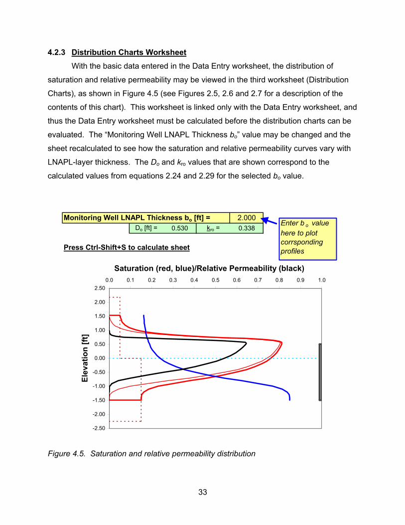
4.2.3 Distribution Charts Worksheet With the basic data entered in the Data Entry worksheet, the distribution of
saturation and relative permeability may be viewed in the third worksheet (Distribution
Charts), as shown in Figure 4.5 (see Figures 2.5, 2.6 and 2.7 for a description of the
contents of this chart). This worksheet is linked only with the Data Entry worksheet, and
thus the Data Entry worksheet must be calculated before the distribution charts can be
evaluated. The “Monitoring Well LNAPL Thickness bo” value may be changed and the
sheet recalculated to see how the saturation and relative permeability curves vary with
LNAPL-layer thickness. The Do and kro values that are shown correspond to the
calculated values from equations 2.24 and 2.29 for the selected bo value.
Monitoring Well LNAPL Thickness bo [ft] = 2.000Do [ft] = 0.530 kro = 0.338
Press Ctrl-Shift+S to calculate sheet
-2.50
-2.00
-1.50
-1.00
-0.50
0.00
0.50
1.00
1.50
2.00
2.500.0 0.1 0.2 0.3 0.4 0.5 0.6 0.7 0.8 0.9 1.0
Saturation (red, blue)/Relative Permeability (black)
Elev
atio
n [ft
]
Enter b o value here to plot corrsponding profiles
Figure 4.5. Saturation and relative permeability distribution

34
4.2.4 Well Worksheet Free-product recovery system analysis may be performed using worksheet 4 for
wells and worksheet 5 for a trench recovery system. First consider a recovery system
using wells and worksheet 4 (Well). The basic design variables required in this
worksheet are the recovery time, the recovery system (well) radius of capture, which is
a basic design variable as described in Charbeneau et al. (1999), and the LNAPL
dynamic viscosity. Separate sets of data are required for estimation of system
response and for specification of water enhanced and vacuum enhanced system
performance. The formation hydraulic conductivity and recovery well radius are
specified. These are used explicitly in calculation of LNAPL recovery using skimmer
wells. For water-enhanced and vacuum-enhanced systems, these data are used to
calculate response of the subsurface system to water/air production. If both the water
discharge and the wellhead suction pressure are set to zero, then a skimmer well is
assumed.
For a water-enhanced LNAPL recovery system the model requires the water
production rate and the screened interval of the aquifer. These are used directly in
calculation of the LNAPL recovery rate (see equation 3.1). To estimate the response of
the subsurface system to water production, the well radius of influence is also required.
This estimated value will not affect the predicted LNAPL recovery rates, but it is used to
calculate the drawdown at the well and the average drawdown within the radius of
capture. The drawdown at the well is calculated using the Thiem equation.
For a vacuum-enhanced LNAPL recovery system the model requires
specification of the wellhead suction pressure, the screened section of the vadose zone,
and an estimate of the air-phase relative permeability within the vadose zone. The
wellhead suction pressure is used to calculate the resulting air-phase production rate,
and these variables are used to calculate the LNAPL recovery rate using equation 3.2.
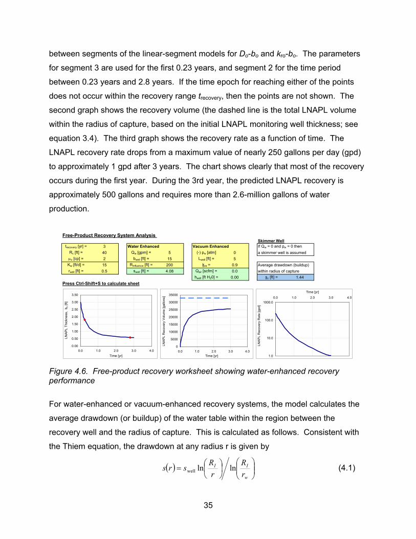
Figure 4.6 shows the parameters and output for the worksheet data of Figure 4.1
for a water-enhanced system producing 5 gallons per minute (gpm). The first graph
shows the LNAPL monitoring well thickness as a function of time. Two points are
marked (in red) on the LNAPL thickness chart. These points correspond to transition
35
between segments of the linear-segment models for Do-bo and kro-bo. The parameters
for segment 3 are used for the first 0.23 years, and segment 2 for the time period
between 0.23 years and 2.8 years. If the time epoch for reaching either of the points
does not occur within the recovery range trecovery, then the points are not shown. The
second graph shows the recovery volume (the dashed line is the total LNAPL volume
within the radius of capture, based on the initial LNAPL monitoring well thickness; see
equation 3.4). The third graph shows the recovery rate as a function of time. The
LNAPL recovery rate drops from a maximum value of nearly 250 gallons per day (gpd)
to approximately 1 gpd after 3 years. The chart shows clearly that most of the recovery
occurs during the first year. During the 3rd year, the predicted LNAPL recovery is
approximately 500 gallons and requires more than 2.6-million gallons of water
production.
Free-Product Recovery System Analysis
Skimmer Welltrecovery [yr] = 3 Water Enhanced Vacuum Enhanced If Qw = 0 and pw = 0 then
Rc [ft] = 40 Qw [gpm] = 5 (-) pw [atm] 0 a skimmer well is assumedµo [cp] = 2 bwell [ft] = 15 Lwell [ft] = 5Kw [ft/d] = 15 RInfluence [ft] = 200 kra = 0.9 Average drawdown (buildup)rwell [ft] = 0.5 swell [ft] = 4.08 Qair [scfm] = 0.0 within radius of capture
hwell [ft H20] = 0.00 sc [ft] = 1.44Press Ctrl-Shift+S to calculate sheet
0.00
0.50
1.00
1.50
2.00
2.50
3.00
3.50
0.0 1.0 2.0 3.0 4.0Time [yr]
LNAP
L Th
ickn
ess,
bo [
ft]
0
5000
10000
15000
20000
25000
30000
35000
0.0 1.0 2.0 3.0 4.0Time [yr]
LNAP
L R
ecov
ery
Volu
me
[gal
lons
]
1.0
10.0
100.0
1000.00.0 1.0 2.0 3.0 4.0
Time [yr]
LNAP
L R
ecov
ery
Rat
e [g
pd]
Figure 4.6. Free-product recovery worksheet showing water-enhanced recovery performance
For water-enhanced or vacuum-enhanced recovery systems, the model calculates the
average drawdown (or buildup) of the water table within the region between the
recovery well and the radius of capture. This is calculated as follows. Consistent with
the Thiem equation, the drawdown at any radius r is given by
( )
=
w
II
rR
rR
srs lnlnwell (4.1)

36
In equation 4.1, RI is the radius of influence of the well and swell is the drawdown at the
well. The average drawdown within the annulus between the well radius and the radius
of capture is calculated from
( ) ( )drrsrrR
sc
w
R
rwcc ∫−
= π2π
122 (4.2)
Substituting equation 4.1 into 4.2 and evaluating the integral one finds
( ) ( )( ) ( ) ( )
+
−
−= 222222
222222
well ln1
lnlnln
wIwIwc
wIwcIcc rRrRrR
rRrRRRss (4.3)
The same equation is used for the water table buildup with the vacuum-enhanced
system, with hwell replacing swell and it is assumed that RI = Rc for the vacuum-enhanced
system. Use of the average drawdown/buildup is discussed in Section 4.3.
For comparison with the water-enhanced system, Figure 4.7 shows the
performance of the same system using skimmer wells with a radius of capture of 15 feet
and for a recovery period of 5 years. The potential recovery is much less than shown in
Figure 4.5 because the radius of capture is smaller. During the recovery period the
LNAPL recovery rate decreases from about 40 gpd to just over 0.1 gpd at 5 years. As
suggested by Figure 4.4, reduction of LNAPL thickness below 0.6 feet using liquid
recovery will be very difficult because the LNAPL relative permeability has been
reduced to very low values.

37
Free-Product Recovery System Analysis Skimmer Well
trecovery [yr] = 5 Water Enhanced Vacuum Enhanced If Qw = 0 and pw = 0 thenRc [ft] = 15 Qw [gpm] = 0 (-) pw [atm] 0 a skimmer well is assumed
o [cp] = 2 bwell [ft] = 15 Lwell [ft] = 5Kw [ft/d] = 15 RInfluence [ft] = 200 kra = 0.9 Average drawdown (buildup)rwell [ft] = 0.5 swell [ft] = 0.00 Qair [scfm] = 0.0 within radius of capture
hwell [ft H20] = 0.0 sc [ft] = 0.00Press Ctrl-Shift+S to calculate sheet
0.00
0.50
1.00
1.50
2.00
2.50
3.00
3.50
0.0 1.0 2.0 3.0 4.0 5.0 6.0Time [yr]
LNAP
L Th
ickn
ess,
bo [
ft]
0500
100015002000250030003500400045005000
0.0 2.0 4.0 6.0Time [yr]
LNAP
L R
ecov
ery
Volu
me
[gal
lons
]
0.1
1.0
10.0
100.00.0 1.0 2.0 3.0 4.0 5.0 6.0
Time [yr]
LNAP
L R
ecov
ery
Rat
e [g
pd]
Figure 4.7. Free-product recovery worksheet showing skimmer well recovery performance 4.2.5 Trench Worksheet
Figure 4.8 shows results from worksheet 5 (Trench) for a trench recovery
system. The LNAPL lens is assumed to be 75 feet wide by 100 feet long in the direction
of natural groundwater flow. The natural groundwater gradient is 0.005. The trench has
a capture depth for groundwater of 5 feet. This value is used only in calculating the
additional gradient towards the trench caused by recovery of groundwater in addition to
LNAPL. It does not enter into calculation of LNAPL recovery rates. A groundwater
recovery rate of 2 gpm is assumed, which increases the hydraulic gradient towards the
lens by a small amount, which in turn, increases the LNAPL recovery rate by a small
amount. Comparing Figures 4.5, 4.6 and 4.7, the volume of free-product within the
capture zone of the system increases, as does the area size of the capture zone.
Considering trenches versus wells, the volume ratio is (LT WT)/(π Rc2). Most of the
LNAPL recovery occurs within the initial 2-year period. After about 6 years, the
recovery rate has decreased to less than 1 gpd.

38
Trench Recovery System
trecovery [yr] = 10Press Ctrl+Shift+S µo [cp] = 2to calculate sheet Qw [gpm] = 2
Jw = 0.005Kw [ft/d] = 15WT [ft] = 75LT [ft] = 100bT [ft] = 5
0.00
0.50
1.00
1.50
2.00
2.50
3.00
3.50
0 2 4 6 8 10 12Recovery Time [yr]
LNAP
L Th
ickn
ess
b o [f
t]
0
10000
20000
30000
40000
50000
60000
0 5 10 15Recovery Time [yr]
Rec
over
y LN
APL
Volu
me
[gal
lon]
0.1
1.0
10.0
100.0
1000.00 5 10 15
Recovery Time [yr]
LNAP
L R
ecov
ery
Rat
e [g
pd]
WT
LT
Jw
bo(t)Qo(t)
LNAPL Lens
Trench
Qw
Figure 4.8. Free-product recovery system performance for a trench system
All of the examples presented in this subsection have used the Burdine version of the
spreadsheet model [LNAPL (vG-B).xls]. All worksheets are the same for the Mualem
version of the model, whose use is discussed in Section 4.4.
4.3 LNAPL and Water Table Fluctuations
The formation LNAPL saturation distribution and monitoring well LNAPL
thickness will vary with water table fluctuations. If changes in water table elevation are
sufficiently slow, the condition of vertical equilibrium will not be compromised to a
significant extent, and the discussion presented in Section 2.1 describing the LNAPL
saturation distribution remain valid. It is of interest to investigate how Do and bo vary
with changes in elevation of the water table. To proceed in this investigation, consider
an LNAPL layer that has been spread (smeared) across a thickness from a lower
elevation zsz in the saturated zone beneath the free-product layer to an upper elevation
zvz in the vadose zone above the free product layer. Except within the free-product
layer, LNAPL is present at residual saturations in the vadose zone and saturated zone.
Using the notation from Section 2.1, the total LNAPL thickness is given by
( ) ( ) ( )maxorvszoworsLNAPL 0 zzSnDzzSnL vzo −++−= (4.4)

39
In equation 4.4, free product exists between elevations zow and zmax, the latter being
found using equation 2.23, and the specific free-product volume Do is given by equation
2.24. If the elevation of the water table changes by an amount ∆zwt due to groundwater
pumping, seasonal hydrologic budget, or other cause, without affecting the amount of
LNAPL present, then LLNAPL(∆zwt) = LLNAPL(0). Under the new conditions, which are
designated by addition of a prime, equation 4.4 becomes
( ) ( ) ( )
′−∆−+′+
∆−−′=∆ maxwtvzorvwtszoworswtLNAPL zzzSnDzzzSnzL o (4.5)
Setting the expressions in equations 4.4 and 4.5 equal and simplifying gives
( ) wtorvorsmaxorvoworsmaxorvowors zSSnzSnDzSnznSDznS oo ∆−+′−′+′=−+ (4.6)
The initial monitoring well thickness may be used with the spreadsheet to evaluate the
right side of equation 4.6. Then if ∆zwt is known, the spreadsheets may be used
iteratively to evaluate the new monitoring well LNAPL thickness, bo’, and free-product
thickness, Do’.
With the piecewise linear model equations, the calculation is made much simpler.
Equations 2.19 and 2.20 give zow = - �r bo, zao = (1 – ρr) bo, and bo = zao – zow. Using
these along with equation 2.25, equation 4.6 may be written
( ) ( ) ( ) wtorvorsχβγββχγβ zSSnbb oo ∆−+′′−′−′=−− (4.7)
Equation 4.7 may be solved directly for the new monitoring well thickness giving
( ) ( )( )γβχββχγβ wtorvors
−′∆−−′′+−−
=′ zSSnbb oo (4.8)
An example will highlight the significance of these results. Consider the initial
condition shown in Figure 2.2 with a monitoring-well LNAPL thickness of 2 feet. The
spreadsheet model gives zow = - 1.5 feet, zmax = 1.530 feet, and Do = 0.530 feet, so the
right side of equation 4.6 has the value 0.4094 feet. According to Figure 4.6, a water
production rate of 5 gpm results in an average drawdown of 1.44 feet within the 40-foot
radius of capture. If the water table is lowered by 1.44 feet (∆zwt = -1.44 ft), then n(Sors-
Sorv)∆zwt = -0.0576 feet. Thus the remaining terms on the right side (primed terms) have
a combined value of 0.4670 feet. Through trial and error, equation 4.6 is solved to find

40
b’o = 2.20 feet, zow = -1.650 feet, zmax = 1.670 feet, and Do = 0.599 feet. The initial
LNAPL saturation distribution and that predicted after the 1.44-feet decrease in water
table elevation are shown in Figure 4.1.
-4
-3
-2
-1
0
1
2
30 0.2 0.4 0.6 0.8 1
LNAPL SaturationE
leva
tion
[ft]
Initial Do = 0.530 ft
Final Do = 0.599 ft
1.44 ft
Figure 4.9. LNAPL saturation distribution before and after a 1.44-feet decrease in the water table elevation
Equation 4.8 provides a much simpler solution for finding the change in free-
product volume associated with a change in water table elevation. Figure 4.4 shows the
data table and fitted curves for the LNAPL-layer specific volume and relative
permeability. For an initial monitoring well thickness of 2 feet, the α and β values for the
third segment are used (α = 0.4635 and β = 0.345251). The new thickness is greater
than 2 feet so the same values are used for α’ and β’ (the appropriate parameter values
for the segment of the Do-bo model curve are used). The parameter γ equals 0.0500
(this parameter value is given on both the Well and Trench worksheets, immediately
below the charts). Using these values in equation 4.8 gives b’o = 2.195 feet and D’
o =
0.345251 (2.195 – 0.4635) = 0.5978 feet. These results are essentially the same as
found using the first method.
To account for the change in water table elevation due to groundwater pumping,
the LNAPL recovery would be calculated with a starting value bo = 2.2 feet rather than

41
bo = 2 feet. That is, the value bo = 2.2 feet would be entered for the Maximum
Monitoring Well LNAPL Thickness on the Data Entry worksheet shown in Figure 4.1.
4.4 Application of the Model to Fine-Grain Soils
Analysis of LNAPL recovery in fine-grain soils is important for a number of
reasons. The presence of fine-grain soils near the ground surface is common. The
effects of secondary porosity often dominate the hydraulics and transport characteristics
of these soils. Furthermore, strong vertical hydraulic gradients are often present.
These latter two characteristics are contrary to the assumptions on which the LNAPL
recovery model is based (homogeneous soils and vertical equilibrium), and these
characteristics may result in “unusual” distributions of LNAPL. For these reasons,
discussion of fine-grain soils deserves separate attention.
Primary porosity refers to the original porosity of the porous medium upon
deposition. Secondary porosity refers to that portion of the total porosity resulting from
diagenetic processes such as dissolution, stress fractures, desiccation cracks, animal
burrows, root holes, or other causes. In fine-grain soil the magnitude of secondary
porosity (usually called macropores) is usually much smaller than primary porosity,
though its existence may dominate the hydraulic characteristics of the porous medium.
The length-scale (pore size) associated with the primary porosity is much smaller than
that of the secondary porosity. Thus, according to the Laplace equation 2.2, LNAPL
can enter the secondary porosity (macropores) at a much smaller capillary pressure
then would be required for entrance into the primary porosity (the fine-grain porous
matrix). If the secondary porosity forms a continuous porous network, then LNAPL can
migrate through this secondary porosity domain, independent of the existence of the
primary porosity domain. This can result in unusual distributions and migration patterns
for LNAPL.
The presence of strong vertical gradients through fine-grain soil layers is
expected near regions of groundwater recharge, especially under conditions where
there is an underlying permeable layer. The downward gravitational hydraulic gradient
within the vadose zone is 1. When infiltration reaches the water table, it will move both

42
vertically and horizontally following the hydraulic path of least resistance. With an
underlying permeable layer, this path is generally downward, and movement of
recharge water through the fine-grain layer (with low permeability) requires a strong
downward gradient. Downward vertical gradients may be one to three orders of
magnitude larger than horizontal gradients.
4.4.1 Conceptual Model for LNAPL Distribution in Fine-Grain Soil First consider the potential depth of LNAPL penetration below the water table in
fine-grain soil. The schematic in Figure 4.10 shows an LNAPL source zone located a
distance Zo above the water table. LNAPL has entered the macropore system and
migrated downward to a depth Z below the water table. At point B located at this depth
Z below the water table, the water and LNAPL pressure are the same (there is
negligible capillary pressure within the macropore because of its size). The pressure
through the LNAPL may be calculated using hydrostatics, while the water pressure must
consider the downward movement of percolating water under a hydraulic gradient Jz.
Equating the pressures at point B gives the following relationship:
ozr
r ZJ
Z
−−
=ρ1ρ (4.9)
Equation 4.9 shows that in particular, if Jz > 1 – ρr, then the hydraulic gradient will
carry the LNAPL down to the underlying permeable zone where the vertical hydraulic
gradient should be dissipated.

43
Jz
Zo
Z
B
Ground Surface
LeakingTank
WaterTable
MacroporeSystem
Depth ofLNAPL
Penetration
HydraulicGradient
Figure 4.10. Schematic view of LNAPL distribution in macropores
Equation 4.9 suggests that LNAPL can penetrate to considerable depths within
macropores of a fine-grain soil. If the macropores are in direct communication with a
monitoring well, then the same LNAPL thickness will be observed in the well. However,
because LNAPL is confined to the macropores, the overall LNAPL saturation remains
very low. This is one of the unusual features of fine-grain soils. One may expect to find
large LNAPL thickness in monitoring wells with adjacent soils having very low LNAPL
saturation.
4.4.2 Characterization of a Fine-Grain-Soil Site
Data was provided for a site located in the Midwestern United States (Adamski et
al., 2003). At this location, the subsurface consists of about 27 feet of homogeneous

44
fine-grain soil overlying a thin, discontinuous layer of weathered bedrock and
competent, relatively impermeable shale/sandstone bedrock. The depth to groundwater
is generally 7 to 10 feet below-ground-surface (bgs). The downward vertical gradient
through the fine-grain soil ranges from 0.10 to 0.30, while the horizontal gradient is 0.08.
LNAPL has been observed in macropores and permeable zones as deep as 17 feet
below the water table. LNAPL accumulations in excess of 15 feet have been measured
in observation wells.
Water retention data were obtained in the laboratory for a fine-grain soil boring
from the site. The van Genuchten model parameters N, α, and Swr were fit to this data,
with the soil characteristics curve shown in Figure 4.11. The resulting parameters are
N = 1.46, α = 0.17 ft-1, and Swr = 0.69. The saturated water content (porosity) is
n = 0.433. Very large suction pressures are required to displace water from the fine-
grain soil.
0.1
1
10
100
0.7 0.8 0.9 1Water Saturation
Cap
illar
y P
ress
ure
Hea
d (ft
)
Figure 4.11. Fine-grain soil characteristic curve showing measured data with fitted van Genuchten model (N = 1.46, � = 0.17 ft-1, and Swr = 0.69)
The LNAPL at this site is a non-volatile weathered diesel. Separate
measurements were made of interfacial tension values (σaw = 66 dyne/cm, σow = 20
dyne/cm, σao = 31 dyne/cm), LNAPL density (ρo = 0.91 g/cm3), and LNAPL viscosity (µo

45
= 6.3 cp). Analysis of slug test data suggests that the hydraulic conductivity is
approximately 0.01 ft/d.
LNAPL saturation values were measured for soil borings located above and
below the water table. Eleven analyses were conducted resulting in eight samples
without detectable LNAPL, two samples with LNAPL at 0.1% saturation, and one
sample with LNAPL at 1.4% saturation (the largest value observed). That most of the
samples had no detectable LNAPL might have been expected, because LNAPL is
confined to the macropores, and the macropores are spaced through the domain. If
macropores are sufficiently sparse, most of the randomly placed soil borings would not
contain macropores and associated LNAPL. The field-measured data was input to the
model for LNAPL distribution, and the resulting profile is shown in Figure 4.12, where
the LNAPL distribution corresponds to a LNAPL monitoring well thickness of bo = 10
feet. Residual vadose zone and saturated zone LNAPL saturation values are assumed
to be zero. This is consistent with the soil borings having no detectable LNAPL. Soil
boring data was available in terms of depth bgs. For this figure, it is assumed that the
water table is located 7 feet bgs. Perhaps the most significant feature of merit from this
figure is that a maximum model-predicted LNAPL saturation of about 2 - 3% is not
unreasonable based on the site-specific data, and that this is consistent with monitoring-
well LNAPL thickness of about 10 feet.
-10.0
-8.0
-6.0
-4.0
-2.0
0.0
2.0
4.00.00 0.01 0.02 0.03 0.04 0.05
LNAPL Saturation
Elev
atio
n [ft
]

46
Figure 4.12. LNAPL distribution in fine-grain soil with macropores
The Mualem (1976) model is used to predict the relative permeability distribution.
This model was developed using cut and rejoin concepts, and Mualem assumed that
pore lengths are proportional to pore radii, which results in large pores having “a more
important influence than is generally assumed.” Use of the Burdine model with these
small saturation values will result in essentially zero relative permeability and no LNAPL
flow.
A total fluids extraction (TFE) system has been in operation at the site. The
recovery system consists of a two-inch well removing air, water and LNAPL, extracted
with suction applied via a liquid ring pump. The system applies a vacuum of about 26
inches of mercury to the well (approximately 0.85 atmospheres suction). The screen
length of the recovery well is 20 feet. During recovery, the initial airflow rate was 65
standard ft3/minute (scfm). The initial LNAPL thickness in monitoring wells located near
the extraction well varied from 0.55 feet to 15.3 feet.
The spreadsheet model was applied to simulate LNAPL recovery as a vacuum-
enhanced system. All measured data were used. An effective radius of capture of 20
feet was assumed, and it is assumed that the average initial LNAPL thickness within
this radius is 8 feet. Using this data and a 1-year recovery period, the model predicts
recovery of only 40 gallons out of a potential recovery of 390 gallons within the radius of
capture. This is compared to the measured recovery of 150 gallons. The reason for the
small recovery is the hydraulic conductivity value that is used. Even with a suction
pressure of 0.85 atmospheres, the model calculates an air discharge of 0.3 scfm.
Increasing the hydraulic conductivity value to 2.55 ft/d (more than a two-order-of-
magnitude increase), the predicted air discharge is 65 scfm, which is the same as the
initial air discharge from the recovery system. Figure 4.13 shows the resulting
measured and predicted LNAPL recovery. The predicted recovery is more than twice
as large as the measured recovery after 1 year.

47
0.0
50.0
100.0
150.0
200.0250.0
300.0
350.0
400.0
450.0
0.0 0.5 1.0 1.5
Time [yr]
LNAP
L R
ecov
ery
Volu
me
[gal
lon]
Figure 4.13. Comparison of measured and predicted LNAPL recovery
The objective of this exercise is to show that the model can be applied using
measured field data, and that useful results for design and analysis of LNAPL recovery
systems can be obtained. Much better fit to the observed recovery data can be
achieved with the model by adjusting parameters. Figure 4.14 shows that excellent
agreement can be achieved with a radius of recovery Rc = 12.5 feet and a hydraulic
conductivity of 1.9 ft/d. However, it is recognized that this excellent fit verifies neither
the model nor the parameter values.
0.0
20.0
40.0
60.0
80.0
100.0
120.0
140.0
160.0
0.0 0.5 1.0 1.5
Time [yr]
LNAP
L R
ecov
ery
Volu
me
[gal
lon]
Figure 4.14. Calibrated model with Rc = 12.5 ft and Kw = 0.25 ft/d

48
4.4.3 Discussion
This is a good point to clarify one aspect of the liquid free-product hydrocarbon
recovery model. Looking at Figure 4.13, it appears that an obvious parameter change
for obtaining a better fit between the predicted and measured recovery would be to
change the LNAPL residual saturation values. However, the effects this will have may
not be expected because the capillary pressure head is the primary variable, rather than
the LNAPL saturation. Equations 2.8 and 2.10 show that the capillary pressure head at
a specified elevation is a function of the elevation of the LNAPL-water and air-LNAPL
interfaces in a monitoring well. Based on the capillary pressure head, scaling relations
are used to calculate the water (equation 2.13) and total liquid (equation 2.14)
saturation values. Changing the residual LNAPL saturation values for the vadose zone
and saturated zone will change the total saturation values as well.
The effect of changing the vadose zone and saturated zone residual LNAPL
values from zero to Sorv = 0.002 and Sors = 0.008 are shown in Figure 4.15. The figure
to the left shows the LNAPL saturation and relative permeability distributions. Two
curves are shown for the LNAPL saturation. The curve with smaller saturation values
has zero-residual values, and is used to calculate the relative permeability distribution.
This is the same distribution that was used to predict the recovery shown in Figure 4.13.
The second LNAPL saturation curve with larger values is used to estimate specific
storage and potential recovery. The right side of Figure 4.15 shows the predicted
LNAPL recovery. Compared with Figure 4.14, the potential recovery is seen to increase
significantly, while the actual predicted recovery also increases compared with results
from the model with zero residual saturation values.

49
-8.0
-6.0
-4.0
-2.0
0.0
2.0
4.00.00 0.05 0.10 0.15
Saturation/Relative PermeabilityEl
evat
ion
[ft]
Relative Permeability
0.0
50.0
100.0
150.0
200.0
250.0
300.0
0.0 0.5 1.0 1.5
Time [yr]
LNAP
L R
ecov
ery
Volu
me
[gal
lon]
Figure 4.15. LNAPL saturation, relative permeability, and recovery curves for a model
simulation with positive LNAPL residual saturation values
4.5 Model Implementation
This liquid free-product recovery model is implemented within an Excel workbook
through definition of a number of functions for performing the separate calculations.
These functions along with their arguments are listed in Appendix B along with a brief
description of the task that each function is performing. [Unlike Fortran or C functions, a
function in Visual Basic is meant to only return a single numerical or logical value to the
calling spreadsheet cell.]

50

51
SECTION 5 – REFERENCES
Adamski, M., Kremesec, V., Kolhatkar, R., Pearson, C., and Rowan, B., LNAPL in Fine-Grained Soils: Conceptualization of Saturation, Distribution, Recovery and Their Modeling, Ground Water Monitoring & Remediation, 2003 (Submitted). Brooks, R.H. and Corey, A.T., Hydraulic Properties of Porous Media, Hydrol. Pap. 3, Colo. State Univ., Fort Collins, 1964. Burdine, N.T., Relative Permeability Calculations from Pore-size Data, Trans. A.I.M.E. 198, 71-77, 1953. Carsell, R.F. and Parish, R.S., Developing Joint Probability Distributions of Soil Water Retention Characteristics, Water Resources Research, 24(5), 755-769, 1988. Charbeneau, R.J., Johns, R.T., Lake, L.W., and McAdams III., M.J., Free-Product Recovery of Petroleum Hydrocarbon Liquids, American Petroleum Institute Publication Number 4682, Washington D.C., June 1999. Charbeneau, R.J., Johns, R.T., Lake, L.W. and McAdams III, M.J., Free-product Recovery of Petroleum Hydrocarbon Liquids, Ground Water Monitoring and Remediation, 20(3), 147-158, 2000. Charbeneau, R.J., Groundwater Hydraulics and Pollutant Transport, Prentice Hall, Upper Saddle River, N.J., 2000. Johns, R.T., L.W. Lake, A.B. Obigbesan, L. Bermudez, M.R. Hassan and Charbeneau, R.J., Analytical Solutions for Free-product Recovery using Skimmer and Dual-pump Wells, Ground Water Monitoring and Remediation, 23(1), 97-106, 2003. Lenhard, R.J., Parker, J.C., and Mishra, S., On the Correspondence between Brooks-Corey and van Genuchten Models, Journal of Irrigation and Drainage Engineering, 15(4), 744-751, 1989. Leverett, M.C., Capillary Behavior in Porous Media, Trans. A.I.M.E. 142, 341-358, 1941. Mualem, Y., A New Model for Predicting the Hydraulic Conductivity of Unsaturated Porous Media, Water Resources Research, 12, 513-522, 1976. van Genuchten, M.T., A Closed-form Equation for Predicting the Hydraulic Conductivity of Unsaturated Soil, Soil Sci. Soc. Am. J., vol. 44, 892-898, 1980.

52

53
APPENDIX A – HETEROGENEOUS SYSTEM
A.1 Introduction
In this appendix, the LNAPL free-product recovery models are extended for a
simple case of aquifer heterogeneity where a soil layer of one texture overlies a layer
with a differing texture, with an abrupt interface separating the layers. This case of soil
heterogeneity is shown in Figure A.1. This figure shows a monitoring well with an
LNAPL layer located between the air-NAPL interface zao and the NAPL-water interface
zow. The total monitoring well thickness is bo (not shown). The elevation of the water
table, zaw, provides the datum for fluid levels. While the water table is not present
because of the LNAPL layer, its elevation is easily determined from the elevations zao
and zow, and the LNAPL density ρo. For the example shown in Figure A.1, the abrupt
facies interface between the upper Layer 1 and the lower Layer 2 is at elevation z12
located beneath the water table. This interface could be located above, below, or at the
water table, and the texture characteristics of each layer and there contrast across the
interface will strongly influence the resulting LNAPL saturation distribution. Figure A.1
should be compared with Figure 1.1.
Water Tablezao
zow
Facies Interface
z12
Layer 1 (Upper)
Layer 2 (Lower)
zaw
LNAPLLayer
Figure A.1. Simple heterogeneity (abrupt facies interface) in subsurface porous media

54
For the heterogeneous soil system, the texture characteristics that must be
defined for each layer include the porosity n, the van Genuchten parameters N and α,
the irreducible water saturation Swr, and the residual LNAPL saturation values for the
vadose zone and saturated zone, Sorv and Sors. Fluid properties include the LNAPL
density ρo (it is assumed that the water density is 1 g/cm3), and the water and LNAPL
surface and interfacial tensions, σaw, σao, and σow.
A.2 Capillary Pressure Relationships
Equation 2.1 and appropriately scaled capillary pressure relationships are still
used to describe the vertical distribution of fluid saturation, based on the assumption of
vertical equilibrium. The pressure in each phase satisfies the hydrostatic pressure
equation. Appreciation of this requirement is especially important when one considers
porous media with abrupt changes in soil texture; the capillary pressure must remain
continuous across an abrupt facies change, even though this results in an abrupt
change in fluid saturation.
A.2.1 Saturation and Specific Volume for Heterogeneous Media
A simple case of aquifer heterogeneity is the condition where a soil layer of one
texture overlies a layer with a differing texture, with an abrupt interface separating the
layers. With the van Genuchten soil characteristic model, the parameters that must be
specified include those for the upper layer, n1, N1, α1, Swr1, Sorv1, Sors1, K1, those for the
lower layer, n2, N2 and a2, Swr2, Sorv2, Sors2, K2, and the elevation of the interface
between the layers, z12. Within this appendix and model description, layer 1 is the
upper layer and layer 2 is the lower soil layer. Requirements from fluid mechanics
dictate that under conditions of vertical equilibrium, the hydrostatic pressure remains
continuous across the interface between the two layers, and that the fluid saturations
adjust abruptly to local soil characteristic properties. This results in a discontinuity in
fluid saturation values. Equations 2.13, 2.14 and 2.15 are applicable for both layers
when appropriate layer-specific parameter values are used, and equation 2.24 may still

55
be used to calculate the specific free-product volume, Do. The elevations zow and zao
are independent of soil texture (see equations 2.19 and 2.20), while the elevation of zmax
depends on local soil-texture properties.
As an example, Figure A.2 shows the water and LNAPL saturation distribution for
conditions with an upper soil layer having properties n1 = 0.40, N1 = 1.5, α1 = 0.5 ft-1,
Swr1 = 0.60, Sorv1 = 0.05, Sors1 = 0.10, and lower soil layer having properties n2 = 0.35,
N2 = 4.0, α2 = 2.0 ft-1, Swr2 = 0.10, Sorv2 = 0.10, Sors2 = 0.20. The elevation of the
interface between these layers is z12 = -0.40 feet. These properties correspond to the
lower layer having a coarser soil texture than the upper layer, with an abrupt change in
water saturation across the interface between the lower and upper layers. The LNAPL
specific volume for the monitoring well thickness bo = 2 feet is Do = 0.295 feet. This
compares with a specific volume Do = 0.499 feet which is found if the soil profile is
homogeneous with properties corresponding to the lower soil layer and Do = 0.158 feet.
-3.00
-2.00
-1.00
0.00
1.00
2.00
3.00
4.000.0 0.2 0.4 0.6 0.8 1.0
Fluid Saturation
Elev
atio
n [ft
]
Residual LNAPL (Vadose Zone)
Water Table
Residual LNAPL (Saturated Zone)
LNAPL
LNAPL
Water
Water
Soil Texture Interface
Monitoring Well LNAPL Thickness
Figure A.2. LNAPL and water distributions for heterogeneous soil with properties corresponding to coarse texture layer overlying fine texture layer. Monitoring well LNAPL thickness equals 2 feet.

56
A.2.2 LNAPL-Layer Relative Permeability The presence of soil heterogeneity can have a significant effect on the LNAPL-
layer relative permeability function. Figure A.3 shows the relative permeability curve for
the Mualem model for the conditions of Figure A.2 and for two homogeneous cases with
coarse and fine-textured layers. The curve with triangle symbols corresponds to
conditions shown in Figure A.2. The curve with diamond symbols is for a homogeneous
soil with properties of the upper fine-grain soil in Figure A.2, while the curve with square
symbols is for a homogeneous soil with properties of the lower coarse-texture soil. For
small lens thickness, the lens is situated only in the fine-texture soil, and the relative
permeability is the same as would be found for a homogenous fine-texture soil. Once
the LNAPL-layer thickness exceeds about 1.2 feet, a significant part of the lens exits in
the coarse-texture soil with larger saturation values and a higher effective LNAPL-layer
relative permeability. Thus the curve rises above that of the homogeneous fine-texture
soil.
0
0.1
0.2
0.3
0.4
0.5
0.6
0.7
0.8
0.0 1.0 2.0 3.0 4.0
LNAPL-Layer Thickness, bo [f t]
LNAP
L-La
yer R
elat
ive
Perm
eabi
lity
Figure A.3. LNAPL-layer relative permeability function for homogeneous coarse-texture soil (square), heterogeneous soil with fine-texture soil overlying coarse-texture soil (triangle), and homogeneous soil with fine-texture (diamond).

57
A.2.3 Spreadsheet Models for Heterogeneous Soil
The models described in Sections 3 and 4 have been also been implemented for
heterogeneous soils through two separate and standalone spreadsheets: LNAPL (vG-
B-2L).xls and LNAPL (vG-M-2L).xls. These are the two layer versions of the
spreadsheet models described in Section 4, and the description remains basically the
same except that additional soil texture data is required for the Data Entry sheet. For
example, Figure A.4 shows the Data Entry worksheet used to develop Figure A.2.

58
van Genuchten-Mualem ModelEnter Data in Yellow RegionMaximum Monitoring WellLNAPL Thickness [feet]
bo = 3.000
Fluid Characteristics:ρo = 0.850 LNAPL density [gm/cc]
σaw = 65.000 air/water surface tension [dyne/cm]σao = 25.000 air/LNAPL surface tension [dyne/cm]
σow = 15.000 LNAPL/water surface tension [dyne/cm]
Soil Characteristics:z12 = -0.4 elevation of soil facies interface [ft]
Soil Layer 1 (Upper)n1 = 0.400 porosity
N1 = 1.500 van Genuchten "N"
α1 = 0.500 van Genuchten "α" [ft-1]Swr1 = 0.600 irreducible water saturationSorv1 = 0.050 residual LNAPL saturation (vadose)Sors1 = 0.100 residual LNAPL saturation (saturated)
Soil Layer 2 (Lower)n2 = 0.350 porosity
N2 = 4.000 van Genuchten "N"
α2 = 2.000 van Genuchten "α" [ft-1]Swr2 = 0.100 irreducible water saturationSorv2 = 0.100 residual LNAPL saturation (vadose)Sors2 = 0.200 residual LNAPL saturation (saturated)
Figure A.4. “Data Entry” worksheet showing data leading to Figure A.2 A.2.4 Model Implementation: Specific Retention and Hydraulic Contuctivity
There are two areas for which the model implementation must be modified to
address the condition with heterogeneous soils with two layers having different soil
texture properties. Because the LNAPL layer thickness changes through time during
recovery operations, the LNAPL layer specific retention and effective hydraulic
conductivity may also change. First consider the necessary modifications to address
LNAPL volume and specific retention.

59
Equations 3.5, 3.6 and 3.7 must be modified for heterogeneous soil profiles. If
zao > z12 > 0 [bo > z12/(1-ρr)] then equation 3.5 becomes
( ) ( )[ ]owors2212orv2212aoorv112
or π zSnzSnzzSnRbV co −+−=
This equation may be re-written as
( ) ( )[ ] ( ){ }12orv11orv222ors2orv112 ρρ1π zSnSnbSnSnRbV orrcoor −++−= (A.1)
If z12 > zao [bo < z12/(1-ρr)] then equation 3.5 is appropriate with porosity and residual
saturation values corresponding to layer 2. If 0 > z12 > zow [bo > -z12/ρr], then equation
3.5 takes the form
( ) ( )[ ]ow12ors2212ors11aoorv112
or π zzSnzSnzSnRbV co −+−=
Again, this equation may be re-written in the following form
( ) ( )[ ] ( ){ }12ors11ors22ors22orv112
or ρρ1π zSnSnbSnSnRbV orrco −++−= (A.2)
If z12 < zow [bo < -z12/ρr] then equation 3.5 is appropriate with porosity and residual
saturation values corresponding to layer 1.
For the general case, when combined with equation 2.25, equation 3.6 may be
written
( ) ( ) δγβπ ij2 +−= ocoo bRbV (A.3)
where δ is a constant and
( ) orsjorviij ρρ1γ SnSn jrir +−= (A.4)
The parameter γij plays the same role in continuity for the LNAPL layer as the specific
retention plays in continuity at the water table of an unconfined aquifer, as the water
level rises and falls. In this regard, (β – γij) plays the role of the specific yield
(Charbeneau, 2000).
Most of the workbook calculations are straightforward and are based on the
equations presented in Sections 2 and 3. However, calculations for both the skimmer
well and trench require the medium hydraulic conductivity value, and for the two-facies
heterogeneous model, its specification is problematic. Effects of two facies show up in
two different parts of the calculations. Characteristics of soil texture that are
represented by van Genuchten parameter values are implicitly included within the

60
functions Do(bo) and kro(bo), and there fitted linear-segment models. However, the value
of Kw also appears explicitly in both models.
One approach for dealing with variation in Kw with bo would be to explicitly
include it in calculation of the permeability distribution, so that one would calculate
Ko(bo) rather than kro(bo). However, the additional contrast with including Kw variations
in this function would make convergence of the approximating integrals to evaluate lens
properties especially difficult (more so than the already included soil texture properties,
as shown in Figure 4.4, for example). This approach has not been selected. Instead,
variations in effective Kw values are included in the following ‘ad hoc’ fashion.
Effect of variation in Kw is directly related to the facies contact with the monitoring
well LNAPL-thickness. This allows one to calculate an effective transmissivity, just as
one would for a stratified aquifer with horizontal flow. If the facies discontinuity horizon
lies within the range zow-zao, as shown in Figure A.1, then the effective hydraulic
conductivity is calculated from
( ) ( )( ) ow bKzzKzzK /w2ow12w112ao −+−= (A.5)
An added difficulty in calculation of free-product recovery rates is that wK varies with
LNAPL-layer thickness. Without explicitly including this effect, it is included in the
recovery rate equations by using an effective hydraulic conductivity calculated from
( ) ( ) ( )2121, owowoow bKbKbbK = (A.6)
Equation A.6 states that the effective hydraulic conductivity over a time period during
which the LNAPL-layer thickness decreases from bo1 to bo2 is equal to the geometric
mean value of the endpoint values.

61
APPENDIX B – VISUAL BASIC FUNCTION CALLS
Function bot(t, t3, t2, t1, bo1, bo2, bo3, b1, b2, b3, x2, x3, h1, h2, h3, _ aw, aa, ask, ro, z12, por1, sorv1, sors1, por2, sorv2, sors2, _ kw1, kw2) 'Determine monitoring-well LNAPL thickness at time t '--------------------------------------------------- ' t2 -> bo2 : t1 -> bo1 : t3 -> bz : x1 = 0 Function bo_trench(t, t3, t2, t1, bo1, bo2, bo3, b1, b2, b3, x2, x3, _ h1, h2, h3, ro, z12, por1, sorv1, sors1, por2, _ sorv2, sors2, kw1, kw2, dft, lt, jw, mo) 'Determine monitoring-well LNAPL thickness at time t '--------------------------------------------------- 't2 -> bo2 : t1 -> bo1 : t3 -> bz : x1 = 0 'dft = qt / (2 * wt * bt) Darcy flux into trench Function elev(index, bo, ro, z12, N1, aao1, aow1, swr1, sorv1, sors1, _ N2, aao2, aow2, sw2, sorv2, sors2) 'This function sorts out the elevation data for plotting saturation 'and permeability profiles. The key elevations are zow, zao, zmax, and 'z12. Depending on the magnitude of z12 compared with the others, there 'may be two or three segments to the profile. Function gg(bo, ro, z12, por1, sorv1, sors1, por2, sorv2, sors2) 'Calculate the specific retention parameter "gamma" Function hycon(bo, ro, z12, kw1, kw2) 'Calculate the average water hydraulic conductivity corresponding 'to LNAPL thickness bo, LNAPL density ration ro, and facies 'interface elevation z12 in same units as kw1 and kw2 Function kro(z, bo, ro, z12, N1, aao1, aow1, swr1, N2, aao2, aow2, swr2) 'Calculate the LNAPL relative permeability at elevation z using the 'Burdine equation Function krob(bo, ro, z12, N1, aao1, aow1, swr1, N2, aao2, aow2, _ swr2, Eps_kro) 'Evaluate the LNAPL-layer relative permeability Function kro_b(bo, bo1, bo2, x2, x3, h1, h2, h3) 'Determine LNAPL layer relative permeability based on bo using the 'piecewise linear model and parameters from the "Layer Calcs" worksheet Function qair(ha, lw, kra, kw1, kw2, rw, rc, z12) 'Calculation of the well pressure due to vapor-enhanced recovery

62
Function sw(z, bo, ro, z12, N1, aow1, swr1, sors1, N2, aow2, swr2, sors2) 'Calculate the water saturation at elevation z Function so(z, bo, ro, z12, N1, aao1, aow1, swr1, sorv1, sors1, N2, aao2, _ aow2, swr2, sorv2, sors2) 'Calculate the LNAPL saturation at elevation z Function swell(qw, bw, kw1, kw2, z12, ri, rw) 'Calculate the drawdown at the well due to aquifer pumping Function tmrec(index, t1, t2, t3, trec) 'Order the sequence of times t1, t2, t3 and trecovery. 'Return the time corresponding to "index", with 10 'increments between each time epoch. Function tt1(bo1, bo2, b2, x2, h2, aw, aa, ask, t2, ro, z12, por1, sorv1, _ sors1, por2, sorv2, sors2, kw1, kw2) 'Time to end of second segment of performance curve. Check whether 'interface z12 is reached. Function tt2(bo2, bo3, b3, x3, h3, aw, aa, ask, ro, z12, por1, sorv1, _ sors1, por2, sorv2, sors2, kw1, kw2) 'Time to end of first segment of performance curve. Check whether 'interface z12 is reached. Function tt3(bo1, bo2, bo3, b1, b2, b3, x2, x3, h1, h2, h3, aw, aa, ask, _ ro, z12, por1, sorv1, sors1, por2, sorv2, sors2, kw1, kw2) 'Return the time at which the LNAPL interface, determined by bo, reaches 'the elevation of the facies-change interface z12 Function tt1_trench(bo1, bo2, b2, x2, h2, t2, ro, z12, por1, sorv1, sors1, _ por2, sorv2, sors2, kw1, kw2, qt, lt, wt, bt, jw, mo) 'Time to end of second segment of performance curve (bo2 -> bo1). Check 'whether interface z12 is reached. Function tt2_trench(bo2, bo3, b3, x3, h3, ro, z12, por1, sorv1, sors1, _ por2, sorv2, sors2, kw1, kw2, qt, lt, wt, bt, jw, mo) 'Time to end of initial segment of performance curve (bo3 -> bo2). Check 'whether interface z12 is reached. Function tt3_trench(bo1, bo2, bo3, b1, b2, b3, x2, x3, h1, h2, h3, ro, z12, _ por1, sorv1, sors1, por2, sorv2, sors2, kw1, kw2, qt, _ lt, wt, bt, jw, mo) 'Return the time at which the LNAPL interface, determined by bo, reaches 'the elevation of the facies-change interface z12

63
Function vo(bo, ro, z12, por1, N1, aao1, aow1, swr1, sorv1, sors1, _ por2, N2, aao2, aow2, swr2, sorv2, sors2, Eps_Do) 'Evaluate the LNAPL specific volume corresponding to bo Function vorecov(bo, bo1, bo2, bo3, b1, b2, b3, ro, z12, por1, sorv1, _ sors1, por2, sorv2, sors2) 'Calculate the LNAPL recovery volume due to reducing the LNAPL 'thickness from bo3 to bo Function zmax(bo, ro, z12, N1, aao1, aow1, swr1, sorv1, sors1, N2, aao2, _ aow2, swr2, sorv2, sors2) 'Calculate the maximum elevation of free LNAPL

64

65
APPENDIX C – REPRESENTATIVE VAN GENUCHTEN MODEL PARAMETERS
(AFTER CARSELL AND PARISH, 1988) Soil type sample Saturated Water Content, q m Residual Water Content, q wr van Genuchten N van Genuchten a (ft -1) Hydraulic Conductivity K ws (ft/d)
size mean std. dev. mean std. dev. mean std. dev. mean std. dev. sample size mean std. dev.
Clay 400 0.38 0.09 0.068 0.034 1.09 0.09 0.24 0.37 114 0.16 0.33
Clay Loam 364 0.41 0.09 0.095 0.010 1.31 0.09 0.58 0.46 345 0.20 0.56
Loam 735 0.43 0.10 0.078 0.013 1.56 0.11 1.1 0.64 735 0.82 1.44
Loamy Sand 315 0.41 0.09 0.057 0.015 2.28 0.27 3.8 1.3 315 11 8.9
Silt 82 0.46 0.11 0.034 0.010 1.37 0.05 0.49 0.21 88 0.20 0.26
Silt Loam 1093 0.45 0.08 0.067 0.015 1.41 0.12 0.61 0.37 1093 0.36 0.98
Silty Clay 374 0.36 0.07 0.070 0.023 1.09 0.06 0.15 0.15 126 0.016 0.085
Silty Clay Loam 641 0.43 0.07 0.089 0.009 1.23 0.06 0.30 0.18 592 0.056 0.15
Sand 246 0.43 0.06 0.045 0.010 2.68 0.29 4.4 0.88 246 23 12
Sandy Clay 46 0.38 0.05 0.100 0.013 1.23 0.10 0.82 0.52 46 0.095 0.22
Sandy Clay Loam 214 0.39 0.07 0.100 0.006 1.48 0.13 1.8 1.2 214 1.0 2.2
Sandy Loam 1183 0.41 0.09 0.065 0.017 1.89 0.17 2.3 1.1 1183 3.6 4.6

66

67
APPENDIX D – REPRESENTATIVE FLUID PROPERTIES
Interfacial and Surface Tension (dynes/cm) at 20o C
(From Charbeneau, et al. 1999. Free-Product Recovery of Petroleum Hydrocarbon Liquids. API Publication 4682)
Chemical Name Interfacial Tension Surface Tension
Benzene 35 28.9 Ethylbenzene 35.5 29.3
Toluene 36.1 28.5 o-Xylene 36.1 30.3 Crude Oil no data 24-38
Diesel Fuel 50 25 Gasoline 50 21
Naptha (BTX mixture) 45 20 Fuel Oil No. 1 48 27
Jet Fuel JP-4/5 50 25 Petroleum Distillates 50 21
Source: Mercer, J.W. and Cohen, R. M., A Review of Immiscible Fluids in the Subsurface, Journal
of Contaminant Hydrology, Vol. 6, pp. 107-163, 1990.
Laboratory measurements show that the values of both the surface and the interfacial tensions of a crude oil extend over a wide range of values, from 2 dyne/cm to 30 dyne/cm. A value of 25 dyne/cm is commonly used for both surface (σao ) and interfacial (σow ) tensions of a crude oil. Measurements show that for an unleaded gasoline with 7% MTBE, the interfacial tension is 35.1 dyne/cm (Charbeneau and Chiang, 1995). In the laboratory, the surface tension for water in contact with air is σaw = 72 dyne/cm. In soil, some chemicals will accumulate at the interface between water and air, reducing the surface tension, and an effective air-water surface tension of 65 dyne/cm is often assumed.
Additional information about interfacial tension values can be found in:
Kolhatkar R; Kremesec V, Rubin S, Yukawa C, Senn R. Application Of Field And Analytical Techniques To Evaluate Recoverability Of Subsurface Free Phase Hydrocarbons Proceedings Of The Petroleum Hydrocarbons And Organic Chemicals In Ground Water: Prevention, Detection, And Remediation; Conference And Exposition, November 17-19, 1999, Houston, Texas; p5-15.
LNAPL Parameters Database to be published by API in 2003. (Check www.api.org/lnapl for availability)

68
APPENDIX D – REPRESENTATIVE FLUID PROPERTIES (cont.)
Representative LNAPL Density Values (gm/cm3)
(From Charbeneau, et al. 1999. Free-Product Recovery of Petroleum Hydrocarbon Liquids. API Publication 4682)
Fluid Type Temp.0 oC
Source Temp.15 oC
Source Temp.20 oC
Source Temp.25 oC
Source
Water 1.000 C 0.998 C 0.998 C 0.996 C
Automotive Gasoline 0.746 A 0.729 A
Automotive Diesel 0.838 A 0.827 A
Kerosene 0.842 A 0.839 A 0.835 A
Jet Fuel (JP-3) 0.800 B
Jet Fuel (JP-5) 0.844 A 0.820 B
Fuel Oil #2 0.874 A 0.866 A 0.840 A
Fuel Oil #4 0.914 A 0.904 A 0.900 B 0.898 A
Fuel Oil #5 0.932 A 0.923 A 0.917 A
Fuel Oil #6 or Bunker C 0.986 A 0.974 A 0.964 A
Electrical Lubricating Oil 0.882 A 0.974 A
Electrical Lubricating Oil – used 0.883 A 0.874 A
Electrical Insulating Oil 0.892 A 0.882 A
Electrical Insulating Oil – used 0.878 A 0.867 A
Norman Wells Crude 0.845 A 0.832 A 0.829 A
Avalon Crude 0.846 A 0.839 A 0.834 A
Alberta Crude 0.850 A 0.840 A 0.832 A
Transmoutain Blend Crude 0.865 A 0.855 A
Bow River Blend Crude 0.900 A 0.893 A 0.885 A
Prudhoe Bay Crude 0.915 A 0.905 A 0.900 A
Atkinson Crude 0.922 A 0.911 A 0.905 A
La Rosa Crude 0.923 A 0.914 A 0.908 A Source: A-API, 1996; B-Mercer and Cohen, 1990; C-Vennard and Street, 1982
American Petroleum Institute, A Guide to the Assessment and Remediation of Underground Petroleum Releases, API Publication 1628, 3rd Ed., Washington, D.C., July 1996. Mercer, J.W. and Cohen, R. M., A Review of Immiscible Fluids in the Subsurface, Journal of Contaminant Hydrology, Vol. 6, pp. 107-163, 1990. Vennard, J. K. and R. L. Street, Elementary Fluid Mechanics (6th Edition), John Wiley and Sons, New York, NY, 1982.

69
APPENDIX E – REPRESENTATIVE POROSITY AND RESIDUAL SATURATION VALUES
Average Porosity (Standard Deviation) Values Based on Soil Texture
(From Charbeneau, et al. 1999. Free-Product Recovery of Petroleum Hydrocarbon Liquids. API Publication 4682)
Porosity
Soil Type (n)
Clay 0.38 (0.09)
Clay Loam 0.41 (0.09)
Loam 0.43 (0.10)
Loamy Sand 0.41 (0.09)
Silt 0.46 (0.11)
Silt Loam 0.45 (0.08)
Silty Clay 0.36 (0.07)
Silty Clay Loam 0.43 (0.07)
Sand 0.43 (0.06)
Sandy Clay 0.38 (0.05)
Sandy Clay Loam
0.39 (0.07)
Sandy Loam 0.41 (0.09)
(Source: Carsell, R. F. and Parish, R. S., Developing Joint Probability Distributions of Soil Water Retention Characteristics, Water Resources Research, 24(5), pp. 755-769, 1988.)
Descriptive Statistics from Carsel and Parrish (1988) Data Set Tabulated Values: Mean (Standard Deviation)
(From Charbeneau, et al. 1999. Free-Product Recovery of Petroleum
Hydrocarbon Liquids. API Publication 4682)
Soil Type Residual Saturation,
Swr
Bubbling Pressure Head, Ψb
(m)*
Pore Size Distribution
Index, λ Clay 0.18 (0.089) 1.25 (1.88) 0.09 (0.09)
Clay loam 0.23 (0.024) 0.53 (0.42) 0.31 (0.09) Loam 0.18 (0.030) 0.28 (0.16) 0.56 (0.11) Loamy sand
0.14 (0.037) 0.081 (0.028) 1.28 (0.27)
Silt 0.074 (0.022) 0.62 (0.27) 0.37 (0.05) Silty loam 0.15 (0.033) 0.50 (0.30) 0.41 (0.12) Silty clay 0.19 (0.064) 2.0 (2.0) 0.09 (0.06) Silty clay
loam 0.21 (0.021) 1.0 (0.6) 0.23 (0.06)
Sand 0.10 (0.023) 0.069 (0.014) 1.68 (0.29) Sandy clay 0.26 (0.034) 0.37 (0.23) 0.23 (0.19) Sandy clay
loam 0.26 (0.015) 0.17 (0.11) 0.48 (0.13)
Sandy loam
0.16 (0.041) 0.13 (0.066) 0.89 (0.17)
*Carsel and Parrish (1988) report mean and standard deviation of van Genuchten’s ‘a’ parameter. The standard deviation of Ψb is approximated by:
2a
ab
σ≅σΨ .
(Source: Carsell, R. F. and Parish, R. S., Developing Joint Probability Distributions of Soil Water Retention Characteristics, Water Resources Research, 24(5), pp. 755-769, 1988.)

70
APPENDIX E – REPRESENTATIVE POROSITY AND RESIDUAL SATURATION VALUES (cont.)
LNAPL Residual Saturation and Volumetric Retention Capacity Values (after Mercer and Cohen, 1990).
(From Charbeneau, et al. 1999. Free-Product Recovery of Petroleum Hydrocarbon Liquids. API Publication 4682)
Soil Type R for
Gasoline Gasoline Residual
Saturation
R for Middle Distillates
Middle Distillates Residual
Saturation
R for Fuel Oil Fuel Oil Residual
Saturation
Coarse Gravel 2.5 0.007 5 0.014 10 0.029
Coarse Sand and
Gravel
4 0.011 8 0.023 16 0.046
Medium to Coarse
Sand
7.5 0.021 15 0.043 30 0.086
Fine to Medium
Sand
12.5 0.036 25 0.071 50 0.143
Silt to Fine Sand 20 0.057 40 0.114 80 0.229
Coarse Sand 0.15 - 0.19 0.12
Medium Sand 0.12 - 0.27 0.19 0.11-0.23
Fine Sand 0.19 - 0.60
Well Graded Sand 0.46 - 0.59 0.52 Residual LNAPL amounts are reported either in terms of residual saturation or volumetric retention capacity, R, defined by:
1000nSR or ××= The units for R are liters of residual LNAPL per cubic meter of medium. Source: Mercer, J.W. and Cohen, R. M., A Review of Immiscible Fluids in the Subsurface, Journal of Contaminant Hydrology, Vol. 6, pp. 107-163, 1990. Additional information about residual saturation values can be found in:
Brost, E.J., Devaull, G.E., Non-Aqueous Phase Liquid (NAPL) Mobility Limits in Soil. API Soil and Groundwater Research Bulletin No. 9 June 2000.

08/03

Additional copies are available through Global EngineeringDocuments at (800) 854-7179 or (303) 397-7956
Information about API Publications, Programs and Services isavailable on the World Wide Web at: http://www.api.org
Product No.
I
47290