models fa2 and fa2 - lifting gear hire |...
TRANSCRIPT
Form MHD56040
MODELS FA2 and FA2.5 PARTS, OPERATION AND MAINTENANCE
MANUAL
FA2 Winch FA2.5 Winch
8
READ THIS MANUAL BEFORE USING THESE PRODUCTS. This manual contains important safety, installation, operation and maintenance informa- tion. Make this manual available to all persons responsible for the operation, installation and maintenance of these products.
Do not use this winch for lifting, supporting, or transporting people or lifting or supporting loads over people.
Always operate, inspect and maintain this winch in accordance with American National Standards Institute Safety Code (ASME B30.7) and any other applicable safety codes and regulations.
Refer all communications to the nearest Ingersoll-Rand Material Handling Products Office or Distributor.
Form MHD56040 Edition 2 August 1993 71072090 © 1993 Ingersoll-Rand Company MATERIAL HANDLING

Description
Safety Information Danger, Caution, Warning and Notice . . . . . . . . . . . . . . . . . . . . . . . . . . . . . . . . . . . . . . . . . . . . . . . . . . . . . . . . . . . . . . . . . . . . . . . . . . . . . . . . . . . . . . . . . . . . . . . . . . . . . . . . . . . . . . . . . . . . . . . . ..... 3
Safe Operating Instructions . . . . . . . . . . . . . . . . . . . . . . . . . . . . . . . . . . . . . . . . . . . . . . . . . . . . . . . . . . . . . . . . . . . . . . . . . . . . . . . . . . . . . . . . . . . . . . . . . . . . . . . . . . . . . . . . . . . . . . . . ..................... 4
Warning Tag . . . . . . . . . . . . . . . . . . . . . . . . . . . . . . . . . . . . . . . . . . . . . . . . . . . . . . . . . . . . . . . . . . . . . . . . . . . . . . . . . . . . . . . . . . . . . . . . . . . . . . . . . . . . . . . . . . . . . . . . ........................................... 4
Specifications Model Code . . . . . . . . . . . . . . . . . . . . . . . . . . . . . . . . . . . . . . . . . . . . . . . . . . . . . . . . . . . . . . . . . . . . . . . . . . . . . . . . . . . . . . . . . . . . . . . . . . . . . . . . . . . . . . . . . . . . . . . . ............................................ 5
General Specifications . . . . . . . . . . . . . . . . . . . . . . . . . . . . . . . . . . . . . . . . . . . . . . . . . . . . . . . . . . . . . . . . . . . . . . . . . . . . . . . . . . . . . . . . . . . . . . . . . . . . . . . . . . . . . . . . . . . . . . . . ............................. 6
Performance Graphs . . . . . . . . . . . . . . . . . . . . . . . . . . . . . . . . . . . . . . . . . . . . . . . . . . . . . . . . . . . . . . . . . . . . . . . . . . . . . . . . . . . . . . . . . . . . . . . . . . . . . . . . . . . . . . . . . . . . . . . . . . . . . . . . . . . . . . . . . . . ............. 6
Installation Mounting . . . . . . . . . . . . . . . . . . . . . . . . . . . . . . . . . . . . . . . . . . . . . . . . . . . . . . . . . . . . . . . . . . . . . . . . . . . . . . . . . . . . . . . . . . . . . . . . . . . . . . . . . . . . . . . . . . . . . . . . ................................................ 7
Wire Rope . . . . . . . . . . . . . . . . . . . . . . . . . . . . . . . . . . . . . . . . . . . . . . . . . . . . . . . . . . . . . . . . . . . . . . . . . . . . . . . . . . . . . . . . . . . . . . . . . . . . . . . . . . . . . . . . . . . . . . . . ............................................... 8
Air Supply . . . . . . . . . . . . . . . . . . . . . . . . . . . . . . . . . . . . . . . . . . . . . . . . . . . . . . . . . . . . . . . . . . . . . . . . . . . . . . . . . . . . . . . . . . . . . . . . . . . . . . . . . . . . . . . . . . . . . . . . ............................................... 9
Initial Operating Checks . . . . . . . . . . . . . . . . . . . . . . . . . . . . . . . . . . . . . . . . . . . . . . . . . . . . . . . . . . . . . . . . . . . . . . . . . . . . . . . . . . . . . . . . . . . . . . . . . . . . . . . . . . . . . . . . . . . . . . . . .......................... 9
Operation Winch Controls . . . . . . . . . . . . . . . . . . . . . . . . . . . . . . . . . . . . . . . . . . . . . . . . . . . . . . . . . . . . . . . . . . . . . . . . . . . . . . . . . . . . . . . . . . . . . . . . . . . . . . . . . . . . . . . . . . . . . . . . ..................................... 10
Winch Brakes . . . . . . . . . . . . . . . . . . . . . . . . . . . . . . . . . . . . . . . . . . . . . . . . . . . . . . . . . . . . . . . . . . . . . . . . . . . . . . . . . . . . . . . . . . . . . . . . . . . . . . . . . . . . . . . . . . . . . . . . . . . . . . . . . . . . . . . . . . . . . . . . . . . . . . . . . . . . . .. . 11
Drum Locking Pin . . . . . . . . . . . . . . . . . . . . . . . . . . . . . . . . . . . . . . . . . . . . . . . . . . . . . . . . . . . . . . . . . . . . . . . . . . . . . . . . . . . . . . . . . . . . . . . . . . . . . . . . . . . . . . . . . . . . . . . . . . . . . . . . . . . . . . . . . . . . . . . . . . . . . . . . . 11
Lubrication Lubrication Interval Chart . . . . . . . . . . . . . . . . . . . . . . . . . . . . . . . . . . . . . . . . . . . . . . . . . . . . . . . . . . . . . . . . . . . . . . . . . . . . . . . . . . . . . . . . . . . . . . . . . . . . . . . . . . . . . . . . . . . . . . . . ..................... 12
Recommended Lubricants . . . . . . . . . . . . . . . . . . . . . . . . . . . . . . . . . . . . . . . . . . . . . . . . . . . . . . . . . . . . . . . . . . . . . . . . . . . . . . . . . . . . . . . . . . . . . . . . . . . . . . . . . . . . . . . . . . . . . . . . ..................... 12
Motor ............................................................................................................................................................................ 12
Wire Rope ..................................................................................................................................................................... 12
Reduction Gear Assembly ............................................................................................................................................. 13
Disc Brake .................................................................................................................................................................... 13
Seals and Bearings ........................................................................................................................................................ 13
Drum Locking Pin ......................................................................................................................................................... 13
Inspection Records and Reports ...................................................................................................................................................... 14
Frequent Inspection ....................................................................................................................................................... 14
Periodic Inspection ........................................................................................................................................................ 15
Winches not in Regular Use .......................................................................................................................................... 15
Inspection and Maintenance Report ............................................................................................................................... 16
Troubleshooting Troubleshooting Chart . . . . . . . . . . . . . . . . . . . . . . . . . . . . . . . . . . . . . . . . . . . . . . . . . . . . . . . . . . . . . . . . . . . . . . . . . . . . . . . . . . . . . . . . . . . . . . . . . . . . . . . . . . . . . . . . . . . . . . . . ........................... 17
Maintenance Maintenance Intervals ................................................................................................................................................... 19
Adjustments .................................................................................................................................................................. 19
Disassembly Instructions ............................................................................................................................................... 20
Cleaning, Inspection and Repair .................................................................................................................................... 23
Assembly Instructions ................................................................................................................................................... 23
Testing .......................................................................................................................................................................... 28 FA2.5 Winch Assembly Drawings Reference Diagram ................................................................................................. 30
Winch Drawings and Parts Lists Table of Contents ....................................................................................................... 31
Parts Ordering Information Return Goods Policy . . . . . . . . . . . . . . . . . . . . . . . . . . . . . . . . . . . . . . . . . . . . . . . . . . . . . . . . . . . . . . . . . . . . . . . . . . . . . . . . . . . . . . . . . . . . . . . . . . . . . . . . . . . . . . . . . . . . . . . . ............................. 58
warranty . . . . . . . . . . . . . . . . . . . . . . . . . . . . . . . . . . . . . . . . . . . . . . . . . . . . . . . . . . . . . . . . . . . . . . . . . . . . . . . . . . . . . . . . . . . . . . . . . . . . . . . . . . . . . . . . . . . . . . . . ............................................... 59 Office Locations . . . . . . . . . . . . . . . . . . . . . . . . . . . . . . . . . . . . . . . . . . . . . . . . . . . . . . . . . . . . . . . . . . . . . . . . . . . . . . . . . . . . . . . . . . . . . . . . . . . . . . . . . . . . . . . . . . . . . . . . .................................... 60
2
This manual provides important information for all personnel
involved with the safe installation, operation and proper maintenance of this product. Even if you feel you are familiar with this or similar equipment, you must read and understand this manual before operating the product.
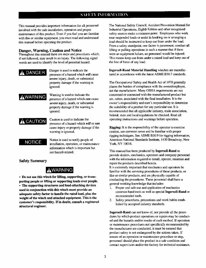
Danger, Warning, Caution and Notice Throughout this manual there are steps and procedures which, if not followed, may result in an injury. The following signal words are used to identify the level of potential hazard.
Safety Summary
Danger is used to indicate the
presence of a hazard which will cause severe injury, death, or substantial property damage if the warning is
ignored.
Warning is used to indicate the
presence of a hazard which can cause
severe injury, death, or substantial property damage if the warning is
ignored.
Caution is used to indicate the
presence of a hazard which will or can cause injury or property damage if the warning is ignored.
Notice is used to notify people of installation, operation, or maintenance information which is important but
not hazard-related.
l Do not use this winch for lifting, supporting, or trans- porting people or lifting or supporting loads over people. l The supporting structures and load-attaching devices used in conjunction with this winch must provide an adequate safety factor to handle the rated load, plus the weight of the winch and attached equipment. This is the customer’s responsibility. If in doubt, consult a registered structural engineer.
The National Safety Council, Accident Prevention Manual for Industrial Operations, Eighth Edition and other recognized
safety sources make a common point: Employees who work near suspended loads or assist in hooking on or arranging a load should be instructed to keep out from under the load. From a safety standpoint, one factor is paramount: conduct all lifting or pulling operations in such a manner that if there
were an equipment failure, no personnel would be injured. This means keep out from under a raised load and keep out of
the line of force of any load.
Ingersoll-Rand Material Handling winches are manufac- tured in accordance with the latest ASME B30.7 standards.
The Occupational Safety and Health Act of 1970 generally places the burden of compliance with the owner/employer, not the manufacturer. Many OSHA requirements are not
concerned or connected with the manufactured product but
are, rather, associated with the final installation. It is the owner’s responsibility and user’s responsibility to determine the suitability of a product for any particular use. It is
recommended that all applicable industry, trade association, federal, state and local regulations be checked. Read all operating instructions and warnings before operation.
Rigging: It is the responsibility of the operator to exercise caution, use common sense and be familiar with proper rigging techniques. See ASME B30.9 for rigging information,
American National Standards Institute, 1430 Broadway, New York, NY 10018.
This manual has been produced by Ingersoll-Rand to
provide dealers, mechanics, operators and company personnel with the information required to install, operate, maintain and repair the products described herein.
It is extremely important that mechanics and operators be familiar with the servicing procedures of these products, or
like or similar products, and are physically capable of conducting the procedures. These personnel shall have a general working knowledge that includes:
1. Proper and safe use and application of mechanics common hand tools as well as special Ingersoll-Rand or recommended tools.
2. Safety procedures, precautions and work habits estab- lished by accepted industry standards.
Ingersoll-Rand can not know of, nor provide all the proce-
dures by which product operations or repairs may be conduct- ed and the hazards and/or results of each method. If operation or maintenance procedures not specifically recommended by the manufacturer are conducted, it must be ensured that product safety is not endangered by the actions taken. If
unsure of an operation or maintenance procedure or step, personnel should place the product in a safe condition and
contact supervisors and/or the factory for technical assistance.
3
The following warnings and operating instructions have been adapted in part from American National (Safety) Standard ASME B30.7 and arc intended to avoid unsafe operating
practices which might lead to injury or property damage.
Ingersoll-Rand recognizes that most companies who use winches have a safety program in force at their facility. In the event that some conflict exists between a rule set forth in this publication and a similar rule already set by an individual company, the more stringent of the two should take prece-
dence.
Safe Operating Instructions are provided to make an operator
aware of dangerous practices to avoid and are not necessarily limited to the following list. Refer to specific sections in the
manual for additional safety information.
1. Only allow personnel trained in safety and operation of this winch to operate and maintain this product.
2. Only operate a winch if you are physically fit to do so. 3. When a “DO NOT OPERATE” sign is placed on the winch,
or controls, do not operate the winch until the sign has been removed by designated personnel.
4. Before each shift, check the winch for wear and damage. Never use a winch that inspection indicates is worn or
damaged.
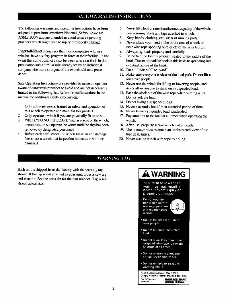
Each unit is shipped from the factory with the warning tag
shown. If the tag is not attached to your unit, order a new tag
and install it. See the parts list for the part number. Tag is not shown actual size.
5. Never lift a load greater than the rated capacity of the winch.
See warning labels and tags attached to winch. 6. Keep hands, clothing, etc., clear of moving parts. 7. Never place your hand in the throat area of a hook or
near wire rope spooling onto or off of the winch drum. 8. Always rig loads properly and carefully. 9. Be certain the load is properly seated in the saddle of the
hook. Do not tipload the hook as this leads to spreading and eventual failure of the hook.
10. Do not “side pull” or “yard’. 11. Make sure everyone is clear of the load path. Do not lift a
load over people. 12. Never use the winch for lifting or lowering people, and
never allow anyone to stand on a suspended load. 13. Ease the slack out of the wire rope when starting a lift.
Do not jerk the load. 14. Do not swing a suspended load.
15. Never suspend a load for an extended period of time. 16. Never leave a suspended load unattended. 17. Pay attention to the load at all times when operating the
winch. 18. After use, properly secure winch and all loads.
19. The operator must maintain an unobstructed view of the
load at all times. 20. Never use the winch wire rope as a sling.
I
4

Model Code
Example: FA2-16MK320P FA2 - 16 M
Series (Capacity):
Model FA2 (2 metric tons / 4400 lbs)
Model FA2.5 (2.5 US TONS / 5000 lbs)
Drum Flange Height or Man Rider Designation:
= 19 inch (483 mm) diameter (Standard).
MR = Man Rider@ *
Drum Length (Distance between drum flanges):
8 = 8 inch (203 mm)
12 = 12 inch (305 mm)
16 = 16 inch (406 mm)
24 = 24 inch (610 mm) [Standard]
Drum Brake:
A = Automatic Drum Brake
M = Manual Drum Brake -I
K 320 P
X = None
Disc Brake:
K = Automatic Disc Brake
X = None
Control:
1 = Winch mounted lever throttle (Standard)
2xx = Remote full flow lever throttle (XX = Specify hose length (feet). Max 20 ft. (6 metres)) **
3xx = Remote pilot pendant throttle (XX = Specify hose length (feet). Max 50 ft. (15 metres) **
4xx = Remote pilot lever throttle. (XX = Specify hose length (feet). Max 50 ft. (15 metres)) **
Options: ***
Z = Sand blast and Carbozinc primer only
P = Marine 812 top coat
G = Drum Guard
7 = Drum Grooving (Number = wire rope size in sixteenths, e.g. 7/16 inch)
D = Drum Divider Flange and additional wire rope anchor
T = Tensioning Manifold
S = Rotary Limit Switch ****
L = Drum Locking Pin
* Reference Man Rider@ Manual Supplement, Form No. MHD56046.
** Remote throttles are provided with 10 feet (3 metres) of hose. Specify hose lengths greater than 10 feet. For lengths greater than 20 ft. (6 metres) with the Remote Full Flow Throttle, or 50 ft. (15 metres) with the Remote Pilot Lever and Remote Pilot Pendant Throttles contact Technical Sales for control acceptability. Metric lengths for reference only, order lengths required to be in feet.
*** Documentation, witness testing and material traceability available. Specify options or contact the factory or your nearest Ingersoll-Rand distributor for information.
**** Includes mandatory remote full flow lever or remote pilot pendant throttle with 10 feet (3 metres) of hose. Contact technical sales for application suitability.
5

General Specifications
Rated Operating Pressure
FA2
Model
FA2.5
90 psig (6.2 bar) Air System Consumption Volume
(at rated pressure) 335 scfm 10 cu.m/min 700 scfm 20 cu.m/min Full Drum Line Pull 4,400 lbs 2,000 kgs 5,000 lbs 2,268 kgs
Mid Drum Line Speed 55 fpm 17 m/min 145 fpm 44 m/min Rated Performance
(at rated pressure / volume) Max Stall Pull - 1st Layer 9,000 lbs 4,082 kgs 10,000 lbs 4,536 kgs
FA2-24MX1 Net Weight 720 lbs 327 kgs --- ---
FA2.5-24MX1 Net Weight --- --- 910 lbs 413 kgs
Air Motor Pipe Inlet Size 1 inch 25 mm 1-1/4 inch 32 mm Minimum Air System Hose Size 1-1/4 inch 32 mm 1-1/2 inch 38 mm
Wire Rope Diameter
Drum Wire Rope Storage Capacity *
(feet / metres)
Performance Graphs
FA2 Winch FA2.5 Winch
Drum Length (inches) 1/2 Inch ** 13 mm ** 5/8 inch 16 mm
8 454 ft 138 m 171 ft 52 m
12 681 ft 207 m 256 ft 78 m 16 908 ft 277 m 338 ft 103 m 24 1,362 ft 415 m 512 ft 156 m
* Wire rope storage is based on a FA2 or FA2.5 Winch with a 19 inch (483 mm) diameter drum flange and on ASME
standards which require the top layer to be at least 112 inch (13 mm) below the drum flange diameter.
Capacities shown may vary from those published elsewhere.
** Capacities apply to FA2 winch only.
6
Prior to installing the winch, carefully inspect it for possible
shipping damage. Winches are supplied fully lubricated from the factory. Before operation check oil levels and adjust as necessary. Use the proper type of oil as recommended in the “LUBRICATION” section.
l Owners and users are advised to examine specific, local or other regulations, including American National Standards Institute and/or OSHA Regulations which may apply to a particular type of use of this product before installing or putting winch to use.
Mounting Care must be taken when moving, positioning or mounting the
winch. In most cases, lifting lugs have been provided to assist in handling the winch. If the lug locations are improper for
your specific installation, great care should be taken to ensure that the winch, when lifted, will be properly balanced.
Determine the weight of your winch by refering to the “SPECIFICATIONS” section. Lift the winch 3 to 4 inch (75
to 100 mm) off the ground. Verify winch is balanced and
secure before continuing lift. Mount the winch so the axis of the drum is horizontal and that
the motor vent cap is not more than 15° off top vertical center.
If the winch is to be mounted in an inverted position, the
motor case must be rotated to position the vent cap at the top. 1. The winch mounting surface must be flat and of sufficient
strength to handle the rated load plus the weight of the
winch and attached equipment. An inadequate foundation may cause distortion or twisting of the winch uprights and side rails resulting in winch damage.
2. Make sure the mounting surface is flat to within l/16 inch (2.0 mm). Shim if necessary.
3. Mounting bolts must be 5/8 inch ( 16 mm) Grade 8 or better. Use self-locking nuts or nuts with lockwashers.
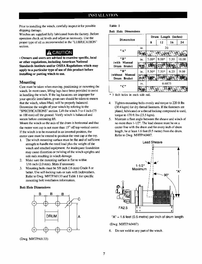
Refer to Dwg. MHTPA0133 and Table 1 for specific mounting bolt installation information.
Bolt Hole Dimensions
Table 1
Bolt Hole Dimensions
Dimension
with Manual
without Manual
* 3 Bolt holes in each side rail.
4. Tighten mounting bolts evenly and torque to 220 ft lbs (30.4 kgm) for dry thread fasteners. If the fasteners are
plated, lubricated or a thread locking compound is used,
torque to 170 ft lbs (23.5 kgm). 5. Maintain a fleet angle between the sheave and winch of
no more than 1 -l/2”. The lead sheave must be on a center line with the drum and for every inch of drum length, be at least 1.6 feet (0.5 metre) from the drum.
Refer to Dwg. MHTPA0487.
Lead Sheave n
“A” = 1.6 feet (0.5 metre) per inch of drum length
(Dwg. MHTPA0487)
6. Do not weld to any part of the winch.
(Dwg. MHTPA0133)
7

Wire Rope
l Maintain at least 3 tight wraps of wire rope on the drum at all times. l Install the wire rope to come off the drum for overwind operation. Refer to Dwg. MHTPA0202.
Wire rope take off for
overwind operation (viewed from motor end)
(Dwg. MHTPA0202)
l Some applications may require underwind operation. Consult the factory prior to use.
Wire Rope Selection Consult a reputable wire rope manufacturer or distributor for
assistance in selecting the appropriate type and size of wire rope and, where necessary, a protective coating. Use a wire rope which provides an adequate safety factor to handle the
actual working load and that meets all applicable industry, trade association, federal, state and local regulations. When considering wire rope requirements the actual working load must include not only the static or dead load but also loads resulting from acceleration, retardation
and shock load. Consideration must also be given to the size of the winch wire rope drum, sheaves and method of reeving. Wire rope construction must be 6 X 19 or 6 X 37 IWRC right lay to permit correct installation of wire rope anchor. Refer to Table 2 for minimum and maximum recommended wire rope
diameters.
Table 2
I Minimum and Maximum Wire Rope Size I
8
Installing Wire Rope (Refer to Dwg. MHTPA0166.) 1. Cut wire rope to length in accordance with the wire rope
manufacturer’s instructions.
2. Feed the end of the wire rope into the cable anchor hole in the drum and pull through approximately one foot (305 mm) of wire rope.
Wire
(Dwg. MHTPA0166)
3.
4.
5.
6.
7.
Wrap the wire rope with wire a distance from the end
equal to the wedge length plus one inch (25 mm). Slide the sleeve over the end of the wire rope so the larger diameter of the taper bore is nearest the end of the wire rope.
Spread the end strands of the wire rope and insert the split wedge until it is below the end of the wire rope.
Pull the sleeve over the wire rope end until tight. Check that the wire rope strands stay in the slots located on the split wedge. Pull the wire rope anchor into position in the drum
anchor pocket.
l Make sure the first wrap of wire rope is tight and lays flush against the drum flange.
Safe Wire Rope Handling Procedures 1. Always use gloves when handling wire rope.
2. Never use wire rope which is frayed or kinked.
3. Never use wire rope as a sling.
4. Always ensure wire rope is correctly spooled and the
first layer is tight against the drum.
Wire Rope Spooling To compensate for uneven spooling and the decrease in line
pull capacity as the drum fills up, use as short a wire rope as practical. When rewinding apply tension to the end of the
wire rope to eliminate line slack. This helps achieve level winding and tight spooling.
Rigging Make sure all wire rope blocks, tackle and fasteners have a sufficient safety margin to handle the required load under all
conditions. Do not allow wire rope to contact sharp edges or make sharp bends which will cause damage to wire rope, use a sheave. Refer to the wire rope manufacturer’s handbook for
proper sizing, use and care of wire rope.
Safe Installation Procedures 1. Do not use wire rope as a ground (earth) for welding. 2. Do not attach a welding electrode to winch or wire rope. 3. Never run the wire rope over a sharp edge. Use a
correctly sized sheave. 4. When a lead sheave is used, it must be aligned with the
center of the drum. The diameter of the lead sheave must be at least 18 times the diameter of the wire rope. Refer to Dwg. MHTPA0487.
5. Always maintain at least three full, tight wraps of wire rope on the drum.
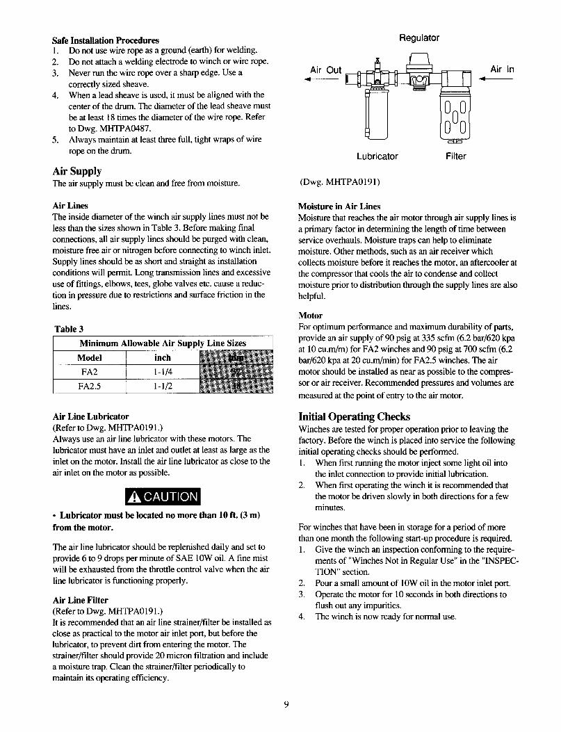
Air Supply The air supply must be clean and free from moisture. (Dwg. MHTPA0191)
Air Lines The inside diameter of the winch air supply lines must not be
less than the sizes shown in Table 3. Before making final connections, all air supply lines should be purged with clean, moisture free air or nitrogen before connecting to winch inlet. Supply lines should be as short and straight as installation conditions will permit. Long transmission lines and excessive
use of fittings, elbows, tees, globe valves etc. cause a reduc- tion in pressure due to restrictions and surface friction in the
lines.
Air Line Lubricator (Refer to Dwg. MHTPA0191.) Always use an air line lubricator with these motors. The lubricator must have an inlet and outlet at least as large as the
inlet on the motor. Install the air line lubricator as close to the
air inlet on the motor as possible.
l Lubricator must be located no more than 10 ft. (3 m) from the motor.
The air line lubricator should be replenished daily and set to
provide 6 to 9 drops per minute of SAE 10W oil. A fine mist will be exhausted from the throttle control valve when the air
line lubricator is functioning properly.
Air Line Filter (Refer to Dwg. MHTPA0191.) It is recommended that an air line strainer/filter be installed as close as practical to the motor air inlet port, but before the lubricator, to prevent dirt from entering the motor. The strainer/filter should provide 20 micron filtration and include a moisture trap. Clean the strainer/filter periodically to maintain its operating efficiency.
Regulator
Air Out 4
Air In
Lubricator Filter
Moisture in Air Lines Moisture that reaches the air motor through air supply lines is a primary factor in determining the length of time between
service overhauls. Moisture traps can help to eliminate moisture. Other methods, such as an air receiver which collects moisture before it reaches the motor, an aftercooler at
the compressor that cools the air to condense and collect moisture prior to distribution through the supply lines are also
helpful.
Motor For optimum performance and maximum durability of parts,
provide an air supply of 90 psig at 335 scfm (6.2 bar/620 kpa at 10 cum/m) for FA2 winches and 90 psig at 700 scfm (6.2
bar/620 kpa at 20 cu.m/min) for FA2.5 winches. The air motor should be installed as near as possible to the compres- sor or air receiver. Recommended pressures and volumes are
measured at the point of entry to the air motor.
Initial Operating Checks Winches are tested for proper operation prior to leaving the factory. Before the winch is placed into service the following
initial operating checks should be performed.
1. When first running the motor inject some light oil into the inlet connection to provide initial lubrication.
2. When first operating the winch it is recommended that
the motor be driven slowly in both directions for a few minutes.
For winches that have been in storage for a period of more
than one month the following start-up procedure is required. 1. Give the winch an inspection conforming to the require-
ments of “Winches Not in Regular Use” in the “INSPEC-
TION” section.
2. Pour a small amount of 10W oil in the motor inlet port. 3. Operate the motor for 10 seconds in both directions to
flush out any impurities. 4. The winch is now ready for normal use.
The four most important aspects of winch operation are: 1. Follow all safety instructions when operating the winch. 2. Allow only people trained in safety and operation of this
winch to operate this equipment.
3. Subject each winch to a regular inspection and mainte- nance procedure.
4. Be aware of the winch capacity and weight of load at all times.
l Only allow personnel instructed in safety and operation to operate a winch. l To avoid damage to the rigging, the structure supporting the rigging and the winch, do not “two-block” the end of the wire rope.
l The winch is not designed or suitable for lifting, lowering or moving persons. Never lift loads over people.
Winch Controls The spring loaded, motor mounted, manual throttle control valve is standard to, and normally supplied with, this winch. Optional motor throttle controls are available. Reference the model code on the winch nameplate and compare it to the
“SPECIFICATIONS” section of this manual to determine your configuration. The throttle controls provide operator control of the motor speed and direction of drum rotation.
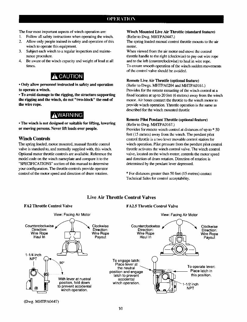
FA2 Throttle Control Valve
Live Air Throttle Control Valves
FA2.5 Throttle Control Valve
View: Facing Air Motor View: Facing Air Motor
Winch Mounted Live Air Throttle (standard feature) (Refer to Dwg. MHTPA0447.) The spring loaded manual control throttle mounts to the air motor. When viewed from the air motor end move the control throttle handle to the right (clockwise) to pay out wire rope and to the left (counterclockwise) to haul in wire rope. To ensure smooth operation of the winch sudden movements of the control valve should he avoided.
Remote Live Air Throttle (optional feature) (Refer to Dwgs. MHTPA0204 and MHTPA0161.) Provides for the remote mounting of the winch control at a fixed location at up to 20 feet (6 metres) away from the winch
motor. Air hoses connect the throttle to the winch motor to provide winch operation. Throttle operation is the same as described for the winch mounted throttle
Remote Pilot Pendant Throttle (optional feature) (Refer to Dwg. MHTPA0167.) Provides for remote winch control at distances of up to * 50 feet (15 metres) away from the winch. The pendant pilot control throttle is a two lever movable control station for winch operation. Pilot pressure from the pendant pilot control
throttle activates the winch control valve. The winch control
valve, located on the winch motor, controls the motor speed and direction of drum rotation. Direction of rotation is determined by the pendant lever depressed.
* For distances greater than 50 feet (15 metres) contact Technical Sales for control acceptability.
Clockwise Direction:
Wire Rope Payout
With lever at nuetral position, fold down
to prevent accidental winch operation.
Counterclockwise Direction:
Clockwise Direction:
Wire Rope Payout
- Place latch in this position.
(Dwg. MHTPA0447)
10
Remote Pilot Lever Throttle (optional feature) Provides for remote winch control at distances of up to * 50
feet (15 metres) away from the winch. The lever pilot control throttle is a fixed mount lever control station for winch
operation. pilot pressure from the lever pilot control throttle activates the winch control valve. The winch control valve, located on the winch motor, controls the motor speed and direction of drum rotation. Direction of rotation is determined by the direction in which the lever is shifted.
* For distances greater than 50 feet ( 15 metres) contact Technical Sales for control acceptability.
Winch Brakes (Refer to Dwgs. MHTPB0152 and MHTPB0209.) Manual Drum Brake The manual drum brake may be applied by pushing down on
the handle (104) and released by pulling up. If the handle is pushed down fully, it should lock in that position and prevent
drum rotation, until released by the operator. The brake must be kept properly adjusted to hold the required load.
Automatic Drum Brake (optional feature) The automatic drum brake is a spring applied, air released brake. Using an air actuated, spring loaded cylinder (110), the
brake automatically disengages when the motor is operated. Air pressure in the cylinder overcomes spring pressure to
release the brake. When the control valve is placed in the neutral position, the air in the cylinder (110) is vented and the
spring automatically engages the brake to prevent drum rotation. The cylinder clevis (107) must be kept properly adjusted to
hold the required load.
Automatic Disc Brake (optional feature) The automatic disc brake is a spring applied, air released
brake. Using an air actuated, spring loaded piston (lo), the brake automatically disengages when the motor is operated.
Air pressure ported through the brake housing (2 1) shifts the piston (10) which overcomes spring pressure, disengages the friction discs ( 16) and releases the brake. When the control
valve is placed in the neutral position, the air is vented and the springs (9) shift the piston to engage the brake and prevent
drum rotation.
Drum Locking Pin (optional feature) (Refer to Dwg. MHTPB0155.) The drum locking pin is mounted to the winch on the end
opposite the motor. It should be engaged by inserting the lock pin (136) into one of the holes in the drum (80) flange anytime a load is left suspended. The drum lock is operated by rotating a pin between two slots, one shallow the other
deep. To engage the locking pin rotate the drum (80) flange so that one of the 12 holes aligns with the locking pin ( 136). Pull out pull rod (140) and rotate counterclockwise 90°, aligning the pin ( 135) with the deep groove on gland ( 138). Release pull
rod and ensure locking pin engages and is seated in the drum hole and gland ( 138) deep groove.
l Ensure that all braking mechanisms are engaged and all personnel are clear of the winch load and rigging before disengaging the locking pin. l Extremely difficult locking pin release is an indication that the load is held by the locking pin and the braking mechanisms are not functioning properly. Do not release the locking pin until load control is established.
To disengage the locking pin pull the pull rod (140) out until the pin ( 135) is clear of the deep groove and rotate clockwise
90°. Align pin with the shallow groove on gland (138) and release pull rod. Ensure pin is seated in the gland shallow
groove.
11

To ensure continued satisfactory operation of the winch, all points requiring lubrication must be serviced with the correct lubricant at the proper time interval as indicated for each assembly.
The lubrication intervals recommended in this manual are based on intermittent operation of the winch eight hours each day, five days per week. If the winch is operated almost continuously or more than the eight hours each day, more frequent lubrication will be required. Also, the lubricant types and change intervals are based on operation in an environ- ment relatively free of dust, moisture, and corrosive fumes. Use only those lubricants recommended. Other lubricants may affect the performance of the winch. Approval for the use of other lubricants must be obtained from your
Ingersoll-Rand distributor. Failure to observe this precau- tion may result in damage to the winch and/or its associated components.
INTERVAL
Start of each shift.
LUBRICATION CHECKS
Check flow and level of air line lubricator (approximately 10 to 1.5 drops per minute required at
maximum motor speed).
Check oil level in the motor.
Monthly Lubricate components supplied by
Check oil level in the reduction
Yearly
gear assembly.
Drain and refill the oil in the winch reduction gear assembly.
Drain and refill the oil in the winch motor.
Recommended Lubricants Oil
Temperature Type Oil 1. Below 32° F (0° C) SAE 10W
2. 32° to 80° F (0° to 27° C) SAE 20W 3. Above 80° F (27° C) SAE 30W
Grease Temperature
1. -20° to 50° F (-30° to 10° C)
2. 30° to 120° F
(-1° to49° C)
Type Grease EP 1 multipurpose lithium-based grease EP 2 multipurpose lithium-based grease
Motor Lubrication Locations (FA2 Shown)
Level Plug
Drain Plug
(Dwg. MHTPA0222)
Motor (Refer to Dwg. MHTPA0222.) Correct lubrication is one of the most important factors in maintaining efficient winch operation. The motor is splash lubricated by the oil in the motor housing and has no other
means of lubrication. It is therefore important to use only quality, non-detergent motor oil to ensure maximum perfor- mance and minimum downtime for repairs. Refer to the
‘Recommeded Lubricants’ section. Allow oil to settle before topping off. Oil capacity for the FA2 winch motor is 3/8 quart (0.35
litres). Add oil through the fill plug opening until oil flows from the level plug hole. Add oil slowly to prevent spilling.
Oil capacity for the FA2.5 winch K5B-546 motor is 3 quarts (2.8 litres.). Add oil through the tiller opening until oil flows from the level plug hole. Baffles are installed in the FA2.5 motor at each motor fill port. Add oil slowly to prevent spilling. The motor should be level-checked daily or at the start of
each shift after accumulated water has been drained off. When motors are operated in temperatures below freezing, wait long enough at end of shift for water to separate from oil
but not long enough for it to freeze. Drain the water then refill to the level plug. If desired, all the oil may be drained at the end of the shift and the motor refilled with new oil.
Wire Rope Follow the wire rope manufacturer’s instructions. At a
minimum, observe the following guidelines. 1. Clean with a brush or steam to remove dirt, rock dust or
other foreign material on the surface of the wire rope.
12
l Do not use an acid-based solvent. Only use cleaning fluids and lubricants specified by the wire rope manufac- turer.
2. Apply a wire rope lubricant, LUBRI-Link® or SAE 30W oil.
3. Brush, drip or spray lubricant weekly, or more frequent- ly, depending on severity of service.
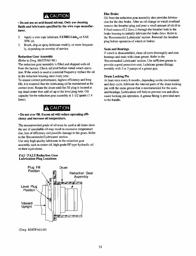
Reduction Gear Assembly (Refer to Dwg. MHTPA0140.)
The reduction gear assembly is filled and shipped with oil from the factory. Check oil level before initial winch opera- tion. If the winch is used at a normal frequency replace the oil
in the reduction housing once every year. To ensure correct performance, highest efficiency and long life, it is essential that the lubricating oil be maintained at the correct level. Rotate the drum until the fill plug is located at
top dead center then add oil up to the level plug hole. Oil capacity for the reduction gear assembly is 1-l/2 quarts ( 1.4 litres).
l Do not over fill. Excess oil will reduce operating effi- ciency and increase oil temperature.
The recommended grade of oil must be used at all times since
the use of unsuitable oil may result in excessive temperature rise, loss of efficiency and possible damage to the gears. Refer to the ‘Recommeded Lubricants’ section. Use only high quality lubricants in the reduction gear assembly such as motor oil, high grade EP type hydraulic oil
or their equivalents.
FA2 / FA2.5 Reduction Gear Lubrication Plug Locations
Plug Fill Position
\
(Dwg. MHTPA0140)
Drum
Disc Brake Oil from the reduction gear assembly also provides lubrica-
tion for the disc brake. After an oil change or winch overhaul
remove the breather plug and pour a small amount of oil (6 to 8 fluid ounces (0.2 litres.)) through the breather hole in the
brake housing to initially lubricate the brake discs. Refer to the ‘Recommeded Lubricants’ section. Reinstall the breather plug before operation of winch or brakes.
Seals and Bearings If winch is disassembled, clean all parts thoroughly and coat bearings and seals with clean grease. Refer to the
‘Recommeded Lubricants’ section. Use sufficient grease to
provide a good protective coat. Lubricate grease fittings monthly with 2 or 3 pumps of a grease gun.
Drum Locking Pin At least once every 6 months, depending on the environment
and duty cycle, lubricate the internal parts of the drum locking pin with the same grease that is recommended for the seals
and bearings. Lubrication will help to prevent rust and allow easier locking pin operation. A grease fitting is provided next
to the handle.
13
Inspection information is based in part on American National
Standards Institute Safety Codes (ASME B30.7).
l All new, altered or modified equipment should be inspected and tested by personnel instructed in safety, operation and maintenance of this equipment to ensure safe operation at rated specifications before placing equipment in service. l Never use a winch that inspection indicates is defective.
Frequent and periodic inspections should be performed on equipment in regular service. Frequent inspections are visual examinations performed by operators or personnel trained in
safety and operation of this equipment and include observa- tions made during routine equipment operation. Periodic inspections are thorough inspections conducted by personnel
trained in the safety, operation and maintenance of this equipment. ASME B30.7 states inspection intervals depend upon the nature of the critical components of the equipment
and the severity of usage. Frequent and periodic inspection intervals for equipment use under various operating condi-
tions are listed below:
1. Frequent Inspection:
NORMAL HEAVY SEVERE monthly weekly daily
2. Periodic Inspection:
NORMAL HEAVY SEVERE yearly yearly quarterly
Careful inspection on a regular basis will reveal potentially dangerous conditions while still in the early stages, allowing corrective action to be taken before the condition becomes
dangerous.
Deficiencies revealed through inspection, or noted during operation, must be reported to designated personnel instructed in safety, operation and maintenance of this equipment. A determination as to whether a condition constitutes a safety hazard must be decided, and the correction of noted safety
hazards accomplished and documented by written report before placing the equipment in service.
Records and Reports Inspection records, listing all points requiring periodic inspection should be maintained for all load bearing equip- ment. Written reports, based on severity of service, should be
made on the condition of critical parts as a method of documenting periodic inspections. These reports should be dated, signed by the person who performed the inspection, and kept on file where they are readily available for review.
Wire Rope Reports Records should be maintained as part of a long-range wire rope inspection program. Records should include the condi- tion of wire rope removed from service. Accurate records will establish a relationship between visual observations noted during frequent inspections and the actual condition of wire rope as determined by periodic inspections.
Frequent Inspection On equipment in continuous service, frequent inspection should be made by operators at the beginning of each shift. In addition, visual inspections should be conducted during regular operation for damage or evidence of malfunction.
WINCH. Prior to operation, visually inspect winch housings, controls, brakes, sideplates and drum for indications of damage. Do not operate the winch unless
the wire rope feeds onto the drum smoothly, and any discrepancies noted have been reviewed and inspected further by personnel instructed in the operation, safety and maintenance of this winch.
WIRE ROPE. Visually inspect all wire rope which can be expected to be in use during the day’s operations.
Inspect for damage indicated by distortion of wire rope such as kinking, “birdcaging,” core protrusion, main
strand displacement, corrosion, broken or cut strands. Also inspect the drum flange points, crossover points and repetitive pickup points. If damage is evident, do not
operate winch until the discrepancies have been reviewed and inspected further by personnel instructed in the
operation, safety and maintenance of this winch.
l The full extent of wire rope wear cannot be determined by visual inspection. At any indication of wear inspect the wire rope in accordance with instructions in “Periodic Inspection.”
3. AIR SYSTEM. Visually inspect all connections, fittings,
hoses and components for indication of air leaks. Repair any leaks or damaged components found.
4. CONTROLS. During operation of winch, verify
response to control is quick and smooth. If winch responds slowly or movement is unsatisfactory, do not operate winch until all defects have been corrected.
5. BRAKES. During winch operation test brakes.
14
Periodic Inspection Disassembly may be required as a result of frequent inspec-
tion findings or in order to properly inspect the individual components. Disassembly steps are described in the “MAIN- TENANCE” section. Maintain written records of periodic inspections to provide an accumulative basis for continuing evaluation. Inspect all items listed in “Frequent Inspection.” Also inspect the following: 1. SIDE FRAMES. Check for deformed, cracked or
corroded main components. Replace damaged parts.
2. FASTENERS. Check retainer rings, split pins, cap- screws, nuts, and other fasteners on winch, including
mounting bolts. Replace if missing or damaged and tighten if loose.
3. DRUM AND SHEAVES. Check for cracks, wear or damage. Replace if necessary.
4. WIRE ROPE. Additionally inspect for the following:
a. Build-up of dirt and corrosion. Clean with steam or a stiff wire brush to remove dirt and corrosion if
necessary. b. Loose or damaged end connection. Replace if
loose or damaged.
C. Check wire rope anchor is secure in drum.
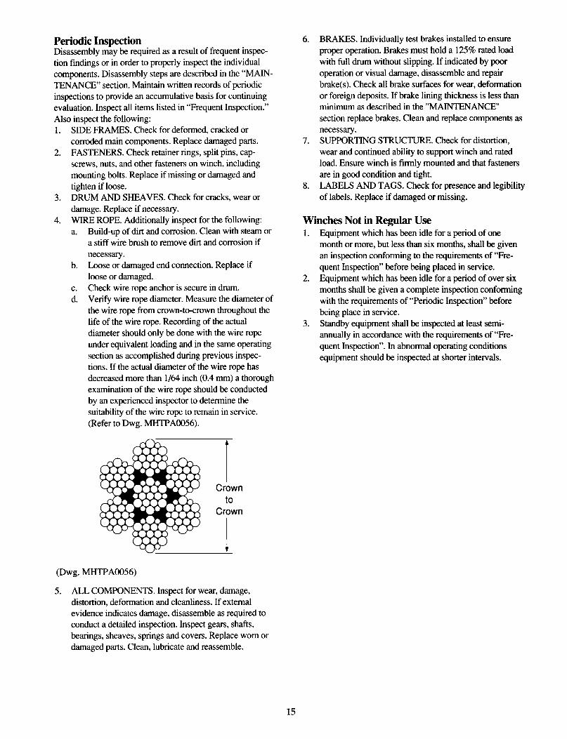
d. Verify wire rope diameter. Measure the diameter of the wire rope from crown-to-crown throughout the
life of the wire rope. Recording of the actual diameter should only be done with the wire rope under equivalent loading and in the same operating
section as accomplished during previous inspec- tions. If the actual diameter of the wire rope has
decreased more than l/64 inch (0.4 mm) a thorough examination of the wire rope should be conducted by an experienced inspector to determine the
suitability of the wire rope to remain in service. (Refer to Dwg. MHTPA0056).
(Dwg. MHTPA0056)
5. ALL COMPONENTS. Inspect for wear, damage, distortion, deformation and cleanliness. If external evidence indicates damage, disassemble as required to conduct a detailed inspection. Inspect gears, shafts, bearings, sheaves, springs and covers. Replace worn or damaged parts. Clean, lubricate and reassemble.
6. BRAKES. Individually test brakes installed to ensure
proper operation. Brakes must hold a 125% rated load with full drum without slipping. If indicated by poor
operation or visual damage, disassemble and repair
brake(s). Check all brake surfaces for wear, deformation or foreign deposits. If brake lining thickness is less than minimum as described in the “MAINTENANCE”
section replace brakes. Clean and replace components as
necessary. 7. SUPPORTING STRUCTURE. Check for distortion,
wear and continued ability to support winch and rated load. Ensure winch is firmly mounted and that fasteners
are in good condition and tight. 8. LABELS AND TAGS. Check for presence and legibility
of labels. Replace if damaged or missing.
Winches Not in Regular Use 1. Equipment which has been idle for a period of one
month or more, but less than six months, shall be given an inspection conforming to the requirements of “Fre-
quent Inspection” before being placed in service.
2. Equipment which has been idle for a period of over six months shall be given a complete inspection conforming with the requirements of “Periodic Inspection” before
being place in service.
3. Standby equipment shall be inspected at least semi- annually in accordance with the requirements of “Fre- quent Inspection”. In abnormal operating conditions
equipment should be inspected at shorter intervals.
15
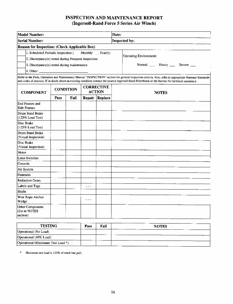
INSPECTION AND MAINTENANCE REPORT (Ingersoll-Rand Force 5 Series Air Winch)
(Model Number: Date:
Serial Number:
Reason for Inspection: (Check Applicable Box)
Inspected by:
1. Scheduled Periodic Inspection ( _ Monthly _ Yearly)
2. Discrepancy(s) noted during Frequent Inspection
3. Discrepancy(s) noted during maintenance
4. Other:
Operating Environment:
Normal _ Heavy _ Severe _
COMPONENT NOTES
( 125% Load Test)
Controls
Air System
TESTING Pass Fail NOTES
Operational (No Load)
Operational ( 10% Load)
Operational (Maximum Test Load *)
* Maximum test load is 125% of rated line pull.
16
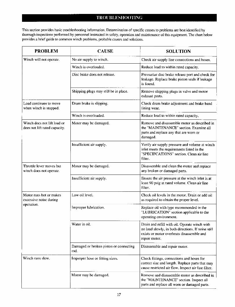
This section provides basic troubleshooting information. Determination of specific causes to problems are best identified by thorough inspections performed by personnel instructed in safety, operation and maintenance of this equipment. The chart below provides a brief guide to common winch problems, probable causes and solutions.
PROBLEM CAUSE SOLUTION
Winch will not operate. No air supply to winch. Check air supply line connections and hoses.
Winch is overloaded. Reduce load to within rated capacity.
Disc brake does not release. Pressurize disc brake release port and check for leakage. Replace brake piston seals if leakage
is found.
Shipping plugs may still be in place. Remove shipping plugs in valve and motor
exhaust ports.
Load continues to move Drum brake is slipping. Check drum brake adjustment and brake band
when winch is stopped. lining wear.
Winch is overloaded. Reduce load to within rated capacity.
Winch does not lift load or Motor may be damaged. Remove and disassemble motor as described in
does not lift rated capacity. the “MAINTENANCE” section. Examine all
parts and replace any that are worn or damaged.
Insufficient air supply. Verify air supply pressure and volume at winch inlet meets the requirements listed in the
“SPECIFCATIONS” section. Clean air line
filter.
Throttle lever moves but Motor may be damaged. Disassemble and clean the motor and replace
winch does not operate. any broken or damaged parts.
Insufficient air supply. Ensure the air pressure at the winch inlet is at least 90 psig at rated volume. Clean air line filter.
Motor runs hot or makes Low oil level. Check oil levels in the motor. Drain or add oil
excessive noise during as required to obtain the proper level.
operation. Improper lubrication. Replace oil with type recommended in the
“LUBRICATION” section applicable to the
operating environment.
Water in oil. Drain and refill with oil. Operate winch with no load slowly, in both directions. If noise still
exists or motor overheats disassemble and repair motor.
Damaged or broken piston or connecting Disassemble and repair motor.
rod.
Winch runs slow. Improper hose or fitting sizes. Check fittings, connections and hoses for correct size and length. Replace parts that may
cause restricted air flow. Inspect air line filter.
Motor may be damaged. Remove and disassemble motor as described in the “MAINTENANCE” section. Inspect all
parts and replace all worn or damaged parts.
17
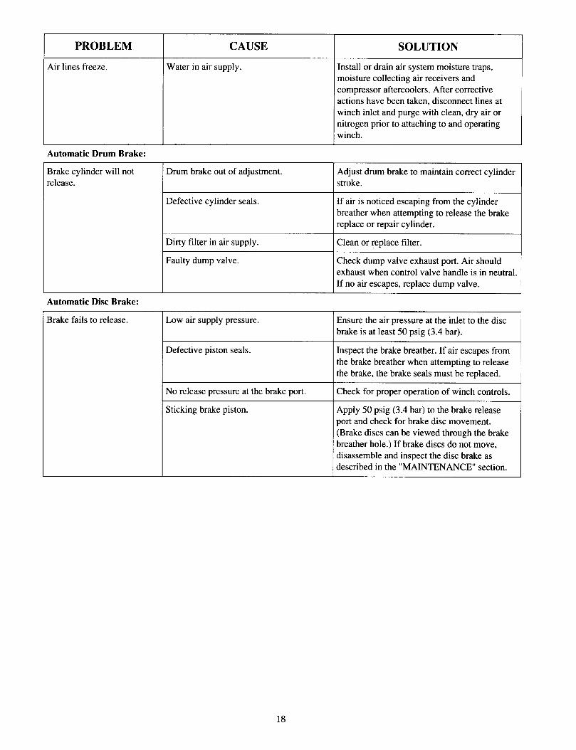
PROBLEM CAUSE
Air lines freeze. Water in air supply.
Automatic Drum Brake:
Brake cylinder will not release.
SOLUTION
Install or drain air system moisture traps, moisture collecting air receivers and compressor aftercoolers. After corrective actions have been taken, disconnect lines at winch inlet and purge with clean, dry air or nitrogen prior to attaching to and operating winch.
Drum brake out of adjustment. Adjust drum brake to maintain correct cylinder stroke.
Defective cylinder seals. If air is noticed escaping from the cylinder
breather when attempting to release the brake replace or repair cylinder.
Dirty filter in air supply.
Faulty dump valve.
Clean or replace filter.
Check dump valve exhaust port. Air should
exhaust when control valve handle is in neutral.
If no air escapes, replace dump valve.
Automatic Disc Brake:
Brake fails to release. Low air supply pressure. Ensure the air pressure at the inlet to the disc
brake is at least 50 psig (3.4 bar).
Defective piston seals. Inspect the brake breather. If air escapes from
the brake breather when attempting to release the brake, the brake seals must be replaced.
No release pressure at the brake port.
Sticking brake piston.
Check for proper operation of winch controls.
Apply 50 psig (3.4 bar) to the brake release port and check for brake disc movement. (Brake discs can be viewed through the brake
breather hole.) If brake discs do not move, disassemble and inspect the disc brake as described in the “MAINTENANCE” section.
18
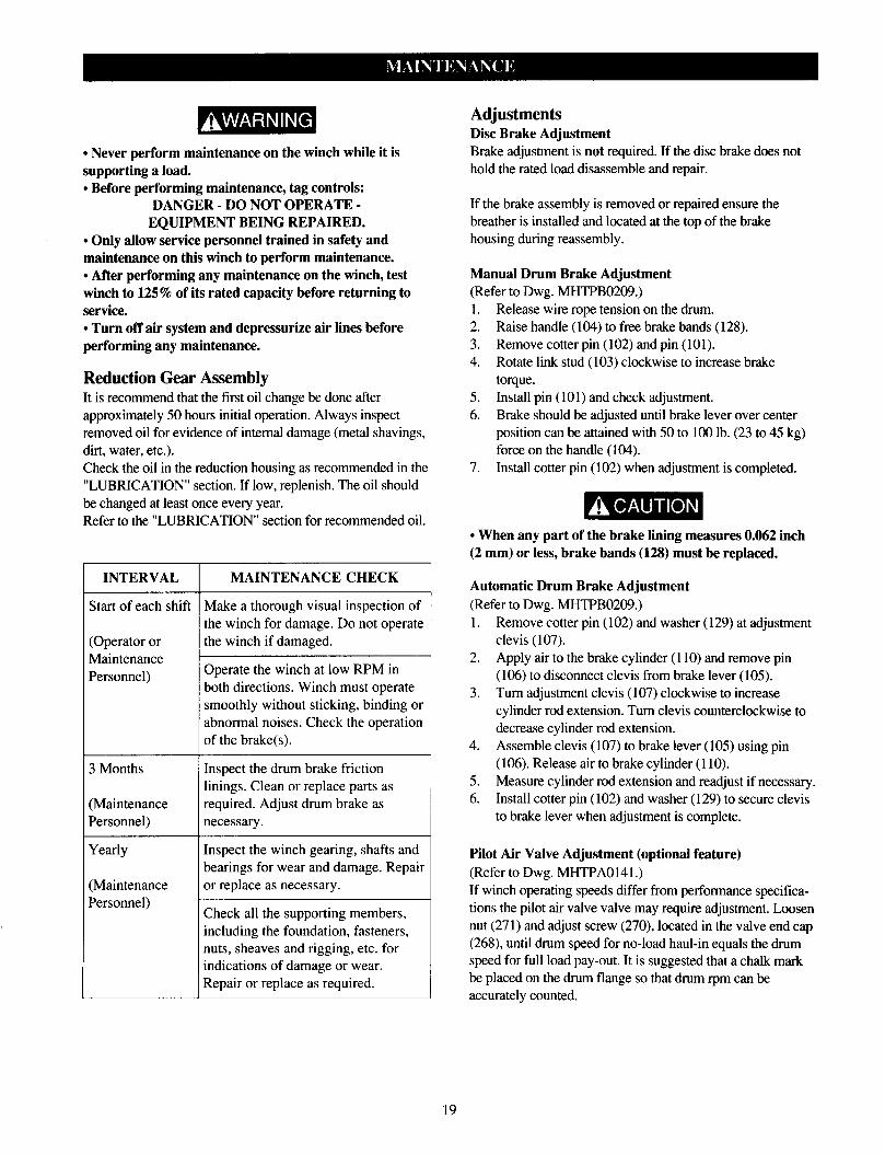
l Never perform maintenance on the winch while it is Brake adjustment is not required. If the disc brake does not
supporting a load. hold the rated load disassemble and repair.
l Before performing maintenance, tag controls: DANGER - DO NOT OPERATE -
EQUIPMENT BEING REPAIRED. l Only allow service personnel trained in safety and maintenance on this winch to perform maintenance. l After performing any maintenance on the winch, test winch to 125% of its rated capacity before returning to service. l Turn off air system and depressurize air lines before performing any maintenance.
If the brake assembly is removed or repaired ensure the breather is installed and located at the top of the brake housing during reassembly.
Reduction Gear Assembly It is recommend that the first oil change be done after approximately 50 hours initial operation. Always inspect removed oil for evidence of internal damage (metal shavings,
dirt, water, etc.). Check the oil in the reduction housing as recommended in the “LUBRICATION” section. If low, replenish. The oil should
be changed at least once every year. Refer to the “LUBRICATION” section for recommended oil.
Manual Drum Brake Adjustment (Refer to Dwg. MHTPB0209.) 1. Release wire rope tension on the drum. 2. Raise handle (104) to free brake bands (128).
3. Remove cotter pin (102) and pin (101). 4. Rotate link stud (103) clockwise to increase brake
torque.
5. Install pin (101) and check adjustment.
6. Brake should be adjusted until brake lever over center position can be attained with 50 to 100 lb. (23 to 45 kg) force on the handle (104).
7. Install cotter pin (102) when adjustment is completed.
INTERVAL MAINTENANCE CHECK
Start of each shift Make a thorough visual inspection of the winch for damage. Do not operate
Operator or the winch if damaged.
Maintenance Personnel)
Operate the winch at low RPM in both directions. Winch must operate
smoothly without sticking, binding or abnormal noises. Check the operation
of the brake(s).
3 Months
Maintenance Personnel)
Yearly
(Maintenance Personnel)
Inspect the drum brake friction linings. Clean or replace parts as required. Adjust drum brake as necessary.
Inspect the winch gearing, shafts and bearings for wear and damage. Repair
or replace as necessary.
Check all the supporting members, including the foundation, fasteners, nuts, sheaves and rigging, etc. for indications of damage or wear.
Repair or replace as required.
Adjustments Disc Brake Adjustment
l When any part of the brake lining measures 0.062 inch (2 mm) or less, brake bands (128) must be replaced.
Automatic Drum Brake Adjustment (Refer to Dwg. MHTPB0209.)
1. Remove cotter pin ( 102) and washer (129) at adjustment
clevis (107). 2. Apply air to the brake cylinder (110) and remove pin
(106) to disconnect clevis from brake lever (105).
3. Turn adjustment clevis (107) clockwise to increase cylinder rod extension. Turn clevis counterclockwise to decrease cylinder rod extension.
4. Assemble clevis (107) to brake lever (105) using pin
(106). Release air to brake cylinder (110). 5. Measure cylinder rod extension and readjust if necessary. 6. Install cotter pin (102) and washer (129) to secure clevis
to brake lever when adjustment is complete.
Pilot Air Valve Adjustment (optional feature) (Refer to Dwg. MHTPA0141.) If winch operating speeds differ from performance specifica-
tions the pilot air valve valve may require adjustment. Loosen
nut (271) and adjust screw (270), located in the valve end cap (268), until drum speed for no-load haul-in equals the drum speed for full load pay-out. It is suggested that a chalk mark be placed on the drum flange so that drum rpm can be accurately counted.
19

Disassembly General Disassembly Instructions The following instructions provide the necessary information to disassemble, inspect, repair, and assemble the winch. Parts drawings are provided in the parts section. If a winch is being completely disassembled for any reason, follow the order of the topics as they are presented. It is recommended that all maintenance work on the winch be
performed in a clean dust free work area. In the process of disassembling the winch, observe the following:
Never disassemble the winch any further than is necessary to accomplish the needed repair. A good part
can be damaged during the course of disassembly. Never use excessive force when removing parts. Tapping
gently around the perimeter of a cover or housing with a soft hammer, for example, is sufficient to break the seal.
Do not heat a part with a flame to free it for removal, unless the part being heated is already worn or damaged beyond repair and no additional damage will occur to
other parts.
In general, the winch is designed to permit easy disassembly
and assembly. The use of heat or excessive force should not be required.
4.
5.
6.
7.
8.
Keep the work area as clean as practical, to prevent dirt and other foreign matter from getting into bearings or other moving parts.
All seals and ‘0’ rings should be discarded once they
have been removed. New seals and ‘0’ rings should be used when assembling the winch. When grasping a part in a vise, always use leather-
covered or copper-covered vise jaws to protect the surface of the part and help prevent distortion. This is
particularly true of threaded members and housings. Do not remove any part which is a press fit in or on a
subassembly unless the removal of that part is necessary
for repairs or replacement.
When removing ball bearings from shafts, it is best to use a bearing puller. When removing bearings from hous-
ings, drive out the bearing with a sleeve slightly smaller than the outside diameter of the bearing. The end of the sleeve or pipe which contacts the bearing must be square.
Protect bearings from dirt by keeping them wrapped in clean cloths.
Winch Disassembly
(Refer to Dwg. MHTPC0214.) 1. Remove the wire rope from the drum.
2. Operate the winch to position reduction gear drain plug
at its lowest position. 3. Relieve pressure in the air lines by operating the winch
control several times after the air supply has been turned off.
l Shut off, bleed down and disconnect the air supply line before performing any disassembly procedures.
4. Disconnect and tag the air lines. 5. Remove the winch from its mounting and take to a
suitable work area before beginning disassembly.
6. Remove lower case drain plug (464) in motor housing
(463) on FA2 winches or drain plug (225) on motor housing (217) in FA2.5 winches and allow the oil to drain into a suitable container. Loosen fill cap (462) on FA2 winches or fill cap (210) on FA2.5 winches to vent the motor housing.
7. Drain oil from the gear reduction assembly by removing
pipe plug (48) when positioned at its lowest point. 8. For winches with a disc brake remove pipe plug (24) in
brake housing (21) to drain brake oil. If the winch is equipped with a drum band brake the winch outboard
end (opposite the motor end) must be elevated to prevent draining oil from contaminating the brake band lining.
l The FA2 air motor weighs approximately 117 lb. (53 kg). The FA2.5 air motor weighs approximately 260 lb. (118 kg). Adequately support the air motor before removing the motor mounting capscrews.
9. Remove drum band brake, drum guard and any other
externally mounted winch attachments. 10. Remove the capscrews and lockwashers securing the
motor assembly to the motor adapter. Using a hoist to
support the motor, pull the motor straight away from the winch. Reference the applicable Motor Disassembly section if motor disassembly is required.
Instructions 11 through 17 apply only to winches with a disc brake.
11.
12.
13. 14.
15.
16.
Alternately and evenly loosen capscrews (4) on FA2 winches, or capscrews (1) on FA2.5 winches until the
brake spring tension has been released. Remove capscrews and motor adapter (6). Remove the brake housing (21). If the brake housing
sticks, tap it with a brass hammer until the pieces
separate. Note the position of all brake pieces for reassembly. Remove friction plates (16) and drive plates (17).
Remove springs (9) from brake piston (10). Remove brake piston (10) from brake housing (21). Tap lightly with a plastic mallet to separate parts if necessary. Remove seals (11) and (12) from brake piston (10).
20
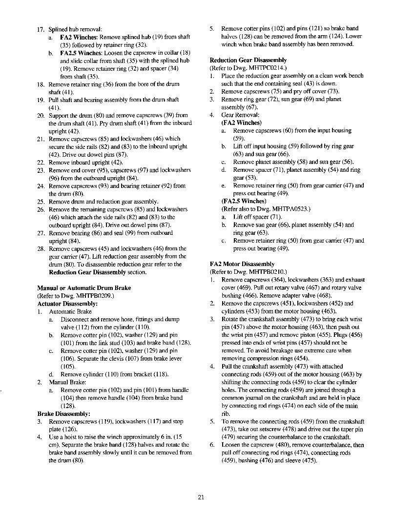
17. Splined hub removal:
a. FA2 Winches: Remove splined hub (19) from shaft (35) followed by retainer ring (32).
b. FA2.5 Winches: Loosen the capscrew in collar (18) and slide collar from shaft (35) with the splined hub (19). Remove retainer ring (32) and spacer (34) from shaft (35).
18. Remove retainer ring (36) from the bore of the drum shaft (41).
19. Pull shaft and bearing assembly from the drum shaft
(41). 20. Support the drum (80) and remove capscrews (39) from
the drum shaft (41). Pry drum shaft (41) from the inboard upright (42).
21. Remove capscrews (85) and lockwashers (46) which secure the side rails (82) and (83) to the inboard upright (42). Drive out dowel pins (87).
22. Remove inboard upright (42).
23. Remove end cover (95), capscrews (97) and lockwashers (96) from the outboard upright (84).
24. Remove capscrews (93) and bearing retainer (92) from the drum (80).
25. Remove drum and reduction gear assembly.
26. Remove the remaining capscrews (85) and lockwashers (46) which attach the side rails (82) and (83) to the outboard upright (84). Drive out dowel pins (87).
27. Remove bearing (86) and seal (99) from outboard upright (84).
28. Remove capscrews (45) and lockwashers (46) from the gear carrier (47). Lift reduction gear assembly from the drum (80). To disassemble reduction gear refer to the
Reduction Gear Disassembly section.
Manual or Automatic Drum Brake (Refer to Dwg. MHTPB0209.) Actuator Disassembly: 1. Automatic Brake
a. Disconnect and remove hose, fittings and dump valve (112) from the cylinder (110).
b. Remove cotter pin (102), washer (129) and pin
(10l) from the link stud (l03) and brake band (128).
C. Remove cotter pin (102), washer (129) and pin (106). Separate the clevis (107) from brake lever
(105). d. Remove cylinder (110) from bracket (118).
2. Manual Brake:
a. Remove cotter pin (102) and pin (101) from handle ( 104) then remove handle (104) from brake band
(128).
Brake Disassembly: 3. Remove capscrews (119) lockwashers (117) and stop
plate ( 126). 4. Use a hoist to raise the winch approximately 6 in. (15
cm). Separate the brake band (128) halves and rotate the brake band assembly slowly until it can be removed from
the drum (80).
5. Remove cotter pins ( 102) and pins ( 12 1) so brake band
halves ( 128) can be removed from the arm ( 124). Lower winch when brake band assembly has been removed.
Reduction Gear Disassembly (Refer to Dwg. MHTPC0214.) 1. Place the reduction gear assembly on a clean work bench
such that the end containing seal (43) is down. 2. Remove capscrews (75) and pry off cover (73). 3. Remove ring gear (72), sun gear (69) and planet
assembly (67). 4. Gear Removal:
(FA2 Winches) a. Remove capscrews (60) from the input housing
(59). b. Lift off input housing (59) followed by ring gear
(63) and sun gear (66). c. Remove planet assembly (58) and sun gear (56).
d. Remove spacer (71), planet assembly (54) and ring gear (53).
e. Remove retainer ring (50) from gear carrier (47) and press out bearing (49).
(FA2.5 Winches) (Refer also to Dwg. MHTPA0523.)
a. Lift off spacer (71).
b. Remove sun gear (66) planet assembly (54) and ring gear (63).
C. Remove retainer ring (50) from gear carrier (47) and press out bearing (49).
FA2 Motor Disassembly (Refer to Dwg. MHTPB0210.) 1. Remove capscrews (364), lockwashers (363) and exhaust
cover (469). Pull out rotary valve (467) and rotary valve bushing (466). Remove adapter valve (468).
2. Remove the capscrews (451), lockwashers (452) and
cylinders (453) from the motor housing (463). 3. Rotate the crankshaft assembly (473) to bring each wrist
pin (457) above the motor housing (463), then push out the wrist pin (457) and remove piston (455). Plugs (456)
pressed into ends of wrist pins (457) should not be removed. To avoid breakage use extreme care when
removing compression rings (454).
4. Pull the crankshaft assembly (473) with attached connecting rods (459) out of the motor housing (463) by
shifting the connecting rods (459) to clear the cylinder
holes. The connecting rods (459) are joined through a common journal on the crankshaft and are held in place by connecting rod rings (474) on each side of the main
rib. 5. To remove the connecting rods (459) from the crankshaft
(473), take out setscrew (478) and drive out the taper pin (479) securing the counterbalance to the crankshaft.
6. Loosen the capscrew (480), remove counterbalance, then pull off connecting rod rings (474), connecting rods (459), bushing (476) and sleeve (475).
21
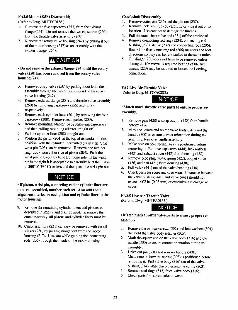
FA2.5 Motor (K5B) Disassembly (Refer to Dwg. MHTPC0156.)
1. Remove the five capscrews (253) from the exhaust flange (254). Do not remove the two capscrews (256) from the throttle valve assembly (260).
2. Remove the rotary valve housing (247) by pulling it out of the motor housing (2 17) as an assembly with the exhaust flange (254).
l Do not remove the exhaust flange (254) until the rotary valve (250) has been removed from the rotary valve housing (247).
3.
4.
5.
6.
7.
8.
Remove rotary valve (250) by pulling it out from the
assembly through the motor housing end of the rotary valve housing (247).
Remove exhaust flange (254) and throttle valve assembly (260) by removing capscrews (255) and (257), respectively.
Remove each cylinder head (201) by removing the four capscrews (200). Remove head gasket (209).
Remove mounting adapter (6) by removing capscrews
and then pulling mounting adapter straight off. Pull the cylinder liner (208) straight out. Position the piston (204) at the top of its stroke. In this
position, with the cylinder liner pulled out in step 7, the wrist pin (203) can be removed. Remove one retainer ring (205) from either side of piston (204). Push the
wrist pin (203) out by hand from one side. If the wrist pin is too tight it is acceptable to carefully heat the piston
to 200” F (93” C) or less and then push the wrist pin out.
l If piston, wrist pin, connecting rod or cylinder liner are to be re-assembled, number each set. Also add radial alignment marks for each piston and cylinder liner to the motor housing.
9. Remove the remaining cylinder liners and pistons as
described in steps 7 and 8 as required. To remove the crank assembly, all pistons and cylinder liners must be
removed.
10. Crank assembly (231) can now be removed with the oil
slinger (230) by pulling straight out from the motor housing (217). Use care while guiding the connecting rods (206) through the inside of the motor housing.
Crankshaft Disassembly 1. Remove cotter pin (236) and the pin nut (237).
2. Remove lock pin (235) by carefully driving it out of its
location. Use care not to damage the threads.
3. Pull the crankshaft valve end (231) off the crankshaft.
4. Remove connecting rod rings (234), connecting rod bushing (233), sleeve (232) and connecting rods (206). Record the five connecting rod (206) numbers and foot directions so they can be re-installed in the same order.
5. Oil slinger (230) does not have to be removed unless
damaged. If removal is required heating of the five
screws (229) may be required to loosen the Loctite® connection.
FA2 Live Air Throttle Valve (Refer to Dwg. MHTPA0203.)
l Match mark throttle valve parts to ensure proper re- assembly.
1.
2.
3.
4.
5. 6.
Remove pins (428) and tap out pin (428) from handle bracket (426).
Mark the square end on the valve body (3 16) and the
handle (300) to ensure correct orientation during re- assembly. Remove handle assembly. Make note on how spring (427) is positioned before removing it. Remove capscrews (444), lockwashers
(443) and exhaust cover (442) from housing (438). Remove pipe plug (434), spring (422), poppet valve
(436) and ball (421) from housing (438). Pull valve (441) out of the valve bushing (440).
Check parts for score marks or wear. Clearance between the valve bushing (440) and valve (441) should not
exceed .002 in. (0.05 mm) or excessive air leakage will occur.
FA2.5 Live Air Throttle Valve (Refer to Dwg. MHTPA0165.)
l Match mark throttle valve parts to ensure proper re- assembly.
1. Remove the two capscrews (302) and lockwashers (304)
that hold the valve body retainer (305).
2. Mark the square end on the valve body (3 16) and the handle (300) to ensure correct orientation during re-
assembly.
3. Drive out pin (301) and remove handle (300). 4. Make note on how the spring (303) is positioned before
removing it. Pull valve body (3 16) out of the valve bushing (314) while disconnecting the spring (303).
5. Remove seal rings (315) from valve body (316).
6. Check parts for score marks or wear.
22

7. Measure clearance between the valve bushing (314) and
valve body (316). To prevent excessive air leakage, the maximum allowable clearance is 0.002 inch (0.05 mm).
Cleaning, Inspection and Repair Clean all winch component parts in solvent (except the drum brake bands and disc brake friction plates). The use of a stiff bristle brush will facilitate the removal of accumulated dirt and sediments on the housings, frame and drum. If bushings have been removed it may be necessary to carefully remove old Loctite® from the bushing bores. Dry each part using low
pressure, filtered compressed air. Clean the drum brake band using a wire brush or emery cloth. Do not wash the drum brake band in liquid. If the drum brake band lining is oil
soaked, it must be replaced.
Inspection All disassembled parts should be inspected to determine their fitness for continued use. Pay particular attention to the following:
1. Inspect all gears for worn, cracked, or broken teeth. 2. Inspect all bushings for wear, scoring, or galling. 3. Inspect shafts for ridges caused by wear. If ridges caused
by wear are apparent on shafts, replace the shaft.
4. Inspect all threaded items and replace those having damaged threads.
5. Inspect the drum band brake lining for oil, grease and glazing. If the drum band brake lining is oil-soaked replace the brake bands as a set. Remove glazed areas of band brake lining by sanding lightly with a fine grit
emery cloth. 6. Measure the thickness of the drum band brake lining. If
the drum brake band linings are less than 0.062 inch (2 mm) thick anywhere along the edges replace the brake bands ( 128) as a set.
Repair Actual repairs are limited to the removal of small burrs and other minor surface imperfections from gears and shafts. Use a fine stone or emery cloth for this work.
1. Worn or damaged parts must be replaced. Refer to the applicable parts listing for specific replacement parts information.
2. Inspect all remaining parts for evidence of damage.
Replace or repair any part which is in questionable condition. The cost of the part is often minor in comparison with the cost of redoing the job.
3. Smooth out all nicks, burrs, or galled spots on shafts, bores, pins, or bushings.
4. Examine all gear teeth carefully, and remove nicks or burrs.
5. Polish the edges of all shaft shoulders to remove small nicks which may have been caused during handling.
6. Remove all nicks and burrs caused by lockwashers.
Assembly General instructions
l use all new gaskets and seals.
l replace worn parts.
l assemble parts using match marks attached during
disassembly. Compare replacement parts with originals to identify installation alignments.
l lubricate all internal parts with a mixture of half SAE 20W oil and half molydenum disulfide lubricant compound (eg. SIP).
FA2 Live Air Throttle Valve Assembly (Refer to Dwg. MHTPA0203.)
l During assembly align parts using match marks made during disassembly.
5.
6.
7.
Install valve (441) and valve bushing (440) into the
housing (438). Install ball (421), poppet valve (436), spring (422) and pipe plug (434) in housing (438).
If screws (430) were removed during disassembly, reinstall in housing (438) and handle bracket (426). Place spring (422) and ball (421) in handle bracket (426).
Depress spring and ball with handle (420) and install pin (425) with washers (424) and pins (423). Install spring (427) and handle assembly on square shaft
of valve (441) taking note ofthe match marks put on during disassembly. The ends of the spring (427) must straddle the screw (430) on handle bracket (426). Secure
handle assembly to valve with pins (429) and (428). Install sleeves (432) and capscrews (43 1) on housing (438). Attach exhaust cover (442) to housing (438) with
capscrews (444) and lockwashers (443). Check throttle handle moves fully left and right without
sticking or binding. Throttle handle should center, by spring force, automatically when released.
FA2.5 Live Air Throttle Valve Assembly (Refer to Dwg. MHTPA0165.)
l During assembly align parts using match marks made during disassembly.
1. Install seal rings (3 15) on each end of valve body (316). 2. Install valve body (3 16) into valve bushing (3 14). 3. Insert valve bushing (3 14) into valve housing (311).
Ensure ports in bushing and flat cutout in valve body are properly aligned with housing ports as shown in Dwg. MHTPA0165.
4. Install valve body retainer (305) with two capscrews (302) and lockwashers (304). Torque capscrews to 25 ft
lbs (3.5 kgm). 5. If removed, re-install spring retaining stud (306) and
torque to 25 ft lbs (3.5 kgm).
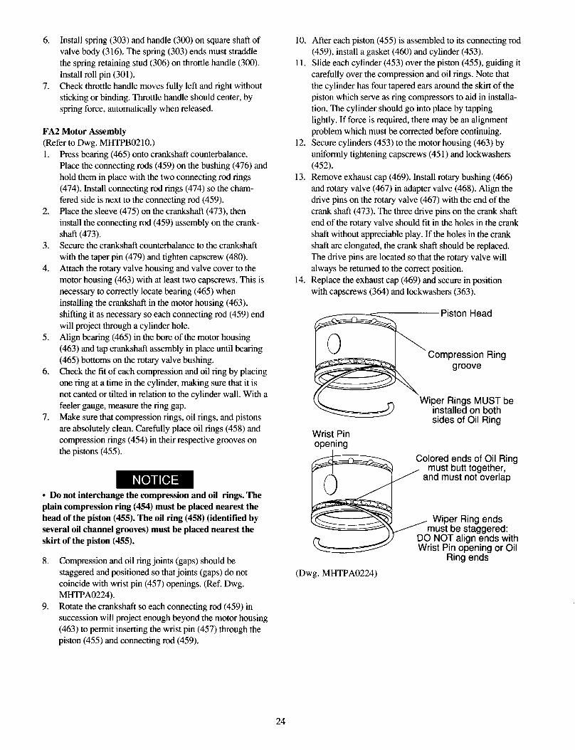
6. Install spring (303) and handle (300) on square shaft of valve body (316). The spring (303) ends must straddle the spring retaining stud (306) on throttle handle (300).
Install roll pin (301). 7. Check throttle handle moves fully left and right without
sticking or binding. Throttle handle should center, by spring force, automatically when released.
FA2 Motor Assembly (Refer to Dwg. MHTPB0210.)
1.
2.
3.
4.
5.
6.
7.
Press bearing (465) onto crankshaft counterbalance. Place the connecting rods (459) on the bushing (476) and hold them in place with the two connecting rod rings
(474). Install connecting rod rings (474) so the cham- fered side is next to the connecting rod (459). Place the sleeve (475) on the crankshaft (473), then install the connecting rod (459) assembly on the crank-
shaft (473). Secure the crankshaft counterbalance to the crankshaft with the taper pin (479) and tighten capscrew (480).
Attach the rotary valve housing and valve cover to the
motor housing (463) with at least two capscrews. This is necessary to correctly locate bearing (465) when installing the crankshaft in the motor housing (463), shifting it as necessary so each connecting rod (459) end
will project through a cylinder hole.
Align bearing (465) in the bore of the motor housing (463) and tap crankshaft assembly in place until bearing (465) bottoms on the rotary valve bushing. Check the fit of each compression and oil ring by placing one ring at a time in the cylinder, making sure that it is
not canted or tilted in relation to the cylinder wall. With a feeler gauge, measure the ring gap.
Make sure that compression rings, oil rings, and pistons are absolutely clean. Carefully place oil rings (458) and compression rings (454) in their respective grooves on the pistons (455).
l Do not interchange the compression and oil rings. The plain compression ring (454) must be placed nearest the head of the piston (455). The oil ring (458) (identified by several oil channel grooves) must be placed nearest the skirt of the piston (455).
8. Compression and oil ring joints (gaps) should be
staggered and positioned so that joints (gaps) do not coincide with wrist pin (457) openings. (Ref. Dwg. MHTPA0224).
9. Rotate the crankshaft so each connecting rod (459) in succession will project enough beyond the motor housing (463) to permit inserting the wrist pin (457) through the piston (455) and connecting rod (459).
10. After each piston (455) is assembled to its connecting rod (459), install a gasket (460) and cylinder (453).
11. Slide each cylinder (453) over the piston (455), guiding it
carefully over the compression and oil rings. Note that the cylinder has four tapered ears around the skirt of the piston which serve as ring compressors to aid in installa- tion. The cylinder should go into place by tapping
lightly. If force is required, there may be an alignment problem which must be corrected before continuing.
12. Secure cylinders (453) to the motor housing (463) by uniformly tightening capscrews (45 1) and lockwashers (452).
13. Remove exhaust cap (469). Install rotary bushing (466) and rotary valve (467) in adapter valve (468). Align the
drive pins on the rotary valve (467) with the end of the crank shaft (473). The three drive pins on the crank shaft
end of the rotary valve should fit in the holes in the crank shaft without appreciable play. If the holes in the crank
shaft are elongated, the crank shaft should be replaced.
The drive pins are located so that the rotary valve will always be returned to the correct position.
14. Replace the exhaust cap (469) and secure in position
with capscrews (364) and lockwashers (363).
Piston Head
Compression Ring groove
Wrist Pin opening
‘Wiper Rings MUST be installed on both sides of Oil Ring
Colored ends of Oil Ring must butt together,
and must not overlap
, Wiper Ring ends
(Dwg. MHTPA0224)
24
FA2.5 Motor (K5B) Assembly (Refer to Dwg. MHTPC0156.) 1.
2.
3.
4. 5.
10.
11.
12.
13.
14. 15.
Assemble throttle valve assembly (260), gasket (248) and exhaust flange (254) to rotary valve housing (247) using four capscrews (257) and lockwashers (258). Install the two capscrews (255) and lockwashers (256) that attach exhaust flange (254) to throttle valve housing. Tighten capscrews (255 and 257) to 25 ft lbs (3.5 kgm). Throttle handle should move fully left and right without
sticking or binding, and should center (by spring force) automatically when released. Assemble bearing (252) to rear of rotary valve (250) by pressing only on the inner race of the bearing. With the exhaust flange (254) down install rotary valve (250) into rotary valve housing (247). Slide rotary valve out of the
rotary valve housing far enough to install seal ring (25 1) on the crank shaft end of the rotary valve (250). Slide
rotary valve back into the rotary valve housing (247). Install ‘0’ ring (244) into motor housing (217). Install the rotary valve housing gasket (243) onto rotary valve housing (247). With the exhaust flange down on the bench, install motor housing (217) on to rotary valve housing (247). Check for any evidence of damage to ‘0
ring (244) when the rotary valve housing is fully engaged. Install and tighten capscrews (253) to 50 ft lbs
(7 km). If removed, press crank bearing (228) on crank assembly (23 1). Apply pressure only on the inner race of the
bearing. Place crank assembly (231) on a work bench with the oil
slinger (230) down and slide the sleeve (232) (with tang up) on the crankpin.
Slide connecting rod bushing (233) over the sleeve (232) and first connecting rod ring (234) with the chamfer up. Install the connecting rods (206) in the same order as removed, with all feet pointing in the same direction,
using the first connecting rod ring (234) to hold one side of the connecting rod feet.
Slide the second connecting rod ring (234) over the other side of the connecting rod feet with the chamfer on the ring facing down (toward the stem of the connecting rod). Slide the crank shaft valve end over the crankpin while
simultaneously aligning the tang on the sleeve (232) with the slot in the crank shaft.
Rotate and position the crank shaft valve end relative to the crankpin to allow installation of the lock pin (235). Tap the lock pin (235) in place and install the pin nut (237). Torque nut to 60 ft lbs (8.3 kgm).
Install cotter pin (236). Install roll pin (240) and bearing (228) into the valve end of the crank shaft.
16. Check that all connecting rods move freely around the
crank. Position the crank assembly (23 1) into the motor housing (217) with the bearing (228) seated and
connecting rods (206) centered in the cylinder holes.
l Make certain that the roll pin (240) and the three lugs on the rotary valve (250) line up with the corresponding hole and lugs on the crank shaft. l Do not allow the rotary valve (250) to slide back in rotary valve housing (247). If the rotary valve slides in too far, the seal ring (251) will lock-up in the internal grooves of the rotary valve housing (247) and restrict further assembly.
17.
18.
19.
20.
21.
Rotating the crank assembly, position one connecting rod (206) is at the top of its stroke. Install a piston (204) with
its rings (202 and 207) to the connecting rod (206) with wrist pin (203) and retaining rings (205). Install a new cylinder head gasket (209) before installing the cylinder liner (208).
Install the cylinder liner (208) over the piston (204) by compressing both piston rings (202 and 207) with a
single band ring compressor. Install cylinder head (201) over the cylinder and secure
cylinder head to motor housing (217) with four capscrews (200). Torque capscrews to 60 ft lbs (8.3
km). Repeat Steps 17 through 20 with the remaining cylinders.
l When installing the two lowest cylinder heads (201), use seal washers on capscrews (200).
22.
23.
24.
25.
26.
Rotate motor by hand. Motor should rotate without binding. Install mounting flange (216) and gasket (226) on the
front of the motor housing (217). Make sure notches on
both parts are aligned. Temporarily install capscrews and nuts finger tight to retain motor adapter (6).
Install eye bolts (2 13) and vent cap assemblies (2 10) in the motor housing (2 17).
Ensure oil drain and level plugs are installed.
25

FA2 Reduction Gear Assembly Drum Brake Assembly (Refer to Dwg. MHTPC0214.) (Ref. Dwg. MHTPB0209)
1.
2.
3.
4.
5.
6.
7.
8.
9.
10.
11.
12. 13. 14.
15.
16.
Lubricate and install ‘0’ rings (62) on ring gear (72). Assemble ring gear (72), cover (73) and spacer (7 1). Check dowel and capscrew holes are aligned. Drive dowels (74) into assembly so they are flush with
the cover (73). Position assembled parts vertically with the cover (73) down. Install planet assembly (67) and gear (69) into ring
gear (72). Press bushing (55) into sun gear (66) and install sun gear (66) into planet assembly (67). Lubricate and install ‘0’ rings (62) on ring gear (63). Install ring gear on spacer (7 1) being careful not to damage the ‘0’ ring. Align dowel and capscrew holes.
Tap dowels (70) into ring gear (63) and spacer (71). Leave approximately 0.37 inch (9 mm) exposed for
engagement with input housing (59). Install planet assembly (58) so planet gear teeth mesh in the ring gear (63) and with the sun gear (66). Carefully install input housing (59) so it locates on
dowels (70). Tilt assembly on the work bench and install capscrews (75) with Loctite® 242 and torque to 32 ft lbs
(5 km). Return assembly to the vertical position. Install bushing (55) and retainer ring (57) on sun gear (56) and install sun gear (56) in planet assembly (58).
Lubricate and install ‘0’ ring (51) on ring gear (53). Line up dowel and capscrew holes and install ring gear (53) on input housing (59) being careful not to damage ‘0 ring (5 1). Install planet assembly (54) so planet gear teeth mesh with ring gear and sun gear.
Lubricate and install ‘0’ ring (5 1) on ring gear (53). Install oil plugs (61) in input housing (59). Press bearing (49) into bore of gear carrier (47). Install retainer ring (50). Install gear carrier (47) on ring gear (53) being careful not to damage ‘0’ ring (5 1). Check capscrew and dowel
holes are lined up. Install capscrews (60) with Loctite® 242. Torque capscrews (60) to 94 ft lbs (13 kgm). Tap dowels (52) through ring gear (53), input housing
(59) and gear carrier (47) until they are just below the flange surface of the gear carrier (47).
FA2.5 Reduction Gear Assembly (Refer to Dwgs. MHTPC0214 and MHTPA0523.) 1. Lubricate and install ‘0’ rings (62) on ring gear (72).
Assemble ring gear (72), cover (73) and spacer (71). Check dowel and capscrew holes are aligned.
2. Drive dowels (74) into assembly so they are flush with the cover (73).
3. Position assembled parts vertically with the cover (73) down. Install planet assembly (67) and gear (69) into ring
gear (72). 4. Press bushing (55) into sun gear (66) and install sun gear
(66) into planet assembly (67).
1.
2.
3.
4.
5.
6.
7.
8.
9.
10.
Install pivot bracket ( 122) on the end of arm ( 124) with pin ( 12 1 ), washer ( 123) and cotter pin ( 102). Recessed
side of the threaded hole must be toward the band side. Install connecting link ( 125) on the arm ( 124) and secure in position with pin ( 12 1 ), washer ( 123) and cotter pin ( 12 1). Assemble connecting link ( 125) so curved surface matches contour of the brake band. Install halves of brake band ( 128) to the connecting link (125) and secure with pins (l0l), (121) and cotter pins (102). Lift the winch assembly, with a suitable hoist,
approximately 6 inches ( 15 cm) off the floor or work bench. Position the brake band sub-assembly around the brake
diameter on the drum (80) so the arm (124) lays at the bottom. When positioned, lower the winch.
Mount pivot bracket (122) on the inside surface of the side rail (130) and secure in position with capscrews
(116) and lockwashers (117). Screw link stud into handle and install the handle (104) in the lug on the end of the brake band (128). Lubricate the pivot points being careful not to get grease on the
brake band lining. Pull the halves of the brake band together and install pin
( 101) through the lug on band (128) and the adjusting
screw (103) of the handle assembly. Install stop plate ( 126) on the inside of the side rail ( 13 1) with capscrews (119) and washers (117). Install adjusting screw ( 127) and locknut ( 120) through the side rail ( 13 1) and stop plate ( 126) until it contacts the arm ( 124). Adjust brake as described at the start of the
“MAINTENANCE” section.
Automatic Drum Brake Actuator Assembly 11. Install bracket ( 118) on side rail (139) with capscrews
(116) and lockwashers (117). 12. Screw nut (108) and clevis (107) onto cylinder rod.
13. Attach brake lever (105) to brake band (128). 14. Install cylinder (110) so it connects with bracket (118)
and brake lever (105). Use pins (106), washers (129) and cotter pins (102) to secure in position.
15. Install dump valve (112) fittings and hose (115) to the
cylinder (110). 16. Adjust automatic brake as described at the start of the
“MAINTENANCE” section.
26

Winch Assembly (Refer to Dwg. MHTPC0214.)
1.
2.
3.
4.
5.
Clean both mating surfaces on the inboard upright (42) and install drum shaft (41) through the bore aligning the dowel pin holes. Install dowel pins (40) flush or slightly below the surface of the drum shaft (41). Install capscrews (39) with Loctite® 242 and torque to 44 ft lb (6 kgm) on FA2 winches or 85 ft lb (12 kgm) on FA2.5 winches.
Press bearing (37) onto the shaft (35) using Loctite® 609. On FA2.5 winches install retainer ring (38).
Install shaft and bearing into the drum shaft (41) so smaller splined end enters first. On FA2.5 winches install retainer ring (36) in bore of drum shaft (41).
Instructions 6 through 17 cover winches with a disc brake. For winches without a disc brake skip to instruction 18.
6.
7.
8. 9.
10.
11.
12.
13.
On FA2 winches install retainer ring (32) and splined
hub (19) on shaft (35) so splined side of outside diameter goes on first. Seat splined hub ( 19) against retainer ring
(32). On FA2.5 winches install spacer (34) on shaft (35). Install splined hub (19) so splined side on outside diameter goes on first. Install capscrew in locking ring
(18) and place on shaft (35). Maintain pressure on the locking ring to keep it against the splined hub (19) and tighten capscrew in locking ring (18). Lubricate and install ‘0’ ring (33) on hub of drum shaft.
Install brake housing (21) on drum shaft (41) being careful not to damage ‘0’ ring (33). Position brake housing (21) so brake port is in the 2 o’ clock position (as viewed from the motor end). Install drain plug (24) in brake housing (21) at the 6
o’clock position. Install fitting (22) and breather (23) in the top of the
brake housing (2 1). Lubricate friction plates (16) with a light SAE 10W motor oil and install friction plates ( 16) and drive plates (17) in brake housing (21). Begin with a friction plate (16) then alternate between drive plates (17) and friction plates (16). Ensure the splined teeth mesh. Do not use
force. Lubricate and install seals ( 11) and ( 12) in brake piston (10) grooves so seal lips face each other. Do not overstretch seals during this procedure. Refer to Dwg.
MHTPA0139.
Brake Piston
(Dwg. MHTPA0139)
14.
15.
16.
17.
18.
19.
20.
21.
22.
23.
Install brake piston assembly in brake housing (2 1) so stepped side enters first. Gently tap into position using a soft mallet until seated. Install one brake spring (9) in each of the brake spring holes.
Lubricate and install ‘0’ ring (20) on motor adapter (6) for FA2 winches or in the groove on the brake housing (21) on FA2.5 winches. On FA2.5 winches install the brake reaction plate (8) in
the motor adapter (6). On FA2.5 winches install the seal adapter (15) in the mounting flange (216) if required. On FA2.5 winches two of the threaded holes in the motor
adapter (6) are centered between the mounting bolt holes. Install motor adapter with these two holes in the 6 o’clock position. On FA2 winches the motor adapter is symmetrical and can be mounted in any position. On FA2.5 winches install motor adapter (6) with eight
capscrews (1) using Loctite® 242. Torque to 85 ft lbs (12 kgm). On winches with a disc brake install capscrews evenly to compress brake springs. Do not allow plate to become cocked. Evenly hand tighten all capscrews
before applying final torque. On disc brake equiped winches install shaft extender (7) on end of shaft (35). On FA2.5 winches without disc brake install seal sleeve (14) on shaft (35).
Lubricate and install '0' ring (5) in groove on the motor adapter (6). Ensure seal adapter (15) (FA2.5 only) and oil seal (2) are installed in the bore of the motor assembly. Seal lip must face into the motor assembly.
l The FA2 air motor weighs approximately 117 lb. (53 kg). The FA2.5 air motor weighs approximately 260 lb. (118 kg). Adequately support the air motor while installing the motor mounting capscrews.
27
24.
25.
26.
27.
28.
On FA2 winches mount motor assembly to motor
adapter (6) with capscrews (97) and lockwashers (96). Torque capscrews (97) to 30 ft lbs (4 kgm). On FA2.5 winches, if motor assembly is being mounted
with the winch in a vertical position, install one short bolt and nut to keep motor mounting flange (216) from dropping off. Lower motor assembly carefully onto the shaft. Position throttle assembly at the top. Be careful not
to damage oil seal (2). When correctly positioned remove bolt and nut and lower motor assembly the remaining distance. On FA2.5 winches install the motor assembly to the motor mounting plate using capscrews (4) with Loctite®
242. Torque capscrews to 85 ft lbs (12 kgm). On FA2.5 winches make sure seal sleeve is in place in
drum shaft (41). Due to very thin wall section, use extreme care to prevent damage to the seal sleeve. On winches with a disc brake install fitting (3 1) in dump
valve (30) and screw into the brake release port. Install vented fitting (29) in dump valve (30). Install fitting (25) in valve assembly (260) with elbow (26). Install steel
tube (27) between fitting on the dump valve (30) and
elbow (26).
Drum Assembly 1.
2.
3.
4.
5.
6. 7.
8.
9.
10.
11.
12.
Lay gear carrier (47) on the work bench and install bearing (49), retainer ring (50) and ‘0’ ring (5 1). Align the dowel pins (52) and install reduction gear
assembly to gear carrier (47). Install capscrews (60) on FA2 winches or capscrews (75) on FA2.5 winches and torque to 60 ft lbs (8.3 kgm).
Clean surfaces of the drum (80) and gear carrier (47). Apply Loctite® 5 15 gasket sealant to drum mating surface. Lower reduction gear assembly into drum (80).
Install capscrews (45) and lockwashers (46) with Loctite® 242 and torque to 70 ft lbs (10 kgm) on FA2 winches or 210 ft lbs (29 kgm) on FA2.5 winches. Install fill/drain plugs (48) in gear carrier (47). Apply a thin coat of Loctite® 609 to the outside of seal (43) and install in gear carrier (47). Place drum in an upright position. Carefully lower inboard assembly into the drum (80) making sure splines
on shaft (35) and drum shaft (41) mesh in the drum and reduction gear assembly. Using a ‘C’ clamp, clamp the inboard flange assembly to
the drum flange and place complete assembly in a horizontal position. Clean seal surface and install oil seal (99) in outboard upright (84) with lip toward the drum.
Pack bearing (86) with grease and install in outboard upright (84). Install outboard upright (84) on the drum end. Ensure assembly is kept centered on seal and journal during this step.
13. Install shaft retainer (92) using capscrews (93) with Loctite® 242. Torque to 30 ft lbs (4 kgm).
14. Apply a light coat of Loctite® 5 15 sealant to the mating surface of the outboard upright (84) and install end cover (95) using capscrews (97) and lockwashers (96). Apply a small amount of Loctite® 242 to capscrew (97) threads and torque to 30 ft lbs (4 kgm).
15. Install pipe plug (98) in end cover (95). 16. Install side rails to uprights and loosely secure using
capscrews (85) and lockwashers (46). 17. Tap dowel pins (87) into position so they are flush with
the side rails. 18. Apply Loctite® 242 to capscrews (85) and lockwashers
(46) and torque to 70 ft lbs (9.7 kgm).
Testing Operational Test Prior to initial use, all new, altered or repaired winches shall
be tested to ensure proper operation.
a.
b.
C.
d.
e.
f.
g.
Check oil level in motor, reduction gear assembly and
disc brake are correct. To initially ‘break in’ new or overhauled motors operate
without load, in both directions, for 2 hours at 100 - 200 RPM. New Drum Brake Band Lining Run-in Procedure: All new drum brake band linings require a ‘run-in’ period.
Operate the winch without load in the payout direction
while gradually applying the brake. Allow the brake to slip for approximately one minute. Winch motor may stall as drum brake band lining fully engages. Do not allow brake to overheat. Check operation of brakes. Adjust if necessary as described in the “MAINTENANCE’ section.
Check operation of limit switches, locking devices and all safety devices when equipped. Check foundation mounting fasteners are secure.
Install drum guard when provided.
Load Test Prior to initial use, all new, extensively repaired, or altered
winches shall be load tested by or under the direction of a person trained in the operation and safety of this winch and a written report furnished confirming the rating of the winch.
Test loads shall not be more than 125% of the rated line pull.
To test the winch at 125% of the rated load apply the following load with the wire rope on the first layer of the drum:
FA2 Winch 7223 lb. (3283 kg) FA2.5 Winch 8223 lb. (3738 kg)
28

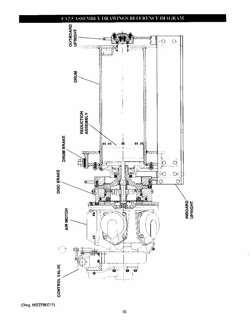
(Dwg. MHTPB0215)

Description Page No.
Winch Drum, Base and FA2 Reduction Gear Assembly Drawing (MHTPC0214) ....................................................... 32 FA2 Reduction Gear Assembly Drawing (MHTPA0523) ................................................................................. 33 Drum, Base and Reduction Gear Assembly Drawing Parts List ......................................................................... 33
Drum, Base and Reduction Gear Assembly Drawing Parts List (continued) ...................................................... 34
Drum, Base and Reduction Gear Assembly Drawing Parts List (continued) ...................................................... 35
Brakes Disc Brake Assembly Drawing (MHTPA0152) . . . . . . . . . . . . . . . . . . . . . . . . . . . . . . . . . . . . . . . . . . . . . . . . . . . . . . . . . . . . . . . . . . . . . . . . . . . . . . . . . . . . . . . . . . . . . . . . 36 Disc Brake Assembly Parts List . . . . . . . . . . . . . . . . . . . . . . . . . . . . . . . . . . . . . . . . . . . . . . . . . . . . . . . . . . . . . . . . . . . . . . . . . . . . . . . . . . . . . . . . . . . . . . . . . . . . . . . . . . . . . . . . . . . . . . . . 37
Drum Brake Assembly Drawing (MHTPB0209) . . . . . . . . . . . . . . . . . . . . . . . . . . . . . . . . . . . . . . . . . . . . . . . . . . . . . . . . . . . . . . . . . . . . . . . . . . . . . . . . . . . . . . . . . . . . . . 38 Drum Brake Assembly Parts List . . . . . . . . . . . . . . . . . . . . . . . . . . . . . . . . . . . . . . . . . . . . . . . . . . . . . . . . . . . . . . . . . . . . . . . . . . . . . . . . . . . . . . . . . . . . . . . . . . . . . . . . . . . . . . . . . . . . . . 39
Motors FA2 Motor Assembly Drawing (MHTPB0210) . . . . . . . . . . . . . . . . . . . . . . . . . . . . . . . . . . . . . . . . . . . . . . . . . . . . . . . . . . . . . . . . . . . . . . . . . . . . . . . . . . . . . . . . . . . . . . . 40 FA2 Motor Assembly Parts List . . . . . . . . . . . . . . . . . . . . . . . . . . . . . . . . . . . . . . . . . . . . . . . . . . . . . . . . . . . . . . . . . . . . . . . . . . . . . . . . . . . . . . . . . . . . . . . . . . . . . . . . . . . . . . . . . . . . . . . . 4 1
FA2.5 Motor Assembly Drawing (MHTPC0156) . . . . . . . . . . . . . . . . . . . . . . . . . . . . . . . . . . . . . . . . . . . . . . . . . . . . . . . . . . . . . . . . . . . . . . . . . . . . . . . . . . . . . . . . . . . . 42 FA2.5 Motor Assembly Parts List . . . . . . . . . . . . . . . . . . . . . . . . . . . . . . . . . . . . . . . . . . . . . . . . . . . . . . . . . . . . . . . . . . . . . . . . . . . . . . . . . . . . . . . . . . . . . . . . . . . . . . . . . . . . . . . . . . . . . 43
FA2.5 Motor Assembly Parts List (continued) . . . . . . . . . . . . . . . . . . . . . . . . . . . . . . . . . . . . . . . . . . . . . . . . . . . . . . . . . . . . . . . . . . . . . . . . . . . . . . . . . . . . . . . . . . . . . . . . . . 44
FA2.5 Motor Assembly Kits List . . . . . . . . . . . . . . . . . . . . . . . . . . . . . . . . . . . . . . . . . . . . . . . . . . . . . . . . . . . . . . . . . . . . . . . . . . . . . . . . . . . . . . . . . . . . . . . . . . . . . . . . . . . . . . . . . . . . . . 44
Air Control Valves FA2 Live Air Control Valve Assembly Drawing (MHTPA0203) and Parts List ............................................... 45
FA2.5 Live Air Control Valve Assembly Drawing (MHTPA0165) and Parts List ............................................ 46
Pilot Air Control Valve (optional) Assembly Drawing (MHTPA0141) and Parts List.. ..................................... 47
FA2 Remote Live Air Control Valve (optional) Assembly Drawing (MHTPA0204) and Parts List ................. .48
FA2.5 Remote Live Air Control Valve (optional) Assembly Drawing (MHTPA0161) and Parts List .............. .49
Remote Pilot Air Control Valve (optional) Assembly Drawings (MHTPA0167) .............................................. 50 Remote Pilot Air Control Valve (optional) Assembly Parts Lists ....................................................................... 5 1
Accessories Muffler Assembly Drawings (MHTPA0515) . . . . . . . . . . . . . . . . . . . . . . . . . . . . . . . . . . . . . . . . . . . . . . . . . . . . . . . . . . . . . . . . . . . . . . . . . . . . . . . . . . . . . . . . . . . . . . . . . . . 52
Muffler Assembly Parts List . . . . . . . . . . . . . . . . . . . . . . . . . . . . . . . . . . . . . . . . . . . . . . . . . . . . . . . . . . . . . . . . . . . . . . . . . . . . . . . . . . . . . . . . . . . . . . . . . . . . . . . . . . . . . . . . . . . . . . . . ...... 53
Pendant Air Control Valve (optional) Assembly Drawing (MHTPA0168) and Parts List . . . . . . . . . . . . . . . . . . . . . . . . . . . . . . . . . 54
Drum Locking Pin (optional) Assembly Drawing (MHTPB0155) and Parts List . . . . . . . . . . . . . . . . . . . . . . . . . . . . . . . . . . . . . . . . . . . . . . 55
Drum Guard Assembly Drawing (MHTPA0205) and Parts List . . . . . . . . . . . . . . . . . . . . . . . . . . . . . . . . . . . . . . . . . . . . . . . . . . . . . . . . . . . . . . . . . . . . . . . 56
Air Preparation Assembly Drawing (MHTPA0223) and Parts List . . . . . . . . . . . . . . . . . . . . . . . . . . . . . . . . . . . . . . . . . . . . . . . . . . . . . . . . . . . . . . . . . . . 57
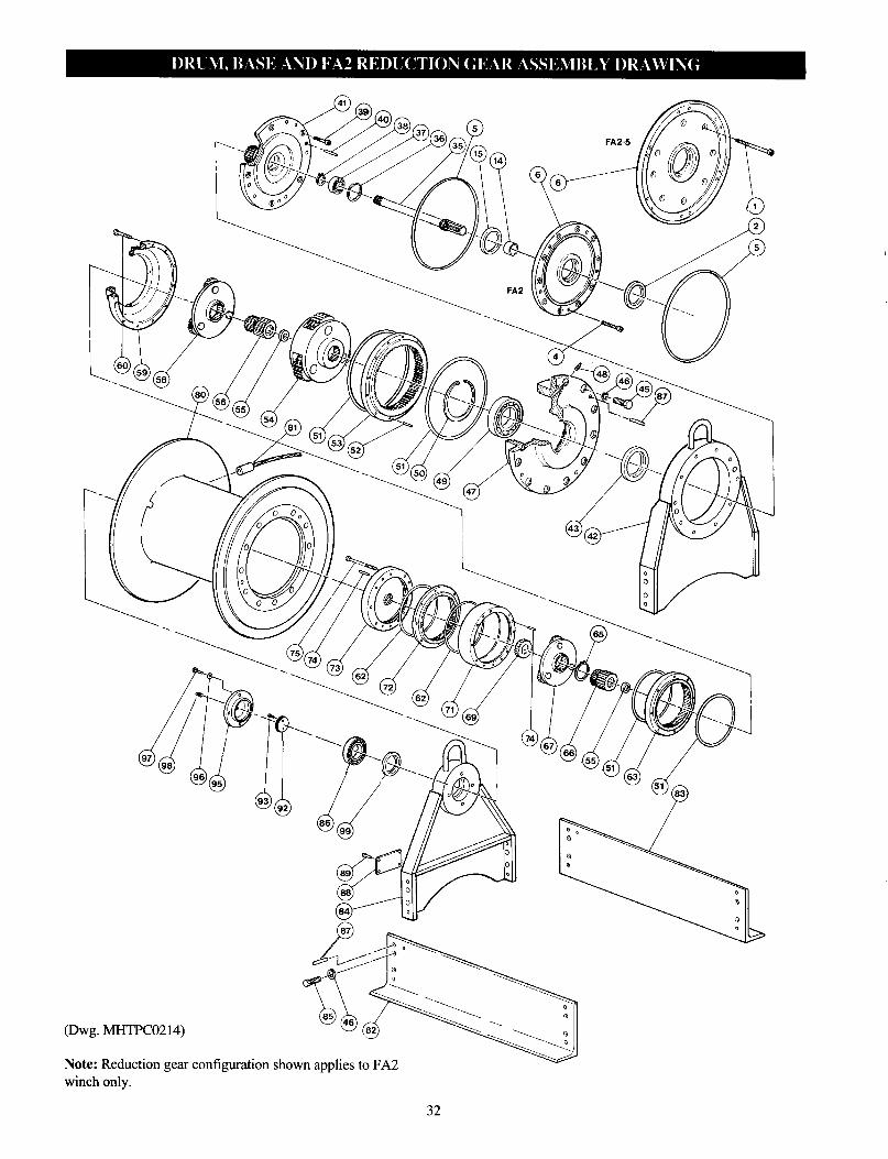
Note: Reduction gear configuration shown applies to FA2 winch only.
32

(Dwg. MHTPA0523)
ITEM DESCRIPTION QUANTITY PART NUMBER
NO. OF PART TOTAL FA2 FA2.5
1 Capscrew (without Disc Brake) 8 I ___ I 52379 I
• 2 Oil Seal 1 52223 51873
4 Capscrew See () 51931 (5) 50197 (10) • 5 'O' Ring 2 51484 51460 6 Motor Adapter 1 10361 14227
14 Seal Ring 1 11107 10598
15 Seal Adapter 1 --- 16354 35 Shaft 1 11095 11359 36 Retainer Ring 1 --- 51871 • 37 Bearing 1 52229 51870 38 Retainer Ring 1 --- 51872 39 Capscrew See ( ) 51766 (5) 52380 (8) 40 Pin 2 52683 50974 41 Drum Shaft 1 14021 14067 42 Inboard Upright 1 10342 11376 • 43 Seal 1 51475 51475
Recommended spare.
33
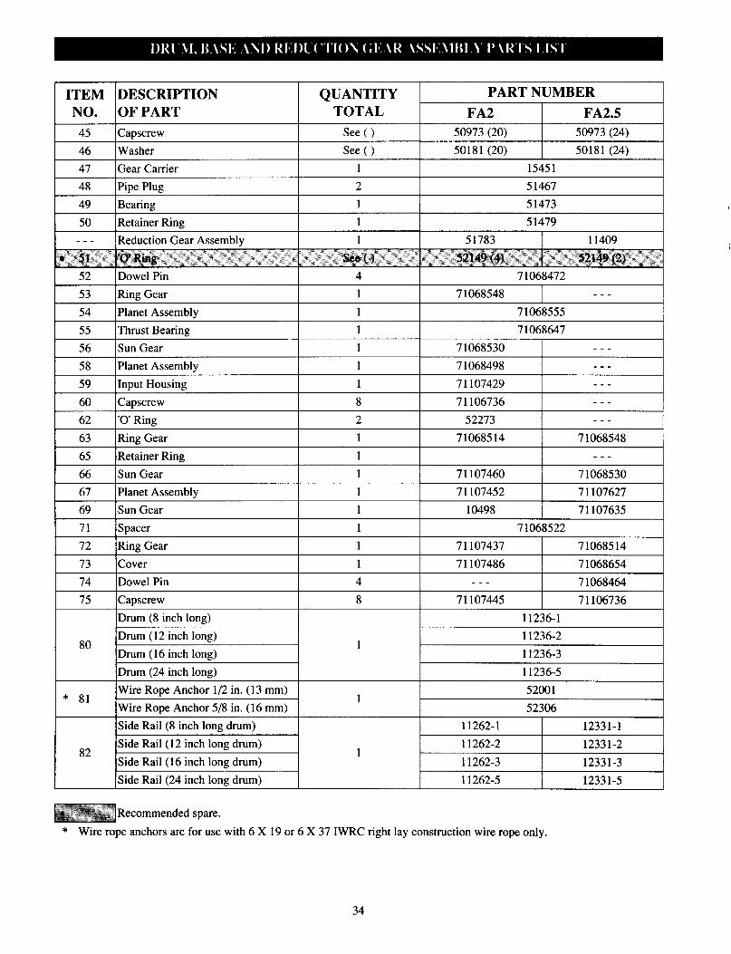
ITEM DESCRIPTION QUANTITY PART NUMBER
NO. OF PART TOTAL FA2 FA2.5
45 Capscrew 50973 (20) 50973 (24)
46 Washer See ( ) 50181 (20) 50181 (24)
47 Gear Carrier 1 15451
48 Pipe Plug 2 51467
49 Bearing 1 51473
50 Retainer Ring 1 51479
--- Reduction Gear Assembly 1 51783 11409
• 51 'O' Ring See ( ) 52149 (4) 52149 (2)
52 Dowel Pin 71068472
53 Ring Gear 1 7 1068548 ---
54 Planet Assembly 1 71068555
55 Thrust Bearing 1 71068647
56 Sun Gear I 71068530 ---
58 Planet Assembly 1 71068498 ---
59 Input Housing 1 71107429 ---
60 Canscrew 8 71106736 ---
62 - ‘0’ Ring 2 52273 ---
63 Ring Gear I 71068514 71068548
65 Retainer Ring 1 ---
66 Sun Gear 1 71107460 71068530
67 Planet Assembly 1 71107452 71107627
69 Sun Gear 1 10498 71107635
71 Spacer 1 71068522
72 Ring Gear 1 71107437 71068514
73 Cover 1 71107486 71068654
74 Dowel Pin 4 --- 7 1068464
75 Capscrew 8 71107445 71106736
80
Drum (8 inch long)
Drum (12 inch long)
Drum (16 inch long)
Drum (24 inch long)
11236-l
11236-2 1
11236-3
11236-5
* 81 Wire Rope Anchor l/2 in. (13 mm) 52001
1 Wire Rope Anchor 5/8 in. (16 mm) 52306
Side Rail (8 inch long drum) 11262-l 12331-1
Side Rail 82
(12 inch long drum) 11262-2 1
12331-2
Side Rail (16 inch long drum) 11262-3 12331-3 Side Rail (24 inch long drum) 11262-5 12331-5
Recommended spare.
* Wire rope anchors are for use with 6 X 19 or 6 X 37 IWRC right lay construction wire rope only.
34
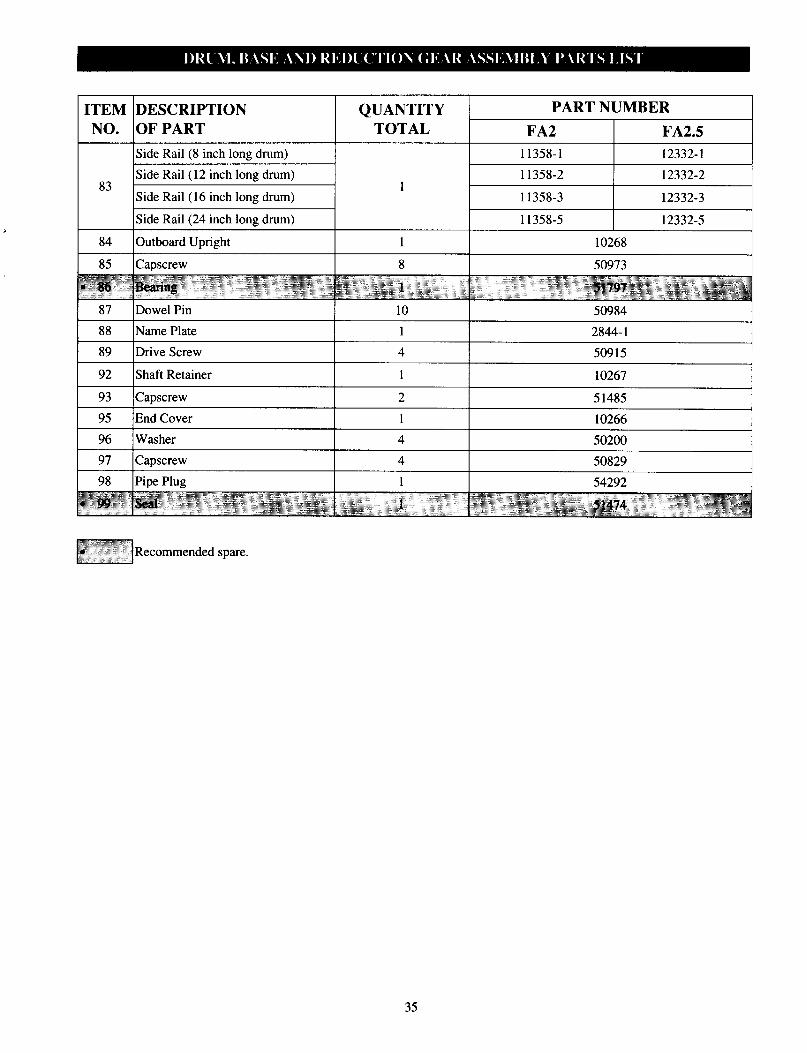
ITEM DESCRIPTION QUANTITY PART NUMBER NO. OF PART TOTAL FA2 FA2.5
Side Rail (8 inch long drum) 11358-1 12332-1
83 Side Rail (12 inch long drum)
1 11358-2 12332-2
Side Rail (16 inch long drum) 11358-3 12332-3
Side Rail (24 inch long drum) 11358-5 12323-5
84 Outboard Upright 1 10268
85 Capscrew 8 50973
• 86 Bearing 1 51797 87 Dowel Pin 10 50984
88 Name Plate 1 2844-1
89 Drive Screw 4 50915
92 Shaft Retainer 1 10267
93 Capscrew 2 51485
95 End Cover 1 10266
50200
4 50829 1 54292
1 51474
96 Washer
97 Capscrew 97 Pipe Plug
• 99 Seal
Recommended spare.
35

(Dwg. MHTPA0152)
36
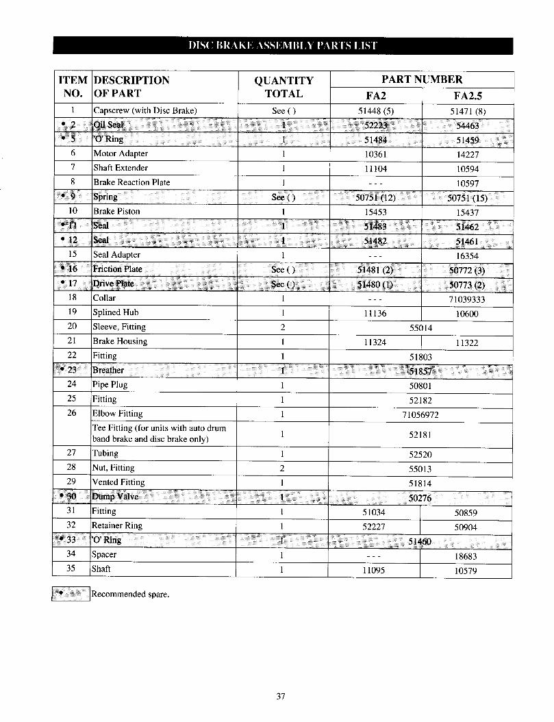
ITEM DESCRIPTION NO. OF PART
QUANTITY PART NUMBER
TOTAL FA2 FA2.5 1 Capscrew (with Disc Brake) See ( ) 51448(5) 51471 (8)
• 2 Oil Seal 1 52223 54463
• 5 'O' Ring 1 51484 51459 6 Motor Adapter 1 10361 14227 7 Shaft Extender 1 11104 10594 8 Brake Reaction Plate 1 --- 10597
• 9 Spring See ( ) 50751(12) 50751 (15)
10 Brake Piston 1 15453 15437
• 11 Seal 1 51483 51462
• 12 Seal 1 51482 51461
15 Seal Adapter 1 --- 16354 • 16 Friction Plate See ( ) 51481 (2) 50772 (3) • 17 Drive Plate See ( ) 51480 (1) 50773 (2)
18 Collar 1 --- 71039333 19 Splined Hub 1 1136 10600 20 Sleeve, Fitting 2 55014
21 Brake Housing 1 11324 11322 22 Fitting 1 51803 • 23 Breather 1 51857 24 Pipe Plug 1 50801
25 Fitting 1 52182
26 Elbow Fitting 1 71056972 Tee Fitting (for units with auto drum) band brake and disc brake only)
1 52181
27 Tubing 1 52520 28 Nut, Fitting 2 55013 29 Vented Fitting 1 51814
• 30 Dump Valve 1 50276 31 Fitting 1 51034 50859 32 Retainer Ring 1 52227 50904
• 33 'O' Ring 1 51460 34 Spacer 1 --- 18683 35 Shaft 1 11095 10579
Recommended spare.
37
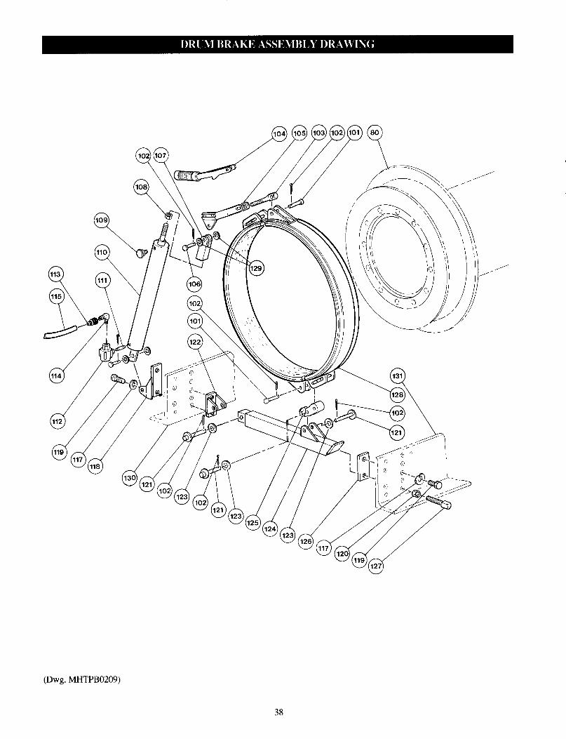
(Dwg. MHTPB0209)
38
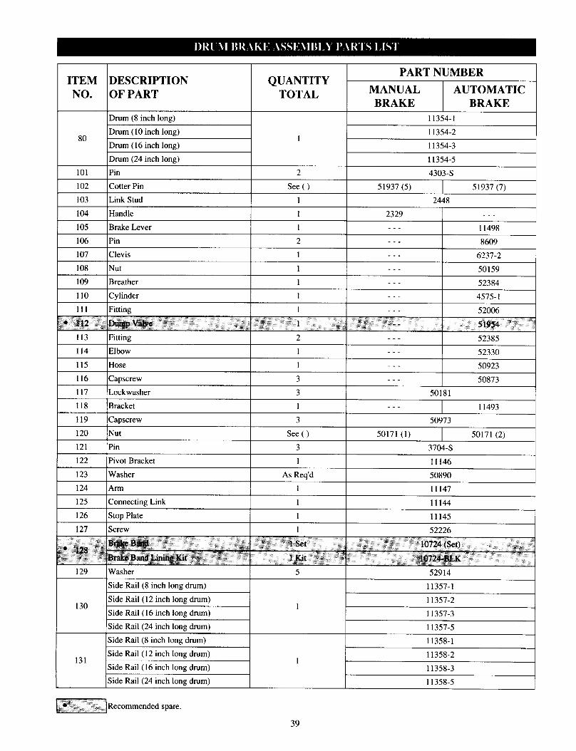
ITEM DESCRIPTION QUANTITY NO. OF PART TOTAL
80
101
102
Drum (8 inch long)
Drum (10 inch long)
Drum (16 inch long)
Drum (24 inch long)
Pin
Cotter Pin
11354-l
11354-2 1
11354-3
11354-5
2 4303-s
See ( ) 51937 (5) 5 1937 (7)
103 Link Stud 1 2448
104 Handle 1 2329 ___
105 Brake Lever 1 ___ 11498
106 Pin 2 --- 8609
107 Clevis 1 --_ 6277-2
108 Nut 1 --_ 50159
109 Breather 1 ___ 53384
110 Cylinder 1 ___ 4575-l
111 Fitting 1 ___ 52006
• 112 Dump Valve 1 --- 51954 113 Fitting 2 --- 52385 114 Elbow 1 --- 52330
115 Hose 1 ___ 50923
116 Capscrew 3 ___ 50873
117 Lockwasher 3 50181
118 Bracket 1 --- 11493
119 Capscrew 50973 120 Nut See ( ) 50171 (1) 50171 (2) 121 Pin 3 3704-S 122 Pivot Bracket 1 11146
123 Washer AS Req'd 50890 124 Arm 1 11147
125 Connecting Link Text 11144 126 Stop Plate Text 11145
127 Screw Text 52226
• 128 Brake Band 1 Set 10724 (Set) Brake Band Lining Kit 1 Kit 10724-BLK
129
130
131
Washer
Side Rail (8 inch long drum)
Side Rail (12 inch long drum)
Side Rail (16 inch long drum)
Side Rail (24 inch long drum)
Side Rail (8 inch long drum)
Side Rail (12 inch long drum)
Side Rail (16 inch long drum)
Side Rail (24 inch long drum)
5 52914
11357-I
11357-2 1
11357-3
11357-5
11358-I
11358-2 1
11358-3
11358-5
Recommended spare.
39

(Dwg. MHTPB0210)
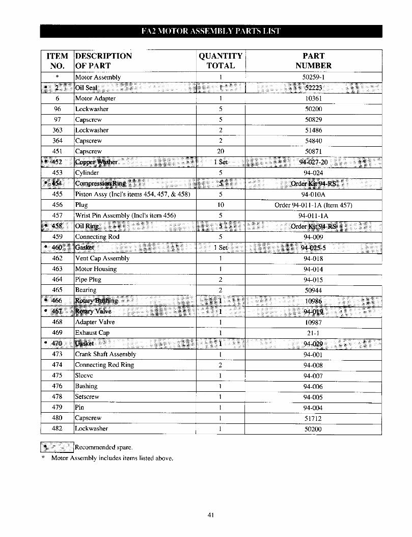
ITEM DESCRIPTION QUANTITY PART NO. OF PART TOTAL NUMBER
* Motor Assembly 1 50259-1
• 2 Oi1 Seal 1 52223
6 Motor Adapter 1 10361
96 Lockwasher 5 50200
97 Capscrew 5 50829
363 Lockwasher
364 Capscrew
2 51486
2 54840
451 Capscrew 20 50871
• 452 Copper Washer 1 Set 94-027-20
453 Cylinder 5 94-024
• 454 Compression Ring 5 Order Kit 94-RS
455 Piston Assy (Incl’s items 454,457, & 458) 5 94-0l0A
456 Plug 10 Order 94-11-1A (Item 457)
457 Wrist Pin Assembly (Incl’s item 456) 5 94-011-1A
• 458 Oil Ring 5 Order Kit 94-RS 459 Connecting Rod 5 94-009 • 460 Gasket 1 Set 94-025-5
Vent Cap Assembly Text 94-018
463 Motor Housing 1 94-014
464 Pipe Plug 2 94-015
465 Bearing 2 50944 • 466 Rotary Bushing 1 10986 • 467 Rotary Valve 1 94-019
468 Adapter Valve 1 10987
469 Exhaust Cap 1 21-1
• 470 Gasket 1 94-029 473 Crank Shaft Assembly 1 94-001
474 Connecting Rod Ring 2 94-008 475 Sleeve 1 94-007
476 Bushing 1 94-006
478 Setscrew 1 94-005
479 Pin 1 94-004
480 Capscrew 1 51712
482 Lockwasher 1 50200
Recommended spare.
* Motor Assembly includes items listed above.
41
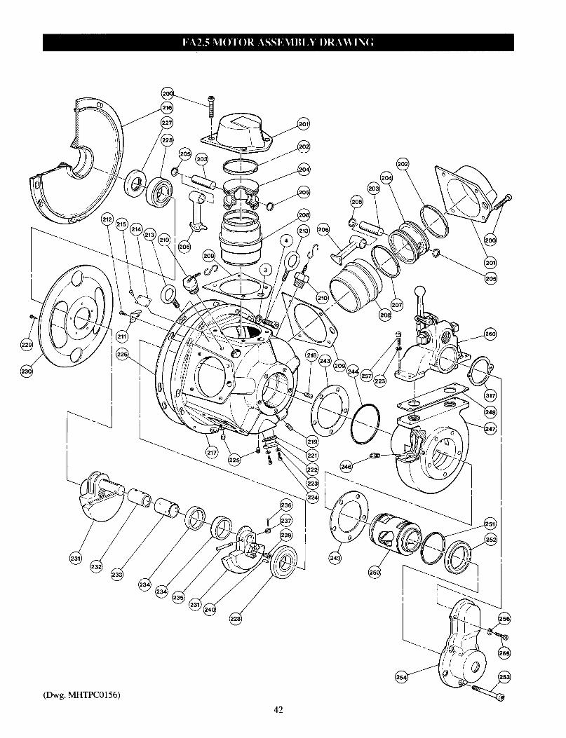
(Dwg. MHTPC0156)
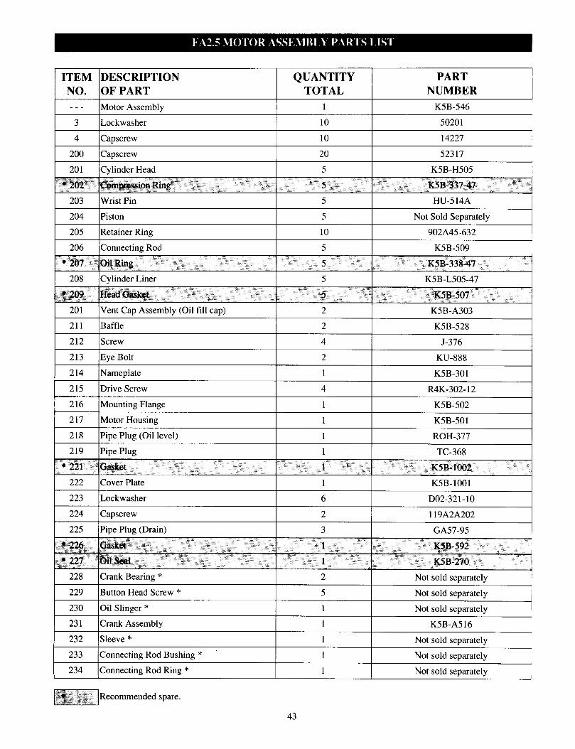
ITEM DESCRIPTION QUANTITY PART NO. OF PART TOTAL NUMBER
--- Motor Assembly 1 K5B-546
3 Lockwasher Text Text
4 Capscrew 10 14227
200 Capscrew 20 52317
201 Cylinder Head 5 K5B-H505
• 202 Compression Ring 5 K5B-337-47
203 Wrist Pin 5 HU-514A
204 Piston 5 Not Sold Separately
205 Retainer Ring 10 902A45-632
206 Connecting Rod 5 K5B-509
• 207 Oil Ring 5 K5B-338-47 208 Cylinder Liner 5 K5B-L505-47
• 209 Head Gasket 5 K5B-507
201 Vent Cap Assembly (Oil fill cap) 2 K5B-A303 211 Baffle 2 K5B-528
212 Screw 4 J-376
213 Eye Bolt 2 KU-888
214 Nameplate 1 K5B-301
215 Drive Screw 4 R4K-302-12
216 Mounting Flange 1 K5B-502
217 Motor Housing 1 K5B-501
218 Pipe Plug (Oil level) 1 ROH-377
219 Pipe Plug 1 TC-368
. • 221 Gasket 1 K5B-1002
222 Cover Plate 1 K5B-1001
223 Lockwasher 6 D02-321-10
224 Capscrew 2 119A2A202
225 Pipe Plug (Drain) 3 GA57-95
• 226 Gasket 1 K5B-592 • 227 Oil Seal 1 K5B-270
228 Crank Bearing * 2 Not sold separately
229 Button Head Screw * 5 Not sold separately
230 Oil Slinger * 1 Not sold separately
231 Crank Assembly 1 K5B-A516
232 Sleeve * 1 Not sold separately
233 Connecting Rod Bushing * 1 Not sold separately
234 Connecting Rod Ring * 1 Not sold separately
Recommended spare.
43
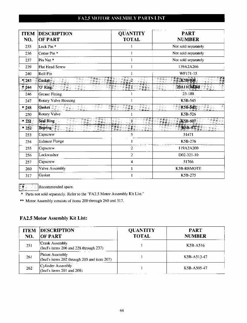
ITEM DESCRIPTION NO. OF PART
QUANTITY PART TOTAL NUMBER
235 Lock Pin * 1 Not sold separately
236 Cotter Pin * 1 Not sold separately
237 Pin Nut * 1 Not sold separately
239 Flat Head Screw 1 139A2A266
240 Roll Pin 1 WF171-15
• 243 Gasket 2 K5B-928
• 244 ‘0’ Ring 1 20AllCM248
246 Grease Fitting 1 23-188
247 Rotary Valve Housing 1 K5B-545 • 248 Gasket 1 K5B-547 250 Rotary Valve 1 K5B-526
• 251 Seal Ring 1 K5B-607
• 252 Bearing 1 K5B-97 253 Capscrew 5 51471
254 Exhaust Flange 1 K5B-276
255 Capscrew 2 119A2A200
256 Lockwasher 2 D02-321-10
257 Capscrew 4 51766
260 Valve Assembly 1 K5B-REMOTE
317 Gasket 1 K5B-275
Recommended spare.
* Parts not sold separately. Refer to the “FA2.5 Motor Assembly Kit List.”
** Motor Assembly consists of items 200 through 260 and 317.
FA2.5 Motor Assembly Kit List:
ITEM DESCRIPTION QUANTITY PART NO. OF PART TOTAL NUMBER
231 Crank Assembly (Incl’s items 206 and 228 through 237)
1 K5B-A516
261 Piston Assembly (Incl’s items 202 through 205 and item 207)
1 K5B-A513-47
262 Cylinder Assembly (Incl’s items 201 and 208)
1 K5B-A505-47
44

(Dwg. MHTPA0203)
QTY TOTAL
Valve Assembly 260 (Incl’s items 420 1
through 444)
420 Handle
• 421 Ball 2
• 422 Spring 2
423 Pin 2 424 Washer 2
425 Pin 1
426 Handle Bracket 1
428 Pin 2
249 Pin 1
430 Screw 2
PART ITEM DESCRIPTION QTY PART NUMBER NO. OFPART TOTAL NUMBER
431 Capscrew 2 5 1025
51710 432 Sleeve 2 71077473 433 Pipe Plug 1 51599
11882 434 Pipe Plug 1 11886 71077119 436 Poppet Valve 1 11879
11862 438 Housing 1 *
71077101 439 Grease Fitting 1 50192 52914 • 440 Valve Bushing 1 11883
11860 • 441 Valve 1 11865
118778 442 Exhaust Cover 1 11881
443 Lockwasher 4 51801
52161 444 Capscrew 4 51770 11861 444 Capscrew 4 51770
11884
Recommended spare.
* Not sold separately. Order Valve Assembly 5 17 10 (item 260).
45
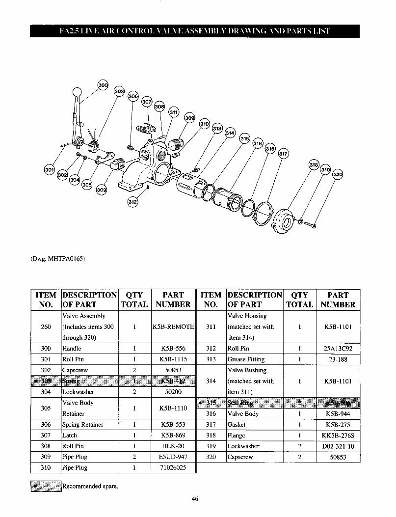
(Dwg. MHTPA0165)
QTY TOTAL
PART NUMBER
ITEM NO.
DESCRIPTION OF PART
QTY PART
TOTAL NUMBER ITEM DESCRIPTION
NO. OF PART
Valve Assembly
260 (Includes items 300
through 320)
300 Handle
Valve Housing
(matched set with
item 3 14)
K5B-REMOTE 311 1
1
1 2
1
2
K5B-1101
K5B-556 312 Roll Pin 1 25A13C92
301 Roll Pin
302 Capscrew
• 303 Spring 304 Lockwasher
313
314
• 315
316
K5B-1115
50853
K5B-412
Grease Fitting
Valve Bushing
(matched set with
item 311)
Seal Ring
1 23-188
1 K5B-1101
2 K5B-606 50200
305 Valve Body
Retainer K5B-1110 1
1
1
1
2 1
Valve Body 1 K5B-944
1 K5B-275
1 KK5B-276S
2 D02-321-10
306 Spring Retainer
307 Latch
Gasket K5B-553
K5B-869
317
318 Flange
308 Roll Pin
309 Pipe Plug 310 Pipe Plug
HLK-20 Lockwasher
E5UD-947 320 Capscrew 2 50853
71026025
Recommended spare.
46
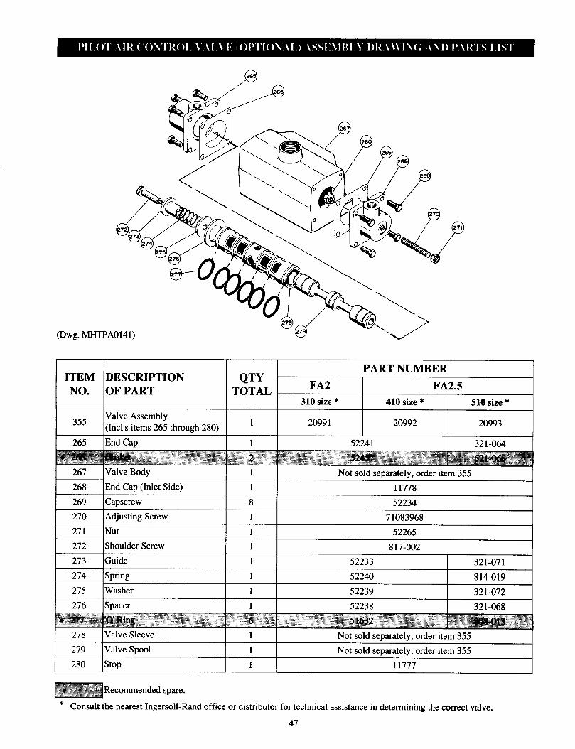
MHTPA0141)
PART NUMBER ITEM DESCRIPTION QTY
NO. OF PART TOTAL FA2 FA2.5
310 size * 410 size * 510 size *
355 Valve (Incl’s items 265 through 280) 1 2099 1 20992 20993
265 End Cap 1 52241 321-064
• 266 Gasket 2 52457 521-066 267 Valve Body 1 Not sold separately, order item 355 268 End Cap (Inlet Side) 1 11778
269 Capscrew 8 52234
270 Adjusting Screw 1 71083968
271 Nut 1 52265
272 Shoulder Screw 1 817-002 273 Guide 1 52233 321-071 274 Spring 1 52240 814-019 275 Washer 1 52239 321-072 276 Spacer 1 52238 321-068
• 277 'O' Ring 6 51632 808-013 278 Valve sleeve 1 Not sold separately, order item 355
279 Valve Spool 1 Not sold separately, order item 355 280 Stop 1 11777
Recommended spare.
* Consult the nearest Ingersoll-Rand office or distributor for technical assistance in determining the correct valve.
47
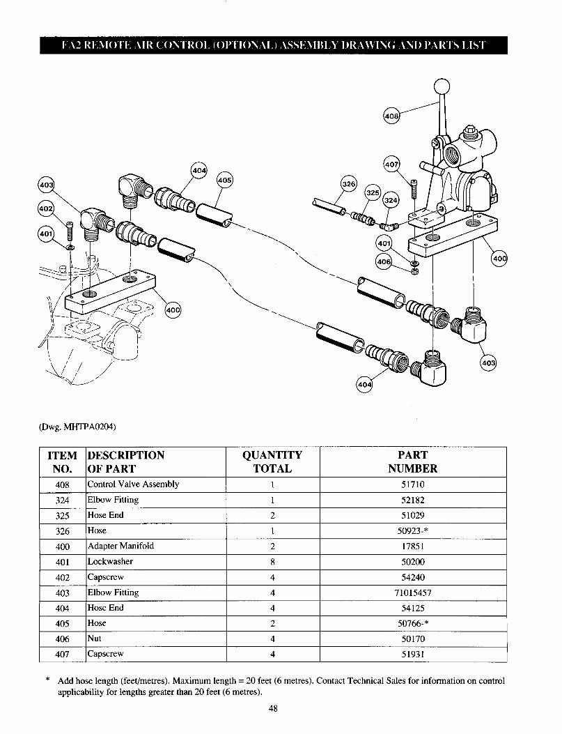
(Dwg. MHTPA0204)
ITEM DESCRIPTION NO. OF PART
QUANTITY PART TOTAL NUMBER
408 Control Valve Assembly 1 51710
324 Elbow Fitting 1 52182
325 Hose End
326 Hose
2 51029
50923-*
400 Adapter Manifold 2 17851
401 Lockwasher 8 50200
402 Capscrew 54240
403 Elbow Fitting 4 71015457
404 Hose End 4 54125
405 Hose 2 50766-*
406 Nut 4 50170
407 Capscrew 51931
* Add hose length (feet/metres). Maximum length = 20 feet (6 metres). Contact Technical Sales for information on control applicability for lengths greater than 20 feet (6 metres).
48
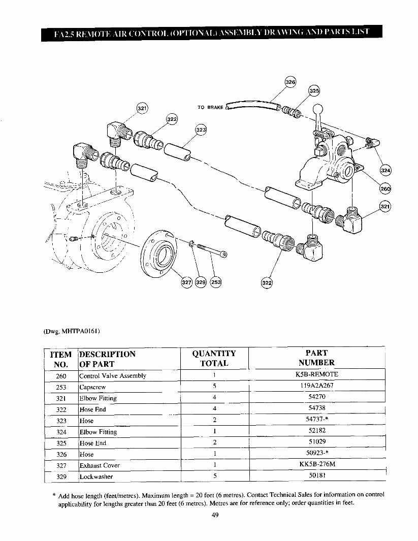
(Dwg. MHTPA0161)
ITEM DESCRIPTION QUANTITY PART
NO. OF PART TOTAL NUMBER
260 Control Valve Assembly 1 K5B-REMOTE 253 Capscrew 5 119A2A267
321 Elbow Fitting 4 54270
322 Hose End 4 54738
323 Hose 2 54737-*
324 Elbow Fitting 1 52182
325 Hose End 2 51029
326 Hose 1 50923-*
327 Exhaust Cover 1 KK5B-276M
329 Lockwasher 5 50181
* Add hose length (feet/metres). Maximum length = 20 feet (6 metres). Contact Technical Sales for information on control applicability for lengths greater than 20 feet (6 metres). Metres are for reference only; order quantities in feet.
49

Valve Mount
FA2.5 Winch
(Dwg. MHTPA0211)
50
(Dwg. MHTPA0167)
Valve Mount
FA2 Winch

Remote Pilot Pendant Throttle Control
DESCRIPTION QTY PART NUMBER
OF PART TOTAL 10 ft (3 m) 20 ft (6 m) 30 ft (9 m) 40ft (12 m) 324 Elbow Fitting 4 52182
325 Hose End Fitting See ( ) 5 1029 (6) 51029 (10) 51029 (14)
333 Capscrew 4 5468 1
334 Lockwasher 4 50893
335 Manifold 1 13881
336 Lockwasher (FA2) 2
Lockwasher (FA2.5) 4 51486
337 Capscrew 4 50829
338 Nipple Fitting 3 54274
339 Pipe Tee Fitting 2 54678
340 Adapter Fitting 2 51814
1 17073-6
1 50277
1 17073-10 See ( ) 50923-(132) 50923-(242) 50923-(233) 50923-(245) As Req'd --- 71048284
341 Hose Assembly
• 343 Shuttle Valve
344 Hose Assembly (Brake)
345 Hose 346 Adapter Fitting
347 Exhaust Valve* As Req’d - - - 20417
348 Adapter Fitting
349 Hose
350 Hose
352 Control Pendant
As Req’d
See ( )
See ( )
1
7 1048268
___ 50923-(6) 50923-(123) 50923-(6)
50923-(123) 50923-(252) 50923-(372) 50923-(492)
MLK-A269A
353 Hose See ( ) ___ 50923-(6) 50923-(135) 50923-(6)
354 Hose See ( ) 50923-(120) 50923-(230) 50923-(233)
Valve 355 Assembly
(FA2) 2099 1 1
Valve Assembly (FA2.5) 20992
356 Hose **
361 Rotary Valve
See( ) --- --- --- 50923-(233)
1 9148
362 Cover 1 11543
364 Capscrew 2 54840
365 Lockwasher 4 51013
366 Capscrew 4 52906
Recommended spare.
* Must be installed at 20 foot (6 metre) intervals. Part number 20417 includes items 346 and 348.
** Not shown. Install between exhaust valves. ( ) = Quantity in inches,
Remote Pilot Lever Throttle Valve Associated Components Note: Requires item #‘s 325,333 through 344 (Reference “Remote Pilot Pendant Throttle Control”) plus the following parts.
ITEM DESCRIPTION QTY PART NO. OF PART TOTAL NUMBER 345 Hose See ( ) 50923-(233)
346 Adapter Fitting 2 71048284
347 Exhaust Valve ** 2 71047898
348 Adapter Fitting 1 71048268
349 Hose See ( ) 50923-(135)
* Part numbers and quantities are for a 30 foot (9 metre) hose assembly. ( ) = Quantity in inches.
51

FA2.5 Muffler with Remote Actuated Pilot Control Valve (Old Style)
FA2.5 Muffler with Live Air Throttle Valve
FA2.5 Mufflers with Remote Actuated Pilot Control Valve (New Style)
FA2 Mufflers with Remote Actuated Pilot Control Valve
(Dwg MHTPA0515)
52
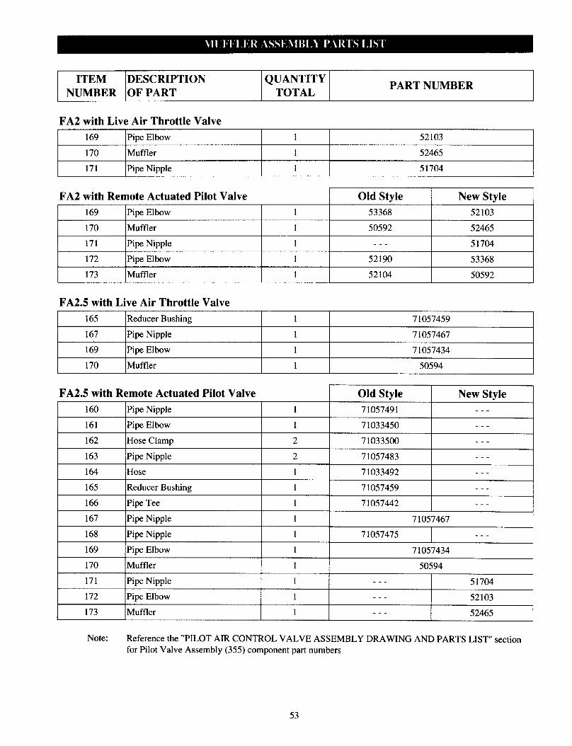
ITEM DESCRIPTION QUANTITY
NUMBER OF PART TOTAL PART NUMBER
FA2 with Live Air Throttle Valve
169 Pipe Elbow 1 52103
I 170 Muffler 1 52465 I 171 Pipe Nipple 1 51704
FA2 with Remote Actuated Pilot Valve
169 Pipe Elbow
170 Muffler
171 Pipe Nipple
172 Pipe Elbow
173 Muffler
FA2.5 with Live Air Throttle Valve
Old Style New Style
53368 52103
50592 52465
___ 51704
52190 53368
52104 50592
165 Reducer Bushing 1 71057459
167 Pipe Nipple 1 71057467
169 Pipe Elbow 1 71057434
170 Muffler 1 50594
FA2.5 with Remote Actuated Pilot Valve Old Style New Style 160 Pipe Nipple 1 71057491 --- 161 Pipe Elbow 1 71033450 ---
162 Hose Clamp 2 71033500 --- 163 Pipe Nipple 2 71057483 --- 164 Hose 1 71033492 --- 165 Reducer Bushing 1 71057459 --- 166 Pipe Tee 1 71057442 ---
167 Pipe Nipple 1 71057467
168 Pipe Nipple 1 71057475 ---
169 Pipe Elbow 1 71057434 170 Muffler 1 50594 171 Pipe Nipple 1 --- 51704 172 Pipe Elbow 1 --- 52103 173 Muffler 1 --- 52465
Note: Reference the “PILOT AIR CONTROL VALVE ASSEMBLY DRAWING AND PARTS LIST” section for Pilot Valve Assembly (355) component part numbers
53
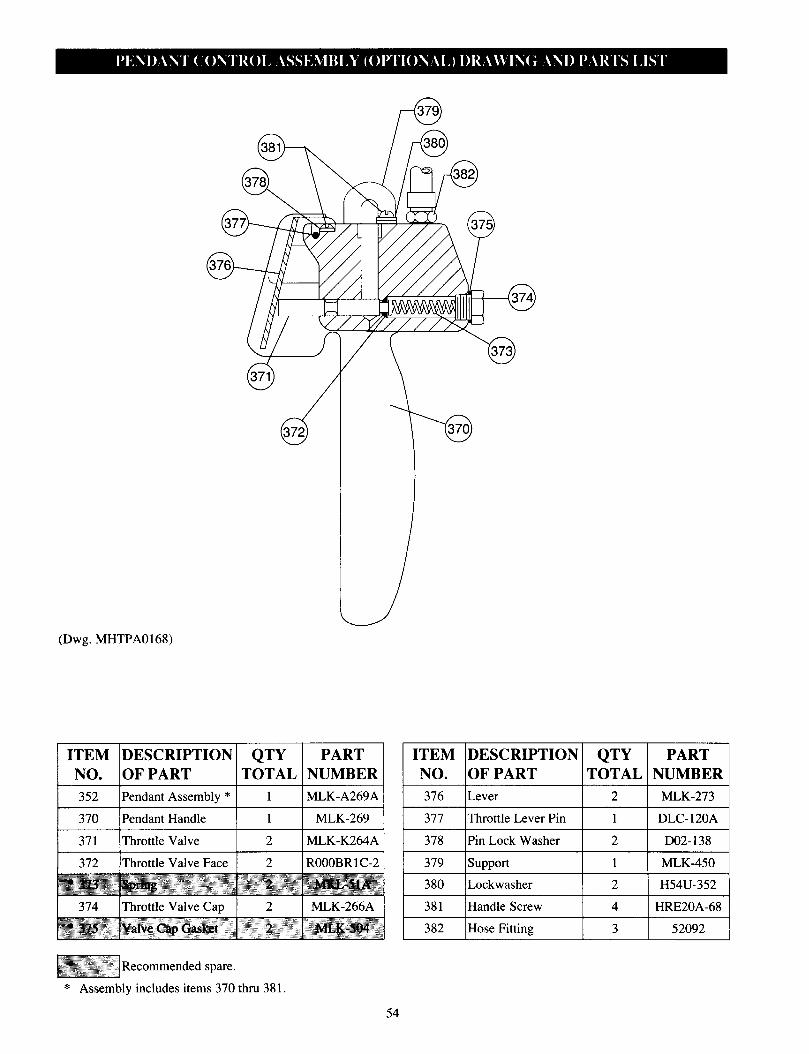
(Dwg. MHTPA0168)
ITEM DESCRIPTION QTY PART
NO. OF PART TOTAL NUMBER
352 Pendant Assembly * 1 MLK-A269A
ITEM DESCRIPTION QTY PART NO. OF PART TOTAL NUMBER
376 Lever 2 MLK-273
370 Pendant Handle 1 MLK-269 377 Throttle Lever Pin 1 DLC-120A
371 Throttle Valve 2 MLK-K264A 378 Pin Lock Washer 2 D02-138
372 Throttle Valve Face 2 R000BR1C-2 379 support 1 MLK-450
• 373 Spring 2 MKL-51A 380 Lockwasher 2 H54U-352
374 Throttle Valve Cap 2 MLK-266A 381 Handle Screw 4 HRE20A-68
• 375 Valve Cap Gasket 2 MLK-504 382 Hose Fitting 3 52092 ,
Recommended spare.
* Assembly includes items 370 thru 38 1.
54
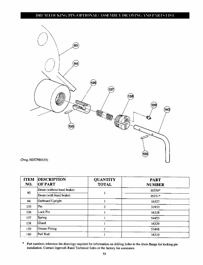
(Dwg. h4HTPB0l55)
ITEM DESCRIPTION QUANTITY NO. OF PART TOTAL NUMBER
80 Drum (without band brake) Drum (with band brake)
1 16330*
16331* 84 Outboard Upright 1 16327 135 Pin 2 51933
136 Lock Pin 1 16328 137 Spring 1 54453 138 Gland 1 16329 139 Grease Fitting 1 53498 140 Pull Rod 1 16310
PART
* Part numbers reference the drawings required for information on drilling holes in the drum flange for locking pin
installation. Contact Ingersoll-Rand Technical Sales or the factory for assistance.
55
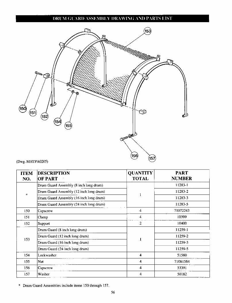
(Dwg. MHTPA0205)
ITEM DESCRIPTION NO. OF PART
Drum Guard Assembly (8 inch long drum)
Drum Guard Assembly (12 inch long drum) *
Drum Guard Assembly (16 inch long drum)
Drum Guard Assembly (24 inch long drum)
QUANTITY TOTAL
1
PART NUMBER
11283-l
11283-2
11283-3
11283-5
150 Capscrew 4 71072243 I 151 Clamp 4 10399
152 support 2 10400
153
154
Drum Guard (8 inch long drum)
Drum Guard (12 inch long drum)
Drum Guard (16 inch long drum)
Drum Guard (24 inch long drum)
Lockwasher
11259-l
11259-2 1
11259-3
11259-5
4 51580
155 Nut 4 71061584 I
156 Capscrew 4 53391
157 Washer 4 50182
* Drum Guard Assemblies include items 150 through 157.
56
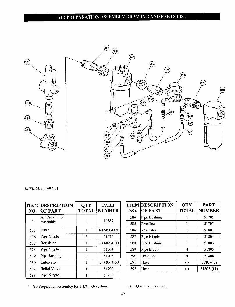
(Dwg. MHTPA0223)
* Air Preperation Assembly for 1 -l/4 inch system.
ITEM DESCRIPTION QTY PART ITEM DESCRIPTION NO. OF PART TOTAL NUMBER NO. OF PART
* Air Preparation 1 10389 584 /Pipe Bushing 1 51705
Assembly 585 Pipe Tee 1 51707
575 Filter 1 F42-0A-000 586 Regulator 1 51802
576 Pipe Nipple 2 51670 587 Pipe Nipple 1 51804
577 Regulator 1 R30-0A-G00 588 Pipe Bushing
578 Pipe Nipple 1 51704 589 Pipe Elbow
I 51803
4 51805
579 Pipe Bushing 2 51706 590 Hose End 4 51806
580 Lubricator 1 L40-0A-G00 591 Hose () 51807-(8)
( ) 51807-(11) 582 Relief Valve 1 51702 592 Hose
583 Pipe Nipple 1 50933
( ) = Quantity in inches.
57
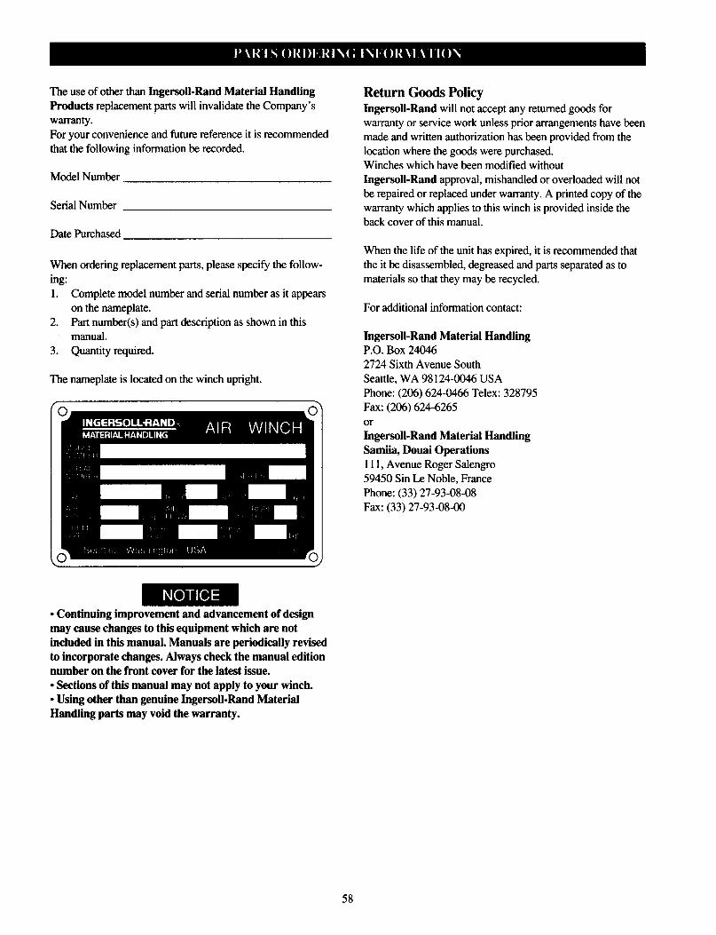
The use of other than Ingersoll-Rand Material Handling Products replacement parts will invalidate the Company’s warranty.
For your convenience and future reference it is recommended that the following information be recorded.
Model Number
Serial Number
Date Purchased
When ordering replacement parts, please specify the follow-
ing: 1. Complete model number and serial number as it appears
on the nameplate. 2. Part number(s) and part description as shown in this
manual. 3. Quantity required.
The nameplate is located on the winch upright.
l Continuing improvement and advancement of design may cause changes to this equipment which are not included in this manual. Manuals are periodically revised to incorporate changes. Always check the manual edition number on the front cover for the latest issue. l Sections of this manual may not apply to your winch. l Using other than genuine Ingersoll-Rand Material Handling parts may void the warranty.
Return Goods Policy Ingersoll-Rand will not accept any returned goods for warranty or service work unless prior arrangements have been made and written authorization has been provided from the location where the goods were purchased. Winches which have been modified without Ingersoll-Rand approval, mishandled or overloaded will not be repaired or replaced under warranty. A printed copy of the warranty which applies to this winch is provided inside the back cover of this manual.
When the life of the unit has expired, it is recommended that the it be disassembled, degreased and parts separated as to materials so that they may be recycled.
For additional information contact:
Ingersoll-Rand Material Handling P.O. Box 24046 2724 Sixth Avenue South
Seattle, WA 98 124-0046 USA Phone: (206) 624-0466 Telex: 328795
Fax: (206) 624-6265
or Ingersoll-Rand Material Handling Samiia, Douai Operations 111, Avenue Roger Salengro 59450 Sin Le Noble, France
Phone: (33) 27-93-08-08 Fax: (33) 27-93-08-00
58
HOIST AND WINCH LIMITED WARRANTY
Ingersoll-Rand Company (I-R) warrants to the original user its Hoists and Winches (Products) to
be free of defects in material and workmanship for a period of one year from the date of purchase. I-R will repair, without cost, any Product found to
be defective, including parts and labor charges, or at its option, will replace such Products or refund
the purchase price less a reasonable allowance for
depreciation, in exchange for the Product. Repairs or replacements are warranted for the remainder of the original warranty period.
If any Product proves defective within its original
one year warranty period, it should be returned to any Authorized Hoist and Winch Service Dis- tributor, transportation prepaid with proof of purchase or warranty card.
This warranty does not apply to Products which I-R has determined to have been misused or abused, improperly maintained by the user, or where the malfunction or defect can be attributed
to the use of non-genuine I-R parts.
I-R makes no other warranty, and all implied warranties including any warranty of merchantability or fitness for a particular purpose are limited to the duration of the expressed warranty period as set forth above.
I-R’s maximum liability is limited to the purchase price of the Product and in no event shall I-R be liable for any consequential, indirect, incidental, or special damages of any nature rising from the sale or use of the Product, whether based on contract, tort, or otherwise.
Note: Some states do not allow limitations on incidental or consequential damages or how long an implied warranty lasts so that the above
limitations may not apply to you.
This warranty gives you specific legal rights and you may also have other rights which may vary from state to state.
IMPORTANT NOTICE
It is our policy to promote safe delivery of all orders.
This shipment has been thoroughly checked, packed and inspected before leaving our plant and
receipt for it in good condition has been received from the carrier. Any loss or damage which occurs to this shipment while enroute is not due to any action or conduct of the manufacturer.
Visible Loss or Damage If any of the goods called for on the bill of lading
or express receipt are damaged or the quantity is short, do not accept them until the freight or express agent makes an appropriate notation on your freight bill or express receipt.
Concealed Loss or Damage When a shipment has been delivered to you in apparent good condition, but upon opening the
crate or container, loss or damage has taken place while in transit, notify the carrier’s agent immedi- ately.
Damage Claims You must file claims for damage with the carrier. It is the transportation company’s responsibility to reimburse you for repair or replacement of goods damaged in shipment. Claims for loss or damage in shipment must not be deducted from the Ingersoll-Rand invoice, nor should payment of
Ingersoll-Rand invoice be withheld awaiting adjustment of such claims as the carrier guarantees
safe delivery.
You may return products damaged in shipment to
us for repair, which services will be for your account and form your basis for claim against the carrier.
59
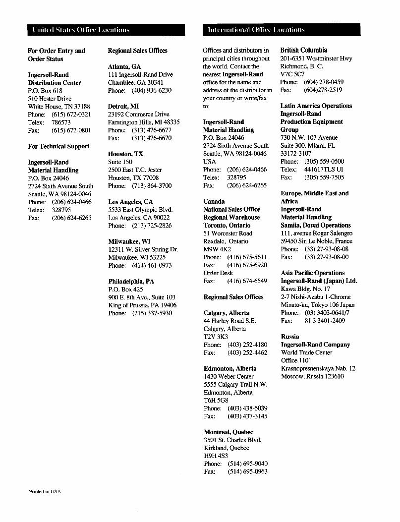
For Order Entry and Order Status
Ingersoll-Rand Distribution Center P.O. Box 618 5 10 Hester Drive White House, TN 37 188
Phone: (615) 672-0321 Telex: 786573
Fax: (615) 672-0801
For Technical Support
Ingersoll-Rand Material Handling P.O. Box 24046 2724 Sixth Avenue South
Seattle, WA 98 124-0046 Phone: (206) 624-0466 Telex: 328795
Fax: (206) 624-6265
Regional Sales Offices
Atlanta, GA 111 Ingersoll-Rand Drive
Chamblee, GA 30341 Phone: (404) 936-6230
Detroit, MI 23 192 Commerce Drive Farmington Hills, MI 48335
Phone: (3 13) 476-6677 Fax: (313) 476-6670
Houston, TX Suite 150 2500 East T.C. Jester
Houston, TX 77008 Phone: (7 13) 864-3700
Los Angeles, CA 5533 East Olympic Blvd. Los Angeles, CA 90022 Phone: (2 13) 725-2826
Milwaukee, WI 123 11 W. Silver Spring Dr. Milwaukee, WI 53225 Phone: (414) 461-0973
Philadelphia, PA P.O. Box 425 900 E. 8th Ave., Suite 103 King of Prussia, PA 19406 Phone: (215) 337-5930
Offices and distributors in principal cities throughout the world. Contact the nearest Ingersoll-Rand office for the name and address of the distributor in
your country or write/fax to:
Ingersoll-Rand Material Handling P.O. Box 24046 2724 Sixth Avenue South
Seattle, WA 98 124-0046 USA Phone: (206) 624-0466
Telex: 328795 Fax: (206) 624-6265
Canada National Sales Office Regional Warehouse Toronto, Ontario 5 1 Worcester Road
Rexdale, Ontario M9W 4K2 Phone: (416) 675-5611 Fax: (416) 675-6920
Order Desk Fax: (416) 674-6549
Regional Sales Offices
Calgary, Alberta 44 Harley Road S.E.
Calgary, Alberta T2V 3K3
Phone: (403) 252-4 180 Fax: (403) 252-4462
Edmonton, Alberta 1430 Weber Center 5555 Calgary Trail N.W.
Edmonton, Alberta T6H 5G8 Phone: (403) 438-5039
Fax: (403) 437-3 145
Montreal, Quebec 3501 St. Charles Blvd. Kirkland, Quebec H9H 4S3 Phone: (5 14) 6959040 Fax: (5 14) 695-0963
British Columbia 201-635 1 Westminster Hwy Richmond, B. C. V7C 5C7 Phone: (604) 278-0459
Fax: (604)278-25 19
Latin America Operations Ingersoll-Rand Production Equipment Group 730 N.W. 107 Avenue
Suite 300, Miami, FL 33172-3107 Phone: (305) 559-0500 Telex: 441617TLS UI
Fax: (305) 559-7505
Europe, Middle East and Africa Ingersoll-Rand Material Handling Samiia, Douai Operations 111, avenue Roger Salengro
59450 Sin Le Noble, France Phone: (33) 27-93-08-08 Fax: (33) 27-93-08-w
Asia Pacific Operations Ingersoll-Rand (Japan) Ltd. Kawa Bldg. No. 17 2-7 Nishi-Azabu l-Chrome Minato-ku, Tokyo 106 Japan
Phone: (03) 3403-0641/7 Fax: 813 3401-2409
Russia Ingersoll-Rand Company World Trade Center Oftice 1101 Krasnopresnenskaya Nab. 12 Moscow, Russia 123610
Printed in USA