models 17700/17701/17703 recovery/recycling/recharging ... · models 17700/17701/17703...
TRANSCRIPT

○ ○ ○ ○ ○ ○ ○ ○ ○ ○ ○ ○ ○ ○ ○ ○ ○ ○ ○ ○ ○ ○ ○ ○ ○ ○ ○ ○ ○ ○ ○ ○ ○ ○ ○ ○ ○ ○ ○ ○ ○ ○ ○ ○ ○ ○ ○ ○ ○ ○ ○ ○ ○ ○ ○ ○ ○ ○ ○ ○ ○ ○ ○ ○ ○ ○ ○ ○ ○ ○ ○ ○ ○ ○ ○ ○ ○ ○
Models 17700/17701/17703Recovery/Recycling/Recharging UnitFor R-12 Only
ServiceManual
Theory of Operation and Safety Precautions ........................ 2Component Descriptions ........................................................ 3Plumbing Diagram ................................................................. 8Pictorial Views ...................................................................... 10Wiring Diagram .................................................................... 12Component Specifications .................................................... 13Tubing Schematic ................................................................. 21Compressor Specifications and Service ............................... 22Troubleshooting .................................................................... 23RA19064 Replacement Main Board ..................................... 32RA19008 Replacement Scale ................................................ 34Diagnostic Procedures .......................................................... 36Function Test Guide ............................................................. 37Labor Rates ........................................................................... 38

2
ORIGINAL Models 17700/17701/17703 Service Manual
Theory of Operation and Safety Precautions
The 17700 Series recovery, recycle, evacuationand recharging units are designed to be used forR-12 type refrigerant only. These units are ULapproved and meet SAE J1991 standards.
These units began production in May of 1991 andwere superseded to the 17700A in January of1994. The model, serial number and manufactur-ing date code can be found on a white tag locatedon the back of the unit above the tank.
DEPRESSURIZING THE UNIT
1. Close both liquid and vapor valves on the50-lb. recovery tank.
2. Disconnect all hoses from the 50-lb. recoverytank.
3. Disconnect the red high side and blue low sidehoses from a hand-held manifold gauge set.
4. Connect the blue (36"-48") liquid hose to thelow side (blue handle) and the red (36") vaporhose to the high side (red handle) of a hand-held manifold gauge set.
5. Connect the yellow hose (usually connected tothe center port) of the hand-held manifoldgauge set to the intake of your 17650recovery unit.
6. Open both manifold valves on the hand-heldmanifold gauge set.
7. Plug in your 17650 recovery unit and pressthe Recovery Start button.
8. When the recovery light turns off (on the17650), wait ten (10) minutes and watch thehand-held manifold gauges for a rise inpressure above zero. Repeat Steps 7 and 8until positive pressure does not develop on thehand-held manifold gauge set.
9. Disconnect the blue (36"-48") liquid and red(36") vapor hoses from the hand-held mani-fold gauge set.
10. Connect the yellow (36") air purge hose andthe red (96") high side hose to the hand-heldmanifold gauge set.
11. Open both the high and low side gauge valveson the face of the 17700.
12. Press the Recovery Start button on the 17650.
13. When the recovery light turns off (on the17650), wait ten (10) minutes and watch thehand-held manifold gauges for a rise inpressure above zero. Repeat Steps 12 and 13until positive pressure does not develop on thehand-held gauge set).
▲▲▲▲▲ WARNING!
Always wear safety goggles when working with refrigerants. Contactwith refrigerant can cause eye injury. Disconnect lines and hoses withextreme caution! Pressurized refrigerant may be present in lines andhoses. Always point lines and hoses away from you and anyonenearby.
Always unplug the station from the power source before removing anyof the shrouding or beginning any service work.
To order parts please call Robinair Customer Service at 1-419-485-5561.Or FAX your order to 1-419-485-4330.
All service related questions should be directed to the RobinairTechnical Assistance Line at 1-800-822-5561.
REVISED 12/1/94

3
Models 17700/17701/17703 Service Manual ORIGINAL
Component Descriptions
8. RA17328 Vacuum Sensor — This is a normallyclosed sensor, designed to open when a 17" inchvacuum rating (±2") is reached in the inletmanifold. Note that this switch has orange wiresattached to it.
9. RA18760 System Oil Separator — This compo-nent performs three functions. Internal heatcauses incoming saturated vapor to evaporate.This is important for two reasons: one, to besure no liquid enters the compressor and, two, sothe oil droplets contained in the incomingrefrigerant will drop out in the separator. Thethird function will be discussed later.
10. 40460 Oil Drain Valve — Allows the oil that hasbeen removed from the system to be drainedwhen the recovery process is complete. The oilremoved from the system should be replacedwith new oil during recharging. 18429 Replace-ment Valve StemNote: It is important that the oil drainprocedure is done after each recovery.
38. RA17419 Oil Drain Bottle — Used to measurethe amount of used oil recovered from the vehiclebeing serviced.
11. 34430 Filter Drier — Removes moisture, acidand oil from refrigerant being circulated throughit during recovery and recycling. 40084 Replace-ment Hose Gasket
12. RA17434/RA17411 Compressor — Converts alow pressure/temperature entering gas into ahigh pressure/temperature discharge gas. Note:See Compressor Specifications and Service onpage 22.
13. RA19067 Compressor Oil Separator —Traps compressor oil that has migrated out withrefrigerant while passing through the compres-sor. Heat is added to the incoming refrigerant topromote vaporization through a series of coilsthat are wrapped around the outside of theseparator. The hot refrigerant contained in thecoils is then allowed to cool, promoting thecondensing of the refrigerant. The oil is stored inthe separator until the equalization solenoidloses power and allows the oil to be returned.
RECOVERY SIDE
1. RA17708 (2¼") RA19076 (2¾") RA17711 (2¾"220V metric) Low Side Gauge — Reads pres-sure and/or vacuum entering the low side hose.Note that the gauge will read pressure and/orvacuum in the low side hose with the low sidevalve closed. RA19256 (2¼") RA19257 (2¾")Replacement Gauge Lens.
2. RA19044 Low Side Manifold Valve — Allowsflow from the low side hose into the centermanifold tube (suction line strainer).RA19199 Manifold Stem Repair Kit
3. RA17709 (2¼") RA19075 (2¾) RA17712 (2¾"220V metric) High Side Gauge — Reads pres-sure entering the high side hose. Note that thegauge will read pressure in the high side hosewith the high side valve closed. RA19256 (2¼")RA19257 (2¾") Replacement Gauge Lens.
4. RA19044 High Side Manifold Valve — Allowsflow from the high side hose into the centermanifold tube (suction line strainer).RA19199 Manifold Stem Repair Kit
5. 115158 Suction Line Strainer — Filters therefrigerant coming from the high and low sidemanifold valves before entering into the inletcheck valve. Note that units produced afterOctober 1993 came equipped from the factorywith the strainer already installed.
6. RA17112 Inlet Check Valve — Allows flow in onedirection only, towards the recovery solenoid,and prevents refrigerant from escaping out ofthe inlet during shut down, evacuation orrecycling.
7. RA19006 Recovery Solenoid — This is anormally closed solenoid, designed to prevent theflow of refrigerant into the system oil separatorwhile the unit is off or in any mode other thanrecovery. Note that the control voltage is 120volts.RA19258 Solenoid Rebuild Kit
REVISED 12/1/94

4
ORIGINAL Models 17700/17701/17703 Service Manual
Component Descriptions
Note: Some units have automatic oil returncontrolled through the main board, when thecompressor runs continuously for ten (10)minutes the main board drops power to theequalization solenoid for 3 seconds and thenrepowers it.
14. RA17522 Equalization Solenoid — This is anormally open solenoid designed to allow oiltrapped in the compressor oil separator to beforced back into the suction side of the compres-sor when power is dropped to the solenoid.
15. RA17072 High Pressure Cut Out — This is anormally closed sensor designed to shut off theunit when discharge pressure reaches 350 psi.Note that this switch has three contacts on it,the outer two contacts (numbered 1 and 3 arenormally closed) have two solid red wiresconnected to them.
16. RA17112 Recovery Check Valve — Allows flowin one direction only. Prevents refrigerant in thetank from coming back into the unit duringshut down.
9. RA18760 System Oil Separator — At this point,high pressure/temperature vapor enters theseparator and passes through a condensing coilto give up heat to the incoming refrigerantsurrounding the coil, which causes the refriger-ant in the coils to cool and condense.
17. 110311 Air Purge Well — Houses the air purgedevice’s sensing bulb and allows refrigerant tocirculate around it.
18. RA17577 Moisture Indicator — References themoisture content of the refrigerant being re-cycled. Pale yellow indicates wet and light mintgreen indicates dry. During recovery the mois-ture indicator initially fills with liquid refriger-ant when recovery is started and drains out asthe system being recovered empties. Duringrecycling the moistureindicator is normally about half full of liquidrefrigerant and feels warm to the touch.
19. 68336 Red (36") Vapor Tank Hose — Deliversrefrigerant that is being recovered or recycled tothe vapor side of the 50-lb. recovery tank.18180 Replacement O-Rings40083 Standard Hose Gasket
RECYCLE SIDE
20. 17506 Recovery Tank — Stores refrigerant sothat it may be recycled at a later time. The tankhas two valves: one, a vapor valve which simplyis an open fitting to the tank and, two, a liquidvalve that has a draw tube extending to withintwo inches of the bottom of the tank.
21. 68248 Blue (48") Liquid Tank Hose — Allowsflow from the liquid side of the tank to thecharging solenoid and expansion valve.18180 Replacement O-Rings40083 Standard Hose Gasket
22. 113810 Liquid Line Strainer — Filters liquidcoming in from the blue liquid hose before goingto the charging solenoid or expansion valve.
23. RA17424 Automatic Expansion Valve — Con-verts incoming liquid refrigerant into a lowpressure saturated vapor. The calibration of theexpansion valve can be checked at the serviceport with a pressure gauge. The allowabletolerance of the valve is 30 to 40 psi whilerecycling. Note: Allow the unit to recycle ten(10) minutes with a minimum of 10 lbs. ofrefrigerant in the tank before checking oradjusting pressure.
24. RA19006 Recycling Solenoid — This is anormally closed solenoid designed to prevent theflow of refrigerant into the system oil separatorwhen the unit is not running in the recyclingmode. Note that the control voltage is 120 volts.RA19258 Solenoid Rebuild Kit
8. RA17328 Vacuum Sensor — This is a normallyclosed sensor designed to open when a 17" inchvacuum rating (±2") is reached in the inletmanifold. Note that this switch has orange wiresattached to it.
9. RA18760 System Oil Separator — This compo-nent performs two functions. Internal heatcauses incoming saturated vapor to evaporate.This is important so that no liquid enters thecompressor. The second function will be dis-cussed later.
REVISED 12/1/94

5
Models 17700/17701/17703 Service Manual ORIGINAL
Component Descriptions
10. 40460 Oil Drain Valve — Allows the oil that hasbeen removed from the system to be drainedwhen the recovery is complete. The oil removedfrom the system should be replaced with new oilduring recharging.18429 Replacement Valve StemNote: It is important that the oil drain proce-dure is done after each recovery.
38. RA17419 Oil Drain Bottle — Used to measurethe amount of used oil recovered from the vehiclebeing serviced.
11. 34430 Filter Drier — Removes moisture, acidand oil from refrigerant being circulated throughit during recovery and recycling.40084 Replacement Hose Gasket
12. RA17434/RA17411 Compressor — Converts alow pressure/temperature entering gas into ahigh pressure/temperature discharge gas.Note: See Compressor Specifications andService on page 22.
13. RA19067 Compressor Oil Separator —Traps compressor oil that has migrated out withrefrigerant while passing through the compres-sor. Heat is added to the incoming refrigerant topromote vaporization through a series of coilsthat are wrapped around the outside of theseparator. The hot refrigerant contained in thecoils is then allowed to cool, promoting thecondensing of the refrigerant. The oil is stored inthe separator until the equalization solenoidloses power and allows the oil to be returned.Note that some units have automatic oil returncontrolled through the main board. When thecompressor runs continuously for ten (10)minutes, the main board drops power to theequalization solenoid for three (3) seconds andthen repowers it.
14. RA17522 Equalization Solenoid — This is anormally open solenoid designed to allow oiltrapped in the compressor oil separator to beforced back into the suction side of the compres-sor when power is dropped to the solenoid.
15. RA17072 High Pressure Cut Out — This is anormally closed sensor designed to shut off theunit when discharge pressure reaches 350 psi.
Note that this switch has three contacts on it,the outer two contacts (numbered 1 and 3 arenormally closed) have two solid red wiresconnected to them.
16. RA17112 Recovery Check Valve — Allows flowin one direction only. Prevents refrigerant in thetank from coming back into the unit duringshut down.
9. RA18760 System Oil Separator — At this pointhigh pressure/temperature vapor enters theseparator and passes through a condensing coilto give up heat to the incoming refrigerantsurrounding the coil, which causes the refriger-ant in the coil to cool and condense.
17. 110311 Air Purge Well — Houses the air purgedevice’s sensing bulb and allows refrigerant tocirculate around it.
25. RA18759 Air Purge Indicator — Allows for aquick accurate method of purging air from therecovery tank while recycling. The referencebulb contained in the air purge well holdsR-12 refrigerant inside itself and exerts pressureon the red indicator needle. This sealed bulbspressure (red needle) is controlled by the tem-perature of the refrigerant being circulatedaround it. The green needle will display tankpressure at all times if the yellow supply hose isconnected to the recovery tank.
Note: There should be a minimum of 10 lbs. ofrefrigerant in the supply tank.
After ten (10) minutes of recycling, the twoneedles should be in alignment with each otherif there is no air in the tank. When air pressureis in the recovery tank, the green needle willhave higher pressure than the red (sealed bulbreference pressure).
18. RA17577 Moisture Indicator — References themoisture content of the refrigerant being re-cycled. Pale yellow indicates wet and light mintgreen indicates dry. During recovery the mois-ture indicator initially fills with liquid refriger-ant when recovery is started and drains out asthe system being recovered empties. Duringrecycling the moisture indicator is normallyabout half full of liquid refrigerant and feelswarm to the touch.
REVISED 12/1/94

6
ORIGINAL Models 17700/17701/17703 Service Manual
Component Descriptions
26. 40460 Air Purge Valve — Allows the release ofair from the recovery tank while open (allowsthe green needle to be bled to align with the redneedle). If the purge process is done whilerecovering, refrigerant could be vented or, if leftopen, would allow the release of the refrigerantfrom the tank.18429 Replacement Valve Stem
19. 68336 Red (36") Vapor Tank Hose — Deliversrefrigerant that is being recovered or recycled tothe vapor side of the 50-lb. recovery tank.18180 Replacement O-Rings40083 Standard Hose Gasket
FLOW DESCRIPTION (EVACUATION)
1. RA17708 (2¼") RA19076 (2¾") RA17711 (2¾"220V metric) Low Side Gauge — Reads pres-sure and/or vacuum entering the low side hose.Note that the gauge will read pressure and/orvacuum in the low side hose with the low sidevalve closed. RA19256 (2¼") RA19257 (2¾")Replacement Gauge Lens
2. RA19044 Low Side Manifold Valve — Allowsflow from the low side hose into the centermanifold tube (suction line strainer).RA19199 Manifold Stem Repair Kit
3. RA17709 (2¼") RA19075 (2¾) RA17712 (2¾"220V metric) High Side Gauge — Reads pres-sure entering the high side hose. Note that thegauge will read pressure in the high side hosewith the high side valve closed.RA19256 (2¼") RA19257 (2¾") ReplacementGauge Lens
4. RA19044 High Side Manifold Valve — Allowsflow from the high side hose into the centermanifold tube (suction line strainer).RA19199 Manifold Stem Repair Kit
27. RA17329 Vacuum Pump Protection Switch — Anormally open sensor designed to close if pres-sure greater than 25 psi is present at thevacuum solenoids. If pressure is greater than 25psi, it will prevent the vacuum pump fromstarting and the vacuum solenoids from opening,and thereby prevent damage to the vacuumpump (the display reads “U-HI”). The switch hastwo light blue wires connected to it.
28. RA19006 (x2) Vacuum Solenoids —Normally closed solenoids designed to preventflow to the vacuum pump while recovering orcharging (upper solenoid) and to hold thevacuum on a system when the evacuation iscomplete (lower solenoid).RA19258 Solenoid Rebuild Kit
29. RA15425/RA15428 Vacuum Pump — A 4 cfm,two-stage rotary vane pump designed to pullmoisture and air from the system to which theunit is attached.
30. 18065 (Optional) Oil Injection Kit — Controlsand regulates the flow of oil from the injectionbottle to the inlet manifold.18059 Installation Kit
FLOW DESCRIPTION (CHARGING)
20. 17506 Recovery Tank — Stores refrigerant sothat it may be charged at a later time. The tankhas two valves: one, a vapor valve which simplyis an open fitting to the tank and, two, a liquidvalve that has a draw tube extending to withintwo inches of the bottom of the tank.
21. 68248 Blue (48") Liquid Tank Hose — Allowsflow from the liquid side of the tank to thecharging solenoid and expansion valve.18180 Replacement O-Rings40083 Standard Hose Gasket
22. 113810 Liquid Line Strainer — Filters liquidcoming in from the blue liquid hose before goingto the charging solenoid or expansion valve.
31. RA19006 Charging Solenoid — This is anormally closed solenoid designed to prevent theflow of refrigerant into the inlet when the unit isnot charging. Note that the control voltage is120 volts.RA19258 Solenoid Rebuild Kit
2. RA19044 Low Side Manifold Valve — Allowsflow from the charging solenoid into the low sidehose.RA19199 Manifold Stem Repair Kit
REVISED 12/1/94

7
Models 17700/17701/17703 Service Manual ORIGINAL
Component Descriptions
1. RA17708 (2¼") RA19076 (2¾") RA17711 (2¾"220V metric) Low Side Gauge — Reads pres-sure and/or vacuum entering the low side hose.Note that the gauge will read pressure and/orvacuum in the low side hose with the low sidevalve closed. RA19256 (2¼") RA19257 (2¾")Replacement Gauge Lens
4. RA19044 High Side Manifold Valve — Allowsflow from the charging solenoid into the highside hose.RA19199 Manifold Stem Repair Kit
3. RA17709 (2¼") RA19075 (2¾") RA17712 (2¾"220V metric) High Side Gauge — Reads pres-sure entering the high side hose. Note that thegauge will read pressure in the high side hosewith the high side valve closed.RA19256 (2¼") RA19257 (2¾") ReplacementGauge Lens
ELECTRICAL COMPONENTS
32. RA40994/RA17135 Main Power Switch —Controls the power between the power cord andthe main board.
33. RA17416/RA17516 Fan — Activates when theMain Power switch is turned on and cools thecabinet temperature.
34. RA19064 Main Board — Controls the unit’sfunctions, either automatic or programmed.
35. RA19065 Keypad — Sends controlling signals toprogram the main board.
27. RA17329 Vacuum Pump Protection Switch — Anormally open sensor designed to close if pres-sure greater than 25 psi is present at thevacuum solenoids. If pressure is greater than 25psi, it will prevent the vacuum pump fromstarting and the vacuum solenoids from opening,and thereby prevent damage to the vacuumpump (the display reads “U-HI”). The switch hastwo light blue wires connected to it.
8. RA17328 Vacuum Sensor — A normally closedsensor designed to open when a 17" inch vacuumrating (±2") is reached in the inlet manifold.Note that this switch has orange wires attachedto it.
15. RA17072 High Pressure Cut Out —A normally closed sensor designed to shut off theunit when discharge pressure reaches 350 psi.Note that this switch has three contacts on it;the outer two contacts (numbered 1 and 3 arenormally closed) have two solid red wiresconnected to them.
36. RA19008 Scale — A strain gauge style, designedto send a signal to the main board for accurateweight readings during charging and recovery.
37. RA17459 System Relay — Energizes the com-pressor and/or vacuum pump. The relay has twosets of contacts which close when the coil isenergized. Note: Only one set of contacts areused in this application. If one set gets burned,the other set could be used. See page 19 fortroubleshooting and wiring details.
39. RA19066 Sonalert — Provides an audible tonewhen commands are programmed through thekeypad.
REVISED 12/1/94

8
ORIGINAL Models 17700/17701/17703 Service Manual
Plumbing Diagram
GAS (VAPOR)
LIQUID
1
2
3
4
6
7
8
9
1011
12 13
14
15
16
17 18
20
23
24
2526
27
28
29
31
36
5
19 21
22
30
33
REVISED 12/1/94

9
Models 17700/17701/17703 Service Manual ORIGINAL
Plumbing Diagram
1. RA17708 (2¼") RA19076 (2¾")RA17711 (2¾" 220V metric) Low Side GaugeRA19256 (2¼") RA19257 (2¾") ReplacementGauge Lens
2. RA19044 Low Side Manifold ValveRA19199 Manifold Stem Repair Kit
3. RA17709 (2¼") RA19075 (2¾")RA17712 (2¾" 220V metric) High Side GaugeRA19256 (2¼") RA19257 (2¾") ReplacementGauge Lens
4. RA19044 High Side Manifold ValveRA19199 Manifold Stem Repair Kit
5. 115158 Suction Line Strainer
6. RA17112 Inlet Check Valve
7. RA19006 Recovery SolenoidRA19258 Solenoid Rebuild Kit
8. RA17328 Vacuum Sensor
9. RA18760 System Oil Separator
10. 40460 Oil Drain Valve18429 Replacement Valve Stem
11. 34430 Filter40084 Replacement Hose Gasket
12. RA17434/RA17411 Compressor
13. RA19067 Compressor Oil Separator
14. RA17522 Equalization Solenoid
15. RA17072 High Pressure Cut Out
16. RA17112 Recovery Check Valve
17. 110311 Air Purge Well
18. RA17577 Moisture Indicator
19. 68336-Red (36") Vapor Tank Hose18180 Replacement O Rings40083 Standard Hose Gasket
20. 17506 Recovery Tank
21. 68248 Blue (48") Liquid Tank Hose18180 Replacement O Rings40083 Standard Hose Gasket
22. 113810 Liquid Line Strainer
23. RA17424 Automatic Expansion Valve
24. RA19006 Recycling SolenoidRA19258 Solenoid Rebuild Kit
25. RA18759 Air Purge Indicator
26. 40460-Air Purge Valve18429 Replacement Valve Stem
27. RA17329 Vacuum Pump Protection Switch
28. RA19006 (x2) Vacuum SolenoidsRA19258 Solenoid Rebuild Kit
29. RA15425/RA15428 Vacuum Pump
30. 18065 Oil Injection Kit(18059 Installation Kit)
31. RA19006 Charging SolenoidRA19258 Solenoid Rebuild Kit
33. RA17416/RA17516 Fan
36. RA19008 Scale
REVISED 12/1/94

10
ORIGINAL Models 17700/17701/17703 Service Manual
Pictorial Views
7
29
12
11
6
9
13
14
37
23
31
24
17
6. RA17112 Inlet Check Valve
7. RA19006 Recovery SolenoidRA19258 Solenoid Rebuild Kit
9. RA18760 System Oil Separator
11. 34430 Filter40084 Replacement Hose Gasket
12. RA17434/RA17411 Compressor
13. RA19067 Compressor Oil Separator
14. RA17522 Equalization Solenoid
17. 110311 Air Purge Well
23. RA17424 Automatic Expansion Valve
24. RA19006 Recycling SolenoidRA19258 Solenoid Rebuild Kit
29. RA15425/RA15428 Vacuum Pump
31. RA19006 Charging SolenoidRA19258 Solenoid Rebuild Kit
37. RA17459 System RelayTop Relay CompressorBottom Relay Vacuum Pump
REVISED 12/1/94

11
Models 17700/17701/17703 Service Manual ORIGINAL
Pictorial Views
28
33
27
25
36
26
GIA
PR
UR psi
150
100
50
E
200
350
300
250
LOW
I
L
OI
RD A
N HIGH
10
38
10. 40460 Oil Drain Valve18429 Replacement Valve Stem
25. RA18759 Air Purge Indicator
26. 40460 Air Purge Valve18429 Replacement Valve Stem
36. RA19008 ScaleRA14979 Scale Platform
38. RA17419 Oil Drain Bottle
27. RA17329 Vacuum Pump Protection Switch
28. RA19006 (x2) Vacuum SolenoidsRA19258 Solenoid Rebuild Kit
33. RA17416/RA17516 Fan
REVISED 12/1/94

12
ORIGINAL Models 17700/17701/17703 Service Manual
Wiring Diagram
CAPACITOR
8
12
11
10
9
6
7
5
4
3
2
1
J5
VACUUM
PROTECTION
CUT-OUT
SONALERT
+
BLACK
WHITE
-
CUT-OUT
PRESSURE
LOW
SOLENOID #1
RED
BROWN
BROWN
ORANGE
ORANGE
SOLENOID #2
RED
WHITE
BLACK
SOLENOID
THERMO-COMPRESSOR
YEL
SOLENOID
RETURN OIL
RELAY
CUT-OUT
PRESSURE
HIGH
2 *
PROTECTOR
YEL
4
12
3
K
1
L
L
B
E
Y
SOLENOID
3
L
Y
ET
H
W
SOLENOID
11
13
12
10
9
8
7
6
5
4
3
J3
1
2
GREY
VACUUMVACUUM
REDRED
RED
BROWN
BROWN
RED
GREY
CHARGE
BLUE
BLUE
PURPLE
PURPLE
YELLOW
YELLOW
RECYCLE RECOVERY
GREEN
WHITE
BLACK
COMPRESSOR
2 1OUTLETPUMP
VACUUM K
34
5 GB W
L
B
H
T
W
VACUUM
PUMP
RELAY2 4
*
RR
1 3
P
U
P
U
POWER
FAN
MAIN
BLK
WHT
REVISED 12/1/94
13
Models 17700/17701/17703 Service Manual ORIGINAL
Component Specifications
REVISED 12/1/94
P1
C1
C2
T1
U2
U1
J6
U3
U8
F2
U9
R3
J5J3
VR1
D3
C3
R1
C10
L3
C7
C8
C9
R9
C5
MOV11
C6
L1
MOV10
J4
RL10
C11
R10
1
J2
J7
U4
14
113
1 12
16
*
ROBINAIR
DIS1
RL9
MOV9
U10
U11
C31
MOV7
RL7 RL8
MOV8
MOV5
RL5 RL6
MOV6
MOV3
RL3 RL4
MOV4
MOV1
RL1 RL2
MOV2
D5
VR3
Q1
U5U6
C26
NOTSTUFFED
J1
D4
D2
D1
R2
R4
R5
R6C12
F1
L2C4
U12C33
RN2
1 8
C23
1
RN1
C21
C20
VR2
C19
U7
C18
C17
R17
R16
R15
C16
C15
R8
R7
C13
R11
R12
R13
C25
C24
R18 OSC1
C27
C28
C29
C30
R20
R19
R21
R22
D6
.5 AMP 1 AMP
C22
R14
C32
C14
KG
LB
+
+
+
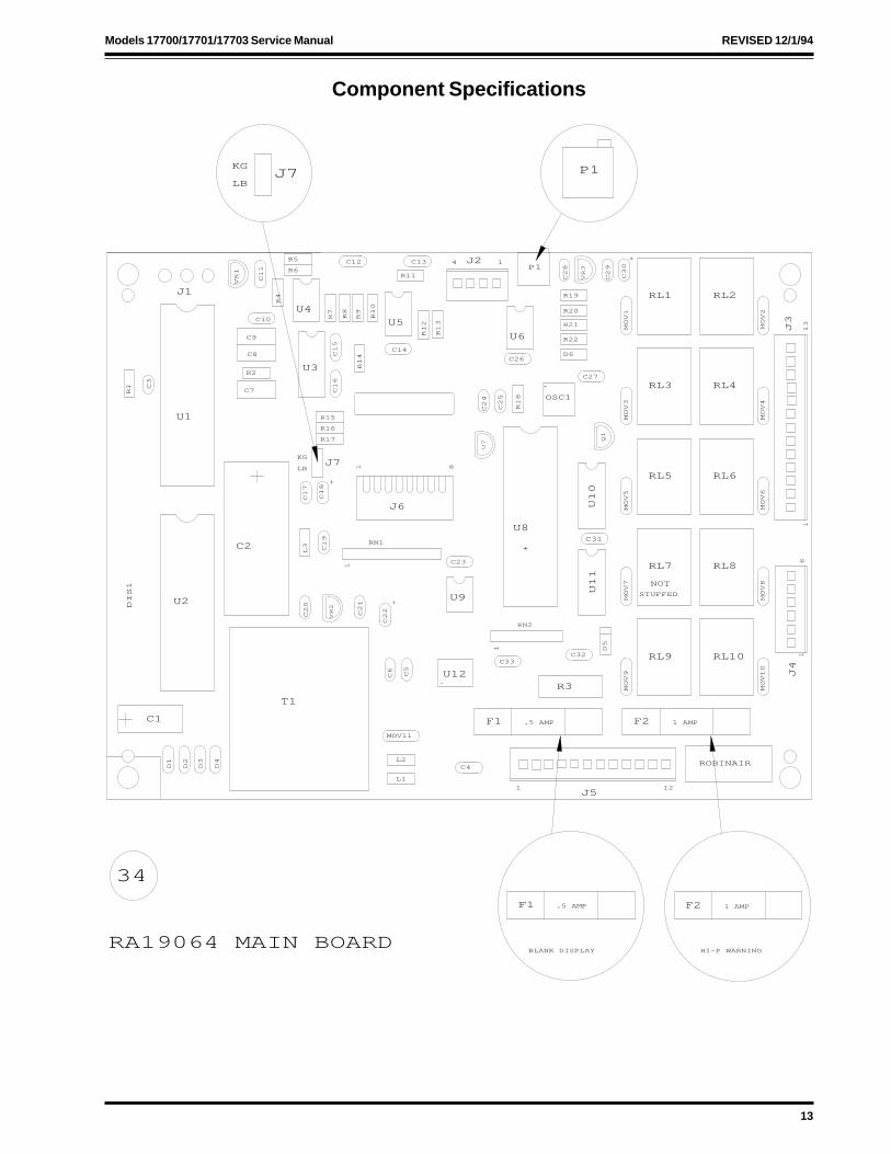
34
RA19064 MAIN BOARD
P1KG
LBJ7
1 AMP.5 AMPF1 F2
BLANK DISPLAY HI-P WARNING

14
ORIGINAL Models 17700/17701/17703 Service Manual
Component Specifications
REVISED 12/1/94
RA19064 REPLACEMENT MAIN BOARD
This board uses the previous basic functions withauto calibration, low side clearing, timed oilreturn and a 10-hour oil time change. The boardcan be programmed for a minimum vacuum time,oil change time and filter change time.
The board automatically defaults to a 15-minutevacuum time, 10-hour oil change and 300-poundfilter change. The board also has the CH-P warn-ing, which is initiated when recovery is engaged.If there is less than five (5) psi at the inlet of theunit, this prompt will appear.
The board can read the amount of refrigerantrecovered over a period of time (week or month,depending upon how often you want to check it).To access that function, you must enter manualdiagnostics and press the “3” key. The amountrecovered will be displayed. To “zero out” thedisplay, press the Shift/Reset and Enter keys.
You can also read the amount of refrigerant in thetank by accessing diagnostics and pressing the “7”key.
The following table gives the main board’s defaultcodes. Follow these steps to change the defaultcode.
1. Turn on the unit and press the Shift/Reset andEnter keys at the same time.
2. Press “9-4-9-4.” The message CAL2 shoulddisplay.
3. Press Enter and the current default code willdisplay.
4. Enter the new three-digit default code andpress Enter to store the code in the unit’smemory.
Default Code Table
CodeNumber 1 2 3 4 5 6
Vacuum Time(minutes) 0 10 15 20 25 30
Filter changeAmount (lbs.) 150 200 250 300 350 400
Pump OilTimer (hours) 5 10 15 20 25 30
RA19008 SCALE ASSEMBLY
36
15
Models 17700/17701/17703 Service Manual ORIGINAL
Component Specifications
CLOSED
RECOVER
RECYCLE
7
4
1
35
32
MAIN
POWER
ON
OFF
RESET
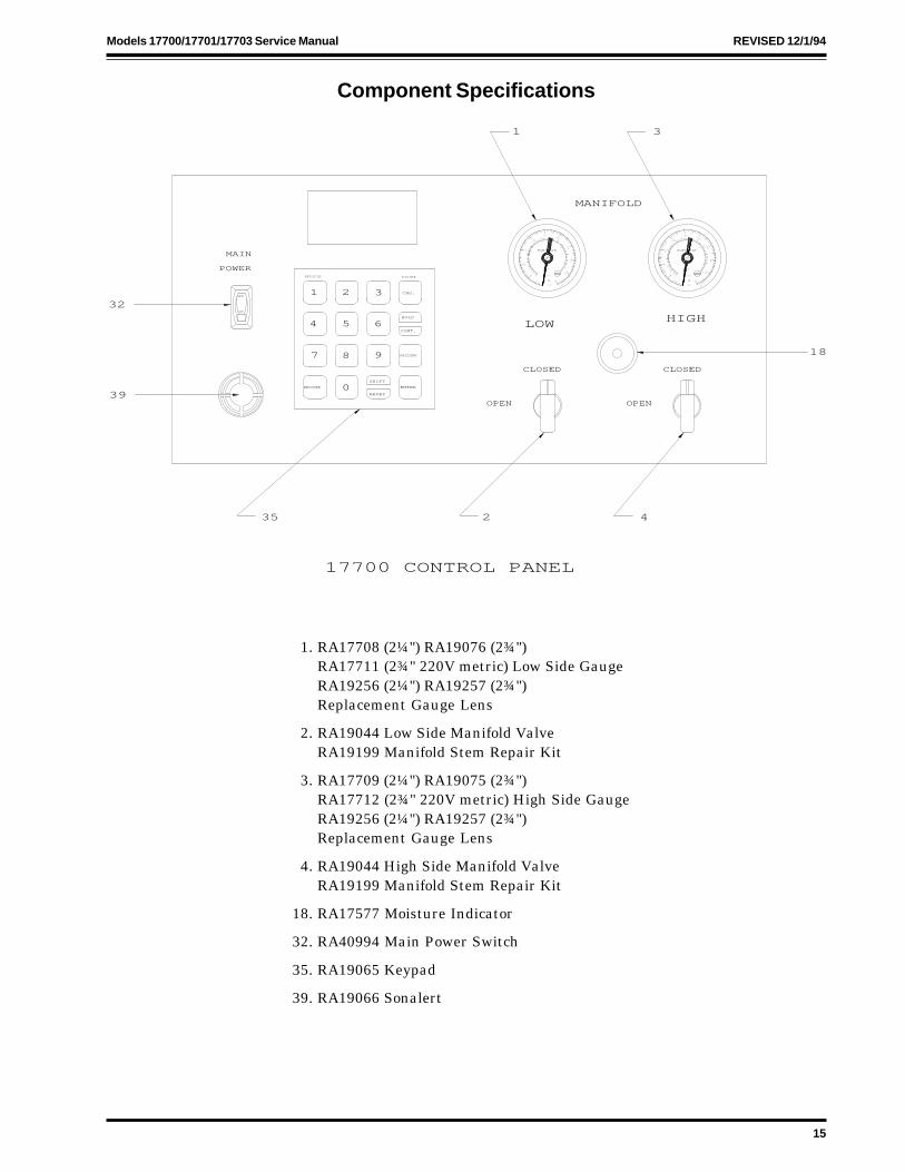
17700 CONTROL PANEL
OPEN
2 4
OPEN
VACUUM
ENTER
CONT.
HOLD
FILTER
65
8
0
9
SHIFT
2 3 CHG.
LOW
CLOSED
MANIFOLD
1 3
HIGH
18
psi
210
200
190
180
170150
140
120
100
80
60
40
500
450
400
350
300
250
200
150
100
50
0
F
ROBINAIR
MADE IN U.S.A.
R-12
psi
210
200
190
180
170150
140
120
100
80
60
40
500
450
400
350
300
250
200
150
100
50
0
F
ROBINAIR
MADE IN U.S.A.
R-12
39
1. RA17708 (2¼") RA19076 (2¾")RA17711 (2¾" 220V metric) Low Side GaugeRA19256 (2¼") RA19257 (2¾")Replacement Gauge Lens
2. RA19044 Low Side Manifold ValveRA19199 Manifold Stem Repair Kit
3. RA17709 (2¼") RA19075 (2¾")RA17712 (2¾" 220V metric) High Side GaugeRA19256 (2¼") RA19257 (2¾")Replacement Gauge Lens
4. RA19044 High Side Manifold ValveRA19199 Manifold Stem Repair Kit
18. RA17577 Moisture Indicator
32. RA40994 Main Power Switch
35. RA19065 Keypad
39. RA19066 Sonalert
REVISED 12/1/94

16
ORIGINAL Models 17700/17701/17703 Service Manual
Component Specifications
1 2 3
4 5 6
7 8 9
0
RECYCLE FILTER
CHG.
HOLD
CONT.
SHIFT
RESETENTERRECOVER
VACUUM
35
ADDThe recovery tank has less than 8 lbs. of refrig-erant left or is beginning the addprocess.
CALCalibrate the scale.
CH-FChange the filter-drier.
CH-PLess than 25 psi at inlet of machine.
CL-LLow side clearing routine is in progress.
CONContinuous; the vacuum pump will run continu-ously.
CPLComplete; cycle process is finished.
FILFilter-drier change-out is in process.
FULLRefrigerant tank is full.
HI-PHigh pressure; internal unit pressureis above 350 psi.
OILChange the vacuum pump oil. To reset, pressShift/Reset and Enter at the same time whilethe OIL message is displayed.
U-HIHigh pressure to vacuum pump.
SCALScale problem; scale may be broken or discon-nected, or tank weight has exceeded 80 pounds(36 kilograms).
99LBThe maximum amount displayed during recov-ery is 99 pounds (or 99 kilograms);reset the unit.
REVISED 12/1/94

17
Models 17700/17701/17703 Service Manual ORIGINAL
Component Specifications
27
TOP VIEW
6
FRONT VIEW
IN
RECOVER
INRECHARGE
IN
RECYCLING
31
24
8
7
23
6. RA17112 Inlet Check Valve
7. RA19006 Recovery SolenoidRA19258 Solenoid Rebuild Kit
8. RA17328 Vacuum Sensor
23. RA17424 Automatic Expansion Valve
24. RA19006 Recycling SolenoidRA19258 Solenoid Rebuild Kit
27. RA17329 Vacuum Pump Protection Switch
31. RA19006 Charging SolenoidRA19258 Solenoid Rebuild Kit
REVISED 12/1/94
18
ORIGINAL Models 17700/17701/17703 Service Manual
Component Specifications
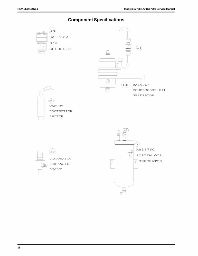
RA17522
N/O
SOLENOID
14
16
SEPERATOR
COMPRESSOR OIL
RA1906713
SEPERATOR
SYSTEM OIL
9
RA18760
EXPANSION
VALVE
AUTOMATIC
23
VACUUM
PROTECTION
SWITCH
27
REVISED 12/1/94

19
Models 17700/17701/17703 Service Manual ORIGINAL
Component Specifications
6 & 8 EACH RELAY
* NO CONNECTION TERMINALS
SHORT BLACK JUMPER
LONG BLACK JUMPER (W/FLAG)
2 4 6 8
2 4 6 8
"VACUUM PUMP RELAY"
"COMPRESSOR RELAY"
BLACK
*
0 1
PURPLE
BLACK
*
0 1
*
*
YELLOW RA17459 System RelayThe system relay energizes the compressor andallows the sensors to shut the unit off. The relayhas two sets of contacts which close when the coilis energized.
Contacts 0 & 1 are the coil contacts. When ener-gized, they should have 110 volts across theterminals. While voltage is applied, the coil formsa magnetic field pulling the 2 and 4 and the 6 and8 contacts together.
The 2 and 4 and the 6 and 8 contacts have powersupplied to one terminal of the pair. When the coilis energized, it closes the contacts and suppliespower to the mating contact.
TROUBLESHOOTING
Manual override ear not pulled in.
1. Check for proper voltage to the 0 and 1 con-tacts. If there is proper voltage, replace therelay. If there is not proper voltage, replacethe main board.
Manual override ear pulled in.
1. Check for proper voltage from the powersupply contact to the ground. If there is notproper voltage, check the voltage supplysource.
2. Check for proper voltage from the matingsupply contact to the ground. If there is notproper voltage, replace the relay.
Note: Use of an improper extension cord size candamage contact points.
REVISED 12/1/94

20
ORIGINAL Models 17700/17701/17703 Service Manual
Component Specifications
ORANGE
VACUUM
WIRES
SENSOR
8
RA17328 Vacuum SensorThe vacuum sensor is a normally closed sensor.If a 17" (± 2") vacuum is reached at the intake, theswitch opens and breaks the coil contacts, shut-ting off the unit.
The contacts are closed when anything above 17"is present in the lower cavity. When 17" isachieved in the lower cavity, the spring contacthas room to force away from the mating contact.
TROUBLESHOOTING
With pressure in the accumulator (open the oildrain valve to ensure pressure is present), theswitch should have continuity. If it does not,replace the switch.
If the unit is shutting off before reaching a 17"vacuum, inspect the inlet for obstructions beforereplacing the switch.
HIGH PRESSURE
CUT OUT
15
17072 High Pressure Cut OutThe high pressure cut out is a normally closedsensor designed to shut the unit off if the dischargepressure reaches 350 psi.
The pressure is detected through the orifice in thebase of the sensor. In the normal setting (less than350 psi on orifice) the 1 and 3 contacts are closed.When 350 psi is introduced to the orifice, the pres-sure forces up on the drive pin which forces thecenter contact to disengage the 1 and 3 contacts andengage the 1 and 2 contacts. When this takes place,the unit shuts off and turns on the high pressurelight.
REVISED 12/1/94

21
Models 17700/17701/17703 Service Manual ORIGINAL
Tubing Schematic
REVISED 12/1/94
(REF.)
FILTER
VACUUM PUMP(REF.)
111522
111863
SERVICE PORT
111801
OIL
HEAT EXCHANGER
110285
(REF.)
OIL DRAIN VALVE
113810 111796
110323
111864
111877 110334
COMPRESSOR
OIL DRAIN
111816
110319
110324
(REF.)
110291
111823
111803
110322114094
111421
768336
111812111807
111794
LOW SIDEHI
GH SIDE
LEGEND
CHECKVALVE
TEE
109855
111817
IN
(REF.)
SEPARATOR
RETURN OIL
111353
TUBE P/N
UNION
111795
111815
(REF.)
110311
105938
AIR PURGE INDICATOR
AIR PURGE VALVE
111247
HIGH SIDE
LOW SIDE

22
ORIGINAL Models 17700/17701/17703 Service Manual
Component Specifications and Service
4''. 30
UPRIGHT POSITIONDISCHARGE
WHITE
111041 MOUNT IN
111042
GRN
INTAKE
SUCTION
BLACK BOX
ELECT.
5 53 3
122 1
TOP
COMP.
10973812
COMPRESSOR SPECIFICATIONS
Type: 1/3 hp hermetic (piston type) com-pressor
Oil Capacity: 11 oz. of 150 viscosity refrigerationoil (ester refrigeration oil)
Amperage: 4-6/3-5 running amperage20-25/16-19 locked rotor amperage
Voltage: 110V/220V
PROCEDURE FOR CHECKING OIL LEVEL
1. Depressurize the unit following the instructionson page 2.
2. Remove the compressor from the unit.
3. Place the compressor on flat surface.
4. Tip the compressor 30 degrees (see figure above).At this angle, there should be oil inthe suction fitting.
PROCEDURE FOR ADDING OIL
1. Install a hose on the suction fitting and place theloose end of the hose into a bottle containing two(2) ounces of oil.
2. Start the compressor. Plug the intake fittingwith a cap, but leave the discharge open. Thecompressor will pull the oil from the bottle intoitself.
3. Recheck the oil level. If it is still low, keepadding two (2) ounces at a time until a properlevel is achieved. Be sure to check the oil levelbetween each addition.
TROUBLESHOOTING
Compressor won’t run.1. Check for proper voltage to compressor (110V/
220V). If there is no voltage, inspect the powersource for defects.
2. Jumper thermal overload. If the compressorruns, take an amp draw of the compressor. If itis okay, replace the thermal overload. If it isdrawing locked rotor amperage, replace thecompressor. If there is no amp draw, inspect thestart components and replace if necessary.
Compressor runs, no suction.1. Cap the intake fitting.
2. Install a low side gauge on the suction fitting.
3. Be sure nothing is connected to the discharge.
4. Start the compressor and monitor the suctionreadings (it should pull a 25" vacuum).
5. If the compressor has weak suction, check theoil level and add oil if necessary.
6. If the oil level is okay or oil was added with noimprovement, replace the compressor.
Compressor runs, no discharge.1. Check the oil level and add oil if necessary.
2. Install a high pressure gauge on the dischargeport.
3. Check the intake and suction fittings for ob-structions.
4. Start the compressor. Pressure should build to350 psi in about four (4) minutes. If pressuredoesn’t rise or reach at least 350 psi, replace thecompressor.
REVISED 12/1/94

23
Models 17700/17701/17703 Service Manual ORIGINAL
Troubleshooting
UNIT WILL NOT COME OUT OF CL-LCOMPRESSOR RUNSUNIT WILL NOT RECOVER
1. If the unit is being run through an extensioncord, eliminate it’s use.
2. Disconnect the high and low side hoses from thevehicle with the gauge valves open. If thepressure on the gauges drops while the displaysays CL-L, the recovery solenoid needs rebuilt orcleaned.
3. Check the oil drain valve. Verify that it is closedand not bleeding through.
4. Install the low side hose on the service port withthe low side valve closed. Look at the pressurereading. If the pressure is below 20", test thevacuum sensor for continuity. If the gauge haspositive pressure, go to Step 5. If the vacuumsensor has continuity, replace it.If it doesn’t have continuity, check the vacuumsensor wires for continuity. If the wires havecontinuity, replace the main board.
5. Close the liquid tank valve. If the pressurestarts dropping on the gauge and starts arecovery sequence, clean and rebuild the recy-cling solenoid.
6. Inspect the filter for flow obstructions and leaksaround the gasket area. Note that the fittings onquick disconnects should only be hand tight.Replace the gaskets if needed. When installinggaskets, be sure to lubricate them with vacuumgrease or refrigerant oil if needed.
7. Verify that the equalization solenoid is receiving110 volts from the main board. If it is not, checkthe solenoid’s power supply wires for continuity.If they have continuity, replace the main board.
8. If the equalization solenoid is receiving power,check the equalization solenoid for bleed throughto the suction side of the compressor. Replace thesolenoid if it is bleeding through while receivingpower. Go to Step 9 if the solenoid is functioningproperly.
9. Check the compressor discharge and suctionpressure (see page 22). Replace the compressoras necessary.
REVISED 12/1/94

24
ORIGINAL Models 17700/17701/17703 Service Manual
Troubleshooting
UNIT WILL NOT COME OUT OF CL-LCOMPRESSOR IS OFFUNIT WILL NOT RECOVER
1. If unit is being run through an extension cord,eliminate it’s use.
2. Remove the shroud and look for loose wires.
3. Check for 110 volts to the coil of the compressorrelay (energized). If there is no voltage, checkthe wires from the main board to the compressorrelay for continuity. If they have continuity,replace the main board.
4. If the compressor relay is energized (receiving110 volts to the coil), check for voltage from #4contact to ground with a volt meter. Thereshould be 110 volts. If there is no voltage,replace the compressor relay.
5. Check for voltage to the compressor. If thereis no voltage, inspect the wires between thecompressor and the compressor relay for conti-nuity. Repair or replace as necessary.
6. If voltage is present at the compressor, jumperthe thermal overload. If the compressor runs,check the compressor amp draw. If it is drawinghigher than 6 amps or not running, replace thecompressor. If the compressor is cool anddrawing low amperage, replace the thermaloverload.
1. Verify that both tank valves are open.
2. Check the tank pressure. It should not exceed300 psi. If it is high, bleed the pressure down to200 psi using the air purge.
3. Check the red vapor tank hose for properinstallation. Be sure there is no obstruction atthe tank fitting.
4. Check the 1-amp fuse on the back of the mainboard for continuity and replace if necessary. Ifthe replacement fuse blows again, inspect thecompressor relay for shorted contacts andreplace as necessary.
5. Inspect the wires between the high pressure cutout and the main board for continuity. Repair orreplace as necessary.
6. Inspect the recovery check valve for obstructionsand replace or repair as necessary. If the checkvalve is okay, go to Step 7.
7. Replace the high pressure cut out and retest theunit.
UNIT WILL NOT COMPLETE RECOVERYDISPLAY READS HI-P
REVISED 12/1/94

25
Models 17700/17701/17703 Service Manual ORIGINAL
Troubleshooting
1. Check the tank weight. If the tank is full,replace the tank.
2. Recalibrate the scale if necessary. See the scalecalibration instructions on page 34.
3. Adjustment of the P-1 pot (located on the mainboard; see page 13 for location) may be neces-sary. Note that not all main boards have a P-1pot; it depends on the production date of themain board.
1. Check the scale calibration and recalibrate ifnecessary. See the scale calibration instructionson page 34.
2. Check the scale’s cable to be sure it is connectedto the main board. If the main board has morethan one scale connection, verify that theinternal/external jumper is in the proper loca-tion.
3. Replace the scale if previous attempts havefailed.
1. Verify that there is positive pressure on theunit’s manifold gauges. If there is no positivepressure, connect to a vapor supply source andattempt recovery again.
2. Look for loose or broken wires in the unit.
3. Connect a pressure gauge to the service port andcheck for positive pressure. If pressure ispresent, go to Step 4. If there is no positivepressure, verify that the inlet check valve isoperating properly. Also verify that the recoverysolenoid is opening and allowing flow. Repair orreplace as necessary.
4. Check the vacuum sensor for continuity. Replaceif there is no continuity.
1. If there is less than 5 psi at the inlet, attemptrecovering from a positive pressure source.
2. Verify that the wires that control the vacuumpump protection switch have continuity.
3. If there is more than 5 psi at the inlet, replacethe vacuum pump protection switch.
4. If the sensor is operating properly, press Con-tinue to override.
DISPLAY READS FULL
DISPLAY READS SCALE
DISPLAY READS CPL
DISPLAY READS CH-P
REVISED 12/1/94

26
ORIGINAL Models 17700/17701/17703 Service Manual
Troubleshooting
1. The filter change time has elapsed. To reset thetimer, press Shift/Reset and Enter at the sametime while CH-F is on the display. Note that onthe newer style main boards the filter change-out routine must be performed to reset thetimer.
2. If the CH-F warning doesn’t disappear afterattempting to reset the timer, replace the mainboard.
1. If the display does not respond to keypadcommands, verify that the keypad isplugged in.
2. If the keypad is plugged in but still not respond-ing, replace the keypad.
3. If the keypad is functional, a tone will be heardwhen a key is pressed.
4. Replace the main board if commands are notbeing accepted.
1. Verify that the manifold gauge valves are open.
2. Verify that the high and low side hoses are tightat all fittings.
3. Verify that the vacuum hose is snug at bothends and not obstructed. Inspect hose gaskets forleaks.
4. Verify that the IsoValve (if so equipped) is in theOpen position.
5. Check for suction at the intake of the vacuumpump. If there is no suction, replace the vacuumpump.
6. Remove the unit’s shroud and look for loosewires to the vacuum solenoids.
7. Check for 110 volts to the vacuum solenoids. Ifvoltage is present, rebuild the solenoids orinspect for debris.
8. If there is no voltage to the vacuum solenoids,inspect the wires between the vacuum relay forcontinuity. If they are okay, replace the mainboard.
DISPLAY READS CH-F
DISPLAY READS “0.00 VACUUM PROGRAMMINUTES
REVISED 12/1/94
UNIT WILL NOT EVACUATEPUMP RUNS

27
Models 17700/17701/17703 Service Manual ORIGINAL
Troubleshooting
1. Check for pressure at the vacuum pump protec-tion switch (recover before evacuating).
2. Unplug the switch. If U-HI goes out, check forpressure at the sensor.
3. If there is no pressure at the sensor, replace thesensor.
4. If U-HI remains on the display, replace the mainboard.
1. Verify that the vacuum pump is plugged in.
2. If the vacuum pump is equipped with anOn/Off switch, verify that it is turned on.
3. Check the voltage at the vacuum pump recep-tacle.
4. If there is proper voltage, check that the vacuumpump is not overfilled with oil. If itis, drain the oil from the vacuum pump. Startand refill the vacuum pump properly. If it is notoverfilled, replace the vacuum pump.
5. If there is not proper voltage, remove the coverand look for loose wires.
6. Check for voltage to the coil of the vacuum pumprelay, If there is no voltage, inspect the wiresbetween the vacuum pump relay and the mainboard for continuity. If the wires are okay,replace the main board.
7. If voltage is present at the vacuum pumprelay coil, replace the relay.
8. Check for voltage from #4 to ground. If there isno voltage, replace the relay.
UNIT WILL NOT EVACUATEPUMP IS OFFU-HI ON DISPLAY
TIMER COUNTING DOWN
REVISED 12/1/94
28
ORIGINAL Models 17700/17701/17703 Service Manual
Troubleshooting
1. Check that all recovery tank hoses are installedproperly.
2. Verify that the recovery tank valves are com-pletely open.
3. Check that there is a minimum of 10 lbs. ofrefrigerant in the recovery tank.
4. Install the low side of a manifold gauge set to theservice port.
5. If positive pressure is present at the service port,remove the unit’s cover and look for loose wiresto the vacuum sensor. If there are no loosewires, check for continuity on the vacuumsensor. If there is no continuity, replace thevacuum sensor.
6. Inspect the orange wires between the mainboard and the vacuum sensor for continuity.If the wires and the vacuum sensor have conti-nuity, jumper the orange wires together.
7. Start recycling if the service port is being pulledinto a vacuum. Look for loose wires to therecycling solenoid and verify that 110 volts isbeing sent to the recycling solenoid. If there is novoltage, inspect the controlling wires for continu-ity. Replace the main board if the wires havecontinuity.
8. If the recycling solenoid is receiving 110 volts,inspect the liquid line strainer bulb (some unitshave the strainer installed behind the hosegasket in the liquid hose) for obstructions.Replace or clean as necessary.
9. If the strainer is not plugged, attemptrecalibrating the expansion valve. If you areunable to recalibrate the expansion valve,rebuild the recycling solenoid and replace theexpansion valve.
10. If all previous attempts have failed, replace themain board.
UNIT WILL NOT RECYCLERECYCLE PROMPT IS OFFCOMPRESSOR IS OFF, NO FLOW
REVISED 12/1/94
29
Models 17700/17701/17703 Service Manual ORIGINAL
Troubleshooting
UNIT WILL NOT RECYCLEPROMPT IS ON, NO FLOW
1. Check that all recovery tank hoses areinstalled properly.
2. Verify that the recovery tank valves are com-pletely open.
3. Check that there is a minimum of 10 lbs. ofrefrigerant in the recovery tank.
4. Check the oil drain valve for leaks (the valveshould be closed).
5. Inspect the liquid line strainer for debris. Cleanor replace as necessary.
6. Install the low side of a manifold gauge set to theservice port.
7. Verify that the expansion valve calibration is at35 psi. Always check the expansion valvepressure while recycling for ten minutes with atleast 10 lbs. of refrigerant in the tank.
8. Inspect the filter for flow obstructions. Ensurethat the gaskets are not crushed but sealing(replacement gasket #40084).
9. Check the equalization solenoid for internalbleed through and replace if necessary.
10. If the compressor is not running, verify that 110volts is being supplied to the compressor. If it isnot receiving 110 volts, check the wiring forcontinuity and the system relay for properoperation.
11. If the compressor is receiving 110 volts but notrunning, inspect the compressor start compo-nents and check the amp draw (see page 22).Replace the compressor as necessary.
12. If the compressor is running, check the compres-sor suction and discharge pressures as well asthe oil level. Add oil if needed. If the oil level isadequate but there is no suction or dischargepressure, replace the compressor.
REVISED 12/1/94

30
ORIGINAL Models 17700/17701/17703 Service Manual
Troubleshooting
UNIT WILL NOT RECYCLEPROMPT IS ON, WITH FLOW
1. Verify that the recovery tank valves are com-pletely open.
2. Check that there is a minimum of 10 lbs. ofrefrigerant in the recovery tank.
3. Replace the filter and recycle for a minimum of1½ hours.
4. Replace the moisture indicator if it is notturning green.
1. Verify that the liquid tank valve is open.
2. Verify that the manifold gauge valves arecompletely open and unobstructed.
3. Inspect the liquid hose for proper installation onthe tank and look for crushed hose gaskets.
4. Verify that the liquid line screen is unob-structed. Replace or clean as necessary.
5. Verify that the main board has accepted thecharge program.
6. Remove the unit’s cover and look for loose wires.
7. If the main board does not accept the program,replace the main board. Ensure that the keypadis sending a program signal before replacing it.If the keypad is sending a signal, an audible tonewill be heard when the keys are pressed.
8. Check the voltage at the charging solenoid. Ifthere is no voltage, inspect the wires for continu-ity. If the wires are okay, replace the mainboard. If 110 volts is going to the solenoid,rebuild or replace the solenoid.
UNIT WILL NOT CHARGENO PRESSURE ON GAUGES
REVISED 12/1/94

31
Models 17700/17701/17703 Service Manual ORIGINAL
Troubleshooting
1. Verify that the Quick Seal hose ends are en-gaged as well as the Schrader cores on thesystem. Adapters on the high and low side hosesmust be used to guarantee proper access to thesystem.
2. Verify that a minimum of 10 lbs. of refrigerantis in the recovery tank.
3. Check that the scale is able to move freely andthat the tank strap does not hinder tank move-ment.
4. Verify that charging is being attempted throughboth the high and low side hoses.
5. Check for proper voltage to the charging solenoidand see if the voltage is being erratically droppedto the charging solenoid.If the voltage is fine, go to Step 6. If the voltageis not fine, replace the main board.
6. Close the high side valve. Start the vehicle andpull the remaining charge in on the low side ofthe system. When the remaining charge hasbeen pulled from the tank, the charging solenoidwill close preventing a possible overcharge.
UNIT WILL NOT CHARGEPRESSURE ON GAUGES
REVISED 12/1/94

32
ORIGINAL Models 17700/17701/17703 Service Manual
RA19064 Replacement Main Board
The main board is used in the 17700 Series R-12or the 34700 Series R-134A units. The boards havehad several revisions since their first introductionin May of 1991. These boards can easily be identi-fied by the six-digit part number stenciled inwhite lettering on the back side of the main board.
FIRST GENERATION BOARD (#111367)
This board performed several basic functions:
• Recovery automatic shut down.• Display should read amount recovered.• Programmable vacuum time.• Programmable charge amount.• Manual diagnostics:
#1 starts vacuum pump#2 engages add sequence#5 turns on the entire display#6 displays scale readings
SECOND GENERATION BOARD (#111961)
This board performed the same basic functions,but added these features:
• Auto scale calibration• Vacuum pump oil change timer
The new auto calibration feature allows the userto easily and accurately calibrate the scale (seeauto scale calibration instructions on page 34).The ten-hour timer on the oil change procedurefor the vacuum pump was also added.
THIRD GENERATION BOARD (#113139)
This board performed all the basic functions, includ-ing auto calibration and the vacuum pump oil timer,and also added these new functions:
• Low side clearing• Timed oil return to the compressor
The low side clearing feature allows the user toreceive a more accurate reading of the amount ofrefrigerant recovered. To do this, the board does notapply power to the recovery solenoid when therecovery key is pressed. Instead, the solenoidremains closed until the inlet tubing is in a 17"vacuum. When a vacuum is reached, the vacuumsensor opens, the main board detects that and therecovery solenoid opens. After the recovery solenoidopens, the vacuum sensor closes and the scale showsthe amount of refrigerant being recovered. Beforethe recovery solenoid opens, the screen will displayCL-L. This board also has timed oil return every ten(10) minutes that lasts for three (3) seconds,whereas the older boards only allowed oil to returnwhen the compressor shut off.
REVISED 12/1/94

33
Models 17700/17701/17703 Service Manual ORIGINAL
RA19064 Replacement Main Board
FOURTH GENERATION BOARD
These boards were designed for specialty units.These boards all have the same basic functions,along with low side clearing and auto calibrationcapabilities, with specific programs for each unit:
113285 (17534 GM)
• CH-P message alerts the user that there isless than 5 psi at the inlet
• 15-minute minimum vacuum time
113429 (34700 OTC)
• 20-minute minimum vacuum time• 15-hour vacuum oil timer
112343 (17534, NI, NIA, INF)
• 20-minute minimum vacuum time• No refrigerant counter• No filter change warning
113286 (17534 BMW, BMWA)
• 30-minute minimum vacuum time
FIFTH GENERATION BOARD
This board will be the replacement for all previousboards. It uses all the previous basic functionswith auto calibration, low side clearing, timed oilreturn and 10-hour oil time change:
• Programmable settings for oil changes, filterchange time
• Running refrigerant counter• Diagnostics 7 counter for refrigerant weight
This board can be programmed for a minimumvacuum time, oil change time and filter changetime. The board automatically defaults to a 15-minute vacuum time, 10-hour oil change and 300-lb. filter change. This board also has the CH-Pwarning initiated when recovery is engaged if lessthan 5 psi is at the inlet. It can read the amount ofrefrigerant recovered over a period of time (week,month) depending upon how often the user wantsto check it. To access that function, the user mustenter manual diagnostics and press the 3 key. Theamount recovered is displayed and can be “zeroedout” by pressing the Shift/Reset and Enter keys atthe same time. The user can also read the amountof refrigerant in the tank by accessing diagnosticsand pressing the 7 key.
SIXTH GENERATION BOARD (#114240)
This board is identical to the fifth generationboard except for the addition of one feature:
• Add refrigerant when less than 6 lbs. ofrefrigerant is in the tank and a charge isrequested
When the unit is in the program charge mode andan amount is requested that will drop the recoverytank’s capacity below 6 pounds, an ADD messageappears on the display. This notifies the user thatthere is insufficient refrigerant in the tank toproperly charge the system.
SEVENTH GENERATION BOARD (#115309)
This board had no feature changes, but the overalllayout of components changed.
REVISED 12/1/94

34
ORIGINAL Models 17700/17701/17703 Service Manual
RA19008 Replacement Scale
There were two types of scales used on the 17700series units. Both scales can handle a 50-lb. tankand have the same overfill protection shut off of 73lbs. Where the two scales differ is in the method ofcalibration. The first type of scale is calibrated withthe use of trim pots mounted on the scale board. Thesecond type scale has no scale board and is cali-brated through programming of the main board. Thetwo scales also have different design harness connec-tions at the main board. The two types of scales havebeen manufactured by different vendors and theiridentification can be determined using the ScaleSpecification chart on page 35.
CHECKING THE SCALE ACCURACY
The method of checking the scales accuracy is thesame for both types of scales.
1. Turn on the Main Power switch and press theShift/Reset key until the program prompt ishighlighted on the screen.
Note: If the unit is just being turned on, the screenwill default to a program mode. When the screenhas the program prompt highlighted, press theShift/Reset and Enter keys at the same time. Thescreen will be blank when the manual diagnosticmode has been entered properly.
2. Press the 6 key to turn the scale into a directreading weight scale. The scale should read ± 0to 2 pounds with nothing on it (other than theempty platform). The scale will need recalibratedif the reading is out of tolerance.
Note: If the scale does not react to testing, verifythat the scale is plugged into the main board.
RECALIBRATING AN OLD-STYLE SCALE
1. Unplug the unit from the power source.
2. Remove the scale platform.
3. Remove the scale box cover and the four (4) scalemounting nuts.
4. Lift the scale assembly out of the box and turn itto rest on the scale box with the adjusting potsfacing out. Replace the platform on the scaleassembly.
CAUTION
Do not remove the scale board from the mountingplate to attempt calibration or the board could beshorted and possibly damaged.
5. Plug the unit into the power source and turn onthe Main Power switch.
6. Press Shift/Reset and Enter on the keypad at thesame time. Press the 6 key and the scale weightwill appear.
7. With only the scale platform on the scale, adjustthe high gain pot until the display reads 0.00.
8. Place a known weight of 20 lbs. on the scale.The display should read 20 lbs. If it does not,place an additional 20 lb. weight on the scale.The display should read 40.00 lbs. plus or minusthree percent. If it does not, adjust the high gainpot to read 40.00 lbs.
9. Remove the second 20 lb. weight. The displayshould read 20.00 lbs. plus or minus threepercent. If it does not, adjust the low gain pot toread 20.00 lbs.
Note: Adjustments between 20 and 40 lbs. may needto be repeated to ensure proper calibration.
10. Remove all weight from the platform. Thedisplay should read 0.00 lbs., plus or minus onelb. Place a 20 lb. weight on the platform. Thescale should read between 19.40 and 20.60 lbs.
Note: If the scale won’t calibrate, replace the scale.When calibration is complete, reassemble the scalebox.
REVISED 12/1/94

35
Models 17700/17701/17703 Service Manual ORIGINAL
RECALIBRATING A NEW-STYLE SCALE
1. Remove all weight from scale platform.
2. Turn on the Main Power switch.
3. Press the Shift/Reset and Enter keys at thesame time.
4. Press 8-7-8-7 on the keypad; the display willshow A-1.
Note: If you press any other key before the 8-7-8-7sequence, you will not be able to enter the auto-matic calibration routine.
5. Press the 0 key and then press Enter on thekeypad. The display shows 0.00 and thenchanges to the message A-2.
6. Place a known weight (between 10 and 80 lbs.)in the center of the platform. Enter that weighton the display using the keypad, then pressEnter. The display returns to the vacuum mode.
7. Check the scale accuracy by pressing Shift/Resetand Enter at the same time. When the diagnos-tics mode is entered (the display will be blank)press #6. The display will show the amount ofweight on the scale platform.
Note: If the scale won’t calibrate, replace the scale.
SETTING THE P-1 POT
1. Press Shift/Reset and Enter at the same time.When the diagnostics mode is entered (thedisplay will be blank), press the 6 key. Thedisplay will show the amount of weight on thescale platform.
2. Add weight to the scale platform until HOLDappears on the display. Then turn the P-1 potclockwise to increase the amount you can put onthe scale before the HOLD indicator appears.Turning the P-1 pot counterclockwise decreasesthe amount of weight allowed on the scale beforeHOLD appears.
3. Set the P-1 pot so that HOLD appears with 73pounds on the scale. Lift the weight on the scaleand HOLD will disappear.
RA19008 SCALE SPECIFICATIONS
Old-style scales were used on units untilMarch of 1992.
Manufacturer: RobinairApplication: 17700 style unitsCapacity: 50-lb. tanksControl: Circuit board on scaleCable: Gray in colorConnector: 5 pinsDimensions: 6¾"W, 6"LMaximum Capacity: 81.74 lbs.
New-style scales were used on units afterMarch of 1992.
Manufacturer: RobinairApplication: 17700 style unitsCapacity: 50-lb. tanksControl: Main PC boardCable: Gray in colorConnector: 4 pinsDimensions: 6¾"W, 6"LMaximum Capacity: 81.74 lbs.
Manufacturer: Tedea HuntleighDate first used: 7/29/93Application: 17700 style unitsCapacity: 50-lb. tanksControl: Main PC boardCable: Black in colorConnector: 4 pinsDimensions: 5¾"W, 7½"LMaximum Capacity: 81.74 lbs.
This scale could give floating scale readingsand should be replaced if giving questionableperformance:
Manufacturer: HITECApplication: 17700 style unitsCapacity: 50-lb. tanksControl: Main PC boardCable: Gray in colorConnector: 4 pinsDimensions: 5¾"W, 7½"LMaximum Capacity: 81.74 lbs.Date first used: 8/16/93
RA19008 Replacement Scale
REVISED 12/1/94

36
ORIGINAL Models 17700/17701/17703 Service Manual
Diagnostic Procedures
To enter the diagnostics program, press the Shift/Reset and Enter keys at the same time when thedisplay is blank. Then press these keys for thesefunctions:
Press “1” Vacuum pump runs continuously
Press “2” Add prompt displays, compressor starts
Press “3” Total amount of refrigerant recovered todate displays
Press “4” Not used
Press “5” All LCD information displays
Press “6” Total weight on scale displays
Press “7” Total weight on scale less 27 lbs. dis-plays
Press “8” Not used
Press “9” Not used
Press “0” Not used
Press Shift/reset and Enter, then press Shift/Resetand Filter at the same time to enter the nextdiagnostics level.
Press “1” Actuates the air purge solenoid, if soequipped
Press “2” Not in use
Press “3” Actuates the equalization solenoid
Press “4” Actuates the compressor
Press “5” Actuates the vacuum pump
Press “6” Actuates the recovery solenoid
Press “7” Actuates the recycling solenoid
Press “8” Actuates the charging solenoid
Press “9” Actuates the vacuum solenoid
REVISED 12/1/94

37
Models 17700/17701/17703 Service Manual ORIGINAL
Function Test Guide
RECOVERY TEST
1. Turn on the Main Power switch.
2. Connect the loose end of the low side hose tothe service port located between the filter andaccumulator.
3. Close the low side manifold valve.
4. Open the high side manifold valve.
5. Verify that all tank hoses are properlyattached to the recovery tank.
6. Completely open both tank valves.
7. Press the Recover key; the compressor shouldstart and the low side gauge should pull into a17" vacuum.
Note: If the unit has low side clearing, the low sidegauge will pull to a 17" vacuum and start therecovery process (recovery is engaged when thescale reading displays). The low side gauge shouldpull to a 17" vacuum again and the unit will shutoff.
8. When recovery is complete, the display showsa scale weight and then the message CPL.
9. The low side manifold gauge should buildpositive pressure and a pressure transfershould be heard. This is the result of theequalization solenoid opening and returningoil to the compressor. If no pressure riseoccurs, the equalization solenoid and itstubing should be checked for obstructions
10. Disconnect the low side hose from the serviceport, and open the low side manifold valve.
11. Press the Recover key; the unit should recoverto 17" of vacuum and shut off.
EVACUATION & RECYCLE TEST
The recovery tank must have at least 10 lbs. ofrefrigerant in it to perform this test.
1. Close the high side manifold valve.
2. Connect the loose end of the high side hose tothe service port.
3. Program a 20-minute vacuum into main boardand start an automatic vacuum process. Thevacuum pump should start.
4. Verify that the low side manifold valve is open.
5. The low side gauge should start registering avacuum.
6. Within 10 to 15 seconds of the vacuum pumpstarting, the RECYCLE prompt should appearon the display and a click will be heard (thecompressor is starting and the recyclingsolenoid is being energized).
7. After five (5) minutes the low side gaugeshould be in a 29" to 30" vacuum and the highside gauge should rise to around 30 to 40 psi(expansion valve pressure).
8. After 20 minutes of recycling the moistureindicator should turn mint green, signifyingthe refrigerant is dry.
9. When the unit shuts off automatically (com-pletes the vacuum process), disconnect thehigh side hose from the service port.
10. The low side manifold gauge valve should holda vacuum. If it does not, inspect Quick Sealhose ends for leaks.
11. Close the tank’s vapor valve.
12. Disconnect the vapor hose from the tank.
13. Using a separate manifold gauge set, verifythat the manifold gauge valves are closed.
14. Connect the tank’s vapor hose to the high sideof the separate manifold gauge set.
15. Connect a hose between the center port of thehand-held manifold gauge set to the tank’svapor fitting.
16. Open the tank’s vapor valve, but do not openthe hand-held high side manifold gauge valve.
17. Press Shift/Reset on the keypad.
18. Press Shift/Reset and the 1 key at the sametime. The unit will begin recycling and thehigh side manifold gauge will show increasingpressure.
19. The unit will shut off when the high sidemanifold gauge shows pressure of 350 psi (±20psi) and the display will read HI-P.
REVISED 12/1/94
38
ORIGINAL Models 17700/17701/17703 Service Manual
Function Test Guide20. The pressure on the high side gauge should
hold for at least three (3) minutes. If thepressure drops instantly or bleeds off steadily,the recovery check valve needs to be replaced.
21. After checking for pressure loss, slowly openthe high side manifold valve to equalize theunit and tank pressure. Once the pressure isequalized, close the vapor tank valve.
22. Close the high side manifold valve and discon-nect the hose between the tank’s vapor valveand the manifold gauge set at the tank end.
23. Disconnect the tank’s vapor hose from themanifold gauge set.
24. Reconnect the tank’s vapor hose to the tank’svapor valve.
25. Open both manifold gauge valves and pressthe Recover key.
30. Allow the unit to recover until it automaticallyshuts off.
CHARGING AND SCALE TEST
1. Turn on the Main Power switch.
2. Press Shift/Reset and Enter at the same time,then press the 6 key.
3. Check the scale accuracy and recalibrate ifnecessary (see page 34).
4. Connect the high and low side hoses to thevapor and liquid valves of a separate refillablecylinder.
5. Program a 2-lb. charge into the main board.
6. Start the automatic charging process. Thecharging process will stop when the pro-grammed amount of weight has been removedfrom the scale and the display will show themessage CPL.
7. Recover the refrigerant charged into the tank.
Note: To ensure a complete charge, recycle for atleast five (5) minutes before attempting to charge.
Labor RatesRobinair authorizes a 1¼ hour charge to trouble-shoot and complete a full function test on units thatare covered under factory warranty (including leaktesting). The authorized time for parts replacementis 15 minutes per part. Some items require anadditional amount of time to facilitate installation.These items and their times are listed below. Ifrepairs are estimated to exceed three (3) hours, priorauthorization from Robinair is required.
Part No. Component Total Time
RA17424 Expansion Valve 30 minutes
RA19006 Recycling Solenoid 45 minutes
RA19006 Recovery Solenoid 45 minutes
RA19064 Main Board 30 minutes
RA18760 System Oil Separator 30 minutes
The standard way of repairing a RA19006 solenoid isto use the RA19258 Solenoid Rebuild Kit. If asolenoid must be replaced it must be described indetail on the warranty to justify its replacement andreimbursement.
Robinair considers filters to be a consumable item;they are not covered under warranty. This includesparts and labor.
MISCELLANEOUS REPLACEMENT PARTS
Item Part No.Decals: Enviro-Charge 111786
Keystroke 111867Phone Sticker 109076
Handle Cap 108062Heyco Bushing 100385Shroud: Right 111355
Front 111357Left 111356
Tank Handles: Blue RA19206Red RA19207
Vacuum Pump Mounting Brackets:Front 111609Rear 111526
REVISED 12/1/94