modelling seashells shapes and pigmentation patterns...
TRANSCRIPT
Modelling Seashells Shapes and Pigmentation Patterns:Experiments with 3D Printing∗
Francesco De ComiteUniversity of Lille, Sciences and Technology,
AbstractThis paper describes the method I used to generate realistic 3D printed seashells, from the point of view of theirgeneral shape and of the patterns that decorate them. The method, and the associated program are general enough tocover a large range of existing seashell specimens. Examples are given. Comparisons with previous works are made,limits are highlighted, giving directions for future works.
Introduction
Apprentice painters used to learn their art by copying the masters again and again. Programmers like thechallenge of imitating existing things. Part of the challenge is to write short and simple programs, using asfew parameters as possible. Modelling seashells growth and patterns is a good example of such a challenge.
Interest in the shape of shells began with Moseley [6] in 1838, who pointed out the role of the loga-rithmic spiral in the shell coiling. These observations were validated experimentally by d’Arcy Thompson[8] at the beginning of the 20th century. First computer representations of seashell shapes were made byRaup in 1962 [7], in the form of cross-sections of shell. Raup developed also wire-frame representations. Amore detailed chronology of computer representations of seashells can be found in Fowler & al. [3]. Evenif some progress were made, until in the 90’s programmers were limited in the accuracy of their models bythe lack of computer memory. The description of accurate models requires millions of bytes of data, evenif you don’t take into account the information related to the pigmentation pattern. If we consider that thehistory of seashell shape simulation is closely connected to the development of the graphic capacities ofcomputers, the advent of 3D printers should have encouraged programmers to use this new tool, in order toproduce quite exact copies of existing shells. However, this does not seem to be the case. The only exampleI found at this time (April 2017) is David Bachman’s artwork Shell-f Like, presented at 2015 Bridges ArtExhibit. If I compare Bachman’s [1] work to my method, I can notice several differences: Bachman usedpost-processing to make his shell more realistic by modelling the aperture, and mapped the photograph of areal seashell pattern for colouring the model. In my method, I don’t use post-processing, and pigmentationpattern is computed, as explained in section Modelling Surface Patterns. Bachman also used a very use-ful professional program (Rhino/Grasshopper), but part of my challenge was to use only open-source tools(Blender). I used Rhino/Grasshopper only in the early stages of the project, in order to verify its feasibility.
The rest of the paper is organized as follows: The next section will describe the method used to generateshell shapes, and the following section will deal with pigmentation pattern generation. I will compare mywork to previous ones. I will show the points were I was able to go further, and also the limits I was not ableto go over. Pictures of successful 3D prints will demonstrate the validity of the method.
∗This work was supported by European funds through the program FEDER SCV-IrDIVE and by French National ResearchAgency (ANR-11-EQPX-0023).
Bridges 2017 Conference Proceedings
189
The External Surface
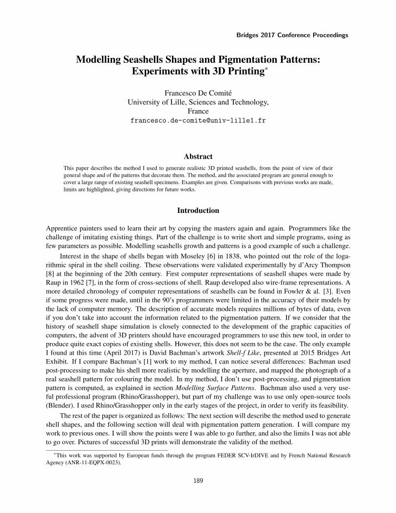
Every shell exterior surface can be seen as the envelope of a generating curve (the aperture) which centermoves along a helical spiral, while rotating around the vertical axis. More formally, let r be the distancefrom the center of the aperture to the vertical axis, z the height of the center, and θ the angle of rotation alongthe spiral. We can express the position of the center as a function of θ:
r(θ) = r0 kθ2π1 (1)
z(θ) = z0 kθ2π2 (2)
Here r0 and z0 are the initial coordinates of the aperture center, while k1 and k2 represent the growth factorof r and z, respectively. Hence, in this model, r (z) is multiplied by k1 (k2) each time θ makes a completeturn. Typically, k1 = k2. This is not enough to define the seashell shape: the aperture rotates from an angleθ around its vertical axis, and it has also to be scaled: the higher θ, the higher the scale. In the simple casewhere the aperture is a circle, and k1 = k2 = k, the aperture radius satisfies the equation:
rad(θ) =√r20 + z20
k − 1
k + 1k
θ2π (3)
Equation 3 ensures that two images of the aperture for θ and θ + 2π will be tangent circles.
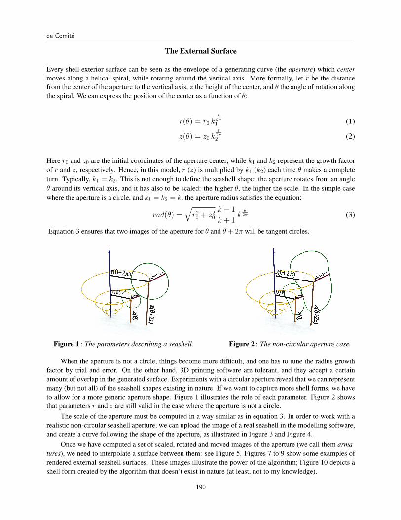
Figure 1 : The parameters describing a seashell. Figure 2 : The non-circular aperture case.
When the aperture is not a circle, things become more difficult, and one has to tune the radius growthfactor by trial and error. On the other hand, 3D printing software are tolerant, and they accept a certainamount of overlap in the generated surface. Experiments with a circular aperture reveal that we can representmany (but not all) of the seashell shapes existing in nature. If we want to capture more shell forms, we haveto allow for a more generic aperture shape. Figure 1 illustrates the role of each parameter. Figure 2 showsthat parameters r and z are still valid in the case where the aperture is not a circle.
The scale of the aperture must be computed in a way similar as in equation 3. In order to work with arealistic non-circular seashell aperture, we can upload the image of a real seashell in the modelling software,and create a curve following the shape of the aperture, as illustrated in Figure 3 and Figure 4.
Once we have computed a set of scaled, rotated and moved images of the aperture (we call them arma-tures), we need to interpolate a surface between them: see Figure 5. Figures 7 to 9 show some examples ofrendered external seashell surfaces. These images illustrate the power of the algorithm; Figure 10 depicts ashell form created by the algorithm that doesn’t exist in nature (at least, not to my knowledge).
de Comite
190

Figure 3 : Aperture for Olivia Porphyria. Figure 4 : Aperture for Bankivia Fasciata.
Figure 5 : A surface enveloping a set of armatures. Figure 6 : Triangles between armatures.
Making the External Surface 3D Printable and Colourable
At one stage or another in the process of defining an object to be 3D printed, we have to express it in the formof a set of elementary triangles, tiling the object as faithfully as possible to render a good approximation ofthe virtual object. In general, this transformation is done when sending the object to the 3D printer. But asI need to be able to define as precisely as possible the colour of each point of the shell, I have chosen tocompletely describe the shell in terms of triangles from the very beginning of the computation.
The construction of the shell consists of the following:
• Define N points on the aperture curve. Typically, N is chosen to be between 200 and 500.
• Compute M armatures Ai, i = 1 · · · ,M of the scaled and rotated aperture, for increasing values of θ.The value M can vary from 100 to 500 armatures per revolution, depending on the memory capacityof the computer.
• Between each couple of consecutive armatures Ai and Ai+1, connect points Ai[j], Ai[j + 1] andAi+1[j+1] to define a triangle, and the same with points Ai[j], Ai+1[j] and Ai+1[j+1]. Two adjacenttriangles (one from each family) form a non-planar quadrilateral that will be assigned a colour. Thisquadrilateral can be seen as a kind of pixel on the shell surface.
Figure 6 illustrates this construction. A surface defined with such a tiling of triangles is called a mesh.Tools exist to define meshes in several computer languages, for example Python (which is used as a scriptlanguage in Blender). This way, I keep the control of the position of each part of the surface, and I will beable to define the colour of any point of the shell (see below).
Modelling Seashells Shapes and Pigmentation Patterns: Experiments with3D Printing
191
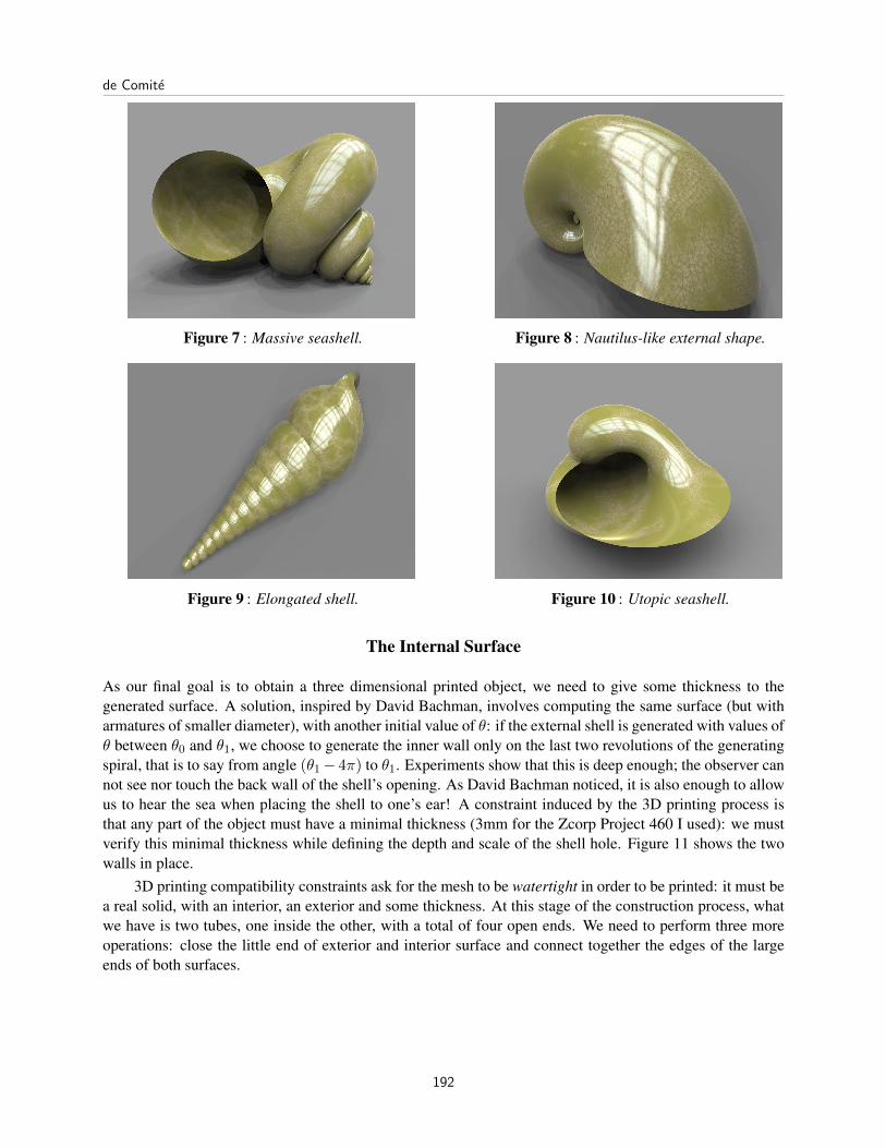
Figure 7 : Massive seashell. Figure 8 : Nautilus-like external shape.
Figure 9 : Elongated shell. Figure 10 : Utopic seashell.
The Internal Surface
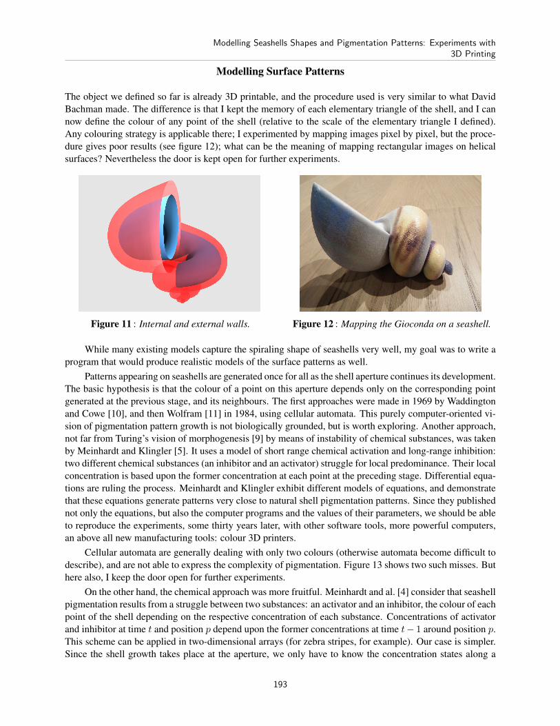
As our final goal is to obtain a three dimensional printed object, we need to give some thickness to thegenerated surface. A solution, inspired by David Bachman, involves computing the same surface (but witharmatures of smaller diameter), with another initial value of θ: if the external shell is generated with values ofθ between θ0 and θ1, we choose to generate the inner wall only on the last two revolutions of the generatingspiral, that is to say from angle (θ1− 4π) to θ1. Experiments show that this is deep enough; the observer cannot see nor touch the back wall of the shell’s opening. As David Bachman noticed, it is also enough to allowus to hear the sea when placing the shell to one’s ear! A constraint induced by the 3D printing process isthat any part of the object must have a minimal thickness (3mm for the Zcorp Project 460 I used): we mustverify this minimal thickness while defining the depth and scale of the shell hole. Figure 11 shows the twowalls in place.
3D printing compatibility constraints ask for the mesh to be watertight in order to be printed: it must bea real solid, with an interior, an exterior and some thickness. At this stage of the construction process, whatwe have is two tubes, one inside the other, with a total of four open ends. We need to perform three moreoperations: close the little end of exterior and interior surface and connect together the edges of the largeends of both surfaces.
de Comite
192
Modelling Surface Patterns
The object we defined so far is already 3D printable, and the procedure used is very similar to what DavidBachman made. The difference is that I kept the memory of each elementary triangle of the shell, and I cannow define the colour of any point of the shell (relative to the scale of the elementary triangle I defined).Any colouring strategy is applicable there; I experimented by mapping images pixel by pixel, but the proce-dure gives poor results (see figure 12); what can be the meaning of mapping rectangular images on helicalsurfaces? Nevertheless the door is kept open for further experiments.
Figure 11 : Internal and external walls. Figure 12 : Mapping the Gioconda on a seashell.
While many existing models capture the spiraling shape of seashells very well, my goal was to write aprogram that would produce realistic models of the surface patterns as well.
Patterns appearing on seashells are generated once for all as the shell aperture continues its development.The basic hypothesis is that the colour of a point on this aperture depends only on the corresponding pointgenerated at the previous stage, and its neighbours. The first approaches were made in 1969 by Waddingtonand Cowe [10], and then Wolfram [11] in 1984, using cellular automata. This purely computer-oriented vi-sion of pigmentation pattern growth is not biologically grounded, but is worth exploring. Another approach,not far from Turing’s vision of morphogenesis [9] by means of instability of chemical substances, was takenby Meinhardt and Klingler [5]. It uses a model of short range chemical activation and long-range inhibition:two different chemical substances (an inhibitor and an activator) struggle for local predominance. Their localconcentration is based upon the former concentration at each point at the preceding stage. Differential equa-tions are ruling the process. Meinhardt and Klingler exhibit different models of equations, and demonstratethat these equations generate patterns very close to natural shell pigmentation patterns. Since they publishednot only the equations, but also the computer programs and the values of their parameters, we should be ableto reproduce the experiments, some thirty years later, with other software tools, more powerful computers,an above all new manufacturing tools: colour 3D printers.
Cellular automata are generally dealing with only two colours (otherwise automata become difficult todescribe), and are not able to express the complexity of pigmentation. Figure 13 shows two such misses. Buthere also, I keep the door open for further experiments.
On the other hand, the chemical approach was more fruitful. Meinhardt and al. [4] consider that seashellpigmentation results from a struggle between two substances: an activator and an inhibitor, the colour of eachpoint of the shell depending on the respective concentration of each substance. Concentrations of activatorand inhibitor at time t and position p depend upon the former concentrations at time t− 1 around position p.This scheme can be applied in two-dimensional arrays (for zebra stripes, for example). Our case is simpler.Since the shell growth takes place at the aperture, we only have to know the concentration states along a
Modelling Seashells Shapes and Pigmentation Patterns: Experiments with3D Printing
193
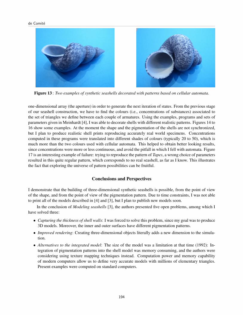
Figure 13 : Two examples of synthetic seashells decorated with patterns based on cellular automata.
one-dimensional array (the aperture) in order to generate the next iteration of states. From the previous stageof our seashell construction, we have to find the colours (i.e., concentrations of substances) associated tothe set of triangles we define between each couple of armatures. Using the examples, programs and sets ofparameters given in Meinhardt [4], I was able to decorate shells with different realistic patterns. Figures 14 to16 show some examples. At the moment the shape and the pigmentation of the shells are not synchronized,but I plan to produce realistic shell prints reproducing accurately real world specimens. Concentrationscomputed in these programs were translated into different shades of colours (typically 20 to 50), which ismuch more than the two colours used with cellular automata. This helped to obtain better looking results,since concentrations were more or less continuous, and avoid the pitfall in which I fell with automata. Figure17 is an interesting example of failure: trying to reproduce the pattern of Tapes, a wrong choice of parametersresulted in this quite regular pattern, which corresponds to no real seashell, as far as I know. This illustratesthe fact that exploring the universe of pattern possibilities can be fruitful.
Conclusions and Perspectives
I demonstrate that the building of three-dimensional synthetic seashells is possible, from the point of viewof the shape, and from the point of view of the pigmentation pattern. Due to time constraints, I was not ableto print all of the models described in [4] and [3], but I plan to publish new models soon.
In the conclusion of Modeling seashells [3], the authors presented five open problems, among which Ihave solved three:
• Capturing the thickness of shell walls: I was forced to solve this problem, since my goal was to produce3D models. Moreover, the inner and outer surfaces have different pigmentation patterns.
• Improved rendering: Creating three-dimensional objects literally adds a new dimension to the simula-tion.
• Alternatives to the integrated model: The size of the model was a limitation at that time (1992): In-tegration of pigmentation patterns into the shell model was memory consuming, and the authors wereconsidering using texture mapping techniques instead. Computation power and memory capabilityof modern computers allow us to define very accurate models with millions of elementary triangles.Present examples were computed on standard computers.
de Comite
194
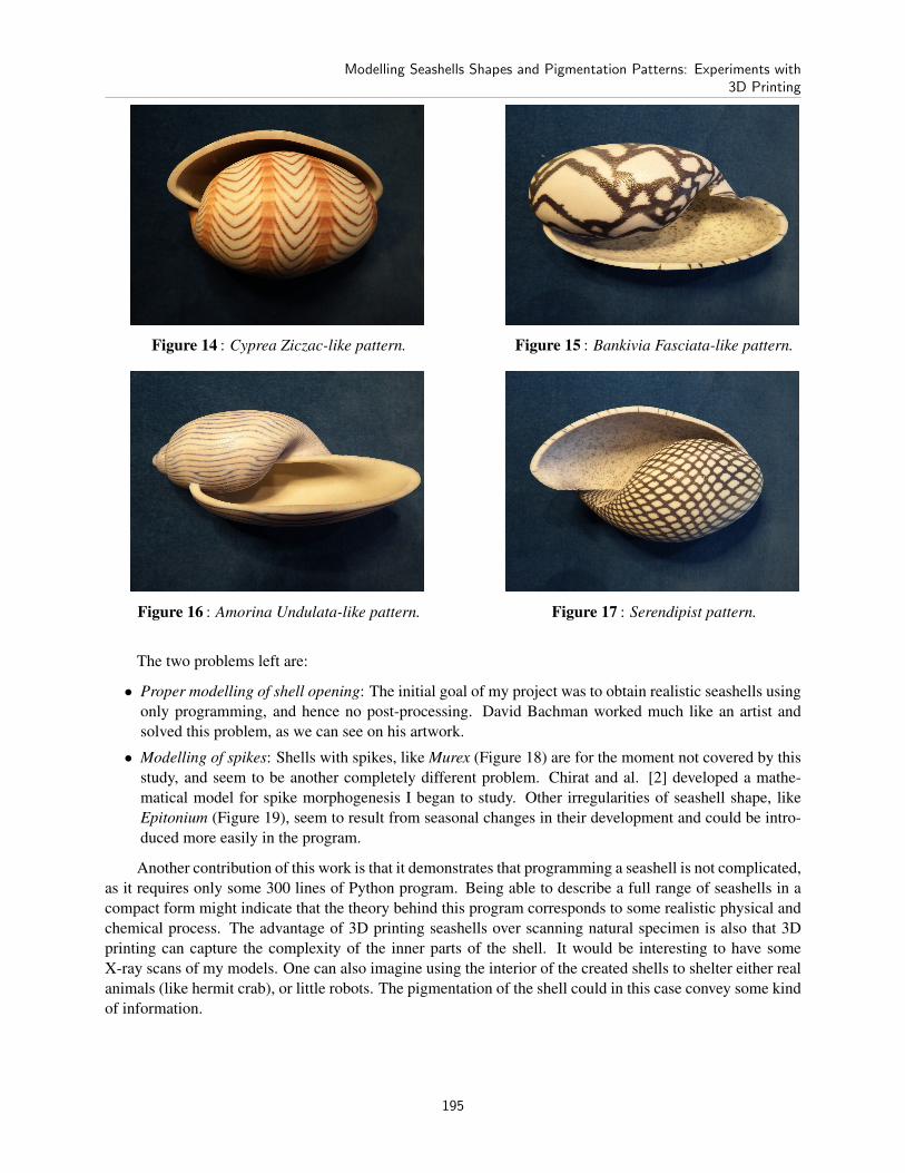
Figure 14 : Cyprea Ziczac-like pattern. Figure 15 : Bankivia Fasciata-like pattern.
Figure 16 : Amorina Undulata-like pattern. Figure 17 : Serendipist pattern.
The two problems left are:
• Proper modelling of shell opening: The initial goal of my project was to obtain realistic seashells usingonly programming, and hence no post-processing. David Bachman worked much like an artist andsolved this problem, as we can see on his artwork.
• Modelling of spikes: Shells with spikes, like Murex (Figure 18) are for the moment not covered by thisstudy, and seem to be another completely different problem. Chirat and al. [2] developed a mathe-matical model for spike morphogenesis I began to study. Other irregularities of seashell shape, likeEpitonium (Figure 19), seem to result from seasonal changes in their development and could be intro-duced more easily in the program.
Another contribution of this work is that it demonstrates that programming a seashell is not complicated,as it requires only some 300 lines of Python program. Being able to describe a full range of seashells in acompact form might indicate that the theory behind this program corresponds to some realistic physical andchemical process. The advantage of 3D printing seashells over scanning natural specimen is also that 3Dprinting can capture the complexity of the inner parts of the shell. It would be interesting to have someX-ray scans of my models. One can also imagine using the interior of the created shells to shelter either realanimals (like hermit crab), or little robots. The pigmentation of the shell could in this case convey some kindof information.
Modelling Seashells Shapes and Pigmentation Patterns: Experiments with3D Printing
195
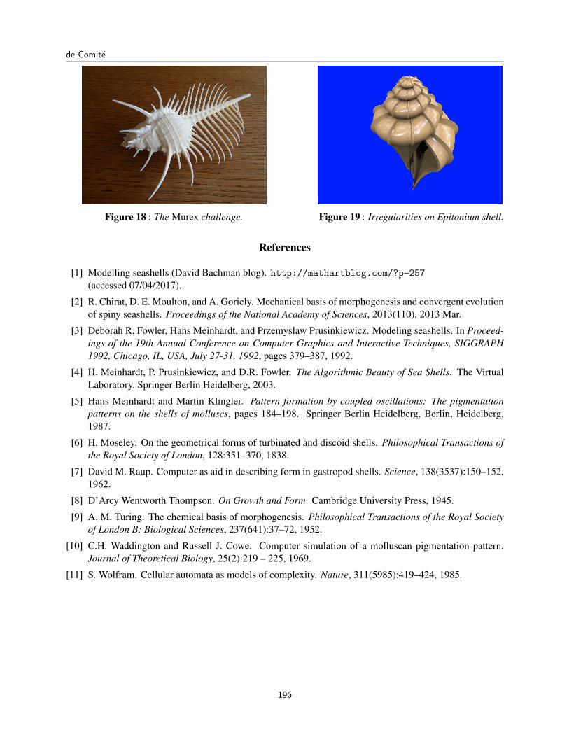
Figure 18 : The Murex challenge. Figure 19 : Irregularities on Epitonium shell.
References
[1] Modelling seashells (David Bachman blog). http://mathartblog.com/?p=257(accessed 07/04/2017).
[2] R. Chirat, D. E. Moulton, and A. Goriely. Mechanical basis of morphogenesis and convergent evolutionof spiny seashells. Proceedings of the National Academy of Sciences, 2013(110), 2013 Mar.
[3] Deborah R. Fowler, Hans Meinhardt, and Przemyslaw Prusinkiewicz. Modeling seashells. In Proceed-ings of the 19th Annual Conference on Computer Graphics and Interactive Techniques, SIGGRAPH1992, Chicago, IL, USA, July 27-31, 1992, pages 379–387, 1992.
[4] H. Meinhardt, P. Prusinkiewicz, and D.R. Fowler. The Algorithmic Beauty of Sea Shells. The VirtualLaboratory. Springer Berlin Heidelberg, 2003.
[5] Hans Meinhardt and Martin Klingler. Pattern formation by coupled oscillations: The pigmentationpatterns on the shells of molluscs, pages 184–198. Springer Berlin Heidelberg, Berlin, Heidelberg,1987.
[6] H. Moseley. On the geometrical forms of turbinated and discoid shells. Philosophical Transactions ofthe Royal Society of London, 128:351–370, 1838.
[7] David M. Raup. Computer as aid in describing form in gastropod shells. Science, 138(3537):150–152,1962.
[8] D’Arcy Wentworth Thompson. On Growth and Form. Cambridge University Press, 1945.
[9] A. M. Turing. The chemical basis of morphogenesis. Philosophical Transactions of the Royal Societyof London B: Biological Sciences, 237(641):37–72, 1952.
[10] C.H. Waddington and Russell J. Cowe. Computer simulation of a molluscan pigmentation pattern.Journal of Theoretical Biology, 25(2):219 – 225, 1969.
[11] S. Wolfram. Cellular automata as models of complexity. Nature, 311(5985):419–424, 1985.
de Comite
196