modelling rubber bushings using the parallel rheological...
TRANSCRIPT
2017 Science in the Age of Experience 1 http://www.3ds.com/events/science-in-the-age-of-experience
Modelling Rubber Bushings Using the Parallel Rheological Framework
Javier Rodríguez1, Francisco Riera1, and Jon Plaza2 1Principia, Spain; 2Cikatek, Spain
Abstract: Bushings are anti‐vibration components used in vehicle suspension systems. They are typically made of rubber between two concentric metallic cylinders. Their analysis requires characterising their complex impedance (dynamic stiffness and phase angle). Their behaviour is often difficult to predict without testing a prototype. The rubber undergoes large strains, usually involving strain stiffening and Mullins effect, time dependency and, possibly, plasticity. Thus the behaviour depends on the loading frequency and amplitude, as well as the preload. To tackle the problem a methodology has been developed that combines Abaqus and Isight. From the constitutive models in the material library the parallel rheological framework (PRF) is the most appropriate one for the rubber. It is based on a hyperelastic material model and consists of multiple parallel viscoelastic networks. The hyperelastic model is determined by evaluating strain energy potentials for a uniaxial quasi‐static tensile test; dynamic tests are used to calibrate the parameters of the PRF model. The process combines Abaqus analyses on a single element model with Isight runs for minimising the differences between test and model results. Based on this a model of the bushing is constructed and used for predicting its behaviour under static and dynamic loads, self‐contact, axial and radial displacements, and torsional and Cardanic rotations. The model takes into account the assembly loads produced by thermal shrinkage and a subsequent plastic reduction of the radius.
Keywords: Bushings, Rubber, Impedance, Parallel Rheological Framework (PRF), Material Calibration, Assembly Loads, Cyclic Tests.
1. Introduction
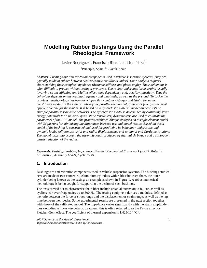
Bushings are anti‐vibration components used in vehicle suspension systems. The bushings studied here are made of two concentric Aluminium cylinders with rubber between them, the outer cylinder being known as the casing; an example is shown in Figure 1. A robust numerical methodology is being sought for supporting the design of such bushings. The tests carried out to characterise the rubber include uniaxial extension to failure, as well as cyclic shear over frequencies up to 500 Hz. The testing equipment derives a modulus, defined as the ratio between the force or stress range and the displacement or strain range, as well as the lag time between their peaks. Some experimental results are presented in the next section together with those of the calibrated model. The impedance varies significantly with the strain amplitude, thus excluding a linear viscoelastic treatment; this is often referred to as the Payne effect or Fletcher-Gent effect. The coefficient of thermal expansion is 1.425⋅10-4 ºC-1.
2 2017 Science in the Age of Experience http://www.3ds.com/events/science-in-the-age-of-experience
The initial state of stress of the bushing is the result of two operations: shrinkage from 180 ºC to 25 ºC, during which the Aluminium cylinders do not undergo imposed deformations and the rubber maintains perfect adhesion to them, followed by swaging, a process in which the diameter of the casing is plastically reduced, leaving the rubber in a state of radial compression.
Figure 1. Geometry of one of the designs
The tests are conducted to guarantee the strength under static loads (radial displacement, torsional rotation, and Cardan rotation), as well as in cyclic conditions to determine the stiffness over the frequency range of interest.
2. Material model
2.1 Long-term static behaviour
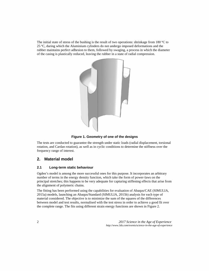
Ogden’s model is among the more successful ones for this purpose. It incorporates an arbitrary number of terms in the energy density function, which take the form of power-laws on the principal stretches; this happens to be very adequate for capturing stiffening effects that arise from the alignment of polymeric chains. The fitting has been performed using the capabilities for evaluation of Abaqus/CAE (SIMULIA, 2015a) models, launching an Abaqus/Standard (SIMULIA, 2015b) analysis for each type of material considered. The objective is to minimize the sum of the squares of the differences between model and test results, normalised with the test stress in order to achieve a good fit over the complete range. The fits using different strain energy functions are shown in Figure 2.
2017 Science in the Age of Experience 3 http://www.3ds.com/events/science-in-the-age-of-experience
Elastomers are usually taken to be incompressible, as their Poisson’s ratios are typically between 0.4995 and 0.4999. However, this assumption may prove inadequate in highly confined conditions, as developed in some of the bushings analysed.
Figure 2. Fits achieved using hyperelastic models
2.2 Viscoelastic behaviour The only Abaqus model that can capture the non-linear viscoelastic behaviour in elastomers is the parallel rheological framework (PRF). It is composed of a balance framework that describes the long-term response through a hyperelastic model, and an arbitrary number of viscoelastic frameworks that decompose the strain gradient in two factors, one elastic (left) and the other viscous (right). Various viscous models are supported, which control creep in each viscoelastic framework. The more appropriate model for describing the hysteretic phenomena of interest is Bergstrom-Boyce’s, which takes the following incremental form:
𝜀𝜀 ̅̇ = 𝐴𝐴(𝜆𝜆𝑐𝑐𝑐𝑐 − 1 + 𝐸𝐸)𝐶𝐶𝑞𝑞�𝑚𝑚 where
𝜆𝜆𝑐𝑐𝑐𝑐 = �13𝐈𝐈:𝐂𝐂𝑐𝑐𝑐𝑐,
with Ccr being the right Cauchy-Green tensor of the viscous part. Besides, the viscoelastic flow potential (describing the decomposition of the strain increment in the deformed configuration) is isotropic and the equivalent stress 𝑞𝑞� corresponds to the von Mises stress (associative flow). The
0
2
4
6
8
10
12
0.0 0.5 1.0 1.5 2.0 2.5 3.0 3.5 4.0
Nom
inal
stre
ss (M
Pa)
Nominal strain (-)
ExperimentalMooney-RivlinYeohOgden (N=2)Ogden (N=3)
4 2017 Science in the Age of Experience http://www.3ds.com/events/science-in-the-age-of-experience
viscous parameters are A, m, C and E, with a positive value of E being required to regularize the solution. The value proposed by the authors of the model, namely 0.01, has been maintained here. This viscous model is quite similar to one that Abaqus already had for elastomers (*HYSTERESIS). The main difference is that the PRF model allows several parallel frameworks rather than just one, a capability that is important here, as will be seen later. A model with a single viscoelastic framework is considered first. Since the long-term hyperelastic parameters have already been determined, the items missing are the stiffness ratio between the viscoelastic and balance frameworks, r1, and the Bergstrom-Boyce parameters (A, m and C). Moreover, to improve the quality of the results, an additional parameter s introduced, which scales the long-term Ogden moduli µ1 and µ2 of the material. An additional viscoelastic framework of negligible velocity will be introduced to handle force application times (A is small for this framework). This framework allows representing the asymptotic behaviour in low-frequency cyclic tests without interfering with the long-term response observed in static tests. The assembly loads will be determined using Abaqus’ capability for establishing the long-term equilibrium (parameter LONG TERM in *STATIC). The consistent modification of the stiffness ratios of the frameworks is explained later. The parameters are optimised independently for each frequency. In the model they will be modified via a field variable (temperature) in a manner consistent with the subsequent cyclic demands. For each amplitude and frequency, three cycles are performed, the first two with at least 40 increments and the last one with at least 96. Those numbers affect the quality of the results, particularly the lag time obtained as a difference between the times of the strain and stress peaks. A less computationally expensive procedure will be used for the global model. The objective function to be minimised for fitting the parameters is based on the square of the differences in modulus and phase angle between the model and the test, added over all the oscillation amplitudes. Different weighting factors are used for the modulus and the phase angle, trying to avoid results that are much better for one than for the other. The algorithm selected is the simplex downhill optimisation (unrelated with the simplex method in linear programming). The simplex points represent possible solutions to the problem. A simplex is a hypervolume in the n-dimensional design space defined by n + 1 nodes. The algorithm searches for the minimum of the objective function, following a number of operations in the simplex, such as reflection, expansion and contraction. It first locates the node where the function takes a maximum value and reflects it on the opposite phase of the simplex. It then evaluates the function at a number of points in the normal to that face through the new node. If the function takes a lower value at any of those points, it then replaces the node (expansion); otherwise the simplex is contracted in all directions with respect to the node with the minimum value and the algorithm is executed again. One of the advantages of the procedure is that it can be parallelised. Other methods, such as that by Hooke and Jeeves, are also very successful but less amenable to parallelisation. The algorithm is available in Isight (SIMULIA, 2015c), which was the program used to govern the optimisation process. A workflow was constructed which updates the parameters in the Abaqus’ input file, launches it, and executes the script that determines the error.
2017 Science in the Age of Experience 5 http://www.3ds.com/events/science-in-the-age-of-experience
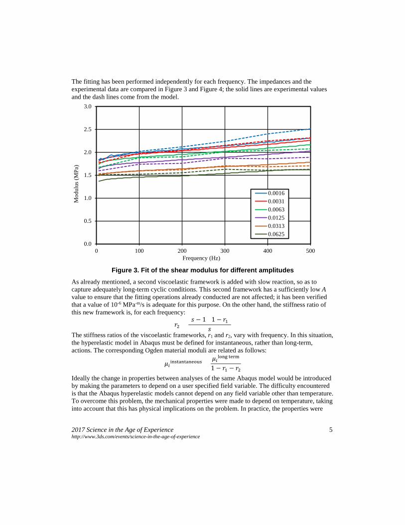
The fitting has been performed independently for each frequency. The impedances and the experimental data are compared in Figure 3 and Figure 4; the solid lines are experimental values and the dash lines come from the model.
Figure 3. Fit of the shear modulus for different amplitudes
As already mentioned, a second viscoelastic framework is added with slow reaction, so as to capture adequately long-term cyclic conditions. This second framework has a sufficiently low A value to ensure that the fitting operations already conducted are not affected; it has been verified that a value of 10-6 MPa-m/s is adequate for this purpose. On the other hand, the stiffness ratio of this new framework is, for each frequency:
𝑟𝑟2 =(𝑠𝑠 − 1)(1 − 𝑟𝑟1)
𝑠𝑠
The stiffness ratios of the viscoelastic frameworks, r1 and r2, vary with frequency. In this situation, the hyperelastic model in Abaqus must be defined for instantaneous, rather than long-term, actions. The corresponding Ogden material moduli are related as follows:
𝜇𝜇𝑖𝑖instantaneous =𝜇𝜇𝑖𝑖long term
1 − 𝑟𝑟1 − 𝑟𝑟2
Ideally the change in properties between analyses of the same Abaqus model would be introduced by making the parameters to depend on a user specified field variable. The difficulty encountered is that the Abaqus hyperelastic models cannot depend on any field variable other than temperature. To overcome this problem, the mechanical properties were made to depend on temperature, taking into account that this has physical implications on the problem. In practice, the properties were
0.0
0.5
1.0
1.5
2.0
2.5
3.0
0 100 200 300 400 500
Mod
ulus
(MPa
)
Frequency (Hz)
0.00160.00310.00630.01250.03130.0625
6 2017 Science in the Age of Experience http://www.3ds.com/events/science-in-the-age-of-experience
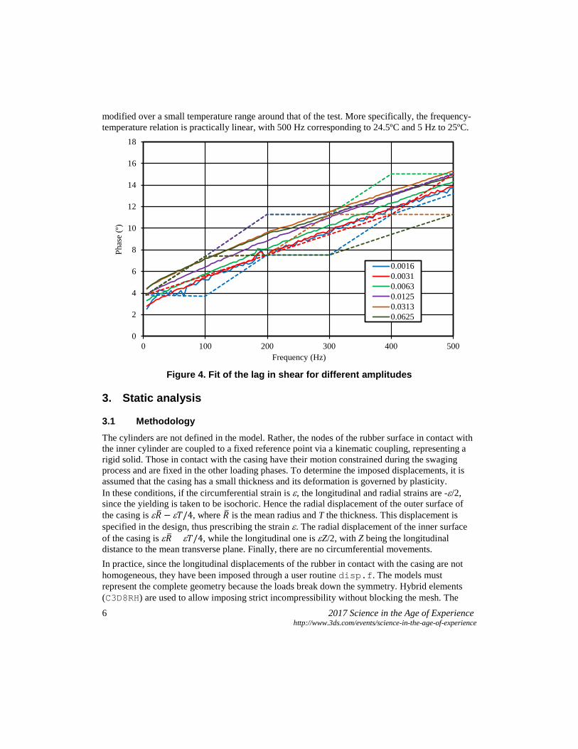
modified over a small temperature range around that of the test. More specifically, the frequency-temperature relation is practically linear, with 500 Hz corresponding to 24.5ºC and 5 Hz to 25ºC.
Figure 4. Fit of the lag in shear for different amplitudes
3. Static analysis
3.1 Methodology
The cylinders are not defined in the model. Rather, the nodes of the rubber surface in contact with the inner cylinder are coupled to a fixed reference point via a kinematic coupling, representing a rigid solid. Those in contact with the casing have their motion constrained during the swaging process and are fixed in the other loading phases. To determine the imposed displacements, it is assumed that the casing has a small thickness and its deformation is governed by plasticity. In these conditions, if the circumferential strain is ε, the longitudinal and radial strains are -ε/2, since the yielding is taken to be isochoric. Hence the radial displacement of the outer surface of the casing is ε𝑅𝑅� − ε𝑇𝑇/4, where 𝑅𝑅� is the mean radius and T the thickness. This displacement is specified in the design, thus prescribing the strain ε. The radial displacement of the inner surface of the casing is ε𝑅𝑅� + ε𝑇𝑇/4, while the longitudinal one is εZ/2, with Z being the longitudinal distance to the mean transverse plane. Finally, there are no circumferential movements. In practice, since the longitudinal displacements of the rubber in contact with the casing are not homogeneous, they have been imposed through a user routine disp.f. The models must represent the complete geometry because the loads break down the symmetry. Hybrid elements (C3D8RH) are used to allow imposing strict incompressibility without blocking the mesh. The
0
2
4
6
8
10
12
14
16
18
0 100 200 300 400 500
Phas
e (º
)
Frequency (Hz)
0.00160.00310.00630.01250.03130.0625
2017 Science in the Age of Experience 7 http://www.3ds.com/events/science-in-the-age-of-experience
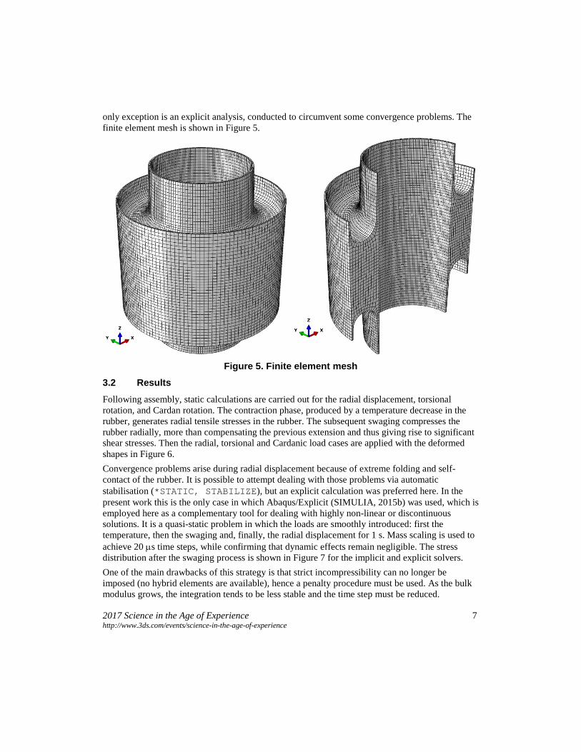
only exception is an explicit analysis, conducted to circumvent some convergence problems. The finite element mesh is shown in Figure 5.
Figure 5. Finite element mesh
3.2 Results
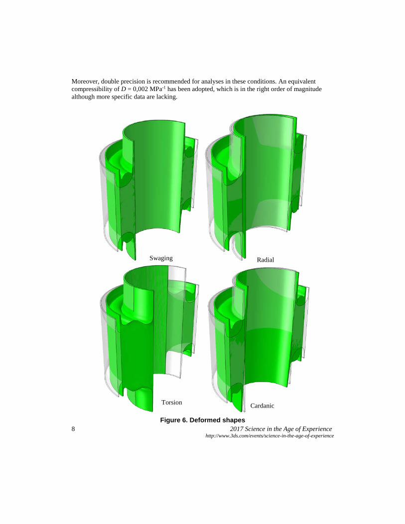
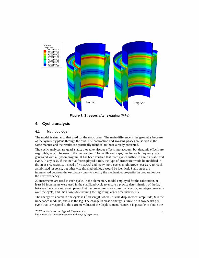
Following assembly, static calculations are carried out for the radial displacement, torsional rotation, and Cardan rotation. The contraction phase, produced by a temperature decrease in the rubber, generates radial tensile stresses in the rubber. The subsequent swaging compresses the rubber radially, more than compensating the previous extension and thus giving rise to significant shear stresses. Then the radial, torsional and Cardanic load cases are applied with the deformed shapes in Figure 6. Convergence problems arise during radial displacement because of extreme folding and self-contact of the rubber. It is possible to attempt dealing with those problems via automatic stabilisation (*STATIC, STABILIZE), but an explicit calculation was preferred here. In the present work this is the only case in which Abaqus/Explicit (SIMULIA, 2015b) was used, which is employed here as a complementary tool for dealing with highly non-linear or discontinuous solutions. It is a quasi-static problem in which the loads are smoothly introduced: first the temperature, then the swaging and, finally, the radial displacement for 1 s. Mass scaling is used to achieve 20 µs time steps, while confirming that dynamic effects remain negligible. The stress distribution after the swaging process is shown in Figure 7 for the implicit and explicit solvers. One of the main drawbacks of this strategy is that strict incompressibility can no longer be imposed (no hybrid elements are available), hence a penalty procedure must be used. As the bulk modulus grows, the integration tends to be less stable and the time step must be reduced.
8 2017 Science in the Age of Experience http://www.3ds.com/events/science-in-the-age-of-experience
Moreover, double precision is recommended for analyses in these conditions. An equivalent compressibility of D = 0,002 MPa-1 has been adopted, which is in the right order of magnitude although more specific data are lacking.
Figure 6. Deformed shapes
Swaging Radial
Torsion Cardanic
2017 Science in the Age of Experience 9 http://www.3ds.com/events/science-in-the-age-of-experience
Figure 7. Stresses after swaging (MPa)
4. Cyclic analysis
4.1 Methodology
The model is similar to that used for the static cases. The main difference is the geometry because of the symmetry plane through the axis. The contraction and swaging phases are solved in the same manner and the results are practically identical to those already presented. The cyclic analyses are quasi-static; they take viscous effects into account, but dynamic effects are negligible, as will be seen in the next section. The oscillatory steps, one for each frequency, are generated with a Python program. It has been verified that three cycles suffice to attain a stabilized cycle. In any case, if the inertial forces played a role, the type of procedure would be modified in the steps (*DYNAMIC instead of *VISCO) and many more cycles might prove necessary to reach a stabilized response, but otherwise the methodology would be identical. Static steps are interspersed between the oscillatory ones to modify the mechanical properties in preparation for the next frequency. 20 increments are used in each cycle. In the elementary model employed for the calibration, at least 96 increments were used in the stabilized cycle to ensure a precise determination of the lag between the stress and strain peaks. But the procedure is now based on energy, an integral measure over the cycle, and this allows determining the lag using larger time increments. The energy dissipated in one cycle is U2πKsen(ϕ), where U is the displacement amplitude, K is the impedance modulus, and ϕ is the lag. The change in elastic energy is UK/2, with two peaks per cycle that correspond to the extreme values of the displacement. Hence, it is possible to obtain the
Implicit Explicit
10 2017 Science in the Age of Experience http://www.3ds.com/events/science-in-the-age-of-experience
lag from the viscously dissipated energy once the stiffness has been determined through the relation between the force and displacement ranges in a cycle. This is not usually what a test machine measures, but is equivalent to recording the lag between peaks under harmonic forcing. The post-processing required to determine the impedance spectra is simplified by means of a Python program.
4.2 Initial results
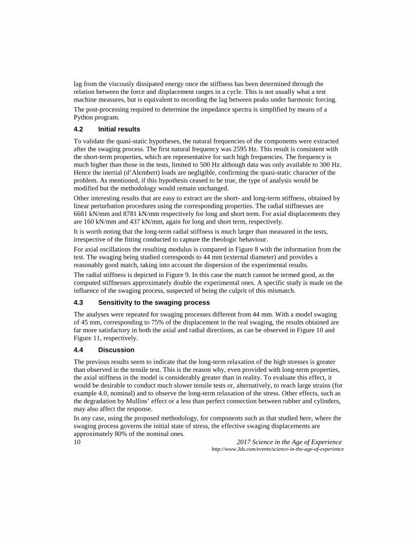
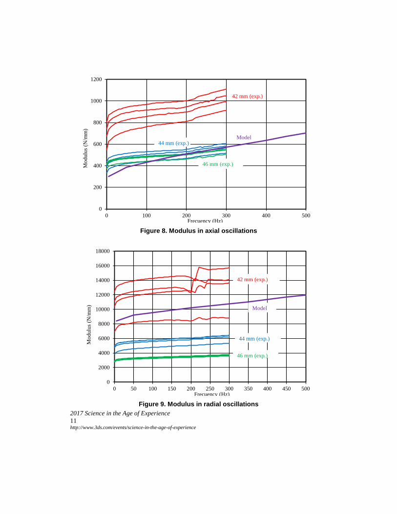
To validate the quasi-static hypotheses, the natural frequencies of the components were extracted after the swaging process. The first natural frequency was 2595 Hz. This result is consistent with the short-term properties, which are representative for such high frequencies. The frequency is much higher than those in the tests, limited to 500 Hz although data was only available to 300 Hz. Hence the inertial (d’Alembert) loads are negligible, confirming the quasi-static character of the problem. As mentioned, if this hypothesis ceased to be true, the type of analysis would be modified but the methodology would remain unchanged. Other interesting results that are easy to extract are the short- and long-term stiffness, obtained by linear perturbation procedures using the corresponding properties. The radial stiffnesses are 6681 kN/mm and 8781 kN/mm respectively for long and short term. For axial displacements they are 160 kN/mm and 437 kN/mm, again for long and short term, respectively. It is worth noting that the long-term radial stiffness is much larger than measured in the tests, irrespective of the fitting conducted to capture the rheologic behaviour. For axial oscillations the resulting modulus is compared in Figure 8 with the information from the test. The swaging being studied corresponds to 44 mm (external diameter) and provides a reasonably good match, taking into account the dispersion of the experimental results. The radial stiffness is depicted in Figure 9. In this case the match cannot be termed good, as the computed stiffnesses approximately double the experimental ones. A specific study is made on the influence of the swaging process, suspected of being the culprit of this mismatch.
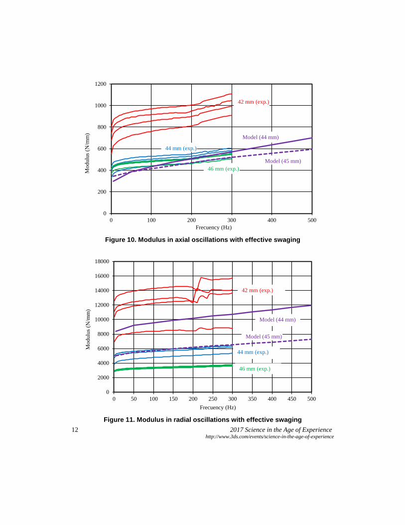
4.3 Sensitivity to the swaging process The analyses were repeated for swaging processes different from 44 mm. With a model swaging of 45 mm, corresponding to 75% of the displacement in the real swaging, the results obtained are far more satisfactory in both the axial and radial directions, as can be observed in Figure 10 and Figure 11, respectively.
4.4 Discussion The previous results seem to indicate that the long-term relaxation of the high stresses is greater than observed in the tensile test. This is the reason why, even provided with long-term properties, the axial stiffness in the model is considerably greater than in reality. To evaluate this effect, it would be desirable to conduct much slower tensile tests or, alternatively, to reach large strains (for example 4.0, nominal) and to observe the long-term relaxation of the stress. Other effects, such as the degradation by Mullins’ effect or a less than perfect connection between rubber and cylinders, may also affect the response. In any case, using the proposed methodology, for components such as that studied here, where the swaging process governs the initial state of stress, the effective swaging displacements are approximately 80% of the nominal ones.
2017 Science in the Age of Experience 11 http://www.3ds.com/events/science-in-the-age-of-experience
Figure 8. Modulus in axial oscillations
Figure 9. Modulus in radial oscillations
0
200
400
600
800
1000
1200
0 100 200 300 400 500
Mod
ulus
(N/m
m)
Frecuency (Hz)
42 mm (exp.)
44 mm (exp.)
46 mm (exp.)
Model
0
2000
4000
6000
8000
10000
12000
14000
16000
18000
0 50 100 150 200 250 300 350 400 450 500
Mod
ulus
(N/m
m)
Frecuency (Hz)
42 mm (exp.)
44 mm (exp.)
46 mm (exp.)
Model
12 2017 Science in the Age of Experience http://www.3ds.com/events/science-in-the-age-of-experience
Figure 10. Modulus in axial oscillations with effective swaging
Figure 11. Modulus in radial oscillations with effective swaging
0
200
400
600
800
1000
1200
0 100 200 300 400 500
Mod
ulus
(N/m
m)
Frecuency (Hz)
42 mm (exp.)
44 mm (exp.)
46 mm (exp.)
Model (44 mm)
Model (45 mm)
0
2000
4000
6000
8000
10000
12000
14000
16000
18000
0 50 100 150 200 250 300 350 400 450 500
Mod
ulus
(N/m
m)
Frecuency (Hz)
42 mm (exp.)
44 mm (exp.)
46 mm (exp.)
Model (44 mm)
Model (45 mm)
2017 Science in the Age of Experience 13 http://www.3ds.com/events/science-in-the-age-of-experience
5. Conclusions
As a result of the work performed, the following conclusions can be offered: a. The 3-term Ogden material, adjusted over the range of tensile strains up to 4.0 (nominal)
appears adequate for the present purposes. b. The compressibility of the rubber plays a negligible role in the stresses generated during
thermal contraction and swaging. This role may be more significant in static load cases, particularly in those involving radial displacements.
c. The tensile tests should be sufficiently slow to allow evaluating the change in behaviour. Alternatively, the imposed deformation should be large and the necessary information would then be obtained from the long-term relaxation of the stress.
d. The parallel rheological framework model with the Bergstrom-Boyce viscous behaviour allows capturing the non-linear viscoelasticity evinced in the cyclic tests. Besides the balance framework, two rheological frameworks are recommended. This allows representing the asymptotic behaviour in low-frequency cyclic tests without interfering with the long-term behaviour observed in static tests.
e. The fitting of the rheological parameters was done with Isight using the simplex downhill optimisation procedure. The fitting should be independent for each frequency. The parameters of the model are modified adequately for each cyclic load.
f. An implicit methodology is recommended (Abaqus/Standard). An explicit approach (Abaqus/Explicit) may be useful for dealing with the higher demands if convergence problems are triggered by the strong non-linearities caused by folding and self-contact. In this case the incompressibility is handled by penalty on the volumetric strains.
g. The behaviour of the bushing is highly dependent on the swaging and this sensitivity should be studied in more detail. With the available information and using the proposed methodology, an effective swaging could be that corresponding to 80% of the nominal displacements.
6. References
1. SIMULIA (2015a) “Abaqus/CAE User’s Guide”, version 2016. 2. SIMULIA (2015b) “Abaqus Analysis User’s Guide”, version 2016. 3. SIMULIA (2015c) “Isight User’s Guide”, version 2016.