modelling performance of ultracapacitor arrays in hybrid ... · modelling performance of...
TRANSCRIPT

Int. J. Alternative Propulsion, Vol. 1, No. 1, 2006
Copyright © 2006 Inderscience Enterprises Ltd.
32
Modelling performance of ultracapacitor arrays in hybrid electric vehicles
Robert G. Wiegers* 7815 W Quail Ln, Wichita, KS 67212, USA E-mail: [email protected] *Corresponding author
Donald M. Blackketter Department of Mechanical Engineering, University of Idaho, Moscow, Idaho 83844-0902, USA E-mail: [email protected]
Herbert L. Hess Department of Electrical Engineering, University of Idaho, Moscow, Idaho 83844-1023, USA E-mail: [email protected]
Abstract: This paper describes the development of a computer model to model performance of ultracapacitor arrays in hybrid electric vehicles. A Power-Based Model (PBM) was created and the results were compared with data from the University of Idaho’s ultracapacitor hybrid Future Truck. The PBM accurately predicts vehicle fuel economy and allows quick simulation speed. This model includes a derived Internal Combustion (IC) engine fuel map with interpolation function and a random capacitance generator for balancing circuit implementation. Experimental data showed that the Future Truck averaged 15.9 mpg operating non-hybrid whereas the PBM predicted 16.8 mpg for a non-hybrid set-up over the same drive cycle, a 5% difference. PBM as shown can accurately predict the vehicle performance including the added benefits from implementing an ultracapacitor array and balancing circuits. Using PBM, it is seen that ultracapacitors are a viable energy storage solution for hybrid electric vehicles.
Keywords: vehicle; modelling; hybrid vehicles; ultracapacitors; balancing circuits; engine modelling.
Reference to this paper should be made as follows: Wiegers, R.G., Blackketter, D.M. and Hess, H.L. (2006) ‘Modelling performance of ultracapacitor arrays in hybrid electric vehicles’, Int. J. Alternative Propulsion, Vol. 1, No. 1, pp.32–46.
Modelling performance of ultracapacitor arrays 33
Biographical notes: Robert G. Wiegers received an MS in Mechanical Engineering from the University of Idaho in 2004. He is currently working for Cessna Aircraft Company as a Design Engineer. His interests are in hybrid vehicle research and implementation, aircraft design and space vehicle development.
Donald M. Blackketter received his PhD from the University of Wyoming in 1989. Currently, he teaches mechanical engineering graduate and undergraduate courses in the areas of mechanics and vehicle design. For the past five years, he has served as the Director of the Center for Clean Vehicle Technology (CCVT), and currently is the Assistant Director of the National Institute for Advanced Transportation Technology (NIATT). In these roles, he oversees a number of vehicle projects, including addressing problems in combustion and air pollution and the production of energy from renewable fuels.
Herbert L. Hess received his PhD from the University of Wisconsin in 1993. He served on the Faculty of the US Military Academy from 1983 to 1988. He joined the University of Idaho in 1993, where he is currently an Associate Professor of Electrical and Computer Engineering. He is a Reserve Officer assigned as an electrical engineer to the US Army Research Laboratory, Adelphi, MA. He has developed power electronics for applications ranging from distributed generating stations to military and automotive applications to resource industries, such as forest and dairy products, down to complete systems having converters and load on a single chip.
1 Introduction
With the decrease of fossil fuel reserves, there is an increased demand for hybrid vehicles. Hybrid vehicles under development provide cheap, dependable and clean improvements in fuel economy. Essentially, all hybrid electric vehicles including fuel cell vehicles require energy storage systems, commonly battery packs. Problems exist with battery packs including the inability to absorb and discharge large current loads during regenerative braking and boost assist, performance degradation over their life, weight, size and environmental concerns regarding disposal. Ultracapacitors can eliminate these problems; this paper presents a model of ultracapacitor arrays as battery pack replacements.
Ultracapacitor arrays as the primary electrical storage are a new concept having several advantages over batteries. Ultracapacitors have a high cycle life in excess of 500,000 cycles; equivalent to the life of an average vehicle with no physical deterioration or performance degradation. Ultracapacitors, unlike batteries, can charge and discharge large current loads (in excess of 200 amps) experienced during hybrid vehicle operation without incurring damages. Disposal of ultracapacitors is less environmentally sensitive than batteries in that batteries are composed of metals in an acid whereas ultracapacitors are a metal foil submersed in a non-toxic electrolytic solution.
A better understanding of ultracapacitor array performance and system integration is required before ultracapacitors can replace batteries. The goal of this research is the development of a system model to accurately predict the overall hybrid electric vehicle performance.
34 R.G. Wiegers, D.M. Blackketter and H.L. Hess
2 Methods and procedures of the power-based model
This research was focused on creation of a Power-Based Model (PBM) of University of Idaho’s ultracapacitor parallel electric hybrid Future Truck (Wiegers and Blackketter, 2004). The Future Truck is Ford Explorer chassis with a 3.0L V6 engine, 5 speed automatic transmission and a 48 V AC motor. The chassis, rear differential, transmission and Internal Combustion (IC) engine were accurately modelled using vehicle specifications collected from (2001 Lincoln LS Workshop Manual, 2001; 2001 Ford Explorer Workshop Manual, 2001; 2001 Lincoln LS Specifications, 2004; 2001 Ford Explorer Specifications, 2004). The Future Truck was equipped with 80 2.5 V Maxwell 2700 F ultracapacitors in a 48 V array; these were arranged with 4 parallel strands of 20 ultracapacitors in series. This ultracapacitor array was modelled using Spyker and Nelm’s theory (Spyker and Nelms, 2000) with a voltage balancing circuit model included.
2.1 PBM: overview
PBM was programmed using a backwards looking power-based approach that calculates required torque and rpm at the tyres and traces these values through system components ending with the calculation of engine fuel economy (Markel et al., 2002; Wipke et al., 1999). Construction of PBM began with derivation of the road load equations and creation of a non-hybrid vehicle model. This model was modified by integrating the electrical system representation to create a hybrid vehicle model. Integration of the AC motor and controller was achieved using system efficiency data and a DC machine model for the terminal behaviour of the machine-electronic drive system. The ultracapacitor array was modelled using Spyker and Nelm’s model for ultracapacitors (Spyker and Nelms, 2000) and including effects of voltage balancing circuits to accurately predict performance. For an accurate model, control strategies were taken from the Future Truck controls and incorporated into the hybrid vehicle model.
2.2 Non-hybrid portion of vehicle model
2.2.1 Road load equations
Road load for the PBM included aerodynamic load, rolling resistance, wheel resistance to spinning, acceleration load and load due to road grade, (1), (2), (3), (4) and (5), respectively (Hibbeler, 1998; Shigley and Mischke, 2001).
2aero air
12µ ρ= iF Av (1)
rolling k cos( )µ θ=F mg (2)
wheels 4 α =
IFr
(3)
accel =F ma (4)
grade sin( )θ=F mg (5)
required total= iP F v (6)

Modelling performance of ultracapacitor arrays 35
Required power was calculated using (6), by summing road load and multiplying by vehicle velocity for a given time step. Power provided at the tyres was set equal to required power, with zero losses between the road and tyre. For a specific power and tyre angular velocity, required torque at the wheel can be calculated using (7) and (8) (Shigley and Mischke, 2001).
rotating τϖ= iP (7)
12
ϖπ
=i ivr (8)
Tracing the torque and angular velocity through vehicle systems, IC engine fuel consumption was derived using a fuel usage map.
2.2.2 Wheel slippage calculations
Accelerations the vehicle sustains according to drive cycle velocities may not be realistic compared to what the vehicles tyre grip is capable of handling. To determine if a tyre slips, (9) was used to calculate the tyres’ break-free torque (Hibbeler, 1998). If a tyre does slip, ‘Tire Slippage Occurring’ is outputted notifying the user that invalid results are possible.
slip12
τ µ α= +smg r I (9)
2.2.3 Transmission
The rear differential is the first gearing in the drive line followed by the transmission. The rear differential and transmission gear ratios were found in 2001 Ford Explorer Workshop Manual (2001). The transmission was modelled with a speed-dependent shifting strategy. As engine load varies with the magnitude of acceleration, different shift strategies were written dependent on the acceleration magnitude (Table 1).
Table 1 Transmission speed-dependent shift strategy for Lincoln LS Automatic 5 spd
Gear shift (mph) Acceleration (m/s) 1–2 2–3 3–4 4–5
a < 0.5 15 21 34 43
0.5 < a < = 2.0 19 27 38 46
2.0 < a 24 33 43 58
Owing to the variability of engine torque, the effects of shifting on a grade were not modelled.
2.2.4 Internal combustion engine
Fuel usage of IC engines is dependent on torque and rpm they produce. For the creation of PBM, a similar method to (Rizzoni et al., 1999) was used. A general engine performance map for a naturally aspirated standard performance engine (Figure 1) was used (Heywood, 1988).

36 R.G. Wiegers, D.M. Blackketter and H.L. Hess
Figure 1 Brake-specific fuel consumption graph for naturally aspirated standard performance 4 stroke IC engine (Heywood, 1988)
Discrete values were gathered from Figure 1 along with engine bore, stroke and displacement (2001 Lincoln LS Workshop Manual, 2001). These values relate Brake Mean Effective Pressure (BMEP) to torque, Mean Piston Speed (MPS) to engine rpm and Brake Specific Fuel Consumption (BSFC) to mass flow rate of fuel using (10), (11), (12) and (13) (Heywood, 1988) and create an engine-specific fuel map (Figure 2).
Figure 2 Lincoln LS 3.0L spark ignition 4-Stroke IC engine fuel map showing fuel consumption for 19 different torques and 14 different rpm
engine
2
2BMEP rn
Vπτ
= (10)
MPS 2LN= (11)
engine2πτ•
=bW N (12)
•
•= f
b
mBSFCW
(13)

Modelling performance of ultracapacitor arrays 37
For the model to accurately utilise the derived engine-specific fuel map, an interpolating function was implemented to estimate fuel usage between discrete points. Summing the fuel consumption and dividing by the total distance, the average vehicle fuel economy was calculated.
2.3 Hybrid system portion of vehicle model
The Future Truck’s transfer case couples the electric motor and drive shaft with a 1:1 gear ratio. System efficiency gains come from torque being added to and taken from the drive shaft by the electric motor. To model the amount of torque going to and coming from the hybrid systems control strategies and limits were implemented in PBM.
For an accurate representation of the ultracapacitor array, Spyker and Nelm’s model for ultracapacitors was used (Spyker and Nelms, 2000). Using basic circuit analysis and ultracapacitor capacitance and resistance, they contend that (14) is viable when time steps are kept small.
CapCap
∆=
∆V
I Ct
(14)
Results and comparisons with real world data prove the simple representation accurate; experimental energy load was within 5% of modelled (Spyker and Nelms, 2000). This theory was for the ultracapacitor array model with inputs being initial voltage and current solving for final voltage after a one second time step.
2.3.1 Hybrid control strategies
To regulate regenerative braking and boost assist, control strategies were integrated into the motor, controller and ultracapacitor array models. For an accurate representation of the Future Truck’s control strategies, Jeremy Forbes was consulted (Forbes, Private Communication).
The regenerative braking control strategy is dependent on the vehicle speed and controls the percentage of torque being used by the electric motor (Figure 3).
Figure 3 Electric hybrid regenerative braking control strategy dependent on vehicle speed and solving for percentage of drive shaft torque the hybrid is using
38 R.G. Wiegers, D.M. Blackketter and H.L. Hess
At speeds higher than 72 mph the vehicle’s friction brakes absorb 75% of the drive shaft torque while the hybrid system uses 25% of the drive shaft torque. Between 72 mph and 22 mph there are two lines representing percentage regenerative braking ending at 100% for speeds less than 22 mph (Figure 3). At these lower speeds, the hybrid system uses 100% of the drive shaft torque for regenerative braking and the friction brakes do nothing. For boost assist the control strategy is similar to the regenerative braking control strategy.
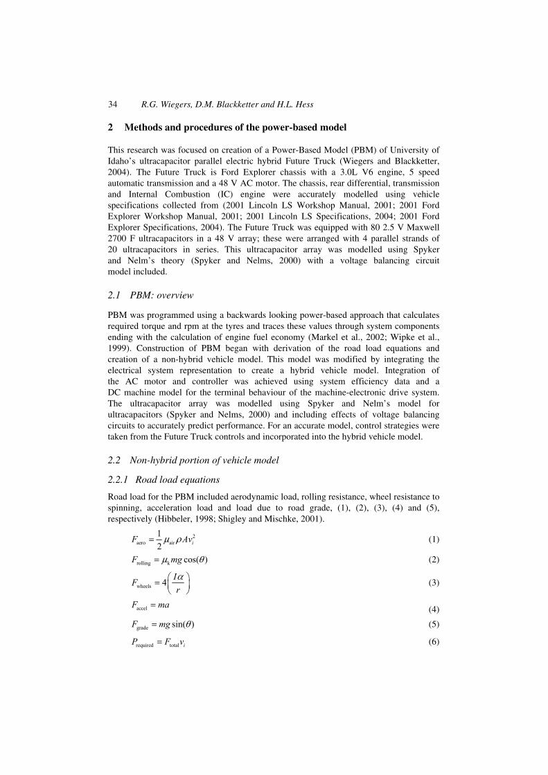
The boost assist strategy, shown in Figure 4, is dependent on the vehicle speed and controls current discharge based on the percentage of the ultracapacitors arrays maximum current discharge.
Figure 4 Electric hybrid boost assist control strategy dependent on vehicle speed and solving for the percentage of maximum current discharge of the ultracapacitor array
At speeds less than 22 mph, the control strategy allows for 100% of the maximum current to be discharged. A linear relationship between 22 mph and 45 mph determines ultracapacitor array current discharge. The control strategy levels off at speeds higher than 45 mph and allows 10% of the maximum current to be discharged in these points. For these control strategies to work correctly, ultracapacitor array performance limits were implemented.
In addition to regenerative braking and boost assist control strategies, the hybrid system had limits implemented. These include the motor limited to producing and the ultracapacitor array limited to discharging 250 amps or less for protection of the electrical components, the electric motor being limited to producing 80.1 ft-lbs of torque (Hi Performance Golf Cars, 2004) and the 2.5 V ultracapacitor cells being limited to 2.4 V for compliance with the 48 V hybrid vehicle’s low voltage regulations. These limits and control strategies regulate the torque and current the system produces.
2.3.2 Motor controller modelling
A DC model was used to combine AC motor and controller into one model using the system efficiency to account for losses. System efficiency values were gathered from testing done in Hi Performance Golf Cars (2004) with the missing points assumed according to typical AC motor performance (Solectria AC 90 – C&D, 2004). The controller efficiency was taken as a constant 95% while the motor efficiency varies (Figure 5).

Modelling performance of ultracapacitor arrays 39
Figure 5 Motor efficiency of the Future Truck’s 48 V AC induction machine, dependent on the shaft rpm using data from (Solectria AC 90 – C&D, 2004)
The motor rpm is equal to the drive shaft and the motor voltage is the same as the ultracapacitor array. The current and output torque was calculated during regenerative braking and boost assist respectively by setting (15) and (16) equal and multiplying by the system efficiency (Irwin and Wu, 1999; Shigley and Mischke, 2001).
mechanical motor motorτ ϖ=P (15)
electrical motor=P VI (16)
2.3.3 Ultracapacitor array modelling
Properties of the ultracapacitor array were defined by user inputs and vehicle characteristics. A uniform random number generator was used to produce cell capacitances falling within manufacturing tolerances of ±10% creating the need for voltage balancing circuit implementation (BOOSTCAP Integration Kit, 2004). Array capacitance was calculated using equations for capacitors in series and parallel. Ultracapacitor cell voltages, 2.4 V, were added according to Kirchhoff’s Voltage Law to find total ultracapacitor array voltage. The vehicle modelled had 20 cells in series and four of these strings in parallel creating a 48 V array. Ultracapacitors have the potential to discharge to zero volts but, stated by Jeremy Forbes, are limited to 36 V on the Future Truck and this is reflected in PBM (Forbes, Private Communication). To maintain repeatability for simulation, ultracapacitor initial voltage was assumed to be at 40 V. Knowing the array properties, voltage after each time step was calculated.
During regenerative braking, the ultracapacitor arrays initial voltage is known from the previous time step, the current is determined by the control strategy and motor effects, and voltage per time step can be calculated using (14) (Spyker and Nelms, 2000). For boost assist the discharge current, regulated by the control strategy, the ultracapacitor array initial voltage, and (14) is used to calculate final voltage.
Knowing the current, voltage and angular velocity, a DC motor model of terminal behaviour calculates motor torque. This torque was subtracted from the torque required at the drive shaft during boost assist. With the lower torque requirement, the IC engine

40 R.G. Wiegers, D.M. Blackketter and H.L. Hess
requires less fuel to meet the torque requirement at the wheels. Tracing this torque through the transmission and using the derived IC engine fuel map, hybrid fuel economy was calculated.
2.3.4 Ultracapacitor balancing circuit
Uses and types of balancing circuits are described in Barrade et al. (2000) along with diagrams showing how the circuit is wired. Need for balancing circuits is described by Maxwell Electronics as variation in manufacturing of the ultracapacitor cells causes cells to have different capacitances (Cell Balancing in Low Duty Cycle Applications, 2004). This variation in cell capacitance is represented in PBM by a random capacitance generator. For an accurate representation of ultracapacitor cell voltage, balancing circuit models were implemented in the hybrid system model. The balancing circuits used on the Future Truck’s ultracapacitor array were Maxwell Boostcap Integration Kits (2004). These circuit boards are considered active balancing circuits and have specific current drain characteristics, ±300 mA discharging and charging per board (BOOSTCAP Integration Kit, 2004). To model the balancing circuit effects, voltage in each cell was calculated using Kirchhoff’s Voltage and Current Laws combined with (14). The balancing current for each cell was based on a linear relationship between minimum and maximum voltage and the mean voltage of one ultracapacitor string. Two linear Equations (17) and (18) were derived using the slopes from the average voltage to the maximum and minimum voltages with the extremes being ±300 mA and the average having zero current.
( )balance cell mean cell meanmin mean
300 for = − ≤−
I V V V VV V
(17)
( )balance cell mean cell meanmax mean
300 for −= − ≤−
I V V V VV V
(18)
For each cell in the array Equations (17) and (18) were used to calculate the balancing circuit. Equation (14), initial voltages and balancing circuit current were used to derive the balanced voltage of each cell. The effects of implementing the balancing circuit was seen by calculating the power lost, (19).
balance balance cell∆ = ∆P I V (19)
2.4 Vehicle system efficiency
To compare the performance of hybrid and non-hybrid vehicles, the total vehicle efficiency was evaluated. To calculate this efficiency, Equation (20) divides energy needed to propel the vehicle through each time step by the total energy released from combusting the quantity of fuel the IC engine consumes.
road
fuelconsumed
Eff 100=E
E (20)
Modelling performance of ultracapacitor arrays 41
The energy needed to propel the vehicle was calculated using (21), and the energy released by combustion of the fuel was calculated by (22).
road total=E F d (21)
fuelconsumed fuel fuel fuelρ=E V HV (22)
An increase in this efficiency should be evident from vehicle hybridisation because of regenerative braking and boost assist.
3 Results and discussion
The result of this investigation was a Matlab program capable of modelling performance of an ultracapacitor array-based hybrid electric vehicle. Experimental data collected from the University of Idaho’s Future Truck was used for comparison of modelled results. The results of integrating a random capacitance generator and voltage balancing circuit were investigated and discussed.
3.1 Motor and controller representation
The DC model representation worked well for modelling the motor and controller combination. With the implementation of the variable system efficiency, there was a minor drop in fuel efficiency, approximately 0.2 mpg over the UDDS. A larger effect was seen from implementing the torque limit on the motor, this dropped the fuel efficiency by approximately 1 mpg. This verifies that a DC model for the terminal behaviour of the motor-power electric drive system was sufficiently accurate, therefore, a more detailed modelling of the AC motor and drive system became unnecessary.
3.2 Voltage balancing circuit
Voltage balancing circuits have little literature published on their workings and implementation; papers have been written on different balancing strategies and technical specification sheets can be found but they are of little help when modelling performance (Barrade et al., 2000; Cell Balancing in Low Duty Cycle Applications, 2004). The balancing strategy in PBM incorporated an active balancing current capability and circuit resistance. PBM’s results proved to be representative of the modelled system. From implementing the active balancing circuit, there was a power loss of approximately 0.5 Watts and a decrease in fuel economy of approximately 0.2 mpg. This is a small change in fuel economy but creates an accurate representation of ultracapacitor array performance. With implementation of the active balancing circuit, the effects of a random capacitance generator can be seen.
Owing to the nature of the random capacitance generator, the ultracapacitor array capacitance changes for every run. Over the course of twenty runs of the UDDS drive cycle, the standard deviation of the fuel economy was 0.0033 mpg. This shows that the fuel economy does change with each run but not enough to distort PBM’s results.
42 R.G. Wiegers, D.M. Blackketter and H.L. Hess
3.3 PBM versus experimental data results
By using a power-based method, PBM calculated torque and rpm of the wheels over the drive cycle, the maximum of these values were calculated and compared to what the IC engine is capable of producing. For the vehicle to match the UDDS drive cycle, the IC engine was required to produce, at maximum, 205.05 ft-lbs of torque and 2878.6 rpm. This is within the IC engines capabilities, as noted on the Lincoln LS information sheet the max torque capacity is 220 ft-lbs and 6400 rpm (2001 Ford Explorer Workshop Manual, 2001). The IC engines calculated fuel map proved to be an accurate representation of the modelled system. PBM modelled the non-hybrid vehicle fuel economy at 17.7 mpg and 21.5 mpg for hybrid fuel economy, a 21.5% increase in fuel economy over the UDDS. The overall vehicle system efficiencies were found to be 7.9% and 9.9% for the non-hybrid and hybrid vehicles, respectively.
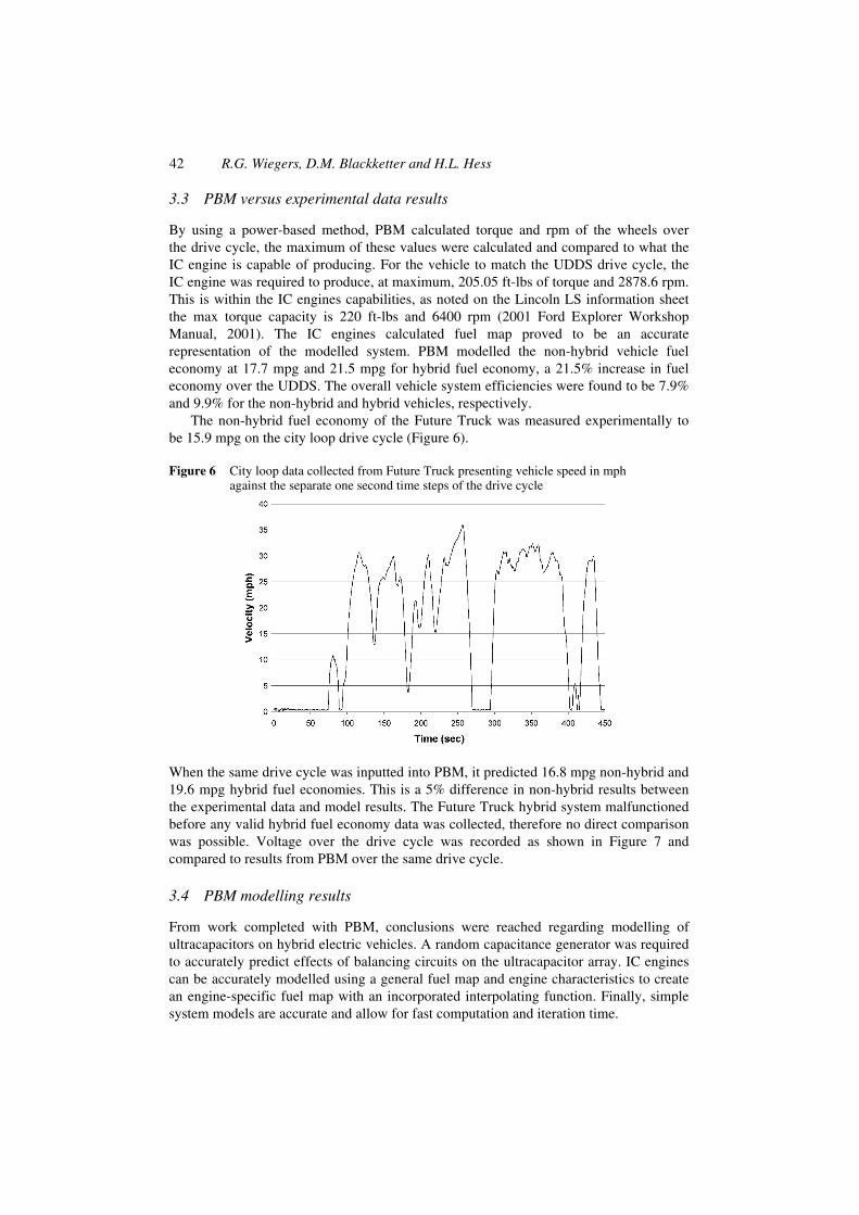
The non-hybrid fuel economy of the Future Truck was measured experimentally to be 15.9 mpg on the city loop drive cycle (Figure 6).
Figure 6 City loop data collected from Future Truck presenting vehicle speed in mph against the separate one second time steps of the drive cycle
When the same drive cycle was inputted into PBM, it predicted 16.8 mpg non-hybrid and 19.6 mpg hybrid fuel economies. This is a 5% difference in non-hybrid results between the experimental data and model results. The Future Truck hybrid system malfunctioned before any valid hybrid fuel economy data was collected, therefore no direct comparison was possible. Voltage over the drive cycle was recorded as shown in Figure 7 and compared to results from PBM over the same drive cycle.
3.4 PBM modelling results
From work completed with PBM, conclusions were reached regarding modelling of ultracapacitors on hybrid electric vehicles. A random capacitance generator was required to accurately predict effects of balancing circuits on the ultracapacitor array. IC engines can be accurately modelled using a general fuel map and engine characteristics to create an engine-specific fuel map with an incorporated interpolating function. Finally, simple system models are accurate and allow for fast computation and iteration time.

Modelling performance of ultracapacitor arrays 43
Figure 7 Voltage data recorded from testing of the Future Truck and results from PBM over the drive cycle
Discrepancies between PBM’s results and experimental data (Figure 7) came from different sources. The IC engine fuel usage map being derived from a general brake-specific fuel consumption map did not take into account unknown characteristics of the engine. To create a more accurate representation, the engine would have to undergo dynamometer testing to create an exact engine-specific fuel map. Along these same lines, assumptions for the transmission performance lead to variance in results. If the modelled transmission shifts at different points than the vehicle, engine torque and rpm are different as well and dissimilar fuel usage values will result in altered fuel economy predictions.
4 Conclusions
To create an accurate ultracapacitor hybrid model, physical and performance parameters for the IC engine such as displacement, torque and rpm as well as characteristics of the ultracapacitor array need to be included. It was shown that using a DC representation for the combined motor and controller system allowed for a simple and quick representation of the system. By implementing a random capacitance generator for the ultracapacitor cell capacitances, the effects of balancing circuit use along with the importance of cell capacitance tolerances was seen.
By utilising an ultracapacitor hybrid model, the increase in fuel economy from implementation of an ultracapacitor array was distinguished. The current loads that are seen during the drive cycles are in excess of what batteries are capable of handling but fall within the operating parameters of an ultracapacitor array. Ultracapacitors are more reliable in that they do not degrade over their life of 500,000+ cycles. It is clear that there are distinct advantages to using an ultracapacitor array instead of a battery pack for a hybrid vehicle energy storage system.

44 R.G. Wiegers, D.M. Blackketter and H.L. Hess
References
2001 Ford Explorer Specifications (2004) Available at: http://www.new-cars.com/2001/ford/ford-explorer-specifications.html. Accessed on 19 February.
Ford Motor Company. (2001) 2001 Ford Explorer Workshop Manual.
2001 Lincoln LS Specifications (2004) Available at: http://www.new-cars.com/2001/lincoln/ lincoln-ls-specification.html. Accessed on 19 February.
Ford Motor Company. (2001) 2001 Lincoln LS Workshop Manual.
Barrade, P., Pitttet, S. and Rufer, A. (2000) ‘Energy storage system using a series connection of supercapacitors, with an active device for equalizing the voltages’, Presented at the International Power Electronics Conference, Tokyo, Japan.
BOOSTCAP Integration Kit (2004) Available at: http://www.maxwell.com/ultracapacitors/ products/integration_kit.html. Accessed on 16 July.
Burke, A. (2000) ‘Ultracapacitors: why, how, and where is the technology’, Journal of Power Sources, Vol. 91, pp.37–50.
Cell Balancing in Low Duty Cycle Applications (2004) Available at: http://www.maxwell.com/ ultracapacitors/support/app_notes/cell_balancing.html. Accessed on 16 July.
Forbes, Jeremy. Personal Interview. 17 Feb. 2004.
Heywood, J.B. (1988) Internal Combustion Engine Fundamentals, New York: McGraw Hill, Inc., p.839.
Hi Performance Golf Cars (2004) Available at: http://www.hiperformancegolfcars.com. Accessed on 15 March.
Hibbeler, R. (1998) Engineering Mechanics Statics and Dynamics, New Jersey: Prentice-Hall.
Irwin, J. and Wu, C. (1999) Basic Engineering Circuit Analysis, New Jersey: Prentice-Hall, pp.251–281.
Markel, T., Brooker, A., Hendricks, T., Johnson, V., Kelly, K., Kramer, B., O’Keefe, M., Sprik, S. and Wipke, K. (2002) ‘ADVISOR: a systems analysis tool for advanced vehicle modelling’, Journal of Power Sources, Vol. 110, pp.255–266.
PC 2500 Ultracapacitor Product Information (2004) Available at: http://www.maxwell.com/ ultracapacitors/products/PC2500.html. Accessed on 8 March.
Rizzoni, G., Guzzella, L. and Baumann, B. (1999) ‘Unified modelling of hybrid electric vehicle drivetrains’, IEEE/ASME Transactions in Mechatronics, September, Vol. 4, pp.246–257.
Shigley, J. and Mischke, C. (2001) Mechanical Engineering Design, Boston: McGraw Hill, p.124.
Solectria AC 90 – C&D. (2004) Available at: http://www.solectria.com/downloads/ac90candd.pdf. Accessed on 29 November.
Spyker, R. and Nelms, R. (2000) ‘Optimization of double-layer capacitor arrays’, IEEE Transactions on Industry Applications, January/February, Vol. 36, pp.194–198.
Wiegers, R. and Blackketter, D. (2004) ‘Modelling performance of ultracapacitor arrays in hybrid electric vehicles’, Master of Science Thesis, University of Idaho, December.
Wipke, K., Cuddy, M. and Burch, S. (1999) ‘ADVISOR 2.1: a user-friendly advanced powertrain simulation using a combined backward/forward approach’, IEEE Transactions on Vehicular Technology, November, Vol. 48, pp.1751–1761.
Nomenclature
Unit g Gram hr Hour
m Meters

Modelling performance of ultracapacitor arrays 45
rad Radian
rev Revolution
s Seconds
A Ampere
F Farad
J Joule
N Newton
Pa Pascal
V Volt
W Watt
A Frontal area of vehicle m2
a Vehicle acceleration m s−2
BMEP Brake mean effective pressure Pa
BSFC Brake specific fuel consumption g (kW hr)−1
C Capacitance of ultracapacitor array F
Cn Number of ultracapacitors F
Cseries Series capacitance F
CparallelParallel capacitance F
d Distance per time step m
Eff Efficiency of vehicle system %
Efuelconsumed Energy of fuel consumed J
Eroad Energy to move vehicle J
Faccel Force to accelerate N
Faero Force due to aerodynamics N
Fgrade Force due to the grade of the road N
Frolling Torque and rpm force N
Ftotal Total road load force N
FwheelsForce to spin wheels N
g Acceleration due to gravity m s−2
HVfuelHeating value of the fuel J kg−1
I Rotational inertia of wheel kg m2
IbalanceCurrent to balance A
ICap Ultracapacitor current A
Imotor Motor current A
L Engine stroke m
MPS Mean piston speed m s−1
m Mass of the vehicle kg

46 R.G. Wiegers, D.M. Blackketter and H.L. Hess
N Engine speed rev s−1
nr Rev/power stroke (nr = 2)
PbalanceVoltage balancing power loss W
Pelectrical Electrical power W
Pmechanical Mechanical power W
Prequired Power required of move vehicle W
ProtatingPower of rotating object W
r Radius of Tyre m
rpm Rotational velocity rev min−1
V Motor voltage V
Vcell Ultracapacitor cell voltage V
Vmax Maximum voltage V
Vmin Minimum voltage V
Vs Swept volume of engine m3
vi Initial velocity m s−1
Vfuel Volume of fuel (PBM) m3
α Angular acceleration of tyre rad s−2
∆t Time step s
∆VCap Change in ultracapacitor voltage V
∆Vcell Change in voltage V
mdotb Mass flow of fuel kg s−1
Wdotb Brake work W
τ Torque N m
τengine Engine Torque N m
τmotor Motor Torque N m
τslip Torque limit N m
µair Airs coefficient of friction
µk Kinetic coefficient of friction
µs Static coefficient of friction
ρ Air density kg m−3
ρfuel Fuel density kg m−3
ωi Initial rotational velocity of wheel rad s−1
ωmotor Rotational velocity of motor rad s−1
θ Grade of drive cycle rad