modelling an unprotected loss-of-flow accident in …web.usm.my/jps/26-2-15/26-2-7.pdfmodelling an...
TRANSCRIPT

Journal of Physical Science, Vol. 26(2), 73–87, 2015
© Penerbit Universiti Sains Malaysia, 2015
Modelling an Unprotected Loss-of-Flow Accident in Research Reactors using the Eureka-2/Rr Code
Badrun Nahar Hamid,1* Md. Altaf Hossen,1 Sheikh Md. Tazul Islam2 and Rupia Begum2
1Reactor Physics and Engineering Division, Institute of Nuclear Science and Technology,
Atomic Energy Research Establishment, Ganakbari, Savar, Dhaka-1349, Bangladesh 2Department of Physics, Government B M College, Barisal, Bangladesh
*Corresponding author: [email protected]
Abstract: The main purpose of reactor safety is not to permit any release of radioactivity from the reactor core to the environment. To ensure reactor safety, the reactor must have sufficient margins during normal operation as well as in all possible accidental events, such as reactivity-induced accidents (RIAs), loss-of-coolant accidents (LOCAs), loss-of-flow accidents (LOFAs), etc. This study focuses on LOFA analysis of research reactors with the aim of investigating the impact of an unprotected LOFA on reactor safety. Two different research reactors, one a rod-type reactor with a cylindrical flow channel and another a plate-type reactor with rectangular flow channels, are taken as references for modelling LOFAs in coupled point kinetics, neutronics and thermal hydraulics code EUREKA-2/RR. Initially, LOFAs under protected conditions were simulated for both reactors. Major parameters such as fuel cladding temperature and bulk coolant temperature are evaluated to investigate whether these parameters exceed their safety limit or if any nucleate boiling occurs in the bulk coolant. For a protected LOFA, these parameters are found to remain within their design limit, and the reactor is sufficiently safe. In the case of an unprotected LOFA, although the Training Research and Isotope Production, General Atomics (TRIGA) reactor was found to be safe from the viewpoint of nucleate boiling not occuring in the bulk coolant, both reactors were found to be unsafe because the maximum cladding temperatures for both reactors are above the melting point in the course of an unprotected LOFA. Keywords: Unprotected LOFA, EUREKA-2/RR, reactor Safety 1. INTRODUCTION
The safe utilisation of nuclear reactors needs to be ensured due to the association of the reactors with hazardous radioactive isotopes and the vast amount of heat generated from the nuclear fission reaction. Although modern research reactors are designed with all safety features, various unusual events such as a reactivity initiated accident (RIA), a loss-of-flow accident (LOFA), or a loss-of-coolant accident (LOCA) can happen, and this type of event can cause a power excursion in the reactor core even though the heat transport system remains in perfect operating order. These serious events must be addressed as a

74 Modelling an Unprotected LOFA of Research Reactors
part of the safety analysis of nuclear reactors because if the power rises beyond the limits of the control system, reactor core damage with the release of large amounts of fission products could result. Due to this concern, this paper emphasises LOFA simulation with the aim of investigating reactor safety, especially during the course of an unprotected LOFA.
A LOFA occurs in a reactor due to many causes, such as loss of off-site power, pump failure, heat exchanger blockage, pipe blockage, valve closure, etc. The danger of a LOFA is that it could lessen fuel integrity due to overheating that arises from a low heat transfer coefficient in the reactor core. As a LOFA is classified by regulatory bodies as a design-based accident, necessary precautions need to be taken during the design stage to ensure that the primary coolant system has adequate safety margins against the onset of flow instability and departure from nucleate boiling to prevent a LOFA. With the exponential growth of computational codes in solving thermal hydraulics and transient problems, LOFA simulations have received much attention to date. It is customary to systematically consider the LOFA transient with and without a scram event, called, protected and unprotected or self-limited transients, respectively. However, most of the research reported so far is in the context of protected transients. Unprotected transient LOFA analysis, in contrast, has received very limited attention or is just beginning to attract attention. Therefore, the reactor operators may overlook data on reactor power and cladding temperature response in the case of an unprotected LOFA.
The rod-type TRIGA Mark-II research reactor of Bangladesh and the
plate type IEA-R1 reactor belonging to Brazil are considered references to analyse the present LOFA simulation using EUREKA-2/RR code.1 However, although protected LOFA transients for both of these reactors were reported earlier,2,3 a LOFA simulation of the IEA-R1 reactor using EUREKA-2/RR code is new. No analysis regarding uncontrolled LOFA has so far been reported for either of these reactors. 2. BOILING HEAT TRANSFER MECHANISM AND SAFETY
CRITERIA
During operation, the heat transfer rate from the fuel to the coolant is strongly involved with the boiling mechanism of the reactor water. If the variation of heat flux on the heated surface is recorded versus the surface-water temperature difference, as in Figure 1,4 the curve can be divided into four different regions. As long as the heated surface of the fuel remains below the coolant saturation temperature, only single-phase heat transfer will occur. After single-phase convection occurs in region I, in region II, subcooled (or local)

Journal of Physical Science, Vol. 26(2), 73–87, 2015 75
boiling occurs as the bulk coolant temperature remains below the coolant saturation temperature, but the heated fuel surface exceeds the saturation temperature. Region II could be called the nucleate boiling region as a vapour bubble forms at the heated surface that could eventually propagate into the coolant. If the temperature of the bulk coolant in this region exceeds the coolant saturation temperature, boiling in this region could be regarded as saturated nucleate boiling. Successively, the maximum flux attained when the bubbles become so dense that they coalesce forms a vapour film over the heated surface, resulting in the heat not being able to pass through the vapour film. Consequently, the heat flux decreases appreciably despite an increase in temperature. This maximum flux is considered a design limitation, which is referred to as the DNB (departure from nucleate boiling). Hence, starting with onset of nucleate boiling (ONB), region II develops a Departure from Nucleate Boiling Ratio (DNBR). The conditions in regions III and IV become so severe that may result damage to the material being heated may result. However, before arriving at these regions, a minimum DNBR value must be imposed as a part of the thermal hydraulic design.
Figure 1: Heat transfer through different regions of boiling coolant.
In regard to this boiling mechanism, two major safety criteria are usually set up for the thermal hydraulic design of research reactors so that fuel plates may have a sufficient safety margin during normal operation. These safety criteria are the following: (1) no nucleate boiling is allowed anywhere in the coolant and (2)
Hea
t fl
ux
Wall superheat satwallsat TTT −=∆
Non-boiling
Nucleate boiling
Departure from Nucleate Boiling (DNB)
Critical heat flux (CHF)
Onset of nucleate boiling (ONB)
Stable film boilingTransition
boiling
Heate
d sur
face
Heate
d sur
face
Heate
d sur
face
Heate
d sur
face
Heate
d sur
face
Heate
d sur
face
Heate
d sur
face
Heate
d sur
face
Rapid temperature rise
II I III IV

76 Modelling an Unprotected LOFA of Research Reactors
a minimum value needs to be set up for the departure from nucleate boiling (DNB). The present study is limited to focusing on two parameters, fuel cladding and bulk coolant temperatures, and based on these safety criteria, there is interest in whether these parameters remain within their design limit or whether the design limit leads to any boiling in the primary coolant system during the course of an unprotected LOFA. Table 1 presents the design limits imposed on these parameters during design-based accidents for both TRIGA and IEA-R1 reactors. Table 1: Design limit values of cladding and coolant of IEA-R1 and TRIGA reactors.
Parameters IEA-R1 TRIGA Mark-II Cladding temperature, °C 95 500
Coolant temperature, °C < 112 (saturation) < 113(saturation)
3. THERMAL HYDRAULIC DESIGN OF IEA-R1 REACTOR
Table 2 and Table 3 contain the geometry with hydraulic specifications and neutronics of the IEA-R1 reactor, obtained while the authors were involved with IEA-R1 research reactor calculations in a coordinated research project (CRP) of the International Atomic Energy Agency (IAEA) entitled "Innovative Methods in Research Reactor Analysis: Benchmark against Experimental Data" during the 2008–2012 period.5 At this time, an opportunity to use the specifications for the IEA-R1 reactor to conduct research from the viewpoint of the present context was taken. The IEA-R1 reactor of Brazil is a 5 MW pool type and plate type light water cooled and moderated. The graphite- and beryllium-reflected research reactor uses MTR fuel elements. The reactor contains 20 standard fuel elements, four control fuel elements and a central irradiator, assembled in a square matrix 5 × 5. Each standard fuel element has 18 fuel plates assembled on two lateral support plates, forming 17 independent rectangular flow channels. The control fuel element contains 12 plates, as there are two dummy lateral plates and two guide channels for the control plates. Figure 2 shows the arrangement of the fuel elements, the beryllium reflector, the control rods and the irradiated positions inside the reactor core. Figure 3 shows the simplified schematic of the reactor cooling system that consists of primary and secondary loops. During the continuous operation of the reactor at high power levels, the nuclear heat generated can be permitted to flow through the following auxiliary systems:
1. During the reactor operation, the forced circulation coolant system
pumps pool water down through the fuel elements to remove the fission heat from the reactor.

Journal of Physical Science, Vol. 26(2), 73–87, 2015 77
2. A water-to-water heat exchanger transfers the generated heat to a secondary water coolant system, and the primary water is returned to the reactor pool.
3. The secondary water carries heated water to the cooling tower which dissipates the heat to the atmosphere. Water from the cooling tower is recirculated through the secondary system.
Table 2: Descriptions of design parameters of IEA-R1 research reactor.
Table 3: Neutronic parameters of IEA-R1 research reactor.
Coefficient Values Average fuel temperature coefficient for 20–100°C –1.91 pcm/°C Average moderator temperature coefficient for 20–80°C –12.26 pcm/°C Average moderator density coefficient for 20–80°C –10.42 pcm/°C Average void coefficient 0–2.7% –231.92 pcm/% void
Effective delayed neutron factor (βeff) 0.00763
Reactor parameter Data Steady state power level (MW) 5 Fuel enrichment 20% Number of fuel element in the core 24
(1) Standard fuel element 20 (2) Control fuel element 4
Fuel type U3O8 –Al Maximum inlet temperature (°C) 40
Temperature difference between inlet and outlet (°C) 5.8 Number of fuel plates in:
(1) Standard Fuel Element 18 (2) Control Fuel Element 12
Thickness of the plates (mm) (1) Fuel 0.76 (2) Clad 0.38 (3) Total Thickness 1.52
Total width of the plates (mm) 67.1 Fuel meat dimensions (mm) 0.76 × 62.6 × 600 Thickness of water channel (mm) 2.89 Inlet pressure 1.7 bar Average velocity of coolant (m/s) 1.6

78 Modelling an Unprotected LOFA of Research Reactors
Figure 2: Core configuration of IEA-R1 research reactor.
Figure 3: Cooling system of IEA-R1 research reactor.
3.1 Sequence of the LOFA Accident of IEA-R1 Reactor
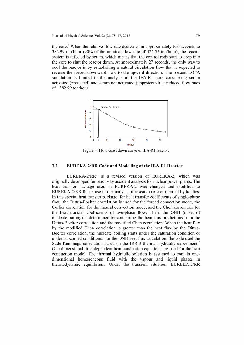
The cause of the LOFA established here is due to the loss of the pump energy supply, which eventually causes all primary pumps to trip. As a result, flow coast down will occur with loss of the flow rate through the core. Figure 4 shows the flow coast down curve as a time variation of the relative flow rate in
Journal of Physical Science, Vol. 26(2), 73–87, 2015 79
the core.5 When the relative flow rate decreases in approximately two seconds to 382.99 ton/hour (90% of the nominal flow rate of 425.55 ton/hour), the reactor system is affected by scram, which means that the control rods start to drop into the core to shut the reactor down. At approximately 27 seconds, the only way to cool the reactor is by establishing a natural circulation flow that is expected to reverse the forced downward flow to the upward direction. The present LOFA simulation is limited to the analysis of the IEA-R1 core considering scram activated (protected) and scram not activated (unprotected) at reduced flow rates of ~382.99 ton/hour.
Figure 4: Flow coast down curve of IEA-R1 reactor.
3.2 EUREKA-2/RR Code and Modelling of the IEA-R1 Reactor
EUREKA-2/RR3 is a revised version of EUREKA-2, which was originally developed for reactivity accident analysis for nuclear power plants. The heat transfer package used in EUREKA-2 was changed and modified to EUREKA-2/RR for its use in the analysis of research reactor thermal hydraulics. In this special heat transfer package, for heat transfer coefficients of single-phase flow, the Dittus-Boelter correlation is used for the forced convection mode, the Collier correlation for the natural convection mode, and the Chen correlation for the heat transfer coefficients of two-phase flow. Then, the ONB (onset of nucleate boiling) is determined by comparing the hear flux predictions from the Dittus-Boelter correlation and the modified Chen correlation. When the heat flux by the modified Chen correlation is greater than the heat flux by the Dittus-Boelter correlation, the nucleate boiling starts under the saturation condition or under subcooled conditions. For the DNB heat flux calculation, the code used the Sudo-Kaminaga correlation based on the JRR-3 thermal hydraulic experiment.3 One-dimensional time-dependent heat conduction equations are used for the heat conduction model. The thermal hydraulic solution is assumed to contain one-dimensional homogeneous fluid with the vapour and liquid phases in thermodynamic equilibrium. Under the transient situation, EUREKA-2/RR

80 Modelling an Unprotected LOFA of Research Reactors
performs the simulation considering the movement of various parameters such as the movement of the control rods, the insertion of reactivity, the loss of flow, etc.
Kaminaga6 developed three utility codes to produce the entire set of input data for EUREKA-2/RR, which are DISSUE, ICETEA and PREDISCO. DISSUE calculates power fraction and void, as well as Doppler, cladding expansion and coolant temperature reactivity weighting factors for each heat slab based on core neutronics calculations. ICETEA calculates coolant temperature distribution, and PREDISCO calculates pressure distributions in the coolant.
For modelling the IEA-R1 core in EUREKA-2/RR code, only fuel
regions with an upper and a lower plenum were considered. The whole core was divided into five distinct channels with each channel consisting of 10 heat slabs with 10 nodes, as shown in Figure 4. The model in total then consists of 52 nodes, 50 heat slabs and 56 junctions. According to Figure 5, Junction no. 56 is the fill junction used to simulate the primary coolant flow in the core. An extensive data table as a function of time was constructed to simulate the core flow rate during the loss of flow. These fill data were derived from the primary coolant flow coast down curve presented in Figure 3, as discussed above. Using the specifications of Table 2 and Table 3 and approximating some parameters, such as friction and resistance coefficients as well as fuel and cladding thermal properties due to the unavailability of data, the simulation was carried out, considering the scram delay time to be long.
Figure 5: Schematic diagram of the model prepared for EUREKA-2/RR analysis.

Journal of Physical Science, Vol. 26(2), 73–87, 2015 81
3.3 LOFA Simulation of IEA-R1 Core 3.3.1 Steady state thermal hydraulic analysis
The objective of thermal hydraulic analysis is to ensure the operational temperature in the core does not exceed the design limit of temperature. If it can be ensured the hottest channel exhibits the temperature below the core design limit, the remaining channels then will presumably fall within this limit. Hence, particular attention in this research has been paid on the hottest channel to ensure its temperature remains below the design limit.
Before proceed with the transient simulation by EUREKA-2/RR code,
another thermal hydraulic code, COOLOD-N27, has been used for steady state analysis of IEA-R1 reactor. The intention was to verify the steady state results of EUREKA-2/RR with that of COOLOD-N2 code. Using the specifications described in Table 2 and Table 3, fuel temperature, cladding temperature and coolant temperature obtained both from COOLOD-N2 and EUREKA-2/RR codes have been compared whereas in comparisons steady state results reported previously using the MERSAT3 code were taken into account. Based on this comparison, EUREKA-2/RR, COOLOD-N2 and MERSAT codes provide in Figure 6 the maximum fuel temperature in the hottest channel as 86.81, 83.21 and 86°C, respectively, in Figure 7 the corresponding maximum cladding temperature as 80.23, 80.39 and 76°C, respectively and in Figure 8 the maximum temperature in coolant as 53.45, 53.98 and 53.6°C, respectively. It is seen from these Figures that the results of EUREKA-2/RR are consistent with the results of other two codes which indicates accuracy in modelling of reactor core in the EUREKA-2/RR code. Again, the average cooling temperature increase from 40 to 44.9°C across the core computed by EUREKA-2/RR amounts an average heating rate of cooling as 5°C which is also found to be agreed well with the experimentally measured heating rate of 5°C. This additional comparison provides further confidence about the validity of the model developed in EUREKA-2/RR code that intend the authors to employ the EUREKA-2/RR code for the analyses of RIA and LOFA as described in the next section. Provided the cladding temperature is important to safety, change in cladding temperature has only been taken into discussion through the entire analysis. Accordingly, peak cladding temperature evaluated here during steady state analysis is found to remain well below the design limit temperature of 95°C.

82 Modelling an Unprotected LOFA of Research Reactors
Figure 6: Transient of reactor parameters of IEA-R1 reactor during protected LOFA.
Figure 7: Transient of cladding and coolant temperature of IEA-R1 reactor during unprotected LOFA.
Scram Set Point

Journal of Physical Science, Vol. 26(2), 73–87, 2015 83
Figure 8: Transient of cladding and coolant temperature of TRIGA reactor during
protected LOFA.
Although EUREKA-2/RR is proven to be a trusted code, before performing the transient analysis, the code was verified in modelling the IEA-R1 core by comparing the prediction of the EUREKA-2/RR code with another well-known thermal hydraulic code, COOLOD-N2,7 under steady state conditions. The steady state thermal hydraulic calculations for the IEA-R1 core were carried out under forced convection cooling at the rated thermal power of 5 MW. Fuel temperature, cladding temperature, and coolant temperature were calculated, and these calculations were verified against the calculations of the COOLOD-N2 code for the same rated thermal power of 5 MW. All the analytical results are provided in Table 4, and the calculations of EUREKA-2/RR agree well with the results of COOLOD-N2. Again, the average cooling temperature increases from 40 to 45°C across the core computed by EUREKA-2/RR amounts to an average heating rate for cooling as 5°C,5 which is also found to agree reasonably well with the experimentally measured heating rate of 5.8°C, which provides further confidence in the validity of the model developed in EUREKA-2/RR.
Table 4: Analysis results of IEA-R1 core at rated thermal power of 5MW.
Hottest channel EUREKA-2/RR COOLOD-N2 Fuel central temperature, °C 86.81 84.21
Cladding Temperature, °C 80.23 80.39
Coolant Temperature, °C 53.45 53.98

84 Modelling an Unprotected LOFA of Research Reactors
3.3.2 Simulation of protected LOFA transient
As a consequence of pump failure and a rapid decrease in the coolant flow rate, the core flow rate reaches the scram set point approximately 2.0 sec after the accident begins. Due to the scram being affected at 2.0 sec, the reactor gets the power down from its operational power of 5 MW at 2.0 sec, as reported in Figure 6. The maximum cladding temperature is reported as 83.34°C with the maximum coolant temperature of 54.73°C during the LOFA transition. As both cladding and coolant temperature remain below their melting point as well as below the coolant saturation temperature, 112°C, no boiling is predicted in the bulk coolant, indicating that the IEA-R1 reactor core is safe against the protected LOFA. 3.3.3 Simulation of unprotected LOFA transient
Figure 7 shows the variation of cladding and coolant temperatures with respect to coolant saturation temperature due to the unprotected LOFA. The figure illustrates that the cladding temperature increases and exceeds its melting temperature, 95°C, at approximately 10 seconds, which eventually rises above the coolant saturation temperature of 112°C at approximately 11.47 seconds. However, as the coolant temperature remains far below its saturation temperature, no boiling appears until this transient period. However, a continuing increase in cladding temperature during the progress of transient results in the increase of the coolant temperature and at 26.46 seconds, the coolant temperature seems to exceed the coolant saturation temperature, which led to the formation of a bubble in the coolant. Based on the safety criteria, the reactor seems unsafe at 10 seconds of the transient as the cladding temperature lies beyond its melting point. Additionally, the bubble formation at 26.46 seconds in the bulk coolant indicates that the IEA-R1 reactor could not remain on the safe side during the course of an unprotected LOFA. 4. LOFA ANALYSIS OF TRIGA MARK-II REACTOR
A detailed description of the geometry with the neutronics specifications and also the kinetic parameters of the studied TRIGA Mark-II reactor with its modelling in the EUREKA-2/RR code is introduced in my published work.2 This investigation is therefore a complementary study on reactor behaviours against an unprotected LOFA. However, although the transient of cladding and coolant temperature against the protected LOFA is illustrated in the earlier work, based on the present interest in the research area, whether these cladding and coolant temperatures exceed the coolant saturation temperature is clarified before proceeding with the unprotected LOFA.
Journal of Physical Science, Vol. 26(2), 73–87, 2015 85
4.1 Simulation of Protected LOFA Transient
Due to the consequences of pump failure and rapid decrease in the coolant flow rate during an LOFA, the core flow rate reaches the scram set point of 529.51 ton/hour, 85% of the normal flow rate of 622.96 ton/hour, 4.08 seconds after the accident begins, but due to the scram delay time of 0.015 s, the reactor scram takes place at 4.1 seconds after the accident begins, which causes the reactor power to decrease from its operational power of 3 MW at 4.1 seconds. As a result, the cladding temperature and the bulk coolant temperature will stop increasing due to the shutdown of the reactor. Figure 8 shows the cladding and coolant temperature together with the coolant saturation temperature, 113°C. The data are recorded here up to 40 seconds of transient, and both cladding and coolant temperatures are reported to remain below not only their melting point but also far below the coolant saturation temperature over the transient period, which in turn infers that there is no possibility of boiling in the coolant, and the reactor is safe in the protected LOFA condition. 4.2 Simulation of Unprotected LOFA Transient
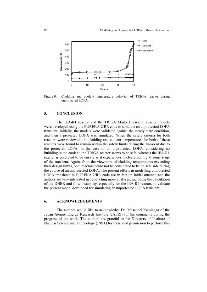
Based on the reactor scram system failing to shut the reactor down at an 85% loss-of-coolant nominal flow rate in the primary coolant, Figure 9 illustrates the variation of cladding and bulk coolant temperatures with respect to the coolant saturation temperature until 40 seconds of transient. In this unprotected situation, the cladding temperature increases gradually up to 30 s, after which the cladding temperature follows a sharp increase and exceeds its design limit of 500°C within a very short time. Such a fast transient heat transfer rate from cladding to coolant is too low to cause the coolant temperature to increase significantly from its initial values. Over the transient period, the coolant temperature attained a maximum value of approximately 61°C at 36 seconds. Hence, although the cladding temperature in some instants may exceed the design limit, the coolant temperature is observed to be far below the coolant saturation temperature, 113°C, and, consequently, no nucleate boiling is predicted during the unprotected LOFA. Another explanation of coolant temperature failure to increase with the increase of cladding temperature seems to be the feedback from the coefficients of reactivity. Although the cladding temperature increases rapidly due to its good conductivity, the prompt negative temperature coefficient of reactivity of the TRIGA reactor and the large value of the void coefficient of reactivity seem to suppress the reactor, so that the reactor operates with a low reactivity, which causes the coolant temperature not to increase with the increase in cladding temperature.
86 Modelling an Unprotected LOFA of Research Reactors
Figure 9: Cladding and coolant temperature behavior of TRIGA reactor during
unprotected LOFA. 5. CONCLUSION
The IEA-R1 reactor and the TRIGA Mark-II research reactor models were developed using the EUREKA-2/RR code to simulate an unprotected LOFA transient. Initially, the models were validated against the steady state condition, and then a protected LOFA was simulated. When the safety criteria for both reactors were reviewed, the cladding and coolant temperatures for both of these reactors were found to remain within the safety limits during the transient due to the protected LOFA. In the case of an unprotected LOFA, considering no bubbling in the coolant, the TRIGA reactor seems to be safe, whereas the IEA-R1 reactor is predicted to be unsafe as it experiences nucleate boiling at some stage of the transient. Again, from the viewpoint of cladding temperatures exceeding their design limits, both reactors could not be considered to be on safe side during the course of an unprotected LOFA. The present efforts in modelling unprotected LOFA transients in EUREKA-2/RR code are in fact an initial attempt, and the authors are very interested in conducting more analyses, including the calculation of the DNBR and flow instability, especially for the IEA-R1 reactor, to validate the present model developed for simulating an unprotected LOFA transient. 6. ACKNOWLEDGEMENTS
The authors would like to acknowledge Dr. Masanori Kaminaga of the Japan Atomic Energy Research Institute (JAERI) for his comments during the progress of the work. The authors are grateful to the Directors of Institute of Nuclear Science and Technology (INST) for their kind permission to perform this
Journal of Physical Science, Vol. 26(2), 73–87, 2015 87
work at Reactor Physics and Engineering Division (RPED) of INST and also thankful to members of RPED, INST, Atomic Energy Research Establishment and Savar for their cooperation during carrying out the work. 6. REFERENCES
1. Kaminaga, M. (1996). EUREKA-2/RR: A computer code for the
reactivity accident analyses in research reactors. Ibaraki, Japan: Japan Atomic Energy Agency.
2. Badrun, N. H. et al. (2012). Thermal hydraulic transient study of 3MW TRIGA Mark-II research reactor of Bangladesh using the EUREKA-2/RR code. Ann. Nucl. Energy, 41(3), 40–47.
3. Hainoun, A., Ghazi, N. & Alhabit, F. (2008). Simulation of LOFA and RIA for the IEA-R1 research reactor using the code MERSAT. Ann. Nucl. Energy, 35(11), 2093–2104.
4. Mishima, K. (2009). Thermal-hydraulic and safety analysis of research reactors. Forum for Nuclear Cooperation in Asia for Workshop on Research Reactor Utilization and Open Symposium, Hachinohe, Aomori, Japan, 7–10 September 2009.
5. International Atomic Energy Agency. (n.d.). Description of IEA-R1 reactor, Version 02. Innovative methods in research reactor analysis: Benchmarking against experimental data, CRP 1496. Toronto: International Atomic Energy Agency.
6. Kaminaga, M. (1991). Preliminary reactivity insertion accidents analysis of the multi-purpose research reactor RSG-GA Siwabessy using EUREKA-2 code. JAERI-Memo 03–176. Ibaraki, Japan: Japan Atomic Energy Research Institute.
7. Kaminaga, M. (1994). COOLOD-N2: A computer code for the analyses of steady state thermal hydraulic in research reactors. Ibaraki, Japan: Japan Atomic Energy Research Institute.