loss of coolant accident analyses on tehran research … · 2009-12-17 · loss of coolant accident...
TRANSCRIPT

www.elsevier.com/locate/pnuceneProgress in Nuclear Energy 49 (2007) 511e528
Loss of coolant accident analyses on Tehran researchreactor by RELAP5/MOD3.2 code
Afshin Hedayat a,b,*, Hadi Davilu a, Jalil Jafari b
a Department of Nuclear Engineering and Physics, Amirkabir University of Technology (Tehran Polytechnic),
424 Hafez Avenue, P.O. Box 15875-4413, Tehran, Iranb Reactor & Accelerators Research and Development School, Nuclear Science and Technology Research Institute (NSTRI),
End of North Karegar Street, P.O. Box 14395-836, Tehran, Iran
Abstract
In this paper, a loss of coolant accident (LOCA) in Tehran research reactor (TRR) is analyzed. The following procedure consistsof three major parts. First, a RELAP5 nodalization of the core and the most important components of the primarily cooling systemare developed and steady state condition is simulated and compared with experimental data [SAR for TRR, October 2002. Safetyanalysis report for Tehran research reactor. Nuclear Research Center of the Atomic Energy Organization of Iran, Tehran] to validatethe nodalization. Then, two large break points are selected for design basis accident analyses. Finally, two main loss of coolantaccidents are simulated and developed to analyze LOCA in TRR. It can be concluded that TRR is safe against the LOCA. Andalso RELAP5/MOD3.2 code can simulate research reactors at operating conditions well but it seems that this code cannot simulateslarge transient phases of the research reactors accurately as steady state condition specially in low pressure two phase mixtures(water and air).� 2007 Elsevier Ltd. All rights reserved.
Keywords: LOCA; RELAP5/MOD3.2; Research reactor; Steady state; Transient; TRR
1. Introduction
The loss of coolant accident (LOCA) is one of the most important design basis accidents. Although probability oflarge break accident in research reactors is very low, once the accident occurs, it may cause core damages, so it must beconsidered.
Extensive research activities have been performed to develop thermalehydraulic programs, such as RELAP5(RELAP5/MOD3 code manual, 1999), ATHLET (Wolfert et al., 1989) and CATHARE (Micaelli et al., 1995) inthe past 20 years, which enable a more realistic simulation of nuclear reactor systems (Lin et al., 2005). The systemthermalehydraulic RELAP5 code has been developed for best estimate transient simulation of light water power re-actor coolant systems during postulated accidents. So by taking the worst accident states or the largest breaks at themost sensitive points, design basis accident simulation can be achievable. However, only limited work is performed to
* Corresponding author. Department of the Nuclear Engineering and Physics, Amirkabir University of Technology (Tehran Polytechnic), 424
Hafez Avenue, P.O. Box 15875-4413, Tehran, Iran.
E-mail address: [email protected] (A. Hedayat).
0149-1970/$ - see front matter � 2007 Elsevier Ltd. All rights reserved.
doi:10.1016/j.pnucene.2007.07.009

512 A. Hedayat et al. / Progress in Nuclear Energy 49 (2007) 511e528
study the reliability and capability of RELAP5 code for research reactor analysis in conditions such as low pressure,low mass flow rates, low thermal power,. (Di Maro et al., 2003). It seems that the RELAP5/MOD3.2 providesmodels capable to afford such limiting conditions (Davis, 2002; Hamidouche et al., 2004).
In the present work at first, a nodalization for the core and the most important components of the primarily coolingsystem are developed. Steady state simulation is performed and compared with the experimental operating conditionsdata registered in the SAR (SAR for TRR, 2002). After that, the break positions which could cause the worst condi-tions are chosen. And then the loss of coolant accident in Tehran research reactor is simulated.
2. Brief description of Tehran research reactor
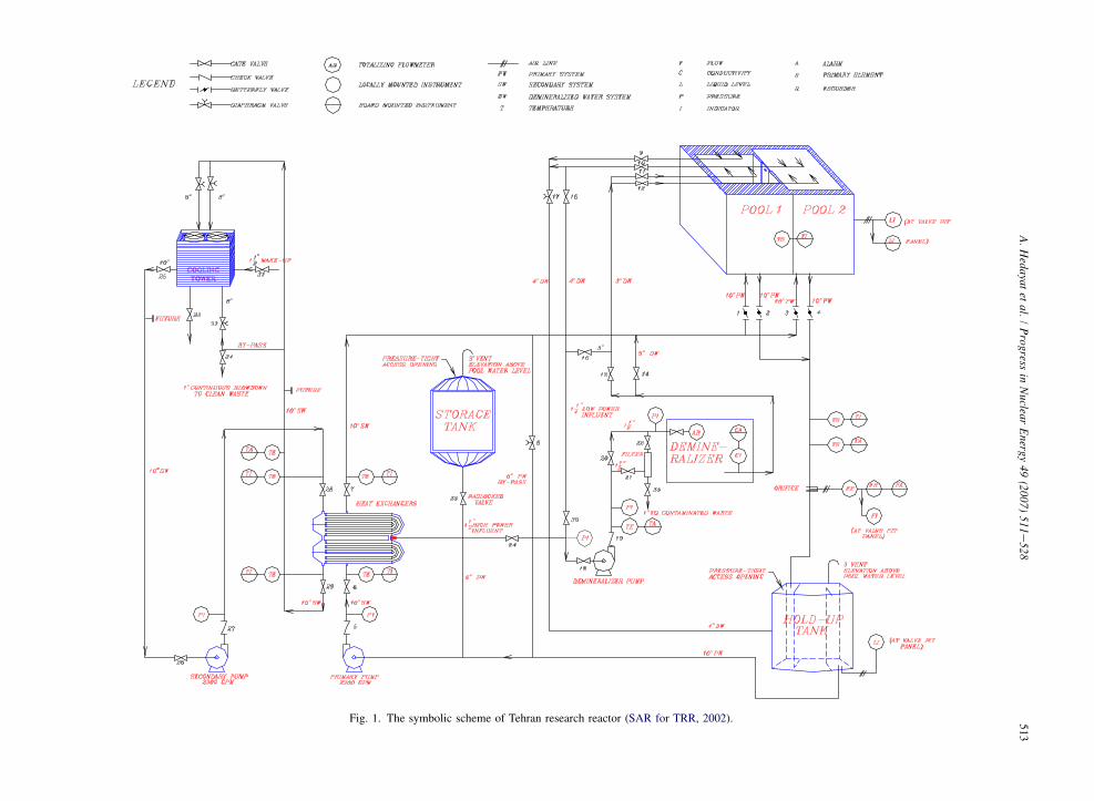
Tehran research reactor (TRR) is a 5 MW pool type research reactor located in Tehran. This reactor consists ofMTR low enriched uranium (LEU) fuel type. The reactor core is cooled by downward forced flow of light water cir-culated by a primary cooling circuit pump during the normal operational stage. But during shutdown stage, the reactorcore is cooled by upward natural convection flow through a safety flapper valve. A general symbolic plan of TRR ispresented in Fig. 1.
It’s main components are reactor core, control and safety systems, pool, holdup tank, pumps, heat exchanger, con-necting pipes, check valves, gate valves and butterfly valves. Some of the main reactor data are outlined in Tables 1and 2 and detailed specifications data are given in SAR for TRR (2002).
3. Steady state simulation
The nodalization used for simulation of TRR with RELAP5 is presented in Fig. 2. It represents both specificationsand modeling of TRR main components, and also includes all of the basic concepts for simulation. After the nodal-ization is constructed, actual simulation can be achieved because nodalization specifications are adapted by actualgathered data.
The important parts are as follows.
Nomenclature
A cross-sectional area, constant numberB constant numberCf constant numberD junction diameterF total hot channel factorhL head lossK loss factorL equivalent lengthP reactor powerq00 heat flux per unit surfaceRe Reynolds numberx, z coordinate directions, hydrodynamic variable vectorsr density
Subscriptsav average valueL lossmax maximum valueturb turbulent flow1, 2 vector indexes
51
3A
.H
edayatet
al./
Progress
inN
uclearE
nergy49
(2007)511
e528
Fig. 1. The symbolic scheme of Tehran research reactor (SAR for TRR, 2002).

514 A. Hedayat et al. / Progress in Nuclear Energy 49 (2007) 511e528
3.1. Plant nodalization
The main nodalization components are presented in Table 2.It should be noted that the scalar properties of flow such as pressure and temperature are defined at control volume
centers (Table 3). These centers are called meshes. But the vector quantities such as velocities are defined on the con-trol volume boundaries (RELAP5/MOD3 code manual, 1999).
Now a brief description of the most important parts of this nodalization is presented. The reactor pool of TRR con-sists of two parts which can be separated by an aluminum plate. In this nodalization, the pool is divided into six partswhich are modeled by P130, B200, P285 (1, 2, 3), P290 and three major channels for the core. The hot, average andbypass channels sequentially are modeled by P201, P202 and P203, respectively. These channels are connected toB200 at the top and to B205 at the bottom of themselves. B205 is the plenum located at the bottom of the core.This volume is connected to the pool exit coolant pipe (P210) during normal operational state and connected tothe water surrounding the core at pool section (II), P290, by safety flapper valve (V206) during shutdown phase.P290 is also connected to volume 1 of P285 and B200. Hence, the operation of pointed systems based on crossand direct flow through these volumes can be similar to circulation at pool and core for both forced and natural cir-culation flows. TDV110 simulates the air enclosed in reactor containment at the top of the pool. The collection ofTDV100, V105 and their trip system models the operation of the makeup system. The primary circuit pipeline
Table 1
Specifications and main operating conditions of Tehran research reactor
Core material
Coolant Light water
Fuel element Plate-type clad in Al
Moderator Light water
Nuclear fuel MTR (LEU)
Reflector Graphite/light water
Thermo-hydraulics
Cladding thermal conductivity (W/m K) 167.0
Cooling method Forced flow
Fuel thermal conductivity (W/m K) 10.0
Holdup tank water volume (m3) 37.417
Inlet coolant temperature (�C) 37.8
Pool water volume (m3) 477.8
Primary cooling loop mass flow rate (gpm) 2200
Pump head (m) 30.48
Secondary cooling loop mass flow rate (gpm) 2300
Total heat transfer surfaces (cm2) for standard fuel elements (SFE) 14,022.0
Total heat transfer surfaces (cm2) for control fuel elements (CFE) 10,332.0
Total power peaking factor (for codes) 3.0
Fuel element dimensions
Fuel height (cm) 70.5
Fuel length (cm) 8.1
Fuel width (cm) 7.07
Number of plates in standard fuel elements 19
Passing cooling water cross-section (cm2) at (CFE) 25.81
Passing cooling water cross-section (cm2) at (SFE) 33.92
Plate clad thickness (mm) 0.4
Plate clad height (cm) 61.5
Plate clad width (cm) 6.0
Plate meat (mm) 0.7
Water channel between plates (mm) 2.7
Fuel meat235U (%) 12.44238U (%) 49.78
O (%) 11.17
Al (%) 26.50
515A. Hedayat et al. / Progress in Nuclear Energy 49 (2007) 511e528
between the pool and butterfly valve is modeled by P210 and V212. Remaining path up to holdup tank is considered asP215 and P218 where a pit valve (V217) is located between them. The water logged volume of holdup tank duringnormal operational state is presented by five volumes in P220 and also TDV226 which is a time dependent volumethat should be considered for upper empty part. The next important component after holdup tank is the primary circuitmain pump (Pump 240) connected to the holdup tank by P236. P240, V242, P244, J245, P246, V242, and P249 that area collection of pipes, elbows, junctions, check and gate valves which connect the pump outlet flow to inlet shell part ofheat exchanger. Final constituent of TRR is heat exchanger. To simulate this part (Atomic Energy Organization,1990a,b), each section is chosen as a separate component connected to the others by thermodynamic conjunctionsand branches such as MJ250 at shell type parts and B415, B425, B435, B445 at tube type parts of the heat exchanger,also the heat transfer phenomena are modeled between heat structure components associated with each other byboundary conditions. Boundaries where heat can be transferred from them are specified by dashed lines at oneside of them. The shell parts of heat exchanger are connected to the primary cooling system modeled by P251,P255 and P260. The other parts or tube type parts of that are connected to the secondary cooling system. Inlet andoutlet flows of tube parts of heat exchanger at secondary cooling system are simulated by two time dependent volumesTDV400 and TDV460. Tubes at horizontal heat exchanger are classified into four separate parts. These tubes are mod-eled by P410, P420, P440, and P450 which are connected to each other by branches inside each shell and are con-nected to each other by P430 between the two primary shells. The remaining pipelines and valves from heatexchanger outlet to pool section (I) inlet are P262, a gate valve (V263), P265, a butterfly (V270), and finally P285.Usually, each pipe contains a number of volumes that have some special geometrical characteristics such as internaljunction flow area, horizontal angle, vertical angle and elevation change from the reference point. Hence, each pipesuch as P210 can have some elbows, straight pipes or abrupt area changes.
For LOCA analyses, two separate sections composed of valve and time dependent volumes should be considered.V300 and TDV315 can be considered for large break analyses above the gird plate and also V330 and TDV335 areconnected to P210 for large break analyses below the gird plate.
Now, after the nodalization and its specifications are provided the simulation can be done.
3.2. Form loss calculations
The wall friction is determined based on volume flow regime map using DarcyeWeisbach friction factors. The wallfriction force terms include only wall shear effects.
Two different types of abrupt area changes are expansion and contraction. For flow expansion, the head loss factoris obtained by BordaeCarnot formulation (Venard, 1965).
hL ¼1
2
�1�A2
A1
�2
V22 ð1Þ
Table 2
Main nodalization components and their relative reference code
Component Reference code
Average channel P201
Hot channel P202
Bypass channel P203
Main coolant pump Pump 240
Natural convection valve V206
Heat exchanger P251eP260, (P, B)405e455
Holdup tank P220, TDV226
Reactor pool P130, B200, P285, P290
Pool atmosphere simulator TDV110
Makeup system TDV100, V105
Break one V300, TDV315
Break two V330, TDV33

516 A. Hedayat et al. / Progress in Nuclear Energy 49 (2007) 511e528
Fig. 2. RELAP nodalization for Tehran research reactor.

517A. Hedayat et al. / Progress in Nuclear Energy 49 (2007) 511e528
Hence, the friction factor is:
K ¼�
1�A2
A1
�2
ð2Þ
And so the pressure drop is:
DPL ¼ rhL ð3Þ
In case of the contraction of flow, these factors similarly can be gained by mentioned correlations if only A2 is re-placed by Ac or minimum cross-section of passing flow.
Other form losses created by valves, junctions and branches which are dependent on experimental values are ob-tained from mechanical references (Valves, Piping & Pipelines in Handbook, 1996). In RELAP5 code, user specifiedform losses can be given in the following form:
kf ¼ Af þBfRe�Cf ð4Þ
In this simulation, because at the normal operational state of TRR the Reynolds number is higher than 10,000 andpipes are smooth, the DarcyeWeisbach friction factor based on Reynolds number from Moody chart is calculated bythe following correlation:
fturb ¼ 0:0032þ 0:221
Re0:237ð5Þ
Afterwards, the form loss factors can be calculated by this correlation.
k ¼ f
�L
D
�ð6Þ
f, L and D are Darcy factor, equivalent length (Valves, Piping & Pipelines in Handbook, 1996) and thermo-hydraulicdiameter, respectively.
3.3. Heat structure models
Heat structures are assumed to be represented by one-dimensional heat conduction in rectangular or cylindricalgeometry. Surface multipliers (RELAP5/MOD3 code manual, 1999) are used to convert the unit surface of one-dimensional calculation to the actual surface of heat structure. A finite difference method is used to achieve theheat conduction solutions. Each mesh interval contains a different mesh spacing, a different material or both.
For simulating the thermal power in the reactor, two different types of channels, average and hot channels, are con-sidered. The average channel is responsible for general and almost all of the thermal operations of the reactor. A cosinefunction is considered for both radial and axial heat generations of fuel plates. Hence, the power at average channelcan be approximated by correlation (7):
Pðx;zÞaverage-channel ¼ 7:5482cos�px
a
�cos�pz
L
�ð7Þ
Table 3
Core channels’ partitions
Volume number Elevation change
(from top of the core) (cm)
Mesh number Elevation change
(from top of the core) (cm)
1 10 1 5
2 20 2 15
3 30 3 25
4 40 4 35
5 50 5 45
6 60 6 55
7 70 7 65

518 A. Hedayat et al. / Progress in Nuclear Energy 49 (2007) 511e528
In this method, the extrapolated length is omitted. Hence, a is the fuel plate’s width and L is the fuel plate’s height.The hot channel is also calculated because of it’s importance for the safety analyses. The maximum heat flux at hot
channel is calculated by correlation (8) (El-Wakil, 1971):
q00max ¼ q00avF ð8Þ
In this correlation, qmax00 , qav
00 and F are maximum heat flux in hot channel, average heat flux in average channel andoverall hot spot factor, respectively. Now because of proportionality between heat flux and thermal power, similar cor-relation is obtained.
ðPmaxÞhot-channel ¼ ðPavÞaverage-channelF ð9Þ
The overall hot spot factor or total hot channel factor for safety analyses done by thermalehydraulic codes shouldbe considered 3 (SAR for TRR, 2002). This value is higher than the real value. Similar to previous discussion, a cosinedistribution for both radial and axial heat flux in fuel plates is considered. Hence, the power at hot channel can beapproximated by correlation (10):
Pðx;yÞhot-channel ¼ 0:584cos�px
a
�cos�pz
L
�ð10Þ
For heat exchanger simulation, each separate part of it is taken as a specific heat structure with it’s boundaryconditions.
4. Steady state results and comparison
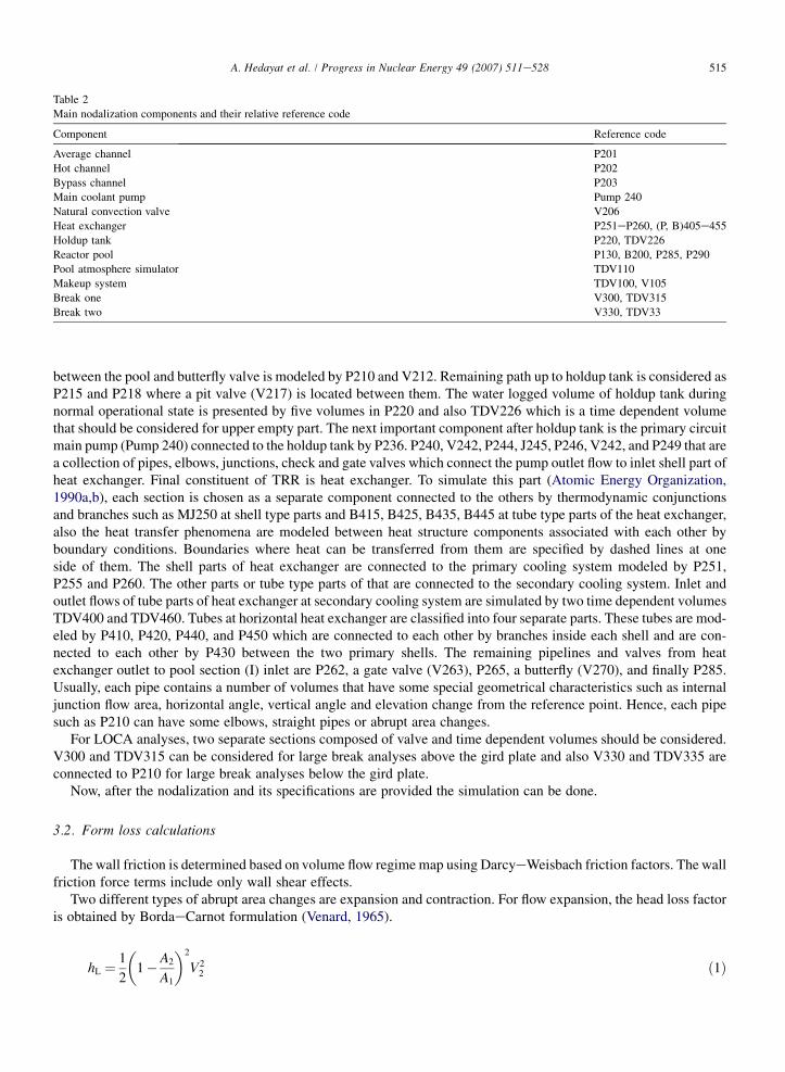
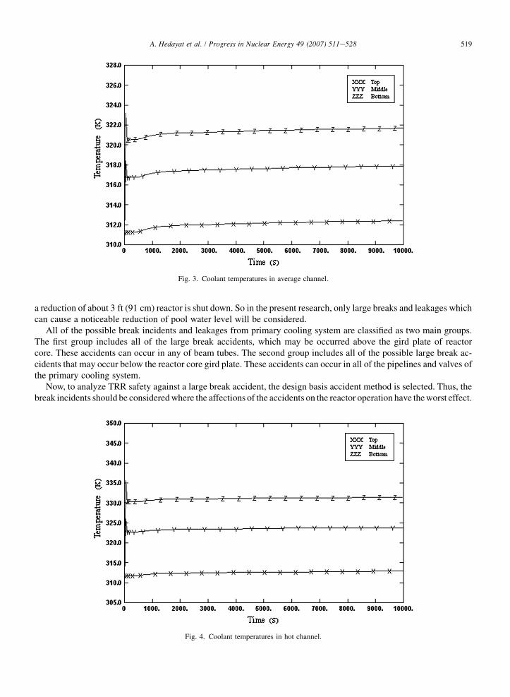
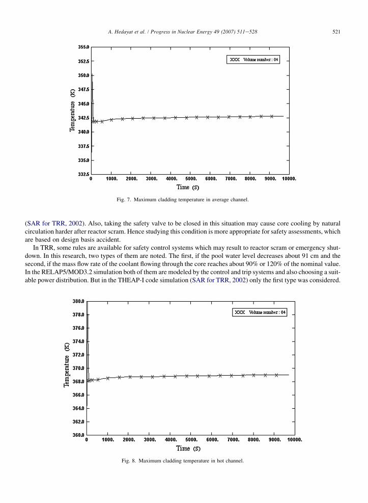
Important results of the steady state simulation and also a comparison between the results of RELAP5/MOD3.2code and the average experimental values registered in safety analyses report of Tehran research reactor (SAR forTRR, 2002) are presented in Figs. 3e8 and Table 4.
5. Discussion of steady state results
Table 4 shows a comparison between the results of simulation by RELAP5/MOD3.2 code and the experimentaldata (SAR for TRR, 2002). It can be seen that presented data are very similar. But little differences between someof them can be seen.
The reactor specifications reported at SAR (SAR for TRR, 2002) are the average experimental values. Hence, twoimportant points should be considered. The most important point is that research reactors work at low pressure and lowtemperature and also some of the main reactor components transfer heat to their environment. For example, water thatis flowing through pool or holdup tank bounded by the enclosed air, or the shell type sides of heat exchanger transfersome heat to the air in pump room. They have different temperatures at various seasons. The second problem is thatsome details of reactor thermo-hydraulic quantities or heat structure data are not available from SAR (SAR for TRR,2002), therefore standard values from reference books (Valves, Piping & Pipelines in Handbook, 1996) are used. Alsosome of the data extracted from SAR are safety margin values, such as total hot channel factor which is above the realvalue.
Because of all mentioned reasons and by comparison between the simulation results and SAR (SAR for TRR,2002), the ability of RELAP5/MOD3.2 code has been demonstrated for research reactor applications.
6. Methodology for TRR LOCA analyses
Various incidents such as ruptures and leakages from pipes and valves which are located in primarily cooling sys-tem, ruptures of beam tubes, and breaks at the pool wall which are caused by severe accidents like strong earthquakescan lead to the loss of coolant accident in TRR.
If the mass flow rate of the exiting coolant from rupture location is less than the mass flow rate of the makeup sys-tem which is 25 gpm or 95 l/min, pool water level will not change. But if exiting mass flow rate is more than 25 gpm,the pool water level will be decreased. After decreasing about 1 ft (30.48 cm), the alarm system is activated and after
519A. Hedayat et al. / Progress in Nuclear Energy 49 (2007) 511e528
a reduction of about 3 ft (91 cm) reactor is shut down. So in the present research, only large breaks and leakages whichcan cause a noticeable reduction of pool water level will be considered.
All of the possible break incidents and leakages from primary cooling system are classified as two main groups.The first group includes all of the large break accidents, which may be occurred above the gird plate of reactorcore. These accidents can occur in any of beam tubes. The second group includes all of the possible large break ac-cidents that may occur below the reactor core gird plate. These accidents can occur in all of the pipelines and valves ofthe primary cooling system.
Now, to analyze TRR safety against a large break accident, the design basis accident method is selected. Thus, thebreak incidents should be considered where the affections of the accidents on the reactor operation have the worst effect.
Fig. 3. Coolant temperatures in average channel.
Fig. 4. Coolant temperatures in hot channel.

520 A. Hedayat et al. / Progress in Nuclear Energy 49 (2007) 511e528
To analyze LOCAs which are caused by breaks above the gird plate, the complete break of the 12 inches squarebeam tube located near the pool wall should be selected because it has the greatest cross-sectional area and also has theminimum relative height with respect to the core.
To analyze LOCAs which are caused by breaks below the gird plate, the complete break of the 10 inches outlet coolingpipe where crossing the pool floor should be chosen because coolant flowing through any selected location in the primarycooling system has a higher friction loss with respect to the initial selection. So coolant exits with less velocity than theinitial choice. Hence, the most dangerous state that should be studied to secure safety margins is the first selection.
The same RELAP5 nodalization as used for steady state condition is used to analyze the LOCA accident, exceptthat the safety flapper valve is taken closed to compare the results of the simulation with the THEAP-I code results
Fig. 5. Coolant velocities in average channel.
Fig. 6. Coolant velocities in hot channel.
521A. Hedayat et al. / Progress in Nuclear Energy 49 (2007) 511e528
(SAR for TRR, 2002). Also, taking the safety valve to be closed in this situation may cause core cooling by naturalcirculation harder after reactor scram. Hence studying this condition is more appropriate for safety assessments, whichare based on design basis accident.
In TRR, some rules are available for safety control systems which may result to reactor scram or emergency shut-down. In this research, two types of them are noted. The first, if the pool water level decreases about 91 cm and thesecond, if the mass flow rate of the coolant flowing through the core reaches about 90% or 120% of the nominal value.In the RELAP5/MOD3.2 simulation both of them are modeled by the control and trip systems and also choosing a suit-able power distribution. But in the THEAP-I code simulation (SAR for TRR, 2002) only the first type was considered.
Fig. 7. Maximum cladding temperature in average channel.
Fig. 8. Maximum cladding temperature in hot channel.
522 A. Hedayat et al. / Progress in Nuclear Energy 49 (2007) 511e528
7. LOCA simulation results and discussion
To model a loss of coolant accident, a time dependent volume is attached to the respective point of RELAP5 nod-alization by a valve. In this LOCA simulation, after 100 s of steady state operation of TRR, LOCA begins by openingof this valve. Then cooling flow expands to a time dependent volume. This flow expansion to the volume which con-tains air simulates the actual break conditions. So an implicit dynamic environment is gained to simulate LOCA. Abrief review of gained results is presented.
7.1. LOCA simulation caused by a large break incident in the 12 inches beam tube
To model a LOCA caused by a large break incident in the 12 inches beam tube which is located at the height of1.66 m above the pool floor, near the core top, V300 and TDV315 could be selected. After 100 s steady state operationof the reactor at 5 MW power, V300 is opened. Because of great and prompt expansion which occurred just near thetop of the reactor core, the reactor suddenly is shut down. Thus the thermal power of fuel assemblies is reduced to thefission fragments heat decay. Also a major pump head loss is caused by large LOCA expansion. Thus this incidentprolongs pool water supplying by the coolant stored in the pipelines and the holdup tank. After the pool water levelhas a decrease of about 30 cm, the makeup system which is not so effective in this situation is activated. The poolwater level decreased to the top of reactor core after about 28 min. The reactor core is completely empty after about31.6 min. During this time, air is refilling the coolant channels. This phenomenon caused a great decrease in the heattransfer factors. So fuel clad temperatures increase. These temperatures reach to the maximum values of 183.5 �C inthe average channel and 343 �C in the hot channel. The other maximum temperatures at different heights of theaverage and hot channel claddings can be seen in Table 5.
Then, effective natural air convection through the hot, average, and bypass channels circulates. This circulating ofair causes an effective reduction of clad temperatures. So in this event, clad temperatures are remained below thecladding (Al-T6061) melting point temperature which is about 587 �C.
Table 4
A comparison between the results of simulation and the experimental data (SAR for TRR, 2002)
Thermo-hydraulic variables Results of the
RELAP5 code
Data registered
at SAR (2002)
Hot channel outlet coolant temperature (�C) 58 e
Heat exchanger inlet primary coolant temperature (�C) 45.5 46.5
Heat exchanger outlet primary coolant temperature (�C) 38.9 37.8
Heat exchanger inlet secondary coolant temperature (�C) 30.6 30.6
Heat exchanger outlet secondary coolant temperature (�C) 38.7 38.9
Average velocity of coolant flowing through the core (m/s) 1.36 1.36
Average heat flux (W/cm2) 13.84 13.4
Maximum heat flux (W/cm2) 42 40.1
Maximum pool water temperature (�C) 38.9 37.8
Average channel outlet coolant temperature (�C) 48.76 e
Table 5
Maximum cladding temperatures at various channel heights
Channel elevation
change (from the top) (cm)
Maximum clad temperatures
at the average channel (�C)
Maximum clad temperatures
at the hot channel (�C)
5 131.469 244.939
15 167.66 314.299
25 183.537 343.505
35 175.934 323.777
45 142.483 270.565
55 102.352 172.645
65 57.854 77.605

523A. Hedayat et al. / Progress in Nuclear Energy 49 (2007) 511e528
Some results of this transient simulation which are more important due to safety margin assessments are presentedas graphs in Figs. 9e12. They are scaled by SI units.
7.2. LOCA simulation caused by a large break incident in the 10 inches outlet coolant pipe
To model a LOCA caused by a large break incident in the 10 inches outlet coolant pipe which is crossing the poolfloor, V330 and TDV335 could be considered. After 100 s steady state operation of the reactor at the 5 MW power,V330 is opened. Because of great and prompt expansion which is occurred just after the core cooling outlet, mass flowrate of the core increases. Thus the reactor is shut down a few seconds after the accident and then the thermal power of
Fig. 9. Hot channel liquid phase temperatures.
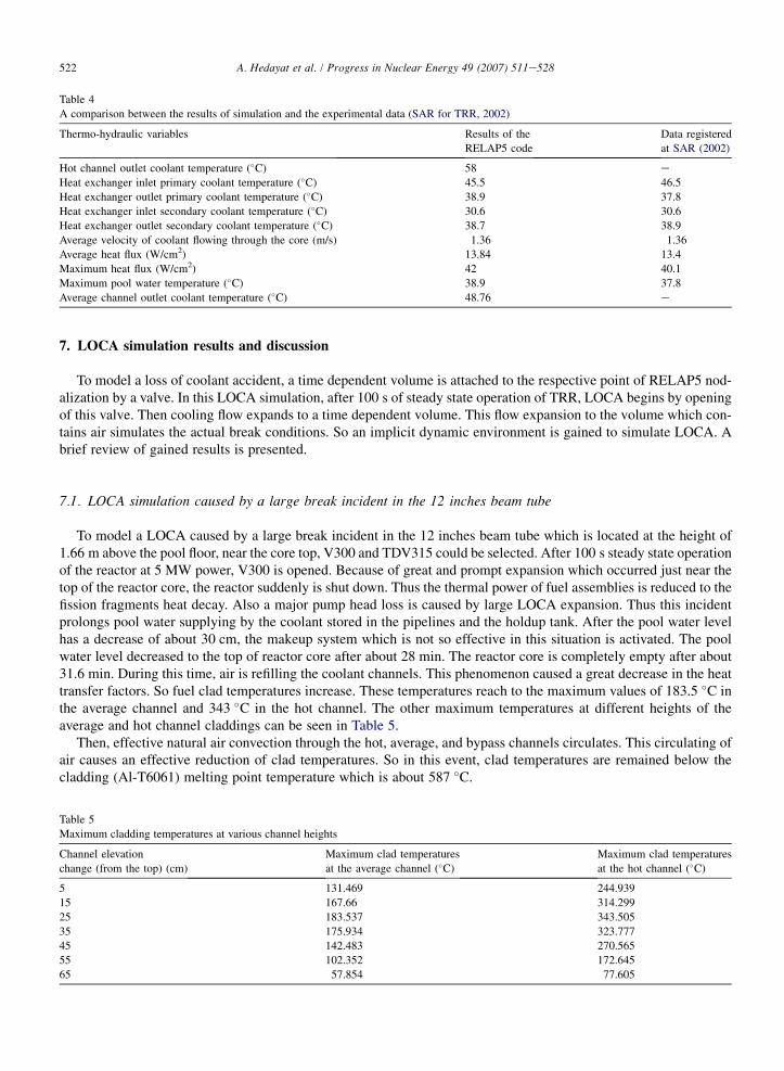
Fig. 10. Average channel liquid phase temperatures.

524 A. Hedayat et al. / Progress in Nuclear Energy 49 (2007) 511e528
fuel assemblies is reduced to the fission fragments heat decay. Also a major pump head loss is caused by large LOCAexpansion. Thus this incident prolongs pool water supplying by the coolant which is stored in the pipelines and theholdup tank. After the pool water level has a decrease of about 30 cm, the makeup system which is not so effective inthis situation is activated. The pool water decreases to the top of reactor core after about 42.6 min. Before this time,because of exiting coolant from bottom of the core by gravity force and expansion phenomena, the coolant can havea sufficient mass flow rate for preventing from other secondary local accidents such as LOFA. The reactor core is com-pletely empty after about 48 min. During this time, air is refilling the coolant channels. This phenomenon causeda great decrease in the heat transfer factors. So fuel clad temperatures increase. These temperatures reach to the
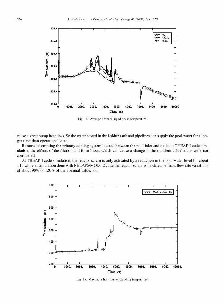
Fig. 11. Maximum hot channel cladding temperature.
Fig. 12. Maximum average channel cladding temperature.

525A. Hedayat et al. / Progress in Nuclear Energy 49 (2007) 511e528
maximum values of 190.6 �C in the average channel and 387 �C in the hot channel. The other maximum temperaturesat different heights of the average and hot channel claddings are given in Table 6.
Finally, effective natural air convection through the hot, average, and bypass channels circulates. This circulating ofair causes an effective reduction of clad temperatures. So in this event, clad temperatures are remained below the clad-ding (Al-T6061) melting point temperature which is about 587 �C.
Some results of this transient simulation which are more important due to safety margin assessments are presentedas graphs in Figs. 13e16. They are scaled by SI units.
7.3. A comparison between the results of RELAP5/MOD3.2 code and THEAP-I code simulations
This comparison is briefly presented in Tables 7 and 8. Then the most important reasons for differences between theresults of LOCA analyses done with RELAP5/MOD3.2 and THEAP-I codes are mentioned.
The most important differences between the results of the loss of coolant accident analyses gained by RELAP5/MOD3.2 and THEAP-I codes can be consequences of the differences between the modeling methods used. Someof them are presented here.
At simulation done with THEAP-I code, accident influences on the other components of the primarily cooling cir-cuit were omitted. Especially, pressure losses due to large break incident that may have notable effects on thethermo-hydraulic phenomena was not considered. These effects can be considerable, for example the accident can
Table 6
Maximum cladding temperatures at various channel heights
Channel elevation
change (from the top) (cm)
Maximum clad temperatures
at the average channel (�C)
Maximum clad temperatures
at the hot channel (�C)
5 54.034 74.469
15 101.04 203.604
25 151.735 302.118
35 181.344 366.257
45 190.614 387.747
55 178.02 363.184
65 149.47 310.276
Fig. 13. Hot channel liquid phase temperature.
526 A. Hedayat et al. / Progress in Nuclear Energy 49 (2007) 511e528
cause a great pump head loss. So the water stored in the holdup tank and pipelines can supply the pool water for a lon-ger time than operational state.
Because of omitting the primary cooling system located between the pool inlet and outlet at THEAP-I code sim-ulation, the effects of the friction and form losses which can cause a change in the transient calculations were notconsidered.
At THEAP-I code simulation, the reactor scram is only activated by a reduction in the pool water level for about1 ft, while at simulation done with RELAP5/MOD3.2 code the reactor scram is modeled by mass flow rate variationsof about 90% or 120% of the nominal value, too.
Fig. 14. Average channel liquid phase temperature.
Fig. 15. Maximum hot channel cladding temperature.

527A. Hedayat et al. / Progress in Nuclear Energy 49 (2007) 511e528
8. Conclusions
With respect to the steady state results and also by comparison between the transient results and SAR (SAR forTRR, 2002) which were briefly presented, the abilities of both RELAP5/MOD3.2 and presented nodalization areproved to be used for research reactor applications.
After introducing an appropriate methodology for loss of coolant accident analyses on TRR, two major types ofLB-LOCAs were simulated. It can be seen that during loss of water coolant in the core, a natural convection of airis circulating through the fuel assemblies which causes a suitable cooling which can prevent core melting aftercore is completely empty. On the other hand, in the LOCA simulation which was caused by a large break in the12 inches beam tube, after the hottest point reached a temperature of about 343 �C, it’s temperature decreased toa safe value. Also in the LOCA simulation caused by a large break in the 10 inches outlet coolant pipe, after hot chan-nel clad temperature at the hottest axial section reached about 387 �C, it was cooled to a safe temperature. In bothcases, the hottest temperatures at hot channel, by considering the hot channel factor to be 3 which is above thereal value, were remained under the cladding (AL, T6061) melting point which is about 587 �C.
Table 8 shows that the shortest time, for core to get completely empty in an LB-LOCA, is about 28 min. On theother hand, the core can be transported by a maximum safe velocity of 41.1 cm/min. The core should be transportedin a distance of about 5.6 m to the other pool section. Then it must be installed and isolated from the first section by the
Fig. 16. Maximum average channel cladding temperature.
Table 7
Similar inputs of the codes
Variables A LOCA analysis on the 12 inches beam tube A LOCA analysis on the 10 inches outlet coolant pipe
RELAP5/MOD3.2 THEAP-I code RELAP5/MOD3.2 THEAP-I code
Break height
related to the pool
floor (m)
1.66 1.66 0.0 0.0
Break cross-section
area (m2)
0.093 0.093 0.0507 0.0507
Break diameter (m) 0.305 0.305 0.254 0.254

528 A. Hedayat et al. / Progress in Nuclear Energy 49 (2007) 511e528
separating plate. All of this can be done in about 15 min (SAR for TRR, 2002). By considering a safety margin of 20%,this time increases to about 18 min. Hence, in a large break accident, the core can be set up at the other pool sectionand isolated from the first section before the pool water level decreased to the top of the core.
Finally, because of all the achieved results, it can be concluded that Tehran research reactor (TRR) is safe againstthe loss of coolant accident (LOCA).
And although RELAP5/MOD3.2 code can simulate research reactors actually at operating conditions, it seems thatthis code simulates large transient phases less accurately specially in low pressure two phase mixtures (water and air).
References
Atomic Energy Organization, 1990a. Construction Drawing, Demineralized Water Cooler. Suisio, Bergamo, Italy. IRN/342, 8504 (NUM. DIS.
DWG. NUM.9182).
Atomic Energy Organization, 1990b. Heat Exchangers. Document Front Sheet. Suisio, Bergamo, Italy. CALC/8504, IRN/342.
Davis, C.B., 2002. Applicability of RELAP5/MOD3.2 to research reactors. In: IAEA Regional Training Workshop on Safety Analysis Method-
ology and Computer Code Utilization. KINS, Daejeon, South Korea.
Di Maro, B., Pierro, F., Bousbia Salah, A., D’Auria, F., May 2003. Analysis of a pump trip in a typical research reactor by RELAP5/MOD 3.3. In:
Proceedings of ICAPP’03, Cordoba, Spain (paper 3215).
El-Wakil, M.M., 1971. Nuclear Heat Transport. International Textbook Company, Scranton.
Hamidouche, T., Bousbia-Salah, A., Adorni, M., D’Auria, F., 2004. Dynamic calculations of the IAEA safety MTR research reactor benchmark
problem using RELAP5/3.2 code. Annals of Nuclear Energy 31, 1385e1402.
Lin, M., Su, Y., HU, R., Zhang, R., Yang, Y., March 2005. Development of a thermalehydraulic system code for simulators based on RELAP5
code. Nuclear Engineering and Design 235 (6), 925e936.
Micaelli, J.C., Barre, F., Bestion, D., 1995. CATHARE code development and assessment methodologies. In: Transactions of the ANS, Winter
Meeting San Francisco, October 29eNovember 2, vol. 73, pp. 509e510.
RELAP5/MOD3 code manual, June 1999. Code Structure, System Models, and Solution Methods, vols. IeV. Idaho National Engineering
Laboratory (NUREG/CR-5535).
SAR for TRR, October 2002. Safety analysis report for Tehran research reactor. Nuclear Research Center of the Atomic Energy Organization of
Iran, Tehran.
Valves, Piping & Pipelines in Handbook, second ed., 1996. Elsevier Advanced Technology, Kidlington, Oxford.
Venard, J.K., 1965. One-dimensional Flow. In: Streeter, V.L. (Ed.), Handbook of Fluid Dynamics, first ed. McGraw Hill, New York.
Wolfert, K., Teschendorff, V., Lerchl, G., Miro, J., Burwell, M.J., 1989. The thermalehydraulic code ATHLET for analysis of PWR and BWR
systems. In: Proceedings of NURETH-4, Karlsruhe, vol. II, pp. 1234e1239.
Table 8
A comparison between results of the RELAP5/MOD3.2 and THEAP-I code simulations of TRR
Variables Results of the LOCA analyses on the 12 inches
beam tube
Results of the LOCA analyses on the 10 inches
outlet coolant pipe
RELAP5/MOD3.2 THEAP-I code RELAP5/MOD3.2 THEAP-I code
Scram time 0.17 s 2.4 min 1.15 s 1.83 min
Time needed for pool
water depletion up to
the core top (min)
28 31.6 42.6 46.2
Core complete
depletion time (min)
31.6 e 48 51