modell tba redundant analog - twk-elektronik gmbh · protection type (din en 60529): ip 67 (for...
TRANSCRIPT
Absolute single-turn rotary encoderTBA redundant analogueModel: TBA58-KA360WR2SB01
Document No.: TBA 15241 AEDate: 14.10.2019
TWK-ELEKTRONIK GmbH 40210 Düsseldorf [email protected]ße 108 Tel.: +49 211 961170 visit us at | twk.de
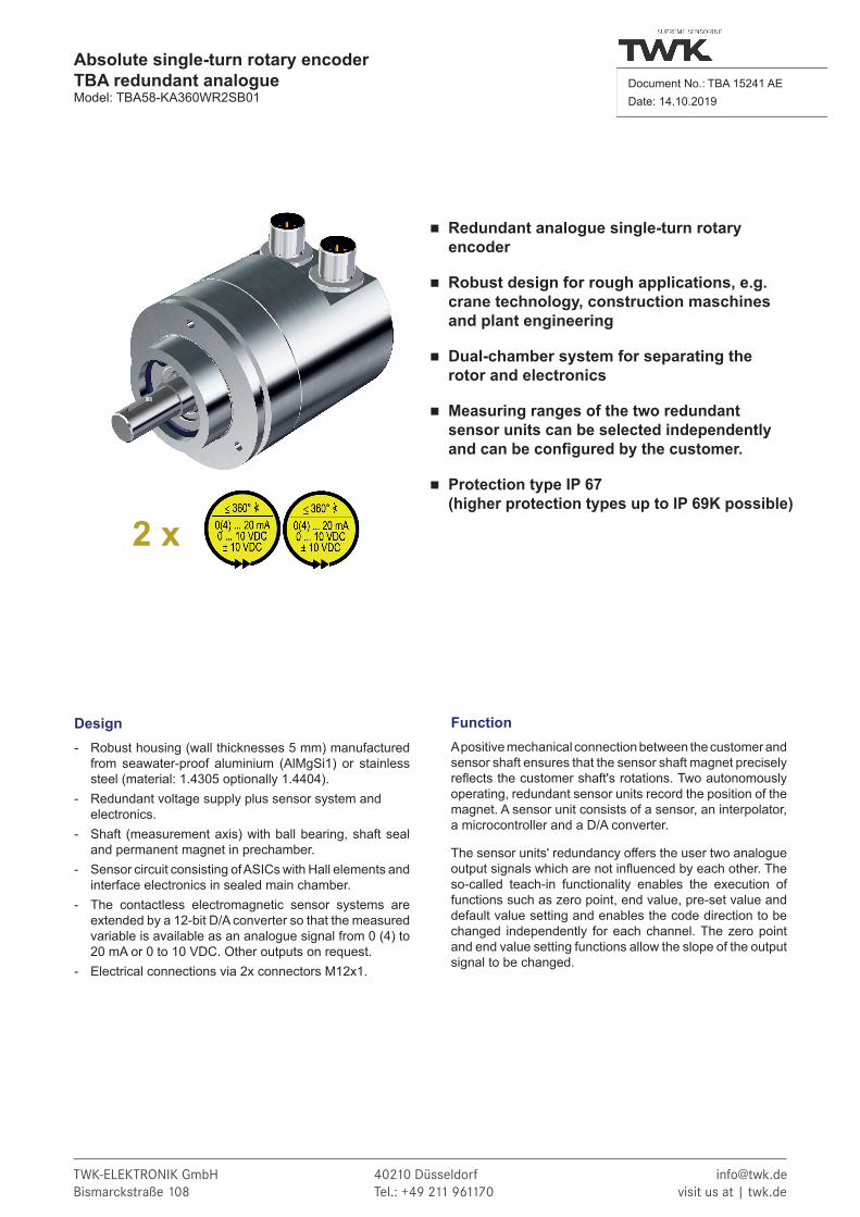
Redundant analogue single-turn rotary encoder
Robust design for rough applications, e.g. crane technology, construction maschines and plant engineering
Dual-chamber system for separating the rotor and electronics
Measuring ranges of the two redundant sensor units can be selected independently andcanbeconfiguredbythecustomer.
Protection type IP 67 (higher protection types up to IP 69K possible)
Design- Robust housing (wall thicknesses 5 mm) manufactured
from seawater-proof aluminium (AlMgSi1) or stainless steel (material: 1.4305 optionally 1.4404).
- Redundant voltage supply plus sensor system and electronics.
- Shaft (measurement axis) with ball bearing, shaft seal and permanent magnet in prechamber.
- Sensor circuit consisting of ASICs with Hall elements and interface electronics in sealed main chamber.
- The contactless electromagnetic sensor systems are extended by a 12-bit D/A converter so that the measured variable is available as an analogue signal from 0 (4) to 20 mA or 0 to 10 VDC. Other outputs on request.
- Electrical connections via 2x connectors M12x1.
2 x
FunctionA positive mechanical connection between the customer and sensor shaft ensures that the sensor shaft magnet precisely reflects the customer shaft's rotations. Two autonomously operating, redundant sensor units record the position of the magnet. A sensor unit consists of a sensor, an interpolator, a microcontroller and a D/A converter.
The sensor units' redundancy offers the user two analogue output signals which are not influenced by each other. The so-called teach-in functionality enables the execution of functions such as zero point, end value, pre-set value and default value setting and enables the code direction to be changed independently for each channel. The zero point and end value setting functions allow the slope of the output signal to be changed.

Date: 14.10.2019 Page 2 of 10 Document No. TBA 15241 AE
Absolute single-turn rotary encoderTBA redundant analogueModel: TBA58-KA360WR2SBxx
Technical data
Electrical data Sensor system: ASICs with Hall elements Operating voltage: 9 to 36 VDC, protected against polarity reversal (output: A, B, C****) (5 VDC on request) Power consumption: < 1.8 W per channel Measuring range: Up to 360° D/A converter: 12-bit Code path: CW* or CCW** can be set Accuracy: ± 0.15 % (with reference to 360°) Reproducibility: ± 0.02 % (with reference to 360°) Temperature drift: < 0.01 % / °K typ. (with reference to 360°) System synchronisation: Static ≤ 0.5 % (with reference to 360°) Dynamic ≤ 5 % (with reference to 360°) at 3000 rpm
Electrical output data
Current output A, B: A: 0 to 20 mA; B: 4 to 20 mA Burden: 0 ... 500 Ω Voltage output C C: 0 to 10 VDC; Output current: Max. 5 mA corresp. to load resistance ≥ 2 kΩ resistant to short-circuit
Mechanical data Operating speed: 12,000 rpm Angular acceleration: 105 rad/s² max. Moment of inertia (rotor): 20 gcm² Operating torque: ≤ 2 Ncm Starting torque: ≤ 3 Ncm Perm. shaft load: 250 N axially, 250 N radially Bearing service life: ≥ 109 revolutions *** Weight: Aluminium approx. 0.4 kg, stainless steel approx. 0.6 kg
*) CW = increasing signal clockwise viewed looking towards the shaft**) CCW = increasing signal counter-clockwise viewed looking towards the shaft***) This value applies at maximum shaft load****) See page 6
Environmental data Operating temperature range: - 40 °C to + 85 °C Storage temperature range: - 40 °C to + 100 °C (without packaging) Resistance To shock: 500 m/s²; 11 ms DIN EN 60068-2-27 To vibration: 500 m/s²;10 Hz ... 2000 Hz DIN EN 60068-2-6 EMC standards: DIN EN 61 000 - 6 - 2 Imission (burst/ESD/etc.) DIN EN 61 000 - 6 - 4 Emission Protection type (DIN EN 60529): IP 67 (For higher protection types up to IP 69K, please contact our technical staff)

Date: 14.10.2019 Page 3 of 10 Document No. TBA 15241 AE
Absolute single-turn rotary encoderTBA redundant analogueModel: TBA58-KA360WR2SBxx
Principle circuit diagram
SN
Magnetsingle-turn
Controller / sensor 1 Controller / sensor 2
Sensor 1 Sensor 2
D
A
D
A
Interpolator Interpolator
EMC filter EMC filter
U/I -Out -V +VB U/I-OutB -V +VB B

Date: 14.10.2019 Page 4 of 10 Document No. TBA 15241 AE
Absolute single-turn rotary encoderTBA redundant analogueModel: TBA58-KA360WR2SBxx
Measuring range setting
Standard measuring rangeBoth redundant sensor units are set to a measuring range of 360° as default (characteristic curve 1). If a smaller measuring range is specified in the order number, both sensor units are synchronously set to this specified measuring range in the fac-tory. Outside of the measuring range, the characteristic curves then have a symmetrically subdivided overflow and underflow (characteristic curve 2. Special characteristic curves, e.g. without overflow or underflow, are possible on request.
Characteristic curve 1: measuring range 360° (output B*) Characteristic curve 2: measuring range 100° as an example (output B*)
Characteristic curve 3: example of different measuring ranges (output B*)
First sensor: measuring range 270°, ascending Second sensor: measuring range 270°, descending, shifted by 45°
4 mA
20 mA
0°
Measuring range
Underflow
Overflow
270° 360°315°
4 mA
20 mA
0°
Underflow
Overflow
360°315°45°
Measuring range
Alternative measuring range
Different measuring ranges can be set for both redundant sensor units with the aid of the multifunctional pins (characteristic curve 3). These can also be set in the factory on request.
360°0°
4 mA
20 mA
4 mA
20 mA
Measuringrange
Underflow
360°0° 100° 230°
Overflow
*) See page 6
Date: 14.10.2019 Page 5 of 10 Document No. TBA 15241 AE
Absolute single-turn rotary encoderTBA redundant analogueModel: TBA58-KA360WR2SBxx
Setting option via multifunctional pins
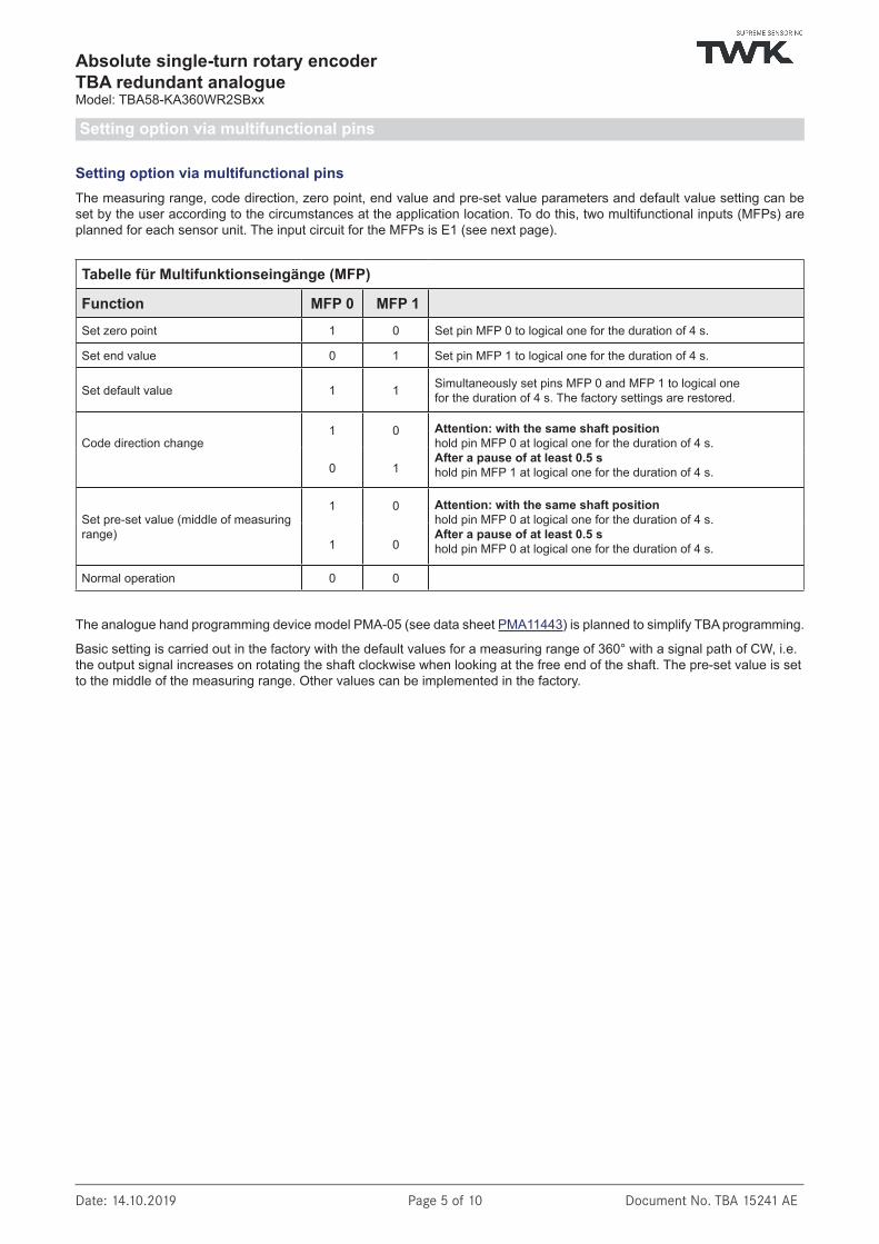
Setting option via multifunctional pinsThe measuring range, code direction, zero point, end value and pre-set value parameters and default value setting can be set by the user according to the circumstances at the application location. To do this, two multifunctional inputs (MFPs) are planned for each sensor unit. The input circuit for the MFPs is E1 (see next page).
Tabelle für Multifunktionseingänge (MFP)
Function MFP 0 MFP 1Set zero point 1 0 Set pin MFP 0 to logical one for the duration of 4 s.
Set end value 0 1 Set pin MFP 1 to logical one for the duration of 4 s.
Set default value 1 1 Simultaneously set pins MFP 0 and MFP 1 to logical onefor the duration of 4 s. The factory settings are restored.
Code direction change1 0 Attention: with the same shaft position
hold pin MFP 0 at logical one for the duration of 4 s.After a pause of at least 0.5 shold pin MFP 1 at logical one for the duration of 4 s.0 1
Set pre-set value (middle of measuring range)
1 0 Attention: with the same shaft positionhold pin MFP 0 at logical one for the duration of 4 s.After a pause of at least 0.5 shold pin MFP 0 at logical one for the duration of 4 s.1 0
Normal operation 0 0
The analogue hand programming device model PMA-05 (see data sheet PMA11443) is planned to simplify TBA programming.
Basic setting is carried out in the factory with the default values for a measuring range of 360° with a signal path of CW, i.e. the output signal increases on rotating the shaft clockwise when looking at the free end of the shaft. The pre-set value is set to the middle of the measuring range. Other values can be implemented in the factory.

Date: 14.10.2019 Page 6 of 10 Document No. TBA 15241 AE
Absolute single-turn rotary encoderTBA redundant analogueModel: TBA58-KA360WR2SBxx
Input circuit, timing diagrams and output circuits
Input circuit for multifunctional pins (MFP)
Log 1 = 11 ... VsLog 0<5Vor not connected
Input E1 aktive "high"
iV
iI
E1 specifications
Output circuits
R = 0 - 0.5 kΩIo = 0 - 20 mA
L
Output A
A0-20 mA
12 bit
D LR
Io
R = 0 - 0.5 kΩIo = 4 - 20 mA
L
Output B
A4-20 mA
12 bit
D LR
Io
R min. = 2 kΩIo max. = 5 mA
Output C
A0-10 V
12 bit
D Vo
Io
Vo = 0 ... 10 V
3. Set MFP 0 and MFP 1 simultaneously
Time difference between MFP 0 and MFP 1 ≤ 0.25 s.
Timing diagrams for the MFP settings E1
1. Set MFP 0 or MFP 1 onceSet zero point (MFP 0) Set end value (MFP 1)
2. Set MFP 0 and/or MFP 1 twice with the same shaft position
Set pre-set value (MFP 0)Code direction change (MFP 0 / MFP 1)
logical 1
logical 0logical 0
logical 1
logical 0
without position changing
t > 4 s t > 4 st > 0.5 s
logical 1
logical 0logical 0t > 4 s

Date: 14.10.2019 Page 7 of 10 Document No. TBA 15241 AE
Absolute single-turn rotary encoderTBA redundant analogueModel: TBA58-KA360WR2SBxx
Electrical connection Two round connectors M12x1, pin, 8-pin Refer to the tables below for the connection assignments; these are also enclosed with the devices.
Electrical connection, mating connector, pin diagrams, connection assignment
Pin diagram for mating connector M12x1, 8-pin (view of insertion side)
1
Socket, 4-pin,A-coded
4
2
3
2
3
1
4
Pins, 4-pin,A-coded
7
65
4
3
2 1
83
45
6
7
1 2
8
Socket, 8-pin,A-coded
Pins, 8-pin,A-coded
Mating connectors (to be ordered separately)
Order number STK8GS54 STK8WS86 STK8GS105Type M12X1 M12X1 M12X1Number of pins 8 8 8Contact design Socket, A-coded Socket, A-coded Socket, A-codedConnector design Straight Angled StraightHousing material Nickel-plated brass Nickel-plated brass Stainless steelCable ø (mm) 6 - 8 6 - 8 5.5 - 8.6Connection type Screws Screws ScrewsProtection type IP 67 IP 67 IP 67Screening On the housing On the housing On the housingMax. connection cross-section (mm²) 0.5 0.5 0.5
Contact No. Assigned with1 +VS = 9…36 V, Io typ. 80 mA
2 -VS = 0 V
3 IA = 4 … 20 mA (4096 steps = 12-bit)
4 0V analogue reference potential
5 Multifunctional input 0 (input circuit E1)
6 Multifunctional input 1 (input circuit E1)
7/8 Not connected
Connection assignment
Please note: If angled mating connectors are used, please notify us so that the device connectors can be aligned accordingly.
Date: 14.10.2019 Page 8 of 10 Document No. TBA 15241 AE
Absolute single-turn rotary encoderTBA redundant analogueModel: TBA58-KA360WR2SBxx
Order nummber
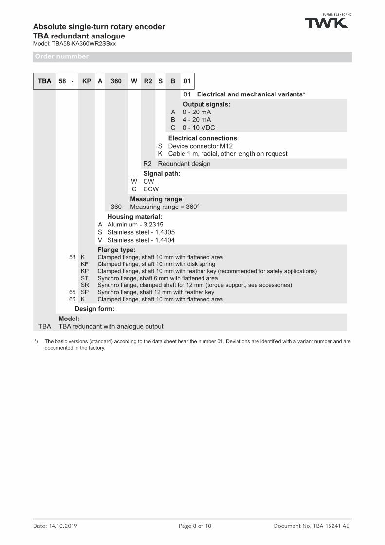
TBA 58 - KP A 360 W R2 S B 01
58
6566
01 Electrical and mechanical variants*
A B C
Output signals: 0 - 20 mA4 - 20 mA0 - 10 VDC
S K
Electrical connections: Device connector M12Cable 1 m, radial, other length on request
R2 Redundant design
W C
Signal path:CW CCW
360Measuring range: Measuring range = 360°
A SV
Housing material: Aluminium - 3.2315 Stainless steel - 1.4305Stainless steel - 1.4404
KKFKP STSRSPK
Flange type: Clamped flange, shaft 10 mm with flattened areaClamped flange, shaft 10 mm with disk springClamped flange, shaft 10 mm with feather key (recommended for safety applications)Synchro flange, shaft 6 mm with flattened areaSynchro flange, clamped shaft for 12 mm (torque support, see accessories) Synchro flange, shaft 12 mm with feather key Clamped flange, shaft 10 mm with flattened area
Design form:
TBAModel: TBA redundant with analogue output
*) The basic versions (standard) according to the data sheet bear the number 01. Deviations are identified with a variant number and are documented in the factory.

Date: 14.10.2019 Page 9 of 10 Document No. TBA 15241 AE
Absolute single-turn rotary encoderTBA redundant analogueModel: TBA58-KA360WR2SBxx
Accessories
Accessories (to be ordered separately) Mating connectors
STK 8GS54 Nickel-plated brass, straight STK 8WA86 Nickel-plated brass, angled STK 8GS105 Stainless steel, straight
Hand programming device for comfortable programming of the sensor PMA-05 See data sheet PMA11443
Fastening clamps for sensor assembly KL 66-2-S See data shee MZ10111
Play-free clamping coupling for shaft connection KK14N With groove for feather key according to DIN 6885 sheet 1 – JS9, see data sheet KK12301
Torque support/stator coupling for shaft offset compensation between the rotary encoder and drive ZMS58 Manufactured from permanently elastic plastic, see data sheet ZMS 12939

Date: 14.10.2019 Page 10 of 10 Document No. TBA 15241 AE
Absolute single-turn rotary encoderTBA redundant analogueModel: TBA58-KA360WR2SBxx
Installation drawing (Dimensions in mm)
Recommended design form: clamped flange and shaft ø 10 mm with feather key
Order number: TBA58 - KPA 360 W R2 S B01
36
66 ±0.5
48 ±0.1
120°
M4x9
NILOS ring
1010f7
ø36
f7ø58
-0.1
ø53
-0.1
ø
A
DETAIL A2 : 1
3 N9Groove for feather keyDIN 6885 A 3x3x10
8
30 ±0.5
Coding journal
55Approx.
34Ap
prox
.Sensor connector M128-pin, pins, A-coded,
aligned