modeling, simulation and experimental research on
TRANSCRIPT
Politehnica University Timișoara
Mechanics Faculty
Mechatronics Department
Modeling simulation and experimental research
on technical and biological systems
Argeșanu Veronica
2016
Habilitation Thesis
~ 1~
Table of Contents
Abstract 3
Rezumat 7
I Scientific achievements 11
1Constructive and functional optimization of the mechanical face seals through modeling
simulation and experimental work 11
11Basic topics of mechanical seals 11
12 Lipseals and mechanical face seals performance criteriahelliphelliphelliphelliphelliphelliphelliphelliphelliphelliphelliphelliphelliphelliphelliphelliphelliphelliphelliphelliphelliphellip15
13 The flowing-friction dependency at a mechanical face sealhelliphelliphelliphelliphelliphelliphelliphelliphelliphelliphelliphelliphelliphelliphelliphelliphelliphelliphelliphellip19
14 The elastohydrodynamic (EHD) lubricationof a mechanical face sealhelliphelliphelliphelliphelliphelliphelliphelliphelliphelliphelliphelliphelliphelliphellip23
15Model and analysis of a mechanical seal by finite element method Interface tension
distributionhelliphelliphelliphelliphelliphelliphelliphelliphelliphelliphelliphelliphelliphelliphelliphelliphelliphelliphelliphelliphelliphelliphelliphelliphelliphelliphelliphelliphelliphelliphelliphelliphelliphelliphelliphelliphelliphelliphelliphelliphelliphelliphelliphelliphelliphelliphelliphelliphelliphelliphellip29
16 Interface contact presure distribution in dynamic contact face seals Analyzed by FEMhelliphelliphelliphellip33
17Automotive Mechanical Face Seals ndash Tribological Simulationhelliphelliphelliphelliphelliphelliphelliphelliphelliphelliphelliphelliphelliphelliphelliphelliphelliphelliphelliphellip38
18 Calculation by Finite Element Method (FEM) of Temperature Distribution in the Components of
a Mechanical Face Sealhelliphelliphelliphelliphelliphelliphelliphelliphelliphelliphelliphelliphelliphelliphelliphelliphelliphelliphelliphelliphelliphelliphelliphelliphelliphelliphelliphelliphelliphelliphelliphelliphelliphelliphelliphelliphelliphelliphelliphelliphelliphelliphelliphellip48
2 Constructive and functional analysis of machine parts used in road vehicles 55
21 Rectangular section circlips retaining rings axial load - carrying capacity considerationshelliphelliphellip55
22 Considerations upon the circular section of the circlipsretaining rings axial load-carrying
capacityhelliphelliphelliphelliphelliphelliphelliphelliphelliphelliphelliphelliphelliphelliphelliphelliphelliphelliphelliphelliphelliphelliphelliphelliphelliphelliphelliphelliphelliphelliphelliphelliphelliphelliphelliphelliphelliphelliphelliphelliphelliphelliphelliphelliphelliphelliphelliphelliphelliphelliphelliphellip62
23 On the priority of the modulus versus the center distance predimensioning of the evolventical
gear calculushelliphelliphelliphelliphelliphelliphelliphelliphelliphelliphelliphelliphelliphelliphelliphelliphelliphelliphelliphelliphelliphelliphelliphelliphelliphelliphelliphelliphelliphelliphelliphelliphelliphelliphelliphelliphelliphelliphelliphelliphelliphelliphelliphelliphelliphelliphelliphelliphellip66
24 Determination of the optimum variant of shaft-hub joint for gearshelliphelliphelliphelliphelliphelliphelliphelliphelliphelliphelliphelliphelliphelliphelliphellip70
25 Hydraulic and termographical test rig for automatic gearboxeshelliphelliphelliphelliphelliphelliphelliphelliphelliphelliphelliphelliphelliphelliphelliphelliphelliphellip75
26 The energetic balance of the friction clutches used in automotivehelliphelliphelliphelliphelliphelliphelliphelliphelliphelliphelliphelliphelliphelliphelliphelliphellip80
27 Active suspension LQ control for improving riding comforthelliphelliphelliphelliphelliphelliphelliphelliphelliphelliphelliphelliphelliphelliphelliphelliphelliphelliphelliphelliphellip85
3 Modeling simulation and experimental work on biological systemshelliphelliphelliphelliphelliphelliphelliphelliphelliphelliphelliphelliphelliphelliphelliphelliphellip91
31 Car seats ergonomic evaluationhelliphelliphelliphelliphelliphelliphelliphelliphelliphelliphelliphelliphelliphelliphelliphelliphelliphelliphelliphelliphelliphelliphelliphelliphelliphelliphelliphelliphelliphelliphelliphelliphelliphelliphelliphelliphellip91
32 The drivers spine analytical modelhelliphelliphelliphelliphelliphelliphelliphelliphelliphelliphelliphelliphelliphelliphelliphelliphelliphelliphelliphelliphelliphelliphelliphelliphelliphelliphelliphelliphelliphelliphelliphelliphelliphelliphellip102
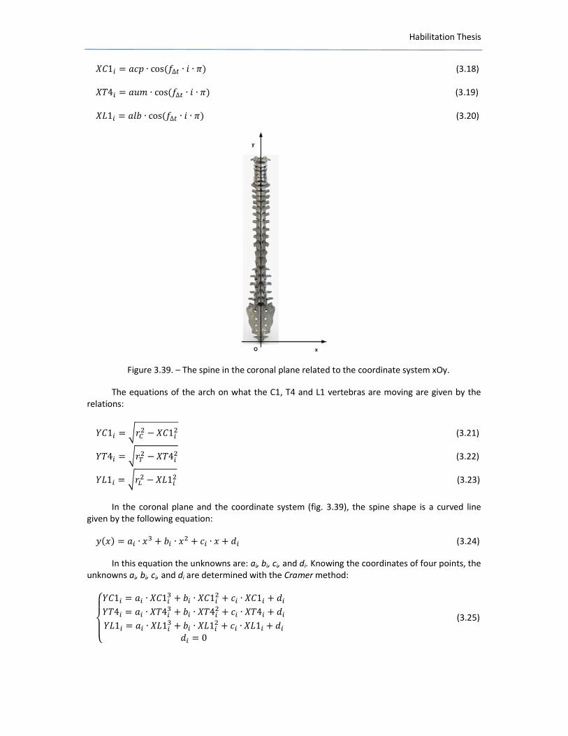
33 The drivers spine movement equation in the coronal planehelliphelliphelliphelliphelliphelliphelliphelliphelliphelliphelliphelliphelliphelliphelliphelliphelliphelliphelliphellip115
Habilitation Thesis
~ 2~
34Experimental determination of the intervertebral stresshelliphelliphelliphelliphelliphelliphelliphelliphelliphelliphelliphelliphelliphelliphelliphelliphelliphelliphelliphelliphelliphellip124
35 Modeling simulation and experimental determination of the spine muscles activities of the
driverhelliphelliphelliphelliphelliphelliphelliphelliphelliphelliphelliphelliphelliphelliphelliphelliphelliphelliphelliphelliphelliphelliphelliphelliphelliphelliphelliphelliphelliphelliphelliphelliphelliphelliphelliphelliphelliphelliphelliphelliphelliphelliphelliphelliphelliphelliphelliphelliphelliphelliphelliphelliphellip132
36 Human body posture before and after maxillofacial surgeryhelliphelliphelliphelliphelliphelliphelliphelliphelliphelliphelliphelliphelliphelliphelliphelliphelliphelliphellip140
II Academic and professional achievementshelliphelliphelliphelliphelliphelliphelliphelliphelliphelliphelliphelliphelliphelliphelliphelliphelliphelliphelliphelliphelliphelliphelliphelliphelliphelliphelliphelliphelliphelliphellip143
III Career evolution and development planshelliphelliphelliphelliphelliphelliphelliphelliphelliphelliphelliphelliphelliphelliphelliphelliphelliphelliphelliphelliphelliphelliphelliphelliphelliphelliphelliphelliphelliphelliphellip149
IV Referenceshelliphelliphelliphelliphelliphelliphelliphelliphelliphelliphelliphelliphelliphelliphelliphelliphelliphelliphelliphelliphelliphelliphelliphelliphelliphelliphelliphelliphelliphelliphelliphelliphelliphelliphelliphelliphelliphelliphelliphelliphelliphelliphelliphelliphelliphelliphelliphellip152
Habilitation Thesis
~ 3~
Abstract
The current thesis is the consequence of the authorrsquos research efforts during the 2000-2016
period at Politehnica University Timișoara being focused on 1 Constructive and functional
optimization of the mechanical face seals through modeling simulation and experimental work 2
Constructive and functional analysis of machine parts used in road vehicles 3 Modeling simulation
and experimental work on biological systems
This holds only a part of the research in mechanical systems design road vehicles design and
ergonomics during the time mentioned research that embedded diverse areas from analytical
modeling finite model modeling and experimental work to application fields such as road vehicles
ergonomics and medicine and maxillofacial ergonomics
In the recent years it has become more clear that the technical systems evolution is strongly
influenced by the outbreak from materials science domain advanced technologies information
technology and electronics and mechatronics
This allows the increase of research and optimizations in mechanical construction domain
Since the Phd thesis elaborated in 1998 the professional activities in the field of research and
education had the topics related to mechanical engineering flow and heat transfer in mechanical
face seals and ergonomics Until 2007 the topics were mostly in the field of mechanical engineering
specifically mechanical face seals joints clutches gears as a result of research contracts from the
national level (CEEX 21 I 0307102005 Research about the possibilities of using robotic systems
with the ai of increasing Romanian industry 361999 cod CNCSU 2041999 Means and methods for
mechanical transmissions and its components research Results implementation in education units
and economic units with industrial profile 361998 cod CNCSU 2801998 Means and methods for
mechanical transmissions and its components research Experimental research) international -FP7
2504852010 ThinkMotion or with private partners - SC ROSEAL SA and because the activity was
oriented in the machine design field ndashapplications and teaching construction and design of road
vehicles teaching
So this was the reason for making the experimental research The research results were
published in 6 ISI Journals 16 ISI Proceedings and IEEE Explore papers 39 in Scopus database 53 in
other database-Google (Scholar) Academic
The issues that were considered were
1 Constructive and functional optimization of the mechanical face seals through modeling
simulation and experimental work
11 ArgeșanuVPopaA The elastohydrodynamics (EHD) lubrification of a mechanical face
seal The revue of Tribology Fascicle VIII bdquoThe Annals of University Dunărea de Jos of
Galațirdquo ISSN 1221-4590 2004 pp 136 ndash 139
12 ArgeșanuVMădărasL Model and analysis of a Mechanical seal by Finit Element
Method Interface Tension Distribution Facta universitatis-series Mechanics Automatic
control and robots ISSN 0354-2009 2003 Vol 3 no 15
13 ArgeşanuVPopaA Interface contact pressure distribution in Dynamic contact face
seals analyzed by FEM 3rd International Conference With International Scientific
Comitee Research and Development in Mechanical IndustryRaDMI ISBN 86-83803-10-
4 2003
Habilitation Thesis
~ 4~
14 Argeșanu V Kulcsar RM Borozan IS Automotive Mechanical Face Seals Tribological
Simulation Journal of the Balkan Tribological Association ISSN 1310-4772 2011 Vol 17
no 1 pp 1 -12
15 Argeșanu V Kulcsar RMFarkaș IA Calculation by Finite Element Method(FEM) of
Temperature Distribution in the Components of a Mechanical Face Seal Journal of the
Balkan Tribological Association ISSN 1310-4772 2011 vol 17 no1 pp13-20
2 Constructive and functional analysis of machine parts used in road vehicles
21 Argeșanu V Luchin M Jula M Mărgineanu D Considerations Upon the Circular
Section CirclipsRetaining Rings Axial Load-Carrying Capacity ANNALS of DAAAM for
2008 amp Proceedings of the 19th International DAAAM Symposium ISBN 978-3-901509-
68-1 2008 pp 33-34
22 Argeșanu V Jula M Cărăbas I Determination of the Optimum Variant of Shaft-Hub
Joint for Gears ANNALS of DAAAM for 2009 amp Proceedings of the 20th international
DAAAM Symposium ISBN 978-3-901509-70-4 2009 vol 20 pp 1881-1882
3 Modeling simulation and experimental work on biological systems
31 ArgeșanuVKulcsar RMBorozan IS The drivers spine analytical model International
Journal of Biology and Biomedical Engineering ISSN 19984510 2014 vol 8 pp 172-178
32 Kulcsar RM Borozan IS Argeșanu V Experimental determination of the intervertebral
stress 12th IEEE International Symposium on Inteligent Systems and Informatics (SISY)
2014 pp 303-307
33 Streian F Argeșanu V Kulcsar RM Borozan IS Jula M Talpoș-Niculescu C
Human Body Posture before and after Maxillofacial Surgery Procedia Engineering ISBN
1877-7058 2014Vol 69 508-511
The first part refers to the optimization of the mechanical face seals from the point of view
of construction criteria and functioning the specific conditions concerning the environment and the
durability have a great impact on the construction of the mechanical equipment The complete
adjustment of all the types of mechanical seals implies additional anticorrosive and calorific
protection of the elastic pre-tensioned component the cooling of the surface which are in contact
and recirculation andor the evacuation of the discharge flow
A great diversity of contact-seals designs materials operating conditions and factor that
affect their performance have not yet allowed the general conclusions on friction and wear of these
seals to be drawn
The simple model of the complex friction between the surfaces in contact when taking into
account the hydrostatic theory of lubrication is functional both for convergent surfaces and for
divergent ones with the necessary particularities If the hydrostatic effect of lubrication is combined
with the mechanical effect of the solid contact with friction the problem of mixed friction that
appears at mechanical face seals can be solved Afterwards the hydrodynamic effect of lubrication
can also be introduced
There are various causes for face seal leaks Leakage normally takes place through the radial
seal gap formed by the two sliding surfaces Calculations are based on the assumption that a
hydrodynamic film exists in face seals and that the leakage can be calculated in accordance with the
known equations for laminar flow through a radial annular gap The form of the surfaces can
however Be altered by heating and wear for instance
Modeling to access solutions is the goal of predictive engineering The research deals with
the boundary element analysis or the numerical simulation of the behavior of a mechanical face
Habilitation Thesis
~ 5~
seal The present boundary element analysis is a particularly one for it contains the nonlinear effect
due to changes in boundary conditions resulting from the contact of the static ring and the sealing
head of the face seal These all have significant influence on the behavior of the system The results
can be used for optimizing designs predicting limits or investigating failures
In the second part the focus is on the constructive and functional analysis of machine parts
used in road vehicles
Some interesting aspects about the strength of helical gears are presented the beam
strength and the surface strength A lsquorsquominimum modulusrsquorsquo that guarantees the resistance of the gear
at both strength the beam strength and the contact strength as a lsquorsquoremedyrsquorsquo is proposed The PC is
utilized in order to ensure the arguments
The analysis is devoted primarily to the design of helical gears to resist bending failure of the
teeth and to resist pitting of failure of the tooth surface
the evolution of the constructive solutions of the joint that form the cylindrical fitting
specific to the gears determined the occurrence of some typified families whose carrying capacity
tend to equal the performances obtained by the joint by shrinking joints
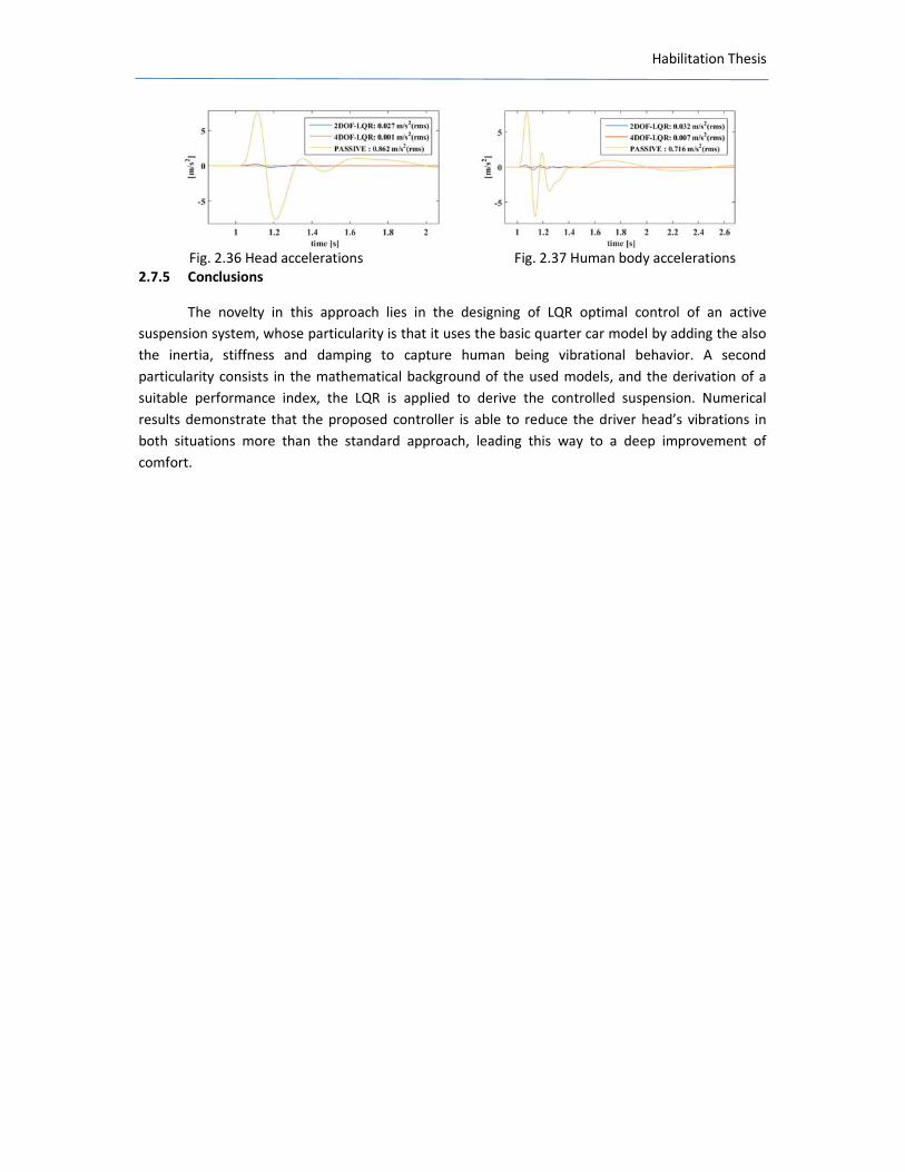
Experimental data regarding operational stats and thermal stats of an automatic gearbox are presented Experimental data regarding the operating pressure and the command of the solenoid actuators is being expressed in percentage and current is being recorded on the hydraulic test rig for establishment and optimization of the clutches and brakes operations from an automatic gearbox The purpose of the research is to point out a controlled vibration quarter car model of a
human body in seated position Its importance is mostly due to the vertical accelerations impact of
the human body and be able to control these vibrations It marks these vertical accelerations based
on a concentrated mass mathematical damped model This is first established mathematically and
then simulated in Matlab software its results clarifying the differences between accelerations at
different parts of the model and their range
The third part is about ergonomics as a human centered design and presents the candidate
contributions in the biological systems area This is the main area in which the candidate has made
the latest research as a result of research contracts at the national level- Manager- Contract
CNMPPNCDI 2 Nr 91-02218092007 ndash 2010 Workplace ergoengineering Dental medicine
applications or with enterprise partners-Honeywell researcher key-expert researcher in contract
AMPOSDRU 147724032010 ID 55651- Ergonomics prevention and performant management in
dental medicine by alignment to European standards CNMP PNCDI 2 no 41-03414092007
MICRODENT-Clinical protocols in dental microscopy applications CEEX 11604082006 with Medical
Science Academy Bucharest ndashStudies regarding the modular dental equipment based on
mechatronics systems ergonomic solutions for the double prevention of medical diseases CEEX
882006 ndashDevelopment and implement of performant systems of spine deformities on school
population and professional categories with sedentary lifestyle investigation and recovery the great
collaboration on national and international scale with SRED (Romanian Dental Ergonomics Society-
Societatea Romacircnă de Ergonomie Dentară) ndashfounding member and vicepresident ESDE (European
Society of Dental Ergonomics) specially with Prof Rotgans Jerome from Medical Faculty RWTH
Aachen University ndashthe president of ESDE and Chairman of the Study Group lsquoDental Ergonomicsrsquo of
the German Dental Association founding member and president of SRE (Ergonomic Romanian
Society -Societatea Romacircnă de Ergonomie-) and material base development through personal effort
Habilitation Thesis
~ 6~
Another contribution has been the involvement in POSDRU contract-Potebntial future PhD
leaders Contract AMPOSDRU2115G13798 Doctoral school in research aid through European
context ldquoȘcoala doctorală icircn sprijinul cercetării icircn context europeanrdquo in which I guided two doctorate
students As Dr Eng Kulcsar RaulndashMiklos (Ergonomic research regarding the spine behaviour during
the drive) and As Dr Eng Borozan Ion-Silviu (Automatic gearboxes parametric quality analysis
regarding the improvement of the technical and functional characteristics)
Habilitation Thesis
~ 7~
Rezumat
Teza curentă este urmarea eforturilor de cercetare ale autoarei din perioada 2000-2016 la
Universitatea Politehnica Timișoara fiind focalizată pe 1 Optimizarea funcțional constructivă a
etanșărilor frontale prin modelare simulare și icircncercări experimentale 2- Analiza funcțional-
constructivă a unor organe de mașini utilizate icircn autovehicule rutiere 3- Modelarea simularea și
icircncercarea experimetnală a sistemelor biologice
Aceasta constituie doar o parte a cercetărilor icircn construcția sistemelor mecanice a
autovehiculelor rutiere și ergonomie din această perioadă cercetare care a vizat diverse direcții de la
modelare analitică modelare cu element finit și icircncercări experimentale pacircnă la zone aplicative
precum ergonomia autovehciulelor rutiere și cea icircn domeniul medicinei dentare respectiv chirurgiei
maxilo-faciale
Icircn anii recenți a devenit din ce icircn ce mai evident că evoluția sistemelor tehnice este puternic
influențată de explozia noutăților din domeniul științei materialelor al tehnologiilor avansate al
tehnologiei informației și electronicii precum și cea din domeniul mecatronic
Aceasta obligă la a realiza cercetări și optimizări ale construcțiilor mecanice
De la elaborarea tezei de doctorat din anul 1998 activitățile profesionale icircn domeniul
cercetării și au avut ca bază domenii ale ingineriei mecanice curgeri și transfer termic ale etanșărilor
frontale și ergonomie Pacircnă icircn 2007 temele s-au axat mai mult icircn domeniul inginerie mecanice icircn
special etanșări frontale lagăre cuplaje angrenaje ca urmare a unor contracte de cercetare la nivel
național (CEEX 21 I 0307102005 Cercetări privind posibilitățile de utilizare ale sistemelor robotice
icircn scopul creșterii competivității tehnico-economice a industriei romacircnești 361999 cod CNCSU
2041999 Metode și mijloace pentru icircncercarea transmisiilor mecanice și a componentelor acestora
Etapa bdquoImplementarea rezultatelor cercetării icircn unități de icircnvățămacircnt și unități economice cu profil
industrialrdquo 361998 cod CNCSU 2801998 Metode și mijloace pentru icircncercarea transmisiilor
mecanice și a componentelor acestora Etapa bdquoCercetări experimentalerdquo) international -FP7
2504852010 ThinkMotion sau cu parteneri privați - SC ROSEAL SA și pentru că activitatea
didactică era orientată prioritar icircn domeniul ldquoorgane de mașinirdquo- predare aplicații construcția și cal
culul autovehiculelor rutiere-predare
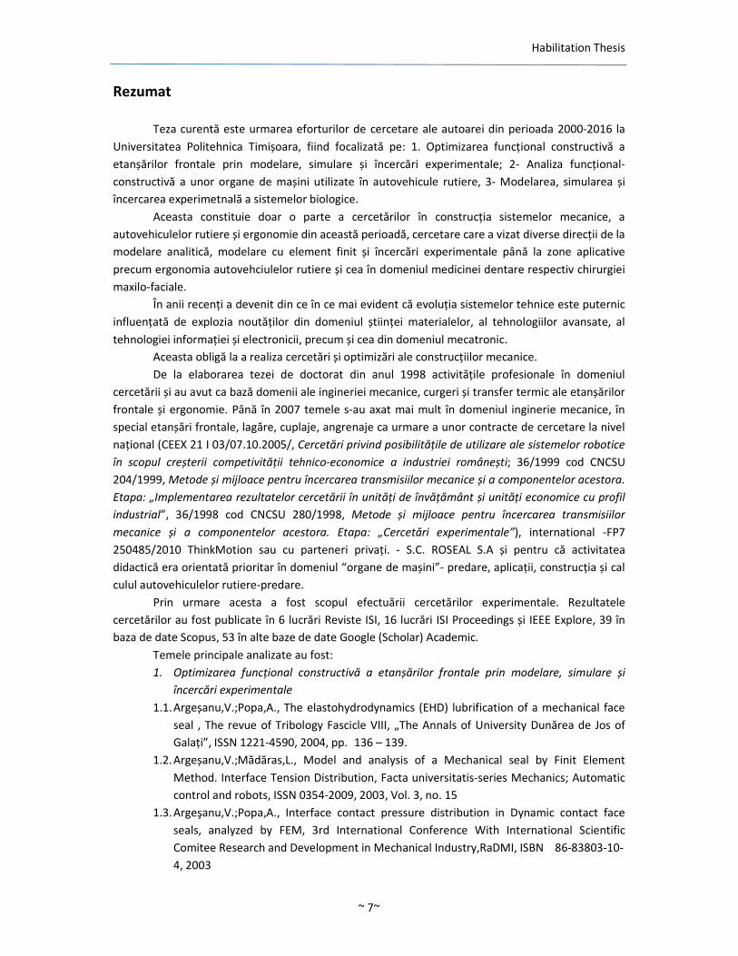
Prin urmare acesta a fost scopul efectuării cercetărilor experimentale Rezultatele
cercetărilor au fost publicate icircn 6 lucrări Reviste ISI 16 lucrări ISI Proceedings și IEEE Explore 39 icircn
baza de date Scopus 53 icircn alte baze de date Google (Scholar) Academic
Temele principale analizate au fost
1 Optimizarea funcțional constructivă a etanșărilor frontale prin modelare simulare și
icircncercări experimentale
11 ArgeșanuVPopaA The elastohydrodynamics (EHD) lubrification of a mechanical face
seal The revue of Tribology Fascicle VIII bdquoThe Annals of University Dunărea de Jos of
Galațirdquo ISSN 1221-4590 2004 pp 136 ndash 139
12 ArgeșanuVMădărasL Model and analysis of a Mechanical seal by Finit Element
Method Interface Tension Distribution Facta universitatis-series Mechanics Automatic
control and robots ISSN 0354-2009 2003 Vol 3 no 15
13 ArgeşanuVPopaA Interface contact pressure distribution in Dynamic contact face
seals analyzed by FEM 3rd International Conference With International Scientific
Comitee Research and Development in Mechanical IndustryRaDMI ISBN 86-83803-10-
4 2003
Habilitation Thesis
~ 8~
14 Argeșanu V Kulcsar RM Borozan IS Automotive Mechanical Face Seals Tribological
Simulation Journal of the Balkan Tribological Association ISSN 1310-4772 2011 Vol 17
no 1 pp 1 -12
15 Argeșanu V Kulcsar RMFarkaș IA Calculation by Finite Element Method(FEM) of
Temperature Distribution in the Components of a Mechanical Face Seal Journal of the
Balkan Tribological Association ISSN 1310-4772 2011 vol 17 no1 pp13-20
2 Analiza funcțional-constructivă a unor organe de mașini utilizate icircn autovehicule rutiere
21 Argeșanu V Luchin M Jula M Mărgineanu D Considerations Upon the Circular
Section CirclipsRetaining Rings Axial Load-Carrying Capacity ANNALS of DAAAM for
2008 amp Proceedings of the 19th International DAAAM Symposium ISBN 978-3-901509-
68-1 2008 pp 33-34
22 Argeșanu V Jula M Cărăbas I Determination of the Optimum Variant of Shaft-Hub
Joint for Gears ANNALS of DAAAM for 2009 amp Proceedings of the 20th international
DAAAM Symposium ISBN 978-3-901509-70-4 2009 vol 20 pp 1881-1882
3 Modelarea simularea și icircncercarea experimetnală a sistemelor biologice
31 ArgeșanuVKulcsar RMBorozan IS The drivers spine analytical model International
Journal of Biology and Biomedical Engineering ISSN 19984510 2014 vol 8 pp 172-178
32 Kulcsar RM Borozan IS Argeșanu V Experimental determination of the intervertebral
stress 12th IEEE International Symposium on Inteligent Systems and Informatics (SISY)
2014 pp 303-307
33 Streian F Argeșanu V Kulcsar RM Borozan IS Jula M Talpoș-Niculescu C
Human Body Posture before and after Maxillofacial Surgery Procedia Engineering ISBN
1877-7058 2014Vol 69 508-511
Prima parte se referă la optimizarea etanșărilor frontale din punctul de vedere al criteriului
de construcție și al funcționării acestora condițiile specifice de mediu și durabilitate avacircnd un impact
icircnsemnat icircn construcția de echipamente mecanice
Completa ajustare a tuturor tipurilor de etanșări frontale implică protecție anticorozivă și
calorică suplimentară a elementului elastic pretensionat răcirea suprafeței ce intră icircn contact și
recircularea șisau evacuarea fluxului evacuat
O mare diversitate a construcției și calculului etanșărilor de contacta materialelor
condițiilor de operare și a altor factori ce afectează performanța acestora nu au permis icircncă trasarea
concluziilor referitoare la frecare și uzură
Modelul simplu al complexității frecării dintre suprafețele aflate icircn contact atunci cacircnd se ia
icircn consderare teoria hidrostatica a lubrifierii este funcțională atacirct pentru suprafețe convergente cacirct
și divergente fiecare cu particularitățile aferente Dacă efectul hidrostatic al lubrifierii este combinat
cu efectul mecanic al frecării solide cu contact problema frecării mixte ce apare icircn cazul etanșărilor
frontalepoate fi rezolvată După efectul hidrostatic al lubrifierii poate fi deasemeni introdus
Există diverse cauze pentru scurgeri ale etanșărilor frontale Scurgerile au loc icircn mod normal
prin spațiul de etanșare radial format de cele două suprafețe de alunecare Calculele se bazează pe
presupunerea că există un film hidrodynamic icircn etanșrile frontale și că scurgerea poate fi calculată icircn
conformitate cu ecuațiile cunoscute de curgere laminară printr-un orificiu inelar radial Forma
suprafețelor pot cu toate acestea să fie modificate prin icircncălzire și uzură de exemplu
Modelarea pentru rezolvarea soluțiilor este obiectivul inginerie de predicive Cercetarea se
ocupă cu analiza elementului de delimitare sau simularea numerică a comportării unei etanșări
frontale Prezenta analiză cu element de delimitare este una deosebită pentru că ea conține efectul
Habilitation Thesis
~ 9~
neliniar datorită modificărilor condițiilor de delimitare care rezultă din contactul inelului static și
capul de etanșare a etanșării frontale Toate acestea au o influență semnificativă asupra
comportamentului sistemului Rezultatele pot fi utilizate pentru optimizarea cconstrucției și
calculului prezicere a limitelor sau monitoriarea eșecurilor
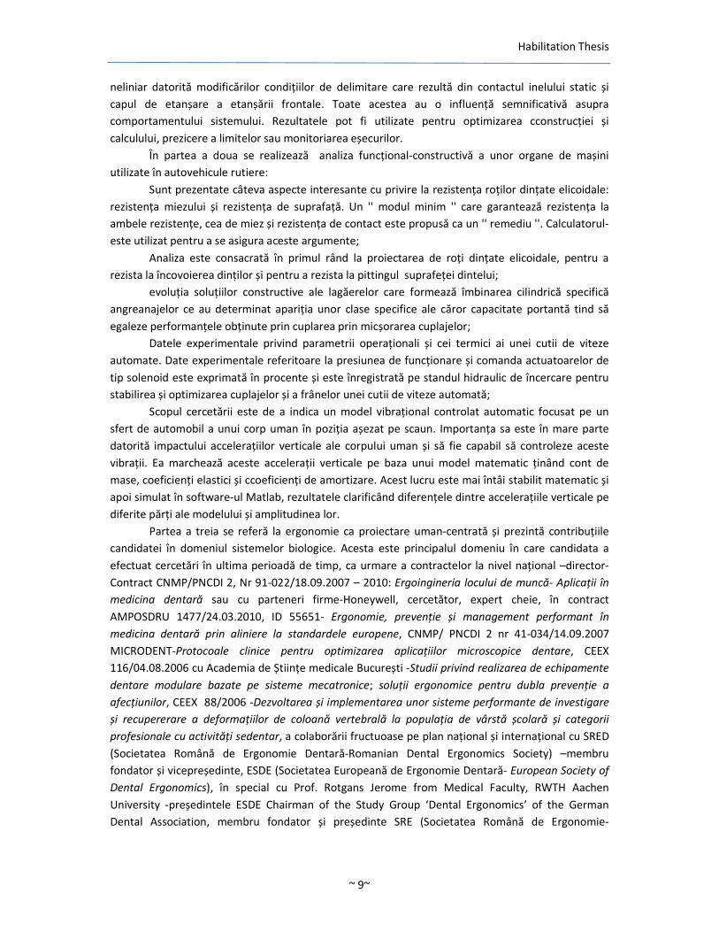
Icircn partea a doua se realizează analiza funcțional-constructivă a unor organe de mașini
utilizate icircn autovehicule rutiere
Sunt prezentate cacircteva aspecte interesante cu privire la rezistența roților dințate elicoidale
rezistența miezului și rezistența de suprafață Un modul minim care garantează rezistența la
ambele rezistențe cea de miez și rezistența de contact este propusă ca un remediu Calculatorul-
este utilizat pentru a se asigura aceste argumente
Analiza este consacrată icircn primul racircnd la proiectarea de roți dințate elicoidale pentru a
rezista la icircncovoierea dinților și pentru a rezista la pittingul suprafeței dintelui
evoluția soluțiilor constructive ale lagăerelor care formează icircmbinarea cilindrică specifică
angreanajelor ce au determinat apariția unor clase specifice ale căror capacitate portantă tind să
egaleze performanțele obținute prin cuplarea prin micșorarea cuplajelor
Datele experimentale privind parametrii operaționali și cei termici ai unei cutii de viteze
automate Date experimentale referitoare la presiunea de funcționare și comanda actuatoarelor de
tip solenoid este exprimată icircn procente și este icircnregistrată pe standul hidraulic de icircncercare pentru
stabilirea și optimizarea cuplajelor și a fracircnelor unei cutii de viteze automată
Scopul cercetării este de a indica un model vibrațional controlat automatic focusat pe un
sfert de automobil a unui corp uman icircn poziția așezat pe scaun Importanța sa este icircn mare parte
datorită impactului accelerațiilor verticale ale corpului uman și să fie capabil să controleze aceste
vibrații Ea marchează aceste accelerații verticale pe baza unui model matematic ținacircnd cont de
mase coeficienți elastici și ccoeficienți de amortizare Acest lucru este mai icircntacirci stabilit matematic și
apoi simulat icircn software-ul Matlab rezultatele clarificacircnd diferențele dintre accelerațiile verticale pe
diferite părți ale modelului și amplitudinea lor
Partea a treia se referă la ergonomie ca proiectare uman-centrată și prezintă contribuțiile
candidatei icircn domeniul sistemelor biologice Acesta este principalul domeniu icircn care candidata a
efectuat cercetări icircn ultima perioadă de timp ca urmare a contractelor la nivel național ndashdirector-
Contract CNMPPNCDI 2 Nr 91-02218092007 ndash 2010 Ergoingineria locului de muncă- Aplicații icircn
medicina dentară sau cu parteneri firme-Honeywell cercetător expert cheie icircn contract
AMPOSDRU 147724032010 ID 55651- Ergonomie prevenție și management performant icircn
medicina dentară prin aliniere la standardele europene CNMP PNCDI 2 nr 41-03414092007
MICRODENT-Protocoale clinice pentru optimizarea aplicațiilor microscopice dentare CEEX
11604082006 cu Academia de Științe medicale București -Studii privind realizarea de echipamente
dentare modulare bazate pe sisteme mecatronice soluții ergonomice pentru dubla prevenție a
afecțiunilor CEEX 882006 -Dezvoltarea și implementarea unor sisteme performante de investigare
și recupererare a deformațiilor de coloană vertebrală la populația de vacircrstă școlară și categorii
profesionale cu activități sedentar a colaborării fructuoase pe plan național și internațional cu SRED
(Societatea Romacircnă de Ergonomie Dentară-Romanian Dental Ergonomics Society) ndashmembru
fondator și vicepreședinte ESDE (Societatea Europeană de Ergonomie Dentară- European Society of
Dental Ergonomics) icircn special cu Prof Rotgans Jerome from Medical Faculty RWTH Aachen
University -președintele ESDE Chairman of the Study Group lsquoDental Ergonomicsrsquo of the German
Dental Association membru fondator și președinte SRE (Societatea Romacircnă de Ergonomie-
Habilitation Thesis
~ 10~
Ergonomic Romanian Society) și a dezvoltării bazei materiale necesare cercetării prin eforturile
proprii ale autoarei
De asemenea o contribuție hotăracirctoare a avut-o implicarea icircn POSDRU Potențiali viitori
conducători de doctorat Contract AMPOSDRU2115G13798 ldquoȘcoala doctorală icircn sprijinul
cercetării icircn context europeanrdquo icircn cadrul căruia am tutoriat doi doctoranzi pe As Dr Ing Kulcsar
RaulndashMiklos (Cercetări ergonomice asupra comportării coloanei vertebrale a conducătorului auto-
Ergonomic research regarding the spine behaviour during the drive) și As Dr Ing Borozan Ion-Silviu
(Determinarea parametrilor cutiilor de viteze automate icircn scopul icircmbunătăţirii caracteristicilor
tehnico-funcţionale ale acestora -Automatic gearboxes parametric quality analysis regarding the
improvement of the technical and functional characteristics)- cu teze icircn domeniul cutiilor de viteze ndash
gears și ergo-autovehicule (Contract AMPOSDRU2115G13798)
Habilitation Thesis
~ 11~
I Scientific achievements
1 Constructive and functional optimization of the mechanical
face seals through modeling simulation and experimental
work
11Basic topics of mechanical seals
111 Introduction
The specific conditions concerning the environment and the durability have a great impact
on the construction of the mechanical equipmentThe complete adjustment of all the types of
mechanical seals implies additional anticorrosive and calorific protection of the elastic pre-tensioned
component the cooling of the surface that is in contact and recirculation andor the evacuation of
the discharge flow The study takes into consideration all the factors regarding the selection and
disposal of all the elements that are used in the construction of mechanical seals
The constructive diversification of mechanical seals to a couple of materials according to
their destination depends directly on the allowed speed range on the pressure inside the sealed
space and on the way in which the hydrostatic trimming of the two rings was made and finally
depends on the operating economic course of activity[3][5]
The complete adjustment of all the types of mechanical seals implies additional anticorrosive and
calorific protection of the elastic pre-tensioned component the cooling of the surface that are in
contact and re-circularization andor the evacuation of the discharge flow All the functional and
constructive condition mentioned above have led to the generation of facility thermal seals which
starting from basic elements like rings archers that vary from a wide range that covers various
particular requirements
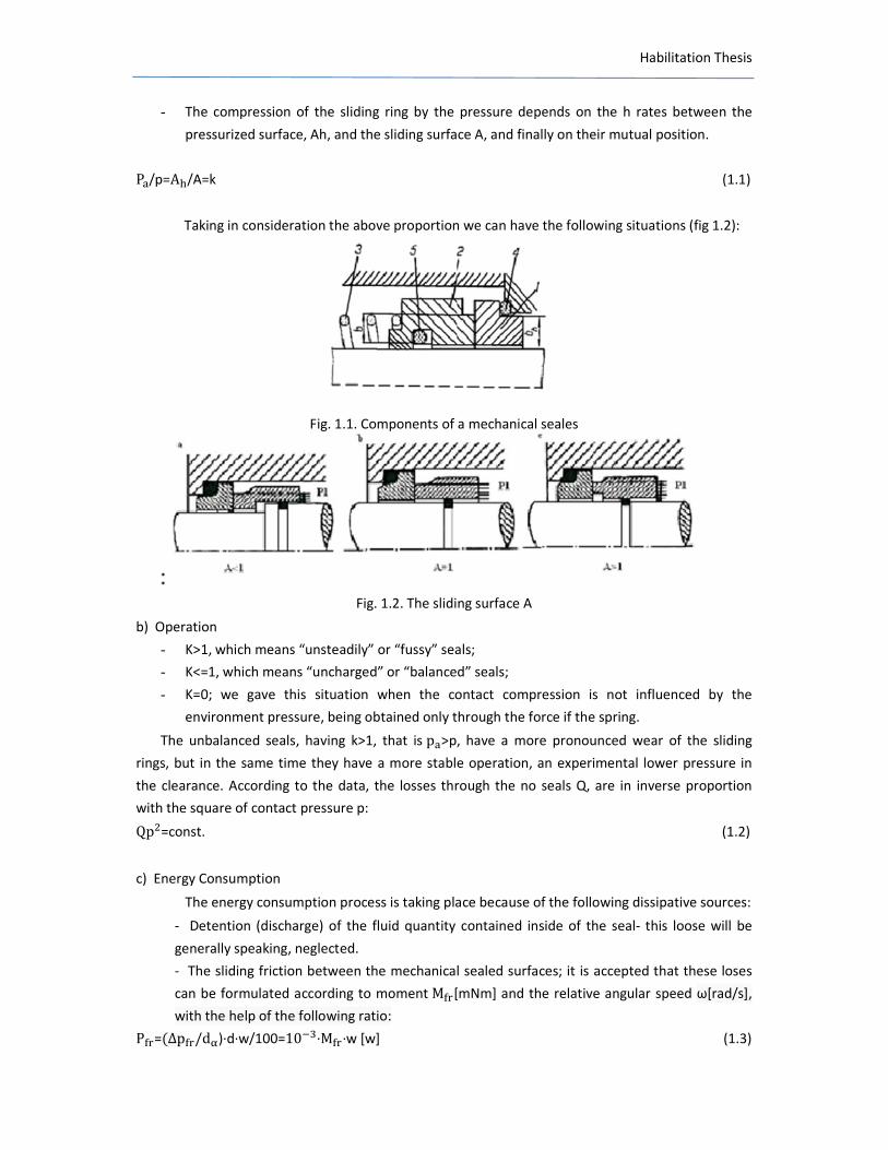
112 Construction and operation
a) Construction
A mechanical seals is made mainly from the following components (fig 11)
- A stationary ring (1) and a sliding one with a relative rotation movement (2) one of these
rings allowing the axial movement on the shaft compensation of the wear
- A system of reciprocal pressing system of the two rings ndash represented in the figure by the
cylindrical spring (3) and by the seals represented by the two ldquoordquo rings immobile towards the
sheaf and the housing
- The average dimension of the realized clearance h and the axial force verso pressing force F
determine a certain pressure behavior inside the clearance that has an influence on
lubrication of the contact surfaces their durability and tightness
Habilitation Thesis
- The compression of the sliding ring by the pressure depends on the h rates between the
pressurized surface Ah and the sliding surface A and finally on their mutual position
Pp=AA=k (11)
Taking in consideration the above proportion we can have the following situations (fig 12)
Fig 11 Components of a mechanical seales
Fig 12 The sliding surface A
b) Operation
- Kgt1 which means ldquounsteadilyrdquo or ldquofussyrdquo seals
- Klt=1 which means ldquounchargedrdquo or ldquobalancedrdquo seals
- K=0 we gave this situation when the contact compression is not influenced by the
environment pressure being obtained only through the force if the spring
The unbalanced seals having kgt1 that is pgtp have a more pronounced wear of the sliding
rings but in the same time they have a more stable operation an experimental lower pressure in
the clearance According to the data the losses through the no seals Q are in inverse proportion
with the square of contact pressure p Qp=const (12)
c) Energy Consumption
The energy consumption process is taking place because of the following dissipative sources
- Detention (discharge) of the fluid quantity contained inside of the seal- this loose will be
generally speaking neglected
- The sliding friction between the mechanical sealed surfaces it is accepted that these loses
can be formulated according to moment M[mNm] and the relative angular speed ω[rads]
with the help of the following ratio P=Δpd)∙d∙w100=10∙M∙w [w] (13)
Habilitation Thesis
~ 13~
The friction moment that appears at the mechanical seal represents the amount between
the moment of friction of the contact surfaceM and the moment due to the movement of the seal
into the fluid M M = π∙ D2 ∙ b ∙ p∙micro (14)
The moment M is important it has a bad influence on the thermic charging of sealing and
wear of the rings The component M has a great importance at high speeds having a positive
influence generally having a cooling effect
M = π∙D2 ∙ b∙p∙micro (15)
This last loss will be determined in all the cases The designer has the opportunity that
through the discharge effect to influence the value of p and therefore this loss The contracted ring
determines a smaller loss but is a disadvantage by representing a greater danger of braking
Estimating the losses though the non-sealing we can have the following situations
- the conditions of mixed friction in the annular tumble
Q = π ∙ d ∙ (p-p) ∙ h ∙ Sp (16)
S=interface factor
- mixed friction conditions in the annular thimble
Q=c ∙ π ∙ d (p minus p) ∙ η ∙radicvbp (17)
- fluid friction conditions in the annular thimble
Q=c ∙ π ∙ d (p minus p) ∙ ampηbvp (18)
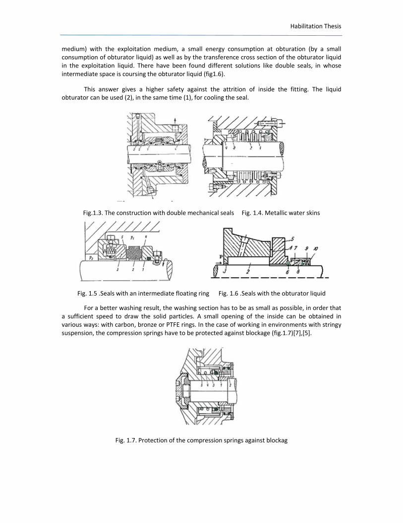
The abstraction of the heat is made more often by the sealed medium excluding the vaporization process in the interstice The temperature arising inside the interstice is a consequence of the heating produced through the friction and may produce pronounced detritions the aerate of the lubricant film that will result in to a that fast growing of friction coefficient and of detritions in some cases the exceeding of the integration temperature of materials which can lead as well to a thermic breaking of the rings reciprocal slider of thermal palling Taking in consideration all the condition mentioned above we can say that rings made of materials with a high thermal conductivity may have a better behavior in connection with the thermic aspects The seals used for high temperature have to be reared as much as possible the temperature from interface is being kept under the critical temperature of vaporization in order to prevent the appearance of dry friction anticipating for example (fig13) the construction with double mechanical seals In case the maximum temperature passes the sensitive point of the elastomeric components of the seal then we have to use metallic water skins (fig14) having the advantage of a small axial gauge higher capacities of loading and better flexibility characteristics[1][2][4] Regarding the seals for a higher speed of the shafts of the pumps compressors or turbines the springs are fixed on the armature or we use seals with an intermediate floating ring (fig15) Secondly it becomes necessary to mix as less as possible the obdurate liquid (a fluid oil with a pressure greater than that of the exploitation
Habilitation Thesis
medium) with the exploitation medium a small energy consumption at obturation (by a small consumption of obturator liquid) as well as by the transference cross section of the obturator liquid in the exploitation liquid There have been found different solutions like double seals in whose intermediate space is coursing the obturator liquid (fig16)
This answer gives a higher safety against the attrition of inside the fitting The liquid obturator can be used (2) in the same time (1) for cooling the seal
Fig13 The construction with double mechanical seals Fig 14 Metallic water skins
Fig 15 Seals with an intermediate floating ring Fig 16 Seals with the obturator liquid
For a better washing result the washing section has to be as small as possible in order that a sufficient speed to draw the solid particles A small opening of the inside can be obtained in various ways with carbon bronze or PTFE rings In the case of working in environments with stringy suspension the compression springs have to be protected against blockage (fig17)[7][5]
Fig 17 Protection of the compression springs against blockag
Habilitation Thesis
~ 15~
113Conclusion
In conclusion the particulars that appear in seal problems the constructive solutions the
right choosing of materials as well as the usage of special made accessories lead to the
diversification of seals types taking in consideration the functional aspects as well as those of safety
in exploitation
12 Lipseals and mechanical face seals performance criteria
121 Introduction
A great diversity of contact-seals designs materials operating conditions and factor that
affect their performance have not yet allowed the general conclusions on friction and wear of these
seals to be drawn At the same time the results of studies of particular cases may often lead the
design engineer to an erroneous decision if the seal he develops is different in some way from that
he has taken as a prototype To a face seal design choice of materials and type of seal arrangement
individual requirements such as minimum leakage maximum life or minimum friction can be
met[68][69]
Labyrinths stuffing boxes lip seals bushings spiral-groove seals and mechanical seals made
out of a very large number of materials are the systems that are commonly used for sealing rotating
shafts [64] The behavior of a seal is determined by the complex interaction of a number of factors
Advantages are usually attained at the price of disadvantages in the order directions For example if
the roughness is constant an increase of the contact pressure reduces leakage but the wear and
frictional heat increase As against this increasing leakage losses can reduce the friction and the heat
production but the effectiveness of the unit as a seal is reduced Again a high friction may not only
lead to increased wear but also due a thermal distortion to considerable leakage losses or it may
cause the seal to break down because of a thermal stress cracks [56][57]
Depending on application sealing rubber should be strong heat resistant cold resistant or
resistant to chemical attack The characteristics must often be combined some of them are mutually
incompatible Anyhow all sealing rubber applications require good friction properties high wear
resistance and low coefficient of friction
122 Friction and wear in dynamic contact seals
The performance of seals is characterized by the degree of tightness service life power
losses by the extent of damage to the contacting surface in operation etc the degree of tightness
wear life tw and performance factor I are the most important characteristics of seal
performance[9][65][79]
In addition to the above factors temperature whose level is determined by their joints
action also affects the performance of dynamic seals Whereas temperature has the major influence
Habilitation Thesis
on the frictional effects in the contact area the leakage is caused by reduction in the contact area
pressure and distortions in the geometry of the rubbing surface due to wear (fig18ab) increased
thermal deformations etc In some instances these factors are interdependent [46] The service
conditions of sliding contact seals in machinery determined by combinations of the above factors
are very diverse In a face seal (fig19) an axial force pressed a rotating floating ring 5 against a fixed
counter face 6
Fig18a Lipseal Fig18b PTFE lip seal
Fig19 Mechanical face seal
The axial leakage path between the floating ring and the shaft is closed by a static seal such
as an O-ring 7[5][37][53]The static and sliding surface of the traditional stuffing box are effectively
interchanged with the advantage than the geometry if the sliding sealing surface can now be
produced more accurately and less expansively and there is no longer any wear on the shaft or shaft
sleeve[10][52] To compensate for any lack of alignment of the seal faces and for longitudinal
thermal expansion of machine and seal as well as wear of the seal faces the face seal must contain
at least one flexible member such as diaphragm bellows elastomeric seal or springs
13(fig19)[9][72]
In selecting sliding materials consideration should be given to operating conditions ease of
manufacture and material costs The chemical activities as well as the physical and mechanical
properties have to be considered By selecting materials with appropriate thermal conductivity
coefficients by additional cooling lubrication and load ldquobalancingrdquo
The sealing medium also has a considerable influence on the life of a mechanical seal
Mounting seals on elastomeric rings has a very beneficial effect on wear because of damping actions
of the elastomer Often the durability of a seal is determined not by the wear of the seal alone but
by the resistance of ageing of any elastomers used Intermittent operation as well as increases of
contact pressure friction coefficient sliding speed and temperature will reduce the life Since the
effects of adhesive wear abrasive wear corrosive wear and erosive wear let alone vibration
Habilitation Thesis
~ 17~
temperature and material effects can be cumulative If it defines the intensity of the power lost by
friction in the area of contact as the ratio of the power lost by friction and land sliding [51][38][10]
() +- = ∙ 01 ∙ 2) (19)
Where micro - friction coefficient in the contact area
01 - pressure in the area of contact
v - relative speed
This may give an appreciation of the value limit of operating of the sealing If we consider for
example micro=01hellip03 for PTFE lip seal or micro=0005hellip01 for the elastomer lip seal the pressures of work
of 3MPa sliding speeds of 12ms () +- =36 Wmm2 for PTFE and
() +- =72Wmm2 for
elastomers
123 Performance criteria
A comparative situation between the face seals and lip seals based on technological
operational and cost is presented in tab11 When comparing the values it must be borne in mind
that the sealed pressure p1 for lip seals are lower that the corresponding mechanical seals
Despite this it is evident that on account of smaller leakages of the buffer fluid and sealed
product and greater operational safety and reduced maintenance mechanical seals are much
superior to lip seals
Whereas the initial prices of the lip seals are lower than those of the face seals the position
is reverse upon installation and putting into operation The labor-intensive maintenance costs are
about 20 times higher with leap seals Despite the more expensive spare parts for mechanical seals
their total costs comes lower than for lip seals on account of the long life of the former[39][12]
It also is taken into account that due to labor savings smaller leakage losses greater
operational safety and reduced-down time face seals are even more economical than would
appear
By means of a metallic support jacket in the carbon ring which is certainly deformed much
more than the tungsten carbide seal under high pressure loads because of its low modulus of
elasticity the previous very good operating characteristics of conventional thermo hydrodynamic
seals could be further improved at higher pressure
In seals with the stabilized seal gap the hydrodynamics of the circulations grooves are a
better design Seals gap are much less sensitive to pressure changes and have even longer service
lives
Habilitation Thesis
124 Conclusion
The behavior of a seal is determined by the complex interaction of a number of factors
Advantages are usually attained at the price of disadvantages in the order directions
If we compare specific losses through friction in the usual pressure for lip seals ldquounchargedrdquo or classical ldquochargedrdquo with 3 = 45 6 ∙ 78 (110)
Face seals we can notice the net advantage of helip seals these having as a plus size and lower
costs However in the field of higher speed and pressure and for hard working environments the
face seals are still irreplaceable (fig 110)
Tab11Performance parameters of seals
Fig110 Specific friction losses function pressure dependency for different types of seals
Habilitation Thesis
13 The flowing-friction dependency at a mechanical face seal
131 Introduction
It is presented the simple model of the complex friction between the surfaces in
contact[43][44][45] when taking into account the hydrostatic theory of lubrication is functional
both for convergent surfaces and for divergent ones with the necessary particularities If the
hydrostatic effect of lubrication is combined with the mechanical effect of the solid contact with
friction the problem of mixed friction that appears at EF can be solved Afterwards the
hydrodynamic effect of lubrication can also be introduced[50][14][58]
From the constructive and functional point of view the frontal tightening realizes the closing
of a premise with a tribologic couple of a fourth class (plane surface couple)[5][59][42][60]
The ring (6) (see Figure 111) is immobilized in ratio with the case and constitutes the
element of friction The ring (5) which is in a forced frontal contact with the first one has the role of
a pressure clement and is rotating with the shaft We thus observe that on the grounds of
constructive vicinity the tightening function in this case is distributed on two levels The first level is
the primary tightening assured through the forced and direct contact between the two rings with
relative motion
Habilitation Thesis
Fig 111
The second level is the secondary tightening represented in the tightening packing of the two rings over the shaft and over the case and forbids the escape on the motionless contact areas with the conjugated pieces(the bearings lid and the shaft)
We observe that in this way the solution may give very high performances suitably
influencing every zone The advantage of separating the functions may consist of
- the lightening with direct contact becomes prevalent abrasive worn out and thus its
replacement is conditioned by the evolution and the advance of this process At tightening
on cylindrical surfaces the compensation of wear on radial direction involves the elasticity
of the contact while at frontal contact a simple axial shift in an interval large enough
preservesrebuilds in natural way (compensates) the tightening function Secondary
tightening acts on cylindrical surfaces but their relative immobility does not lead to
significant wear only in cases of electrochemical and contact corrosions or mechano-
chemical (tribo-chemical) corrosion which might be diminished a lot by using additives of
extreme pressure and anti-wear protection covers of the surfaces and a suitable choice of
the couple of materials
- the work way of a frontal tightening is based upon the existence of an axial resultant force
which has as an effect the pressing of the slipping ring which can shift in axial way on the
other ring and between the ring-shaped contact surfaces a very small clearance is realized
capable of realizing the tightening
This axial force is the resultant of the following components applied to the ring
132 The hydrostatic flowing of the fluid through the clearance of the ring-shaped couple
of a mechanical face seal
Theoretically speaking mechanical face seal may be assimilated with a ring-shaped friction
couple with rigid and impermeable active faces having a good smoothness low roughness Between
the faces there is always a thin and continuous film of hydrostatic Newtonian fluid [40][41][35] in
rolling flowing
Habilitation Thesis
Fig 112
With the notations in Figure 112 we may write
The motion equations
(111)
(112)
The continuity equation
(113)
For solving the system of equations we put the conditions at limit
The kinematics limit conditions
(114)
The limit conditions for pressures
(115)
and by taking the viscosity constant the equations become
The motion equations
rv p
x x rη
partpart part = part part part
0v
x x
ϕηpart part
= part part
0r rv v
r r
part+ =
part
0 0 0
0
r
r
z v v
z h v v r
ϕ
ϕ ω
= = =
= = = sdot
1
1 2
er r p p
r r p p
= =
= =
Habilitation Thesis
~ 22~
(116)
The continuity equations
(117)
This system of equations allow the analytic determination of the speed and pressures
distribution in the film of fluid when considering the same limit conditions
(118)
(119)
(120)
In the case of small widths of clearance in ratio with the ray the pressures distribution may
be considered linear
The force in the clearance that tries to undo the tightening (in the hypothesis of a Poiseuille
flowing)
(121)
And the flowing that will escape through tightening
(122)
The moment of friction in the clearance will be established with the relation
(123)
And the coefficient of friction has the value
(124)
Where
22
2 2
1 0r
vv p
x r x
ϕ
η
partpart part= sdot =
part part part
( )1
2r
dv x x h
dr
ϕη
= sdot sdot minus
rv x
hφ
ω=
12 1 2
1
ln ln( )
ln lne
r rp p p p
r r
minus= + minus
minus
2 22 2 1
1 2 1 1 2
1
( )( ) ( )
2ln
ehs e
e
r rF p r p r p p
r
r
ππ
minus= minus + minus
31 2
16 ln lne
p phQ
r r
πη
minus= sdot
minus
4 422
2
e
i
r
e ifr
r
r rrM r dr
h h
ω πηωπ η
minus= =int
fr
m
M
F rmicro =
sdot
0
vr vr
r
part+ =
partr
Habilitation Thesis
~ 23~
rm=9
The power consumption lost through friction has the value
(125)
The simple model of the complex friction between the surfaces in contact when taking into
account the hydrostatic theory of lubrication is functional both for convergent surfaces and for
divergent ones with the necessary particularities
133 Conclusions
Theoretically speaking mechanical face seal may be assimilated with a ring- shaped friction
couple with rigid and impermeable active faces having a good smoothness low roughness Between
the faces there is always a thin and continuous film of hydrostatic Newtonian fluid in rolling flowing
If the hydrostatic effect of lubrication is combined with the mechanical effect of the solid
contact with friction the problem of mixed friction that appears at EF can be solved
Afterwards the hydrodynamic effect of lubrication can also be introduced
14 The elastohydrodynamic (EHD) lubrication of a
mechanical face seal
141 Introduction
There are various causes for face seal leaks Leakage normally takes place thru the radial seal
gap formed by the two sliding surfaces [86] Calculations are based on the assumption the a
Hidrodynamic film exists in face seals and that the leakage can be calculated in accordance with the
known equations for laminar flow thru a radial annular gap The power consumption can be
calculated also from the Newton relation Normally mechanical seals have radial rigid plain faces and
only in special cases do spherical sealing surfaces occur [74] The form of the surfaces can however
be altered by heating and wear for instance
There are various causes for face seal leaks Leakage normally takes place through the radial
seal gap formed by the two sliding surfaces Only the primary leakage through the seal gap between
the faces of the seals will he considered since in practice the liquid film thickness h is seldom
constant and the actual gap form can considerably deviate from the assumed parallel gap because of
temperature differences in the ring[63] deviations Earn the theoretical calculations are to be
expected
In addition to the mechanical forces different temperatures and their gradients also
influence the geometry of the seal gap In the case of elastic distortion the magnitude of the elastic
modules and the dimensions of the rings are the determining factors and in thermal distortions it is
( )2
4 4
2fr fr e iP M r rh
π ηωω= sdot = sdot sdot minus
Habilitation Thesis
~ 24~
the values of the thermal properties of the materials and the heat transfer factors in conjunction
with the construction of the rings which influence the temperature gradients and in him the gap
shape The temperature gradient in both axial and radial directions influences the geometry of the
seal gap
In mechanical seals there are often several heat sources which strongly influence the radial
temperature distribution in the rings In addition to the friction heat from the sliding interface the
medium to be sealed may be a source of heat as well as a hot shaft or housing[70] and heat from
liquid turbulence
Depending on the direction of the temperature gradient the temperature distribution in the
sealing rings can considerably differ [71] Those areas of the rings that lie furthest hour the heat sink
or are nearest to the source of heat show the highest temperatures They expand to a mater extend
then other sectional areas and alter the shape of the original parallel film gap
In face seals the contact points of the asperities on the two Seals surfaces pressed against
one another with an average pressure could distort both plastically and elastically Thus the most
highly stressed bearing palms will be distorted plastically or worn away while the neighboring areas
will be elastically distorted In the usual combinations of materials for face seals 3 carbon graphite
ring is usually run against a metal metal oxide or carbide ring with different elastic modules
Since the surfaces is always highly finished the low modules ring will always take a
considerably greater proportion of distortion For these reason the sliding surfaces under load will
look more like an aerial photograph of a group of lakes then of a group of islands the hollow Spaces
between the surfaces are seldom connected to one another With the rotation of one ring it is
possible to imagine that the liquid is transported from one hollow to another as in the case of a
revolving door until the liquid particles emerge at the far side of the gap Thus in this range there
will be no detectable influence of Viscosity As long as liquid inflow and outflow counterbalance each
other no pressure builds up in the interface Where roughness of the sliding surfaces is uniform the
leakage losses with an exchange flow are independent of the seal width but strongly dependent on
the value of the roughness the closing pressure the rubbing speed and the sine and direction of
the centrifugal pressure Furthermore the inflow and outflow sections of the sliding rings could
influence the leakage [61]
On the other hand non-homogeneous materials can form microscopic ridges and pits due to
differing coefficients of heat conduction and expansion and the differing local frictional heating
Localized contact points expand due to heating and form small oil wedges The
hydrodynamic pressure produced will reduce interface friction by thermomdashhydrodynamic effect
Hydrodynamic effects can also be observed with slightly porous material such as ceramics
provided that the pores are not intercommunicating for them no pressure rise is possible The
depressions formed by the pores in turn produce localized grease cups and pressure fields However
with increasing mean sliding pressure the carbon being less elastic is pressed into these pores and
displaces the fluid at greater loads the carbon particles share off with consequent high wear With
carbon against ceramic deposits of carbon can nearly always be observed on the ceramics rings and
heavy wear is noticeable
Habilitation Thesis
~ 25~
Thermodynamic effects depend on adequate temperature differences Fluid of good heat
transfer coefficients like water for instance increase the effect
142 The end lubrification
The existence of a film of a lubricant in the seal gap and of a circumferential debit in a
Couette flow will take to the appearance of a EHD sustentation caused in the case of a mechanical
face seal to the Irregularities of the sliding surfaces undulations pores thermal deformations etc
and in case of an special mechanical face Seal by the adequately manufacture on the
interface[15][16][17]
The high-speed mechanical face seal must work with full film lubrication to ensure an
acceptable operation life so that although there is a sealing system the functional characteristics
are the same as of any friction fluid couple
-the axial opening force
- the stiffness of the film
-the leakage fluid flow thru the sealrsquos interface gaps
- the friction moment
The elastohydrodynamic lubrication is based in the context of the following working
hypothesis between two rigid sliding surfaces G) a stationary isotherm and incompressible (which
viscosity varies only with the temperature η(T)) Newtonian fluid is laminar flowing
Since the height of the condoning and stable coating of the lubricant is very reduced in
relation with the other dimensions the flow can be considered biaxial
The elasto-hydrodynamic lubricant regime appears in ordinary friction couples because of
the undulations on the sliding sun-faces or because of pressureforcetemperature defamation (fig
113)
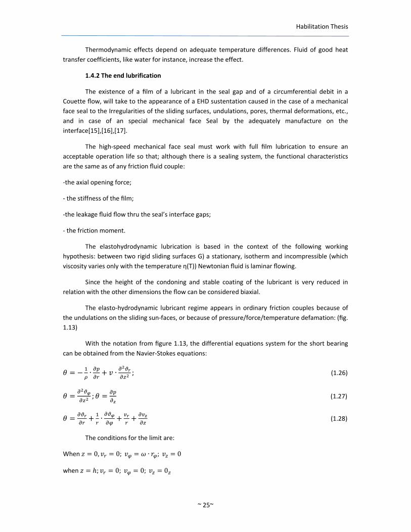
With the notation from figure 113 the differential equations system for the short bearing
can be obtained from the Navier-Stokes equations
3 = minus lt ∙ =gt= + 2 ∙ =AB=C (126)
3 = =AE=C 3 = =gt=F (127)
3 = =AB= + ∙ =AE=G + HB + =HF=C (128)
The conditions for the limit are
When I = 0 2 = 02G = K ∙ LG2C = 0
when I = ℎ 2 = 02G = 02C = 0C
Habilitation Thesis
when L = L 0 = 0 (129)
when L = L 0 = 0NOP7ℎ = ℎQ)
Fig 113 Calculus model for an ondulated surface andthe other plane[13][5]
The liquid presure in the lubricant film is
0 = R ∙ K ∙ STBBU ∙ VL ∙ ln U minus L ∙ ln U minus L ∙ ln UY ∙ Z[ ∙ 1Z1G + gtgt])∙ST BBUSTBBU (130)
where h is the thickness of the clearance
The radial component of the flowing speed is
2 = minus^_ ∙ K ∙ STBBU V2 ∙ L ∙ ln U + U Y ∙ Z[ ∙ 1Z1G + gtgt])∙`∙STBBU ∙ a ∙ ℎC minus I) (131)
Relation (130) shows that in the conditions of a continuous film the total hydrodynamic
force of the couple of the friction is zero if we consider that in some areas of the space between the
sliding rings they appear cavity zones of the lair then for a surface with a big number of
undulations the hydrodynamic force is
4 = b ∙ R ∙ K ∙ V ZU minus ZY cL minus L minus L + L) ∙ ln Ud ∙ USTBBU (132)
where ℎ and ℎ are the minimum and maximum clearance magnitude
The friction moment calculated in the conditions of the continuity of the lubricant film in the
clearance is
e = _ ∙ R ∙ K ∙ L_ minus L_) ∙ f 1GZgh (133)
The leakage flow trough the radial annular gap is
i = j∙gtgt])∙`∙U∙STBBU ∙ f ℎ ∙ 7 ∙ QGkh (134)
where Qhis the angle that contains the parts of the acting were the thiknes is reducing
Habilitation Thesis
~ 27~
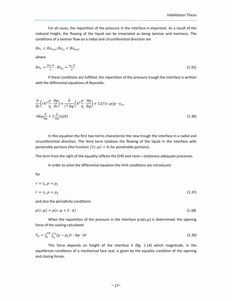
For all cases the repartition of the pressure in the interface is important As a result of the
reduced height the flowing of the liquid can be emaciated as being laminar and inertness The
conditions of a laminar flow on a radial and circumferential direction are
lm lt lm5o lmp lt lmp5
where
lm = HB∙ZH ∙ lmp = pB∙ZH (135)
If these conditions are fulfilled the repartition of the pressure trough the interface is written
with the differential equations of Reynolds
partpartr sLℎ 0ƞ ∙ partppartru + partL partφsℎ 0ƞ ∙ partppartφu + 12wL Q)0 ∙ 2Cx
=6(ωyyz+ 2 yyz)0ℎ) (136)
In this equation the first two terms characterize the new trough the interface in a radial and
circumferential direction The third term totalizes the flowing of the liquid in the interface with
penetrable portions (the function wL Q) = 0 for penetrable portions)
The term from the right of the equality reflects the EHD and nonemdashstationary adequate processes
In order to solve the differential equation the limit conditions are introduced
for
L = Lo 0 = 0
L = L 0 = 0 (137)
and also the periodicity conditions
0L Q) = 0L Q + 2 ∙ 6) (138)
When the repartition of the pressure in the interface p=p(rQ) is determined the opening
force of the sealing calculated
41 = f f 0 minus 0)L ∙ 7Q ∙ 7LUgh (139)
This force depends on height of the interface h (fig 114) which magnitude in the
equilibrium conditions of a mechanical face seal is given by the equality condition of the opening
and closing forces
Habilitation Thesis
4 = 4 + 4 where4 is the spring force and4 is the hydraulic force) Alter that the
leakageflow is calculated Q = |ƞf cLℎL Q)gh =gt=dx7Q (140)
and
i~ = 0 ∙ i (141)
Fig 114
The moments that oppose the rings angular deformations
ee = minusf f 0L PQQ7Q ∙ 7LUgh d (142)
The axial hydromechanics stiffness is
CC = minus yyk (143)
The angular stiffness is = minus yy (144)
where L M are the coordinates of the axes x and y
The axial and angular liquidation coefficients of the mobile rings
CC = minus yyk = minus yy (145)
where the point represents the derivation in relation with time
The power consumption of the annular radial couple is
() = ƞ ∙ K f f [ZG)7Q ∙ 7Lgh (146)
Habilitation Thesis
143 Conclusions
In face seals the contact points of the asperities on the two seal surfaces pressed against
one another with an avenge pressure p could distort both plastically and elastically Thus the most
highly stressed bearing points will be distorted plastically or worn away while the neighboring areas
will be elastically distorted In the usual combinations of materials for face seals 3 carbon graphite
ring is usually run against a metal metal oxide or carbide ring Their elastic modules are normally
much different Since the surfaces are always highly finished the low modules ring will always take a
considerably greater proportion of the distortion in the ratio
For this reason the sliding surfaces under load will look more like an aerial photograph of a
group of lakes then of a group of islands in the hollow spaces between the spaces are seldom
connected to one another With the rotation of one ring it is possible to imagine that the Liquid is
transported from one hollow to another as in the case of a revolving door until the liquid particle
emerge at the for site of the gap Thus in this range there will be no detectable influence of viscosity
As long as liquid inflow and outflow counterbalance each other no pressure builds up in the
interface
The following requirements for liquid exchange flow and the consequent leakage losses can
be summarized as follows no detectable viscosity influence no measurable gap pressure no seal
width effect a strong roughness influence an approximately quadratic sliding pressure influence
centrifugal force and outlet flow section effects a sliding speed effect
15 Model and analysis of a mechanical seal by finite element
method Interface tension distribution
151 Introduction
Modeling to access solutions [13] is the goal of predictive engineering The research presents
boundary element analysis or the numerical simulation of the behavior of a mechanical face seal
The present boundary element analysis is a particularly one for it contains the nonlinear effect due
to changes in boundary conditions resulting from the contact of the static ring and the sealing head
of the face seal These all have significant influence on the behavior of the system [88] The results
can be used for optimizing designs predicting limits or investigating failures
Fig 115
Habilitation Thesis
~ 30~
In a face seal (Fig 115) an axial force presses a rotating floating ring 5 against a fixed
counter face 6 The axial leakage path between the floating ring and the shaft is closed by a static
seal such as an O-ring 7 The static and sliding surfaces of the traditional stuffing box arc effectively
interchanged with the advantage that the geometry of the sliding scaling surfaces can now be
produced more accurately and less expansively and there is no longer any wear on the shaft-to-shaft
sleeve [85]
To compensate for any lack of alignment of the seal faces and for longitudinal thermal
expansion of machine and seal as well as wear of the seal faces the face seal must contain at least
one flexible member such as a diagram bellows elastomeric seal or spring 1 3 (Fig115)
However there are various causes for face seal leakage that place through the radial seal
gap formed by the two sliding surfaces [84] Leakage appears in most eases due to the distortions
causes by stresses Therefore it is of great importance to know the stress distribution along the
interface
152 Friction contact problems by boundary element analysis
When friction is considered the tangential displacement in the interface implies energy
dissipation The problem is solved by incremental computation Portions of the structure can have
areas of gaps that can change during a nonlinear analysis
The basic nonlinear solution approach involves a series of incremental solution is predicted
using the current state (stiffness and load increment) Depending on the type of nonlinearity a force
imbalance or residual is created during an iteration are required to balance equilibrium (correct)
for unbalanced forces [73] [76]
The iterations continue during an increment until the convergence criteria is satisfied Once
convergence is satisfied a solution is obtained for the increment and the solution progresses to the
next increment using this predictor-corrector method
An advancing schemes arc used to apply loading in a logical and controlled manner
Advancing schemes are used to apply loading in a logical and an efficient [48][49][36] numerically
stable solution
The most common advancing scheme is the application of loads or enforced displacements
in equal increments [77][78] The magnitude of the load or displacement increment is important
especially when small values of force or displacement cause a large change in response
153 Boundary integer formulation [18][19][11]
When friction is considered the dependence between normal tension and tangential ones is
defined by the friction coefficient The slide zone is divided in two parts corresponding with slide
state or an adhesion state = plusmn ∙ 7P) || lt ∙ ||O7ℎmP) (147)
Habilitation Thesis
The signe in (1) is choose so the energy is dissipated The friction coefficient depends on the
effective total sliding ve
Fig 116
2o) = ~ 1 minus V 9Y ∙ mZH (148) 2o = sum|2o| (149)
-where h is a consolidation coefficient When the initial friction coefficient j ~ -the limit friction
coefficient are equals the ideal relationship of Coulomb is vailable Therefore the friction coefficient
is continuously changing during the charge
The new values for the friction coefficient for each charge step The effect is that that an
element who is changing the state of contact from adhesion to sliding or from sliding to adhesion
changing the friction coefficient value presents a residual tangential force
(150)
If there is only sliding to sliding (Fig116)
(151)
The increment of the tangential force for sliding is
(152)
1 2 11( )n n n nt tε micro microminus minus minus∆ = plusmn minus
1 2 1 2n n n nt t tεmicro minus∆ = plusmn sdot∆ +
1 1 11 2
n n n nt t tε micro minus minus minus∆ = plusmn sdot minus
Habilitation Thesis
~ 32~
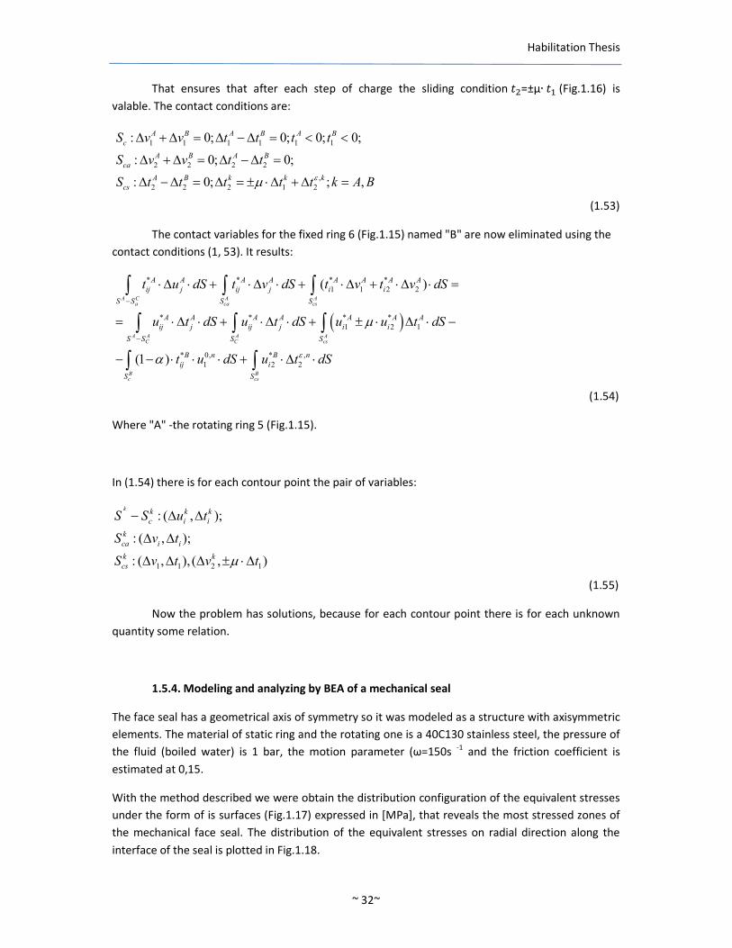
That ensures that after each step of charge the sliding condition =plusmnμ∙ (Fig116) is
valable The contact conditions are
(153)
The contact variables for the fixed ring 6 (Fig115) named B are now eliminated using the
contact conditions (1 53) It results
(154)
Where A -the rotating ring 5 (Fig115)
In (154) there is for each contour point the pair of variables
(155)
Now the problem has solutions because for each contour point there is for each unknown
quantity some relation
154 Modeling and analyzing by BEA of a mechanical seal
The face seal has a geometrical axis of symmetry so it was modeled as a structure with axisymmetric
elements The material of static ring and the rotating one is a 40C130 stainless steel the pressure of
the fluid (boiled water) is 1 bar the motion parameter (ω=150s -1 and the friction coefficient is
estimated at 015
With the method described we were obtain the distribution configuration of the equivalent stresses
under the form of is surfaces (Fig117) expressed in [MPa] that reveals the most stressed zones of
the mechanical face seal The distribution of the equivalent stresses on radial direction along the
interface of the seal is plotted in Fig118
1 1 1 1 1 1
2 2 2 2
2 2 2 1 2
0 0 0 0
0 0
0
A B A B A B
c
A B A B
ca
A B k k k
cs
S v v t t t t
S v v t t
S t t t t t k A Bεmicro
∆ + ∆ = ∆ minus ∆ = lt lt
∆ + ∆ = ∆ minus ∆ =
∆ minus ∆ = ∆ = plusmn sdot∆ + ∆ =
( )
1 1 2 2
1 2 1
0 1 2 2
( )
(1 )
A C A Aa ca cs
A A A AC C cs
B Bc cs
A A A A A A A A
ij j ij j i i
S S S S
A A A A A A A
ij j ij j i i
S S S S
B n B n
ij i
S S
t u dS t v dS t v t v dS
u t dS u t dS u u t dS
t u dS u t dSε
micro
α
minus
minus
sdot∆ sdot + sdot∆ sdot + sdot∆ + sdot∆ sdot =
= sdot ∆ sdot + sdot∆ sdot + plusmn sdot ∆ sdot minus
minus minus sdot sdot sdot + sdot∆ sdot
int int int
int int int
int int
1 1 2 1
( )
( )
( ) ( )
k k k k
c i i
k
ca i i
k k
cs
S S u t
S v t
S v t v tmicro
minus ∆ ∆
∆ ∆
∆ ∆ ∆ plusmn sdot ∆
Habilitation Thesis
The configuration of those quantities is an expected one with a maximum to the inner radius of the
mechanical seal
Fig 117 Fig118
The nonlinear analysis makes creating and setting up the proper nonlinear solution strategy
16 Interface contact pressure distribution in dynamic contact face
seals Analyzed by FEM
161 Introduction
A great diversity of Contact seal designs materials operating conditions and factors that
affect their performance have not yet allowed the general conclusions on friction and wear of this
seals to be drawn At the same time the results of studies of particular cases may often lead the
design engineer to an erroneous decision if the seal develops it different in some way from that he
has taken as a prototype In some instances these factors are interdependent [67] The study
presents the service conditions of sliding contact seals in machinery determined by combinations of
the above factors analyzed by FEM (finite element method)
The performance of seals is characterized by the degree of tightness service life power
losses by the extent of damage to the contacting surfaces in operation etc the degree of tightness
wear life ta and performance factor are the most important characteristics of seal performance In
addition to the above factors temperature whose level is determined by their joint action also
effects the performance of dynamic seals [80] The service conditions of sliding contact seals in
machinery determined by combinations of the above factors are very diverse The temperature
pressure flow rate and properties of the fluid are chosen depending on the seal application
Dynamic contact seals such as face (axial) seals operate with external continuous friction
Habilitation Thesis
162 Friction and wear in dynamic contact seals
A great diversity of contact-seal designs materials operating conditions and factors that
affect their performance have not yet allowed the general conclusions on friction and wear of these
seals to be drawn At the same time the results of studies of particular cases may often lead the
design engineer to an erroneous decision if the seal he develops is different in some way from that
he has taken as a prototype [20][21][22][23]
For the face seals design calculation methods have been devised for the assessment of fluid
pressure (with regard to out-of-squareness of the faces and to pressure in the clearance) behavior
of the fluid sealed in face clearances hydrodynamic effect for the sealing rings deformations of the
rings due to pressure and temperature and also temperature fields in the rings of the rubbing pair
163 Design and operation of a mechanic face seal
In a face seal an axial force presses a rotating floating ring against a fixed counterface or vice
versa The axial leakage path between the floating ring and the shaft is closed by a static seal such as
an O-ring elastomeric sleeve or U-seal etc Figure 119 shows a simple form of face seal The static
and sliding sealing surfaces of the traditional stuffing box are effectively interchanged with the
advantage that the geometry of the sliding sealing surfaces can now be produced more accurately
and less expensively and there is no longer any wear on the shaft or shaft sleeve To compensate for
any lack of alignment of the seal faces and for longitudinal thermal expansion of machine and seal
as well as wear of the seal faces the faces seal must contain at least one flexible member such as a
diaphragm bellows elastomeric seal or spring Figure 120 shows a very simple design for a face
seal
Figure 119 Loaded face seal
(1)floating ringhousing (2) seal (3)
compression spring (4) driving ring
(5) counter ring (6) O-ring (7) anti-
torque drive pin
Figure 120 Simple face seal design
(a) before fitting (b) in working
position (1) Synthetic resinring (2)
rubber tube (3) impeller of pump
(4) pump housing
Habilitation Thesis
164 TribologyFriction regime of a mechanical seal
In a face seal there are together the functions of a bearing and of a heat exchanger In order
to have an acceptable endurance the face seals must ensure a complete fluid film of lubricant so
even if one can talk about a seal its functional characteristics are the same as of a plane friction fluid
joint the opening axial force the film stiffness leakage and friction torque The tribologic behavior of
a sliding friction joint is described by the Stribeck relation between the friction coefficient μ and the
Gϋmbelcriteria(Gϋ=ƞpgt = G )(Fig 121)
Fig 121
The local contact zone stresses of the face seal appear from the external loading and from
the sliding speed To a precise load (Fm) the contact pressures distribution (pmax ) and its average value
as well as the friction torque depend on friction joints geometry So the friction forces repartition
on different zones of the friction joint is not uniform The external friction forces are function the
stresses condition from the real contact zone It is necessary to achieve the equilibrium relation
45hiexclcentTpound) = f 0 lowast 7hN (156)
that implies that the fluid film pressure distribution is known
The theory must to consider the sealed fluid properties the materials of the two rings of
the seal by their mechanical and thermal properties the friction joint geometry
The model of a lace seal must to take into account the interface phenomenon together with
the heat transfer between the seal rings so the mathematical model consists on the Reynoldsrsquos
equation the interface geometry the energetic fluid equation the temperature dependence of the
fluid viscosity the temperature dependence of the fluid density the interface limit condition
filmwall the Fourier equation the rings thermal limit conditions the thermal resilience equations
and the supporting conditions of the face seal rings In all it is very important that the interface
pressure distribution is known The fluid flow can be considered as laminar and without inertia
because the fluid film is very thin
Gϋ=G
Gϋ=ƞpgt
Habilitation Thesis
165 The friction forces the friction torque and heat in the sliding friction joint of
a face seal
At a given force (4) the contact pressure distribution and the friction coefficients depend
on the friction jointrsquos geometryBetween two plane rigid surfaces with an incident angle αyen 0and
the Oz breadth infinite ( h = x∙ tanuml cong α∙ x 2C = 0) (Fig 122) the pressure distribution[90] is
Fig 122
0lowast=6ηvf ZZZ[Uk 7 = bordflaquo∙V notk∙]YФh cupФh = macr)∙macr~)~macr) (157)
4deg = f0lowast7plusmn = bordflaquoV notk∙]YФgt cup Фgt = sup2 Vℎ~~ minus ~Y (158) where
plusmn~ minus the coordinare where the sections average pressure and the height of the lubricant film is
ℎ~ = minus22 2 cong O ∙ plusmn~
for x=plusmnhthe minimum thickness of the fluid film is
ℎh =α∙ plusmnh = uml ∙ sup2 ∙ umlOP7sup3 = ∙k m=k (159)
The friction torque at the interface will be
e) = 260~lowast f L7L = 6l minus L) ∙ 0~lowast = ∙ 4 ∙ L~ cup L~ = acute[[acute (160)
Together with the Newton and Reynolds equations the friction force coefficient are
τ=η1H1 rarr 4)Upara = f middotcedilℎ) cedil0) sup1h 72 = fR2 V_Z minus 3 ZZ Y 7P (161)
Habilitation Thesis
~ 37~
μ=raquofrac14UpararaquoUpara = Zk Ф cupФ = s ~+ ~~ + ФUfrac12u (162)
From the friction power expression
() = ∙ 4 ∙ 2 (163)
The factor (0~lowast 2~) can be global criteria for the heat control of the friction jointrsquos rings
(0~lowast 2~) =raquo]frac34∙pgiquest1) le 0~lowast 2~) (164)
WhereK minus rotation speed
2~ = K ∙ L~ cup L~ = _(D+7h)
The fluid friction regime where the friction coefficient is minimum (Fig 121) appears at the
rotation speed (K) at a limit value of the Sommerfeld invariant (Aacuteh)
[Aacuteh]=gtAcirc`cpd cup 0~lowast rarr cKd = gtAcirc`ckd c2d = cKdL ∙ 10
[μ]cong3`cpdgtlowast ) 8 cup 0~lowast (166)
At the boundary friction domain the friction coefficient is
μ=AtildeAuml9cpdp)cpdpAuml9)cpdp cong μ-j~ minus pcpd cd minus μ-j~) (167)
From the thermal equilibrium equation results the regime temperature of a boundary
friction face seal
() = ∙ 4 ∙ 2 = AElig ∙ +Ccedil ∙ ∆) = h + Eacutefrac14BEcirc∙EumlIgrave le ~ (168)
where
k- Thermal coefficient +Ccedil minusthe free surface (heat exchanger) of the seal
The friction regime and the thermal equilibrium are independent So the effective friction
coefficient () and the regime temperature of the sliding friction joint ()) are established by
iterations function the temperature lubricantrsquos viscosity variation
166 Conclusions
The functionalperformance parameters of a mechanical face seal depend on the interface
pression and temperature distribution Therefore it is very important to know them and the FEM
analysis allows the tension distribution the displacements and the temperature determination All
the other parameters can be then determined
(165)
Habilitation Thesis
~ 38~
17 Automotive Mechanical Face Seals ndash Tribological
Simulation
171 Aims and background
The behavior of a face seal is determined by the complex interaction of a number of factors
Advantages are usually attained at the price of disadvantages in other directions For example if the
roughness is constant an increase of the contact pressure reduces leakage[89] but the wear and
frictional heat increase As against this increasing leakage losses can reduce the friction and heat
production but the effectiveness of the unit as a seal is reduced Again a high friction may not only
lead to increased wear but also due to thermal distortion to considerable leakage losses or it may
cause the seal to break down because of a thermal stress cracks
By appropriate seal design choice of materials and type of seal arrangement individual
requirements such as minimum leakage maximum life or minimum friction can be met The
research presents the finite element method (FEM) and experimental analysis of the leakage and
friction rates of a mechanical face seal for the chemical industry The behaviour of a mechanical face
seal in run can be simulated and illustrated on the computer
For any of the type dimensions taken into consideration the basic structure consists of
primary sealing formed of
bull the pressure ringfloating ring elastic andor in movement of rotation
bull the fixed counter face friction ring
The ensemble of the sealing shows axial symmetry both from the point ofview of geometry
and mechanical loading[54]Structurally speaking the pressure ring assembled in elastic way has 5
degrees of freedom and some forces act upon it hydrodynamic force elastic force the force of the
pressure in the clearance the centrifugal force and so on
The simulation on the computer is based upon a solution of the equations of motion of the
element assembled in elastic way associated with the interaction of the two rings due to the surface
contact with friction[24][5][27]
The analysis through FEM allows the detection of instabilities and the determination of the
functional parameters of the mechanical face seal[25][26]
The most important parameter from the point of view of the performance is the leakage
flow-rate Q proportional with h3 (the size of the clearance)[28][29]
Maintaining a pre-estabilished distance between the active surfaces of the rings of the
primary seal which is dependent on the kinematics of the pressure ring[55][83] the force and
moment system to which some forces are opposed forces like hydrostatic (HS) hydrodynamic (HD)
thermo-hydrodynamic (THD) or elastohydrodynamic (EHD) and mechanical through the surface
contact with friction are the key factor in their design[81]
Habilitation Thesis
used for representing volumes of revolution The axisymmetrical elements may be defined in the
plane xy or xz of the global coordinates system and the postprocessing is done for the whole volume
of the structure
For the study of the structure in this case the study of a section that contains the body axis
of revolution is enough and the representation is done in the axis system x y (Fig 124) For such an
element the knots become nodal circles with the center on the axis of revolution
Fig 124 Ring with constant transversal section
The transversal section of the ring-shaped element is defined in a certain transversal section
which contains the axis of revolution Due to symmetry shifts on circular-lined direction are not
produced The shift vector has thus only components on radial direction u and axial direction vAs a
result the degrees of freedom attached to the element are the knotted values of these shifts
The approximation functions express thus the variation of these components on the element
domain
(169)
Where δ is the vector of knotted shifts
If natural coordinates s t are used the relation becomes
( )( )
sdot
=
n
n
n
n
v
u
v
u
NNN
NNN
tsv
tsuM
K
K1
1
21
21
000
000
where n=4 in the case of four-sided three-dimensional elements
The natural coordinates are normalised coordinates obtained by rating theglobal
coordinates of the entire domain of digitisation to characteristic measures of the finite element
The axisymmetrical problem differs from the state of plane deformation from the point of
view that the normal specific deformation on the plane of work section ε0 is not equal to zero and
must be developed in the vector of the specific deformations ε
Its value is expressed in the following form
( )( )
[ ] δsdot=
Nyrv
yru
(170)
Habilitation Thesis
~ 41~
r
u=θε (171)
The relation between the specific deformations and shifts has the form
sdot
=
u
y
v
r
v
y
u
r
u
rry
y
r
partpartpartpartpartpartpartpart
γεεε
θ
00110
10000
01000
00001
The connection between the tensions and specific deformations is
( ) ( )
sdot
sdotminusminus
minus
minus
sdotsdotminussdot+
=
ry
y
r
ry
y
r
E
γεεε
νννν
νννννν
νντσσσ
θθ
2
21000
01
01
01
211
where E is the longitudinal coefficient of elasticity v ndash coefficient of Poisson
If [J] is the Jacobean matrix of conversion and [ J ] is its reverse then the derivativesof shifts u v in
relation with global system r y has the following form
sdot
=
u
t
v
s
v
t
u
s
u
JJ
JJ
JJ
JJ
u
y
v
r
v
y
u
r
u
partpartpartpartpartpartpartpart
partpartpartpartpartpartpartpart
10000
000
000
000
000
2221
2211
2221
1211
where the derivatives vector in relation with the natural system st is calculated with relationship (170)
sdot
=
n
n
n
n
n
n
n
v
u
v
u
NNN
t
N
t
N
t
N
s
N
s
N
s
N
t
N
t
N
t
N
s
N
s
N
s
N
u
t
v
s
v
t
u
s
u
M
K
K
K
K
K
1
1
21
21
21
21
21
000
000
000
000
000
partpart
partpart
partpart
partpart
partpart
partpart
partpart
partpart
partpart
partpart
partpart
partpart
partpartpartpartpartpartpartpart
(172)
(173)
(174)
(175)
Habilitation Thesis
~ 42~
Relation (175) has a general form which is valuable both for the linear finites elements and
for those of superior orderIn the particular case of mechanical face seal model n=4 the element
has four knots in r y plane
Relations (172) (174) and (175) allow the matrix [B(st)] calculus in the relation
ε=[B]δ
We notice that matrix [B] contains only four lines in comparison with the plane problem with
only three The matrix of elasticity is at its turn of 4times4 given by relation (173)For the calculus of the
matrix of stiffness the numeric integration of the expression is also used
[ ] [ ] [ ] [ ]int sdotsdotsdot=V
TVdBEBk (176)
The axisymmetrical finite element model of the mechanical face seals The knowledge of
induced stress configuration of the entire structure is necessary so that we could run some
modifications of its configuration in order to satisfy better the conditions imposed by the
solicitation material reliability etc
The basic problem of modelling having as destination the stress analysis requests the
determination of the induced stress in areas where their gradient is high
The calculus models which use the displacement method ndash in this category the method
of the finite element is also includedndash uses as basic entity the structure matrix of stiffness the
primary unknowns of the model being the knots shifts of the digitisation array the tensions are the
secondary unknowns So for these kinds of models a stiffness analysis of the structure is made
Geometrically speaking the mechanical face seals presents rotational symmetry for it is
made from revolution bodies (Fig 125)
The study presents two types of chemistry mechanical face seals analysed by FEM that run at p =
01 MPa n = 3000 revmin with fluid at 80degC
Figure 125 Finite elements digitization of the primary seal of a mechanical face seal
Materials combination for primary sealing rings of the mechanical face seal is also known (Table 12)
Habilitation Thesis
~ 43~
Tab 12 Materials combination for primary sealing rings of the mechanical face seal
Carbo-graphitic material Cod
Carbo-graphitic materials binded with resin
B1
Rough coal impregnated with resin
B14
Rough coal impregnated with antimony
B17
Plastics
PTFE + 20 Fiberglass Y1
PTFE + 25 Graphite powder Y2
Metalic material
Ion-nitrate stainless steel G1
Stainless steel (40C130) G10
Metallic carbide
Wolfram Carbide U1
Silicium carbide U2
Ceramics
Al O - 89 V1
Basalt V2
The models analysis repeats for each two constructive types made by different materials
pairs The contact is described by a new type of lsquoslide linersquo elements which includes the
stiffnessfriction dates the scale factor and the friction coefficient between the contact surfaces
The analysis results are shown on sections (Fig 126) and the analysis program system is
presented in figure 127
The post-processing concerns geometric digitisation and analysis results in order to control
the analysis validation
bull the check up of correct application of the piece real dimensions of total volume and of total
mass
bull the check up of correct application of loads and of used physical and mechanical proprieties
(taking the parts into account the heterogeneous character of the assembly)
bull intensity control of deformations and stress (deformations smaller than 0002 for the steel for
example)
bull the check up of global equilibrium conditions using the loads and the calculates reactions
bull the check up of the conformity of the main tensions value with the geometric assembly
orientation
bull the displacement amplitude in ratio with the parts dimensions according to the geometrical
linearity
2 3
Habilitation Thesis
~ 45~
processing we obtain also the interface contact pressure distribution the displacements and the
thermal loads of the rings (Fig 127)
Fig 128 The contact pressure distribution along the interface of a face seal by FEM
174 Leakage flow-rate evaluation
In unisothermal flow case of a incompressible fluid for an axial symmetry configurationthe
Reynolds equation has the following form[31]
03
=
dr
dph
dr
d
η (177)
where η is dynamic viscosity of work fluid
Keeping in mind the following
bull in the limit below of the mentioned case the float rate of leakage in the
clearance is given by
b
phdQ m
ηπ
12
3∆= (178)
where dm=05(d+D) b=05(Dndashd) h=05(Rz1+Rz2)
-1914
-1805
-1696
-1587
-1478
-1369
-1260
-1151
-1042
-0933
-0824
-0715
-0606
-0497
-0388
-0279
-0170
-0061
0048
0235 0750 1266 1781 2250 2719
pc
[MP
a]
h [mm]
O1 V7221 G10Y2
O2 V7221 G10B1
Habilitation Thesis
~ 47~
( )
sdot+sdot
∆sdot= pv
k
p
b
hAQ
Tf
T microη
112 2
3
(183)
The flow losses variation through outflow to a frontal tightening are presented in figure 129 175 Conclusion
FEM analysis has taken into consideration the two physic aspects with fundamental influences on mechanical face seals function like thermal and mechanical From mechanical point of view the safe function of mechanical face seals involves the existence of stable cover of fluid in the clearance couple It must carry the contact pressure created on the interface through the elastic elements and also the pressure of the tightening fluid The stable functioning can be perturbed when the thermal and mechanical displacement of the assembly are combined with the nonlinearity induced through an unfit assemblage From the analysis of the friction contact surfaces results that bull the film thickness is of a micrometer size order of the same size as the geometrical precision of the plane combined with the form and position deviations which is also dependent on the relative position (nonalignment) of the activsurfaces of the primary sealing rings bull the transversal sections of the sealing surface must be as uniform as possible in order to prevent distortions bull the contact pressure in the clearance shows an allure that confirms the theory of the hydrodynamic lubrication bull the variation of the contact pressure with friction in the clearance on radial direction is quasi-identical for all the pairs of analysed materials with some exception (the antifriction superior properties of PTFE (Y2)) bull the maximum value of the contact pressure for any of the analysed alternatives is bigger than the pressure of the sealed fluid which ensures the fulfill of the sealing function bull by knowing the real distribution of the calculated pressures in the clearance one can evaluate with precision the most disadvantageous level of the flow rate bull the axial displacements of the pressure ring resulted through calculus are of the same sense with those of the friction ring overcoming them with values that do not lead to the installation of dry friction (at limit ndash adherence) but keeping the sealing function bull the axial displacements of the two rings of the primary sealing with values between (0012 01) μm are situated below the level of the measure of the microgeometric active surfaces having an insensible influence over the clearance measure bull for materials couple PTFEPTFE (Y2Y2) the level of axial displacements overcomes the microgeometric measure of the active surfaces not being recommended to be used NOMENCLATURE h ndash the size of the clearance kT ndash heat transfer factor n ndash rotational speed p ndash sealed fluid pressure r ndash radius s t ndash natural coordinates u ndash radial direction shift vector v ndash axial direction shift vector x y z ndash global coordinates E ndash longitudinal coefficient of elasticity Q ndash leakage flow-rate
ω ndash angular speed ε0 ndash normal specific deformation on plane of works section η ndash dynamic viscosity of working fluid ν ndash coefficient of Poisson σ ndash tension δ ndash vector of knotted shifts [J] ndash the Jacobian matrix
Habilitation Thesis
~ 48~
18 Calculation by Finite Element Method (FEM) of
Temperature Distribution in the Components of a
Mechanical Face Seal
181 Aims and background
The temperature in the seal interface due to frictional heat has a considerable influence on
the behavior of a face seal affecting wear and thermal distortion If the temperature is too high
vaporization of the lubricant film occurs causing increased friction and wear [1][82] The safe
working temperature of the face materials can also be exceeded and the seal will then fail due to
welding or thermal stress cracks The friction heat produced in the seal interface can be removed by
conduction convection and radiation processes The heat produced in the seal interface is
transported away by conduction in the seal rings and from the seal rings it is passed on to
surrounding fluids by convection Some also is lost to the surroundings by radiationThe maximum
temperature in the interface is of particular interest[66]
Face seals are used over a temperature range from -200ordmC to + 1000ordmC The proprieties of
many materials are only known at room temperatures so that exact calculation of the maximum
permissible temperature difference and thermal resistance factors at the working temperatures is
not possible[87]
182 Fundamentals
Different temperatures and their gradients influence the geometry of the seal gap In the
case of elastic distortion the magnitude of the elastic modules and the dimensions of the rings are
the determining factors and in thermal distortions it is the values of the thermal properties of the
materials[62] such as thermal conductivity λ thermal expansion coefficient α and heat factors in
conjunction with the construction of the rings which influence the temperature gradients and in
turn the gap shape[29]
The temperature gradient in both axial and radial directions influences the geometry of the
seal gap
A Axial temperature gradients
The axial temperature gradient leads to distortion of the sealing rings Newman and
Forray[5] derived formula for the thermal distortion of the face of a ring elastically clamped on the
internal orexternal diameter With the notation of figure 130 (where d ndash inner diameter of the ring
D ndash external diameter of the ring) and assuming that there is a linear axial temperature gradient
Habilitation Thesis
SIacute = IcircIumlETHIumlNtildeOgraveIcircOacute (184)
Where
C = T minus TOumll
and CF is a shape factor
With face seals the heat loss is mainly at d or D In the case of distortion due to the
influence of the axial temperature gradient heat loss at D has the effect of producing a negative
distortion STr ie contact results at d If the heat loss is at d then the outermost regions of the ring
are hotter and contact occurs at D making STr positive1
B Radial temperature gradients
In mechanical seals there are often several heat sources which strongly influence the radial
temperature distribution in the rings
In addition to the friction heat from the sliding interface the medium to be sealed may be a
source of heat as well as a hot shaft or housing and heat from liquid turbulenceDepending on the
direction of the temperature gradient (the heat loss can be at d or D) the temperature distribution in
the sealing rings can differ considerably Those areas of the rings which lie furthest from the heat
sink or are nearest to the source of heat show the highest temperatures They expand to a greater
extent than other sectional areas and alter the shape of the original parallel film gap Assuming a
constant source of heat and constant operating conditions with a linear temperature gradient in
axial direction we have
Fig 130 Thermal distortion due to axial temperature gradients (a) light clamping on the external edge (b) light clamping on the internal edge
Habilitation Thesis
~ 50~
C = IacuteIacutetimesOslash in ordmCmm (185) e = r minus rcent for the axial ring distortion and the approximate formula SIacute = albC (186)
results where α is the thermal expansion coefficient for temperature range (T+TA)2 and l the axial
length of the ring which is expanding The radial temperature gradient Cr depends upon the heat
source the thermal conductivity and the heat transfer coefficient which in turn is influenced by the
liquid the viscosity and the speed Exact values for constant operating conditions can only be
established by tests If the heat sink lies at D then STa becomes negative and the contact of the rings
is at the internal periphery For a heat reduction at d STa is positive and contact takes place near the
external periphery [5]
C Temperature gradients
The axial and radial temperature gradient distributions in mechanical seals can differ
considerably Above all the seal design construction of materials location of heat sink quantity of
heat to be dissipated the heat transfer coefficients and the cooling method all have a considerable
influence Exact values can only be attained by measurement under operating conditions
Qualitatively however it can be said that a low conductivity is associated with a large temperature
gradient and high face temperature and vice versa Furthermore for the same conductivity the
temperature gradient in the rotating ring is higher than in the stationary ring if both rings are in
contact with the coolant Also the better the heat transfer coefficient from ring to medium the
higher the temperature gradient in the ring [5]
D The heat transfer coefficient
Seal rings have to be at a higher temperature than the sealed medium (coolant) in order for
heat to be transferred from ring to medium In most face seals the frictional heat flows axially in the
ring since the heat sinks are normally at d and D If equal areas are assumed and the seal width b is
taken for the heat flow path length and a constant coolant temperature t is assumed UacuteUcircIcircUuml = YacuteIacuteTHORN)szlig (187)
where
P ndash net closing force per unit area of interface
f ndash friction coefficient
V ndash relative sliding speed of interface
C4 ndash conversion factor depending on units used
t ndash temperature of sealant or coolant
In fact however the heat transfer process is considerably more complicated The heating
effect can be limited or increased by the design and layout of the rings the insulating effect of
elastomeric mountings and static seals compression seating and surface coatings and by
Habilitation Thesis
~ 51~
indentations in the seal surfaces or ring parts The transfer from seal ring to coolant involves various
temperature differentials The heat transfer coefficient is a function of the Reynolds Number Re
laminar flow assists the heat transfer process Viscosity flow rate and entry turbulence of the
coolant in the seal space or additional agitation of the coolant liquid open springs and indentations
of the seal also have a strong influence on the heat transfer If all these factors are combined in one
dimensionless heat dissipation factor Cw for a constant operating condition and one type of seal
then the temperature T in the seal gap is
T = UacuteUcircszligIcircagraveIcircUumlYacute+ t(188)
Depending upon the nature of the coolant and the operating conditions the values of Cw lie
in the range 02 ndash 09 the actual temperatures in the seal gap can be considerably greater than
those calculated by equation (187) Thus the heat dissipation factor Cw can be defined as the
relationship of the seal interface temperature to the actual temperature Tw
Caacute = IacuteacircIacuteagrave (189)
The temperature dependence of thermal conductivity λ must also be considered in equation
(188) A linear variation of the temperature coefficient β for the temperature range in question can
be assumed and the average value set at
λ = YacuteaumlYacuteaumlU (190)
E Heat crazing
One of the greatest dangers in mechanical seals is the formation of thermal stress cracks on
the sliding faces These can be caused by a momentary overload due to dry running as a result of
failure of the coolant or by a large load or speed variation The cracks lead to increased wear and
with balance of seals can cause the seal face to part
Thermal stress cracks can be largely avoided if the physical and mechanical properties of the
face and the operating conditions are considered carefully enough when the seal is designed
A surface cracks when differential thermal expansion causes the surface stress to exceed the
material strength Using Hookersquos law [27]
Eε = σ minus νσ(191)
and the thermal expansion equation
ε = ∆Tα(192)
Kingery calculated the greatest permissible temperature difference ΔT which the material
can just bear without being damaged by thermal stress[27]
ΔT = ecirceumligrave)IcircUiacute (193)
Habilitation Thesis
~ 52~
where
ν ndash Poissonrsquos ratio
E ndash elastic modulus
σZ ndash tensile strength
The form factor C1 takes into account the shape of the ring The calculation of the highest
permissible temperature difference ∆T in the surface depends on the thermal conductivity of the
material The greater the thermal conductivity the smaller is the results breakdown Many years of
practical experience and test results confirm that to assess the resistance of an individual material to
heat crazing a factor B = ∆Tλ can be used This is the thermal stress resistance factor
The values of the maximum permissible temperature difference are not by themselves
sufficient to determine the thermal stress effect and the resistance factor B1 is therefore
introduced
Carbon and graphite in particular are notable and with good dry running characteristics
high chemical stability and great stiffness are particularly suitable as seal materials1
183 Axial symmetrical modeling of heat transfer in primary seal of a mechanical face seal
Equation expressing mathematically a body temperature field is
Θ = fx y z t)(194)
and the temperature gradient
gradΘ = nh yotildeyT (195)
If q represents the unitary thermal flux the Fourier law expression becomes
q = minusλ yotildeyT = minusλ ∙ gradΘ(196)
The heat conductivity coefficient λ is a material constant and varies with the temperature
linearly in most cases The temperature variation in space and time in a body interior or a field is
expressed by the differential equation of conduction (Fourier) [191 192]
yyTHORN γct) = yyoslash Vλoslash yotildeyoslashY + yyugrave Vλugrave yotildeyugraveY + yyuacute Vλuacute yotildeyuacuteY + M(197)
where
Θ ndash temperature
t ndash time
c ndash specific heat
Habilitation Thesis
~ 53~
γ ndash specific weight
λxyz ndash coefficients of thermal conductivity after xyz directions
M - the flow of internal heat sources
In the variational approach of the method the integration of the equation (187) in time and
space limit conditions is equivalent to minimizing
J = f uuml λoslash VyotildeyoslashY + λugrave VyotildeyugraveY + λuacute VyotildeyuacuteY minus VM minus cγ yotildeyTHORNY Θyacute dV minus f qΘdS + f αΘVΘ minus ΘiacuteY dSUcirc (198)
where
α ndash heat transfer coefficient by convection from surface S to the surrounding environment or
reverse
ΘE ndash exterior environment temperature
The problem can be treated as an bidimensional case if the structurersquos geometrical form
and thermal load shows axial symmetry In the seal form Fig130the temperature varies only by x
and y axes and the finite element is a tor with quadrilateral section In equation (195) radius x is
variable on finite elementrsquos surface as so for the toroidal finite element the expression becomes [6]
J = 2πr 12 ^λoslash spartΘpartxu + λugrave spartΘpartyua dV minus MΘOslashdV minus qΘOslashdS + αΘOslash s12ΘOslash minus ΘiacuteudS[OslashOslashUcircUcirc
(199)
Minimizing J results
2πr cBdIacutecDdcBddVUcirc + cNdIacutecNddSUOslash ΘOslash minus McNdIacutedVUcirc minus qcNdIacutedS minus αΘiacutecNdIacutedS[OslashOslash = 0
(1100)
If we consider the radius in the center of gravity of the finite element the differential
element of volume will be dV = 2πrdA[27][29][30] For the finite elements with heat exchange by
thermal flux on the contour the differential element of surface is dS = 2πrprimedl where r = oslashoslashNtilde) is
the radius measured at the half side which has heat exchange by thermal flux
For finite elements with heat exchange by convection dS = 2πrprimeprimedl where r = oslashNtildeoslash) is
the radius measured at the half side which has heat exchange by convectionAssuming in this case
too that M is constant on the surface of the finite element and that q α ΘE are constant on the
finite elementrsquos side with heat exchange on the contour the equation (1100) becomes
Habilitation Thesis
~ 54~
V2πr f cBdIacutecDdcBddAOuml + αrprimeprimef cNdIacutecNddlS[Oslash Y ΘOslash minus 2πrMf McNdIacutedAOuml minus 2πrprimeq f cNdIacutedl minusSOslash2πrprimeprimeαΘiacute f cNdIacutedlSUOslash = 0 (1101)
Fig131 Meshing in axisymmetric elements of the EFS103 ndash S mechanical face seal
Fig 132 Isotherms distribution in primary seal rings of the EFS103 ndash S mechanical face seal for
sealed environment of water with detergentat 80ᵒC
The analysis of the thermal state with FEM [2] of the sealing rings depends on the
temperature of the sealing zone and the heat produced by the interface between the rings due to
relative motion with friction (n=3000 rotmin) 27][29][30] The mechanical face seals present
rotational symmetry for it is made from revolution bodies (Fig 131) The results of the calculations
with FEM are given in figure132
184 Conclusions
Instabilities of any nature are the main causes for removal from use of the mechanical face
sealsEffects of temperature distribution are the key elements in the study of mechanical face sealrsquos
instabilities
As a result it is important to have a detailed knowledge about the thermal state of the
primary seal rings
Habilitation Thesis
2 Constructive and functional analysis of machine parts used in
road vehicles
21 Rectangular section circlips retaining rings axial load -
carrying capacity considerations
211 Introduction Fundamentals
The axial load-carrying capacity of the circlips retaining rings analyses wasnt found by the
authors in literature Some technical design necessities such as small axial dimensions in industrial
robots pretension devices constructions lead the authors to take into account the research by means
of FEM (finite element method) of this aspect The conclusions of the study can be directly applied in
technical design and in the future if experimental research results are added the reconsideration of
the present standards regarding shape dimensions and materials can be made [91]
Circlips retaining rings are designed to position and secure component in bores and houses
simultaneously provide rigid end - play take - up in the assembly to compensate for manufacturing
tolerances or wear in the retained parts
The fundamental shaping of the circlip is of curved bars of same firmness The ring must
possess an exactly determined eccentricity z so that it deforms approximately under tension
Following the computation method for the dimensioning of the rings is to be pointed out in this
section It concerns particularly the determination of the relations of the bending stress whether
the radial width b and the deformation D -- d3 (fig 21)
Fig 21
For the technical designer who uses standardized andor in a list manufactured rings on shafts
or in housings with nominal diameter a computation is not necessary It is of crucial importance
however with special applications of the normal rings and particularly with the construction of
special rings The main requirement of the technical designer to the circlip is the transmission of
greatest possible axial forces of the machine part which can be specified on the groove of the shaft
or the housing The circlip must exhibit as large a thickness as possible s and width b and the groove
a large depth t for the fulfillment of this demand (fig 21)
Since the ring with pre-loading must sit in the groove d2 The diameter d3 of the ring is smaller
in the relaxed condition than the g become groove diameter d2 For the assembly the inside
diameter of the ring d3 must be become so far increased be pushed to it over the shaft with
diameter D can The deformation of the ring should be as far as possible flexible thereby The
Habilitation Thesis
bending stress resulting from the diameter change off is to be computed To the circular
deformation of a straight bar with the cross-sectional height b on a neutral radius of curvature r the
well-known relationship applies
EI
M
r
1 b= (21)
where
= 13∙ for 13 = and for 2 ∙ L = (22)
= ∙iquest
If a bar with a neutral radius of curvature r already curved is deformed on a radius p the
equation isEI
M1
r
1 bplusmn=ρ
minus (23)
Using the names for the neutral diameters usual with circlips
L = ∙ ρ= ∙ iquest[ minus iquestU = plusmn| (24)
The further derivative takes place left for the shaft rings and right for the housing rings Figure
22 shows circlips for shafts and housings with the main dimensions
Fig 22
iquest[ minus iquestU = minus| (25)
where = 13∙ 13 =
bEDDbEDD
bb
sdotminus=minus
sdotminus=minus
σσ
1331
1111 (26)
( ) ( )31
13
31
31
DD
bEDD
DD
bEDDbb sdot
sdotsdotminus=
sdot
sdotsdotminus= σσ (27)
Habilitation Thesis
~ 57~
The size of the neutral diameter depends on the eccentricity z Their correct choice is a
condition for the application of the formulas It is not possible to indicate for all kinds of ring and
large fixed value for z As average value can be set however
= 7 + + ∙C = 7 minus minus ∙C
= 7 + 075 ∙ = 7 minus 070 ∙
= 7 + 075 ∙ = 7 minus 070 ∙ ( )
( )( )( )
( )( )bdbd
bEdd
bdbd
bEddbb sdotminussdotminus
sdotsdotminus=
sdot+sdot+
sdotsdotminus=
700700750750 31
13
31
31 σσ
(28)
Before one dissolves the equations 28 at given values of D and d3 for the computation the
width after b it is simpler to estimate the width first and calculate the tension After the first result a
correction is according to the relation
asymp 7 minus 7) ∙
The then still existing deviations from the circle are seized in the equation 29 by the factor
115 The neutral diameters D and D3 amount to with circlips D=D plusmn b andor d3 plusmn b it results
then
( )
( )( )( )
( )( )bdbd
bEdd
bdbd
bEddbb minusminus
sdotsdotminus=
++
sdotsdotminus=
31
13
31
31 151151σσ (29)
For the dimensioning of special pliers and for special applications of circlips it is often
important in particular to know the forces which are necessary for the flexible deformation This
applies particularly with the utilization of the favorable featherspring characteristics of the circlips
firmness same as curved bars with the employment as foreign suspensions in electrical contacts
= 13 = Eacute∙|∙b∙N
Becomes
P=∙∙Nb∙|
(210)
The bending stress is computed after the equations 28 or 29 If it lies over the yield strength
of the material then only this may be used
The crucial question with the application of the circlips is those the axial load-carrying capacity
It cannot be answered by denomination of a number The maximum stress of the circlip connection
depends on different always dunging factors
The most important are the firmness of the work material into which the groove is in-stung
the groove surface and the form of the pressing in slightly machine part (sharp edged rounded
selvedge distance chamfers) There is thus computation methods necessarily which consider these
changing factor
Habilitation Thesis
212 Computation of the circlip
Before today for the computation of the circlip used procedures were used tried one
frequently to compute the ring on cutting With a ring in accordance with figure 23 sitting in a close
deep groove the possibility is given against which a sharp edged machine part presses that the ring
in the cross section F is cut
A condition is with the fact however that the materials of the pressing in slightly and the
fixed part possess at least one firmness which lies over that of the hardened spring steel of the
circlip
Since this condition is hardly ever given and which selected relationship from groove depth
to groove width is according to figure 24 are practically no cases admits become with which a
circlip was destroyed by cutting
If the ring thickness is larger s than the groove depth t before cutting the ring at the
contact surface with the groove wall is stressed so highly on pressure that the material of the ring
stretches itself and up and the housing ring goes to the shaft ring together ie they jump out of the
groove[92]
Fig 23 Fig 24 Fig 25
And already for a long time the computation method for the ring applied introduced by
Seeger with success proceeds from the assumption that the ring deforms conical with the pressure
of a machine part due to a bending moment or inverts as one also says
Figure 25 shows one in the cross section the better comprehensibility because of
exaggerated strongly inverted represented circlip (inverting angle IP) which sits in the groove d2 of a
shaft D Against the ring a machine part with the strength P presses by chamfers g and the flexible
deformation of the edge of groove i arises an effective lever arm h due to inverting shifts itself the
machine part axially the amount f
Habilitation Thesis
~ 59~
If the machine port possesses a roundness chamfers or a selvedge distance then the
presence of the lever arm h it apparent
In the case of sharp edged plant the lever arm arises if necessary as a result of flexible and
also plastic deformation i of the groove and the pressing in slightly machine part by inverting
tensions in the circlip which with a too large inverting angle to lasting conical deformations and to
break of the ring to lead develop
If one regards the circlip as an axially fitting with springs element applies
( = ∙ w (211)
The spring rate C of the circlip with one middle width bm is calculated to
= g∙∙N[b∙Z ln V1 + ∙1 Y (212)
One sets the value constant for the individual ring
g∙∙N[b ln V1 + ∙1 Y = (213)
thus applies
2h
KC =
(214)
The lever arm h is independent of the ring and can vary with each application
To small inverting angles Ψ applies according to figure 25
2h
f=ψ (215)
The equations 213 214215 result in under introduction of security S
Sh
KPR sdot
sdotψ= (216)
The invoice amount K is indicated for each circlip from the material spring steel With the use
of rings from materials with other modulus of elasticity E rsquo the invoice amount K is to be corrected
21000
II E
KK sdot= (217)
Equation 216 calculates the service life under the condition that the ring transfers the forces
in a direction This condition is nearly always fulfilled If the ring should be stressed however
changing in both directions the load-earning capacity is reduced by 30 [93]
213 Computation of the axial shift
Inverting a circlip under the pressure of a machine part conditionally in accordance with figure
25 an axial shift f the shift is often small and without functional meaning
In addition there are constructions with which the size of the shift of interest occurring
under the load is In the case of to large shift measures must be met if necessary for reduction the
same The computation of the shift f takes place also assistance of the equations 213 and 214
Habilitation Thesis
From both equations results
f=Eacute∙Z (218)
To this purely theoretical shift which does not consider any deformation of the groove edge
and the pressing in slightly machine part a so-called initial shift A is added as empirical value
Them amount to 003 to 007 mm and consider the shift which results until all basic surfaces
come fully to the request For the overcoming of the initial shift which more or less arises with all
under pre-loading not standing connections only small forces are necessary It applies thus
f=Eacute∙Z + A(mm) (219)
The computational collection of the deformation of the groove edge and the pressing in
slightly part is hardly possible
With small lever arms with which the theoretical shift is small and must on inaccuracies
concerning the inverting angle be counted the results of the computation are unreliable
With large lever arms against it the deformation of groove and machine part hardly affects
itself and the calculation agrees good with the attempt due to the only small axial force
If it is shown that with given strength P the shift is too high either the squarely affecting lever
arm h must by arrangement of a supporting disk made smaller or the invoice amount K by
application of a strengthened circlip to be increased
With the application of the axially fitting with springs Seeger rings it is to be known for the
constructor from interest to with which strength the play take-up takes place
214 FEM results
The analysis was made for a DIN 471 Seeger ring of 8 mm The applied load was scaled in 10
steps from 100 to 10000 N Figures 26 27 present the displacement state for a 400 and a 2500 N
load At the load of 2500 N the deformation was of 10-2 mm when the assembly lost stability (the
circlips inverts) [94]
Fig 26
Habilitation Thesis
Fig 27
215 Conclusion
For the reaching of high load-carrying capacities it is to he thus always aimed at that the
effective lever arm is as small as possible h Even if already in the preceding sections one referred to
occasionally on that was to be made attentive again here in detail on it Because if this influence of
the lever arm on the load-carrying capacity of the circlips is also apparent it must be particularly
pointed out that this fact is frequently not considered sufficient Serious damage is often the result
In The FEM analyse sharp edges were considered for the machine parts In principle to
differentiate between machine parts those usually is manufactured sharp edged be can and such
which referred frequently as standard parts one chamfers rounding or a selvedge distance to
exhibit In the first case the danger always according to experience exists that the machine part
which could be kept sharp edged pressing in slightly to the circlip chamfers one nevertheless in
accordance with design receives since all other sharp edges are broken and the technical designer
ignores the influence the same on the load-carrying capacity of the circlip Some technical design
necessities such as small axial dimensions in industrial robots prehensile devices constructions lead
the authors to take into account the research by means of FEM (finite element method) of this
aspect
The conclusions of the study can be directly applied in technical design and in the future if
experimental research results are added the reconsideration of the present standards regarding
shape dimensions materials can be made The authors aim to analyse in the future the influence of
chamfers and rounding of machine parts on the lever arm of the axial load that affects the load -
carrying capacity of the circlip Also they plan to analyse circular section circlips
Habilitation Thesis
22 Considerations upon the circular section of the
circlipsretaining rings axial load-carrying capacity
221 Introduction
The reference standards as well as the specialty literature offer very many useful data to the
designer But in specific applications requiring small axial limits they are insufficient to provide a
satisfying safety without additional calculation By means of FEM (finite element method) the
authors are trying to point out the real behaviour of the assembly in such cases
Circlips retaining rings are designed to position and secure component in bores and houses
Simultaneously they provide rigid end ndash play take ndash up in the assembly to compensate for
manufacturing tolerances or wear in the retained parts For the technical designer who uses
standardized andor in a list manufactured rings on shafts or in housings with nominal diameter a
computation is not necessary It is of crucial importance however with special applications of the
normal rings and particularly with the construction of special rings
The reasoning for the fundamentals of the bending calculus is presented in detail for circlips
with rectangular section and FEM analysis has been done
The authors propose to analyze circular section circlips The conclusions of the research can be
directly applied in technical design In the future if experimental research results are added also the
reconsideration of the present standards regarding shape dimensions and materials can be made
222 Fundamentals
The strength calculation is based on the consideration that a circlip -for the shaft or for the housingndash
is a curved bended bar[91 95] The ideal solution is a curved bar of same firmness
The circular section is particularized in fig28 and the following equations
Fig 28
EI
M
r
1 b= (220)
Habilitation Thesis
If a bar with a neutral radius of curvature r already curved is deformed on a radius ρ the equation is
EI
M1
r
1 bplusmn=ρ
minus (221)
Using the names for the neutral diameters usual with circlips
3D2
1r sdot= 1D
2
1sdot=ρ
EI
M
D
2
D
2 b
13plusmn=minus (222)
Fig 29
c
b
13c
b
31 dED
1
D
1
dED
1
D
1
sdot
σminus=minus
sdot
σminus=minus (223)
( ) ( )31
c13b
31
c31b
DD
dEDD
DD
dEDD
sdot
sdotsdotminus=σ
sdot
sdotsdotminus=σ (224)
( )( )( )
( )( )( )c3c1
c13b
c3c1
c31b dddd
dEdd151
dddd
dEdd151
minusminussdotsdotminus
=σ++
sdotsdotminus=σ (225)
2
2
6
6b b c
b
c
M d sP Ibecomes P
W Id s
σσ
sdot sdotsdot sdot= = =
sdotsdot (226)
223 Computation of the circlip
For the special cases mentioned above it is of interest the axial loading behaviour (and axial load-carrying capacity) of the ring as well as its stability in the reserved groove (in the shift or housing)
Fig 29 presents the situation in which a machine part presses a circlip with an axial force At first sight shearing seems to condition for the drawing out of use of the ring so that at the beginning of the use of these machine elements it was very much insisted on this kind of calculation It was observed that because of the relationship between the depth of the groove and the thickness of the
Habilitation Thesis
ring the shear never takes place because at loadings under the maximum stress there takes place a loss of stability by deformation (as in fig 210a b c)
It is said that the ring is ldquoinvertedrdquo The deformation is determined by the occurrence of a lever arm that modifies by a bending moment the shape of the ring that becomes conical For a better understanding of the situation the deformation (the characteristic angle ψ ) is exaggeratedly
enlarged As to be seen between the chamfer g and the level of the elastic deformation i of the groove edge there appear the lever arm It results in a displacement of the machine element adjacent on the distance f Similarly the phenomenon appears in the case of rounded edges at adjacent machine elements For sharp edges plastic deformation of the groove edge (together with elastic deformation) contributes also to the apparition of the lever arm For loads that determine a too high value of the angle ψ there appear permanent conical deformations or even the failure of
the ring If the ring is considered an axial elastically element the formula (227) is applied
fCPR sdot= (227)
3
2
2ln 1
6c mcE d d
Kd
π sdot sdot sdot+ =
(228)
2h
KC =
(229)
2h
f=ψ
(230)
Sh
KPR sdot
sdotψ=
(231)
21000
EKK
II sdot= (232)
224 FEM results
The analysis was made for a STAS 8436-69 ring of 34mm The applied load was scaled in 10 steps from 15 to 1500 N In figures 211 212 and 213 is presented the displacement of the ring for 150 and 300 N
Fig 210
Habilitation Thesis
Fig 211
Fig 212
Fig 213
224 Conclusions
For the reaching of high load-carrying capacities it is to be thus always aimed at that the effective
lever arm is as small as possible h The conclusions of the study can be directly applied in technical design and in the future if
experimental research results are added the reconsideration of the present standards regarding shape dimensions and materials can be made
Habilitation Thesis
~ 66~
23 On the priority of the modulus versus the center distance
predimensioning of the evolventical gear calculus
231 Introduction
The study presents some interesting aspects about the strength of helical gears the beam
strength and the surface strength A lsquorsquominimum modulusrsquorsquo that guarantees the resistance of the gear
at both strength the beam strength and the contact strength as a lsquorsquoremedyrsquorsquo is proposed The PC is
utilized in order to ensure the arguments
The research is devoted primarily to the analysis and design of helical gears to resist bending
failure of the teeth and to resist pitting of failure of the tooth surface
232 Teeth failure
Failure by bending will occur when the significant tooth stress equals or exceeds either the yield
strength or the endurance limit A surface failure occurs when the significant contact stress equals or
exceeds the surface endurance strength
The known (21) (22) (23) (24) (25) formula for computing the bending stress in gear teeth in
which the tooth form (fig 214) entered into the equation is
raquo = prodraquo raquo~ le raquoEacute (233)
iϵ(F εS β) (234)
Relation (233) takes into account that the maximum stress probably occurs while a single
pair of teeth is carrying the full load at a point where another pair of teeth is just on the verge of
coming into contact The contact ratio should be somewhat greater than unity say about 15 to
achieve a quality gear set so for the gears cut with sufficient accuracy the top-load condition is not
the worst because another pair of teeth will be in contact when this condition occurs Examination
of run-in teeth will show that the heaviest loads occur near the middle of the tooth
On the other hand pitting is a surface failure due to many repetitions of high contact
stresses
To obtain the expression for the surface contact stress the Hertz theory is employed For
gears pure rolling exists only at the pitch point (fig 215) Elsewhere the motion is a mixture of
rolling and sliding
Equation(235) does not account for any sliding action in the evaluation of stress The first evidence
of wear occurs near the pitch line
Habilitation Thesis
Fig 214 = Vraquo1U $plusmn$ Y le Eacute (235)
Fig 215
233 Numerical application
For an imposed center distance of a=200 mm and a speed ratio i=2 the case taken into account
in order to establish the variation of contact stress and of the bending stress raquo for a helical gear
is presented in table 21
Habilitation Thesis
~ 68~
Table 21
Nr Item Symbol Unit Pinion Gear
1 Normal pressure
angle
αn degree 20
2 Helix angle β degree 8
3 Coefficient of
shifted profile
χ +01079 -0485
4 Dedendum ht 125 mn
5 Addendum han 100 mn
6 Pitch circle
diameter
d mm 441 1572806
7 Working pitch
circle diameter
db mm 414677 1476250
8 Tooth width b mm 25
9 Precission 8
10 Surface roughness Ra 08 16
11 Numeber of
rotations
n rpm 1850 925
12 Power P Kw 29
13 Direction of load Single direction
14 Meshing number
repetition
Over 107repetitions
15 Material 41MOCr11 40Cr10
16 Surface hardness HB MPa 3000 2700
17 Lubricant TIN 125EP STAS 10588-76 with 125-140
mm2s(Cst)
18 Strength Tolerable
on dedendum
σFtim MPa 580
19 Factor of profile yF 253 24
20 Factor of load
distribution
yє 0672
21 Factor of helix
angle
yβ 0842 0958
22 Factor of life kt 1
23 Dimension factor
of root stress
ysa 163
24 Dynamic load
factor
kv 1053
25 Over load factor kA 1
26 Safety factor SF 125
27 Allowable Hertz
stress
σHlim MPa 760
Habilitation Thesis
~ 69~
Table 21
Nr Item Symbol Unit Pinion Gear
28 Regional factor ZH 2537
29 Material constant
factor
ZF MPa12 1898
30 Contact ratio factor Zє 0802
31 Factor of helix
angle
Zβ 0995
32 Factor of life ZN 1
33 Factor of lubricant ZL 105
34 Surface roughness
factor
ZR 102
35 Sliding speed
Factor
ZV 1053
36 Hardness ratio
factor
ZW 1
37 Dimension factor
of root stress
KHα 1554
38 Factor of load
distribution
KHβ 103
39 Dynamic load
factor
KV 1053
40 Safety factor SH 115
For several values of the modulus and teeth number (Tab22) the σH-contact stress and σF-
bending stress were calculated with M-Design program
Table 22
Modulus[mm]
Teeth number
1 125 15 2 25 3 4 5 6 8 10
Z1 130 107 89 67 53 44 33 27 22 16 13
Z2 270 213 178 133 107 89 67 53 45 34 27
The results are presented in figure 216
Habilitation Thesis
Fig 216
234 Conclusions
From figure 216 results that the magnitude of the modulus influence essentially the bending
strength of the helical gear ( as the modulus increase as the bending strength decrease
considerably) and doesnrsquot influence the contact strength
So for a certain chosen material it is convenient to pre dimension the minimum modulus that
guarantees the bending resistance of the helical gear
24 Determintion of the optimum variant of shaft-hub joint for
gears
241 Introduction
The evolution of the constructive solutions of the joint that form the cylindrical fitting specific to the gears determined the occurrence of some typified families whose carrying capacity tend to equal the performances obtained by the joint by shrinking joints From figure 19 can be observed the advantage shown by the shrink joints with the double conics intermediate elements fig 217 c which allows the obtaining of high performance solutions The choice of one of the joint solution (fig 217) according to the analyzed parameters (GMt)
(GMt)(GMt) and (GMt)(GMt)e=(GMt)(GMt)e(d)- (fig19)- give the best accomplishment of
the formulated requirements
Key words shaft-hub gears key joints elastic hub-hydropath
The principle of relatively immobilization (joint) of some parts that form the specific cylindrical
fits for gears may be of the type with or without intermediate elements [103] [100] [104]
From the category of the ones with intermediate elements are mentioned
-Shrink joints with cylindrical smooth surfaces with intermediate conic elements -rings- annular keys (fig 217a)
Habilitation Thesis
~ 71~
-Shrink joints with cylindrical smooth surfaces with intermediate elements elastic hub-hydropath
(fig 217b)
-Shrink joints with double conic intermediate elements (fig 217c)
-Key joints (fig 217d)
Of the category of those without intermediate elements are mentioned
-Shrink joints pushed or fretted (fig 217e)
According to the figure 217 it is observed the existence of a large number of modalities of
relatively fixing the shaft and the hub but the main request of choice of one of the alternatives is
constituted by the ratio between the weight and the transmissible torque that is that of a
maximum carrying capacity
In the choice of the fixing solution of the gear on the shaft it always must be made a
compromise between the economic requirement for a compact construction of some low costs
of fabrication and the technical condition of a great carrying capacity [100] (
The best accomplishment of some requirement like high reliability safety in exploitation the
minimum of tension concentrations high qualities of the fabrication of joint surfaces etc
depends on the consideration of the following conditions
a) The choice of a solution that best accomplishes the
working requirements
b) The compact construction and the right dimensioningof
all the joint elements
c) The use of proper materials
d) Mechanical working and thermal treatments as cheap as
possible
e) The easy assembling and disassembling
Habilitation Thesis
Fig 217
f) Optimum servicing and working conditions for on all the
load steps
Each condition in part has a more or less influence on the carrying capacity so at the question
regarding ldquoTHE MOST FAVORABLErdquo choice of the joint it cannot be found an universal rightvalid
answer without a comparative analysis[103]
242 Comparative analysis
Among the options of fixing the gear on the shaft (fig 217) are analyzed the alternatives c) and
d) which are considered to be the most used in the machine construction
The choice derives also by the fact that at an inadequate process of the joint surfaces but also a
inadequate thermal treatment or a defective assembling drives at unfavorable displacement of the
contact spot which determine the occurrence of some extremely high normal forces (fig 218)
The consequences can be failures of the surface bending breaking or displacements
In such of these cases errors of execution and assembling determine a real carrying capacity
which can be really different from the calculated one[100 101]
The calculations were made for
- disin(25400)mm- the shaft diameter
- βBG- the fatigue coefficient of concentration [100]
- ββ- dimensional coefficient [100]
- ββ- the surface quality coefficient [100]
Habilitation Thesis
- Shaft material OL 50 STAS 5002-80
- The torsion of the shaft is after a pulsate cycle
- c=15 the safety coefficient at the fatigue resistance
It was determined the weight of shaft included in hub (G)
transmissible torques of joint (Mt) o the ratio between the weight and the transmissible torque (GMt)
(GMt)(GMt)standard
The values of the mentioned parameters are shown in the table 23
Fig 218
Tab 23 The values of the mentioned parameters
No d [mm]
One key joint Two key joints DOBIKON(standard)
(10-3G)Mt (10-3G)Mt ee)o (10-3G)Mt e)e)o
0 1 2 3 4 5 6 7
1 25 152 723 093 442 0210 1
2 28 1216 515 093 394 0236 1
3 30 1099 430 102 400 0255 1
4 35 1176 337 066 247 0348 1
5 40 1297 519 0886 419 0211 1
6 50 1327 497 0928 374 0267 1
7 60 1338 517 0924 359 0257 1
8 70 1419 614 0956 413 0231 1
9 80 1381 567 0884 366 0244 1
10 100 1234 566 0951 436 0218 1
11 130 1447 552 0975 372 0262 1
12 160 1353 666 0884 435 0203 1
13 190 1630 612 1021 383 0266 1
14 220 1675 654 1033 403 0265 1
15 240 1674 636 0975 370 0263 1
16 280 19 719 1055 399 0264 1
17 300 186 729 1065 417 0255 1
18 360 194 726 1098 411 0267 1
19 400 192 741 1086 420 0259 1
Habilitation Thesis
According to the obtained values the dependence [GMt][GMt]etalon (d) that reflects the
maximum carrying capacity of the joint is represented graphically (fig 219)
Fig 219
243 Conclusion
The evolution of the constructive solutions of the joint that form the cylindrical fitting specific to
the gears determined the occurrence of some typified families whose carrying capacity tend to
equal the performances obtained by the joint by shrinking joints
From figure 219 can be observed the advantage shown by the shrink joints with the double
conics intermediate elements fig 217c which allows the obtaining of high performance solutions
The choice of one of the joint solution (fig 217) according to the analyzed parameters (GMt)
(GMt)(GMt) and (GMt)(GMt)e=(GMt) (GMt)e (d)- (fig 219)- give the best accomplishment
of the formulated requirements
Habilitation Thesis
25 Hydraulic and termographical test rig for automatic gearboxes
251 Introduction
This document contains experimental data regarding operational stats and thermal stats of an automatic gearbox Experimental data regarding the operating pressure and the command of the solenoid actuators is being expressed in percentage and current and is being recorded on the hydraulic test rig for establishment and optimization of the clutches and brakes operations from an automatic gearbox
This test rig is made for testing the automatic gearboxes under different speeds and with varying torque through all the gears
On this test rig is mounted only the hydraulic control block of the tested gearbox The test rig is presented in figure 220 and figure 221
Fig 220 The test rig of the control block for determining the functional parameters of the clutches and brakes with the visualization of the register data
Fig 221 A) Detail of the control pannel of the test rig and its hydraulic control module B) Hydraulic
block of the 7G TRONIC gearbox
Figure 222 represents the change of pressure influenced by the gear and the clutch or brake of the 7G TRONIC as follows K1 clutch bdquo1rdquo acts on ldquoRavigneauxrdquo planetary gear set responsible for the gears 3 4 5 K2 clutch bdquo2rdquo responsible for the gears 4 5 6 7K3 clutch bdquo3rdquo responsible for the gears 1 2 3 5 6 7 R B1 brake bdquo1rdquo responsible for coupling the gears 2 6 R B2 brake bdquo2rdquo responsible for coupling the gears 1 2 3 4 B3 brake bdquo3rdquo responsible for coupling the gears 1 7 R BR brake for reverse responsible for coupling the reverse gears R1 and R2[109110 111 113]
Details regarding the hydraulic pressure for each clutch and break correlated with the opening or closing of the pressure valves can also be found in tabular form Values extracted from the hydraulic control module
Habilitation Thesis
In figure 222 is reprezented the pressures when changing through all the gears in ascending order then the engine torque is transfered to the gearbox through the lock-up torque converter (Lock-up LU) then it simulates a descending gearchange [107 108]
Another part of the analysis on the test rig consists of a percentage analysis of valve opening under the action of the solenoids and electric current charged to the solenoid during the opening and closing time of the valves according to the gear changing
Fig 222 Presure analysis [bar] in 7G Tronic gearbox during the openingclosing of command valces
of the clutches and brakes
252 Thermographic registrations test rig
The dynamic test rig for automatic gearboxes allows recording of thermal phenomena with thermographic means The test rig is shown in figures 223 and 224 where A- 7G Tronic automatic gearbox B-driving electric motor C-brake D-control panel
On this test rig are recorded the temperature variations using a B200 Thermograph and temperature sensors (thermocouples) mounted on the gearbox housing
Fig 223 Dynamic test rig for automatic gearbox at variable speeds
Habilitation Thesis
Fig 224 Diagram of dynamic test rig
Fig 225 Detail ldquoDrdquo ndash Control panel
During the termographic experiment are recorded the temperatures released through the 7G Tronic gearbox housing operating under idle and load analizing the distribution of the temperature in each gear
The principle of termographic method is based on measuring the surface temperature of the object using different methods direct contact or telemetry Direct contact measuring is the main method using liquid crystal that changes its color depending on the local temperature Telemetry calculates the temperature in a point basing on the infrared energy emited by the point
Currently the infrared cameras have been greatly improved by allowing analysis of captured images both static and dynamic
For this purpose were taken a series of digital images with an infrared camera The thermographic examination is used to measure the temperature of an object (in this case the automatic gearbox) using infrared detection devices based on self-releasing infrared radiation
The thermograph analyzes the gearbox temperature and measures the temperature change Very useful in this regard is the temperature gradient represented by the temperature
difference Infrared waves are electromagnetic waves in continuation of the visible light range from red
spectrum They are located in the wave length range 700 nm to 1000 μm The thermograph captures a huge amount of information as a consequence we need specialized software that captures analyses and processes the information transforming it in a color map that can later be interpreted by a thermography specialist
The thermographic device is a FLIR B200 and presents a technique that detects and records the hot and cold areas of automatic gearboxes by detecting the infrared radiation emitted by the hot oil from the gearbox [112] The main technical characteristics of this device are resolution 200X150 pixels 2X digital zoom integrated digital camera ability to make annotations touchscreen interchangeable lens 25 deg and optional 15 deg and 45 deg
The devicersquos (figure 226) temperature measurement ranges from -20 degC to +120degC The integrated digital camera (13 megapixels) allows observing and inspecting faster and easier in addition it presents the picture in picture that allows overlapping of infrared film over digital image [109]
Habilitation Thesis
Fig 226 ndash The FLIR B200 device used in thermographic studying A - the back of the device with the display and its setting B - the underside of the device with the connecting hubs C - normal
photographic image in the display D - Thermographic image of the same object in detail C [112] Also on the test rig were mounted the thermocouples NI USB TC01(figure 227) that have their
own communication interface without the need of a dedicated acquisition card
Fig 227 Thermocouple NI USB TC01 brand National Instruments
Fig 228 Thermographic analysis at the beginning of the experiment
Fig 229 Thermographic analysis at the end of the experiment
Habilitation Thesis
Figure 228 shows the initial state of the thermographic experiment This time the automatic gearbox is fixed on test rig with special mount that also ensures the motion transfer from the engine-gearbox-brake
Figure 229 represents the final moment of the experiment when the gearbox reaches the maximum temperature during entrainment on the bench
The thermographic reports have four distinct elements for temperature reception
bull point called Maximum temperature [deg C] is the point showing the maximum temperature of all recorded thermographic
bull Temperature area represents the area that includes the point of maximum temperature
bull point called Reference temperature [deg C] is the medium temperature of the object studied thermographicly
bull point delta t is the unreferenced capture in the thermographic it represents the difference between the maximum temperature and reference temperature
It can also be generated a full thermographic report using the FLIR B200 and the NI USB TC01 thermocouple regarding the evolution of the thermographic experiment of the automatic gearbox
Fig 230 Summary of thermography in time with each curve characteristic temperature trends
In figure 230 was made a summary of the entire thermographic report of the automatic gearbox observing the points of maximum temperature and temperature reference points Also for each of these curves were drawn trend lines using statistical regression method thereby forecasts and estimates of possible temperatures
Fig 231 Representing the entire thermographic report analyzed by bar chart
Figure 231 shows the synthesis report of the automatic gearbox thermographic method highlighting the characteristic differences in temperature with respect of time using the bar chart
Habilitation Thesis
~ 80~
253 Conclusion
This correlation between the thermographic survey and the detail functioning of the automatic gearbox is highlighting emerging digital and thermal imaging of warmest areas in the automatic gearbox especially the multi-couplings and planetary gears These results will form the basis and reference to determine which areas will generate more heat therefore which areas will have more usage
26 The energetic balance of the friction clutches used in
automotive
261 Introduction
The energetic transfer through the friction clutch is accompanied by dissipative processes The causes that produce these processes are the friction from the plate package The dissipative restrictions that are independent of the temperature gradient or the direction of the heat flux present in the clutchrsquos mass are imposed by the maximum temperatures admitted by the friction materials by the electrically insulating materials and the lubricant (if it takes place in a wet environment)
A clutch is a device which transfers energy for one rotating shaft to another in order to
perform some useful work
In the simplest terms a clutch can be thought of as a starting device because that is what happens
when a clutch is engaged But more importantly while engaged it is transferring energy The clutch
takes energy from a power source such as an engine and transfers it to where it is required
A clutch consists on two halves a driving half and a driven half The driving half is attached
to the power source and rotates with it The driven half is attached to the shaft requiring the energy
and is started with each engagement In addition the clutch must have some means of engaging and
disengaging the two halves
Friction couples rely upon a frictional force occurring between two surfaces to develop the required
torque The torque is called dynamic torque when slippage occurs between the surfaces and static
torque when no slippage occurs Usually the two surfaces are of dissimilar materials The
combination of the two materials used is referred to as friction couple and their contacting surfaces
as interfaces
When the friction couples operate within a fluid it is referred to as wet operation Dry
operation does not depend upon the presence of fluid Also within the wet clutch oil additives
especially the extreme pressureanti-wear additive has beneficial effects on the frictional
characteristics and the wear of the friction material
The torque transmitted is related to the actuating force the coefficient of friction and the geometry of the clutch or brake This is a problem in statics which will have to be studied separately for each geometric configuration However temperature rise is related to energy loss and can be studied without regard to the type of brake or clutch because the geometry of interest is that of the heat-dissipating surfaces
The centrifugal clutch is used mostly for automatic operation If no spring is used the torque transmitted is proportional to the square of speed This is particularly useful for electric-motor drives where during starting the driven machine comes up to speed without shock Springs can also be
Habilitation Thesis
~ 81~
used to prevent engagement until a certain motor speed has been reached but some shock may occur
Magnetic clutches are particularly useful for automatic and remote-control systems Such clutches are also useful in drives subject to complex load cycles
Hydraulic and pneumatic clutches are also useful in drives having complex loading cycles and in automatic machinery or in robots Here the fluid flow can be controlled remotely using solenoid valves These clutches are also available as disk cone and multiple-plate clutches Problem formulation
The thermal process caused by the relative slip of the friction surfaces (in direct contact or by the use of the lubricant) is the most intense and meaningful process Itrsquos importance in the energetic balance of engaging and disengaging can be shown through a simple artifice applied to the motion equations
The motion equations can be written in the differential form
dttttM
tMMdttMM
C
aa
))()(()(
)()()()(
21
222111
ωω
ωω
minussdot
+sdot+=sdotminus (236)
Or in the integral form
dau WWWW ++=1 (237)
Where
dt
dJM a
21
2121
ωsdot=
dynamic friction clutch (of acceleration)
Wı - the total energy Wu ndash the useful energy Wa ndash the energy needed to accelerate the reduced masses at the secondary shaft Wd ndashdissipated energy through friction The evaluation of the dissipation percentage when engaging on both states loaded and unloaded is accomplished by the dimensionless loss coefficient
dau
d
WWWW
W
++=α
da
d
WWW
W
+=0α (238)
This relation proves that the less favorable situation under the energetic balance aspect belong to the no load status (with some simplified hypothesis [114][218 219 220] for ω₁₂ (t) and
MC (t) αWo cong 05 because 2222
1ωsdotsdot=cong JWW ad
When engaging with load the most common case found there are two phases
0)()()() 20121 =cup=existlecupisinforall ωωω ttMtMttta rcam
When the entire energy taken over by the clutch is transformed into the thermic energy and dislocation energy (usage energy)
dtttMt
t
t
tW
t
tW rC
m
a
m
a
d
m
a )()(1111 ωsdot== int (239)
0)()()()() 212 gtcupltexistgtcupisinforall tttMtMtttb rCam ωωω
Habilitation Thesis
that correspond to the acceleration of the secondary shaft when from the total energy taken over by the shaft with the separation of the effects you can distinguish the components for
-Defeating the exterior resistances (M₂)
int sdot= dttMt
t
t
tW
a
a
a
a
u )(2211
ω (240)
-The acceleration of the reduce masses at the secondary shaft
int sdot=sdot=2
)(22
22211
ωω JdttM
t
t
t
tW a
a
a
a
a
a
(241)
-Dissipative processes caused by friction
int int sdot+sdot= dttMt
tdttM
t
t
t
tW ra
a
a
r
a
a
a
a
d )()( 21
211
ωω (242)
Fig 232 Energy balance
For the whole loaded engaged process the dissipative energy has a value (fig 32)
dtK
tttMdttM
t
tdttM
t
tdtttM
t
t
t
tW
t
tWW r
Sma
ra
a
a
r
a
a
rC
m
a
a
a
d
m
a
dd )(exp10
)()()()(
2
)(max0
22
12
1
1
1
1 ωτηβ
αωωω τ sdot
sdotsdotsdot
minusminusminussdotsdot=sdot+sdot+sdot=+= intintint int
(243)
Dealing in a similar way it can be determine the expression for the dissipated energy at disengaged status
dttdo
t
t
tMdtttM
t
t
t
tWW r
d
d
CrCd
d
d
d
a
ddd )(exp)()()(2
1max
1
ωτ
ω sdot
sdot
sdotminussdot=sdot== intint (244)
Because of the particularities in the process of engage and disengaged you will always have
Wdgt(Wd)d
Habilitation Thesis
~ 83~
If functioning for a long period of time in the disengaged status there can appear an important plate package heating due to the remaining torque The dissipated energy for this date can be expressed in quantity with the expression
adrrrrr
adad
dd tMdttMtt
WW sdotsdotcongsdot== int ωωω )()(00
)( 0 (245)
The variation of the measurements that determine the energetic balance in possible and functional regimes are shown in figure The hatched surfaces show the dissipated energy when ωrgt0 From the analysis of the last three equations (243)(244) and (245) it can be seen that the heating of the clutch is intense the longer slip regime
In the case of a wrong dimensioning the friction surfaces can get worn prematurely and even be destroyed through overheating If the frequency of the switching between regimes is more often the conditions become harder
262 Problem Solution
Although the dissipative phenomenon caused by the remaining torque is less intense than the one from engage or disengaged statesin a prolonged period of time the amount of heat developed can be higher than the one produced in acceleration and braking Thus this functioning regime must be accorded a special attention because ignoring it could lead to major deficiencies For the quantity determination of the dissipative processes you must know the engaging kinematics
( )(21 tω so )(trω ) the tribological and electromagnetic behavior of the clutch MC(t)MCd(t) and Mr(
)rω
Because the possibilities for thermal charging depend o the cooling conditions when verifying the heat calculus you must consider the work regime of the clutch Thus in hard coupling conditions the total dissipated energy at a single use must be compared to the admitted energy for dissipating through this inequality
admdd WW )( 11 le
(246)
In the easy and moderate coupling conditions the maximum dissipated energy in one hour will be compared with the admitted value
admdhddh WWZW )(1 lesdot=
(247)
(Wd)ohle (Wdh)adm (248)
Where Z ndash rate of activations per hour The rate of activations per hour can be seen in Fig 3where it is shown its dependence on the mix load work of friction(in loaded and unloaded states) and the clutch dimension
Habilitation Thesis
Fig 233Rate of activations per hour
Fig 234The effect of clutching operations on temperature
Mix
load
wor
k of
fri
ctio
n [J
]
Clutch dimension
Rate of activations per hour
80000-100000 60000-80000
40000-60000 20000-40000
0-20000
Habilitation Thesis
~ 85~
Figure 234 shows the effect of clutching operations on temperature amp is the ambient
temperature Note that the temperature rise ∆amp may be different for each operation
At time a clutching or braking operation causes the temperature to rise to amp at A Though the
rise occurs in a finite time interval it is assumed to occur instantaneously
The temperature then drops along the decay line ABC unless interrupted by another clutching
operation If a second operation occurs at time the temperature will rise along the dashed line to amp and then begin an exponential drop as before
263 Conclusion
Depending upon application it may be desirable to have a large or small differential between the static and the dynamic torques For instance when engagement is made at rest(no slippage between interfaces) as would occur for a clutch-coupling or a holding brake the static torque should be more dominant If the clutch or brake is required to slip continuously as in a tensioning application very little differential is desirable to avoid a stick-slip condition The experimental program has a vital importance because of the big influence of the cooling way of
the clutch and the environmental fluid used for this purpose
The results reveal some phenomenological particularities offering thus useful data for the
practical applicationsEven smaller quantities produced in mechanical transmissions that have a
large number of clutches and brakes in their build or that have the cooling conditions difficult must
not be neglected
27 Active suspension LQ control for improving riding comfort
271 Introduction
The purpose of this research is to point out a controlled vibration quarter car model of a
human body in seated position Its importance is mostly due to the vertical accelerations impact of
the human body and be able to control these vibrations This study marks these vertical
accelerations based on a concentrated mass mathematical damped model This is first established
mathematically and then simulated in Matlab software its results clarifying the differences between
accelerations at different parts of the model and their range Then the study focuses on the
controller built in Simulink The first part of the study de-scribes the quarter car model with
concentrated masses depicting also mass stiffness damping and forces repartition
A vehicles suspension system typically consists of springs and shock absorbers that help to
isolate the vehicle chassis and occupants from sudden vertical displacements of the wheel
assemblies during driving A well-tuned suspension system is important for the comfort and safety of
the vehicle occupants as well as the long-term durability of the vehicles electronic and mechanical
components
Habilitation Thesis
~ 86~
In this case to simulate the active suspension control a quarter car model coupled with a
two DOF human body model well analysed and described in literature have been used [115] [117]
[118]
In this scenario several conceptual human body models are available in literature
specifically designed for capturing the main vibrational behaviour of the driver while in the seated
position
While adding complexity active suspensions have shown an ability to minimize vehicle
accelerations rattle space utilization or improve road holding to various degrees over certain
frequency ranges One common control technique that is based on full state feedback is the optimal
Linear Quadratic Regulator (LQR) technique There have been various optimal LQR controls solutions
developed for quarter half and full car models
A quarter car model represents a corner (14) of a vehicle The sprung mass of the car body
is connected by a spring and damper to the unsprung mass of the suspension components by the
suspension spring and the damper It is generally assumed that the tire damping is negligible [116]
[121]
Adding a two DOFs human body model with a standard two DOFs quarter car model it is
obtained a four DOFs driver-car system on which the linear quadratic optimal control design was
performed to obtain the optimally controlled behaviour It was used the human body model
described by Griffin et al 2003 from which it has been extracted the necessary values and mean
values of their human body models
The first part of the study describes the quarter car model with concentrated masses
depicting also mass stiffness damping and forces repartition [119] Later on it is revealed the
Matlab sequel which simulates based on modal analysis the behaviour of the model Graphic
solutions are also given as results
Of high importance is the difference between human head vibrations (vertical accelerations)
and the vehicle body vibrations pointing the need of optimization the car suspension andor the
seat suspension in order to reduce head vibration Thus the study focuses later on on controlling the
suspension in order to reduce vibrations
Having this entire behaviour simulated the difference between human head vibrations
(vertical accelerations) and the vehicle body vibrations is highlighted thus the controller then
reduces the head of the driverrsquos vibrations while driving over the speed bumper
272 Driver-car lumped mass model
Until now several approaches of modelling the human body from a perspective lumped
model were made Authors like Patil Palachinamy [120] Griffin [118] [123] Abas Abouelatta [115]
have developed lumped human models starting from a basic type 1 degree of freedom (DOF) to
seven and even 9 DOF lumped human model There have been studied all of these models and
Habilitation Thesis
extracted the type of human model that had also a background of analysis and real human models
monitoring comparison
Beside this approach some authors like Gillespie [116] Guumlndoğdu [117] Wakeham Rideout
[122] also created quarter-car half-car and even full car models From their discoveries it was
collected a quarter-car model that suited better the approach
By mixing up the human body models created with the quarter-car model and adding human
head vibrations as a distinction from the rest of the body it has been created an original model
based on the support of existing types and also data compared with real humans adding novelty and
originality of the discovery
Considering the four DOFs driver-car system it has been determined the system that lead to
calculate the vibrational matrixes
a) b) c) d)
Figure 235 a) Gillespie quarter car model [116] b) Gillespie model [116] coupled with model 1b Griffin [123] human model c) Coupled models with derivation of the second mass as the human
head d) Coupled models with respect to a real behaviour of the seated human model
Where m1m2 k1 kc c1 cc minus masses stiffness and damping of upper and lower body based on the Griffin human body model [122] and msmw ks kw cs cw- masses stiffness and damping according to Gillespie quarter car model [116]
273 Linear-quadratic controller design
For the design of the regulator gains the approach was extended suggested by Wakeham
and Rideout [122] by adopting the extended four DOFs quarter car model (as described in the
previous section) The corresponding general linear system expressed in the state-space form is
described as follows
) = +)+ ++ (249)
where the system states vector ) = c2 2 2N 2- I IN IN- I-dCcedil (250)
Habilitation Thesis
~ 88~
is defined considering the head body sprung and unsprung velocities followed by neck cushion
suspensions and tire deflections Moreover vectors u and d represent the control action (force
actuation) and the external disturbance (time derivative of the road profile variations) respectively
Given the state variables the state transition matrix A as well as the control matrix B and
the disturbance matrix C are derived as follows
+ =
0- c1
m1
c1
m10 0 -
k1
m10 0 0
c1
m2 -c+cc
m2
cc
m20 k1
m2-
kc
m 0 00 cc
ms-cc+cs
ms
cs
ms0 ks
ms-
ks
ms0
0 0 cs
mu-cs+cw
mu0 0 ks
mu-
kw
mu1 minus1 0 0 0 0 0 00 1 minus1 0 0 0 0 00 0 1 minus1 0 0 0 00 0 0 1 0 0 0 0 1222222222223
(251)
= 0 0 1sup2N minus 1sup2$ 0 0 0 0Ccedil (252)
= c0 0 0 0 0 0 0 minus1dCcedil (553) According to the LQR method a parametric performance index needs to be defined in order to
retrieve the corresponding optimal gains The proposed performance index is derived as an
extension of [122]
J=f I4N + 5IN- + 5IN + 5I- + 5_I- + 56I4 + 5bI47infin0 (254)
where two extra terms (last two terms in eq 254) were added in order to reduce human body
vibrations It is worth nothing that putting the two gains ρ_5 and ρ_6 to zero the performance index
reduces to the one proposed by [122]
After deriving the LQ control gain vector K eq 1 can be elaborated as
) = c+ + d) + (255)
274 Test case
In this particular approach it has been defined a case study where just vertical vibrations are
considered In this scenario it has been extracted both car data and passenger data from several
conceptual human body and car models available in literature specifically designed for capturing the
main vibrational behavior of the driver while in the seated position The four DOFs driver-car system
Habilitation Thesis
~ 89~
on which the linear quadratic optimal control design was performed is used in order to obtain the
optimally controlled behavior for the human body while driving
Head vibrations and upper body (vertical accelerations displacements) vehicle body
vibrations (vertical accelerations displacements) suspension travel (vertical accelerations
displacements) and tire deflection (displacements) have been determined using numerical
simulations where integration of equation (255) was computed exploiting an exponential
integration scheme
Numerical results demonstrate that the proposed controller is able to reduce the driver
headrsquos vibrations in both situations more than the standard approach leading this way to an
improvement of comfort
For the vehicle data it was chosen a medium sized car for with a total mass of approximately
1200 kg and each of the four unsprung mass of 36 kg Typical values for stiffness and damping of
suspension (Cs = 980 Nms Ks=16 KNm) and tire (Cw=04 Cs Kw=10Ks) were assumed according
to [116] The passenger data for the human model is extracted from the L Wei MJ Griffin 1998
[123] model
Table 24 Passenger data table
Stiffness (Nm) Damping (Nms) Mass (kg)
k1 kc c1 cc m1 m2 25760 30000 3104 2416 368 3904
A discrete bump scenario was selected for the test Its corresponding input disturbance (ie road
profile height as showed in Figure 235) was defined according to the following continuous function
) = 8 V1 minus cos V26 YY h le le h + 0 ℎmLm (256)
The input disturbance series d_k for simulating the scenario was then computed by
differentiating the given formula for a speed V of 50 kmh a bump height a of 01 m and a bump
length L of 2 m a sinusoidal road profile was modelled
274 Results
The results of the investigations for are shown in the following figures (Fig 236 Fig 237)
In these figures it can be noticed that all the vertical accelerations belonging to the human body are
less than the limit supported by average humans which is 10ms2 By using the controller these
vertical vibrations related to the lower and upper body are in the range of human body comfort
domain which is approximately 5-6 ms2
Habilitation Thesis
Fig 236 Head accelerations Fig 237 Human body accelerations
275 Conclusions
The novelty in this approach lies in the designing of LQR optimal control of an active
suspension system whose particularity is that it uses the basic quarter car model by adding the also
the inertia stiffness and damping to capture human being vibrational behavior A second
particularity consists in the mathematical background of the used models and the derivation of a
suitable performance index the LQR is applied to derive the controlled suspension Numerical
results demonstrate that the proposed controller is able to reduce the driver headrsquos vibrations in
both situations more than the standard approach leading this way to a deep improvement of
comfort
Habilitation Thesis
3 Modeling simulation and experimental work on biological
systems
31 Car seats ergonomic evaluation
311 Introduction
The purpose of this research is to observe the ergonomic advantages of different car seats and how the driver is constrained to them during the drive The study was conducted by taking in to consideration the dynamical characteristics of a standard vehicle and subjecting the human body model provided by the AnyBody Modelling System to inertia and centrifugal forces in three different driving posture cases The simulation using the AnyBody Modelling System is validated with the results of a real case thermographical experiment The model proved to be viable and offered an image of different car seats advantages from ergonomic point of view
The influence of different forces and vibrations transmitted to the human body through the car seat during the drive shows a distinctive importance because they inflict a state of tiredness especially to the driver who makes an additional effort in comparison the other passengers [169 206 207 208]
The main effort results from centrifugal and inertia forces creating a postural stress the effort made during the operation of different commands and the steering wheel effort made for maintaining the balance in the seat while driving on uphill or downhill or following the road where the vehicle is driven [170 209 214 215]
Vehicle designers all around the world are trying to create functional seats that provide adequate physiological driving conditions The creation of ideal driving condition implies a determination of the drivers efforts their measuring and the response of the human body to each of these efforts their comparison to normal physiological limits and as a result of this the interventions on the driverrsquos seat for setting the driverrsquos demand to his physiological possibilities [129 130 131 132 133 171]
Due to the presence of soft tissues of bones of internal organs and also because of the configurationally particularities the human body is a complex mechanical system External forces can be transmitted to the human body in vertical horizontal sitting positions or through the hands while driving The ways of transmitting these forces (Fig 31) through the human body and the influence that they have on internal organs and tissues are of particular importance [128 134 135 172 173]
Figure 31 Different ways of transmitting the external forces to and trough the human body
Habilitation Thesis
~ 92~
312 The vehicle dynamics and track characteristics
To determine the forces that act on the driver or on the passengers during the drive it is
necessary first to determine the vehicle dynamic characteristics Therefore in this study it is
considered a passenger car with the next characteristics extracted from the vehiclersquos technical book
The cylinder capacity Vc = 1995 [cm3]
Maximum power Pmax = 105 [kW]
Maximum torque Mmax = 190 [Nm]
Revolutions at maximum power nP = 6000 [revmin]
Revolutions at maximum torque nM = 4250 [revmin]
Gearbox type 5 speed manual
Central transmission ratio i0 = 45
Transmission ratios of the gearbox
i1 = 432
i2 = 246
i3 = 166
i4 = 103
i5 = 085
Gauge dimensions
L = 425 [m]
B = 2013 [m]
H = 1421[m]
Wheelbase Am = 276 [m]
Axle track Ec = 15 [m]
Tire type 25555 R16 H
Own mass Ga = 1435 [kg]
Maximum speed Vamax = 210 [kmh]
Payload Qu=475 [kg]
Average consumption Cmed = 59 [l100km]
Using these characteristics combined in the formulas from [129] the vehiclersquos engine external
characteristics traction forces [Fig 32] speed and acceleration [Fig 33] were determined for each
speed gear
Habilitation Thesis
Figure 32 The traction forces for each gear depending on the vehicle speed
0 50 100 150 200 2500
125
25
375
5
a n( )0
a n( )1
a n( )2
a n( )3
a n( )4
Vm n( )0 Vm n( )1 Vm n( )2 Vm n( )3 Vm n( )4
Acce
lera
tio
n
Speed
[ms2]
[kmh]
First gear
Second gear
Third gear
Forth gear
Fift gear
Figure 33 The acceleration for each gear depending on the vehicle speed
0 50 100 150 200 2500
22 103
times
44 103
times
66 103times
88 103times
11 104
times
Ft n( )0
Ft n( )1
Ft n( )2
Ft n( )3
Ft n( )4
Vm n( )0 Vm n( )1 Vm n( )2 Vm n( )3 Vm n( )4
Habilitation Thesis
Figure 34 The curvilinear trajectory
The next step in this study was to determine the inertia and centrifugal forces that act on the
driver Therefore it is considered a human model with its own mass of 80 kg Because the influence
of these external forces is more pronounced on the upper part of the body in the driving position
the study is focused on the reactions of this upper body
When a personrsquos upper body stands upright the mass of the trunk head and arms presses
vertically on the lower lumbar spine with a force of approximately 55 of bodyweight which in this
case is 44 kg [128 134 174 217]
As resulted in figure 32 and 33 it is also well-known that the vehiclersquos traction forces and
acceleration have higher values in the first gear and they decrease as the gear number and vehiclersquos
speed increases Thereby the inertia forces that act on the upper body have a range of high values at
the vehicle start off and they decrease as the speed gear number and vehiclersquos speed increases until
the speed is constant
In figure 35 and 36 are represented the inertia force and the centrifugal force that act on the
upper body part of the human model while the vehicle is driven along a curvilinear trajectory (Fig
34) starting with a radius of 1800 m 60 m radius in the middle and exiting the curve with a radius
of 1920 m
Because in the second part of this study it is used the AnyBody Modelling System software to
simulate the three cases of driving is important to mention that the simulation of each body
movements is based on time steps [135 216] Therefore the drive along the curvilinear trajectory is
divided in 100 time steps
Habilitation Thesis
~ 95~
0 10 20 30 40 50 60 70 80 90 100210minus
168minus
126minus
84minus
42minus
0
42
84
126
168
210
Finer n( )
t n( ) Figure 35 The inertia force that act on the upper body part
0 10 20 30 40 50 60 70 80 90 1000
70
140
210
280
350
Fcf n( )
t n( ) Figure 36 The centrifugal force that act on the upper body part
313 Simulation using AnyBody Modeling System software
Habilitation Thesis
The AnyBody Modelling System is a software system for simulating the mechanics of the live
human body working in concert with its environment
The body models are available in the standard demo package that can be used in conjunction
with the AnyBody human body simulation software Starting from a standing human model using
pre-defined muscles and bone attachments and building the seated driving postures scenarios have
been developed
For the seated position the car seat was added virtually through a node that offers a stabile
platform for the pelvis region The angles for the legs were obtained from an ideal theoretical
position for the purpose of minimizing their involvement in the general muscle activity of the body
system
All activities include certain tensions in the hands given by the steering wheel load Because of
this factor the model has forces attached to the nodes belonging to each of the hands This ensures
that the data output is similar to that which would be obtained from a real life model and further
adds to the accuracy of the model [134]
All movement patterns were carefully studied for muscle collision and kinematical
correctitude after all data was considered viable the next phase of the study ndash using inverse
dynamics was conducted The data was then extracted from the output of the program for the
various muscle groups that were of interest (trunk muscles and abdominal muscle activity) The most
relevant data was considered the trunk muscle fatigue Muscle fatigue (Activity) is defined by the
AnyBoby solver as muscle force divided by strength
The simulation was made for three different cases each representing a car seat type and the
way the human body is constrained to it
The first case represents a standard car seat with the upper body of the human model poorly
constrained to the backrest On the upper body are acting the inertia force and the centrifugal force
Because the upper body it is poorly constrained to the backrest results a movement on the resultant
force direction effort made to keep the balance in the car seat The second case represents a car
seat with lumbar support and the upper body constrained to the backrest In this case the upper
body moves only on the centrifugal force direction with less effort made to keep the balance in the
car seat The third case represents a car seat with lateral trunk and lumbar supports The upper body
is constrained to the backrest and to the lateral trunk supports and it is subjected to inertia and
centrifugal forces Because it is constrained on both force directions results no movements and
almost no effort made to maintain the balance in the car seat
Habilitation Thesis
Figure 37 The AnyBody human model subjected to inertia and centrifugal forces during the drive
Figure 38 The total muscle activity for each case
Figure 39 The spine muscles activity
Habilitation Thesis
Figure 310 The left leg muscles activity
Figure 311 The right leg muscles activity
In figure 38 is represented the total muscle activity for each case of driving and car seat type
It is clearly reviled that overall in the first case that the energy consumption has higher values and
that in the third case the effort made to keep the balance in the car seat is minimal
In figure 39 is represented the spine muscles activity for each case of driving and car seat
type and in figure 310 and 311 the left and right legs muscles activity It is clearly reviled that
overall in the first case that the energy consumption has higher values and that in the third case the
effort made to keep the balance in the car seat is minimal
To highlight the importance of the lateral trunk and lumbar supports presence in the car seat
design in the driving simulation were added low frequency and high amplitude vibrations
Habilitation Thesis
reproducing the passing over road irregularities This type of vibrations amplify the effort made to
maintain the balance in the car seat and for a prolonged time they can cause severe
musculoskeletal affections especially to the lumbar spine were they can cause intervertebral disc
side compactions leading to back pain
314 Thermographical experiment
The temperature recorder (thermograph) is an important tool for medical diagnosis because
science has managed to prove that all diseases cause temperature changes in a suffering organ
Some types of disorders lower the temperature in that particular organ others raise it
The infrared camera we used was FLIR B200 which is based on settings that sense and record
on tape the cold and warm areas of the human body by detecting infrared radiations which react to
blood flow [136 211]
With the help of the infrared camera there were taken a set of pictures which give the
possibility to analyse the body temperature distribution and at the same time the increase of muscle
contraction
The conditions that had to be fulfilled to assure the accuracy of the study were the following
low surrounding temperature to avoid errors in measuring the real body temperature the driveracutes
position was maintained for a longer period of time the driver posed shirtless so that the body
temperature could be most accurate the vehicle had the same dynamical characteristics with the
one in the simulation the car seat design included variable geometry offering the possibility to
reproduce the three simulation cases
The study underwent by reproducing the driving on a similar track to the one used in the
simulation
a)
b)
Figure 312 The first case scenario a) the spine muscle contractions b) the legs muscle contractions
Habilitation Thesis
a)
b)
Figure 313 The second case scenario a) the spine muscle contractions b) the legs muscle
contractions
a)
b)
Figure 314 The third case scenario a) the spine muscle contractions b) the legs muscle
contractions
Habilitation Thesis
In processing the thermographic recordings Sp1 and Sp2 points are denoted These points are
located on the spine muscle groups In these points the spine muscle temperature was recorded
Figure 376 presents graphically the temperature variation of the Sp1 and Sp2 points
Figure 315 Sets points record temperatures Sp1 and Sp2
Figure 316 Average points Sp1 and Sp2 temperatures
Figure 317 Comparison of variation work muscle groups of the spine through software simulation
anybody and temperature variation of the same muscle groups as determined by thermographic
analysis
Habilitation Thesis
~ 102~
315 Conclusions
Back pain is one particularly crucial problem that is in a driverrsquos best interest to avoid A good
driving position and correct posture is vital for the efficient practice driving and to avoid chronic
back painAfter a careful examination of the data and statistical analysis a clear distinction between
the energy consumption for the three driving postures became apparent According to the results
the ergonomic optimal posture is the 3th one representing a car seat with lateral trunk and lumbar
supports This result is validated also by the thermo graphic experiment by highlighting the
temperature distribution This shows that the posture with the smallest energy consumption and
muscle activity is the 3th oneThese results are highlighting the importance of the car seat designed
with trunk lateral and lumbar support that has to be comfortable it should fit to lumbar curvature
and contact should be maintained with it while drivingAnother aspect of the study is the possibility
of pointing out the individual muscle strain for the various trunk muscles
This sort of data obtained from driving posture simulations and compared with thermo
graphic results is very useful in ergonomic design of the car seats and also in improving the
prevention of the musculoskeletal disorders by using ergonomics
321 Introduction
The study presents the determination of the analytical expression in the coronal plane of the drivers spine while driving along curved roads Further on the analytical expression is used to determine ergonomic parameters for the car seat design The analytical expression is determined by developing an experiment to monitor the position variation in time of the vertebras in the sagittal and coronal plane The results lead to three sinusoidal equations of which amplitude values describing the variation in time of angles between the vertebras gives an image regarding the deformation degree of the intervertebral discs
THE possibility to drive in complete healthy and safety conditions not only for the professional drivers but also for the rest of the population which uses vehicles as frequent transportation means leads to efficiency by improving the quality of life [180 182]
In this context it is noted the following objectives and research directions the development of modern mathematical models and principles to be included in a design or control algorithm
The ergonomic optimal body posture of the driver sitting in the car seat is influenced by the structural and design characteristics of the seat The seat has to constrain the body so that the spine form takes the anatomical ideal or the ergonomic optimal shape [183 184]
Therefor to design an ergonomic car seat it is proposed to start from the ideal anatomical shape of the spine in the sagittal and coronal plane
The present study is based on the ergonomics research regarding the spinersquos behavior while driving along curved roads
322 Analitical expression of the spine in the sagittal plane
In order to determine the design parameters of the car seat it is necessary to know the
analytical shape of the spine in sagittal plane and coronal plane
The analytical expression of the spine in sagittal plane in standing position is
32 The drivers spine analytical model
Habilitation Thesis
(31)
L and R are x y coordinates of the point L5-S1 from figure 318
Figure 318 The spine analytical shape in the sagittal plane in standing position
From the analysis of 30 X-Rays have been obtained values for A parameter between
000003mm-1 and 000005mm-1 and for the m parameter values between 000005mm-1 and
00015mm-1 These values are for the erect position of the spine
According to international standards the correct posture while driving is achieved by placing
the trunk in such a way that the angle between it and the thigh reach 110deg - 120deg (Fig 319)
lt = 1= ssup26 minus+3u ∙ plusmn3 + + ∙ plusmn2 minus = ∙ ssup26 minus 2 ∙ +3 u ∙ plusmn + l= ∙ plusmn + ssup26 minus 2 ∙ +3 u ∙ =26 ∙ P 6 ∙ plusmn= minusl=∙ P 6 ∙ plusmn=
Habilitation Thesis
Figure 319 The correct seated position while driving
Using the MathCAD software the spine form in seated position was determined based on the
HP (hip point) point coordinates and the line that contains the HP point and represents the spine
inclination according to International Standard ISO 3958-1977
The line equation in the xOy coordinate system presented in figure 318 is
(32)
Figure 320 The spine analytical shape in the sagittal plane in seated position
inclx) = tgβ) ∙ x minus xHP ) + yHP
Habilitation Thesis
For the seated position the values are A=000004mm-1 and m=00016mm-1
323 Analytical expression of the spine in the coronal plane
The optimal ergonomic body posture of the driver sitting in the car seat is influenced by the structural characteristics of the seat The body has to be constrained to the seat such way so that the spinersquos form is an ideal anatomical or ergonomic optimal shape Therefore to design and construct the car seat it is proposed to start from the ideal anatomical shape of the spine in the coronal plane (Fig 321) [137 138]
To determine the design parameters of the car seat is necessary to know the analytical form of the spinersquos shape in the coronal plane In the coronal plane the shape of the spine can be expressed mathematically by the equation of a straight vertical line Vertebrae centers are collinear Considering a reference system as in figure 16 the vertical linersquos equation containing vertebras centers is considered to be x = 0
Figure 321 Anatomical planes
Point O the origin of the coordinate system coincides with the lowest point of the coccyx The analytical expression x = 0 of the spinersquos shape in the coronal plane is only valid if the
vehicle is at rest or the vehicle travels on a rectilinear continuous road (unreal case) Due to the centrifugal force acting on the human body while the vehicle is traveling along a
the human body changes its posture in the coronal plane in the opposite direction of the centrifugal force to maintain the balance in the car seat
Thus the spinersquos shape changes depending on the vehiclersquos traveling speed and the curved pathrsquos radius causing the spine shape mathematical expression in the coronal plane to be a motion law
The spine shape is the line containing the centers of the vertebras Anatomically the shape and movement of the spinal column are shown by the relative rotational movement between the vertebras
According to anatomy and kinematic studies of the human spine it is concluded that the center of rotation between two vertebras is the center of the intervertebral disc that connects the two vertebras
Thus intervertebral disc can be considered a ball joint with three degrees of freedom corresponding to rotation after three axes
In figure 320 are shown as an example L3 and L4 vertebras centers as CL3 and CL4 points and the rotation centers of the L2 L3 L4 and L5 vertebras as CrL2-L3-L4 and CrL4 CrL3-L5
Habilitation Thesis
Figure 322 The spine in the coronal plane related to the coordinate system xOy
Figure 323 L3 and L4 vertebras centers (CL3 and CL4) and the rotation centers of the L2 L3 L4 and
L5 vertebras (CrL2-L3-L4 and CrL4 CrL3-L5) Considering the vertebras in the coronal plane as represented by segments connecting the
rotation centers the shape of the spine may be given by the angles αi of these segments Figure 321 represents the lumbar segment in the coronal plane The L1 L2 L5 vertebras are
the CrT12-L1CrL2-L3-L3 CRL1-L2CrL2 CrL2-L3CrL3-L4-S1 CrL4-L5CrL5 segments The relative rotation between two vertebras is given by the angle αi between the segments representing the two vertebras
Habilitation Thesis
Figure 324 The lumbar spine with the segments representing L1 L2 L5 vertebras
The motion law of the spine in the coronal plane can be expressed as a function of the vehicle speed (va) the curved trajectory radius (rtr) and the upper body mass (mcs) function that returns the values of the αi angles
fv rTHORNmCiexcl) rarr αcent (33)
To determine the function given by relation (33) we created an experiment that for a given route and a constant driving speed the upper body movements in the coronal plane were monitored
Figure 325 The route used in the experiment
The track used in the experiment is the same track used to determine the dynamic cornering ability of the vehicles (fig 325)[140]
In the experiment we used the motion sensor manufactured by PASCO scientific and the
PASCO CI-6400 Science Workshop 500 Interface (fig 327) The motion sensor MotionSensor II (fig 326) operates on the sonar principle The sensor can
measure distances between 015m and 8m between it and the object of interest (fig 326)
Habilitation Thesis
Figure 326 Motion Sensor II
Figure 327 PASCO CI-6400 Science Workshop 500 Interface
Before measurements the motion sensor must be calibrated In this experiment the drivers upper body sideway movements in the coronal plane were
monitored To monitor the movements in the coronal plane the motion sensor was used to determine the positions in time of three points on the drivers body right side In figure 328 is shown the positioning of the sensor The first point is on the right side of the C1 vertebra located at a distance of dC = 0477m from the sensor The second point is placed on the right shoulder on the T4 vertebrarsquos right side located at a distance of dT = 039m from the sensor The third point is located next to the L1 vertebra located at a distance of dL = 0419m from the sensor
In figure 328 is shown the sensor in the first position for determining the C1 vertebra movements The rC rT and rL distances from the seat surface were determined by anthropometric measurements of the driverrsquos body in seated position Thus rC = 08m rT = 0585m and rL = 04m
The experiment was carried out in three stages In each stage the position in time of one of the three points is determined In each stage the vehicle is traveling with a constant speed of 15kmh according to the vehicle dynamic steering ability tests [140]
Figure 328 Points of interest for sensor positioning
Habilitation Thesis
Figure 330 The sensor in the first position for determining the C1 vertebra movements
324 The experimental results and data processing
The traveling time in one direction and performing a series of measurements is about 15s Figures 330 331 and 332 are presented graphically the results of series of measurements for
the three points At each step corresponding to a point were performed seven series of measurements
For each point were averaged seven sets of measurements Thus the results of processing experimental data are presented graphically in figure 331
As a first analysis of the results obtained it can be seen that the variation in time of the position of the three points can be expressed as a sinusoidal function with the same frequency but different amplitudes
Figure 330 - The series of measurements for the C1 vertebra
Habilitation Thesis
Figure 331 - The series of measurements the T4 vertebra
Figure 332 - The series of measurements for the L1 vertebra
Figure 333 ndash Graphical representation of the positions in time of the three points
Habilitation Thesis
~ 111~
325 Determination of the sinusoidal functions describing the variation in time of the C1
T4 and L1 vertebras positions
Using the Mathcad software the position in time values for the three points were introduced as the following strings
The cp string corresponds to the C1 point um string corresponds to the T4 point and lb string
corresponds to the L1 point The next step is to determine the frequency of each string
cp0
0
1
2
3
4
5
6
7
8
9
10
11
12
13
14
15
0477
0476
0479
0478
0482
0479
0474
048
0473
0473
0475
048
0469
0476
0485
= um0
0
1
2
3
4
5
6
7
8
9
10
11
12
13
14
15
039
0399
0401
0403
0405
0407
0409
0411
0411
0411
0411
0411
041
0412
0413
= lb0
0
1
2
3
4
5
6
7
8
9
10
11
12
13
14
15
0418
0418
0418
0419
0419
0419
0419
042
042
042
042
0421
0422
0424
0425
=
tcpmaxi
i max cp( ) cpi
if
0 otherwise
=
max tcpmax( ) 98=
tcpmini
i min cp( ) cpi
if
0 otherwise
=
max tcpmin( ) 83=
tummaxi
i max um( ) umi
if
0 otherwise
=
max tummax( ) 99=
Habilitation Thesis
~ 112~
The time interval between the maximum and minimum for each string is determined
∆tcp = |oslashTHORNCDoslash)oslashTHORNCDcentT)|h = 15s (34)
∆tum = |oslashTHORNFoslash)oslashTHORNFcentT)|h = 18s (35)
∆tlb = |oslashTHORNSszligoslash)oslashTHORNSszligcentT)|h = 16s (36)
In order to determine the single frequency in all three strings the average of the three time
periods is determined
∆t = ∆THORNCD∆THORNF∆THORNSszlig = 16333s (37)
Thus the frequency will be
f∆THORN = ∆THORN (38)
The amplitude of each string is determined as follows
acp = oslashCD)centTCD) (39)
aum = oslashF)centTF) (310)
alb = oslashSszlig)centTSszlig) (311)
The cp string amplitude is noted acp the um string amplitude is noted with aum and the
amplitude of the lb string is noted alb
The sinusoidal functions describing the position variation in time of the C1 T4 and L1
vertebraes points are the following
tummini
i min um( ) umi
if
0 otherwise
=
max tummin( ) 117=
tlbmaxi
i max lb( ) lbi
if
0 otherwise
=
max tlbmax( ) 70=
tlbmini
i min lb( ) lbi
if
0 otherwise
=
max tlbmin( ) 86=
Habilitation Thesis
ycpcent = cph + acp ∙ cosf∆THORN ∙ i ∙ π) (312)
yumcent = umh + aum ∙ cosf∆THORN ∙ i ∙ π) (313)
ylbcent = lbh + alb ∙ cosf∆THORN ∙ i ∙ π) (314)
In the figures 334 335 and 336 the sinusoidal functions are represented in comparison to
the cp um and lb strings graphic form For each case can be seen that the sinusoidal functions allure
is very close to the allure of the strings measured values
In conclusion it can be considered that these sinusoidal functions can describe the position
variation in time of the C1 T4 and L1 vertebrarsquos points while driving on a sinusoidal trajectory
Figure 334 - Graphical representation of the ycp sinusoidal function compared with the cp string
Figure 335 - Graphical representation of the yum sinusoidal function compared with the um string
Habilitation Thesis
Figure 336 - Graphical representation of the ylb sinusoidal function compared with the lb string
Figure 337 ndash The sinusoidal functions describing the position variation in time of the C1 T4 and L1
vertebras points
Figure 338 ndash The sinusoidal functions describing the position variation in time of the C1 T4 and L1
vertebras
The sinusoidal functions describing the position variation in time of the C1 T4 and L1
vertebras in the coronal plane are
Habilitation Thesis
~ 115~
yC1cent = acp ∙ cosf∆THORN ∙ i ∙ π) (315)
yT4cent = aum ∙ cosf∆THORN ∙ i ∙ π) (316)
yL1cent = alb ∙ cosf∆THORN ∙ i ∙ π) (317)
326 Conclusions
The amplitude values of the sinusoidal functions describing the variation in time of angles between the vertebras gives an image regarding the deformation degree of the intervertebral discs
An ergonomic posture of the driverrsquos body seated in the vehiclersquos seat implies the spine to be in a shape that subjects the intervertebral discs to uneven tensions causing deformations that in some cases can exceed the limits at which the musculoskeletal affections of the spine can be avoided or treated by physiotherapy
33 The drivers spine movement equation in the coronal plane
331 Introduction
The research presents the determination of the movement equation of the drivers spine in the coronal plane during the drive Using the movement equation the spines movements in the coronal plane were simulate by using the MathCAD and CATIA software
On this line was proposed a methodology to approach the interaction between driver and the vehicle to allow accurate conclusions for the driving activity
Recent years have brought the current general trend in the design construction and operation of motor vehicles (research centers of companies producing curricula of universities departments field masters that include ergonomics and comfort of road vehicles European legislation etc) namely the transformation of the interior components of passive elements with uncontrolled reaction to changing human factor elements able to adapt continuously [176]
In the current scientific and technological conditions is required reconsideration of the research analysis and design optics of the working places by applying outstanding results obtained recently in some new areas of human activity such as systems theory cybernetics information theory operational research computer science and ergonomics [177 178 179]
It should be noted that if the configuration of the safety ventilation lighting heating etc interior equipment is analyzed and properly carried out in terms of scientific evidence (evidence based) on the behavior of the drivers body especially the spine with associated muscles still requires further study which continually preoccupied car manufacturing companies [181 186 187]
332 Determining the movement equation of the spinal column in the coronal plane
Using the coordinate system shown in figure 339 it is considered that the center of each vertebra is moving along the arch of circle with center the origin of the coordinate sistem and radius equal to the height above the x-axis the seat surface The length of each arc of circle is depending on the vehicle traveling speed and the radius of the trajectory
In the coordinate system shown in figure 339 the sinusoidal functions are variations on the x-axis
Habilitation Thesis
J1j = O0 ∙ cosw∆ ∙ ∙ 6) (318) Jamp4j = OKsup2 ∙ cosw∆ ∙ ∙ 6) (319) J=1j = O ∙ cosw∆ ∙ ∙ 6) (320)
Figure 339 ndash The spine in the coronal plane related to the coordinate system xOy
The equations of the arch on what the C1 T4 and L1 vertebras are moving are given by the relations
1j = LLM minus J1j (321)
amp4j = LLCcedil minus Jamp4j (322)
=1j = LL minus J=1j (323)
In the coronal plane and the coordinate system (fig 339) the spine shape is a curved line given by the following equation
ltplusmn) = Oj ∙ plusmn + j ∙ plusmn + j ∙ plusmn + 7j (324)
In this equation the unknowns are ai bi ci and di Knowing the coordinates of four points the unknowns ai bi ci and di are determined with the Cramer method
NOPOQ1j = Oj ∙ J1j + j ∙ J1j + j ∙ J1j + 7jamp4j = Oj ∙ Jamp4j + j ∙ Jamp4j + j ∙ Jamp4j + 7j=1j = Oj ∙ J=1j + j ∙ J=1j + j ∙ J=1j + 7j7j = 0 (325)
Habilitation Thesis
~ 117~
Due to the fact that the origin is one of the four points results that di is equal to 0 So the system of equations (325) is transformed into a system of three equations with three unknowns
R1j = Oj ∙ J1j + j ∙ J1j + j ∙ J1jamp4j = Oj ∙ Jamp4j + j ∙ Jamp4j + j ∙ Jamp4j=1j = Oj ∙ J=1j + j ∙ J=1j + j ∙ J=1j (326)
∆j= SJ1j J1j J1jJamp4j Jamp4j Jamp4jJ=1j J=1j J=1jT ∆Oj = S1j J1j J1jamp4j Jamp4j Jamp4j=1j J=1j J=1jT
∆j = SJ1j 1j J1jJamp4j amp4j Jamp4jJ=1j =1j J=1jT ∆j = SJ1j J1j 1jJamp4j Jamp4j amp4jJ=1j J=1j =1jT Oj = ∆j∆Oj j = ∆j∆j j = ∆j∆j
Using the Mathcad software has created a program sequence that limits the curve given by the equation (324) that describes the shape of the spine in the coronal plane between the origin and the center of C1 vertebra The program sequence is
plusmn) = U Oj ∙ plusmn + j ∙ plusmn + j ∙ plusmn + 7j)w0 lele Oj ∙ plusmn + j ∙ plusmn + j ∙ plusmn + 7j) le 1jLmOAElig)ℎmLm
Habilitation Thesis
Figure 340ndash The shape of spinal colum in coronal plane at the maximum right lateral tilt
In figure 340 is shown the graph obtained with the Mathcad software in which is represented the shape of the spinal column in coronal plane at the maximum right lateral tilt given by the equation (324) Also in this graph are the corresponding trajectory arch centers of the C1 T4 and L1 vertebras
333 Spine motion simulation using Mathcad software
Through Animation function Mathcad software allows changes to a graphic animation using software integrated FRAME variable
Starting from the equation (324) which describes the shape of the spine in the coronal plane between the origin and the center of C1 vertebra was created the following sequence of program that animates the graph in figure 340
V)) = U ETHWXYZ[ ∙ )] + ^XYZ[ ∙ )_ + `XYZ[ ∙ )+ XYZ[Ograveabc lele WXYZ[ ∙ )] + ^XYZ[ ∙ )_ + `XYZ[ ∙ )+ XYZ[) le defXYZ[^ghWi)jklhgmanh
In figure 338 are shown some frames from the created animation in Mathcad software
Habilitation Thesis
Figure 341 ndash Extracted frames from Mathcad simulation
Habilitation Thesis
334 Spine motion simulation using CAD software CATIA
Vertebrae 3D model was realized using the ATOS IIe optical high-end 3D Digitizer by 3D scanning the vertebrae from a human corpse The digitizer uses the spatial triangulation and generates a cloud of points on the object surface It has been obtained a cloud of points with the shape of the vertebra 3D model The 3D model was generated by transforming the cloud in NURBS surfaces using the Geomagic Studio 3D software Final design of the vertebrae was realized by importing these surfaces in CAD software CATIA V5 [175 185 189 199]
The steps of the 3D design of vertebrae are shown in figures 342 343 and 344
Figure 342 ndash Generating anatomical model
Figure 343 ndash The vertebra scanning
Figure 344 ndash The vertebra reconstruction
Habilitation Thesis
Figure 345 ndash The 3D model of the spine by using CATIA
To achieve spine motion simulation with CAD software CATIA the DMU Kinematics module is selected Because the simulation of the spine movement is only in the coronal plane spine assembly is such that the motion of each vertebra is restricted in the rotation joint at the center of rotation [210 212 213]
Using DMU Kinematics module the simulation is done with the function Simulation with Laws The laws of motion are given by the time variation of angle αi
The angle αi is determined by the difference between the two slopes to the curve given by equation (324) in the centers of two consecutive vertebrae To determine the slope in the center of the vertebrae we should know that center of coordinates must be reported to the reference system From the 3D model of the whole spine created in CAD software CATIA V5 we extract the values of the distances between the centers of the vertebrae The values of the distances between the centers of the vertebrae are given in Table 31
These values will be introduced in Mathcad software under the string of numbers with the note dv Knowing the center of each vertebra is moving in an arc of a circle with its center at the origin of the coordinate system we determine the radius of these arcs with the relationship
L$ = LM minus o72p$pxh ∙ 10
Where u is a counter for determining the number of orders according to Table 31 Each of the vertebrae is moving under a center of an arc of a circle with a time variation given
by the sinusoidal function similar to those given by the relations (318) (319) and (320) The amplitude of movement is determined by the intersection of the arc corresponding to each center of the vertebrae and the curve that describes the shape of the spine extreme point side slope
Table 31 ndash Distances between the centers of the vertebrae
Nr crt Vertebra
s Distance [mm]
1 C2 ndash C3 157
2 C3 ndash C4 14
Habilitation Thesis
~ 122~
3 C4 ndash C5 149
4 C5 ndash C6 145
5 C6 ndash C7 15
6 C7 ndash T1 16
7 T1 ndash T2 1848
8 T2 ndash T3 21
9 T3 ndash T4 215
10 T4 ndash T5 215
11 T5 ndash T6 2246
12 T6 ndash T7 2346
13 T7 ndash T8 2447
14 T8 ndash T9 2549
15 T9 ndash T10 27
16 T10 ndash T11 28
17 T11 ndash T12 295
18 T12 ndash L1 3098
19 L1 ndash L2 3149
20 L2 ndash L3 3192
21 L3 ndash L4 3245
22 L4 ndash L5 3247
To determine the coordinates of these points the following sequence was created using the
software program Mathcad
plusmn2$Ecirc = qq ℎEcircwLKP ^rLL$ minus ℎEcircs ∙ 10_a == LKPtETHOhℎEcirc + hℎEcirc + hℎEcircOgrave ∙ 10_u0ℎmLm
plusmn2$ = sup2OplusmnETHplusmn2$EcircOgrave
Where AElig = 0hellip145 ∙ 10b ℎEcirc = AElig ∙ 10b
lt2$ = LL$ minus plusmn2$
Knowing the coordinates of the center vertebrae in the coronal plane the shape of the spine side slope extreme point can be determined from the slopes of the curve (324) in these points with the following relationship w$ = OLrltplusmn2$ + 10b) minus ltplusmn2$ minus 10b)plusmn2$ + 10b) minus ltplusmn2$ minus 10b) s
Thus the angle α will be
umlOsup20$ = w$ minus w$) The values of the angles αamp and γ are returned in radians by the Mathcad calculation
software The values of the angle αamp represent the amplitude of the sinusoidal function given by the following relationship (327) The functions describing the variation in time of the angle between the vertebras
uml$ = cumlOsup20$ ∙ Pw∆ ∙ ∙ 6)d ∙ xhg (327)
Habilitation Thesis
Figure 346 ndash Extracted frames realized with CAD software CATIA V5
335 Conclusion
The amplitude values of the sinusoidal functions describing the variation in time of angles between vertebrae gives an insight into the degree of deformation of intervertebral discs
According to the literature the maximum tilt in the coronal plane of the lumbar vertebrae are 5 deg for L1-L2 5 deg for L2-L3 45 deg for L3-L4 22 deg for L4-L5 1 degrees for L1-S1
This sort of ergonomic analysis over the driver spine involves a study of the effects of vibration on the human body
As reported above it is evident that we have a maximum interest for understanding the pathogenesis of diseases caused by vibration to determine the hygienic conditions of operation of vehicles Such research should focus on framing all operation of machinery especially motor vehicles in parameters corresponding to operator health insurance in this analysis of driver and passengers
On this line was proposed a methodology to approach the interaction between driver and the vehicle to allow accurate conclusions for the driving activity
Habilitation Thesis
~ 124~
34Experimental determination of the intervertebral stress
341 Introduction
The aim of this study is to determine the intervertebral stress that leads to spine
musculoskeletal affections To determine the intervertebral stress the L4 and L5 vertebras were
made by using rapid prototyping Between the vertebras the intervertebral disc was made by using
silicon material In the intervertebral disc five force sensors were inserted A STEWART platform was
used to remake the vertebrarsquos relative movements during that time with the aid of the five force
sensor the intervertebral stress was recorded It was clearly shown at what load and movements
during the drive spine musculoskeletal affections can appear
To determine the musculoskeletal affections it is necessary to perform a stress and
deformation analysis of the spinal column by modelling simulation and experimental validation
The continuous contraction of the muscles from the spinal column determines a supplemental
load on vertical direction increasing the equivalent stress from the vertebrae and especially in the
intervertebral discs determining deformations which in some cases cross over the point that
musculoskeletal disease can be treated or recovered by physiotherapy [151 152 153 188]
The form of the spinal column in sagittal plane and the amplitudes of the inclination in the
coronal plane are determined directly from the driver body reactions to the forces that occur from
the car running on different routes In the case of a non-ergonomic position of the spine in sagittal
plane the amplitudes of the inclination in the coronal plane lead to deformation of the
intervertebral discs which exceed the aforementioned anatomical limits [128 149 190 201]
The driverrsquos body optimal ergonomic posture while seated on the car seat is influenced by
construction characteristics of the seat in order to constrain the body as its spine shape to follow the
ideal anatomic spine shape or ergonomic optimal As this is known in order to design and
manufacture of auto vehicles car seats it is proposed to start from the ideal anatomical shape of the
human spine [129 138 150 202 203 204 205]
The analysis aims to determine the equivalent stresses of the two vertebrae and
intervertebral disc special deformations
In order to determine the design parameters of the car seat it is necessary to know the
analytical shape of the spine in sagittal plane and coronal plane [192 193]
The analytical expression of the spine in sagittal plane
(328)
L and R are x y coordinates of the point L5-S1 from figure 346
lt = 1= ssup26 minus +3u ∙ plusmn3 + + ∙ plusmn2 minus = ∙ ssup26 minus 2 ∙ +3 u ∙ plusmn + l= ∙ plusmn + ssup26 minus 2 ∙ +3 u ∙ =26 ∙ P 6 ∙ plusmn= minus l=∙ P 6 ∙ plusmn=
Habilitation Thesis
Figure 347The spine analytical shape in the sagittal plane
From the analysis of 30 X-Rays have been obtained values for A parameter between
000003mm-1 and 000005mm-1 and for the m parameter values between 000005mm-1 and
00015mm-1 These values are for the erect position of the spine
For the seated position the values are A=000004mm-1 and m=00016mm-1 [141 151 152
191]
342Methodes
A Experimental Analysis of the intervertebral strains
For the experimental analysis a mechatronic device was designed to determine the
intervertebral stress The device is designed to implement to a spine segment flexion-extension and
lateral bending movements under a constant or variable load
To obtain the vertebras specific movements the STEWART platform was used
B The STEWART platform
The initial position of the platform is characterized by the points OM and OrsquoM with the upper
platform parallel to the base
Habilitation Thesis
Figure 348 The STEWART Platform
Figure 349 - The geometrical characteristics of the platform STEWART
The upper platform has six degrees of freedom referring to the base
bull 3 translation degrees of freedom characterized by point OM the origin of the mobile frame
RM in the fixed frame RF and respecting the positioning vector
(329)
bull 3 rotation degrees of freedom characterized by the frame orientation RM by respecting the
fixed frame RF
C The vertebrae prototyping
Vertebrae 3D model was realized using the ATOS IIe optical high-end 3D Digitizer by 3D
scanning the vertebrae from a human corpse The digitizer uses the spatial triangulation and
generates a cloud of points on the object surface It has been obtained a cloud of points with the
shape of the vertebra 3D model The 3D model was generated by transforming the cloud in NURBS
yprimeeyezzzzzzzzzzzzzz = plusmneplusmn4zzzz + ltelt4zzzz + IeI4zzzz
Habilitation Thesis
surfaces using the Geomagic Studio 3D software Final design of the vertebrae was realized by
importing these surfaces in CAD software CATIA V5 as shown in chapter 33
The L4 and L5 vertebras from CAD designs CATIA V5 by were made by rapid prototyping (fig
350)
Figure 350 The final shape of the vertebrae
The material used to make the vertebrae is Objet VeroBlue Fullcure 840 The mechanical
characteristics are showed in table 32
It can be seen that the Objet VeroBlue FullCure 840 material used for vertebrae prototyping
has approximately the same mechanical properties of bone tissue of the vertebrae (Table 32)
The intervertebral disc was made of two pieces each having a thickness of 5mm The material
used in making the intervertebral discs is a silicone material that has mechanical characteristics close
to those of the intervertebral disc (Table32) Both the inferior and upper surfaces of the vertebrae
L4 and L5 vertebrae resulted from prototyping were classified moulded to a height of 5 mm The
reason why the silicone material was poured directly on the surfaces of the vertebral disc is that to
be identical
Table 32 The mechanical characteristics of the material Objet VeroBlue FullCure 840
Habilitation Thesis
D Device for fixing and positioning the vertebrae
Figure 351 The device for fixing vertebrae and its adjustments
The device shown in Fig 351 was designed for fixing and adjusting the position of the
vertebrae The design was realized using CAD software Solid Edge V20
The devicersquos clamping mode in the Steward platform is presented in figure 352
Figure 352 The devicersquos clamping mode on the Stewart platform
Habilitation Thesis
E Determining the loads in the intervertebral disc
Figure 353 Circular pressure sensor Φ76mm
In order to determine the tensions in the intervertebral disc five circular force sensors were
used These are presented in figure 353
According to technical specifications the pressure sensor changes its resistance depending on
the force exerted on it When no force is applied its resistance is equal to 1MOhmWhen the
maximum force is applied the resistance will drop to 25 kOhm
The sensors were arranged on half intervertebral disc corresponding to L5 The arrangement
and numbering of sensors is given in figure 354
To record the data the Arduino UNO open-source platform was used The software and
hardware-base is flexible and easy to use Consists of a small platform shown in figure 355 (68 cm
53 cm - the most common variant) built around a signal processor
Since the electrical resistance value returns from the sensor it was necessary to determine a
function for determining the force value
The force is given by equation (330) where X is the electrical resistance of the sensor
(330)
In figure 356 is shown the final assembly of the mechatronic device for determining the
intervertebral loads
Figure 354 The arrangement and numbering of the force sensors on half of the L5
intervertebral disc
4 = mplusmn+15283127 77 ∙ 10minus3 ∙ 981
Habilitation Thesis
Figure 355 Open-source Arduino UNO processing platform [12]
Figure 356 Final Assembly of mechatronic device for determining the intervertebral loads
343The experiment and results
In the platform STEWART software was introduced a sinusoidal equation of motion for the
vertebra L4 related to the L5 vertebra equation The acceleration of gravity multiplied by the upper
body mass of the driver As result of the experiment the graph from figure 357 was obtained which
represents the forces variation in time recorded by each sensor
In this graph it can be seen that the opposite sensors (sensor 2 and sensor 5) recorded the
highest values of loading the test sample
Knowing the forces on the sensor and the sensor surface using the calculation software
Mathcad were determined the pressures of the zones on the circumference of the intervertebral
disc where the pressure sensors have been placed
The pressure variation in time is shown in figure 358
Habilitation Thesis
Figure 357 The force variation in time recorded on each sensor
Figure 358 The pressure variation in time recorded on each sensor
344 Conclusions
It can be observed that the maximum pressure distribution in both vertebrae and the
intervertebral disc are concentrated on the exterior circumference in all analysed situations
In comparison with the empirical data from the specialized literature the equivalent pressure
in the intervertebral disc with limit values of 3 MPa on the circumference on a thickness of 6 mm
from this study analysis this value is also recorded on the left circumference in the sagittal plane of
the intervertebral disc
From the experimental data it can be observed that the highest values recorded where
captured by the sensor number 5 placed in the left side of the sagittal plane of the intervertebral
disc
The apparition of muscular-skeletal disorders in report with the mentioned values can be
determined by medicine specialists
Muscular and skeletal disorders deformations of the intervertebral discs and vibrations that
stress the human body while driving are very complex
Habilitation Thesis
~ 132~
Many empirical models based on real phenomenon but there is not yet a single model to
capture all of these influences and to conduct to an ergonomic approach of the behavior of the
human spine while driving
The complexity of the theoretical approach can be enhanced by the fact that at the smallest
variation of the parameters can appear diverse reactions upon the human body
The realization of a design of the human spine by 3D scanning of the vertebrae extracted from
a human corpse and the modelling surfaces with the CAD software CATIA V5 was the starting point
of the real model from what there can be determined analytical equations that describe the spine
movement angles and their amplitudes
Amplitude values of the sinusoidal functions that describe the time variation of intervertebral
angles offer a complex image of the intervertebral discs deformation
A non-ergonomic posture of the driver while seated implies a shape of the human spine both
in coronal and sagittal planes that stress the intervertebral discs at non-uniform on the whole shape
of these discs provoking deformations which in many cases surpass the limit values at a level where
muscular-skeletal disorders can be avoided or treated with physiotherapy
35 Modeling simulation and experimental determination of the
spine muscles activities of the driver
351 Introduction
The aim of this study is to determine the driverrsquos spine musclesrsquo activities and to simulate the
human body movements during the drive by using the AnyBody software To validate the simulation
result a temographical experiment was made that registered the back musclesrsquo activities The
simulation and the termographical experiment proved to be useful tools to determine spine
musculoskeletal affections among drivers and can also be used in the human-based ergonomic
design of the vehiclersquos interior
Main body movements while driving are the coronal plane opposition due to centrifugal
forces that occur when running the vehicle on curved trajectories and the movements in the sagittal
plane due to inertial forces at the start or brake of the car [194 195 196]
To determine the drivers body movements while driving and especially muscular activity to
keep the body in balance on the vehicle seat it is necessary to know the centrifugal and inertial
forces acting on the body [197 198 200]
352 Experimental determination of lateral and longitudinal vehicle acceleration
In order to determine the inertial and centrifugal forces acting on the body of the driver we
designed an experiment to measure the vehiclersquos accelerations in the lateral plane due to running on
a curvilinear path and longitudinal acceleration due to starting and braking of the vehicle
a Determination of accelerations in the lateral plan
In the experiment during the vehiclersquos running on a sinusoidal path the accelerations in the
lateral plan were recorded by using accelerometer PASCO Acceleration Sensor The accelerometer
was placed on the front passenger seat in a vertical plane coinciding with the coronal plane of the
spine Figure 359 presents the layout of the accelerometer
Habilitation Thesis
Figure 359 Layout accelerometer for acceleration registration in lateral plan
In this experiment three sets of tests were conducted (as shown in figure 360)
In figure 361 it is presented graphically the average of the three sets of measured
accelerations
Figure 360 Accelerations in the lateral plane
Habilitation Thesis
Figure 361 Average lateral acceleration
b Determination of accelerations in the longitudinal plan
To determine the accelerations in the longitudinal plan the car ran straightly by accelerating
from 0 kmh to 80 kmh after which it decelerated until stopping without locking the wheels
Longitudinal accelerations were recorded by placing the accelerometer PASCO Acceleration
Sensor in a vertical plane which coincides with the sagittal plane of the spinal column
From starting off and up to 80 kmh the gear change from first gear to fifth gear was made at
the engine speed of 3000 rotmin In this experiment there were four sets of tests carried out as shown in figure 362 Each test
had a duration of about 27s In figure 363 it is shown graphically the average of the accelerations in
longitudinal plan
Figure 364 Accelerations in the longitudinal plan
Habilitation Thesis
Figure 365 Average acceleration in longitudinal plan
In the graph in figure 365 it can be distinguished the gear change moments
353 Determination of musclesrsquo activity for movements in the coronal plane
Knowing the accelerations in the lateral plane the centrifugal force that presses on the top
side of the drivers body result from the product of mass of the upper body and acceleration
According to the literature the mass of the human upper body is considered 55 of the total
body mass The human body model used in the simulation is considered with a total mass of 80kg
equal to the driverrsquos body mass thus resulting upper body weight as 44kg The point of application
of the centrifugal force on the human body model in the AnyBody software is the C1 vertebra center
(fig 364)
Figure 364 Point of application of centrifugal force
Habilitation Thesis
Due to the fact that the registration of the lateral acceleration level for each set has a time
duration of about 177 and and the sampling rate is 10Hz simulating movements in the coronal
plane was done in 177 steps [128 138 151]
In order to reveal the activity of each muscle group muscle fibers activities were averaged for
each muscle group The results thus obtained are shown in figures 365 ndash 368 in which the muscle
groups are designated as follows ESR - Erector spinae right ESL - Erector spinae left MR - right
multifidus ML - left multifidus PMR - Right Major psoas PML - Major psoas left QLR - Quadratus
Lumborum right QLL - Quadratus Lumborum left
Figure 365 Averages muscle activities of groups Erecto Spinae
Figure 366 Averages muscle activities of groups Multifidus
Habilitation Thesis
Figure 367 Averages muscle activities of groups Psoas Major
Figure 368 Averages muscle activities of groups Quadratus Lumborum
Figure 368 presents the final results of each muscle activities denoted as ES ndash Erector
Spinae M ndash Multifidus PM ndash Psoas Major QL ndash Quadratus Lumborum Figure 370 graphically
presents the total activity of the four muscles
Habilitation Thesis
Figure 369 Muscle activity of muscle groups
Figure 370 Total muscle activity of the four muscles
Knowing the accelerations in the longitudinal plane the centrifugal force that presses on the
top side of the drivers body result from the product of mass of the upper body and acceleration
The point of application of the centrifugal force on the human body model in the AnyBody
software is the C1 vertebra center (Fig 371) Because the acceleration in the longitudinal record for
each set had a term for about 268 s and a sampling frequency of 10 Hz simulating movements in
the sagittal plane was done in 269 steps As the muscle groups in the simulation right left acting
synchronized muscle activities on both sides of the column are equal Therefore the results were
extracted only for the muscle activity on the right side of the spine
Habilitation Thesis
Figure 371 The point of application of the force of inertia
In order to reveal the activity of each muscle group muscle fibers activities were averaged for
each muscle group The results obtained are shown in figure 372 the muscle groups are designated
as follows ES ndash Erector Spinae M ndash Multifidus PM ndash Psoas Major QL ndash Quadratus Lumborum
Figure 372 Averages muscle activities of ES muscle groups M PM and QL
Habilitation Thesis
Figure 373 Total muscle activity of the four muscles groups
36 Human body posture before and after maxillofacial surgery
361 Introduction
The aim of this study is to observe how the posture is affected by maxillofacial fractures and
how it is improved after maxillofacial surgery The procedure for all tests is non-invasive and itrsquos
formed by a Multi Sensor Electronic Baropodometric Platform a PodoScanalyzer (2D) the DBIS
Software witch calculates the values of the BPI Index Body Analysis Kaptur System and Dynamic
Image System Using the Baropodometer we evaluate the balance of the human body oscillations of
the pressure centre visual information of poor posture a group of 10 patients with different maxilla
fractures were investigated before surgery and after For each patient there were made two
analyses A dynamic analysis which determined how the maxilla fracture affects the walking and
how it is improved after the surgery and a stabilometry analysis which determined how the maxilla
fracture affects the standing posture of the body and how it is improved after the surgery As
conclusions the body posture is affected by the maxillofacial fractures and improves after the
surgery
The posture is the human body behavior in relation with the environment in which he lives
and in relation with the laws that governs these environment first of all the force of gravity To do
this man has developed a specialized structure to overcome gravity called the tonic postural system
of vertical stability [128 162 163 164]
Posture is the relative alignment of the various body segments with one another The stress
applied to the body segments is minimal when the person has a good posture and therefore the
body alignment is balanced When a person has a poor posture the bodyrsquos alignment is out of
balance causing exaggerated stresses to various body segments [165 166]
Over time this continual stress even at low levels produce musculoskeletal disorders and
create anatomical adaptations The bodyrsquos efficiency will be affected and the accumulation of the
trauma causes psychic and physical stress [166 167]
362 Aim
The aim of this study is to observe how the body posture is affected by maxillofacial fractures
and how improves after maxillofacial surgery
Habilitation Thesis
363 Methods
For this study it is used a modular electronic baropodometric detection platform (with a
length of 160 cm Multi Sensor with 25600 sensors on 40cm width and 2 walkways of 80cm each)
an optoelectronic system composed from an infrared video camera a PodoScanalyzer for recording
the patientrsquos foot under pressure by determining the length circumference and geometry with
length angles and width The software used to analyse and interpret the data was the Milletrix
Software It recorded the static dynamic and stabilometry analysis The DBIS software (Digitalized
Biometry Images System) calculates the BPI index which indicates the numerical values of the
entire investigation The entire system is non-invasive
Using the above described baropodometer a group of 10 patients with different maxilla
fractures were investigated before surgery and after For each patient there were made two
analyses A dynamic analysis which determined how the maxilla fracture affects the walking and
how it is improved after the surgery and a stabilometry analysis which determined how the maxilla
fracture affects the standing posture of the body and how it is improved after the surgery
For the dynamic analysis the patient is asked to walk on the pressure plate (baropodometer) a
few times before the data recording to calibrate the baropodometer In this analysis the gravity
centre pointrsquos trajectory speed and the pressure distribution on the footprint are recorded
The stabilometry analysis consists in requiring the patient to stand on the pressure plate and
remain in an orthostatic natural and relaxed position for 2 minutes In this analysis the patientrsquos
oscillations radar balance and pressure distribution are recorded [168]
364 Results
In figure 374 and 375 are presented the dynamic analyses of a patient In these figures are presented the gravity center trajectory and the pressure distribution on the footprint
In figure 376 and 377 are the stabilometry analyses of a patient In these figures are presented the pressure distribution on the footprint and the radar balance
Figure 374 Dynamic analysis of a patient before maxillofacial surgery
Figure 375 Dynamic analysis of a patient after maxillofacial surgery
Habilitation Thesis
Figure 376 Stabilometry analysis of a patient before maxillofacial surgery
Figure 377 Stabilometry analysis of a patient after maxillofacial surgery
365 Conclusion
After a careful examination of the data and statistical analysis a clear distinction between the
results of the analyses before the maxillofacial surgery and after it became apparent The body
posture is affected by the maxillofacial fractures and improves after the surgery
The use of the baropodometer is recent technology and there are very few studies about its
use as it is normally used for clinical purposes which explains the little existence of academic articles
on this matter However recent research has proven it to be an excellent methodology for assessing
balance by means of the dislocation of the pressure center
Habilitation Thesis
~ 143~
II Academic and professional achievements
This section of the habilitation thesis mentions the main achievements of the candidate within the last 18 years after defending the PhD thesis The Ministry of Education with the order 346015031999 confirmed the Romanian PhD diploma In year 2000 I was employed as Associate Professor at the University Politehnica Timisoara at the actual Department of Mechatronics
The teaching activities at the University Politehnica Timisoara comprised - ldquoCaculul și construcția echipamentelor electronicerdquo ldquoElemente de inginerie mecanicărdquo at
ETC Faculty - ldquoErgonomia echipamentelor medicalerdquo ldquoOrgane de mașinirdquo ldquoCalculul și construcția
autovehiculelor rutiererdquo at Mechanical Faculty (at Medical Engineering Mechanical Engineering and Road Vehicles Specializations) ndash bachelor degree
- ldquoAdvanced ergonomics and human factors in machine designrdquo ndash master degree I published several books addressed to students specialists and researchers
1 Veronica Argeșanu V Vacarescu ndash Ergoinginerie Aplicatii in medicina dentara Ed Eurostampa 2010 ISBN 978-606-569-158-2
2 Veronica Argesanu - Organe de masini Transmisii mecanice Ed Politehnica 2008 ISBN 978-973-625-764-3
3 Veronica Argesanu - Organe de masini Transmisii mecanice Completare versiune CD Ed Politehnica 2008 ISBN 62181 62185
4 Veronica Argesanu - Fundamente de inginerie mecanica Editura Politehnica 2006 ISBN 973-625-360-0
5 Veronica Argesanu M Luchin A Radu - Organe de masini Arbori lagare cuplaje Ed Politehnica 2006 ISBN 973-625-390-2 978-973-625-390-4
6 Veronica Argesanu - Elemente de inginerie mecanica in constructia echipamentelor electronice Ed EurostampaTimisoara 2005 ISBN 973-687-256-4
7 Veronica Argesanu LMADARAS - DESIGN ARBORI LAGARE CUPLAJE Editura POLITEHNICA Timisoara 2003 ISBN 973-661-024-1
8 L Madaras Veronica Argesanu - Organe de masini VolIII Ed Eurostampa 2007 ISBN 973-687-307-2 973-687-588-5
9 L Madaras Veronica Argesanu - Organe de masini VolII Ed Eurostampa 2006 ISBN 973-687-307-2 973-687-410-9
10 L Madaras Veronica Argesanu - Organe de masini VolI Ed Eurostampa 2005 ISBN 973-687-307-2 973-687-308-0
11 Veronica Argesanu - Ergonomia echipamentelor si departamentelor medicale Editura Eurostampa 2004 ISBN 973-687-200-9
12 Veronica Argesanu - Constructia mecanica a echipamentelor electronice Editura bdquoPolitehnicardquo Timisoara 2002 ISBN 973-8247-75-6
13 Veronica Argesanu GE MOCUŢA - MODELAREA PROBLEMELOR NELINIARE CU AJUTORUL METODEI ELEMENTULUI FINIT Aplicaţii la icircmbinări neconvenţionale prin stricircngere cu elemente intermediare conice şi etanşări frontale Editura MIRTON Timişoara1999 ISBN973-578-889-6
14 Veronica Argesanu V DOLGA GE MOCUTA - ELEMENTE DE INGINERIE MECANICĂ ĨN CONSTRUCŢIA ECHIPAMENTELOR ELECTRONICE Editura EUROSTAMPA Timisoara 1999 ISBN 973-8027-13-6
15 V ATIŢOAIEI Veronica Argesanu I NICOARĂ şa ndash Optoelectronica Materiale Componente Aplicaţii Editura EUROSTAMPA Timişoara 1999 ISBN973-8027-19-5
16 V ATIŢOAIEI GE MOCUŢA Veronica Argesanu - ECHIPAMENTE PENTRU ILUMINARE SCENICĂ Editura EUROSTAMPA Timişoara 2000 ISBN973-8027-26-8
Habilitation Thesis
~ 144~
17 Veronica Argesanu LMADARAS - DESIGN TRANSMISII MECANICE Editura POLITEHNICA Timisoara 2002 ISBN 973-625-031-8
18 LMADARAS Veronica Argesanu - DESIGN IMBINARI ARCURI Editura POLITEHNICA Timisoara 2002 ISBN 973-8247-95-0
19 L MĂDĂRAS Veronica Argesanu GE MOCUŢA ndash IMBINĂRI ELMENTE ELASTICECOMPENDIU Editura MIRTON TIMISOARA 2000 ISBN 973-585-148-2
20 L MĂDĂRAS GEMOCUŢA Veronica Argesanu - ARBORI LAGĂRE CUPLAJE COMPENDIU Editura MIRTON Timişoara1999 ISBN 973-578-850-0
21 N GHEORGHIU LMĂDĂRAS INICOARĂ V ARGEŞANU şa - TEHNICI EXPERIMENTALE PENTRU ORGANE DE MASINI Editura MIRTON Timisoara 1999 ISBN 973-578-812-8
22 V Argesanu - FUNDAMENTE DE INGINERIE MECANICA Curs pentru invatamant la distanta Centru de multiplicareUniversitatea Politehnica Timisoara 2006
I am involved in many professional organizations
- Societatea Romana de Ergonomie (SRE) ndash founder president
- European Society of Dental Ergonomics (ESDE)2003
- Societatea Romana de Ergonomie Dentara RO (SRED) 2006- founder vice-president
- Societatea Romana de Mecatronica RO(Membru fondator) 2000 - founder
- Association for Multidisciplinary Research ndash Vest Zone INT (ACM-V) 2003
- Asociatia Romana de Robotica ( ARR) 1989
- Asociatia Romana de Tribologie (ART) 1990
- Romanian Association of Mechanical Transmissions (ROAMET) 1991- founder and responsible for Timisoara branch
- Asociatia Romana de Teoria Mecanismelor si Masinilor (ARoTMM) 1985 As member or president of the above-mentioned professional organizations I participated in many conferences workshops and congresses as plenary speaker chairman or trainer
bull Congres International de Ergonomia Dentala ndash Cursuri de perfectionare iunie 2006 Porto Portugalia
bull Certificate of Attendance Seria Nr492 DCC Constanta countys ldquoCMEREGISTRY the 5th Congress of Orodental Health and Dental Management in the Black Sea Region Albena ndash Constanta 2007
bull Certificate ndash Hands ndash On Introduction And Exercises about Ergonomic Principles in Practice 2007 Constanta Romania
bull Certificate for sustaining the conference ldquoDental ergonomics mirrored in mechatronicsrdquo the 20th ESDE annual meeting 2007 Dental Ergonomics ndash Health for the Dental Team iunie 2007
bull Curs perfectionareworkshop ldquoDental Equipament innovation What are the principles How to apply them Annual meeting of ESDEjune Bensheim Germania
bull Conferenceworkshop Requirements for dental equipament to assure a healthy way of working Basic ergonomics rules to treat pacients ESDE Congresso Anual 2006 Porto Portugal
bull Certifikat workshop ndash Dental microscope Certificat participare curs The meaning of Ergonomical awareness for risk factors minimalization at Dentistrsquos Inauguration of the Polish association of Dental Ergonomics unde patronage of Polish Academy of Science Wroclaw Polonia 2007
bull Biometrica posturale e biometria digitalizata 12-15032008 Seconda Universita degli studi di Napoli Facolta di Medicina e Chirurgia
bull ChairmanScientific Commite Black Sea VII-Important aspect for the application of ergonomics The V-th international congress of oro-dental health and managent in the Black
Habilitation Thesis
~ 145~
Sea region and the 20th Congress of ESDE Albena Mamaia mai 2007 respective conferinte internationale MTM Cluj Napoca
bull Value Based Management (VBM) UPT ndash Takata Timisoara 2014 ndash 2015 ldquoVehicle safety systemsrdquo
bull Al XV-lea Conmgres international al Zilelor medicale banatene Medicina mileniului III Timisoara 20 ndash 22 mai 2010
bull The Forth International Conference Social Work Perspective on Quasi-Coercive Treatment of Offenders ldquoSocial control and vulnerable groupsrdquo Timisoara 24th ndash 25th April 2013
bull Exchange of ideas focusing on the opportunity for an international project ndash 3D modelling Mechatronics Center for computing and communication RWTH Aachen University Medical Faculty University Hospital Aachen 2008
bull Ergo Management Preventiv la Faculty of General Dental Practice (UK) The Royal College of Surgeons of England 2013
bull Simpozionul ldquoParteneriate in domenii prioritare ndash Elemente de monitorizare a proiectelor finantaterdquo 07 ndash 10 mai 2008 Sinaia
I also have specializations and qualifications in - Ergonomic Principles for Pacient Treatment Absolvent cu certificat seria C nr 7352mai
2004 UMFVB Timisoara (Prof Oene Hokverda Olanda Prof Dr Jerome Rotgans Germania)
- Congres International de Ergonomie Dentala ndash Cursuri de perfectionare iunie 2006 Porto Portugalia
- Certificate of Attendance Seria Nr 492 DCC Constanta countys lsquoCMEREGISTRY the 5th Congress of Orodental Health and Dental Management in the Black Sea Region Albena ndash Constanta 2007
- Certificate ndash Hands ndash On Introduction And Exercises about Ergonomic Principles in Practice 2007 Constanta Romania
- Certificate for sustaining the conference ldquoDental ergonomics mirrored in mechatronicsrdquo the 20th ESDE annual meeting 2007 Dental Ergonomics ndash Health for the Dental Team Iunie 2007
- Certificat de absolvire- IX Corso Teorico e Pratico Biomedica Posturale e Biometria Digitalizzata Direttore del corso prof R Gimigliano prof C Villani 12-18 marzo 2008seconda Universita degli Studi di Napoli Italia
- Certificat de participare Congres international ldquoInterdisciplinaritate in Medicina Dentara actualardquo 2528 iulie 2008Timisoara
- Diploma participare la Annual Meeting ESDE (Europian Society of Dental Ergonomics) 2008 Desenzano del garga 30-31 mai2008 Italia
- Program perfectionare trainingrdquoLa coreratta Postura secondo gli innovativi sistemi posturali ed antidecubito VICAIR e presentazione nuovi ausili OFFCARRrdquo ldquoWorkshop sullrdquo industria toscana dei medical devicerdquordquo3rd telemedicine workshoprdquo rdquoLrsquoausilio come sintesi di innovazione ricerca tehnologica e di esigenze riabilitativerdquo 25-30 mai2008Exposanita 16th international heatlhcare exhipision (products tehnologies meetings seminars training courses) Bologna Italia
Based on the above activities I developed partnerships and research activities with Politechnic Universities from Bucharest Iasi Galati Cluj etc Medical Universities from Timisoara Bucharest Ias Constanta Oral Health Institute Groningen Olanda (Prof Dr Jerome Rotgans) Rwth Aachen Center for computing and communication (Torsten Khulen) Wroclaw Polonia (assprofPhDDr Anna Symanska) Universitatea de Studii Napoli (prof RGimigliano) Universita degli Studi Sapienza from Roma (prof CVillani) Universitatea de Studii din Roma (Dr Eng Piero Galasso) Facultatea de Tehnologie Biomedicala Universitatea de Studii Palermo (DrCuccia Antonio Marco DrDomenico
Habilitation Thesis
~ 146~
Caradona) German Universities (Sohr Steffen Dierks Uwe Groner Horst Hansel Michael) and others
As result of my teaching activities specializations qualifications member or president of professional organizations and participant in many conferences workshops and congresses I coordinated or I was scientific researcherkey expert in the following research grants
1 FP7 2504852010 Think Motion Senior Researcher 2 Contract nr6032007 Consulting privind aplicarea principiilor ergonomice in proiectare
NOVAR ELECTRIC HONEYWELL Project director 3 Contract AMPOSDRU2115G13798 ldquoScoala doctorala in sprijinul cercetarii in context
europeanrdquo Collaborator 4 Contract AMPOSDRU 147724032010 ID 55651 ldquoErgonomie preventie si management
performant in medicina dentara prin aliniere la standardele europenerdquo ANCS Key expert SRED
5 Contract CNMPPNCDI 2 Nr 91-02218092007 ndash 2010 ldquoErgoingineria locului de munca-aplicatii in medicina dentarardquo CNMP Project director
6 CNMP-PNCDI 2 nr41-05 20092007 ldquoImpactul factorilor de mediu in dinamica formarii si comportamentului structurilor dintilor temporalirdquo CNMP Scientific researcher
7 CNMP PNCDI 2 nr 41-03414092007 ldquoMICRODENT-protocoale clinice pentru optimizarea aplicatiilor microscopice dentarerdquo CNMP Scientific researcher
8 CEEX 11604082006 cu Academia de stiinte medicale Bucuresti ETAPA III2006 ldquoStudii privind realizarea de echipamente dentare modulare bazate pe sisteme mecatronice solutii ergonomice pentru dubla preventie a afectiunilorrdquo CEEX Scientific researcher
9 CEEX 11604082006 cu Academia de stiinte medicale Bucuresti ETAPA IIIIV2007 ldquoStudii privind realizarea de echipamente dentare modulare bazate pe sisteme mecatronicesolutii ergonomice pentru dubla preventie a afectiunilorrdquo CEEX Scientific researcher
10 CEEX 882006 2006 ndash 2008 ldquoDezvoltarea si implementarea unor sisteme performante de investigare si recupererare a deformatiilor de coloana vertebrala la populatia de varsta scolara si categorii profesionale cu activitati sedentarerdquo CEEX Scientific researcher
11 CEEX 21 I 0307102005 ldquoCercetari privind posibilitatile de utilizare ale sistemelor robotice in scopul cresterii competivitatii tehnico-economice a industriei romanestirdquo CEEX Scientific researcher
12 361999 cod CNCSU 2041999 ldquoMetode si mijloace pentru incercarea transmisiilor mecanice si a componentelor acestora Etapa bdquoImplementarea rezultatelor cercetarii in unitati de invatamant si unitati economice cu profil industrialrdquordquo Consiliul National al Cercetarii Stiintifice Universitare Scientific researcher
13 361998 cod CNCSU 2801998 ldquoMetode si mijloace pentru incercarea transmisiilor mecanice si a componentelor acestora Etapa bdquoCercetari experimentalerdquordquo Consiliul National al Cercetarii Stiintifice Universitare Scientific researcher
14 19816071997 ndash 1999 ldquoCercetari Experimentale privind optimizarea functional constructiva a etansarilor frontalerdquo SC ROSEAL SA Contract Responsible
15 BC 3424032015 2016 ldquoDescopera CONTITECHrdquo Student competition and summer school Expert in Ergonomics
As result of my research activity I registered in 2010 2 Trademark to OSIM as follows
1 Argesanu Veronica Kulcsar Raul Miklos Anghel Mirella Jula Mihaela Borozan Ion Silviu Jula Mihaela ndash ldquoDispozitiv mecatronic de determinare a solicitarilor intervertebralerdquo Nr Patent RO127454-A1 Inregistrat OSIM nr A01101 in data de 12112010
2 Argesanu Veronica Diaconu Aurel Farkas Imre Albert Anghel Mirella Borozan Ion Silviu Talpos-Niculescu Cristina ndash ldquoSistem ergo-mecatronic de urmarire a miscarilor capului umanrdquo Nr Patent RO127446-A2 Inregistrat OSIM nr A01102 in data de 12112010
Habilitation Thesis
~ 147~
The publishing activity during this period as result of the research and development activities was very extensive so I published 6 papers in ISI Journals 16 papers in Scopus Elsevier Science Direct and Inspec indexed Journals 16 papers indexed ISI Conference 39 Scopus IEEE and Springer indexed conferences and other 54 papers without indexing in different national and international conferences The ISI Journal indexed papers are the following 1 Veronica Argeşanu R Kulcsar I Borozan - Automotive mechanical face seal ndash Tribological
Simulation Journal of the Balkan Tribological Association 2011 pp 1-12 Vol 17 No 1 ISSN 1310-4772
2 Veronica Argeşanu R Kulcsar I Farkas - Calculation by Finite Element Method (FEM) of Temperature Distribution in the Components of a Mechanical Seal Journal of the Balkan Tribological Association 2011 pp 13-20 Vol17 No 1 ISSN 1310-4772
3 PentaS PentaV LucianuB AnghelM ArgesanuV - Thermographic Investigation of Ergonomic Medical Posture in Dentistry Revista de Chimie 2015 ISSN 0034-7752
4 Popescu M Argeşanu V - Optimization model for heated tool butt welding hydro-carbon chemistry transporting pipelines Materiale Plastice 2006 ISSN 0025-5289
5 Popescu M Argeşanu V Jula M - Aspects of hot stability of high density polyethylene Materiale Plastice 2010
6 Mocuţa D Comes CArgeşanu V Dimitriu B Burlibaşa M - The Transition Impact on Life Quality in Romania Metarlugia International 2009 ISSN 1582-2214
I also was member in international conferences organizational committees - Conferinta Internationala de Mecanisme si Transmisii Mecanice 2008 ldquoPolitehnicardquo
University from Timisoara Ed Politehnica Timisoara 1224-6077 CNCSIS B+ Host section tribology organizer member reviewer
- The 9th International conference of mechanisms and mechanical transmissions MTM 2004 Technical University of Cluj-Napoca Ed Acta Tehnica Napocensis reviewer
- Mecanisme si Transmisii Mecanice ARoTMM ROAMET Univ Politehnica Timisoara Ed Politehnica Timisoara - Bul St CNCSIS B+ reviewer
I was oral speaker in the following important conferences - Ergonomic design of the dental workplace based on the human-centered concept
Quintessence International Romania Bucuresti 02 aprilie 2008 - Ergonomic design of the dental workplace based on the human-centered concept Medicina
denatara a secolului 21-aportul ergonomiei in optimizarea practicii Bucuresti 17 mai 2008 - Ergonomic Importance of the physical and mental aspectsSignificance of the technical
equipment design A 20-a intrunire anuala ESDE 2007 Aplicatii ale ergonomiei de catre industrie profesori si dentisti-organizata in cadrul celui de lsquoAl V-lea Congres International de Sanatate Oro-dentara si Management in Euroregiunea Marea Neagra
- Dental Ergonomics mirrored in mechatronics The 20th ESDE annual meeting 2007 Dental Ergonomics-Health for the Dental Team iunie 2007
- Currant antropometric data as starting point for the adaption of working technology A statistic study 22st ESDE Annual Meeting 2009 laquo When work is an art raquo Krakow Poland
- Mechatronics Virtual Reality Workshop RWRH Aachen University 2008 - Ergonomic design of the dental workplace based on the human-centered concept Congres
International laquo Medicina dentara a secolului 21 Aportul ergonomiei in optimizarea practicii raquo Bucuresti Hotel Ibis Parlament 2008
- Thermographic Methods used in Dentistry Ergonomics 22st ESDE Annual Meeting 2009 laquo When work is an art raquo Krakow Poland
- Current Methods of Investigation of the Postural Status in Dental Medicine Milenium III Medicine The International Congress of Medical Days in Banat 15th Edition 2010
I am permanently a member of the bachelor committees for the Road Vehicles and Mechanical Engineering Specializations from UPT also I conducted bachelor and dissertation theses in
Habilitation Thesis
~ 148~
collaboration with Continental Automotive Takata and Johnson Controls member in the board of Road Vehicles Thermal Systems and Equipment In addition I was referent in many doctoral committees at UPT and UMFVBT scientific referent of scientific books (ex PhDDr Mirella Anghell Notiuni generale de ergonomie dentara Ed Orizonturi Univeritare Timisoara 2005) member of the editorial board of Oral Health and Dental Management and CNCSIS expert reviewer since 2004 I founded and accredited the master of Ergoengineering in Mechatronics in 2009 As result of the CNMPPNCDI 2 Nr 91-02218092007 ndash 2010 Contract I developed and equipped (peak performance and noninvasive equipment and specialized software) the Ergoengineering Laboratory that is unique in our country
I added also organizational activities member in the department council (2008 ndash 2012) and
member of the UPT senate ndash the scientific research commission (2012 ndash 2016)
Habilitation Thesis
~ 149~
III Career evolution and development plans
The methodology of rapid machine design attempts to shorten design ndash to ndash manufacture time of production equipment by using advanced engineering tools such as Computer Aided Design systems (CAD) and Finite Element Analysis (FEA) during the conceptual design phase It is hypothesised that by identifying the best of all available design concepts overall development time can be shortened Further timesaving results from building machine components out of fabricated structures instead of casts This provides a high degree of flexibility in terms of changing the design andor making modification to design specifications Special FEA modelling techniques and principles allow designers to create models that are optimized for fast computing time at reasonable accuracy
The role and importance of the transmission have increased in the last years In addition to the original function of torque and speed conversion transmissions have become a central part of the powertrain with drivability-defining characteristics due to individual launch and shift logic high dynamics and optimized shift comfort In fact active transmissions with fully integrated electric drives are responsible for traction generation and management As a result transmissions will definitely remain a focus topic in automotive engineering In some concepts they even will adopt a leading role and become the key to efficient drives
Developments and issues dealing with automotive transmissions and drives are focused on the following topics
bull What improvements to customer-relevant vehicle characteristics can be achieved using new or improved concepts for drives transmissions and components
bull What are the challenges and opportunities of conventional and electrified drives
bull What are the tools for efficient transmission and power train development
Automobile manufacturers are reacting to changing customer needs with a growing range of electrically powered and hybrid vehicles However to operate at maximum efficiency these cars need transmission systems designed to meet new and challenging requirements Research must supply innovative gear and drive concepts that will help manufacturers position themselves successfully in electro mobility the market of the future
Todayrsquos economies are dramatically changing triggered by development in emerging markets the accelerated rise of new technologies sustainability policies and changing consumer preferences around ownership Digitization increasing automation and new business models have revolutionized other industries and automotive will be no exception These forces are giving rise to four disruptive technology-driven trends in the automotive sector diverse mobility autonomous driving electrification and connectivity
Most industry players and experts agree that the four trends will reinforce and accelerate one another and that the automotive industry is ripe for disruption Given the widespread understanding that game-changing disruption is already on the horizon there is still no integrated perspective on how the industry will look in 10 to 15 years as a result of these trends
Ergo-engineering - trans disciplinary applied science that studies the possibilities to optimize the design of the man-machine system and the organization of workflow efficiency - currently acquires increasing importance in the field of road transport Application of ergo-engineering principles plays an important role in preventing chronic disease and provides professional business solutions to optimize the prevention correction and management of musculoskeletal disorders (MSDs) and risks generating superior results in the quality of employment in health and safety at work and thus quality of life
Habilitation Thesis
~ 150~
Solutions that will be used in transport aimed at health Their development requires partnership-type physiotherapy practice engineering plus component impact on the economy concerned and assigned the main role of partner in public road transport Follow competitiveness to two successive levels contribution to the competitiveness of the Romanian economy by increasing the competitiveness of research and development
Ergo-engineering presents at the moment the following priorities
bull Prevention of musculoskeletal and psychosocial disorders of the driver and associated risk factors
bull Improving the safety and quality of transport
These priorities of the domain are consistent with the direction developed by the European Community evidenced by the Health and safety in the organization of the work environment mentioned in Section V Chapter I of the Agreement on the European Economic Area (EEA) which is an important aspect of social policy eliminating occupational diseases is an integral part of creating an Economic Areas European homogeneous Similarly on 24 February 2005 the European Parliament adopted a report (Promoting health and safety at work - Promoting Health and Safety at the Workplace) that meet the requirements of the Commission for application in national laws and regulations on occupational diseases possibilities for prevention
Ergo-engineering of the workplace of public road transport is increasing practical purpose
competitiveness-enhancing technologies products services and appropriate individualized
Ergonomic intrinsic quality of the workplace by preventing occupational diseases (MSD) health
safety and welfare at work
The research aims to provide imaging activity monitoring and legislation biometrics subjects systematic technical - functional related equipment developing strategies and flexible development models achieved by designing the system the composition of algorithms programs modelling 3D and experimental testing optimization by introducing flexible modular mechatronic systems observing tire functional movements driver pilot research center developing advanced ergonomic in the public road transport
The priorities of ergonomics concords with the directions domain developed by the European Community evidenced by
- The Health and safety in organizing working environment mentioned in Section V Chapter I of the Agreement on the European Economic Area (EEA) which is an important aspect of social policy - elimination of professional diseases Likewise on 24 February 2005 the European Parliament adopted a report Promoting Health and Safety at the Workplace that addresses the application within the national laws and regulations on occupational diseases and possibilities for prevention
The biographical references (selection) known in the field are 1 Belenky M Human-centered ergonomics Proprioceptive pathway to occupatonal health
and peak performance in dental practice In Murphy DC ed Ergonomics and the dental care worker Washington DC Am Pub Health Assoc 1998 275-99
2 Dougherty M Feel-based design A reason to endorse ergonomic standards J Colo Dental Assoc 1999 78(4)22-25
3 OSHA Occupational Safety amp Health Administration US Dept of Labor Ergonomics Program final rule Federal Register 6568261-68870 (2000)
The mentioned research fields are important issues in many areas of the EU Framework Programme for Research and Innovation HORIZON 2020 because they focus on quality of life and the product-
Habilitation Thesis
~ 151~
oriented research projects All the authorrsquos mentioned scientific achievements are in the mention fields and will form the basis of the further career development plan
The own career evolution and development plans will be shown in the following sections key
research directions objectives planned activities and financial and human resources
Key research directions
1 Constructive and functional research in the field of mechanical machines
2 Constructive and functional research in the field of road vehicles
3 Human centered designErgonomics
In order to achieve the previous research activities the author aims to
- continuously developing of the devices and equipment in the Lab and own development of
the prototypes for the considered applications
- founding of research rooms with the necessary infrastructure for the PhD and interested
master students
- permanent connection and research exchanges with the researchers from both Romania
and abroad
- maintaining of an important role and giving a great contribution to the professional
associations
- participation of PhD students at several Summer Schools and internships
- preparing and applying in several consortiums for proposals for EU HORIZONT 2020 projects
bilateral collaborations and national research or structural grants
- publishing of scientific papers and new books in the area
- developing the research group in field of Mechanical Design and Ergonomics together with
other PhD advisors inside of the Doctoral School of UPT ndash IOSUD
- attracting as PhD students of the best students and developing the topic of the PhD study
according with the running projects and grants
- founding of a research network with the researcher groups from companies
Habilitation Thesis
~ 152~
IV References
1 Aithani D Lockhart H Auras R ampTanprasert K (2006) ldquoPredicting theStrongestPeelable Seal for lsquoEasy-OpenrsquoPackaging Applicationsrdquo Journal of Plastic Film and Sheeting
2 Basu P amp Butler J (2008) ldquoStudies on the operation of loop- seal in circulating fluidized bed boilersrdquo Mechanical Engineering Department Dalhousie University PO Box 1000 Halifax Nova Scotia Canada
3 CristeaV sa (1973) Etanşări ET Bucureşti 1973
4 Kharitonov V (1977) ldquoMechanical seals for vessels with agitatorsrdquo Chemical and Petroleum Engineering
5 Mayer E (1961) Leakage and Friction of Mechanical Seals
6 Paper E3 England
7 Nagaralli R Ramakrishna A ampVaradaRajulu A (1997)
8 ldquoPhysico-Mechanical Properties of Filled Polyethylene Filmsrdquo Journal of Plastic Film and Sheeting
9 Argesanu V Madaras L(2003) Leakage wear and friction in the mechanical face analyzed by FEM ROTRIP Galati Romania
10 Gheorghiu N ArgesanuV(1996)Comparareaperformanteloretansarilor tip manseta de rotatie cu celefrontale Arad
11 Knothe K Welles H (1992)FiniteElemente einEinfuhrung fur Ingenieure Springer-Verlag Berlin Heidelberg New York London Paris Tokyo Hong Kong Barcelona Budapesta
12 Mayer E (1987) Mechanical Seals Hewnes ndash Butterworth London Boston Muller H-K Waschle P(1990) EWDRndasheineneuedruckbelastbareWellen-dichtung Anbetriebstechnik 29 Nr10
13 V Argesanu - Asigurarea functional constructive a durabilităţii optime pentru etansarilefrontale
cu contact direct Teza de Doctorat Timisoara 1998
14 Kragelsky and Mikhin NM - Friction Wear Lubrification Tribology Handbook vol1 23 Mir
Publishers Moscova 1981
15 Argesanu V Mocuta GE 1998 Evaluarea debitului de pierderi prin neeranseitati functie de
parametrii functionali ai unei etansari frontale EFS 103- SRevista Romana de Mecanica Fina si
Optica-SuplimentNr21998
16Argesanu V et al1992 Cupla Inelara de frecare-elementul vital pentru etansari axiale Analele
Universitatii din Oradea
17Carius G et al 1984 Controlling the Friction and Wear Behavior Pneumatic Seals by Influencing
the Friction Energy Density by Way or Surface Modification 10Z international Conference on Fluid
SealingInnsbruck
18 R Bausinger R Schnaidt R Boiler -Finite elemente auf PC 7M4 Erbringen bei BoumlblingenGcrmany 1992
Habilitation Thesis
~ 153~
19 M Gafitanu V F Poterşu N Mihalachc -Elemente finite şi de frontieră cu aplicaţii la calculul organelor de maşiniEdituraTehnică Bucureşti 1987
20Arauz GLm San Andres LA - Experimental Pressures and Film Forces in a Squeeze Film
Damper Trans ASMEj of Tribology Vol 115 No 1 p 134-1401993
21Barnard PC and Weir RSL - A theory for mechanical seal face thermodynamics -8th
International Conference on Fluid Sealing Sept 11-13th 1978
22Batoz JL Dhatt G - Modelationdes structures par elements finis volume 123 Hermes Paris
1990
PraktischeEinfuumlhrungmitZahlreichenBeispielen Edition Exportsoft Boumlblingen 1992
23Bill CR - Wear of Seals Materials Used in Aircraft propulsion Systems Wear 59 (1980) p 165
189
24 A TUDOR Friction and Wear of Materials Bucharest 2002
25 D GARBEA Finite Element Analysis Bucharest 1990
26 F BOUCHUT Nonlinear Stability of Finite Volume Methods for Hyperbolic Conservation Laws Birkhauser Verlag Basel Switzerland 2000 27 R FLITNEY Seals and Sealing Handbook Elsevier Oxford 2007
28 V Argesanu A Popa Interface Contact Pressure Distribution In Dynamic Contact Face Seals Analyzed By Fem In 3rd International Conference With International Scientific Comitee Research And Development In Mechanical Industry Radmi 2003 Institute Imk lsquo14 Octoberrsquo Krusevac Institute Of Faculty Of Mechanical Engineering Podgorica 14ndash18 September 2003 Session Code E-4 P 1168 Serbia And Montenegro 29 V ARGEsANU G E MOCUsA Nonlinear Modelling by Finite Element Methods Timisoara 1999 30 V ARGESANU L MaDa RAS Model and Analysis of a mechanical seal by finite element method Interface tension distribution UDC 5393+5196 Facta Universitatis Series Mechanics Automatic Control and Robotics 3 (15) (2003) University of Nis Serbia 31F BOUCHUT Nonlinear Stability of Finite Volume Methods for Hyperbolic Conservation Laws
Birkhaumluser Verlag Basel Switzerland 2000
32Argesanu V Mocuta GF - Evaluarea debitului de pierderi prin ncetanseitati funcţie de
parametri funcţionali ai unei ctansari frontale EFS 103 - S Revista Romana de Mecanica Fina si
Optica - Supliment Nr 21998
33V Argesanu A Popa ldquoIntrface contact pressure distribution in dynamic contact face seals
analyzed by FEMrdquo 31 International Conference ldquoResearch and development in mechanical
Industryrdquo RaDMI 2003 14-18 September 2003 Krusevac-Podgorica Session E pag 1168-1172
34Catalog de firma SC ROSEAL SA RO-Odorheiul Secuiesc1997
Habilitation Thesis
~ 154~
35 Noeumll Brunetiere The Lubrication Regimes of Mechanical Face Seals Bearings and Seals
September 2014
36 Long Wei Peng Gao Zhang Gui Fang Fang Simulation Calculation of Friction Factor of the End
Face for Mechanical Seals Based on Fractal Theory Researching and Designing in Mechanical
Engineering Mechatronics Automation and Control November 2014
37 Alisa Filofteia Oprea Nicolae Popa Constantin Onescu Considerations Regarding the Pumps
Vibration Monitoring Using Proactive and Predictive Maintenance Programs Strength Mechanical
Vibrations and Reliability Materials and Technology September 2014
38 Alisa Filofteia Oprea Nicolae Popa Constantin Onescu Considerations Regarding the Pumps
Vibration Monitoring Using Proactive and Predictive Maintenance Programs Strength Mechanical
Vibrations and Reliability Materials and Technology September 2014
39 Chuan Jun Liao Shuang Fu Suo Wei Feng Huang Research on Feature Extraction Method Based
on Rub-Impact Acoustic Emission Signals of Mechanical Seal End Faces October 2010
40 Jian Jun Sun Bo Qin Gu Effect of Spring Pressure on Basic Performance of Contacting Mechanical
Seals September 2007
41 Wei Zheng Zhang Shu Rong Yu Yan Wang Xue Xing Ding Liquid Film Features Analysis on
Mechanical Seals with Micro-Pore Face by CFD Fluid Machinery and Engineering October 2011
42 Ze Pei Huang Zhi Zhang Jun Kai Zhang Kan Chen Pan Fu Zhi Bin Lin Research on the Micro
Scope Condition of End Face of Liquid-Lubricated Mechanical Seals Robotics Control and
Measurement Technology February 2014
43 Hui Qin Hao Xin Qi Yu Qing Gang Liu Jia Hui Yu Numerical Analysis on Sealing Properties of
Mechanical Seals with a Laser-Textured Face Computer Aided Design Modeling and Analysis July
2012
44 Xin Qi Yu Pei Ying Peng Hui Qin Gao Jia Hui Yu Numerical Analysis on Tribological Properties of
Mechanical Seals with a Laser-Textured Face October 2010
45 Gui Fang Fang Peng Gao Zhang Long Wei Effect of Surface Topography on Contact Property of
the End Face for Mechanical Seal Mechanical Engineering and Manufacturing Technology October
2013
46 Long Wei Peng Gao Zhang Gui Fang Fang Effect of Surface Topography on Average Film
Thickness between the End Faces for Mechanical Seal Applied and Computational Mechanics in
Designing and Research October 2014
47 Xin Qi Yu Mei Hong Liu Zhen Hui Wang Pei Ying Peng Ren Liang Cai Experimental Investigation
on Friction Performance of Mechanical Seals with a Laser-Textured Seal Face December 2006
48 Yi Xie Shuang Fu Suo Yong Jian Li Fang Jun Ge Yu Ming Wang Mechanical Seal Face Texturing
by the Acousto-Optic Q-Switched Pulsed NdYAG Laser Processing Technology August 2011
Habilitation Thesis
~ 155~
49 Fang Bo Ma Peng Yun Song Jie Gao Numerical Analysis of Radial Groove Gas-Lubricated Face
Seals at Slow Speed Condition Mechanical Control and Information Processing Technology February
2012
50 Peng Gao Zhang Bo Qin Gu Long Wei Qi He Liu Numerical Simulation of Lubricant Liquid Film of
the Laser Surface Textured Micro-Pore Face Mechanical Seal Mechanical Engineering and
Engineering Design September 2013
51 Applied Mechanics and Mechanical Technologies An Analysis of the Lubrication Characteristics of
Mechanical Seals with Parallel Sealing Faces Using an Average Flow Model Applied Mechanics and
Mechanical TechnologiesJuly 2015
52 Min Zhou Hua Bin Wen Wen Hui Wang Yong Hu Yan Shi Liang Li An Analysis of Mechanical
Seal Failure of HTM Pump and its Improvement Industrial Equipment and Engineering November
2014
53 Jian Ke Li Rong Mo Hai Cheng Yang Zeng Qiang Wang Research on Conjugate Heat Transfer in
Mechanical Seals of the Aircraft Engine December 2012
54 Xin Qi Yu Qing Gang Liu Hui Qin Gao Jia Hui YuLiquid Film Performance Analysis of the
Mechanical Seals with a Laser-Textured Micro-Pore Face October 2010
55 Min Zhou Wei Hui Wang Yan Shi Hua Bin Wen Analysis of Sealing Device Failure of HTM Pump
and its Countermeasure Research and Design Solutions in Machinery Industry February 2014
56 Long Wei Peng Gao Zhang Gui Fang Fang Effect of Surface Topography on Average Film
Thickness between the End Faces for Mechanical Seal Applied and Computational Mechanics in
Designing and Research October 2014
57 Xin Qi Yu Mei Hong Liu Zhen Hui Wang Pei Ying Peng Ren Liang Cai Experimental Investigation
on Friction Performance of Mechanical Seals with a Laser-Textured Seal Face December 2006
58 Yi Xie Shuang Fu Suo Yong Jian Li Fang Jun Ge Yu Ming Wang Mechanical Seal Face Texturing
by the Acousto-Optic Q-Switched Pulsed NdYAG Laser August 2011
59 Fang Bo Ma Peng Yun Song Jie Gao Numerical Analysis of Radial Groove Gas-Lubricated Face
Seals at Slow Speed Condition Mechanical Control and Information Processing Technology February
2012
60 Peng Gao Zhang Bo Qin Gu Long Wei Qi He Liu Numerical Simulation of Lubricant Liquid Film
of the Laser Surface Textured Micro-Pore Face Mechanical Seal Mechanical Engineering and
Engineering Design September 2013
61 Mikiko Oyabu Jun Tomioka An Analysis of the Lubrication Characteristics of Mechanical Seals
with Parallel Sealing Faces Using an Average Flow Model Applied Mechanics and Mechanical
Technologies July 2015
62 Min Zhou Hua Bin Wen Wen Hui Wang Yong Hu Yan Shi Liang LiAn Analysis of Mechanical Seal
Failure of HTM Pump and its Improvement Industrial Equipment and Engineering November 2012
Habilitation Thesis
~ 156~
63 Jian Ke Li Rong Mo Hai Cheng Yang Zeng Qiang Wang Research on Conjugate Heat Transfer in
Mechanical Seals of the Aircraft Engine November 2012
63 Jian Ke Li Rong Mo Hai Cheng Yang Zeng Qiang Wang Research on Conjugate Heat Transfer in
Mechanical Seals of the Aircraft Engine December 2012
64 Xin Qi Yu Qing Gang Liu Hui Qin Gao Jia Hui Yu Liquid Film Performance Analysis of the
Mechanical Seals with a Laser-Textured Micro-Pore Face October 2010
65 Min Zhou Wei Hui Wang Yan Shi Hua Bin Wen Analysis of Sealing Device Failure of HTM Pump
and its Countermeasure Research and Design Solutions in Machinery Industry February 2014
66 Jian Feng Zhou Bo Qin Gu Chun Lei Shao Optimum Design of Flat End Face Mechanical Seal
Based on Coupling Analysis November 2010
67 Zhei Wei Liu Lin Dong Ke Li Mechanical Design June 2014
68 Peng Gao Zhang Long Wei Xiu Feng Numerical Simulation of Deformations of Rotary and
Stationary Rings of Contact Mechanical Seal Based on ANSYS Workbench Mechanics and Dynamics
Applied Mechanics Advanced Development in Manufacturing and Industry Engineering August
2014
69 Wen Ji Hu Yu Yu Ji Xiang Zhou Xue Bin Tang Implementation of the Dynamic Tension Load of
Cell Membrane and its Stress Analysisl Measurement Testing Monitoring Detection Technologies
Analysis and Methodology March 2014
70 Bhagwana Ram Manda KV Sreedharan S Athmalingam V Balasubramaniyan P Chellapandi
Experience with Mechanical Seal of Prototype Fast Breeder Reactorrsquos Secondary Sodium Pump
during Testing Thermodynamics and Thermal Engineering Fuel and Diesel July 2014
71 Asiye Shavkat Mutellip Ahmat Kaysar Ismayil Mamtimin Gheni Contact Analysis of Sealing
Rings for Welding Bellows Mechanical Seal Material Science and Technology in Manufacturing
October 2011
72 Jie Gao Peng Yun Song Xiao Yun Hu Fang Bo Ma Calculation Method of Mechanical Face Seal
Temperature Based on Heat Conduction Angle Material Section February 2012
73 Jiang Ping Zhao Fu Sheng Shi The Analysis of Twin-Screw Compressor New Liquid Film Seal
Structure Modeling Analysis and Simulation June 2012
74 Yu Cai He Juan Chen Numerical Simulation of Cavity Flow within the Flow Field Mechanical
Engineering Research Development and Solutions June 2013
75 Jun Kai Zhang Er Qing Zhang Zhen Di Ge Pan Fu Mechanical Seal End Faces Friction Condition
Monitoring Based on Particle Filter Mechanical Engineering Research Development and Solutions
June 2013
Habilitation Thesis
~ 157~
76 Jun Kai Zhang Er Qing Zhang Zhen Di Ge Pan Fu Mechanical Seal End Faces Friction Condition
Monitoring Based on Particle Filterm Measurement and Instrumentation Monitoring Testing and
Detection Technologies January 2015
77 Yong Hong Fu Jing Hu Ji Xi Jun Hua Qin Sheng Bi e of a Laser Surface Textured Mechanical Seal
78 Jian Yu Cai He Juan Chen Numerical Simulation of Cavity Flow within the Flow Field Mechanical
Engineering Research Development and Solutions
79 Peng Gao Zhang Long Wei Xiu Feng Numerical Simulation of Deformations of Rotary and
Stationary Rings of Contact Mechanical Seal Based on ANSYS Workbench Mechanics and Dynamics
Applied Mechanics Advanced Development in Manufacturing and Industry Engineering
80 Peng Gao Zhang Bo Qin Gu Long Wei Qi He Liu Numerical Simulation of Lubricant Liquid Film of
the Laser Surface Textured Micro-Pore Face Mechanical Seal Mechanical Engineering and
Engineering Design
81 Jian Feng Zhou Bo Qin Gu Chun Lei Shao Optimum Design of Flat End Face Mechanical Seal
Based on Coupling Analysis
82 Jia Sheng Li Bao Cheng Lu PID Algorithm Application in the Mechanical Sealing Based on BP
Neural Network Computation Methods and Algorithms for Modeling Simulation and Optimization
Data Mining and Data Processing
83 Jie Ren Shi Lin Yan Mei Liu Preparation of Foam NiCarbon Nanotubes Material for Enhanced
Stationary Seal Ring
84 Jian Ke Li Rong Mo Hai Cheng Yang Zeng Qiang Wang Research on Conjugate Heat Transfer in
Mechanical Seals of the Aircraft Engine Research on Conjugate Heat Transfer in Mechanical Seals of
the Aircraft Engine
85 Chuan Jun Liao Shuang Fu Suo Wei Feng Huang Research on Feature Extraction Method Based
on Rub-Impact Acoustic Emission Signals of Mechanical Seal End Faces
86 Peng Liu Zheng Lin Liu Sheng Dong Zhang Bo Qin Liang Zhao Research on Performance of
Stern Shaft Mechanical Seal Based on FLUENTManufacturing and Mechanical Engineering
Equipment Design and Simulation Analysis of Dynamic Systems
87 Halida Musha Mamtimin Gheni Buhalqam Shape Optimization and Strength Evaluation of
Metal Welded Bellows Wave of Mechanical Seal
88 Hai Yang Zhang Wei Bing Zhu Gang Zhou Xu Hao Study on the Thermal Stress Couple Field of
Nuclear Power Pump Mechanical Seal Based on ADINA Applied Mechanics Monitoring and Control
Mechanical and Industrial Engineering
89 Ze Gang Sun Chang Niu Yang Lei Chen The Study of Mechanical Seal Leakage Detection System
Mechanical Engineering Control and Automation Technologies Equipment
90 Vogelpohl G ndashBetriebsichere Gleitlager Berlin Springer 1962
91Argesanu V sa Elemente de inginerie mecanica editura Eurostampa Timişoara 1999
Habilitation Thesis
~ 158~
92 Madaras L Argesanu V Design icircmbinări Arcuri editura Politehnica Timişoara 2002
93 Voinea R sa Introducere in mecanica solidului cu aplicaţii in inginerie editura Academiei
Romane 1989
94 Seeger Ringe Handbuch
95 Manualul inginerului mechanic Materiale Rezistenta materialelor Stabilitate elastica si vibraţii
editura Tehnica Bucureşti 1973
96 DIN 471 Seeger ring
97 JulaA saProiectareaangrenajelorevolventiceEdituraScrisulRomanesc Craiova1989
MadarasL ArgesanuVOrgane de masini vol 1 Editura EurostampaTimisoara2005
RadulescuGhsa Indrumatorde proiectare in constructia de masinivolIIIEdituraTehnica
BUCURESTI 1986
98Metoda generala pentru calculul geometric si de rezistenta a angrenajelor paralele cilindrice
exterioaresi interioare cu dantura dreapta si inclinataTS40ICTCM-Bucuresti1979
99STAS 12268-84AngrenajeCalculul de rezistenta
100Gheorghiu N ampMadaras L (1986) Considerations regarding the evolution of joint by shrinking of
the conic surfaces The fifth National Symposium of Mechanic Machineries and Transmissions
MTMrsquo88 pg361 ClujNapoca
101Guang M amp Wen-Ming Z amp Hai H amp Hong-Guang L amp Di C (2007) ldquoMicro-rotor dynamics for
micro-electromechanical systems (MEMS)rdquo State Key Laboratory of Mechanical System and
Vibration Shanghai Jiao Tong University 800 Dongchuan Road Shanghai 200240 China
102Korakianitis T ampBoruta M ampJerovsek J amp Meitner P (2008) ldquoPerformance of a single nutating
disk engine in the 2 to 500 kW power rangerdquo School of Engineering and Materials Science Queen
Mary University of London London UK
103Manea Gh ndash Organe de masini EdTehnica 1970 Zografos A amp Dini D ampOlver A (2008)
ldquoFretting fatigue and wear in bolted connections A multi-level formulation for the computation of
local contact stressesrdquoDepartment of Mechanical Engineering Imperial College London South
Kensington Campus Exhibition Road London SW7 2AZ UK
104Sheng X (2008) ldquoModel identification and order response prediction for bladed wheelsrdquo
Applied Mechanics Technical Centre Cummins Turbo Technologies Co Ltd St Andrews Road
Huddersfield West Yorkshire HD1 6RA UK
105BIKON TECHNDK GmbH company prospects
106OERLIKON company prospects
107 Argeşanu V Kulcsar RBorozan I bdquoAutomotive mechanical face seal ndash Tribological Simulationrdquo
Journal of the Balkan Tribological Association 2011 pp 1-12 Vol 17 No 1 ISSN 1310-4772 Indexată
ISI Thompson Scientific Factor de impact= 1104
Habilitation Thesis
~ 159~
108 Borozan I Argeşanu V Maniu I Kulcsar R bdquoThe energetic balance of the friction clutches used
in automotiverdquo Recent Researches in Automatic Control 13th WSEAS International Conference on
Automatic Control Modelling amp Simulation (ACMOSrsquo11) Lanazarote Canary Islands Spain May 27
ndash 292011 ISBN 978-1-61804-004-6 pp 252-256
109 Maniu I Varga S Les Trains Cycloidaux Qui Equipent Les Boites De Vitesses Automatiquesrsquorsquo
Tenth World Congress On The Theory Of Machine And Mechanisms Oulu Finland June 20-24 1999
110 Maniu I Varga S Cinematica acţionarea şi comanda unei cutii de viteză automată cu 3+1
trepte de rularersquorsquo 6th Conference on fine mechanic and Mechatronic COMEFIMrsquo6 2002 Braşov
Romania 10-12 October 2002
111 Maniu I Varga S Structura cinematica şi comanda unei cutii de viteză automată pentru
autovehiculersquorsquo Simmpozionul national cu participare international Proiectarea asistată de calculator
PRASICrsquo02 Vol III Design de produs 7-8 Noiembrie 2002 Braşov Romacircnia ISBN 973-635-076-2
112 wwwflircom
113 www httptechcentermercedes-benzcom
114 Berkov Yu P NaumovE D PetrovV V andShantyrS V Diagnostic method and device for
friction couples 1993
115 W Abbas O B Abouelatta M El-Azab M Elsaidy A A Megahed Optimization of biodynamic
seated human models using genetic algorithms Engineering (2010) 2 710-719
116 T Gillespie Fundamentals of Vehicle Dynamics Society of Automotive Engineers Warrendale 1992
117 Ouml Guumlndoğdu Optimal seat and suspension design for a quarter car with driver model using genetic algorithms International Journal of Industrial Ergonomics 37 (2007) 327-332
118 Y Matsumoto MJ Griffin Mathematical models for the apparent masses of standing subjects exposed to vertical whole-body vibration Journal of Sound and Vibration 260 (2003) 431ndash451
119 Z Nawawi N Ismail A R Yusoff Applied Mechanics and Materials Vol 471 pp 14-19 Dec 2013
120 Z Patil M Palachinamy D Ghista Man-tractor system dynamics Towards a better suspension system for human ride comfort Journal of Biomechanics Vol 11(1978) 397-406
121 MF Soong Rahizar Ramli Wan Nor Liza Wan Mahadi Ride Evaluation of Vehicle Suspension Employing Non-Linear Inerter Applied Mechanics and Materials Vol 471 pp 9-13 2013
122 K J Wakeham and D Geoff Rideout Model complexity requirements in design of half car active suspension controllers ASME 2011 Dynamic Systems and Control Conference and Bath 2011
123 L Wei MJ Griffin Mathematical models for the apparent mass of the seated human body exposed to vertical vibration Journal of Sound and Vibration 212 (1998) 855ndash874
124 G Allen A critical look at biomechanical modeling in relation to specifications for human
tolerance of vibration and shock AGARD Conference Proceedings No 253 Paper A25-5 Paris France pp 6ndash10 1978
125 M Patil M Palachinamy D Ghista Man-tractor system dynamics Towards a better suspension
system for human ride comfort Journal of Biomechanics Vol 11(1978) 397-406
126 K J Wakeham and D Geoff Rideout Model complexity requirements in design of half car
active suspension controllers ASME 2011 Dynamic Systems and Control Conference American Society of Mechanical Engineers 2011
Habilitation Thesis
~ 160~
127JY Wong Theory of Ground Vehicles Wiley 4 edition 2008
128 Adams M Bogduk N Burton K Dolan P ldquoTheBiomechanics of Back Pain Second Editionrdquo Churchill Livingstone Elsevier 2006J Clerk Maxwell A Treatise on Electricity and Magnetism 3rd ed vol 2 Oxford Clarendon 1892 pp68ndash73
129 Bricircndeu L Popa C Ştefan C Hegedus A ldquoIdentification of Human Body Model Sitting on a
Vehicle Chairrdquo 3th Mini Conf on VSDIA Budapest Nov 6-8 2000
130 Bricircndeu L Popa C Szeidert I ldquoA mathematical model of the human body in the case of
standing positionrdquo Simp Şt Internaţional ldquoUniversitaria ROPET 2000rdquo secţ Ing MecPetroşani 2000
131 Bricircndeu L SilaşGh Toader M Popa C Ştefan C bdquoMethods for identifying the mechanical
characteristics of human body seated in the carrdquo Analele Univ Oradea Fasc Mec Sec Mec Vibr Rez Mat vol II 2000
132 Grecu V Dumitru N Grecu L ldquoModeling dynamic behavior of human upper limb kinematic
chainrdquo ICOME 2010
133 Steven M K Avram A E ldquoSPINE Technology Handbookrdquo Elsevier 2006
134 (2007) wwwanybodytechcom indexphpid=691 - ANYBODY technology tutorials inverse dynamics analysis Accesed on2011-01-20
135 Biomechanics Of Vertebral Manipulations In Chronic Low Back Pain httpwwwplasmauaicroCOMBanalele20stintifice200522_ailoaie_biomechanicspdf Accesed on 2011-02-02
136 wwwflirb200com FLIR B200 Infrared Camera Usersrsquos Manual and Tutorials Accesed 2010-06-03
137 Borozan I S Maniu I Kulcsar R M bdquoErgonomic analysis on driving an Automatic Gearbox equipped vehiclerdquo SACI 2012 IEEE 7th International Symposium on Applied Computational Intelligence and Informatics May 24-26 2012 Timisoara Romania
138 Borozan I S Kulcsar R M ldquoVertebral column bioengineering analysis at bending and torsionrdquo International Conference on Human-Machine Systems Cyborgs and Enhancing Devices HUMASCEND Iasi Romania June 14-17 2012
139 Goran Devedžić Saša Ćuković Vanja Luković Danijela Milošević K Subburaj Tanja Luković ScolioMedIS web-oriented information system for idiopathic scoliosis visualization and monitoring Journal of Computer Methods and Programs in Biomedicine Vol108 No- pp 736-749 ISSN - Doi 101016jcmpb201204008 2012
140 Hilohi C Untaru M Soare I Druţa Gh bdquoMetode si mijloace de incercare a automobilelorrdquo Editura Tehnică București 1982
141 Hinza B Seidel H bdquoThe Significance Of Using Anthropometric Parameters And Postures Of European Drivers As A Database For Finite-Element Models When Calculating Spinal Forces During Whole-Body Vibration Exposurerdquo International Journal Of Industrial Ergonomics Elsevier 2008
142Kolich M bdquoA conceptual framework proposed to formalize the scientific investigation of automobile seat comfortrdquo Applied Ergonomics Elsevier 2008
Habilitation Thesis
~ 161~
143Kulcsar R M Madaras L ldquoErgonomical study regarding the effects of the inertia and centrifugal forces on the driverrdquo MTM amp Robotics 2012 The Joint International Conference of the XI International Conference on Mechanisms and Mechanical Transmissions (MTM) and the International Conference on Robotics (Roboticsrsquo12) Clermont-Ferrand France June 6-8 2012 Applied Mechanics and Materials Vol 162 Mechanisms Mechanical Transmissions and Robotics ISBN-13978-3-03785-395-5 pp 84-91
144Muksian R Nash CDJr ldquoA Model For The Response Of Seated Humans To Sinusoidal Displacements Of The Seatrdquo J Biomechanics Vol7 Pp 209-215 Pergamon Press 1974
145 Tae-Yun Koo1 Kee-Jun Park bdquoA Study On Driverrsquos Workload Of Telematics Using A Driving Simulator A Comparison Among Information Modalitiesrdquo International Journal Of Precision Engineering And Manufacturing Vol 10 No 3 Pp 59-63 2009
146 Tanasoiu Aurelia Copaci Ion ldquoOn The Reduction Of Accelerations Transmitted To Transported Freight For The 4-Axle Platform Car With Mobile Coverrdquo Wseas Transactions On Applied And Theoretical Mechanics Volume 5 2010 Issn 1991-8747 E-Issn 2224-3429
147 Witoldpawlus Hamid Reza Karimi Kjell G Robbersmyr ldquoAhead Prediction Of Kinematics Of Vehicles Under Various Collision Circumstances By Application Of 149 Armax Autoregressive Modelrdquo Wseas Transactions On Applied And Theoretical Mechanics Volume 6 2011 Issn 1991-8747 E-Issn 2224-3429
148 Witoldpawlus Jan Eivind Nielsen Hamid Reza Karimi Kjell Gunnar Robbersmyr ldquoDevelopment Of Mathematical Models For Analysis Of A Vehicle Crashrdquo Wseas Transactions On Applied And Theoretical Mechanics Volume 5 2010 Issn 1991-8747 E-Issn 2224-3429
149 Argeșanu Veronica ldquoErgonomia echipamentelor și departamentelor medicalerdquo Editura
Eurostampa Timișoara 2004
150 Diana E De Carvalho Jack P Callaghan bdquoInfluence of automobile seat lumbar support
prominence on spine and pelvic postures A radiological investigationrdquo Applied Ergonomics Elsevier
2012
151 Seokhee Naa Sunghyun Limb Hwa-Soon Choia Min K Chung bdquoEvaluation of driverrsquos
discomfort and postural change using dynamic body pressure distributionrdquo International Journal of
Industrial Ergonomics Elsevier 2005
152 VerveraM R de Langea J van Hoofa JSHM Wismans bdquoAspects of seat modelling for seating
comfort analysisrdquo Applied Ergonomics Elsevier 2005
153 Zenk R Franz M Bubb H Vink P ldquoTechnical note Spine loading in automotive seatingrdquo
Applied Ergonomics Elsevier 2012
154 httpslearnadafruitcomforce-sensitive-resistor-fsr
155 Argesanu V Kulcsar R M Borozan I S Jula M Cukovic S Bota E ldquoThe drivers spine analytical modelrdquoIntelligent Systems and Informatics (SISY) 2014 IEEE 12th International Symposium 11-13 Sept 2014 Subotica 156 Cacciabue P C Carsten O bdquoA simple model of driver behaviour to sustain design and safety assessment of automated systems in automotive environmentsrdquo Applied Ergonomics Elsevier 2010 157 Galasso A ldquoExperiences in modelling vibroacoustics for the automotive prototypingrdquo Proceedings of the vibro-acustic users conference Belgium january 29 ndash30 2003
Habilitation Thesis
~ 162~
158 Goran Devedžić Saša Ćuković Vanja Luković Danijela Milošević K Subburaj Tanja Luković ScolioMedIS Web-oriented information system for idiopathic scoliosis visualization and monitoring Journal of Computer Methods and Programs in Biomedicine Vol108 No- pp 736-749 ISSN - Doi 101016jcmpb201204008 2012 159 Grujicic M Pandurangan B șa ldquoSeat-cushion and soft-tissue material modeling and a finite element investigation of the seating comfort for passenger-vehicle occupantsrdquo Materials and Design Elsevier 2009 160 Grujicic M Pandurangan B șa ldquoMusculoskeletal computational analysis of the influence of car-seat design adjustments on long-distance driving fatiguerdquo International Journal of Industrial Ergonomics Elsevier 2010 161 Gyouhyung K Maury A bdquoDriver sitting comfort and discomfort (part II) Relationships with and prediction from interface pressurerdquo International Journal of Industrial Ergonomics Elsevier 2008
162 Alexopoulos EC Stathi IC Charizani F (2004)Prevalence of musculoskeletal disorders in dentists BMC Musculoskelet Disord 5 16
163 Baladowski M Kotowicz-Gears A Jaworski P (22007) Lighting and its role in the Ergonomics of Dental Team Work Ace of Dentistry pp XII-XIV
164 Ergonomics and Disability Support Advisory Committee (EDSAC) to the Council on Dental Practice (CDP) An introduction to ergonomics risk factors MSDs approaches and interventions American Dental Association2004
165 Houglum PA Perrin DH (2005) Therapeutic exercise for musculoskeletal injuries Second Edition Human Kinetics pp 325
166 Podariu AC Jumanca D Găluşcan A Văcaru R Muntean R(2003) Treaty of preventive dentistry Editor Waldpress Timişoara
167 Sbenghe T (2002) Movement science Ed Medicală Bucuresti
168 httpwwwdiasucomhomehtml Accesed 032013
169 Fu Xing Li The Applied Research of Ergonomics in Lying Plate of Repair Industrial Engineering Product Design Numerical Modelling and Simulation August 2014
170 Chun Lei Sang Jin Dong Ren Yong Qing Liu Meng Dong Mi Shi Hai Li Xiao Xian Gao Development of an Adjustable Physical Mockup Used for Design Validation of Passenger Car Ergonomics and Interiors Product Design and Engineering Management January 2013
171 JS Mohamed Ali F Fatin Bazilah Mirrorless Car A Feasibility Study Crash and Safety Transportation and Ergonomics October 2014
172 Pu Wang Tao Huang Construction of China Railway Freight Car Color Coating Genealogy Advanced Design Modelling Analysis Science in Manufacturing Technologies December 2012
173 Xiao Ming Du Jin Dong Ren Yong Qing Liu Zhong Xian Chen Shi Hai Li Chun Lei Sang Cab Conceptual Design for the Equipment System Used for Passenger Car Ergonomic Design and Evaluation Product Design and Development November 2012
174 Raul Miklos Kulcsar Lucian Madaras Inocentiu Maniu Ion Borozan Veronica Argesanu Ergonomic Study Regarding the Effects of the Inertia and Centrifugal Forces on the Driver Mechanical Transmissions March 2012
175 Darliana Mohamad Baba Md Deros Dzuraidah Abdul Wahab Development of 2D Image Capture Method Software for Recognizing Driversrsquo Postural Angles April 2012
Habilitation Thesis
~ 163~
176 P Gokila P Suresh Parameters Influenced in Car Seat Design from Ergonomic Perspectives - A Review Labour Safety Ergonomics Reliability and Safety of Machines and Mechanisms July 2014
177 Nan Ding Yue Tong Chen Can Huan Li Jia Ning Lei Jin He Qian Bo Yang Driving Position Comfortability Design of a Low Aerodynamic Drag Energy Saving Car Mechanics and Dynamics Applied Mechanics Advanced Development in Manufacturing and Industry Engineering August 2014
178 MSS Mohamed BMT Shamsul R Rahman Nawal Aswan Abdul Jalil Issues Surrounding Car Center Stack Designs in Malaysia An Exploratory Study Ergonomics in Design May 2015
179 Yu Zhong Chen Yong Qin Feng Yan Yin Xiao Rui Zhang Improvement in Design and Manufacture of Automobile Based on Ergonomics Theory Vehicle Engineering and Carrier Operation Engineering January 2014
180 Ahmad Rasdan Ismail Siti Nuratikah Abdullah Ezrin Hani Sukadarin Baba Md Deros Ergonomics Assessment of Seat Design Based on Buttock Pressure and Anthropometrics Data Transport Ergonomics December 2013
181 DDI Daruis BM Deros MJM Nor M Hosseini Fouladi Relationship between Objective and Subjective Methods in Evaluating Static Discomfort of Car Driver Seat Computer-Aided Design Manufacturing and Engineering January 2012
182 Li Jia Li Li Li Zhao Yu Yang Dai Analysis and Research on Driverrsquos Comfort in the Process of Getting on and off the Car Materials Engineering Modeling and Others September 2012
183 K Syakirah AA Faieza M Rosnah Yusuff Development of an Ergonomic Infant Seat with Restraint System for Use in an Aircraft Vehicles Engineering June 2014
184 Duan Shu Song Application and Research of Chinese Cultural Elements on Concept Car Design Advanced Technologies in Mechanical and Manufacturing Engineering January 2013
185 ES Esakki Raj Tamil Selvan S Thanabalan Joseph Mervin S Anish Design and Analysis of SUPRA AISI 1018 Carbon Steel Car Frame Using ANSYS Developments in Automobile July 2014
186 Li Jia Li Li Li Zhao Simulation and Research on Man-Machine Engineering of Trunk Lid Modeling Analysis and Simulation June 2012
187 Ahmad Rasdan Ismail Mohd Zaki Nuawi Nur Farhana Kamaruddin Mohd Nizam Ab Rahman Whole Body Vibrations Exposure to Malaysian Driver Using Novel IKaz Method April 2012
188 Zhen Wang Fang Bian Ping Li Designing of Vehicle Operation and Control Based on Semiotics Applied Mechanics Mechanical Engineering Mechatronics Automation and Control September 2014
189 Katariacutena Senderskaacute Albert Mareš Jozef Kovaacuteč Application of Virtual Reality Means in Dashboard Function and Dashboard Assembly Fixture Ergonomic Analysis Researching and Designing of Industrial and Manufacturing Systems December 2014
190 Qiu Lei Du Li Ai Pan Design Research of Novel Self-Propelled Air Railcar Product Design February 2014
191 Mohamad Syafiq Aizat Hussin Raja Ariffin Raja Ghazilla Mirta Widia Pilot Investigation on the Driving Posture Comfort among Malaysian Drivers Product Design Manufacturing and Analysis December 2012
192 Nor Kamaliana Khamis Baba Md Deros Mohd Zaki Nuawi Understanding the Effect of Discomfort Level towards Motorcycle Riders among Teenagers A Preliminary Study Noise Monitoring Vibration and Harshness October 2014
193 Raul Miklos Kulcsar Ion Borozan Veronica Argesanu Inocentiu Maniu Mihaela Jula Felicia Streian Tiberiu Puta Adrian Nagel Modeling Simulation and Experimental Determination of the Spine Musclersquos Activities of the Driver Innovative Techniques of Concurrent Engineering in Process of Product Design May 2015
Habilitation Thesis
~ 164~
194 Kang Hui Li Jing Kansei Engineering in Human Engineering Theory and Application Industrial Design and Engineering Management October 2013
195 MS Syed Mohamed Muhammad Nur Hakam Basiri Working Posture Assessment in a Small and Medium Industry (SMI) Automotive Repair Facility Ergonomics in Design May 2015
196 Zhuo Li Yin Jin J Hou Classification Syllogism in the Farm Vehicle Design Based on the Kansei Engineering June 2008
197 Yue Zeng Xu The Optimal Design of Mechanical Transmission Reliability Modeling Analysis and Simulation of Manufacturing Processes January 2012
198 Rui Li Li Xin Guo The Research of Vehicle Seat Dynamic Comfort Characteristic Applied Mechanics and Advances in Mechanical Engineering February 2013
199 Qiu Lei Du Li Ai Pan Design Research of Novel Self-Propelled Air Railcar Product Design February 2014
200 Mohamad Syafiq Aizat Hussin Raja Ariffin Raja Ghazilla Mirta Widia Pilot Investigation on the Driving Posture Comfort among Malaysian Drivers Product Design Manufacturing and Analysis December 2012
201 Nor Kamaliana Khamis Baba Md Deros Mohd Zaki Nuawi Understanding the Effect of Discomfort Level towards Motorcycle Riders among Teenagers A Preliminary Study Noise Monitoring Vibration and Harshness October 2014
202 MS Syed Mohamed Muhammad Nur Hakam Basiri Working Posture Assessment in a Small and Medium Industry (SMI) Automotive Repair Facility Ergonomics in Design May 2015
203 Zhuo Li Yin Jin J Hou Classification Syllogism in the Farm Vehicle Design Based on the Kansei Engineering June 2008
204 Yue Zeng Xu The Optimal Design of Mechanical Transmission Reliability Modeling Analysis and Simulation of Manufacturing Processes January 2012
205 Rui Li Li Xin Guo The Research of Vehicle Seat Dynamic Comfort Characteristic Applied Mechanics and Advances in Mechanical Engineering February 2013
206 Lei Shen Xue Huan Jiang The New Design of Children Safety Device in the Car April 2011
207 Qiu Lei Du Xiao Wei Jiang Virtual Shaping Design of Beach Bike Industry Technology Material Engineering and Dynamic System January 2012
208 Ahmad Kadri Junoh Zulkifli Mohd Nopiah Ahmad Kamal Ariffin Application of Feed-Forward Neural Networks for Classifying Acoustics Levels in Vehicle Cabin Vehicle Noise Vibration and Harshness December 2013
209 Xiao Yang Pan Xiao Jia Wei Virtual Reality Technology Applied in Automobile Modeling Design Industrial Engineering Product Design Numerical Modelling and Simulation August 2014
210 Li Ming Fu Hai Yang Yu Ming Yang Sun Jia Xu Fan The Automobile Intelligent Dashboard Design to Enhance Driving Safety Mechanical Engineering Measurement Control and Automatisation December 2014
211 Ramona Nagy Karoly Menyhardt Vibration Aspects on Local Light Rail Transportation Vibration Problems in Industrial Processes October 2015
212 Yun Liu Zhi Xiang Hou Dan Yu Yi Hu Wu Research on Forecasting the State of Driver Based on Chaos Theory February 2011
213 Li Chen Wei Feng Hu Multivariate Index Evaluation Model for Product Form by Integration with Manufacturer Performance and its Application in Car Interior Innovative Design Methodology May 2013
Habilitation Thesis
~ 165~
214 NK Khamis Baba M Deros Mohd Zaki Nuawi A Preliminary Study on Motorcyclists Perceptions of Fatigue Risk Factors Comfort and Ergonomics December 2013
215 Xiao Jing Chen Chun Hua Qi Shou Lin Zhu Ming Xing Gao Feng Yang On Study of Driverrsquos Shoulder Fatigue in Manual and Automatic on Grassland Highway Traffic Road and Transportation Engineering September 2014
216 Mihaela Baritz Balcu Ioan Cotoros Diana Stanciu AncaThe Automotive Vibrations effect on the comfort degree determined at the level of foot-shoe composite structure Materials in product manufacturing propoerties and technological characteristics
217 Muammar Quadafi Ilyas Rabihah Fridaus Mohd Nurulhana Borhan Review of the Application of Driving Simulators for Research and Training Activities inMalaysia April 2012
218 P Vantomme P Deprez A Placet D Gaillot Friction study of carbon-silicon carbide couples Proceedings of the Institution of Mechanical Engineers Journal of Engineering Tribology Vol214 No5 2000 pp 485-492
219 E V Wilms H Cohen The motion of two axi-symmetric rigid bodies with friction coupling Zei tschrift fuumlr Angewandte Mathematik und Physik (ZAMP) Vol53 No1 2002 pp 167-172
220 M J Nunney Light and heavy vehicle technology Elsevier Ltd 4th edition 2007

Habilitation Thesis
~ 1~
Table of Contents
Abstract 3
Rezumat 7
I Scientific achievements 11
1Constructive and functional optimization of the mechanical face seals through modeling
simulation and experimental work 11
11Basic topics of mechanical seals 11
12 Lipseals and mechanical face seals performance criteriahelliphelliphelliphelliphelliphelliphelliphelliphelliphelliphelliphelliphelliphelliphelliphelliphelliphelliphelliphelliphelliphellip15
13 The flowing-friction dependency at a mechanical face sealhelliphelliphelliphelliphelliphelliphelliphelliphelliphelliphelliphelliphelliphelliphelliphelliphelliphelliphelliphellip19
14 The elastohydrodynamic (EHD) lubricationof a mechanical face sealhelliphelliphelliphelliphelliphelliphelliphelliphelliphelliphelliphelliphelliphelliphellip23
15Model and analysis of a mechanical seal by finite element method Interface tension
distributionhelliphelliphelliphelliphelliphelliphelliphelliphelliphelliphelliphelliphelliphelliphelliphelliphelliphelliphelliphelliphelliphelliphelliphelliphelliphelliphelliphelliphelliphelliphelliphelliphelliphelliphelliphelliphelliphelliphelliphelliphelliphelliphelliphelliphelliphelliphelliphelliphelliphelliphellip29
16 Interface contact presure distribution in dynamic contact face seals Analyzed by FEMhelliphelliphelliphellip33
17Automotive Mechanical Face Seals ndash Tribological Simulationhelliphelliphelliphelliphelliphelliphelliphelliphelliphelliphelliphelliphelliphelliphelliphelliphelliphelliphelliphellip38
18 Calculation by Finite Element Method (FEM) of Temperature Distribution in the Components of
a Mechanical Face Sealhelliphelliphelliphelliphelliphelliphelliphelliphelliphelliphelliphelliphelliphelliphelliphelliphelliphelliphelliphelliphelliphelliphelliphelliphelliphelliphelliphelliphelliphelliphelliphelliphelliphelliphelliphelliphelliphelliphelliphelliphelliphelliphelliphellip48
2 Constructive and functional analysis of machine parts used in road vehicles 55
21 Rectangular section circlips retaining rings axial load - carrying capacity considerationshelliphelliphellip55
22 Considerations upon the circular section of the circlipsretaining rings axial load-carrying
capacityhelliphelliphelliphelliphelliphelliphelliphelliphelliphelliphelliphelliphelliphelliphelliphelliphelliphelliphelliphelliphelliphelliphelliphelliphelliphelliphelliphelliphelliphelliphelliphelliphelliphelliphelliphelliphelliphelliphelliphelliphelliphelliphelliphelliphelliphelliphelliphelliphelliphelliphelliphellip62
23 On the priority of the modulus versus the center distance predimensioning of the evolventical
gear calculushelliphelliphelliphelliphelliphelliphelliphelliphelliphelliphelliphelliphelliphelliphelliphelliphelliphelliphelliphelliphelliphelliphelliphelliphelliphelliphelliphelliphelliphelliphelliphelliphelliphelliphelliphelliphelliphelliphelliphelliphelliphelliphelliphelliphelliphelliphelliphelliphellip66
24 Determination of the optimum variant of shaft-hub joint for gearshelliphelliphelliphelliphelliphelliphelliphelliphelliphelliphelliphelliphelliphelliphelliphellip70
25 Hydraulic and termographical test rig for automatic gearboxeshelliphelliphelliphelliphelliphelliphelliphelliphelliphelliphelliphelliphelliphelliphelliphelliphelliphellip75
26 The energetic balance of the friction clutches used in automotivehelliphelliphelliphelliphelliphelliphelliphelliphelliphelliphelliphelliphelliphelliphelliphelliphellip80
27 Active suspension LQ control for improving riding comforthelliphelliphelliphelliphelliphelliphelliphelliphelliphelliphelliphelliphelliphelliphelliphelliphelliphelliphelliphelliphellip85
3 Modeling simulation and experimental work on biological systemshelliphelliphelliphelliphelliphelliphelliphelliphelliphelliphelliphelliphelliphelliphelliphelliphellip91
31 Car seats ergonomic evaluationhelliphelliphelliphelliphelliphelliphelliphelliphelliphelliphelliphelliphelliphelliphelliphelliphelliphelliphelliphelliphelliphelliphelliphelliphelliphelliphelliphelliphelliphelliphelliphelliphelliphelliphelliphelliphellip91
32 The drivers spine analytical modelhelliphelliphelliphelliphelliphelliphelliphelliphelliphelliphelliphelliphelliphelliphelliphelliphelliphelliphelliphelliphelliphelliphelliphelliphelliphelliphelliphelliphelliphelliphelliphelliphelliphelliphellip102
33 The drivers spine movement equation in the coronal planehelliphelliphelliphelliphelliphelliphelliphelliphelliphelliphelliphelliphelliphelliphelliphelliphelliphelliphelliphellip115
Habilitation Thesis
~ 2~
34Experimental determination of the intervertebral stresshelliphelliphelliphelliphelliphelliphelliphelliphelliphelliphelliphelliphelliphelliphelliphelliphelliphelliphelliphelliphelliphellip124
35 Modeling simulation and experimental determination of the spine muscles activities of the
driverhelliphelliphelliphelliphelliphelliphelliphelliphelliphelliphelliphelliphelliphelliphelliphelliphelliphelliphelliphelliphelliphelliphelliphelliphelliphelliphelliphelliphelliphelliphelliphelliphelliphelliphelliphelliphelliphelliphelliphelliphelliphelliphelliphelliphelliphelliphelliphelliphelliphelliphelliphelliphellip132
36 Human body posture before and after maxillofacial surgeryhelliphelliphelliphelliphelliphelliphelliphelliphelliphelliphelliphelliphelliphelliphelliphelliphelliphelliphellip140
II Academic and professional achievementshelliphelliphelliphelliphelliphelliphelliphelliphelliphelliphelliphelliphelliphelliphelliphelliphelliphelliphelliphelliphelliphelliphelliphelliphelliphelliphelliphelliphelliphelliphellip143
III Career evolution and development planshelliphelliphelliphelliphelliphelliphelliphelliphelliphelliphelliphelliphelliphelliphelliphelliphelliphelliphelliphelliphelliphelliphelliphelliphelliphelliphelliphelliphelliphelliphellip149
IV Referenceshelliphelliphelliphelliphelliphelliphelliphelliphelliphelliphelliphelliphelliphelliphelliphelliphelliphelliphelliphelliphelliphelliphelliphelliphelliphelliphelliphelliphelliphelliphelliphelliphelliphelliphelliphelliphelliphelliphelliphelliphelliphelliphelliphelliphelliphelliphelliphellip152
Habilitation Thesis
~ 3~
Abstract
The current thesis is the consequence of the authorrsquos research efforts during the 2000-2016
period at Politehnica University Timișoara being focused on 1 Constructive and functional
optimization of the mechanical face seals through modeling simulation and experimental work 2
Constructive and functional analysis of machine parts used in road vehicles 3 Modeling simulation
and experimental work on biological systems
This holds only a part of the research in mechanical systems design road vehicles design and
ergonomics during the time mentioned research that embedded diverse areas from analytical
modeling finite model modeling and experimental work to application fields such as road vehicles
ergonomics and medicine and maxillofacial ergonomics
In the recent years it has become more clear that the technical systems evolution is strongly
influenced by the outbreak from materials science domain advanced technologies information
technology and electronics and mechatronics
This allows the increase of research and optimizations in mechanical construction domain
Since the Phd thesis elaborated in 1998 the professional activities in the field of research and
education had the topics related to mechanical engineering flow and heat transfer in mechanical
face seals and ergonomics Until 2007 the topics were mostly in the field of mechanical engineering
specifically mechanical face seals joints clutches gears as a result of research contracts from the
national level (CEEX 21 I 0307102005 Research about the possibilities of using robotic systems
with the ai of increasing Romanian industry 361999 cod CNCSU 2041999 Means and methods for
mechanical transmissions and its components research Results implementation in education units
and economic units with industrial profile 361998 cod CNCSU 2801998 Means and methods for
mechanical transmissions and its components research Experimental research) international -FP7
2504852010 ThinkMotion or with private partners - SC ROSEAL SA and because the activity was
oriented in the machine design field ndashapplications and teaching construction and design of road
vehicles teaching
So this was the reason for making the experimental research The research results were
published in 6 ISI Journals 16 ISI Proceedings and IEEE Explore papers 39 in Scopus database 53 in
other database-Google (Scholar) Academic
The issues that were considered were
1 Constructive and functional optimization of the mechanical face seals through modeling
simulation and experimental work
11 ArgeșanuVPopaA The elastohydrodynamics (EHD) lubrification of a mechanical face
seal The revue of Tribology Fascicle VIII bdquoThe Annals of University Dunărea de Jos of
Galațirdquo ISSN 1221-4590 2004 pp 136 ndash 139
12 ArgeșanuVMădărasL Model and analysis of a Mechanical seal by Finit Element
Method Interface Tension Distribution Facta universitatis-series Mechanics Automatic
control and robots ISSN 0354-2009 2003 Vol 3 no 15
13 ArgeşanuVPopaA Interface contact pressure distribution in Dynamic contact face
seals analyzed by FEM 3rd International Conference With International Scientific
Comitee Research and Development in Mechanical IndustryRaDMI ISBN 86-83803-10-
4 2003
Habilitation Thesis
~ 4~
14 Argeșanu V Kulcsar RM Borozan IS Automotive Mechanical Face Seals Tribological
Simulation Journal of the Balkan Tribological Association ISSN 1310-4772 2011 Vol 17
no 1 pp 1 -12
15 Argeșanu V Kulcsar RMFarkaș IA Calculation by Finite Element Method(FEM) of
Temperature Distribution in the Components of a Mechanical Face Seal Journal of the
Balkan Tribological Association ISSN 1310-4772 2011 vol 17 no1 pp13-20
2 Constructive and functional analysis of machine parts used in road vehicles
21 Argeșanu V Luchin M Jula M Mărgineanu D Considerations Upon the Circular
Section CirclipsRetaining Rings Axial Load-Carrying Capacity ANNALS of DAAAM for
2008 amp Proceedings of the 19th International DAAAM Symposium ISBN 978-3-901509-
68-1 2008 pp 33-34
22 Argeșanu V Jula M Cărăbas I Determination of the Optimum Variant of Shaft-Hub
Joint for Gears ANNALS of DAAAM for 2009 amp Proceedings of the 20th international
DAAAM Symposium ISBN 978-3-901509-70-4 2009 vol 20 pp 1881-1882
3 Modeling simulation and experimental work on biological systems
31 ArgeșanuVKulcsar RMBorozan IS The drivers spine analytical model International
Journal of Biology and Biomedical Engineering ISSN 19984510 2014 vol 8 pp 172-178
32 Kulcsar RM Borozan IS Argeșanu V Experimental determination of the intervertebral
stress 12th IEEE International Symposium on Inteligent Systems and Informatics (SISY)
2014 pp 303-307
33 Streian F Argeșanu V Kulcsar RM Borozan IS Jula M Talpoș-Niculescu C
Human Body Posture before and after Maxillofacial Surgery Procedia Engineering ISBN
1877-7058 2014Vol 69 508-511
The first part refers to the optimization of the mechanical face seals from the point of view
of construction criteria and functioning the specific conditions concerning the environment and the
durability have a great impact on the construction of the mechanical equipment The complete
adjustment of all the types of mechanical seals implies additional anticorrosive and calorific
protection of the elastic pre-tensioned component the cooling of the surface which are in contact
and recirculation andor the evacuation of the discharge flow
A great diversity of contact-seals designs materials operating conditions and factor that
affect their performance have not yet allowed the general conclusions on friction and wear of these
seals to be drawn
The simple model of the complex friction between the surfaces in contact when taking into
account the hydrostatic theory of lubrication is functional both for convergent surfaces and for
divergent ones with the necessary particularities If the hydrostatic effect of lubrication is combined
with the mechanical effect of the solid contact with friction the problem of mixed friction that
appears at mechanical face seals can be solved Afterwards the hydrodynamic effect of lubrication
can also be introduced
There are various causes for face seal leaks Leakage normally takes place through the radial
seal gap formed by the two sliding surfaces Calculations are based on the assumption that a
hydrodynamic film exists in face seals and that the leakage can be calculated in accordance with the
known equations for laminar flow through a radial annular gap The form of the surfaces can
however Be altered by heating and wear for instance
Modeling to access solutions is the goal of predictive engineering The research deals with
the boundary element analysis or the numerical simulation of the behavior of a mechanical face
Habilitation Thesis
~ 5~
seal The present boundary element analysis is a particularly one for it contains the nonlinear effect
due to changes in boundary conditions resulting from the contact of the static ring and the sealing
head of the face seal These all have significant influence on the behavior of the system The results
can be used for optimizing designs predicting limits or investigating failures
In the second part the focus is on the constructive and functional analysis of machine parts
used in road vehicles
Some interesting aspects about the strength of helical gears are presented the beam
strength and the surface strength A lsquorsquominimum modulusrsquorsquo that guarantees the resistance of the gear
at both strength the beam strength and the contact strength as a lsquorsquoremedyrsquorsquo is proposed The PC is
utilized in order to ensure the arguments
The analysis is devoted primarily to the design of helical gears to resist bending failure of the
teeth and to resist pitting of failure of the tooth surface
the evolution of the constructive solutions of the joint that form the cylindrical fitting
specific to the gears determined the occurrence of some typified families whose carrying capacity
tend to equal the performances obtained by the joint by shrinking joints
Experimental data regarding operational stats and thermal stats of an automatic gearbox are presented Experimental data regarding the operating pressure and the command of the solenoid actuators is being expressed in percentage and current is being recorded on the hydraulic test rig for establishment and optimization of the clutches and brakes operations from an automatic gearbox The purpose of the research is to point out a controlled vibration quarter car model of a
human body in seated position Its importance is mostly due to the vertical accelerations impact of
the human body and be able to control these vibrations It marks these vertical accelerations based
on a concentrated mass mathematical damped model This is first established mathematically and
then simulated in Matlab software its results clarifying the differences between accelerations at
different parts of the model and their range
The third part is about ergonomics as a human centered design and presents the candidate
contributions in the biological systems area This is the main area in which the candidate has made
the latest research as a result of research contracts at the national level- Manager- Contract
CNMPPNCDI 2 Nr 91-02218092007 ndash 2010 Workplace ergoengineering Dental medicine
applications or with enterprise partners-Honeywell researcher key-expert researcher in contract
AMPOSDRU 147724032010 ID 55651- Ergonomics prevention and performant management in
dental medicine by alignment to European standards CNMP PNCDI 2 no 41-03414092007
MICRODENT-Clinical protocols in dental microscopy applications CEEX 11604082006 with Medical
Science Academy Bucharest ndashStudies regarding the modular dental equipment based on
mechatronics systems ergonomic solutions for the double prevention of medical diseases CEEX
882006 ndashDevelopment and implement of performant systems of spine deformities on school
population and professional categories with sedentary lifestyle investigation and recovery the great
collaboration on national and international scale with SRED (Romanian Dental Ergonomics Society-
Societatea Romacircnă de Ergonomie Dentară) ndashfounding member and vicepresident ESDE (European
Society of Dental Ergonomics) specially with Prof Rotgans Jerome from Medical Faculty RWTH
Aachen University ndashthe president of ESDE and Chairman of the Study Group lsquoDental Ergonomicsrsquo of
the German Dental Association founding member and president of SRE (Ergonomic Romanian
Society -Societatea Romacircnă de Ergonomie-) and material base development through personal effort
Habilitation Thesis
~ 6~
Another contribution has been the involvement in POSDRU contract-Potebntial future PhD
leaders Contract AMPOSDRU2115G13798 Doctoral school in research aid through European
context ldquoȘcoala doctorală icircn sprijinul cercetării icircn context europeanrdquo in which I guided two doctorate
students As Dr Eng Kulcsar RaulndashMiklos (Ergonomic research regarding the spine behaviour during
the drive) and As Dr Eng Borozan Ion-Silviu (Automatic gearboxes parametric quality analysis
regarding the improvement of the technical and functional characteristics)
Habilitation Thesis
~ 7~
Rezumat
Teza curentă este urmarea eforturilor de cercetare ale autoarei din perioada 2000-2016 la
Universitatea Politehnica Timișoara fiind focalizată pe 1 Optimizarea funcțional constructivă a
etanșărilor frontale prin modelare simulare și icircncercări experimentale 2- Analiza funcțional-
constructivă a unor organe de mașini utilizate icircn autovehicule rutiere 3- Modelarea simularea și
icircncercarea experimetnală a sistemelor biologice
Aceasta constituie doar o parte a cercetărilor icircn construcția sistemelor mecanice a
autovehiculelor rutiere și ergonomie din această perioadă cercetare care a vizat diverse direcții de la
modelare analitică modelare cu element finit și icircncercări experimentale pacircnă la zone aplicative
precum ergonomia autovehciulelor rutiere și cea icircn domeniul medicinei dentare respectiv chirurgiei
maxilo-faciale
Icircn anii recenți a devenit din ce icircn ce mai evident că evoluția sistemelor tehnice este puternic
influențată de explozia noutăților din domeniul științei materialelor al tehnologiilor avansate al
tehnologiei informației și electronicii precum și cea din domeniul mecatronic
Aceasta obligă la a realiza cercetări și optimizări ale construcțiilor mecanice
De la elaborarea tezei de doctorat din anul 1998 activitățile profesionale icircn domeniul
cercetării și au avut ca bază domenii ale ingineriei mecanice curgeri și transfer termic ale etanșărilor
frontale și ergonomie Pacircnă icircn 2007 temele s-au axat mai mult icircn domeniul inginerie mecanice icircn
special etanșări frontale lagăre cuplaje angrenaje ca urmare a unor contracte de cercetare la nivel
național (CEEX 21 I 0307102005 Cercetări privind posibilitățile de utilizare ale sistemelor robotice
icircn scopul creșterii competivității tehnico-economice a industriei romacircnești 361999 cod CNCSU
2041999 Metode și mijloace pentru icircncercarea transmisiilor mecanice și a componentelor acestora
Etapa bdquoImplementarea rezultatelor cercetării icircn unități de icircnvățămacircnt și unități economice cu profil
industrialrdquo 361998 cod CNCSU 2801998 Metode și mijloace pentru icircncercarea transmisiilor
mecanice și a componentelor acestora Etapa bdquoCercetări experimentalerdquo) international -FP7
2504852010 ThinkMotion sau cu parteneri privați - SC ROSEAL SA și pentru că activitatea
didactică era orientată prioritar icircn domeniul ldquoorgane de mașinirdquo- predare aplicații construcția și cal
culul autovehiculelor rutiere-predare
Prin urmare acesta a fost scopul efectuării cercetărilor experimentale Rezultatele
cercetărilor au fost publicate icircn 6 lucrări Reviste ISI 16 lucrări ISI Proceedings și IEEE Explore 39 icircn
baza de date Scopus 53 icircn alte baze de date Google (Scholar) Academic
Temele principale analizate au fost
1 Optimizarea funcțional constructivă a etanșărilor frontale prin modelare simulare și
icircncercări experimentale
11 ArgeșanuVPopaA The elastohydrodynamics (EHD) lubrification of a mechanical face
seal The revue of Tribology Fascicle VIII bdquoThe Annals of University Dunărea de Jos of
Galațirdquo ISSN 1221-4590 2004 pp 136 ndash 139
12 ArgeșanuVMădărasL Model and analysis of a Mechanical seal by Finit Element
Method Interface Tension Distribution Facta universitatis-series Mechanics Automatic
control and robots ISSN 0354-2009 2003 Vol 3 no 15
13 ArgeşanuVPopaA Interface contact pressure distribution in Dynamic contact face
seals analyzed by FEM 3rd International Conference With International Scientific
Comitee Research and Development in Mechanical IndustryRaDMI ISBN 86-83803-10-
4 2003
Habilitation Thesis
~ 8~
14 Argeșanu V Kulcsar RM Borozan IS Automotive Mechanical Face Seals Tribological
Simulation Journal of the Balkan Tribological Association ISSN 1310-4772 2011 Vol 17
no 1 pp 1 -12
15 Argeșanu V Kulcsar RMFarkaș IA Calculation by Finite Element Method(FEM) of
Temperature Distribution in the Components of a Mechanical Face Seal Journal of the
Balkan Tribological Association ISSN 1310-4772 2011 vol 17 no1 pp13-20
2 Analiza funcțional-constructivă a unor organe de mașini utilizate icircn autovehicule rutiere
21 Argeșanu V Luchin M Jula M Mărgineanu D Considerations Upon the Circular
Section CirclipsRetaining Rings Axial Load-Carrying Capacity ANNALS of DAAAM for
2008 amp Proceedings of the 19th International DAAAM Symposium ISBN 978-3-901509-
68-1 2008 pp 33-34
22 Argeșanu V Jula M Cărăbas I Determination of the Optimum Variant of Shaft-Hub
Joint for Gears ANNALS of DAAAM for 2009 amp Proceedings of the 20th international
DAAAM Symposium ISBN 978-3-901509-70-4 2009 vol 20 pp 1881-1882
3 Modelarea simularea și icircncercarea experimetnală a sistemelor biologice
31 ArgeșanuVKulcsar RMBorozan IS The drivers spine analytical model International
Journal of Biology and Biomedical Engineering ISSN 19984510 2014 vol 8 pp 172-178
32 Kulcsar RM Borozan IS Argeșanu V Experimental determination of the intervertebral
stress 12th IEEE International Symposium on Inteligent Systems and Informatics (SISY)
2014 pp 303-307
33 Streian F Argeșanu V Kulcsar RM Borozan IS Jula M Talpoș-Niculescu C
Human Body Posture before and after Maxillofacial Surgery Procedia Engineering ISBN
1877-7058 2014Vol 69 508-511
Prima parte se referă la optimizarea etanșărilor frontale din punctul de vedere al criteriului
de construcție și al funcționării acestora condițiile specifice de mediu și durabilitate avacircnd un impact
icircnsemnat icircn construcția de echipamente mecanice
Completa ajustare a tuturor tipurilor de etanșări frontale implică protecție anticorozivă și
calorică suplimentară a elementului elastic pretensionat răcirea suprafeței ce intră icircn contact și
recircularea șisau evacuarea fluxului evacuat
O mare diversitate a construcției și calculului etanșărilor de contacta materialelor
condițiilor de operare și a altor factori ce afectează performanța acestora nu au permis icircncă trasarea
concluziilor referitoare la frecare și uzură
Modelul simplu al complexității frecării dintre suprafețele aflate icircn contact atunci cacircnd se ia
icircn consderare teoria hidrostatica a lubrifierii este funcțională atacirct pentru suprafețe convergente cacirct
și divergente fiecare cu particularitățile aferente Dacă efectul hidrostatic al lubrifierii este combinat
cu efectul mecanic al frecării solide cu contact problema frecării mixte ce apare icircn cazul etanșărilor
frontalepoate fi rezolvată După efectul hidrostatic al lubrifierii poate fi deasemeni introdus
Există diverse cauze pentru scurgeri ale etanșărilor frontale Scurgerile au loc icircn mod normal
prin spațiul de etanșare radial format de cele două suprafețe de alunecare Calculele se bazează pe
presupunerea că există un film hidrodynamic icircn etanșrile frontale și că scurgerea poate fi calculată icircn
conformitate cu ecuațiile cunoscute de curgere laminară printr-un orificiu inelar radial Forma
suprafețelor pot cu toate acestea să fie modificate prin icircncălzire și uzură de exemplu
Modelarea pentru rezolvarea soluțiilor este obiectivul inginerie de predicive Cercetarea se
ocupă cu analiza elementului de delimitare sau simularea numerică a comportării unei etanșări
frontale Prezenta analiză cu element de delimitare este una deosebită pentru că ea conține efectul
Habilitation Thesis
~ 9~
neliniar datorită modificărilor condițiilor de delimitare care rezultă din contactul inelului static și
capul de etanșare a etanșării frontale Toate acestea au o influență semnificativă asupra
comportamentului sistemului Rezultatele pot fi utilizate pentru optimizarea cconstrucției și
calculului prezicere a limitelor sau monitoriarea eșecurilor
Icircn partea a doua se realizează analiza funcțional-constructivă a unor organe de mașini
utilizate icircn autovehicule rutiere
Sunt prezentate cacircteva aspecte interesante cu privire la rezistența roților dințate elicoidale
rezistența miezului și rezistența de suprafață Un modul minim care garantează rezistența la
ambele rezistențe cea de miez și rezistența de contact este propusă ca un remediu Calculatorul-
este utilizat pentru a se asigura aceste argumente
Analiza este consacrată icircn primul racircnd la proiectarea de roți dințate elicoidale pentru a
rezista la icircncovoierea dinților și pentru a rezista la pittingul suprafeței dintelui
evoluția soluțiilor constructive ale lagăerelor care formează icircmbinarea cilindrică specifică
angreanajelor ce au determinat apariția unor clase specifice ale căror capacitate portantă tind să
egaleze performanțele obținute prin cuplarea prin micșorarea cuplajelor
Datele experimentale privind parametrii operaționali și cei termici ai unei cutii de viteze
automate Date experimentale referitoare la presiunea de funcționare și comanda actuatoarelor de
tip solenoid este exprimată icircn procente și este icircnregistrată pe standul hidraulic de icircncercare pentru
stabilirea și optimizarea cuplajelor și a fracircnelor unei cutii de viteze automată
Scopul cercetării este de a indica un model vibrațional controlat automatic focusat pe un
sfert de automobil a unui corp uman icircn poziția așezat pe scaun Importanța sa este icircn mare parte
datorită impactului accelerațiilor verticale ale corpului uman și să fie capabil să controleze aceste
vibrații Ea marchează aceste accelerații verticale pe baza unui model matematic ținacircnd cont de
mase coeficienți elastici și ccoeficienți de amortizare Acest lucru este mai icircntacirci stabilit matematic și
apoi simulat icircn software-ul Matlab rezultatele clarificacircnd diferențele dintre accelerațiile verticale pe
diferite părți ale modelului și amplitudinea lor
Partea a treia se referă la ergonomie ca proiectare uman-centrată și prezintă contribuțiile
candidatei icircn domeniul sistemelor biologice Acesta este principalul domeniu icircn care candidata a
efectuat cercetări icircn ultima perioadă de timp ca urmare a contractelor la nivel național ndashdirector-
Contract CNMPPNCDI 2 Nr 91-02218092007 ndash 2010 Ergoingineria locului de muncă- Aplicații icircn
medicina dentară sau cu parteneri firme-Honeywell cercetător expert cheie icircn contract
AMPOSDRU 147724032010 ID 55651- Ergonomie prevenție și management performant icircn
medicina dentară prin aliniere la standardele europene CNMP PNCDI 2 nr 41-03414092007
MICRODENT-Protocoale clinice pentru optimizarea aplicațiilor microscopice dentare CEEX
11604082006 cu Academia de Științe medicale București -Studii privind realizarea de echipamente
dentare modulare bazate pe sisteme mecatronice soluții ergonomice pentru dubla prevenție a
afecțiunilor CEEX 882006 -Dezvoltarea și implementarea unor sisteme performante de investigare
și recupererare a deformațiilor de coloană vertebrală la populația de vacircrstă școlară și categorii
profesionale cu activități sedentar a colaborării fructuoase pe plan național și internațional cu SRED
(Societatea Romacircnă de Ergonomie Dentară-Romanian Dental Ergonomics Society) ndashmembru
fondator și vicepreședinte ESDE (Societatea Europeană de Ergonomie Dentară- European Society of
Dental Ergonomics) icircn special cu Prof Rotgans Jerome from Medical Faculty RWTH Aachen
University -președintele ESDE Chairman of the Study Group lsquoDental Ergonomicsrsquo of the German
Dental Association membru fondator și președinte SRE (Societatea Romacircnă de Ergonomie-
Habilitation Thesis
~ 10~
Ergonomic Romanian Society) și a dezvoltării bazei materiale necesare cercetării prin eforturile
proprii ale autoarei
De asemenea o contribuție hotăracirctoare a avut-o implicarea icircn POSDRU Potențiali viitori
conducători de doctorat Contract AMPOSDRU2115G13798 ldquoȘcoala doctorală icircn sprijinul
cercetării icircn context europeanrdquo icircn cadrul căruia am tutoriat doi doctoranzi pe As Dr Ing Kulcsar
RaulndashMiklos (Cercetări ergonomice asupra comportării coloanei vertebrale a conducătorului auto-
Ergonomic research regarding the spine behaviour during the drive) și As Dr Ing Borozan Ion-Silviu
(Determinarea parametrilor cutiilor de viteze automate icircn scopul icircmbunătăţirii caracteristicilor
tehnico-funcţionale ale acestora -Automatic gearboxes parametric quality analysis regarding the
improvement of the technical and functional characteristics)- cu teze icircn domeniul cutiilor de viteze ndash
gears și ergo-autovehicule (Contract AMPOSDRU2115G13798)
Habilitation Thesis
~ 11~
I Scientific achievements
1 Constructive and functional optimization of the mechanical
face seals through modeling simulation and experimental
work
11Basic topics of mechanical seals
111 Introduction
The specific conditions concerning the environment and the durability have a great impact
on the construction of the mechanical equipmentThe complete adjustment of all the types of
mechanical seals implies additional anticorrosive and calorific protection of the elastic pre-tensioned
component the cooling of the surface that is in contact and recirculation andor the evacuation of
the discharge flow The study takes into consideration all the factors regarding the selection and
disposal of all the elements that are used in the construction of mechanical seals
The constructive diversification of mechanical seals to a couple of materials according to
their destination depends directly on the allowed speed range on the pressure inside the sealed
space and on the way in which the hydrostatic trimming of the two rings was made and finally
depends on the operating economic course of activity[3][5]
The complete adjustment of all the types of mechanical seals implies additional anticorrosive and
calorific protection of the elastic pre-tensioned component the cooling of the surface that are in
contact and re-circularization andor the evacuation of the discharge flow All the functional and
constructive condition mentioned above have led to the generation of facility thermal seals which
starting from basic elements like rings archers that vary from a wide range that covers various
particular requirements
112 Construction and operation
a) Construction
A mechanical seals is made mainly from the following components (fig 11)
- A stationary ring (1) and a sliding one with a relative rotation movement (2) one of these
rings allowing the axial movement on the shaft compensation of the wear
- A system of reciprocal pressing system of the two rings ndash represented in the figure by the
cylindrical spring (3) and by the seals represented by the two ldquoordquo rings immobile towards the
sheaf and the housing
- The average dimension of the realized clearance h and the axial force verso pressing force F
determine a certain pressure behavior inside the clearance that has an influence on
lubrication of the contact surfaces their durability and tightness
Habilitation Thesis
- The compression of the sliding ring by the pressure depends on the h rates between the
pressurized surface Ah and the sliding surface A and finally on their mutual position
Pp=AA=k (11)
Taking in consideration the above proportion we can have the following situations (fig 12)
Fig 11 Components of a mechanical seales
Fig 12 The sliding surface A
b) Operation
- Kgt1 which means ldquounsteadilyrdquo or ldquofussyrdquo seals
- Klt=1 which means ldquounchargedrdquo or ldquobalancedrdquo seals
- K=0 we gave this situation when the contact compression is not influenced by the
environment pressure being obtained only through the force if the spring
The unbalanced seals having kgt1 that is pgtp have a more pronounced wear of the sliding
rings but in the same time they have a more stable operation an experimental lower pressure in
the clearance According to the data the losses through the no seals Q are in inverse proportion
with the square of contact pressure p Qp=const (12)
c) Energy Consumption
The energy consumption process is taking place because of the following dissipative sources
- Detention (discharge) of the fluid quantity contained inside of the seal- this loose will be
generally speaking neglected
- The sliding friction between the mechanical sealed surfaces it is accepted that these loses
can be formulated according to moment M[mNm] and the relative angular speed ω[rads]
with the help of the following ratio P=Δpd)∙d∙w100=10∙M∙w [w] (13)
Habilitation Thesis
~ 13~
The friction moment that appears at the mechanical seal represents the amount between
the moment of friction of the contact surfaceM and the moment due to the movement of the seal
into the fluid M M = π∙ D2 ∙ b ∙ p∙micro (14)
The moment M is important it has a bad influence on the thermic charging of sealing and
wear of the rings The component M has a great importance at high speeds having a positive
influence generally having a cooling effect
M = π∙D2 ∙ b∙p∙micro (15)
This last loss will be determined in all the cases The designer has the opportunity that
through the discharge effect to influence the value of p and therefore this loss The contracted ring
determines a smaller loss but is a disadvantage by representing a greater danger of braking
Estimating the losses though the non-sealing we can have the following situations
- the conditions of mixed friction in the annular tumble
Q = π ∙ d ∙ (p-p) ∙ h ∙ Sp (16)
S=interface factor
- mixed friction conditions in the annular thimble
Q=c ∙ π ∙ d (p minus p) ∙ η ∙radicvbp (17)
- fluid friction conditions in the annular thimble
Q=c ∙ π ∙ d (p minus p) ∙ ampηbvp (18)
The abstraction of the heat is made more often by the sealed medium excluding the vaporization process in the interstice The temperature arising inside the interstice is a consequence of the heating produced through the friction and may produce pronounced detritions the aerate of the lubricant film that will result in to a that fast growing of friction coefficient and of detritions in some cases the exceeding of the integration temperature of materials which can lead as well to a thermic breaking of the rings reciprocal slider of thermal palling Taking in consideration all the condition mentioned above we can say that rings made of materials with a high thermal conductivity may have a better behavior in connection with the thermic aspects The seals used for high temperature have to be reared as much as possible the temperature from interface is being kept under the critical temperature of vaporization in order to prevent the appearance of dry friction anticipating for example (fig13) the construction with double mechanical seals In case the maximum temperature passes the sensitive point of the elastomeric components of the seal then we have to use metallic water skins (fig14) having the advantage of a small axial gauge higher capacities of loading and better flexibility characteristics[1][2][4] Regarding the seals for a higher speed of the shafts of the pumps compressors or turbines the springs are fixed on the armature or we use seals with an intermediate floating ring (fig15) Secondly it becomes necessary to mix as less as possible the obdurate liquid (a fluid oil with a pressure greater than that of the exploitation
Habilitation Thesis
medium) with the exploitation medium a small energy consumption at obturation (by a small consumption of obturator liquid) as well as by the transference cross section of the obturator liquid in the exploitation liquid There have been found different solutions like double seals in whose intermediate space is coursing the obturator liquid (fig16)
This answer gives a higher safety against the attrition of inside the fitting The liquid obturator can be used (2) in the same time (1) for cooling the seal
Fig13 The construction with double mechanical seals Fig 14 Metallic water skins
Fig 15 Seals with an intermediate floating ring Fig 16 Seals with the obturator liquid
For a better washing result the washing section has to be as small as possible in order that a sufficient speed to draw the solid particles A small opening of the inside can be obtained in various ways with carbon bronze or PTFE rings In the case of working in environments with stringy suspension the compression springs have to be protected against blockage (fig17)[7][5]
Fig 17 Protection of the compression springs against blockag
Habilitation Thesis
~ 15~
113Conclusion
In conclusion the particulars that appear in seal problems the constructive solutions the
right choosing of materials as well as the usage of special made accessories lead to the
diversification of seals types taking in consideration the functional aspects as well as those of safety
in exploitation
12 Lipseals and mechanical face seals performance criteria
121 Introduction
A great diversity of contact-seals designs materials operating conditions and factor that
affect their performance have not yet allowed the general conclusions on friction and wear of these
seals to be drawn At the same time the results of studies of particular cases may often lead the
design engineer to an erroneous decision if the seal he develops is different in some way from that
he has taken as a prototype To a face seal design choice of materials and type of seal arrangement
individual requirements such as minimum leakage maximum life or minimum friction can be
met[68][69]
Labyrinths stuffing boxes lip seals bushings spiral-groove seals and mechanical seals made
out of a very large number of materials are the systems that are commonly used for sealing rotating
shafts [64] The behavior of a seal is determined by the complex interaction of a number of factors
Advantages are usually attained at the price of disadvantages in the order directions For example if
the roughness is constant an increase of the contact pressure reduces leakage but the wear and
frictional heat increase As against this increasing leakage losses can reduce the friction and the heat
production but the effectiveness of the unit as a seal is reduced Again a high friction may not only
lead to increased wear but also due a thermal distortion to considerable leakage losses or it may
cause the seal to break down because of a thermal stress cracks [56][57]
Depending on application sealing rubber should be strong heat resistant cold resistant or
resistant to chemical attack The characteristics must often be combined some of them are mutually
incompatible Anyhow all sealing rubber applications require good friction properties high wear
resistance and low coefficient of friction
122 Friction and wear in dynamic contact seals
The performance of seals is characterized by the degree of tightness service life power
losses by the extent of damage to the contacting surface in operation etc the degree of tightness
wear life tw and performance factor I are the most important characteristics of seal
performance[9][65][79]
In addition to the above factors temperature whose level is determined by their joints
action also affects the performance of dynamic seals Whereas temperature has the major influence
Habilitation Thesis
on the frictional effects in the contact area the leakage is caused by reduction in the contact area
pressure and distortions in the geometry of the rubbing surface due to wear (fig18ab) increased
thermal deformations etc In some instances these factors are interdependent [46] The service
conditions of sliding contact seals in machinery determined by combinations of the above factors
are very diverse In a face seal (fig19) an axial force pressed a rotating floating ring 5 against a fixed
counter face 6
Fig18a Lipseal Fig18b PTFE lip seal
Fig19 Mechanical face seal
The axial leakage path between the floating ring and the shaft is closed by a static seal such
as an O-ring 7[5][37][53]The static and sliding surface of the traditional stuffing box are effectively
interchanged with the advantage than the geometry if the sliding sealing surface can now be
produced more accurately and less expansively and there is no longer any wear on the shaft or shaft
sleeve[10][52] To compensate for any lack of alignment of the seal faces and for longitudinal
thermal expansion of machine and seal as well as wear of the seal faces the face seal must contain
at least one flexible member such as diaphragm bellows elastomeric seal or springs
13(fig19)[9][72]
In selecting sliding materials consideration should be given to operating conditions ease of
manufacture and material costs The chemical activities as well as the physical and mechanical
properties have to be considered By selecting materials with appropriate thermal conductivity
coefficients by additional cooling lubrication and load ldquobalancingrdquo
The sealing medium also has a considerable influence on the life of a mechanical seal
Mounting seals on elastomeric rings has a very beneficial effect on wear because of damping actions
of the elastomer Often the durability of a seal is determined not by the wear of the seal alone but
by the resistance of ageing of any elastomers used Intermittent operation as well as increases of
contact pressure friction coefficient sliding speed and temperature will reduce the life Since the
effects of adhesive wear abrasive wear corrosive wear and erosive wear let alone vibration
Habilitation Thesis
~ 17~
temperature and material effects can be cumulative If it defines the intensity of the power lost by
friction in the area of contact as the ratio of the power lost by friction and land sliding [51][38][10]
() +- = ∙ 01 ∙ 2) (19)
Where micro - friction coefficient in the contact area
01 - pressure in the area of contact
v - relative speed
This may give an appreciation of the value limit of operating of the sealing If we consider for
example micro=01hellip03 for PTFE lip seal or micro=0005hellip01 for the elastomer lip seal the pressures of work
of 3MPa sliding speeds of 12ms () +- =36 Wmm2 for PTFE and
() +- =72Wmm2 for
elastomers
123 Performance criteria
A comparative situation between the face seals and lip seals based on technological
operational and cost is presented in tab11 When comparing the values it must be borne in mind
that the sealed pressure p1 for lip seals are lower that the corresponding mechanical seals
Despite this it is evident that on account of smaller leakages of the buffer fluid and sealed
product and greater operational safety and reduced maintenance mechanical seals are much
superior to lip seals
Whereas the initial prices of the lip seals are lower than those of the face seals the position
is reverse upon installation and putting into operation The labor-intensive maintenance costs are
about 20 times higher with leap seals Despite the more expensive spare parts for mechanical seals
their total costs comes lower than for lip seals on account of the long life of the former[39][12]
It also is taken into account that due to labor savings smaller leakage losses greater
operational safety and reduced-down time face seals are even more economical than would
appear
By means of a metallic support jacket in the carbon ring which is certainly deformed much
more than the tungsten carbide seal under high pressure loads because of its low modulus of
elasticity the previous very good operating characteristics of conventional thermo hydrodynamic
seals could be further improved at higher pressure
In seals with the stabilized seal gap the hydrodynamics of the circulations grooves are a
better design Seals gap are much less sensitive to pressure changes and have even longer service
lives
Habilitation Thesis
124 Conclusion
The behavior of a seal is determined by the complex interaction of a number of factors
Advantages are usually attained at the price of disadvantages in the order directions
If we compare specific losses through friction in the usual pressure for lip seals ldquounchargedrdquo or classical ldquochargedrdquo with 3 = 45 6 ∙ 78 (110)
Face seals we can notice the net advantage of helip seals these having as a plus size and lower
costs However in the field of higher speed and pressure and for hard working environments the
face seals are still irreplaceable (fig 110)
Tab11Performance parameters of seals
Fig110 Specific friction losses function pressure dependency for different types of seals
Habilitation Thesis
13 The flowing-friction dependency at a mechanical face seal
131 Introduction
It is presented the simple model of the complex friction between the surfaces in
contact[43][44][45] when taking into account the hydrostatic theory of lubrication is functional
both for convergent surfaces and for divergent ones with the necessary particularities If the
hydrostatic effect of lubrication is combined with the mechanical effect of the solid contact with
friction the problem of mixed friction that appears at EF can be solved Afterwards the
hydrodynamic effect of lubrication can also be introduced[50][14][58]
From the constructive and functional point of view the frontal tightening realizes the closing
of a premise with a tribologic couple of a fourth class (plane surface couple)[5][59][42][60]
The ring (6) (see Figure 111) is immobilized in ratio with the case and constitutes the
element of friction The ring (5) which is in a forced frontal contact with the first one has the role of
a pressure clement and is rotating with the shaft We thus observe that on the grounds of
constructive vicinity the tightening function in this case is distributed on two levels The first level is
the primary tightening assured through the forced and direct contact between the two rings with
relative motion
Habilitation Thesis
Fig 111
The second level is the secondary tightening represented in the tightening packing of the two rings over the shaft and over the case and forbids the escape on the motionless contact areas with the conjugated pieces(the bearings lid and the shaft)
We observe that in this way the solution may give very high performances suitably
influencing every zone The advantage of separating the functions may consist of
- the lightening with direct contact becomes prevalent abrasive worn out and thus its
replacement is conditioned by the evolution and the advance of this process At tightening
on cylindrical surfaces the compensation of wear on radial direction involves the elasticity
of the contact while at frontal contact a simple axial shift in an interval large enough
preservesrebuilds in natural way (compensates) the tightening function Secondary
tightening acts on cylindrical surfaces but their relative immobility does not lead to
significant wear only in cases of electrochemical and contact corrosions or mechano-
chemical (tribo-chemical) corrosion which might be diminished a lot by using additives of
extreme pressure and anti-wear protection covers of the surfaces and a suitable choice of
the couple of materials
- the work way of a frontal tightening is based upon the existence of an axial resultant force
which has as an effect the pressing of the slipping ring which can shift in axial way on the
other ring and between the ring-shaped contact surfaces a very small clearance is realized
capable of realizing the tightening
This axial force is the resultant of the following components applied to the ring
132 The hydrostatic flowing of the fluid through the clearance of the ring-shaped couple
of a mechanical face seal
Theoretically speaking mechanical face seal may be assimilated with a ring-shaped friction
couple with rigid and impermeable active faces having a good smoothness low roughness Between
the faces there is always a thin and continuous film of hydrostatic Newtonian fluid [40][41][35] in
rolling flowing
Habilitation Thesis
Fig 112
With the notations in Figure 112 we may write
The motion equations
(111)
(112)
The continuity equation
(113)
For solving the system of equations we put the conditions at limit
The kinematics limit conditions
(114)
The limit conditions for pressures
(115)
and by taking the viscosity constant the equations become
The motion equations
rv p
x x rη
partpart part = part part part
0v
x x
ϕηpart part
= part part
0r rv v
r r
part+ =
part
0 0 0
0
r
r
z v v
z h v v r
ϕ
ϕ ω
= = =
= = = sdot
1
1 2
er r p p
r r p p
= =
= =
Habilitation Thesis
~ 22~
(116)
The continuity equations
(117)
This system of equations allow the analytic determination of the speed and pressures
distribution in the film of fluid when considering the same limit conditions
(118)
(119)
(120)
In the case of small widths of clearance in ratio with the ray the pressures distribution may
be considered linear
The force in the clearance that tries to undo the tightening (in the hypothesis of a Poiseuille
flowing)
(121)
And the flowing that will escape through tightening
(122)
The moment of friction in the clearance will be established with the relation
(123)
And the coefficient of friction has the value
(124)
Where
22
2 2
1 0r
vv p
x r x
ϕ
η
partpart part= sdot =
part part part
( )1
2r
dv x x h
dr
ϕη
= sdot sdot minus
rv x
hφ
ω=
12 1 2
1
ln ln( )
ln lne
r rp p p p
r r
minus= + minus
minus
2 22 2 1
1 2 1 1 2
1
( )( ) ( )
2ln
ehs e
e
r rF p r p r p p
r
r
ππ
minus= minus + minus
31 2
16 ln lne
p phQ
r r
πη
minus= sdot
minus
4 422
2
e
i
r
e ifr
r
r rrM r dr
h h
ω πηωπ η
minus= =int
fr
m
M
F rmicro =
sdot
0
vr vr
r
part+ =
partr
Habilitation Thesis
~ 23~
rm=9
The power consumption lost through friction has the value
(125)
The simple model of the complex friction between the surfaces in contact when taking into
account the hydrostatic theory of lubrication is functional both for convergent surfaces and for
divergent ones with the necessary particularities
133 Conclusions
Theoretically speaking mechanical face seal may be assimilated with a ring- shaped friction
couple with rigid and impermeable active faces having a good smoothness low roughness Between
the faces there is always a thin and continuous film of hydrostatic Newtonian fluid in rolling flowing
If the hydrostatic effect of lubrication is combined with the mechanical effect of the solid
contact with friction the problem of mixed friction that appears at EF can be solved
Afterwards the hydrodynamic effect of lubrication can also be introduced
14 The elastohydrodynamic (EHD) lubrication of a
mechanical face seal
141 Introduction
There are various causes for face seal leaks Leakage normally takes place thru the radial seal
gap formed by the two sliding surfaces [86] Calculations are based on the assumption the a
Hidrodynamic film exists in face seals and that the leakage can be calculated in accordance with the
known equations for laminar flow thru a radial annular gap The power consumption can be
calculated also from the Newton relation Normally mechanical seals have radial rigid plain faces and
only in special cases do spherical sealing surfaces occur [74] The form of the surfaces can however
be altered by heating and wear for instance
There are various causes for face seal leaks Leakage normally takes place through the radial
seal gap formed by the two sliding surfaces Only the primary leakage through the seal gap between
the faces of the seals will he considered since in practice the liquid film thickness h is seldom
constant and the actual gap form can considerably deviate from the assumed parallel gap because of
temperature differences in the ring[63] deviations Earn the theoretical calculations are to be
expected
In addition to the mechanical forces different temperatures and their gradients also
influence the geometry of the seal gap In the case of elastic distortion the magnitude of the elastic
modules and the dimensions of the rings are the determining factors and in thermal distortions it is
( )2
4 4
2fr fr e iP M r rh
π ηωω= sdot = sdot sdot minus
Habilitation Thesis
~ 24~
the values of the thermal properties of the materials and the heat transfer factors in conjunction
with the construction of the rings which influence the temperature gradients and in him the gap
shape The temperature gradient in both axial and radial directions influences the geometry of the
seal gap
In mechanical seals there are often several heat sources which strongly influence the radial
temperature distribution in the rings In addition to the friction heat from the sliding interface the
medium to be sealed may be a source of heat as well as a hot shaft or housing[70] and heat from
liquid turbulence
Depending on the direction of the temperature gradient the temperature distribution in the
sealing rings can considerably differ [71] Those areas of the rings that lie furthest hour the heat sink
or are nearest to the source of heat show the highest temperatures They expand to a mater extend
then other sectional areas and alter the shape of the original parallel film gap
In face seals the contact points of the asperities on the two Seals surfaces pressed against
one another with an average pressure could distort both plastically and elastically Thus the most
highly stressed bearing palms will be distorted plastically or worn away while the neighboring areas
will be elastically distorted In the usual combinations of materials for face seals 3 carbon graphite
ring is usually run against a metal metal oxide or carbide ring with different elastic modules
Since the surfaces is always highly finished the low modules ring will always take a
considerably greater proportion of distortion For these reason the sliding surfaces under load will
look more like an aerial photograph of a group of lakes then of a group of islands the hollow Spaces
between the surfaces are seldom connected to one another With the rotation of one ring it is
possible to imagine that the liquid is transported from one hollow to another as in the case of a
revolving door until the liquid particles emerge at the far side of the gap Thus in this range there
will be no detectable influence of Viscosity As long as liquid inflow and outflow counterbalance each
other no pressure builds up in the interface Where roughness of the sliding surfaces is uniform the
leakage losses with an exchange flow are independent of the seal width but strongly dependent on
the value of the roughness the closing pressure the rubbing speed and the sine and direction of
the centrifugal pressure Furthermore the inflow and outflow sections of the sliding rings could
influence the leakage [61]
On the other hand non-homogeneous materials can form microscopic ridges and pits due to
differing coefficients of heat conduction and expansion and the differing local frictional heating
Localized contact points expand due to heating and form small oil wedges The
hydrodynamic pressure produced will reduce interface friction by thermomdashhydrodynamic effect
Hydrodynamic effects can also be observed with slightly porous material such as ceramics
provided that the pores are not intercommunicating for them no pressure rise is possible The
depressions formed by the pores in turn produce localized grease cups and pressure fields However
with increasing mean sliding pressure the carbon being less elastic is pressed into these pores and
displaces the fluid at greater loads the carbon particles share off with consequent high wear With
carbon against ceramic deposits of carbon can nearly always be observed on the ceramics rings and
heavy wear is noticeable
Habilitation Thesis
~ 25~
Thermodynamic effects depend on adequate temperature differences Fluid of good heat
transfer coefficients like water for instance increase the effect
142 The end lubrification
The existence of a film of a lubricant in the seal gap and of a circumferential debit in a
Couette flow will take to the appearance of a EHD sustentation caused in the case of a mechanical
face seal to the Irregularities of the sliding surfaces undulations pores thermal deformations etc
and in case of an special mechanical face Seal by the adequately manufacture on the
interface[15][16][17]
The high-speed mechanical face seal must work with full film lubrication to ensure an
acceptable operation life so that although there is a sealing system the functional characteristics
are the same as of any friction fluid couple
-the axial opening force
- the stiffness of the film
-the leakage fluid flow thru the sealrsquos interface gaps
- the friction moment
The elastohydrodynamic lubrication is based in the context of the following working
hypothesis between two rigid sliding surfaces G) a stationary isotherm and incompressible (which
viscosity varies only with the temperature η(T)) Newtonian fluid is laminar flowing
Since the height of the condoning and stable coating of the lubricant is very reduced in
relation with the other dimensions the flow can be considered biaxial
The elasto-hydrodynamic lubricant regime appears in ordinary friction couples because of
the undulations on the sliding sun-faces or because of pressureforcetemperature defamation (fig
113)
With the notation from figure 113 the differential equations system for the short bearing
can be obtained from the Navier-Stokes equations
3 = minus lt ∙ =gt= + 2 ∙ =AB=C (126)
3 = =AE=C 3 = =gt=F (127)
3 = =AB= + ∙ =AE=G + HB + =HF=C (128)
The conditions for the limit are
When I = 0 2 = 02G = K ∙ LG2C = 0
when I = ℎ 2 = 02G = 02C = 0C
Habilitation Thesis
when L = L 0 = 0 (129)
when L = L 0 = 0NOP7ℎ = ℎQ)
Fig 113 Calculus model for an ondulated surface andthe other plane[13][5]
The liquid presure in the lubricant film is
0 = R ∙ K ∙ STBBU ∙ VL ∙ ln U minus L ∙ ln U minus L ∙ ln UY ∙ Z[ ∙ 1Z1G + gtgt])∙ST BBUSTBBU (130)
where h is the thickness of the clearance
The radial component of the flowing speed is
2 = minus^_ ∙ K ∙ STBBU V2 ∙ L ∙ ln U + U Y ∙ Z[ ∙ 1Z1G + gtgt])∙`∙STBBU ∙ a ∙ ℎC minus I) (131)
Relation (130) shows that in the conditions of a continuous film the total hydrodynamic
force of the couple of the friction is zero if we consider that in some areas of the space between the
sliding rings they appear cavity zones of the lair then for a surface with a big number of
undulations the hydrodynamic force is
4 = b ∙ R ∙ K ∙ V ZU minus ZY cL minus L minus L + L) ∙ ln Ud ∙ USTBBU (132)
where ℎ and ℎ are the minimum and maximum clearance magnitude
The friction moment calculated in the conditions of the continuity of the lubricant film in the
clearance is
e = _ ∙ R ∙ K ∙ L_ minus L_) ∙ f 1GZgh (133)
The leakage flow trough the radial annular gap is
i = j∙gtgt])∙`∙U∙STBBU ∙ f ℎ ∙ 7 ∙ QGkh (134)
where Qhis the angle that contains the parts of the acting were the thiknes is reducing
Habilitation Thesis
~ 27~
For all cases the repartition of the pressure in the interface is important As a result of the
reduced height the flowing of the liquid can be emaciated as being laminar and inertness The
conditions of a laminar flow on a radial and circumferential direction are
lm lt lm5o lmp lt lmp5
where
lm = HB∙ZH ∙ lmp = pB∙ZH (135)
If these conditions are fulfilled the repartition of the pressure trough the interface is written
with the differential equations of Reynolds
partpartr sLℎ 0ƞ ∙ partppartru + partL partφsℎ 0ƞ ∙ partppartφu + 12wL Q)0 ∙ 2Cx
=6(ωyyz+ 2 yyz)0ℎ) (136)
In this equation the first two terms characterize the new trough the interface in a radial and
circumferential direction The third term totalizes the flowing of the liquid in the interface with
penetrable portions (the function wL Q) = 0 for penetrable portions)
The term from the right of the equality reflects the EHD and nonemdashstationary adequate processes
In order to solve the differential equation the limit conditions are introduced
for
L = Lo 0 = 0
L = L 0 = 0 (137)
and also the periodicity conditions
0L Q) = 0L Q + 2 ∙ 6) (138)
When the repartition of the pressure in the interface p=p(rQ) is determined the opening
force of the sealing calculated
41 = f f 0 minus 0)L ∙ 7Q ∙ 7LUgh (139)
This force depends on height of the interface h (fig 114) which magnitude in the
equilibrium conditions of a mechanical face seal is given by the equality condition of the opening
and closing forces
Habilitation Thesis
4 = 4 + 4 where4 is the spring force and4 is the hydraulic force) Alter that the
leakageflow is calculated Q = |ƞf cLℎL Q)gh =gt=dx7Q (140)
and
i~ = 0 ∙ i (141)
Fig 114
The moments that oppose the rings angular deformations
ee = minusf f 0L PQQ7Q ∙ 7LUgh d (142)
The axial hydromechanics stiffness is
CC = minus yyk (143)
The angular stiffness is = minus yy (144)
where L M are the coordinates of the axes x and y
The axial and angular liquidation coefficients of the mobile rings
CC = minus yyk = minus yy (145)
where the point represents the derivation in relation with time
The power consumption of the annular radial couple is
() = ƞ ∙ K f f [ZG)7Q ∙ 7Lgh (146)
Habilitation Thesis
143 Conclusions
In face seals the contact points of the asperities on the two seal surfaces pressed against
one another with an avenge pressure p could distort both plastically and elastically Thus the most
highly stressed bearing points will be distorted plastically or worn away while the neighboring areas
will be elastically distorted In the usual combinations of materials for face seals 3 carbon graphite
ring is usually run against a metal metal oxide or carbide ring Their elastic modules are normally
much different Since the surfaces are always highly finished the low modules ring will always take a
considerably greater proportion of the distortion in the ratio
For this reason the sliding surfaces under load will look more like an aerial photograph of a
group of lakes then of a group of islands in the hollow spaces between the spaces are seldom
connected to one another With the rotation of one ring it is possible to imagine that the Liquid is
transported from one hollow to another as in the case of a revolving door until the liquid particle
emerge at the for site of the gap Thus in this range there will be no detectable influence of viscosity
As long as liquid inflow and outflow counterbalance each other no pressure builds up in the
interface
The following requirements for liquid exchange flow and the consequent leakage losses can
be summarized as follows no detectable viscosity influence no measurable gap pressure no seal
width effect a strong roughness influence an approximately quadratic sliding pressure influence
centrifugal force and outlet flow section effects a sliding speed effect
15 Model and analysis of a mechanical seal by finite element
method Interface tension distribution
151 Introduction
Modeling to access solutions [13] is the goal of predictive engineering The research presents
boundary element analysis or the numerical simulation of the behavior of a mechanical face seal
The present boundary element analysis is a particularly one for it contains the nonlinear effect due
to changes in boundary conditions resulting from the contact of the static ring and the sealing head
of the face seal These all have significant influence on the behavior of the system [88] The results
can be used for optimizing designs predicting limits or investigating failures
Fig 115
Habilitation Thesis
~ 30~
In a face seal (Fig 115) an axial force presses a rotating floating ring 5 against a fixed
counter face 6 The axial leakage path between the floating ring and the shaft is closed by a static
seal such as an O-ring 7 The static and sliding surfaces of the traditional stuffing box arc effectively
interchanged with the advantage that the geometry of the sliding scaling surfaces can now be
produced more accurately and less expansively and there is no longer any wear on the shaft-to-shaft
sleeve [85]
To compensate for any lack of alignment of the seal faces and for longitudinal thermal
expansion of machine and seal as well as wear of the seal faces the face seal must contain at least
one flexible member such as a diagram bellows elastomeric seal or spring 1 3 (Fig115)
However there are various causes for face seal leakage that place through the radial seal
gap formed by the two sliding surfaces [84] Leakage appears in most eases due to the distortions
causes by stresses Therefore it is of great importance to know the stress distribution along the
interface
152 Friction contact problems by boundary element analysis
When friction is considered the tangential displacement in the interface implies energy
dissipation The problem is solved by incremental computation Portions of the structure can have
areas of gaps that can change during a nonlinear analysis
The basic nonlinear solution approach involves a series of incremental solution is predicted
using the current state (stiffness and load increment) Depending on the type of nonlinearity a force
imbalance or residual is created during an iteration are required to balance equilibrium (correct)
for unbalanced forces [73] [76]
The iterations continue during an increment until the convergence criteria is satisfied Once
convergence is satisfied a solution is obtained for the increment and the solution progresses to the
next increment using this predictor-corrector method
An advancing schemes arc used to apply loading in a logical and controlled manner
Advancing schemes are used to apply loading in a logical and an efficient [48][49][36] numerically
stable solution
The most common advancing scheme is the application of loads or enforced displacements
in equal increments [77][78] The magnitude of the load or displacement increment is important
especially when small values of force or displacement cause a large change in response
153 Boundary integer formulation [18][19][11]
When friction is considered the dependence between normal tension and tangential ones is
defined by the friction coefficient The slide zone is divided in two parts corresponding with slide
state or an adhesion state = plusmn ∙ 7P) || lt ∙ ||O7ℎmP) (147)
Habilitation Thesis
The signe in (1) is choose so the energy is dissipated The friction coefficient depends on the
effective total sliding ve
Fig 116
2o) = ~ 1 minus V 9Y ∙ mZH (148) 2o = sum|2o| (149)
-where h is a consolidation coefficient When the initial friction coefficient j ~ -the limit friction
coefficient are equals the ideal relationship of Coulomb is vailable Therefore the friction coefficient
is continuously changing during the charge
The new values for the friction coefficient for each charge step The effect is that that an
element who is changing the state of contact from adhesion to sliding or from sliding to adhesion
changing the friction coefficient value presents a residual tangential force
(150)
If there is only sliding to sliding (Fig116)
(151)
The increment of the tangential force for sliding is
(152)
1 2 11( )n n n nt tε micro microminus minus minus∆ = plusmn minus
1 2 1 2n n n nt t tεmicro minus∆ = plusmn sdot∆ +
1 1 11 2
n n n nt t tε micro minus minus minus∆ = plusmn sdot minus
Habilitation Thesis
~ 32~
That ensures that after each step of charge the sliding condition =plusmnμ∙ (Fig116) is
valable The contact conditions are
(153)
The contact variables for the fixed ring 6 (Fig115) named B are now eliminated using the
contact conditions (1 53) It results
(154)
Where A -the rotating ring 5 (Fig115)
In (154) there is for each contour point the pair of variables
(155)
Now the problem has solutions because for each contour point there is for each unknown
quantity some relation
154 Modeling and analyzing by BEA of a mechanical seal
The face seal has a geometrical axis of symmetry so it was modeled as a structure with axisymmetric
elements The material of static ring and the rotating one is a 40C130 stainless steel the pressure of
the fluid (boiled water) is 1 bar the motion parameter (ω=150s -1 and the friction coefficient is
estimated at 015
With the method described we were obtain the distribution configuration of the equivalent stresses
under the form of is surfaces (Fig117) expressed in [MPa] that reveals the most stressed zones of
the mechanical face seal The distribution of the equivalent stresses on radial direction along the
interface of the seal is plotted in Fig118
1 1 1 1 1 1
2 2 2 2
2 2 2 1 2
0 0 0 0
0 0
0
A B A B A B
c
A B A B
ca
A B k k k
cs
S v v t t t t
S v v t t
S t t t t t k A Bεmicro
∆ + ∆ = ∆ minus ∆ = lt lt
∆ + ∆ = ∆ minus ∆ =
∆ minus ∆ = ∆ = plusmn sdot∆ + ∆ =
( )
1 1 2 2
1 2 1
0 1 2 2
( )
(1 )
A C A Aa ca cs
A A A AC C cs
B Bc cs
A A A A A A A A
ij j ij j i i
S S S S
A A A A A A A
ij j ij j i i
S S S S
B n B n
ij i
S S
t u dS t v dS t v t v dS
u t dS u t dS u u t dS
t u dS u t dSε
micro
α
minus
minus
sdot∆ sdot + sdot∆ sdot + sdot∆ + sdot∆ sdot =
= sdot ∆ sdot + sdot∆ sdot + plusmn sdot ∆ sdot minus
minus minus sdot sdot sdot + sdot∆ sdot
int int int
int int int
int int
1 1 2 1
( )
( )
( ) ( )
k k k k
c i i
k
ca i i
k k
cs
S S u t
S v t
S v t v tmicro
minus ∆ ∆
∆ ∆
∆ ∆ ∆ plusmn sdot ∆
Habilitation Thesis
The configuration of those quantities is an expected one with a maximum to the inner radius of the
mechanical seal
Fig 117 Fig118
The nonlinear analysis makes creating and setting up the proper nonlinear solution strategy
16 Interface contact pressure distribution in dynamic contact face
seals Analyzed by FEM
161 Introduction
A great diversity of Contact seal designs materials operating conditions and factors that
affect their performance have not yet allowed the general conclusions on friction and wear of this
seals to be drawn At the same time the results of studies of particular cases may often lead the
design engineer to an erroneous decision if the seal develops it different in some way from that he
has taken as a prototype In some instances these factors are interdependent [67] The study
presents the service conditions of sliding contact seals in machinery determined by combinations of
the above factors analyzed by FEM (finite element method)
The performance of seals is characterized by the degree of tightness service life power
losses by the extent of damage to the contacting surfaces in operation etc the degree of tightness
wear life ta and performance factor are the most important characteristics of seal performance In
addition to the above factors temperature whose level is determined by their joint action also
effects the performance of dynamic seals [80] The service conditions of sliding contact seals in
machinery determined by combinations of the above factors are very diverse The temperature
pressure flow rate and properties of the fluid are chosen depending on the seal application
Dynamic contact seals such as face (axial) seals operate with external continuous friction
Habilitation Thesis
162 Friction and wear in dynamic contact seals
A great diversity of contact-seal designs materials operating conditions and factors that
affect their performance have not yet allowed the general conclusions on friction and wear of these
seals to be drawn At the same time the results of studies of particular cases may often lead the
design engineer to an erroneous decision if the seal he develops is different in some way from that
he has taken as a prototype [20][21][22][23]
For the face seals design calculation methods have been devised for the assessment of fluid
pressure (with regard to out-of-squareness of the faces and to pressure in the clearance) behavior
of the fluid sealed in face clearances hydrodynamic effect for the sealing rings deformations of the
rings due to pressure and temperature and also temperature fields in the rings of the rubbing pair
163 Design and operation of a mechanic face seal
In a face seal an axial force presses a rotating floating ring against a fixed counterface or vice
versa The axial leakage path between the floating ring and the shaft is closed by a static seal such as
an O-ring elastomeric sleeve or U-seal etc Figure 119 shows a simple form of face seal The static
and sliding sealing surfaces of the traditional stuffing box are effectively interchanged with the
advantage that the geometry of the sliding sealing surfaces can now be produced more accurately
and less expensively and there is no longer any wear on the shaft or shaft sleeve To compensate for
any lack of alignment of the seal faces and for longitudinal thermal expansion of machine and seal
as well as wear of the seal faces the faces seal must contain at least one flexible member such as a
diaphragm bellows elastomeric seal or spring Figure 120 shows a very simple design for a face
seal
Figure 119 Loaded face seal
(1)floating ringhousing (2) seal (3)
compression spring (4) driving ring
(5) counter ring (6) O-ring (7) anti-
torque drive pin
Figure 120 Simple face seal design
(a) before fitting (b) in working
position (1) Synthetic resinring (2)
rubber tube (3) impeller of pump
(4) pump housing
Habilitation Thesis
164 TribologyFriction regime of a mechanical seal
In a face seal there are together the functions of a bearing and of a heat exchanger In order
to have an acceptable endurance the face seals must ensure a complete fluid film of lubricant so
even if one can talk about a seal its functional characteristics are the same as of a plane friction fluid
joint the opening axial force the film stiffness leakage and friction torque The tribologic behavior of
a sliding friction joint is described by the Stribeck relation between the friction coefficient μ and the
Gϋmbelcriteria(Gϋ=ƞpgt = G )(Fig 121)
Fig 121
The local contact zone stresses of the face seal appear from the external loading and from
the sliding speed To a precise load (Fm) the contact pressures distribution (pmax ) and its average value
as well as the friction torque depend on friction joints geometry So the friction forces repartition
on different zones of the friction joint is not uniform The external friction forces are function the
stresses condition from the real contact zone It is necessary to achieve the equilibrium relation
45hiexclcentTpound) = f 0 lowast 7hN (156)
that implies that the fluid film pressure distribution is known
The theory must to consider the sealed fluid properties the materials of the two rings of
the seal by their mechanical and thermal properties the friction joint geometry
The model of a lace seal must to take into account the interface phenomenon together with
the heat transfer between the seal rings so the mathematical model consists on the Reynoldsrsquos
equation the interface geometry the energetic fluid equation the temperature dependence of the
fluid viscosity the temperature dependence of the fluid density the interface limit condition
filmwall the Fourier equation the rings thermal limit conditions the thermal resilience equations
and the supporting conditions of the face seal rings In all it is very important that the interface
pressure distribution is known The fluid flow can be considered as laminar and without inertia
because the fluid film is very thin
Gϋ=G
Gϋ=ƞpgt
Habilitation Thesis
165 The friction forces the friction torque and heat in the sliding friction joint of
a face seal
At a given force (4) the contact pressure distribution and the friction coefficients depend
on the friction jointrsquos geometryBetween two plane rigid surfaces with an incident angle αyen 0and
the Oz breadth infinite ( h = x∙ tanuml cong α∙ x 2C = 0) (Fig 122) the pressure distribution[90] is
Fig 122
0lowast=6ηvf ZZZ[Uk 7 = bordflaquo∙V notk∙]YФh cupФh = macr)∙macr~)~macr) (157)
4deg = f0lowast7plusmn = bordflaquoV notk∙]YФgt cup Фgt = sup2 Vℎ~~ minus ~Y (158) where
plusmn~ minus the coordinare where the sections average pressure and the height of the lubricant film is
ℎ~ = minus22 2 cong O ∙ plusmn~
for x=plusmnhthe minimum thickness of the fluid film is
ℎh =α∙ plusmnh = uml ∙ sup2 ∙ umlOP7sup3 = ∙k m=k (159)
The friction torque at the interface will be
e) = 260~lowast f L7L = 6l minus L) ∙ 0~lowast = ∙ 4 ∙ L~ cup L~ = acute[[acute (160)
Together with the Newton and Reynolds equations the friction force coefficient are
τ=η1H1 rarr 4)Upara = f middotcedilℎ) cedil0) sup1h 72 = fR2 V_Z minus 3 ZZ Y 7P (161)
Habilitation Thesis
~ 37~
μ=raquofrac14UpararaquoUpara = Zk Ф cupФ = s ~+ ~~ + ФUfrac12u (162)
From the friction power expression
() = ∙ 4 ∙ 2 (163)
The factor (0~lowast 2~) can be global criteria for the heat control of the friction jointrsquos rings
(0~lowast 2~) =raquo]frac34∙pgiquest1) le 0~lowast 2~) (164)
WhereK minus rotation speed
2~ = K ∙ L~ cup L~ = _(D+7h)
The fluid friction regime where the friction coefficient is minimum (Fig 121) appears at the
rotation speed (K) at a limit value of the Sommerfeld invariant (Aacuteh)
[Aacuteh]=gtAcirc`cpd cup 0~lowast rarr cKd = gtAcirc`ckd c2d = cKdL ∙ 10
[μ]cong3`cpdgtlowast ) 8 cup 0~lowast (166)
At the boundary friction domain the friction coefficient is
μ=AtildeAuml9cpdp)cpdpAuml9)cpdp cong μ-j~ minus pcpd cd minus μ-j~) (167)
From the thermal equilibrium equation results the regime temperature of a boundary
friction face seal
() = ∙ 4 ∙ 2 = AElig ∙ +Ccedil ∙ ∆) = h + Eacutefrac14BEcirc∙EumlIgrave le ~ (168)
where
k- Thermal coefficient +Ccedil minusthe free surface (heat exchanger) of the seal
The friction regime and the thermal equilibrium are independent So the effective friction
coefficient () and the regime temperature of the sliding friction joint ()) are established by
iterations function the temperature lubricantrsquos viscosity variation
166 Conclusions
The functionalperformance parameters of a mechanical face seal depend on the interface
pression and temperature distribution Therefore it is very important to know them and the FEM
analysis allows the tension distribution the displacements and the temperature determination All
the other parameters can be then determined
(165)
Habilitation Thesis
~ 38~
17 Automotive Mechanical Face Seals ndash Tribological
Simulation
171 Aims and background
The behavior of a face seal is determined by the complex interaction of a number of factors
Advantages are usually attained at the price of disadvantages in other directions For example if the
roughness is constant an increase of the contact pressure reduces leakage[89] but the wear and
frictional heat increase As against this increasing leakage losses can reduce the friction and heat
production but the effectiveness of the unit as a seal is reduced Again a high friction may not only
lead to increased wear but also due to thermal distortion to considerable leakage losses or it may
cause the seal to break down because of a thermal stress cracks
By appropriate seal design choice of materials and type of seal arrangement individual
requirements such as minimum leakage maximum life or minimum friction can be met The
research presents the finite element method (FEM) and experimental analysis of the leakage and
friction rates of a mechanical face seal for the chemical industry The behaviour of a mechanical face
seal in run can be simulated and illustrated on the computer
For any of the type dimensions taken into consideration the basic structure consists of
primary sealing formed of
bull the pressure ringfloating ring elastic andor in movement of rotation
bull the fixed counter face friction ring
The ensemble of the sealing shows axial symmetry both from the point ofview of geometry
and mechanical loading[54]Structurally speaking the pressure ring assembled in elastic way has 5
degrees of freedom and some forces act upon it hydrodynamic force elastic force the force of the
pressure in the clearance the centrifugal force and so on
The simulation on the computer is based upon a solution of the equations of motion of the
element assembled in elastic way associated with the interaction of the two rings due to the surface
contact with friction[24][5][27]
The analysis through FEM allows the detection of instabilities and the determination of the
functional parameters of the mechanical face seal[25][26]
The most important parameter from the point of view of the performance is the leakage
flow-rate Q proportional with h3 (the size of the clearance)[28][29]
Maintaining a pre-estabilished distance between the active surfaces of the rings of the
primary seal which is dependent on the kinematics of the pressure ring[55][83] the force and
moment system to which some forces are opposed forces like hydrostatic (HS) hydrodynamic (HD)
thermo-hydrodynamic (THD) or elastohydrodynamic (EHD) and mechanical through the surface
contact with friction are the key factor in their design[81]
Habilitation Thesis
used for representing volumes of revolution The axisymmetrical elements may be defined in the
plane xy or xz of the global coordinates system and the postprocessing is done for the whole volume
of the structure
For the study of the structure in this case the study of a section that contains the body axis
of revolution is enough and the representation is done in the axis system x y (Fig 124) For such an
element the knots become nodal circles with the center on the axis of revolution
Fig 124 Ring with constant transversal section
The transversal section of the ring-shaped element is defined in a certain transversal section
which contains the axis of revolution Due to symmetry shifts on circular-lined direction are not
produced The shift vector has thus only components on radial direction u and axial direction vAs a
result the degrees of freedom attached to the element are the knotted values of these shifts
The approximation functions express thus the variation of these components on the element
domain
(169)
Where δ is the vector of knotted shifts
If natural coordinates s t are used the relation becomes
( )( )
sdot
=
n
n
n
n
v
u
v
u
NNN
NNN
tsv
tsuM
K
K1
1
21
21
000
000
where n=4 in the case of four-sided three-dimensional elements
The natural coordinates are normalised coordinates obtained by rating theglobal
coordinates of the entire domain of digitisation to characteristic measures of the finite element
The axisymmetrical problem differs from the state of plane deformation from the point of
view that the normal specific deformation on the plane of work section ε0 is not equal to zero and
must be developed in the vector of the specific deformations ε
Its value is expressed in the following form
( )( )
[ ] δsdot=
Nyrv
yru
(170)
Habilitation Thesis
~ 41~
r
u=θε (171)
The relation between the specific deformations and shifts has the form
sdot
=
u
y
v
r
v
y
u
r
u
rry
y
r
partpartpartpartpartpartpartpart
γεεε
θ
00110
10000
01000
00001
The connection between the tensions and specific deformations is
( ) ( )
sdot
sdotminusminus
minus
minus
sdotsdotminussdot+
=
ry
y
r
ry
y
r
E
γεεε
νννν
νννννν
νντσσσ
θθ
2
21000
01
01
01
211
where E is the longitudinal coefficient of elasticity v ndash coefficient of Poisson
If [J] is the Jacobean matrix of conversion and [ J ] is its reverse then the derivativesof shifts u v in
relation with global system r y has the following form
sdot
=
u
t
v
s
v
t
u
s
u
JJ
JJ
JJ
JJ
u
y
v
r
v
y
u
r
u
partpartpartpartpartpartpartpart
partpartpartpartpartpartpartpart
10000
000
000
000
000
2221
2211
2221
1211
where the derivatives vector in relation with the natural system st is calculated with relationship (170)
sdot
=
n
n
n
n
n
n
n
v
u
v
u
NNN
t
N
t
N
t
N
s
N
s
N
s
N
t
N
t
N
t
N
s
N
s
N
s
N
u
t
v
s
v
t
u
s
u
M
K
K
K
K
K
1
1
21
21
21
21
21
000
000
000
000
000
partpart
partpart
partpart
partpart
partpart
partpart
partpart
partpart
partpart
partpart
partpart
partpart
partpartpartpartpartpartpartpart
(172)
(173)
(174)
(175)
Habilitation Thesis
~ 42~
Relation (175) has a general form which is valuable both for the linear finites elements and
for those of superior orderIn the particular case of mechanical face seal model n=4 the element
has four knots in r y plane
Relations (172) (174) and (175) allow the matrix [B(st)] calculus in the relation
ε=[B]δ
We notice that matrix [B] contains only four lines in comparison with the plane problem with
only three The matrix of elasticity is at its turn of 4times4 given by relation (173)For the calculus of the
matrix of stiffness the numeric integration of the expression is also used
[ ] [ ] [ ] [ ]int sdotsdotsdot=V
TVdBEBk (176)
The axisymmetrical finite element model of the mechanical face seals The knowledge of
induced stress configuration of the entire structure is necessary so that we could run some
modifications of its configuration in order to satisfy better the conditions imposed by the
solicitation material reliability etc
The basic problem of modelling having as destination the stress analysis requests the
determination of the induced stress in areas where their gradient is high
The calculus models which use the displacement method ndash in this category the method
of the finite element is also includedndash uses as basic entity the structure matrix of stiffness the
primary unknowns of the model being the knots shifts of the digitisation array the tensions are the
secondary unknowns So for these kinds of models a stiffness analysis of the structure is made
Geometrically speaking the mechanical face seals presents rotational symmetry for it is
made from revolution bodies (Fig 125)
The study presents two types of chemistry mechanical face seals analysed by FEM that run at p =
01 MPa n = 3000 revmin with fluid at 80degC
Figure 125 Finite elements digitization of the primary seal of a mechanical face seal
Materials combination for primary sealing rings of the mechanical face seal is also known (Table 12)
Habilitation Thesis
~ 43~
Tab 12 Materials combination for primary sealing rings of the mechanical face seal
Carbo-graphitic material Cod
Carbo-graphitic materials binded with resin
B1
Rough coal impregnated with resin
B14
Rough coal impregnated with antimony
B17
Plastics
PTFE + 20 Fiberglass Y1
PTFE + 25 Graphite powder Y2
Metalic material
Ion-nitrate stainless steel G1
Stainless steel (40C130) G10
Metallic carbide
Wolfram Carbide U1
Silicium carbide U2
Ceramics
Al O - 89 V1
Basalt V2
The models analysis repeats for each two constructive types made by different materials
pairs The contact is described by a new type of lsquoslide linersquo elements which includes the
stiffnessfriction dates the scale factor and the friction coefficient between the contact surfaces
The analysis results are shown on sections (Fig 126) and the analysis program system is
presented in figure 127
The post-processing concerns geometric digitisation and analysis results in order to control
the analysis validation
bull the check up of correct application of the piece real dimensions of total volume and of total
mass
bull the check up of correct application of loads and of used physical and mechanical proprieties
(taking the parts into account the heterogeneous character of the assembly)
bull intensity control of deformations and stress (deformations smaller than 0002 for the steel for
example)
bull the check up of global equilibrium conditions using the loads and the calculates reactions
bull the check up of the conformity of the main tensions value with the geometric assembly
orientation
bull the displacement amplitude in ratio with the parts dimensions according to the geometrical
linearity
2 3
Habilitation Thesis
~ 45~
processing we obtain also the interface contact pressure distribution the displacements and the
thermal loads of the rings (Fig 127)
Fig 128 The contact pressure distribution along the interface of a face seal by FEM
174 Leakage flow-rate evaluation
In unisothermal flow case of a incompressible fluid for an axial symmetry configurationthe
Reynolds equation has the following form[31]
03
=
dr
dph
dr
d
η (177)
where η is dynamic viscosity of work fluid
Keeping in mind the following
bull in the limit below of the mentioned case the float rate of leakage in the
clearance is given by
b
phdQ m
ηπ
12
3∆= (178)
where dm=05(d+D) b=05(Dndashd) h=05(Rz1+Rz2)
-1914
-1805
-1696
-1587
-1478
-1369
-1260
-1151
-1042
-0933
-0824
-0715
-0606
-0497
-0388
-0279
-0170
-0061
0048
0235 0750 1266 1781 2250 2719
pc
[MP
a]
h [mm]
O1 V7221 G10Y2
O2 V7221 G10B1
Habilitation Thesis
~ 47~
( )
sdot+sdot
∆sdot= pv
k
p
b
hAQ
Tf
T microη
112 2
3
(183)
The flow losses variation through outflow to a frontal tightening are presented in figure 129 175 Conclusion
FEM analysis has taken into consideration the two physic aspects with fundamental influences on mechanical face seals function like thermal and mechanical From mechanical point of view the safe function of mechanical face seals involves the existence of stable cover of fluid in the clearance couple It must carry the contact pressure created on the interface through the elastic elements and also the pressure of the tightening fluid The stable functioning can be perturbed when the thermal and mechanical displacement of the assembly are combined with the nonlinearity induced through an unfit assemblage From the analysis of the friction contact surfaces results that bull the film thickness is of a micrometer size order of the same size as the geometrical precision of the plane combined with the form and position deviations which is also dependent on the relative position (nonalignment) of the activsurfaces of the primary sealing rings bull the transversal sections of the sealing surface must be as uniform as possible in order to prevent distortions bull the contact pressure in the clearance shows an allure that confirms the theory of the hydrodynamic lubrication bull the variation of the contact pressure with friction in the clearance on radial direction is quasi-identical for all the pairs of analysed materials with some exception (the antifriction superior properties of PTFE (Y2)) bull the maximum value of the contact pressure for any of the analysed alternatives is bigger than the pressure of the sealed fluid which ensures the fulfill of the sealing function bull by knowing the real distribution of the calculated pressures in the clearance one can evaluate with precision the most disadvantageous level of the flow rate bull the axial displacements of the pressure ring resulted through calculus are of the same sense with those of the friction ring overcoming them with values that do not lead to the installation of dry friction (at limit ndash adherence) but keeping the sealing function bull the axial displacements of the two rings of the primary sealing with values between (0012 01) μm are situated below the level of the measure of the microgeometric active surfaces having an insensible influence over the clearance measure bull for materials couple PTFEPTFE (Y2Y2) the level of axial displacements overcomes the microgeometric measure of the active surfaces not being recommended to be used NOMENCLATURE h ndash the size of the clearance kT ndash heat transfer factor n ndash rotational speed p ndash sealed fluid pressure r ndash radius s t ndash natural coordinates u ndash radial direction shift vector v ndash axial direction shift vector x y z ndash global coordinates E ndash longitudinal coefficient of elasticity Q ndash leakage flow-rate
ω ndash angular speed ε0 ndash normal specific deformation on plane of works section η ndash dynamic viscosity of working fluid ν ndash coefficient of Poisson σ ndash tension δ ndash vector of knotted shifts [J] ndash the Jacobian matrix
Habilitation Thesis
~ 48~
18 Calculation by Finite Element Method (FEM) of
Temperature Distribution in the Components of a
Mechanical Face Seal
181 Aims and background
The temperature in the seal interface due to frictional heat has a considerable influence on
the behavior of a face seal affecting wear and thermal distortion If the temperature is too high
vaporization of the lubricant film occurs causing increased friction and wear [1][82] The safe
working temperature of the face materials can also be exceeded and the seal will then fail due to
welding or thermal stress cracks The friction heat produced in the seal interface can be removed by
conduction convection and radiation processes The heat produced in the seal interface is
transported away by conduction in the seal rings and from the seal rings it is passed on to
surrounding fluids by convection Some also is lost to the surroundings by radiationThe maximum
temperature in the interface is of particular interest[66]
Face seals are used over a temperature range from -200ordmC to + 1000ordmC The proprieties of
many materials are only known at room temperatures so that exact calculation of the maximum
permissible temperature difference and thermal resistance factors at the working temperatures is
not possible[87]
182 Fundamentals
Different temperatures and their gradients influence the geometry of the seal gap In the
case of elastic distortion the magnitude of the elastic modules and the dimensions of the rings are
the determining factors and in thermal distortions it is the values of the thermal properties of the
materials[62] such as thermal conductivity λ thermal expansion coefficient α and heat factors in
conjunction with the construction of the rings which influence the temperature gradients and in
turn the gap shape[29]
The temperature gradient in both axial and radial directions influences the geometry of the
seal gap
A Axial temperature gradients
The axial temperature gradient leads to distortion of the sealing rings Newman and
Forray[5] derived formula for the thermal distortion of the face of a ring elastically clamped on the
internal orexternal diameter With the notation of figure 130 (where d ndash inner diameter of the ring
D ndash external diameter of the ring) and assuming that there is a linear axial temperature gradient
Habilitation Thesis
SIacute = IcircIumlETHIumlNtildeOgraveIcircOacute (184)
Where
C = T minus TOumll
and CF is a shape factor
With face seals the heat loss is mainly at d or D In the case of distortion due to the
influence of the axial temperature gradient heat loss at D has the effect of producing a negative
distortion STr ie contact results at d If the heat loss is at d then the outermost regions of the ring
are hotter and contact occurs at D making STr positive1
B Radial temperature gradients
In mechanical seals there are often several heat sources which strongly influence the radial
temperature distribution in the rings
In addition to the friction heat from the sliding interface the medium to be sealed may be a
source of heat as well as a hot shaft or housing and heat from liquid turbulenceDepending on the
direction of the temperature gradient (the heat loss can be at d or D) the temperature distribution in
the sealing rings can differ considerably Those areas of the rings which lie furthest from the heat
sink or are nearest to the source of heat show the highest temperatures They expand to a greater
extent than other sectional areas and alter the shape of the original parallel film gap Assuming a
constant source of heat and constant operating conditions with a linear temperature gradient in
axial direction we have
Fig 130 Thermal distortion due to axial temperature gradients (a) light clamping on the external edge (b) light clamping on the internal edge
Habilitation Thesis
~ 50~
C = IacuteIacutetimesOslash in ordmCmm (185) e = r minus rcent for the axial ring distortion and the approximate formula SIacute = albC (186)
results where α is the thermal expansion coefficient for temperature range (T+TA)2 and l the axial
length of the ring which is expanding The radial temperature gradient Cr depends upon the heat
source the thermal conductivity and the heat transfer coefficient which in turn is influenced by the
liquid the viscosity and the speed Exact values for constant operating conditions can only be
established by tests If the heat sink lies at D then STa becomes negative and the contact of the rings
is at the internal periphery For a heat reduction at d STa is positive and contact takes place near the
external periphery [5]
C Temperature gradients
The axial and radial temperature gradient distributions in mechanical seals can differ
considerably Above all the seal design construction of materials location of heat sink quantity of
heat to be dissipated the heat transfer coefficients and the cooling method all have a considerable
influence Exact values can only be attained by measurement under operating conditions
Qualitatively however it can be said that a low conductivity is associated with a large temperature
gradient and high face temperature and vice versa Furthermore for the same conductivity the
temperature gradient in the rotating ring is higher than in the stationary ring if both rings are in
contact with the coolant Also the better the heat transfer coefficient from ring to medium the
higher the temperature gradient in the ring [5]
D The heat transfer coefficient
Seal rings have to be at a higher temperature than the sealed medium (coolant) in order for
heat to be transferred from ring to medium In most face seals the frictional heat flows axially in the
ring since the heat sinks are normally at d and D If equal areas are assumed and the seal width b is
taken for the heat flow path length and a constant coolant temperature t is assumed UacuteUcircIcircUuml = YacuteIacuteTHORN)szlig (187)
where
P ndash net closing force per unit area of interface
f ndash friction coefficient
V ndash relative sliding speed of interface
C4 ndash conversion factor depending on units used
t ndash temperature of sealant or coolant
In fact however the heat transfer process is considerably more complicated The heating
effect can be limited or increased by the design and layout of the rings the insulating effect of
elastomeric mountings and static seals compression seating and surface coatings and by
Habilitation Thesis
~ 51~
indentations in the seal surfaces or ring parts The transfer from seal ring to coolant involves various
temperature differentials The heat transfer coefficient is a function of the Reynolds Number Re
laminar flow assists the heat transfer process Viscosity flow rate and entry turbulence of the
coolant in the seal space or additional agitation of the coolant liquid open springs and indentations
of the seal also have a strong influence on the heat transfer If all these factors are combined in one
dimensionless heat dissipation factor Cw for a constant operating condition and one type of seal
then the temperature T in the seal gap is
T = UacuteUcircszligIcircagraveIcircUumlYacute+ t(188)
Depending upon the nature of the coolant and the operating conditions the values of Cw lie
in the range 02 ndash 09 the actual temperatures in the seal gap can be considerably greater than
those calculated by equation (187) Thus the heat dissipation factor Cw can be defined as the
relationship of the seal interface temperature to the actual temperature Tw
Caacute = IacuteacircIacuteagrave (189)
The temperature dependence of thermal conductivity λ must also be considered in equation
(188) A linear variation of the temperature coefficient β for the temperature range in question can
be assumed and the average value set at
λ = YacuteaumlYacuteaumlU (190)
E Heat crazing
One of the greatest dangers in mechanical seals is the formation of thermal stress cracks on
the sliding faces These can be caused by a momentary overload due to dry running as a result of
failure of the coolant or by a large load or speed variation The cracks lead to increased wear and
with balance of seals can cause the seal face to part
Thermal stress cracks can be largely avoided if the physical and mechanical properties of the
face and the operating conditions are considered carefully enough when the seal is designed
A surface cracks when differential thermal expansion causes the surface stress to exceed the
material strength Using Hookersquos law [27]
Eε = σ minus νσ(191)
and the thermal expansion equation
ε = ∆Tα(192)
Kingery calculated the greatest permissible temperature difference ΔT which the material
can just bear without being damaged by thermal stress[27]
ΔT = ecirceumligrave)IcircUiacute (193)
Habilitation Thesis
~ 52~
where
ν ndash Poissonrsquos ratio
E ndash elastic modulus
σZ ndash tensile strength
The form factor C1 takes into account the shape of the ring The calculation of the highest
permissible temperature difference ∆T in the surface depends on the thermal conductivity of the
material The greater the thermal conductivity the smaller is the results breakdown Many years of
practical experience and test results confirm that to assess the resistance of an individual material to
heat crazing a factor B = ∆Tλ can be used This is the thermal stress resistance factor
The values of the maximum permissible temperature difference are not by themselves
sufficient to determine the thermal stress effect and the resistance factor B1 is therefore
introduced
Carbon and graphite in particular are notable and with good dry running characteristics
high chemical stability and great stiffness are particularly suitable as seal materials1
183 Axial symmetrical modeling of heat transfer in primary seal of a mechanical face seal
Equation expressing mathematically a body temperature field is
Θ = fx y z t)(194)
and the temperature gradient
gradΘ = nh yotildeyT (195)
If q represents the unitary thermal flux the Fourier law expression becomes
q = minusλ yotildeyT = minusλ ∙ gradΘ(196)
The heat conductivity coefficient λ is a material constant and varies with the temperature
linearly in most cases The temperature variation in space and time in a body interior or a field is
expressed by the differential equation of conduction (Fourier) [191 192]
yyTHORN γct) = yyoslash Vλoslash yotildeyoslashY + yyugrave Vλugrave yotildeyugraveY + yyuacute Vλuacute yotildeyuacuteY + M(197)
where
Θ ndash temperature
t ndash time
c ndash specific heat
Habilitation Thesis
~ 53~
γ ndash specific weight
λxyz ndash coefficients of thermal conductivity after xyz directions
M - the flow of internal heat sources
In the variational approach of the method the integration of the equation (187) in time and
space limit conditions is equivalent to minimizing
J = f uuml λoslash VyotildeyoslashY + λugrave VyotildeyugraveY + λuacute VyotildeyuacuteY minus VM minus cγ yotildeyTHORNY Θyacute dV minus f qΘdS + f αΘVΘ minus ΘiacuteY dSUcirc (198)
where
α ndash heat transfer coefficient by convection from surface S to the surrounding environment or
reverse
ΘE ndash exterior environment temperature
The problem can be treated as an bidimensional case if the structurersquos geometrical form
and thermal load shows axial symmetry In the seal form Fig130the temperature varies only by x
and y axes and the finite element is a tor with quadrilateral section In equation (195) radius x is
variable on finite elementrsquos surface as so for the toroidal finite element the expression becomes [6]
J = 2πr 12 ^λoslash spartΘpartxu + λugrave spartΘpartyua dV minus MΘOslashdV minus qΘOslashdS + αΘOslash s12ΘOslash minus ΘiacuteudS[OslashOslashUcircUcirc
(199)
Minimizing J results
2πr cBdIacutecDdcBddVUcirc + cNdIacutecNddSUOslash ΘOslash minus McNdIacutedVUcirc minus qcNdIacutedS minus αΘiacutecNdIacutedS[OslashOslash = 0
(1100)
If we consider the radius in the center of gravity of the finite element the differential
element of volume will be dV = 2πrdA[27][29][30] For the finite elements with heat exchange by
thermal flux on the contour the differential element of surface is dS = 2πrprimedl where r = oslashoslashNtilde) is
the radius measured at the half side which has heat exchange by thermal flux
For finite elements with heat exchange by convection dS = 2πrprimeprimedl where r = oslashNtildeoslash) is
the radius measured at the half side which has heat exchange by convectionAssuming in this case
too that M is constant on the surface of the finite element and that q α ΘE are constant on the
finite elementrsquos side with heat exchange on the contour the equation (1100) becomes
Habilitation Thesis
~ 54~
V2πr f cBdIacutecDdcBddAOuml + αrprimeprimef cNdIacutecNddlS[Oslash Y ΘOslash minus 2πrMf McNdIacutedAOuml minus 2πrprimeq f cNdIacutedl minusSOslash2πrprimeprimeαΘiacute f cNdIacutedlSUOslash = 0 (1101)
Fig131 Meshing in axisymmetric elements of the EFS103 ndash S mechanical face seal
Fig 132 Isotherms distribution in primary seal rings of the EFS103 ndash S mechanical face seal for
sealed environment of water with detergentat 80ᵒC
The analysis of the thermal state with FEM [2] of the sealing rings depends on the
temperature of the sealing zone and the heat produced by the interface between the rings due to
relative motion with friction (n=3000 rotmin) 27][29][30] The mechanical face seals present
rotational symmetry for it is made from revolution bodies (Fig 131) The results of the calculations
with FEM are given in figure132
184 Conclusions
Instabilities of any nature are the main causes for removal from use of the mechanical face
sealsEffects of temperature distribution are the key elements in the study of mechanical face sealrsquos
instabilities
As a result it is important to have a detailed knowledge about the thermal state of the
primary seal rings
Habilitation Thesis
2 Constructive and functional analysis of machine parts used in
road vehicles
21 Rectangular section circlips retaining rings axial load -
carrying capacity considerations
211 Introduction Fundamentals
The axial load-carrying capacity of the circlips retaining rings analyses wasnt found by the
authors in literature Some technical design necessities such as small axial dimensions in industrial
robots pretension devices constructions lead the authors to take into account the research by means
of FEM (finite element method) of this aspect The conclusions of the study can be directly applied in
technical design and in the future if experimental research results are added the reconsideration of
the present standards regarding shape dimensions and materials can be made [91]
Circlips retaining rings are designed to position and secure component in bores and houses
simultaneously provide rigid end - play take - up in the assembly to compensate for manufacturing
tolerances or wear in the retained parts
The fundamental shaping of the circlip is of curved bars of same firmness The ring must
possess an exactly determined eccentricity z so that it deforms approximately under tension
Following the computation method for the dimensioning of the rings is to be pointed out in this
section It concerns particularly the determination of the relations of the bending stress whether
the radial width b and the deformation D -- d3 (fig 21)
Fig 21
For the technical designer who uses standardized andor in a list manufactured rings on shafts
or in housings with nominal diameter a computation is not necessary It is of crucial importance
however with special applications of the normal rings and particularly with the construction of
special rings The main requirement of the technical designer to the circlip is the transmission of
greatest possible axial forces of the machine part which can be specified on the groove of the shaft
or the housing The circlip must exhibit as large a thickness as possible s and width b and the groove
a large depth t for the fulfillment of this demand (fig 21)
Since the ring with pre-loading must sit in the groove d2 The diameter d3 of the ring is smaller
in the relaxed condition than the g become groove diameter d2 For the assembly the inside
diameter of the ring d3 must be become so far increased be pushed to it over the shaft with
diameter D can The deformation of the ring should be as far as possible flexible thereby The
Habilitation Thesis
bending stress resulting from the diameter change off is to be computed To the circular
deformation of a straight bar with the cross-sectional height b on a neutral radius of curvature r the
well-known relationship applies
EI
M
r
1 b= (21)
where
= 13∙ for 13 = and for 2 ∙ L = (22)
= ∙iquest
If a bar with a neutral radius of curvature r already curved is deformed on a radius p the
equation isEI
M1
r
1 bplusmn=ρ
minus (23)
Using the names for the neutral diameters usual with circlips
L = ∙ ρ= ∙ iquest[ minus iquestU = plusmn| (24)
The further derivative takes place left for the shaft rings and right for the housing rings Figure
22 shows circlips for shafts and housings with the main dimensions
Fig 22
iquest[ minus iquestU = minus| (25)
where = 13∙ 13 =
bEDDbEDD
bb
sdotminus=minus
sdotminus=minus
σσ
1331
1111 (26)
( ) ( )31
13
31
31
DD
bEDD
DD
bEDDbb sdot
sdotsdotminus=
sdot
sdotsdotminus= σσ (27)
Habilitation Thesis
~ 57~
The size of the neutral diameter depends on the eccentricity z Their correct choice is a
condition for the application of the formulas It is not possible to indicate for all kinds of ring and
large fixed value for z As average value can be set however
= 7 + + ∙C = 7 minus minus ∙C
= 7 + 075 ∙ = 7 minus 070 ∙
= 7 + 075 ∙ = 7 minus 070 ∙ ( )
( )( )( )
( )( )bdbd
bEdd
bdbd
bEddbb sdotminussdotminus
sdotsdotminus=
sdot+sdot+
sdotsdotminus=
700700750750 31
13
31
31 σσ
(28)
Before one dissolves the equations 28 at given values of D and d3 for the computation the
width after b it is simpler to estimate the width first and calculate the tension After the first result a
correction is according to the relation
asymp 7 minus 7) ∙
The then still existing deviations from the circle are seized in the equation 29 by the factor
115 The neutral diameters D and D3 amount to with circlips D=D plusmn b andor d3 plusmn b it results
then
( )
( )( )( )
( )( )bdbd
bEdd
bdbd
bEddbb minusminus
sdotsdotminus=
++
sdotsdotminus=
31
13
31
31 151151σσ (29)
For the dimensioning of special pliers and for special applications of circlips it is often
important in particular to know the forces which are necessary for the flexible deformation This
applies particularly with the utilization of the favorable featherspring characteristics of the circlips
firmness same as curved bars with the employment as foreign suspensions in electrical contacts
= 13 = Eacute∙|∙b∙N
Becomes
P=∙∙Nb∙|
(210)
The bending stress is computed after the equations 28 or 29 If it lies over the yield strength
of the material then only this may be used
The crucial question with the application of the circlips is those the axial load-carrying capacity
It cannot be answered by denomination of a number The maximum stress of the circlip connection
depends on different always dunging factors
The most important are the firmness of the work material into which the groove is in-stung
the groove surface and the form of the pressing in slightly machine part (sharp edged rounded
selvedge distance chamfers) There is thus computation methods necessarily which consider these
changing factor
Habilitation Thesis
212 Computation of the circlip
Before today for the computation of the circlip used procedures were used tried one
frequently to compute the ring on cutting With a ring in accordance with figure 23 sitting in a close
deep groove the possibility is given against which a sharp edged machine part presses that the ring
in the cross section F is cut
A condition is with the fact however that the materials of the pressing in slightly and the
fixed part possess at least one firmness which lies over that of the hardened spring steel of the
circlip
Since this condition is hardly ever given and which selected relationship from groove depth
to groove width is according to figure 24 are practically no cases admits become with which a
circlip was destroyed by cutting
If the ring thickness is larger s than the groove depth t before cutting the ring at the
contact surface with the groove wall is stressed so highly on pressure that the material of the ring
stretches itself and up and the housing ring goes to the shaft ring together ie they jump out of the
groove[92]
Fig 23 Fig 24 Fig 25
And already for a long time the computation method for the ring applied introduced by
Seeger with success proceeds from the assumption that the ring deforms conical with the pressure
of a machine part due to a bending moment or inverts as one also says
Figure 25 shows one in the cross section the better comprehensibility because of
exaggerated strongly inverted represented circlip (inverting angle IP) which sits in the groove d2 of a
shaft D Against the ring a machine part with the strength P presses by chamfers g and the flexible
deformation of the edge of groove i arises an effective lever arm h due to inverting shifts itself the
machine part axially the amount f
Habilitation Thesis
~ 59~
If the machine port possesses a roundness chamfers or a selvedge distance then the
presence of the lever arm h it apparent
In the case of sharp edged plant the lever arm arises if necessary as a result of flexible and
also plastic deformation i of the groove and the pressing in slightly machine part by inverting
tensions in the circlip which with a too large inverting angle to lasting conical deformations and to
break of the ring to lead develop
If one regards the circlip as an axially fitting with springs element applies
( = ∙ w (211)
The spring rate C of the circlip with one middle width bm is calculated to
= g∙∙N[b∙Z ln V1 + ∙1 Y (212)
One sets the value constant for the individual ring
g∙∙N[b ln V1 + ∙1 Y = (213)
thus applies
2h
KC =
(214)
The lever arm h is independent of the ring and can vary with each application
To small inverting angles Ψ applies according to figure 25
2h
f=ψ (215)
The equations 213 214215 result in under introduction of security S
Sh
KPR sdot
sdotψ= (216)
The invoice amount K is indicated for each circlip from the material spring steel With the use
of rings from materials with other modulus of elasticity E rsquo the invoice amount K is to be corrected
21000
II E
KK sdot= (217)
Equation 216 calculates the service life under the condition that the ring transfers the forces
in a direction This condition is nearly always fulfilled If the ring should be stressed however
changing in both directions the load-earning capacity is reduced by 30 [93]
213 Computation of the axial shift
Inverting a circlip under the pressure of a machine part conditionally in accordance with figure
25 an axial shift f the shift is often small and without functional meaning
In addition there are constructions with which the size of the shift of interest occurring
under the load is In the case of to large shift measures must be met if necessary for reduction the
same The computation of the shift f takes place also assistance of the equations 213 and 214
Habilitation Thesis
From both equations results
f=Eacute∙Z (218)
To this purely theoretical shift which does not consider any deformation of the groove edge
and the pressing in slightly machine part a so-called initial shift A is added as empirical value
Them amount to 003 to 007 mm and consider the shift which results until all basic surfaces
come fully to the request For the overcoming of the initial shift which more or less arises with all
under pre-loading not standing connections only small forces are necessary It applies thus
f=Eacute∙Z + A(mm) (219)
The computational collection of the deformation of the groove edge and the pressing in
slightly part is hardly possible
With small lever arms with which the theoretical shift is small and must on inaccuracies
concerning the inverting angle be counted the results of the computation are unreliable
With large lever arms against it the deformation of groove and machine part hardly affects
itself and the calculation agrees good with the attempt due to the only small axial force
If it is shown that with given strength P the shift is too high either the squarely affecting lever
arm h must by arrangement of a supporting disk made smaller or the invoice amount K by
application of a strengthened circlip to be increased
With the application of the axially fitting with springs Seeger rings it is to be known for the
constructor from interest to with which strength the play take-up takes place
214 FEM results
The analysis was made for a DIN 471 Seeger ring of 8 mm The applied load was scaled in 10
steps from 100 to 10000 N Figures 26 27 present the displacement state for a 400 and a 2500 N
load At the load of 2500 N the deformation was of 10-2 mm when the assembly lost stability (the
circlips inverts) [94]
Fig 26
Habilitation Thesis
Fig 27
215 Conclusion
For the reaching of high load-carrying capacities it is to he thus always aimed at that the
effective lever arm is as small as possible h Even if already in the preceding sections one referred to
occasionally on that was to be made attentive again here in detail on it Because if this influence of
the lever arm on the load-carrying capacity of the circlips is also apparent it must be particularly
pointed out that this fact is frequently not considered sufficient Serious damage is often the result
In The FEM analyse sharp edges were considered for the machine parts In principle to
differentiate between machine parts those usually is manufactured sharp edged be can and such
which referred frequently as standard parts one chamfers rounding or a selvedge distance to
exhibit In the first case the danger always according to experience exists that the machine part
which could be kept sharp edged pressing in slightly to the circlip chamfers one nevertheless in
accordance with design receives since all other sharp edges are broken and the technical designer
ignores the influence the same on the load-carrying capacity of the circlip Some technical design
necessities such as small axial dimensions in industrial robots prehensile devices constructions lead
the authors to take into account the research by means of FEM (finite element method) of this
aspect
The conclusions of the study can be directly applied in technical design and in the future if
experimental research results are added the reconsideration of the present standards regarding
shape dimensions materials can be made The authors aim to analyse in the future the influence of
chamfers and rounding of machine parts on the lever arm of the axial load that affects the load -
carrying capacity of the circlip Also they plan to analyse circular section circlips
Habilitation Thesis
22 Considerations upon the circular section of the
circlipsretaining rings axial load-carrying capacity
221 Introduction
The reference standards as well as the specialty literature offer very many useful data to the
designer But in specific applications requiring small axial limits they are insufficient to provide a
satisfying safety without additional calculation By means of FEM (finite element method) the
authors are trying to point out the real behaviour of the assembly in such cases
Circlips retaining rings are designed to position and secure component in bores and houses
Simultaneously they provide rigid end ndash play take ndash up in the assembly to compensate for
manufacturing tolerances or wear in the retained parts For the technical designer who uses
standardized andor in a list manufactured rings on shafts or in housings with nominal diameter a
computation is not necessary It is of crucial importance however with special applications of the
normal rings and particularly with the construction of special rings
The reasoning for the fundamentals of the bending calculus is presented in detail for circlips
with rectangular section and FEM analysis has been done
The authors propose to analyze circular section circlips The conclusions of the research can be
directly applied in technical design In the future if experimental research results are added also the
reconsideration of the present standards regarding shape dimensions and materials can be made
222 Fundamentals
The strength calculation is based on the consideration that a circlip -for the shaft or for the housingndash
is a curved bended bar[91 95] The ideal solution is a curved bar of same firmness
The circular section is particularized in fig28 and the following equations
Fig 28
EI
M
r
1 b= (220)
Habilitation Thesis
If a bar with a neutral radius of curvature r already curved is deformed on a radius ρ the equation is
EI
M1
r
1 bplusmn=ρ
minus (221)
Using the names for the neutral diameters usual with circlips
3D2
1r sdot= 1D
2
1sdot=ρ
EI
M
D
2
D
2 b
13plusmn=minus (222)
Fig 29
c
b
13c
b
31 dED
1
D
1
dED
1
D
1
sdot
σminus=minus
sdot
σminus=minus (223)
( ) ( )31
c13b
31
c31b
DD
dEDD
DD
dEDD
sdot
sdotsdotminus=σ
sdot
sdotsdotminus=σ (224)
( )( )( )
( )( )( )c3c1
c13b
c3c1
c31b dddd
dEdd151
dddd
dEdd151
minusminussdotsdotminus
=σ++
sdotsdotminus=σ (225)
2
2
6
6b b c
b
c
M d sP Ibecomes P
W Id s
σσ
sdot sdotsdot sdot= = =
sdotsdot (226)
223 Computation of the circlip
For the special cases mentioned above it is of interest the axial loading behaviour (and axial load-carrying capacity) of the ring as well as its stability in the reserved groove (in the shift or housing)
Fig 29 presents the situation in which a machine part presses a circlip with an axial force At first sight shearing seems to condition for the drawing out of use of the ring so that at the beginning of the use of these machine elements it was very much insisted on this kind of calculation It was observed that because of the relationship between the depth of the groove and the thickness of the
Habilitation Thesis
ring the shear never takes place because at loadings under the maximum stress there takes place a loss of stability by deformation (as in fig 210a b c)
It is said that the ring is ldquoinvertedrdquo The deformation is determined by the occurrence of a lever arm that modifies by a bending moment the shape of the ring that becomes conical For a better understanding of the situation the deformation (the characteristic angle ψ ) is exaggeratedly
enlarged As to be seen between the chamfer g and the level of the elastic deformation i of the groove edge there appear the lever arm It results in a displacement of the machine element adjacent on the distance f Similarly the phenomenon appears in the case of rounded edges at adjacent machine elements For sharp edges plastic deformation of the groove edge (together with elastic deformation) contributes also to the apparition of the lever arm For loads that determine a too high value of the angle ψ there appear permanent conical deformations or even the failure of
the ring If the ring is considered an axial elastically element the formula (227) is applied
fCPR sdot= (227)
3
2
2ln 1
6c mcE d d
Kd
π sdot sdot sdot+ =
(228)
2h
KC =
(229)
2h
f=ψ
(230)
Sh
KPR sdot
sdotψ=
(231)
21000
EKK
II sdot= (232)
224 FEM results
The analysis was made for a STAS 8436-69 ring of 34mm The applied load was scaled in 10 steps from 15 to 1500 N In figures 211 212 and 213 is presented the displacement of the ring for 150 and 300 N
Fig 210
Habilitation Thesis
Fig 211
Fig 212
Fig 213
224 Conclusions
For the reaching of high load-carrying capacities it is to be thus always aimed at that the effective
lever arm is as small as possible h The conclusions of the study can be directly applied in technical design and in the future if
experimental research results are added the reconsideration of the present standards regarding shape dimensions and materials can be made
Habilitation Thesis
~ 66~
23 On the priority of the modulus versus the center distance
predimensioning of the evolventical gear calculus
231 Introduction
The study presents some interesting aspects about the strength of helical gears the beam
strength and the surface strength A lsquorsquominimum modulusrsquorsquo that guarantees the resistance of the gear
at both strength the beam strength and the contact strength as a lsquorsquoremedyrsquorsquo is proposed The PC is
utilized in order to ensure the arguments
The research is devoted primarily to the analysis and design of helical gears to resist bending
failure of the teeth and to resist pitting of failure of the tooth surface
232 Teeth failure
Failure by bending will occur when the significant tooth stress equals or exceeds either the yield
strength or the endurance limit A surface failure occurs when the significant contact stress equals or
exceeds the surface endurance strength
The known (21) (22) (23) (24) (25) formula for computing the bending stress in gear teeth in
which the tooth form (fig 214) entered into the equation is
raquo = prodraquo raquo~ le raquoEacute (233)
iϵ(F εS β) (234)
Relation (233) takes into account that the maximum stress probably occurs while a single
pair of teeth is carrying the full load at a point where another pair of teeth is just on the verge of
coming into contact The contact ratio should be somewhat greater than unity say about 15 to
achieve a quality gear set so for the gears cut with sufficient accuracy the top-load condition is not
the worst because another pair of teeth will be in contact when this condition occurs Examination
of run-in teeth will show that the heaviest loads occur near the middle of the tooth
On the other hand pitting is a surface failure due to many repetitions of high contact
stresses
To obtain the expression for the surface contact stress the Hertz theory is employed For
gears pure rolling exists only at the pitch point (fig 215) Elsewhere the motion is a mixture of
rolling and sliding
Equation(235) does not account for any sliding action in the evaluation of stress The first evidence
of wear occurs near the pitch line
Habilitation Thesis
Fig 214 = Vraquo1U $plusmn$ Y le Eacute (235)
Fig 215
233 Numerical application
For an imposed center distance of a=200 mm and a speed ratio i=2 the case taken into account
in order to establish the variation of contact stress and of the bending stress raquo for a helical gear
is presented in table 21
Habilitation Thesis
~ 68~
Table 21
Nr Item Symbol Unit Pinion Gear
1 Normal pressure
angle
αn degree 20
2 Helix angle β degree 8
3 Coefficient of
shifted profile
χ +01079 -0485
4 Dedendum ht 125 mn
5 Addendum han 100 mn
6 Pitch circle
diameter
d mm 441 1572806
7 Working pitch
circle diameter
db mm 414677 1476250
8 Tooth width b mm 25
9 Precission 8
10 Surface roughness Ra 08 16
11 Numeber of
rotations
n rpm 1850 925
12 Power P Kw 29
13 Direction of load Single direction
14 Meshing number
repetition
Over 107repetitions
15 Material 41MOCr11 40Cr10
16 Surface hardness HB MPa 3000 2700
17 Lubricant TIN 125EP STAS 10588-76 with 125-140
mm2s(Cst)
18 Strength Tolerable
on dedendum
σFtim MPa 580
19 Factor of profile yF 253 24
20 Factor of load
distribution
yє 0672
21 Factor of helix
angle
yβ 0842 0958
22 Factor of life kt 1
23 Dimension factor
of root stress
ysa 163
24 Dynamic load
factor
kv 1053
25 Over load factor kA 1
26 Safety factor SF 125
27 Allowable Hertz
stress
σHlim MPa 760
Habilitation Thesis
~ 69~
Table 21
Nr Item Symbol Unit Pinion Gear
28 Regional factor ZH 2537
29 Material constant
factor
ZF MPa12 1898
30 Contact ratio factor Zє 0802
31 Factor of helix
angle
Zβ 0995
32 Factor of life ZN 1
33 Factor of lubricant ZL 105
34 Surface roughness
factor
ZR 102
35 Sliding speed
Factor
ZV 1053
36 Hardness ratio
factor
ZW 1
37 Dimension factor
of root stress
KHα 1554
38 Factor of load
distribution
KHβ 103
39 Dynamic load
factor
KV 1053
40 Safety factor SH 115
For several values of the modulus and teeth number (Tab22) the σH-contact stress and σF-
bending stress were calculated with M-Design program
Table 22
Modulus[mm]
Teeth number
1 125 15 2 25 3 4 5 6 8 10
Z1 130 107 89 67 53 44 33 27 22 16 13
Z2 270 213 178 133 107 89 67 53 45 34 27
The results are presented in figure 216
Habilitation Thesis
Fig 216
234 Conclusions
From figure 216 results that the magnitude of the modulus influence essentially the bending
strength of the helical gear ( as the modulus increase as the bending strength decrease
considerably) and doesnrsquot influence the contact strength
So for a certain chosen material it is convenient to pre dimension the minimum modulus that
guarantees the bending resistance of the helical gear
24 Determintion of the optimum variant of shaft-hub joint for
gears
241 Introduction
The evolution of the constructive solutions of the joint that form the cylindrical fitting specific to the gears determined the occurrence of some typified families whose carrying capacity tend to equal the performances obtained by the joint by shrinking joints From figure 19 can be observed the advantage shown by the shrink joints with the double conics intermediate elements fig 217 c which allows the obtaining of high performance solutions The choice of one of the joint solution (fig 217) according to the analyzed parameters (GMt)
(GMt)(GMt) and (GMt)(GMt)e=(GMt)(GMt)e(d)- (fig19)- give the best accomplishment of
the formulated requirements
Key words shaft-hub gears key joints elastic hub-hydropath
The principle of relatively immobilization (joint) of some parts that form the specific cylindrical
fits for gears may be of the type with or without intermediate elements [103] [100] [104]
From the category of the ones with intermediate elements are mentioned
-Shrink joints with cylindrical smooth surfaces with intermediate conic elements -rings- annular keys (fig 217a)
Habilitation Thesis
~ 71~
-Shrink joints with cylindrical smooth surfaces with intermediate elements elastic hub-hydropath
(fig 217b)
-Shrink joints with double conic intermediate elements (fig 217c)
-Key joints (fig 217d)
Of the category of those without intermediate elements are mentioned
-Shrink joints pushed or fretted (fig 217e)
According to the figure 217 it is observed the existence of a large number of modalities of
relatively fixing the shaft and the hub but the main request of choice of one of the alternatives is
constituted by the ratio between the weight and the transmissible torque that is that of a
maximum carrying capacity
In the choice of the fixing solution of the gear on the shaft it always must be made a
compromise between the economic requirement for a compact construction of some low costs
of fabrication and the technical condition of a great carrying capacity [100] (
The best accomplishment of some requirement like high reliability safety in exploitation the
minimum of tension concentrations high qualities of the fabrication of joint surfaces etc
depends on the consideration of the following conditions
a) The choice of a solution that best accomplishes the
working requirements
b) The compact construction and the right dimensioningof
all the joint elements
c) The use of proper materials
d) Mechanical working and thermal treatments as cheap as
possible
e) The easy assembling and disassembling
Habilitation Thesis
Fig 217
f) Optimum servicing and working conditions for on all the
load steps
Each condition in part has a more or less influence on the carrying capacity so at the question
regarding ldquoTHE MOST FAVORABLErdquo choice of the joint it cannot be found an universal rightvalid
answer without a comparative analysis[103]
242 Comparative analysis
Among the options of fixing the gear on the shaft (fig 217) are analyzed the alternatives c) and
d) which are considered to be the most used in the machine construction
The choice derives also by the fact that at an inadequate process of the joint surfaces but also a
inadequate thermal treatment or a defective assembling drives at unfavorable displacement of the
contact spot which determine the occurrence of some extremely high normal forces (fig 218)
The consequences can be failures of the surface bending breaking or displacements
In such of these cases errors of execution and assembling determine a real carrying capacity
which can be really different from the calculated one[100 101]
The calculations were made for
- disin(25400)mm- the shaft diameter
- βBG- the fatigue coefficient of concentration [100]
- ββ- dimensional coefficient [100]
- ββ- the surface quality coefficient [100]
Habilitation Thesis
- Shaft material OL 50 STAS 5002-80
- The torsion of the shaft is after a pulsate cycle
- c=15 the safety coefficient at the fatigue resistance
It was determined the weight of shaft included in hub (G)
transmissible torques of joint (Mt) o the ratio between the weight and the transmissible torque (GMt)
(GMt)(GMt)standard
The values of the mentioned parameters are shown in the table 23
Fig 218
Tab 23 The values of the mentioned parameters
No d [mm]
One key joint Two key joints DOBIKON(standard)
(10-3G)Mt (10-3G)Mt ee)o (10-3G)Mt e)e)o
0 1 2 3 4 5 6 7
1 25 152 723 093 442 0210 1
2 28 1216 515 093 394 0236 1
3 30 1099 430 102 400 0255 1
4 35 1176 337 066 247 0348 1
5 40 1297 519 0886 419 0211 1
6 50 1327 497 0928 374 0267 1
7 60 1338 517 0924 359 0257 1
8 70 1419 614 0956 413 0231 1
9 80 1381 567 0884 366 0244 1
10 100 1234 566 0951 436 0218 1
11 130 1447 552 0975 372 0262 1
12 160 1353 666 0884 435 0203 1
13 190 1630 612 1021 383 0266 1
14 220 1675 654 1033 403 0265 1
15 240 1674 636 0975 370 0263 1
16 280 19 719 1055 399 0264 1
17 300 186 729 1065 417 0255 1
18 360 194 726 1098 411 0267 1
19 400 192 741 1086 420 0259 1
Habilitation Thesis
According to the obtained values the dependence [GMt][GMt]etalon (d) that reflects the
maximum carrying capacity of the joint is represented graphically (fig 219)
Fig 219
243 Conclusion
The evolution of the constructive solutions of the joint that form the cylindrical fitting specific to
the gears determined the occurrence of some typified families whose carrying capacity tend to
equal the performances obtained by the joint by shrinking joints
From figure 219 can be observed the advantage shown by the shrink joints with the double
conics intermediate elements fig 217c which allows the obtaining of high performance solutions
The choice of one of the joint solution (fig 217) according to the analyzed parameters (GMt)
(GMt)(GMt) and (GMt)(GMt)e=(GMt) (GMt)e (d)- (fig 219)- give the best accomplishment
of the formulated requirements
Habilitation Thesis
25 Hydraulic and termographical test rig for automatic gearboxes
251 Introduction
This document contains experimental data regarding operational stats and thermal stats of an automatic gearbox Experimental data regarding the operating pressure and the command of the solenoid actuators is being expressed in percentage and current and is being recorded on the hydraulic test rig for establishment and optimization of the clutches and brakes operations from an automatic gearbox
This test rig is made for testing the automatic gearboxes under different speeds and with varying torque through all the gears
On this test rig is mounted only the hydraulic control block of the tested gearbox The test rig is presented in figure 220 and figure 221
Fig 220 The test rig of the control block for determining the functional parameters of the clutches and brakes with the visualization of the register data
Fig 221 A) Detail of the control pannel of the test rig and its hydraulic control module B) Hydraulic
block of the 7G TRONIC gearbox
Figure 222 represents the change of pressure influenced by the gear and the clutch or brake of the 7G TRONIC as follows K1 clutch bdquo1rdquo acts on ldquoRavigneauxrdquo planetary gear set responsible for the gears 3 4 5 K2 clutch bdquo2rdquo responsible for the gears 4 5 6 7K3 clutch bdquo3rdquo responsible for the gears 1 2 3 5 6 7 R B1 brake bdquo1rdquo responsible for coupling the gears 2 6 R B2 brake bdquo2rdquo responsible for coupling the gears 1 2 3 4 B3 brake bdquo3rdquo responsible for coupling the gears 1 7 R BR brake for reverse responsible for coupling the reverse gears R1 and R2[109110 111 113]
Details regarding the hydraulic pressure for each clutch and break correlated with the opening or closing of the pressure valves can also be found in tabular form Values extracted from the hydraulic control module
Habilitation Thesis
In figure 222 is reprezented the pressures when changing through all the gears in ascending order then the engine torque is transfered to the gearbox through the lock-up torque converter (Lock-up LU) then it simulates a descending gearchange [107 108]
Another part of the analysis on the test rig consists of a percentage analysis of valve opening under the action of the solenoids and electric current charged to the solenoid during the opening and closing time of the valves according to the gear changing
Fig 222 Presure analysis [bar] in 7G Tronic gearbox during the openingclosing of command valces
of the clutches and brakes
252 Thermographic registrations test rig
The dynamic test rig for automatic gearboxes allows recording of thermal phenomena with thermographic means The test rig is shown in figures 223 and 224 where A- 7G Tronic automatic gearbox B-driving electric motor C-brake D-control panel
On this test rig are recorded the temperature variations using a B200 Thermograph and temperature sensors (thermocouples) mounted on the gearbox housing
Fig 223 Dynamic test rig for automatic gearbox at variable speeds
Habilitation Thesis
Fig 224 Diagram of dynamic test rig
Fig 225 Detail ldquoDrdquo ndash Control panel
During the termographic experiment are recorded the temperatures released through the 7G Tronic gearbox housing operating under idle and load analizing the distribution of the temperature in each gear
The principle of termographic method is based on measuring the surface temperature of the object using different methods direct contact or telemetry Direct contact measuring is the main method using liquid crystal that changes its color depending on the local temperature Telemetry calculates the temperature in a point basing on the infrared energy emited by the point
Currently the infrared cameras have been greatly improved by allowing analysis of captured images both static and dynamic
For this purpose were taken a series of digital images with an infrared camera The thermographic examination is used to measure the temperature of an object (in this case the automatic gearbox) using infrared detection devices based on self-releasing infrared radiation
The thermograph analyzes the gearbox temperature and measures the temperature change Very useful in this regard is the temperature gradient represented by the temperature
difference Infrared waves are electromagnetic waves in continuation of the visible light range from red
spectrum They are located in the wave length range 700 nm to 1000 μm The thermograph captures a huge amount of information as a consequence we need specialized software that captures analyses and processes the information transforming it in a color map that can later be interpreted by a thermography specialist
The thermographic device is a FLIR B200 and presents a technique that detects and records the hot and cold areas of automatic gearboxes by detecting the infrared radiation emitted by the hot oil from the gearbox [112] The main technical characteristics of this device are resolution 200X150 pixels 2X digital zoom integrated digital camera ability to make annotations touchscreen interchangeable lens 25 deg and optional 15 deg and 45 deg
The devicersquos (figure 226) temperature measurement ranges from -20 degC to +120degC The integrated digital camera (13 megapixels) allows observing and inspecting faster and easier in addition it presents the picture in picture that allows overlapping of infrared film over digital image [109]
Habilitation Thesis
Fig 226 ndash The FLIR B200 device used in thermographic studying A - the back of the device with the display and its setting B - the underside of the device with the connecting hubs C - normal
photographic image in the display D - Thermographic image of the same object in detail C [112] Also on the test rig were mounted the thermocouples NI USB TC01(figure 227) that have their
own communication interface without the need of a dedicated acquisition card
Fig 227 Thermocouple NI USB TC01 brand National Instruments
Fig 228 Thermographic analysis at the beginning of the experiment
Fig 229 Thermographic analysis at the end of the experiment
Habilitation Thesis
Figure 228 shows the initial state of the thermographic experiment This time the automatic gearbox is fixed on test rig with special mount that also ensures the motion transfer from the engine-gearbox-brake
Figure 229 represents the final moment of the experiment when the gearbox reaches the maximum temperature during entrainment on the bench
The thermographic reports have four distinct elements for temperature reception
bull point called Maximum temperature [deg C] is the point showing the maximum temperature of all recorded thermographic
bull Temperature area represents the area that includes the point of maximum temperature
bull point called Reference temperature [deg C] is the medium temperature of the object studied thermographicly
bull point delta t is the unreferenced capture in the thermographic it represents the difference between the maximum temperature and reference temperature
It can also be generated a full thermographic report using the FLIR B200 and the NI USB TC01 thermocouple regarding the evolution of the thermographic experiment of the automatic gearbox
Fig 230 Summary of thermography in time with each curve characteristic temperature trends
In figure 230 was made a summary of the entire thermographic report of the automatic gearbox observing the points of maximum temperature and temperature reference points Also for each of these curves were drawn trend lines using statistical regression method thereby forecasts and estimates of possible temperatures
Fig 231 Representing the entire thermographic report analyzed by bar chart
Figure 231 shows the synthesis report of the automatic gearbox thermographic method highlighting the characteristic differences in temperature with respect of time using the bar chart
Habilitation Thesis
~ 80~
253 Conclusion
This correlation between the thermographic survey and the detail functioning of the automatic gearbox is highlighting emerging digital and thermal imaging of warmest areas in the automatic gearbox especially the multi-couplings and planetary gears These results will form the basis and reference to determine which areas will generate more heat therefore which areas will have more usage
26 The energetic balance of the friction clutches used in
automotive
261 Introduction
The energetic transfer through the friction clutch is accompanied by dissipative processes The causes that produce these processes are the friction from the plate package The dissipative restrictions that are independent of the temperature gradient or the direction of the heat flux present in the clutchrsquos mass are imposed by the maximum temperatures admitted by the friction materials by the electrically insulating materials and the lubricant (if it takes place in a wet environment)
A clutch is a device which transfers energy for one rotating shaft to another in order to
perform some useful work
In the simplest terms a clutch can be thought of as a starting device because that is what happens
when a clutch is engaged But more importantly while engaged it is transferring energy The clutch
takes energy from a power source such as an engine and transfers it to where it is required
A clutch consists on two halves a driving half and a driven half The driving half is attached
to the power source and rotates with it The driven half is attached to the shaft requiring the energy
and is started with each engagement In addition the clutch must have some means of engaging and
disengaging the two halves
Friction couples rely upon a frictional force occurring between two surfaces to develop the required
torque The torque is called dynamic torque when slippage occurs between the surfaces and static
torque when no slippage occurs Usually the two surfaces are of dissimilar materials The
combination of the two materials used is referred to as friction couple and their contacting surfaces
as interfaces
When the friction couples operate within a fluid it is referred to as wet operation Dry
operation does not depend upon the presence of fluid Also within the wet clutch oil additives
especially the extreme pressureanti-wear additive has beneficial effects on the frictional
characteristics and the wear of the friction material
The torque transmitted is related to the actuating force the coefficient of friction and the geometry of the clutch or brake This is a problem in statics which will have to be studied separately for each geometric configuration However temperature rise is related to energy loss and can be studied without regard to the type of brake or clutch because the geometry of interest is that of the heat-dissipating surfaces
The centrifugal clutch is used mostly for automatic operation If no spring is used the torque transmitted is proportional to the square of speed This is particularly useful for electric-motor drives where during starting the driven machine comes up to speed without shock Springs can also be
Habilitation Thesis
~ 81~
used to prevent engagement until a certain motor speed has been reached but some shock may occur
Magnetic clutches are particularly useful for automatic and remote-control systems Such clutches are also useful in drives subject to complex load cycles
Hydraulic and pneumatic clutches are also useful in drives having complex loading cycles and in automatic machinery or in robots Here the fluid flow can be controlled remotely using solenoid valves These clutches are also available as disk cone and multiple-plate clutches Problem formulation
The thermal process caused by the relative slip of the friction surfaces (in direct contact or by the use of the lubricant) is the most intense and meaningful process Itrsquos importance in the energetic balance of engaging and disengaging can be shown through a simple artifice applied to the motion equations
The motion equations can be written in the differential form
dttttM
tMMdttMM
C
aa
))()(()(
)()()()(
21
222111
ωω
ωω
minussdot
+sdot+=sdotminus (236)
Or in the integral form
dau WWWW ++=1 (237)
Where
dt
dJM a
21
2121
ωsdot=
dynamic friction clutch (of acceleration)
Wı - the total energy Wu ndash the useful energy Wa ndash the energy needed to accelerate the reduced masses at the secondary shaft Wd ndashdissipated energy through friction The evaluation of the dissipation percentage when engaging on both states loaded and unloaded is accomplished by the dimensionless loss coefficient
dau
d
WWWW
W
++=α
da
d
WWW
W
+=0α (238)
This relation proves that the less favorable situation under the energetic balance aspect belong to the no load status (with some simplified hypothesis [114][218 219 220] for ω₁₂ (t) and
MC (t) αWo cong 05 because 2222
1ωsdotsdot=cong JWW ad
When engaging with load the most common case found there are two phases
0)()()() 20121 =cup=existlecupisinforall ωωω ttMtMttta rcam
When the entire energy taken over by the clutch is transformed into the thermic energy and dislocation energy (usage energy)
dtttMt
t
t
tW
t
tW rC
m
a
m
a
d
m
a )()(1111 ωsdot== int (239)
0)()()()() 212 gtcupltexistgtcupisinforall tttMtMtttb rCam ωωω
Habilitation Thesis
that correspond to the acceleration of the secondary shaft when from the total energy taken over by the shaft with the separation of the effects you can distinguish the components for
-Defeating the exterior resistances (M₂)
int sdot= dttMt
t
t
tW
a
a
a
a
u )(2211
ω (240)
-The acceleration of the reduce masses at the secondary shaft
int sdot=sdot=2
)(22
22211
ωω JdttM
t
t
t
tW a
a
a
a
a
a
(241)
-Dissipative processes caused by friction
int int sdot+sdot= dttMt
tdttM
t
t
t
tW ra
a
a
r
a
a
a
a
d )()( 21
211
ωω (242)
Fig 232 Energy balance
For the whole loaded engaged process the dissipative energy has a value (fig 32)
dtK
tttMdttM
t
tdttM
t
tdtttM
t
t
t
tW
t
tWW r
Sma
ra
a
a
r
a
a
rC
m
a
a
a
d
m
a
dd )(exp10
)()()()(
2
)(max0
22
12
1
1
1
1 ωτηβ
αωωω τ sdot
sdotsdotsdot
minusminusminussdotsdot=sdot+sdot+sdot=+= intintint int
(243)
Dealing in a similar way it can be determine the expression for the dissipated energy at disengaged status
dttdo
t
t
tMdtttM
t
t
t
tWW r
d
d
CrCd
d
d
d
a
ddd )(exp)()()(2
1max
1
ωτ
ω sdot
sdot
sdotminussdot=sdot== intint (244)
Because of the particularities in the process of engage and disengaged you will always have
Wdgt(Wd)d
Habilitation Thesis
~ 83~
If functioning for a long period of time in the disengaged status there can appear an important plate package heating due to the remaining torque The dissipated energy for this date can be expressed in quantity with the expression
adrrrrr
adad
dd tMdttMtt
WW sdotsdotcongsdot== int ωωω )()(00
)( 0 (245)
The variation of the measurements that determine the energetic balance in possible and functional regimes are shown in figure The hatched surfaces show the dissipated energy when ωrgt0 From the analysis of the last three equations (243)(244) and (245) it can be seen that the heating of the clutch is intense the longer slip regime
In the case of a wrong dimensioning the friction surfaces can get worn prematurely and even be destroyed through overheating If the frequency of the switching between regimes is more often the conditions become harder
262 Problem Solution
Although the dissipative phenomenon caused by the remaining torque is less intense than the one from engage or disengaged statesin a prolonged period of time the amount of heat developed can be higher than the one produced in acceleration and braking Thus this functioning regime must be accorded a special attention because ignoring it could lead to major deficiencies For the quantity determination of the dissipative processes you must know the engaging kinematics
( )(21 tω so )(trω ) the tribological and electromagnetic behavior of the clutch MC(t)MCd(t) and Mr(
)rω
Because the possibilities for thermal charging depend o the cooling conditions when verifying the heat calculus you must consider the work regime of the clutch Thus in hard coupling conditions the total dissipated energy at a single use must be compared to the admitted energy for dissipating through this inequality
admdd WW )( 11 le
(246)
In the easy and moderate coupling conditions the maximum dissipated energy in one hour will be compared with the admitted value
admdhddh WWZW )(1 lesdot=
(247)
(Wd)ohle (Wdh)adm (248)
Where Z ndash rate of activations per hour The rate of activations per hour can be seen in Fig 3where it is shown its dependence on the mix load work of friction(in loaded and unloaded states) and the clutch dimension
Habilitation Thesis
Fig 233Rate of activations per hour
Fig 234The effect of clutching operations on temperature
Mix
load
wor
k of
fri
ctio
n [J
]
Clutch dimension
Rate of activations per hour
80000-100000 60000-80000
40000-60000 20000-40000
0-20000
Habilitation Thesis
~ 85~
Figure 234 shows the effect of clutching operations on temperature amp is the ambient
temperature Note that the temperature rise ∆amp may be different for each operation
At time a clutching or braking operation causes the temperature to rise to amp at A Though the
rise occurs in a finite time interval it is assumed to occur instantaneously
The temperature then drops along the decay line ABC unless interrupted by another clutching
operation If a second operation occurs at time the temperature will rise along the dashed line to amp and then begin an exponential drop as before
263 Conclusion
Depending upon application it may be desirable to have a large or small differential between the static and the dynamic torques For instance when engagement is made at rest(no slippage between interfaces) as would occur for a clutch-coupling or a holding brake the static torque should be more dominant If the clutch or brake is required to slip continuously as in a tensioning application very little differential is desirable to avoid a stick-slip condition The experimental program has a vital importance because of the big influence of the cooling way of
the clutch and the environmental fluid used for this purpose
The results reveal some phenomenological particularities offering thus useful data for the
practical applicationsEven smaller quantities produced in mechanical transmissions that have a
large number of clutches and brakes in their build or that have the cooling conditions difficult must
not be neglected
27 Active suspension LQ control for improving riding comfort
271 Introduction
The purpose of this research is to point out a controlled vibration quarter car model of a
human body in seated position Its importance is mostly due to the vertical accelerations impact of
the human body and be able to control these vibrations This study marks these vertical
accelerations based on a concentrated mass mathematical damped model This is first established
mathematically and then simulated in Matlab software its results clarifying the differences between
accelerations at different parts of the model and their range Then the study focuses on the
controller built in Simulink The first part of the study de-scribes the quarter car model with
concentrated masses depicting also mass stiffness damping and forces repartition
A vehicles suspension system typically consists of springs and shock absorbers that help to
isolate the vehicle chassis and occupants from sudden vertical displacements of the wheel
assemblies during driving A well-tuned suspension system is important for the comfort and safety of
the vehicle occupants as well as the long-term durability of the vehicles electronic and mechanical
components
Habilitation Thesis
~ 86~
In this case to simulate the active suspension control a quarter car model coupled with a
two DOF human body model well analysed and described in literature have been used [115] [117]
[118]
In this scenario several conceptual human body models are available in literature
specifically designed for capturing the main vibrational behaviour of the driver while in the seated
position
While adding complexity active suspensions have shown an ability to minimize vehicle
accelerations rattle space utilization or improve road holding to various degrees over certain
frequency ranges One common control technique that is based on full state feedback is the optimal
Linear Quadratic Regulator (LQR) technique There have been various optimal LQR controls solutions
developed for quarter half and full car models
A quarter car model represents a corner (14) of a vehicle The sprung mass of the car body
is connected by a spring and damper to the unsprung mass of the suspension components by the
suspension spring and the damper It is generally assumed that the tire damping is negligible [116]
[121]
Adding a two DOFs human body model with a standard two DOFs quarter car model it is
obtained a four DOFs driver-car system on which the linear quadratic optimal control design was
performed to obtain the optimally controlled behaviour It was used the human body model
described by Griffin et al 2003 from which it has been extracted the necessary values and mean
values of their human body models
The first part of the study describes the quarter car model with concentrated masses
depicting also mass stiffness damping and forces repartition [119] Later on it is revealed the
Matlab sequel which simulates based on modal analysis the behaviour of the model Graphic
solutions are also given as results
Of high importance is the difference between human head vibrations (vertical accelerations)
and the vehicle body vibrations pointing the need of optimization the car suspension andor the
seat suspension in order to reduce head vibration Thus the study focuses later on on controlling the
suspension in order to reduce vibrations
Having this entire behaviour simulated the difference between human head vibrations
(vertical accelerations) and the vehicle body vibrations is highlighted thus the controller then
reduces the head of the driverrsquos vibrations while driving over the speed bumper
272 Driver-car lumped mass model
Until now several approaches of modelling the human body from a perspective lumped
model were made Authors like Patil Palachinamy [120] Griffin [118] [123] Abas Abouelatta [115]
have developed lumped human models starting from a basic type 1 degree of freedom (DOF) to
seven and even 9 DOF lumped human model There have been studied all of these models and
Habilitation Thesis
extracted the type of human model that had also a background of analysis and real human models
monitoring comparison
Beside this approach some authors like Gillespie [116] Guumlndoğdu [117] Wakeham Rideout
[122] also created quarter-car half-car and even full car models From their discoveries it was
collected a quarter-car model that suited better the approach
By mixing up the human body models created with the quarter-car model and adding human
head vibrations as a distinction from the rest of the body it has been created an original model
based on the support of existing types and also data compared with real humans adding novelty and
originality of the discovery
Considering the four DOFs driver-car system it has been determined the system that lead to
calculate the vibrational matrixes
a) b) c) d)
Figure 235 a) Gillespie quarter car model [116] b) Gillespie model [116] coupled with model 1b Griffin [123] human model c) Coupled models with derivation of the second mass as the human
head d) Coupled models with respect to a real behaviour of the seated human model
Where m1m2 k1 kc c1 cc minus masses stiffness and damping of upper and lower body based on the Griffin human body model [122] and msmw ks kw cs cw- masses stiffness and damping according to Gillespie quarter car model [116]
273 Linear-quadratic controller design
For the design of the regulator gains the approach was extended suggested by Wakeham
and Rideout [122] by adopting the extended four DOFs quarter car model (as described in the
previous section) The corresponding general linear system expressed in the state-space form is
described as follows
) = +)+ ++ (249)
where the system states vector ) = c2 2 2N 2- I IN IN- I-dCcedil (250)
Habilitation Thesis
~ 88~
is defined considering the head body sprung and unsprung velocities followed by neck cushion
suspensions and tire deflections Moreover vectors u and d represent the control action (force
actuation) and the external disturbance (time derivative of the road profile variations) respectively
Given the state variables the state transition matrix A as well as the control matrix B and
the disturbance matrix C are derived as follows
+ =
0- c1
m1
c1
m10 0 -
k1
m10 0 0
c1
m2 -c+cc
m2
cc
m20 k1
m2-
kc
m 0 00 cc
ms-cc+cs
ms
cs
ms0 ks
ms-
ks
ms0
0 0 cs
mu-cs+cw
mu0 0 ks
mu-
kw
mu1 minus1 0 0 0 0 0 00 1 minus1 0 0 0 0 00 0 1 minus1 0 0 0 00 0 0 1 0 0 0 0 1222222222223
(251)
= 0 0 1sup2N minus 1sup2$ 0 0 0 0Ccedil (252)
= c0 0 0 0 0 0 0 minus1dCcedil (553) According to the LQR method a parametric performance index needs to be defined in order to
retrieve the corresponding optimal gains The proposed performance index is derived as an
extension of [122]
J=f I4N + 5IN- + 5IN + 5I- + 5_I- + 56I4 + 5bI47infin0 (254)
where two extra terms (last two terms in eq 254) were added in order to reduce human body
vibrations It is worth nothing that putting the two gains ρ_5 and ρ_6 to zero the performance index
reduces to the one proposed by [122]
After deriving the LQ control gain vector K eq 1 can be elaborated as
) = c+ + d) + (255)
274 Test case
In this particular approach it has been defined a case study where just vertical vibrations are
considered In this scenario it has been extracted both car data and passenger data from several
conceptual human body and car models available in literature specifically designed for capturing the
main vibrational behavior of the driver while in the seated position The four DOFs driver-car system
Habilitation Thesis
~ 89~
on which the linear quadratic optimal control design was performed is used in order to obtain the
optimally controlled behavior for the human body while driving
Head vibrations and upper body (vertical accelerations displacements) vehicle body
vibrations (vertical accelerations displacements) suspension travel (vertical accelerations
displacements) and tire deflection (displacements) have been determined using numerical
simulations where integration of equation (255) was computed exploiting an exponential
integration scheme
Numerical results demonstrate that the proposed controller is able to reduce the driver
headrsquos vibrations in both situations more than the standard approach leading this way to an
improvement of comfort
For the vehicle data it was chosen a medium sized car for with a total mass of approximately
1200 kg and each of the four unsprung mass of 36 kg Typical values for stiffness and damping of
suspension (Cs = 980 Nms Ks=16 KNm) and tire (Cw=04 Cs Kw=10Ks) were assumed according
to [116] The passenger data for the human model is extracted from the L Wei MJ Griffin 1998
[123] model
Table 24 Passenger data table
Stiffness (Nm) Damping (Nms) Mass (kg)
k1 kc c1 cc m1 m2 25760 30000 3104 2416 368 3904
A discrete bump scenario was selected for the test Its corresponding input disturbance (ie road
profile height as showed in Figure 235) was defined according to the following continuous function
) = 8 V1 minus cos V26 YY h le le h + 0 ℎmLm (256)
The input disturbance series d_k for simulating the scenario was then computed by
differentiating the given formula for a speed V of 50 kmh a bump height a of 01 m and a bump
length L of 2 m a sinusoidal road profile was modelled
274 Results
The results of the investigations for are shown in the following figures (Fig 236 Fig 237)
In these figures it can be noticed that all the vertical accelerations belonging to the human body are
less than the limit supported by average humans which is 10ms2 By using the controller these
vertical vibrations related to the lower and upper body are in the range of human body comfort
domain which is approximately 5-6 ms2
Habilitation Thesis
Fig 236 Head accelerations Fig 237 Human body accelerations
275 Conclusions
The novelty in this approach lies in the designing of LQR optimal control of an active
suspension system whose particularity is that it uses the basic quarter car model by adding the also
the inertia stiffness and damping to capture human being vibrational behavior A second
particularity consists in the mathematical background of the used models and the derivation of a
suitable performance index the LQR is applied to derive the controlled suspension Numerical
results demonstrate that the proposed controller is able to reduce the driver headrsquos vibrations in
both situations more than the standard approach leading this way to a deep improvement of
comfort
Habilitation Thesis
3 Modeling simulation and experimental work on biological
systems
31 Car seats ergonomic evaluation
311 Introduction
The purpose of this research is to observe the ergonomic advantages of different car seats and how the driver is constrained to them during the drive The study was conducted by taking in to consideration the dynamical characteristics of a standard vehicle and subjecting the human body model provided by the AnyBody Modelling System to inertia and centrifugal forces in three different driving posture cases The simulation using the AnyBody Modelling System is validated with the results of a real case thermographical experiment The model proved to be viable and offered an image of different car seats advantages from ergonomic point of view
The influence of different forces and vibrations transmitted to the human body through the car seat during the drive shows a distinctive importance because they inflict a state of tiredness especially to the driver who makes an additional effort in comparison the other passengers [169 206 207 208]
The main effort results from centrifugal and inertia forces creating a postural stress the effort made during the operation of different commands and the steering wheel effort made for maintaining the balance in the seat while driving on uphill or downhill or following the road where the vehicle is driven [170 209 214 215]
Vehicle designers all around the world are trying to create functional seats that provide adequate physiological driving conditions The creation of ideal driving condition implies a determination of the drivers efforts their measuring and the response of the human body to each of these efforts their comparison to normal physiological limits and as a result of this the interventions on the driverrsquos seat for setting the driverrsquos demand to his physiological possibilities [129 130 131 132 133 171]
Due to the presence of soft tissues of bones of internal organs and also because of the configurationally particularities the human body is a complex mechanical system External forces can be transmitted to the human body in vertical horizontal sitting positions or through the hands while driving The ways of transmitting these forces (Fig 31) through the human body and the influence that they have on internal organs and tissues are of particular importance [128 134 135 172 173]
Figure 31 Different ways of transmitting the external forces to and trough the human body
Habilitation Thesis
~ 92~
312 The vehicle dynamics and track characteristics
To determine the forces that act on the driver or on the passengers during the drive it is
necessary first to determine the vehicle dynamic characteristics Therefore in this study it is
considered a passenger car with the next characteristics extracted from the vehiclersquos technical book
The cylinder capacity Vc = 1995 [cm3]
Maximum power Pmax = 105 [kW]
Maximum torque Mmax = 190 [Nm]
Revolutions at maximum power nP = 6000 [revmin]
Revolutions at maximum torque nM = 4250 [revmin]
Gearbox type 5 speed manual
Central transmission ratio i0 = 45
Transmission ratios of the gearbox
i1 = 432
i2 = 246
i3 = 166
i4 = 103
i5 = 085
Gauge dimensions
L = 425 [m]
B = 2013 [m]
H = 1421[m]
Wheelbase Am = 276 [m]
Axle track Ec = 15 [m]
Tire type 25555 R16 H
Own mass Ga = 1435 [kg]
Maximum speed Vamax = 210 [kmh]
Payload Qu=475 [kg]
Average consumption Cmed = 59 [l100km]
Using these characteristics combined in the formulas from [129] the vehiclersquos engine external
characteristics traction forces [Fig 32] speed and acceleration [Fig 33] were determined for each
speed gear
Habilitation Thesis
Figure 32 The traction forces for each gear depending on the vehicle speed
0 50 100 150 200 2500
125
25
375
5
a n( )0
a n( )1
a n( )2
a n( )3
a n( )4
Vm n( )0 Vm n( )1 Vm n( )2 Vm n( )3 Vm n( )4
Acce
lera
tio
n
Speed
[ms2]
[kmh]
First gear
Second gear
Third gear
Forth gear
Fift gear
Figure 33 The acceleration for each gear depending on the vehicle speed
0 50 100 150 200 2500
22 103
times
44 103
times
66 103times
88 103times
11 104
times
Ft n( )0
Ft n( )1
Ft n( )2
Ft n( )3
Ft n( )4
Vm n( )0 Vm n( )1 Vm n( )2 Vm n( )3 Vm n( )4
Habilitation Thesis
Figure 34 The curvilinear trajectory
The next step in this study was to determine the inertia and centrifugal forces that act on the
driver Therefore it is considered a human model with its own mass of 80 kg Because the influence
of these external forces is more pronounced on the upper part of the body in the driving position
the study is focused on the reactions of this upper body
When a personrsquos upper body stands upright the mass of the trunk head and arms presses
vertically on the lower lumbar spine with a force of approximately 55 of bodyweight which in this
case is 44 kg [128 134 174 217]
As resulted in figure 32 and 33 it is also well-known that the vehiclersquos traction forces and
acceleration have higher values in the first gear and they decrease as the gear number and vehiclersquos
speed increases Thereby the inertia forces that act on the upper body have a range of high values at
the vehicle start off and they decrease as the speed gear number and vehiclersquos speed increases until
the speed is constant
In figure 35 and 36 are represented the inertia force and the centrifugal force that act on the
upper body part of the human model while the vehicle is driven along a curvilinear trajectory (Fig
34) starting with a radius of 1800 m 60 m radius in the middle and exiting the curve with a radius
of 1920 m
Because in the second part of this study it is used the AnyBody Modelling System software to
simulate the three cases of driving is important to mention that the simulation of each body
movements is based on time steps [135 216] Therefore the drive along the curvilinear trajectory is
divided in 100 time steps
Habilitation Thesis
~ 95~
0 10 20 30 40 50 60 70 80 90 100210minus
168minus
126minus
84minus
42minus
0
42
84
126
168
210
Finer n( )
t n( ) Figure 35 The inertia force that act on the upper body part
0 10 20 30 40 50 60 70 80 90 1000
70
140
210
280
350
Fcf n( )
t n( ) Figure 36 The centrifugal force that act on the upper body part
313 Simulation using AnyBody Modeling System software
Habilitation Thesis
The AnyBody Modelling System is a software system for simulating the mechanics of the live
human body working in concert with its environment
The body models are available in the standard demo package that can be used in conjunction
with the AnyBody human body simulation software Starting from a standing human model using
pre-defined muscles and bone attachments and building the seated driving postures scenarios have
been developed
For the seated position the car seat was added virtually through a node that offers a stabile
platform for the pelvis region The angles for the legs were obtained from an ideal theoretical
position for the purpose of minimizing their involvement in the general muscle activity of the body
system
All activities include certain tensions in the hands given by the steering wheel load Because of
this factor the model has forces attached to the nodes belonging to each of the hands This ensures
that the data output is similar to that which would be obtained from a real life model and further
adds to the accuracy of the model [134]
All movement patterns were carefully studied for muscle collision and kinematical
correctitude after all data was considered viable the next phase of the study ndash using inverse
dynamics was conducted The data was then extracted from the output of the program for the
various muscle groups that were of interest (trunk muscles and abdominal muscle activity) The most
relevant data was considered the trunk muscle fatigue Muscle fatigue (Activity) is defined by the
AnyBoby solver as muscle force divided by strength
The simulation was made for three different cases each representing a car seat type and the
way the human body is constrained to it
The first case represents a standard car seat with the upper body of the human model poorly
constrained to the backrest On the upper body are acting the inertia force and the centrifugal force
Because the upper body it is poorly constrained to the backrest results a movement on the resultant
force direction effort made to keep the balance in the car seat The second case represents a car
seat with lumbar support and the upper body constrained to the backrest In this case the upper
body moves only on the centrifugal force direction with less effort made to keep the balance in the
car seat The third case represents a car seat with lateral trunk and lumbar supports The upper body
is constrained to the backrest and to the lateral trunk supports and it is subjected to inertia and
centrifugal forces Because it is constrained on both force directions results no movements and
almost no effort made to maintain the balance in the car seat
Habilitation Thesis
Figure 37 The AnyBody human model subjected to inertia and centrifugal forces during the drive
Figure 38 The total muscle activity for each case
Figure 39 The spine muscles activity
Habilitation Thesis
Figure 310 The left leg muscles activity
Figure 311 The right leg muscles activity
In figure 38 is represented the total muscle activity for each case of driving and car seat type
It is clearly reviled that overall in the first case that the energy consumption has higher values and
that in the third case the effort made to keep the balance in the car seat is minimal
In figure 39 is represented the spine muscles activity for each case of driving and car seat
type and in figure 310 and 311 the left and right legs muscles activity It is clearly reviled that
overall in the first case that the energy consumption has higher values and that in the third case the
effort made to keep the balance in the car seat is minimal
To highlight the importance of the lateral trunk and lumbar supports presence in the car seat
design in the driving simulation were added low frequency and high amplitude vibrations
Habilitation Thesis
reproducing the passing over road irregularities This type of vibrations amplify the effort made to
maintain the balance in the car seat and for a prolonged time they can cause severe
musculoskeletal affections especially to the lumbar spine were they can cause intervertebral disc
side compactions leading to back pain
314 Thermographical experiment
The temperature recorder (thermograph) is an important tool for medical diagnosis because
science has managed to prove that all diseases cause temperature changes in a suffering organ
Some types of disorders lower the temperature in that particular organ others raise it
The infrared camera we used was FLIR B200 which is based on settings that sense and record
on tape the cold and warm areas of the human body by detecting infrared radiations which react to
blood flow [136 211]
With the help of the infrared camera there were taken a set of pictures which give the
possibility to analyse the body temperature distribution and at the same time the increase of muscle
contraction
The conditions that had to be fulfilled to assure the accuracy of the study were the following
low surrounding temperature to avoid errors in measuring the real body temperature the driveracutes
position was maintained for a longer period of time the driver posed shirtless so that the body
temperature could be most accurate the vehicle had the same dynamical characteristics with the
one in the simulation the car seat design included variable geometry offering the possibility to
reproduce the three simulation cases
The study underwent by reproducing the driving on a similar track to the one used in the
simulation
a)
b)
Figure 312 The first case scenario a) the spine muscle contractions b) the legs muscle contractions
Habilitation Thesis
a)
b)
Figure 313 The second case scenario a) the spine muscle contractions b) the legs muscle
contractions
a)
b)
Figure 314 The third case scenario a) the spine muscle contractions b) the legs muscle
contractions
Habilitation Thesis
In processing the thermographic recordings Sp1 and Sp2 points are denoted These points are
located on the spine muscle groups In these points the spine muscle temperature was recorded
Figure 376 presents graphically the temperature variation of the Sp1 and Sp2 points
Figure 315 Sets points record temperatures Sp1 and Sp2
Figure 316 Average points Sp1 and Sp2 temperatures
Figure 317 Comparison of variation work muscle groups of the spine through software simulation
anybody and temperature variation of the same muscle groups as determined by thermographic
analysis
Habilitation Thesis
~ 102~
315 Conclusions
Back pain is one particularly crucial problem that is in a driverrsquos best interest to avoid A good
driving position and correct posture is vital for the efficient practice driving and to avoid chronic
back painAfter a careful examination of the data and statistical analysis a clear distinction between
the energy consumption for the three driving postures became apparent According to the results
the ergonomic optimal posture is the 3th one representing a car seat with lateral trunk and lumbar
supports This result is validated also by the thermo graphic experiment by highlighting the
temperature distribution This shows that the posture with the smallest energy consumption and
muscle activity is the 3th oneThese results are highlighting the importance of the car seat designed
with trunk lateral and lumbar support that has to be comfortable it should fit to lumbar curvature
and contact should be maintained with it while drivingAnother aspect of the study is the possibility
of pointing out the individual muscle strain for the various trunk muscles
This sort of data obtained from driving posture simulations and compared with thermo
graphic results is very useful in ergonomic design of the car seats and also in improving the
prevention of the musculoskeletal disorders by using ergonomics
321 Introduction
The study presents the determination of the analytical expression in the coronal plane of the drivers spine while driving along curved roads Further on the analytical expression is used to determine ergonomic parameters for the car seat design The analytical expression is determined by developing an experiment to monitor the position variation in time of the vertebras in the sagittal and coronal plane The results lead to three sinusoidal equations of which amplitude values describing the variation in time of angles between the vertebras gives an image regarding the deformation degree of the intervertebral discs
THE possibility to drive in complete healthy and safety conditions not only for the professional drivers but also for the rest of the population which uses vehicles as frequent transportation means leads to efficiency by improving the quality of life [180 182]
In this context it is noted the following objectives and research directions the development of modern mathematical models and principles to be included in a design or control algorithm
The ergonomic optimal body posture of the driver sitting in the car seat is influenced by the structural and design characteristics of the seat The seat has to constrain the body so that the spine form takes the anatomical ideal or the ergonomic optimal shape [183 184]
Therefor to design an ergonomic car seat it is proposed to start from the ideal anatomical shape of the spine in the sagittal and coronal plane
The present study is based on the ergonomics research regarding the spinersquos behavior while driving along curved roads
322 Analitical expression of the spine in the sagittal plane
In order to determine the design parameters of the car seat it is necessary to know the
analytical shape of the spine in sagittal plane and coronal plane
The analytical expression of the spine in sagittal plane in standing position is
32 The drivers spine analytical model
Habilitation Thesis
(31)
L and R are x y coordinates of the point L5-S1 from figure 318
Figure 318 The spine analytical shape in the sagittal plane in standing position
From the analysis of 30 X-Rays have been obtained values for A parameter between
000003mm-1 and 000005mm-1 and for the m parameter values between 000005mm-1 and
00015mm-1 These values are for the erect position of the spine
According to international standards the correct posture while driving is achieved by placing
the trunk in such a way that the angle between it and the thigh reach 110deg - 120deg (Fig 319)
lt = 1= ssup26 minus+3u ∙ plusmn3 + + ∙ plusmn2 minus = ∙ ssup26 minus 2 ∙ +3 u ∙ plusmn + l= ∙ plusmn + ssup26 minus 2 ∙ +3 u ∙ =26 ∙ P 6 ∙ plusmn= minusl=∙ P 6 ∙ plusmn=
Habilitation Thesis
Figure 319 The correct seated position while driving
Using the MathCAD software the spine form in seated position was determined based on the
HP (hip point) point coordinates and the line that contains the HP point and represents the spine
inclination according to International Standard ISO 3958-1977
The line equation in the xOy coordinate system presented in figure 318 is
(32)
Figure 320 The spine analytical shape in the sagittal plane in seated position
inclx) = tgβ) ∙ x minus xHP ) + yHP
Habilitation Thesis
For the seated position the values are A=000004mm-1 and m=00016mm-1
323 Analytical expression of the spine in the coronal plane
The optimal ergonomic body posture of the driver sitting in the car seat is influenced by the structural characteristics of the seat The body has to be constrained to the seat such way so that the spinersquos form is an ideal anatomical or ergonomic optimal shape Therefore to design and construct the car seat it is proposed to start from the ideal anatomical shape of the spine in the coronal plane (Fig 321) [137 138]
To determine the design parameters of the car seat is necessary to know the analytical form of the spinersquos shape in the coronal plane In the coronal plane the shape of the spine can be expressed mathematically by the equation of a straight vertical line Vertebrae centers are collinear Considering a reference system as in figure 16 the vertical linersquos equation containing vertebras centers is considered to be x = 0
Figure 321 Anatomical planes
Point O the origin of the coordinate system coincides with the lowest point of the coccyx The analytical expression x = 0 of the spinersquos shape in the coronal plane is only valid if the
vehicle is at rest or the vehicle travels on a rectilinear continuous road (unreal case) Due to the centrifugal force acting on the human body while the vehicle is traveling along a
the human body changes its posture in the coronal plane in the opposite direction of the centrifugal force to maintain the balance in the car seat
Thus the spinersquos shape changes depending on the vehiclersquos traveling speed and the curved pathrsquos radius causing the spine shape mathematical expression in the coronal plane to be a motion law
The spine shape is the line containing the centers of the vertebras Anatomically the shape and movement of the spinal column are shown by the relative rotational movement between the vertebras
According to anatomy and kinematic studies of the human spine it is concluded that the center of rotation between two vertebras is the center of the intervertebral disc that connects the two vertebras
Thus intervertebral disc can be considered a ball joint with three degrees of freedom corresponding to rotation after three axes
In figure 320 are shown as an example L3 and L4 vertebras centers as CL3 and CL4 points and the rotation centers of the L2 L3 L4 and L5 vertebras as CrL2-L3-L4 and CrL4 CrL3-L5
Habilitation Thesis
Figure 322 The spine in the coronal plane related to the coordinate system xOy
Figure 323 L3 and L4 vertebras centers (CL3 and CL4) and the rotation centers of the L2 L3 L4 and
L5 vertebras (CrL2-L3-L4 and CrL4 CrL3-L5) Considering the vertebras in the coronal plane as represented by segments connecting the
rotation centers the shape of the spine may be given by the angles αi of these segments Figure 321 represents the lumbar segment in the coronal plane The L1 L2 L5 vertebras are
the CrT12-L1CrL2-L3-L3 CRL1-L2CrL2 CrL2-L3CrL3-L4-S1 CrL4-L5CrL5 segments The relative rotation between two vertebras is given by the angle αi between the segments representing the two vertebras
Habilitation Thesis
Figure 324 The lumbar spine with the segments representing L1 L2 L5 vertebras
The motion law of the spine in the coronal plane can be expressed as a function of the vehicle speed (va) the curved trajectory radius (rtr) and the upper body mass (mcs) function that returns the values of the αi angles
fv rTHORNmCiexcl) rarr αcent (33)
To determine the function given by relation (33) we created an experiment that for a given route and a constant driving speed the upper body movements in the coronal plane were monitored
Figure 325 The route used in the experiment
The track used in the experiment is the same track used to determine the dynamic cornering ability of the vehicles (fig 325)[140]
In the experiment we used the motion sensor manufactured by PASCO scientific and the
PASCO CI-6400 Science Workshop 500 Interface (fig 327) The motion sensor MotionSensor II (fig 326) operates on the sonar principle The sensor can
measure distances between 015m and 8m between it and the object of interest (fig 326)
Habilitation Thesis
Figure 326 Motion Sensor II
Figure 327 PASCO CI-6400 Science Workshop 500 Interface
Before measurements the motion sensor must be calibrated In this experiment the drivers upper body sideway movements in the coronal plane were
monitored To monitor the movements in the coronal plane the motion sensor was used to determine the positions in time of three points on the drivers body right side In figure 328 is shown the positioning of the sensor The first point is on the right side of the C1 vertebra located at a distance of dC = 0477m from the sensor The second point is placed on the right shoulder on the T4 vertebrarsquos right side located at a distance of dT = 039m from the sensor The third point is located next to the L1 vertebra located at a distance of dL = 0419m from the sensor
In figure 328 is shown the sensor in the first position for determining the C1 vertebra movements The rC rT and rL distances from the seat surface were determined by anthropometric measurements of the driverrsquos body in seated position Thus rC = 08m rT = 0585m and rL = 04m
The experiment was carried out in three stages In each stage the position in time of one of the three points is determined In each stage the vehicle is traveling with a constant speed of 15kmh according to the vehicle dynamic steering ability tests [140]
Figure 328 Points of interest for sensor positioning
Habilitation Thesis
Figure 330 The sensor in the first position for determining the C1 vertebra movements
324 The experimental results and data processing
The traveling time in one direction and performing a series of measurements is about 15s Figures 330 331 and 332 are presented graphically the results of series of measurements for
the three points At each step corresponding to a point were performed seven series of measurements
For each point were averaged seven sets of measurements Thus the results of processing experimental data are presented graphically in figure 331
As a first analysis of the results obtained it can be seen that the variation in time of the position of the three points can be expressed as a sinusoidal function with the same frequency but different amplitudes
Figure 330 - The series of measurements for the C1 vertebra
Habilitation Thesis
Figure 331 - The series of measurements the T4 vertebra
Figure 332 - The series of measurements for the L1 vertebra
Figure 333 ndash Graphical representation of the positions in time of the three points
Habilitation Thesis
~ 111~
325 Determination of the sinusoidal functions describing the variation in time of the C1
T4 and L1 vertebras positions
Using the Mathcad software the position in time values for the three points were introduced as the following strings
The cp string corresponds to the C1 point um string corresponds to the T4 point and lb string
corresponds to the L1 point The next step is to determine the frequency of each string
cp0
0
1
2
3
4
5
6
7
8
9
10
11
12
13
14
15
0477
0476
0479
0478
0482
0479
0474
048
0473
0473
0475
048
0469
0476
0485
= um0
0
1
2
3
4
5
6
7
8
9
10
11
12
13
14
15
039
0399
0401
0403
0405
0407
0409
0411
0411
0411
0411
0411
041
0412
0413
= lb0
0
1
2
3
4
5
6
7
8
9
10
11
12
13
14
15
0418
0418
0418
0419
0419
0419
0419
042
042
042
042
0421
0422
0424
0425
=
tcpmaxi
i max cp( ) cpi
if
0 otherwise
=
max tcpmax( ) 98=
tcpmini
i min cp( ) cpi
if
0 otherwise
=
max tcpmin( ) 83=
tummaxi
i max um( ) umi
if
0 otherwise
=
max tummax( ) 99=
Habilitation Thesis
~ 112~
The time interval between the maximum and minimum for each string is determined
∆tcp = |oslashTHORNCDoslash)oslashTHORNCDcentT)|h = 15s (34)
∆tum = |oslashTHORNFoslash)oslashTHORNFcentT)|h = 18s (35)
∆tlb = |oslashTHORNSszligoslash)oslashTHORNSszligcentT)|h = 16s (36)
In order to determine the single frequency in all three strings the average of the three time
periods is determined
∆t = ∆THORNCD∆THORNF∆THORNSszlig = 16333s (37)
Thus the frequency will be
f∆THORN = ∆THORN (38)
The amplitude of each string is determined as follows
acp = oslashCD)centTCD) (39)
aum = oslashF)centTF) (310)
alb = oslashSszlig)centTSszlig) (311)
The cp string amplitude is noted acp the um string amplitude is noted with aum and the
amplitude of the lb string is noted alb
The sinusoidal functions describing the position variation in time of the C1 T4 and L1
vertebraes points are the following
tummini
i min um( ) umi
if
0 otherwise
=
max tummin( ) 117=
tlbmaxi
i max lb( ) lbi
if
0 otherwise
=
max tlbmax( ) 70=
tlbmini
i min lb( ) lbi
if
0 otherwise
=
max tlbmin( ) 86=
Habilitation Thesis
ycpcent = cph + acp ∙ cosf∆THORN ∙ i ∙ π) (312)
yumcent = umh + aum ∙ cosf∆THORN ∙ i ∙ π) (313)
ylbcent = lbh + alb ∙ cosf∆THORN ∙ i ∙ π) (314)
In the figures 334 335 and 336 the sinusoidal functions are represented in comparison to
the cp um and lb strings graphic form For each case can be seen that the sinusoidal functions allure
is very close to the allure of the strings measured values
In conclusion it can be considered that these sinusoidal functions can describe the position
variation in time of the C1 T4 and L1 vertebrarsquos points while driving on a sinusoidal trajectory
Figure 334 - Graphical representation of the ycp sinusoidal function compared with the cp string
Figure 335 - Graphical representation of the yum sinusoidal function compared with the um string
Habilitation Thesis
Figure 336 - Graphical representation of the ylb sinusoidal function compared with the lb string
Figure 337 ndash The sinusoidal functions describing the position variation in time of the C1 T4 and L1
vertebras points
Figure 338 ndash The sinusoidal functions describing the position variation in time of the C1 T4 and L1
vertebras
The sinusoidal functions describing the position variation in time of the C1 T4 and L1
vertebras in the coronal plane are
Habilitation Thesis
~ 115~
yC1cent = acp ∙ cosf∆THORN ∙ i ∙ π) (315)
yT4cent = aum ∙ cosf∆THORN ∙ i ∙ π) (316)
yL1cent = alb ∙ cosf∆THORN ∙ i ∙ π) (317)
326 Conclusions
The amplitude values of the sinusoidal functions describing the variation in time of angles between the vertebras gives an image regarding the deformation degree of the intervertebral discs
An ergonomic posture of the driverrsquos body seated in the vehiclersquos seat implies the spine to be in a shape that subjects the intervertebral discs to uneven tensions causing deformations that in some cases can exceed the limits at which the musculoskeletal affections of the spine can be avoided or treated by physiotherapy
33 The drivers spine movement equation in the coronal plane
331 Introduction
The research presents the determination of the movement equation of the drivers spine in the coronal plane during the drive Using the movement equation the spines movements in the coronal plane were simulate by using the MathCAD and CATIA software
On this line was proposed a methodology to approach the interaction between driver and the vehicle to allow accurate conclusions for the driving activity
Recent years have brought the current general trend in the design construction and operation of motor vehicles (research centers of companies producing curricula of universities departments field masters that include ergonomics and comfort of road vehicles European legislation etc) namely the transformation of the interior components of passive elements with uncontrolled reaction to changing human factor elements able to adapt continuously [176]
In the current scientific and technological conditions is required reconsideration of the research analysis and design optics of the working places by applying outstanding results obtained recently in some new areas of human activity such as systems theory cybernetics information theory operational research computer science and ergonomics [177 178 179]
It should be noted that if the configuration of the safety ventilation lighting heating etc interior equipment is analyzed and properly carried out in terms of scientific evidence (evidence based) on the behavior of the drivers body especially the spine with associated muscles still requires further study which continually preoccupied car manufacturing companies [181 186 187]
332 Determining the movement equation of the spinal column in the coronal plane
Using the coordinate system shown in figure 339 it is considered that the center of each vertebra is moving along the arch of circle with center the origin of the coordinate sistem and radius equal to the height above the x-axis the seat surface The length of each arc of circle is depending on the vehicle traveling speed and the radius of the trajectory
In the coordinate system shown in figure 339 the sinusoidal functions are variations on the x-axis
Habilitation Thesis
J1j = O0 ∙ cosw∆ ∙ ∙ 6) (318) Jamp4j = OKsup2 ∙ cosw∆ ∙ ∙ 6) (319) J=1j = O ∙ cosw∆ ∙ ∙ 6) (320)
Figure 339 ndash The spine in the coronal plane related to the coordinate system xOy
The equations of the arch on what the C1 T4 and L1 vertebras are moving are given by the relations
1j = LLM minus J1j (321)
amp4j = LLCcedil minus Jamp4j (322)
=1j = LL minus J=1j (323)
In the coronal plane and the coordinate system (fig 339) the spine shape is a curved line given by the following equation
ltplusmn) = Oj ∙ plusmn + j ∙ plusmn + j ∙ plusmn + 7j (324)
In this equation the unknowns are ai bi ci and di Knowing the coordinates of four points the unknowns ai bi ci and di are determined with the Cramer method
NOPOQ1j = Oj ∙ J1j + j ∙ J1j + j ∙ J1j + 7jamp4j = Oj ∙ Jamp4j + j ∙ Jamp4j + j ∙ Jamp4j + 7j=1j = Oj ∙ J=1j + j ∙ J=1j + j ∙ J=1j + 7j7j = 0 (325)
Habilitation Thesis
~ 117~
Due to the fact that the origin is one of the four points results that di is equal to 0 So the system of equations (325) is transformed into a system of three equations with three unknowns
R1j = Oj ∙ J1j + j ∙ J1j + j ∙ J1jamp4j = Oj ∙ Jamp4j + j ∙ Jamp4j + j ∙ Jamp4j=1j = Oj ∙ J=1j + j ∙ J=1j + j ∙ J=1j (326)
∆j= SJ1j J1j J1jJamp4j Jamp4j Jamp4jJ=1j J=1j J=1jT ∆Oj = S1j J1j J1jamp4j Jamp4j Jamp4j=1j J=1j J=1jT
∆j = SJ1j 1j J1jJamp4j amp4j Jamp4jJ=1j =1j J=1jT ∆j = SJ1j J1j 1jJamp4j Jamp4j amp4jJ=1j J=1j =1jT Oj = ∆j∆Oj j = ∆j∆j j = ∆j∆j
Using the Mathcad software has created a program sequence that limits the curve given by the equation (324) that describes the shape of the spine in the coronal plane between the origin and the center of C1 vertebra The program sequence is
plusmn) = U Oj ∙ plusmn + j ∙ plusmn + j ∙ plusmn + 7j)w0 lele Oj ∙ plusmn + j ∙ plusmn + j ∙ plusmn + 7j) le 1jLmOAElig)ℎmLm
Habilitation Thesis
Figure 340ndash The shape of spinal colum in coronal plane at the maximum right lateral tilt
In figure 340 is shown the graph obtained with the Mathcad software in which is represented the shape of the spinal column in coronal plane at the maximum right lateral tilt given by the equation (324) Also in this graph are the corresponding trajectory arch centers of the C1 T4 and L1 vertebras
333 Spine motion simulation using Mathcad software
Through Animation function Mathcad software allows changes to a graphic animation using software integrated FRAME variable
Starting from the equation (324) which describes the shape of the spine in the coronal plane between the origin and the center of C1 vertebra was created the following sequence of program that animates the graph in figure 340
V)) = U ETHWXYZ[ ∙ )] + ^XYZ[ ∙ )_ + `XYZ[ ∙ )+ XYZ[Ograveabc lele WXYZ[ ∙ )] + ^XYZ[ ∙ )_ + `XYZ[ ∙ )+ XYZ[) le defXYZ[^ghWi)jklhgmanh
In figure 338 are shown some frames from the created animation in Mathcad software
Habilitation Thesis
Figure 341 ndash Extracted frames from Mathcad simulation
Habilitation Thesis
334 Spine motion simulation using CAD software CATIA
Vertebrae 3D model was realized using the ATOS IIe optical high-end 3D Digitizer by 3D scanning the vertebrae from a human corpse The digitizer uses the spatial triangulation and generates a cloud of points on the object surface It has been obtained a cloud of points with the shape of the vertebra 3D model The 3D model was generated by transforming the cloud in NURBS surfaces using the Geomagic Studio 3D software Final design of the vertebrae was realized by importing these surfaces in CAD software CATIA V5 [175 185 189 199]
The steps of the 3D design of vertebrae are shown in figures 342 343 and 344
Figure 342 ndash Generating anatomical model
Figure 343 ndash The vertebra scanning
Figure 344 ndash The vertebra reconstruction
Habilitation Thesis
Figure 345 ndash The 3D model of the spine by using CATIA
To achieve spine motion simulation with CAD software CATIA the DMU Kinematics module is selected Because the simulation of the spine movement is only in the coronal plane spine assembly is such that the motion of each vertebra is restricted in the rotation joint at the center of rotation [210 212 213]
Using DMU Kinematics module the simulation is done with the function Simulation with Laws The laws of motion are given by the time variation of angle αi
The angle αi is determined by the difference between the two slopes to the curve given by equation (324) in the centers of two consecutive vertebrae To determine the slope in the center of the vertebrae we should know that center of coordinates must be reported to the reference system From the 3D model of the whole spine created in CAD software CATIA V5 we extract the values of the distances between the centers of the vertebrae The values of the distances between the centers of the vertebrae are given in Table 31
These values will be introduced in Mathcad software under the string of numbers with the note dv Knowing the center of each vertebra is moving in an arc of a circle with its center at the origin of the coordinate system we determine the radius of these arcs with the relationship
L$ = LM minus o72p$pxh ∙ 10
Where u is a counter for determining the number of orders according to Table 31 Each of the vertebrae is moving under a center of an arc of a circle with a time variation given
by the sinusoidal function similar to those given by the relations (318) (319) and (320) The amplitude of movement is determined by the intersection of the arc corresponding to each center of the vertebrae and the curve that describes the shape of the spine extreme point side slope
Table 31 ndash Distances between the centers of the vertebrae
Nr crt Vertebra
s Distance [mm]
1 C2 ndash C3 157
2 C3 ndash C4 14
Habilitation Thesis
~ 122~
3 C4 ndash C5 149
4 C5 ndash C6 145
5 C6 ndash C7 15
6 C7 ndash T1 16
7 T1 ndash T2 1848
8 T2 ndash T3 21
9 T3 ndash T4 215
10 T4 ndash T5 215
11 T5 ndash T6 2246
12 T6 ndash T7 2346
13 T7 ndash T8 2447
14 T8 ndash T9 2549
15 T9 ndash T10 27
16 T10 ndash T11 28
17 T11 ndash T12 295
18 T12 ndash L1 3098
19 L1 ndash L2 3149
20 L2 ndash L3 3192
21 L3 ndash L4 3245
22 L4 ndash L5 3247
To determine the coordinates of these points the following sequence was created using the
software program Mathcad
plusmn2$Ecirc = qq ℎEcircwLKP ^rLL$ minus ℎEcircs ∙ 10_a == LKPtETHOhℎEcirc + hℎEcirc + hℎEcircOgrave ∙ 10_u0ℎmLm
plusmn2$ = sup2OplusmnETHplusmn2$EcircOgrave
Where AElig = 0hellip145 ∙ 10b ℎEcirc = AElig ∙ 10b
lt2$ = LL$ minus plusmn2$
Knowing the coordinates of the center vertebrae in the coronal plane the shape of the spine side slope extreme point can be determined from the slopes of the curve (324) in these points with the following relationship w$ = OLrltplusmn2$ + 10b) minus ltplusmn2$ minus 10b)plusmn2$ + 10b) minus ltplusmn2$ minus 10b) s
Thus the angle α will be
umlOsup20$ = w$ minus w$) The values of the angles αamp and γ are returned in radians by the Mathcad calculation
software The values of the angle αamp represent the amplitude of the sinusoidal function given by the following relationship (327) The functions describing the variation in time of the angle between the vertebras
uml$ = cumlOsup20$ ∙ Pw∆ ∙ ∙ 6)d ∙ xhg (327)
Habilitation Thesis
Figure 346 ndash Extracted frames realized with CAD software CATIA V5
335 Conclusion
The amplitude values of the sinusoidal functions describing the variation in time of angles between vertebrae gives an insight into the degree of deformation of intervertebral discs
According to the literature the maximum tilt in the coronal plane of the lumbar vertebrae are 5 deg for L1-L2 5 deg for L2-L3 45 deg for L3-L4 22 deg for L4-L5 1 degrees for L1-S1
This sort of ergonomic analysis over the driver spine involves a study of the effects of vibration on the human body
As reported above it is evident that we have a maximum interest for understanding the pathogenesis of diseases caused by vibration to determine the hygienic conditions of operation of vehicles Such research should focus on framing all operation of machinery especially motor vehicles in parameters corresponding to operator health insurance in this analysis of driver and passengers
On this line was proposed a methodology to approach the interaction between driver and the vehicle to allow accurate conclusions for the driving activity
Habilitation Thesis
~ 124~
34Experimental determination of the intervertebral stress
341 Introduction
The aim of this study is to determine the intervertebral stress that leads to spine
musculoskeletal affections To determine the intervertebral stress the L4 and L5 vertebras were
made by using rapid prototyping Between the vertebras the intervertebral disc was made by using
silicon material In the intervertebral disc five force sensors were inserted A STEWART platform was
used to remake the vertebrarsquos relative movements during that time with the aid of the five force
sensor the intervertebral stress was recorded It was clearly shown at what load and movements
during the drive spine musculoskeletal affections can appear
To determine the musculoskeletal affections it is necessary to perform a stress and
deformation analysis of the spinal column by modelling simulation and experimental validation
The continuous contraction of the muscles from the spinal column determines a supplemental
load on vertical direction increasing the equivalent stress from the vertebrae and especially in the
intervertebral discs determining deformations which in some cases cross over the point that
musculoskeletal disease can be treated or recovered by physiotherapy [151 152 153 188]
The form of the spinal column in sagittal plane and the amplitudes of the inclination in the
coronal plane are determined directly from the driver body reactions to the forces that occur from
the car running on different routes In the case of a non-ergonomic position of the spine in sagittal
plane the amplitudes of the inclination in the coronal plane lead to deformation of the
intervertebral discs which exceed the aforementioned anatomical limits [128 149 190 201]
The driverrsquos body optimal ergonomic posture while seated on the car seat is influenced by
construction characteristics of the seat in order to constrain the body as its spine shape to follow the
ideal anatomic spine shape or ergonomic optimal As this is known in order to design and
manufacture of auto vehicles car seats it is proposed to start from the ideal anatomical shape of the
human spine [129 138 150 202 203 204 205]
The analysis aims to determine the equivalent stresses of the two vertebrae and
intervertebral disc special deformations
In order to determine the design parameters of the car seat it is necessary to know the
analytical shape of the spine in sagittal plane and coronal plane [192 193]
The analytical expression of the spine in sagittal plane
(328)
L and R are x y coordinates of the point L5-S1 from figure 346
lt = 1= ssup26 minus +3u ∙ plusmn3 + + ∙ plusmn2 minus = ∙ ssup26 minus 2 ∙ +3 u ∙ plusmn + l= ∙ plusmn + ssup26 minus 2 ∙ +3 u ∙ =26 ∙ P 6 ∙ plusmn= minus l=∙ P 6 ∙ plusmn=
Habilitation Thesis
Figure 347The spine analytical shape in the sagittal plane
From the analysis of 30 X-Rays have been obtained values for A parameter between
000003mm-1 and 000005mm-1 and for the m parameter values between 000005mm-1 and
00015mm-1 These values are for the erect position of the spine
For the seated position the values are A=000004mm-1 and m=00016mm-1 [141 151 152
191]
342Methodes
A Experimental Analysis of the intervertebral strains
For the experimental analysis a mechatronic device was designed to determine the
intervertebral stress The device is designed to implement to a spine segment flexion-extension and
lateral bending movements under a constant or variable load
To obtain the vertebras specific movements the STEWART platform was used
B The STEWART platform
The initial position of the platform is characterized by the points OM and OrsquoM with the upper
platform parallel to the base
Habilitation Thesis
Figure 348 The STEWART Platform
Figure 349 - The geometrical characteristics of the platform STEWART
The upper platform has six degrees of freedom referring to the base
bull 3 translation degrees of freedom characterized by point OM the origin of the mobile frame
RM in the fixed frame RF and respecting the positioning vector
(329)
bull 3 rotation degrees of freedom characterized by the frame orientation RM by respecting the
fixed frame RF
C The vertebrae prototyping
Vertebrae 3D model was realized using the ATOS IIe optical high-end 3D Digitizer by 3D
scanning the vertebrae from a human corpse The digitizer uses the spatial triangulation and
generates a cloud of points on the object surface It has been obtained a cloud of points with the
shape of the vertebra 3D model The 3D model was generated by transforming the cloud in NURBS
yprimeeyezzzzzzzzzzzzzz = plusmneplusmn4zzzz + ltelt4zzzz + IeI4zzzz
Habilitation Thesis
surfaces using the Geomagic Studio 3D software Final design of the vertebrae was realized by
importing these surfaces in CAD software CATIA V5 as shown in chapter 33
The L4 and L5 vertebras from CAD designs CATIA V5 by were made by rapid prototyping (fig
350)
Figure 350 The final shape of the vertebrae
The material used to make the vertebrae is Objet VeroBlue Fullcure 840 The mechanical
characteristics are showed in table 32
It can be seen that the Objet VeroBlue FullCure 840 material used for vertebrae prototyping
has approximately the same mechanical properties of bone tissue of the vertebrae (Table 32)
The intervertebral disc was made of two pieces each having a thickness of 5mm The material
used in making the intervertebral discs is a silicone material that has mechanical characteristics close
to those of the intervertebral disc (Table32) Both the inferior and upper surfaces of the vertebrae
L4 and L5 vertebrae resulted from prototyping were classified moulded to a height of 5 mm The
reason why the silicone material was poured directly on the surfaces of the vertebral disc is that to
be identical
Table 32 The mechanical characteristics of the material Objet VeroBlue FullCure 840
Habilitation Thesis
D Device for fixing and positioning the vertebrae
Figure 351 The device for fixing vertebrae and its adjustments
The device shown in Fig 351 was designed for fixing and adjusting the position of the
vertebrae The design was realized using CAD software Solid Edge V20
The devicersquos clamping mode in the Steward platform is presented in figure 352
Figure 352 The devicersquos clamping mode on the Stewart platform
Habilitation Thesis
E Determining the loads in the intervertebral disc
Figure 353 Circular pressure sensor Φ76mm
In order to determine the tensions in the intervertebral disc five circular force sensors were
used These are presented in figure 353
According to technical specifications the pressure sensor changes its resistance depending on
the force exerted on it When no force is applied its resistance is equal to 1MOhmWhen the
maximum force is applied the resistance will drop to 25 kOhm
The sensors were arranged on half intervertebral disc corresponding to L5 The arrangement
and numbering of sensors is given in figure 354
To record the data the Arduino UNO open-source platform was used The software and
hardware-base is flexible and easy to use Consists of a small platform shown in figure 355 (68 cm
53 cm - the most common variant) built around a signal processor
Since the electrical resistance value returns from the sensor it was necessary to determine a
function for determining the force value
The force is given by equation (330) where X is the electrical resistance of the sensor
(330)
In figure 356 is shown the final assembly of the mechatronic device for determining the
intervertebral loads
Figure 354 The arrangement and numbering of the force sensors on half of the L5
intervertebral disc
4 = mplusmn+15283127 77 ∙ 10minus3 ∙ 981
Habilitation Thesis
Figure 355 Open-source Arduino UNO processing platform [12]
Figure 356 Final Assembly of mechatronic device for determining the intervertebral loads
343The experiment and results
In the platform STEWART software was introduced a sinusoidal equation of motion for the
vertebra L4 related to the L5 vertebra equation The acceleration of gravity multiplied by the upper
body mass of the driver As result of the experiment the graph from figure 357 was obtained which
represents the forces variation in time recorded by each sensor
In this graph it can be seen that the opposite sensors (sensor 2 and sensor 5) recorded the
highest values of loading the test sample
Knowing the forces on the sensor and the sensor surface using the calculation software
Mathcad were determined the pressures of the zones on the circumference of the intervertebral
disc where the pressure sensors have been placed
The pressure variation in time is shown in figure 358
Habilitation Thesis
Figure 357 The force variation in time recorded on each sensor
Figure 358 The pressure variation in time recorded on each sensor
344 Conclusions
It can be observed that the maximum pressure distribution in both vertebrae and the
intervertebral disc are concentrated on the exterior circumference in all analysed situations
In comparison with the empirical data from the specialized literature the equivalent pressure
in the intervertebral disc with limit values of 3 MPa on the circumference on a thickness of 6 mm
from this study analysis this value is also recorded on the left circumference in the sagittal plane of
the intervertebral disc
From the experimental data it can be observed that the highest values recorded where
captured by the sensor number 5 placed in the left side of the sagittal plane of the intervertebral
disc
The apparition of muscular-skeletal disorders in report with the mentioned values can be
determined by medicine specialists
Muscular and skeletal disorders deformations of the intervertebral discs and vibrations that
stress the human body while driving are very complex
Habilitation Thesis
~ 132~
Many empirical models based on real phenomenon but there is not yet a single model to
capture all of these influences and to conduct to an ergonomic approach of the behavior of the
human spine while driving
The complexity of the theoretical approach can be enhanced by the fact that at the smallest
variation of the parameters can appear diverse reactions upon the human body
The realization of a design of the human spine by 3D scanning of the vertebrae extracted from
a human corpse and the modelling surfaces with the CAD software CATIA V5 was the starting point
of the real model from what there can be determined analytical equations that describe the spine
movement angles and their amplitudes
Amplitude values of the sinusoidal functions that describe the time variation of intervertebral
angles offer a complex image of the intervertebral discs deformation
A non-ergonomic posture of the driver while seated implies a shape of the human spine both
in coronal and sagittal planes that stress the intervertebral discs at non-uniform on the whole shape
of these discs provoking deformations which in many cases surpass the limit values at a level where
muscular-skeletal disorders can be avoided or treated with physiotherapy
35 Modeling simulation and experimental determination of the
spine muscles activities of the driver
351 Introduction
The aim of this study is to determine the driverrsquos spine musclesrsquo activities and to simulate the
human body movements during the drive by using the AnyBody software To validate the simulation
result a temographical experiment was made that registered the back musclesrsquo activities The
simulation and the termographical experiment proved to be useful tools to determine spine
musculoskeletal affections among drivers and can also be used in the human-based ergonomic
design of the vehiclersquos interior
Main body movements while driving are the coronal plane opposition due to centrifugal
forces that occur when running the vehicle on curved trajectories and the movements in the sagittal
plane due to inertial forces at the start or brake of the car [194 195 196]
To determine the drivers body movements while driving and especially muscular activity to
keep the body in balance on the vehicle seat it is necessary to know the centrifugal and inertial
forces acting on the body [197 198 200]
352 Experimental determination of lateral and longitudinal vehicle acceleration
In order to determine the inertial and centrifugal forces acting on the body of the driver we
designed an experiment to measure the vehiclersquos accelerations in the lateral plane due to running on
a curvilinear path and longitudinal acceleration due to starting and braking of the vehicle
a Determination of accelerations in the lateral plan
In the experiment during the vehiclersquos running on a sinusoidal path the accelerations in the
lateral plan were recorded by using accelerometer PASCO Acceleration Sensor The accelerometer
was placed on the front passenger seat in a vertical plane coinciding with the coronal plane of the
spine Figure 359 presents the layout of the accelerometer
Habilitation Thesis
Figure 359 Layout accelerometer for acceleration registration in lateral plan
In this experiment three sets of tests were conducted (as shown in figure 360)
In figure 361 it is presented graphically the average of the three sets of measured
accelerations
Figure 360 Accelerations in the lateral plane
Habilitation Thesis
Figure 361 Average lateral acceleration
b Determination of accelerations in the longitudinal plan
To determine the accelerations in the longitudinal plan the car ran straightly by accelerating
from 0 kmh to 80 kmh after which it decelerated until stopping without locking the wheels
Longitudinal accelerations were recorded by placing the accelerometer PASCO Acceleration
Sensor in a vertical plane which coincides with the sagittal plane of the spinal column
From starting off and up to 80 kmh the gear change from first gear to fifth gear was made at
the engine speed of 3000 rotmin In this experiment there were four sets of tests carried out as shown in figure 362 Each test
had a duration of about 27s In figure 363 it is shown graphically the average of the accelerations in
longitudinal plan
Figure 364 Accelerations in the longitudinal plan
Habilitation Thesis
Figure 365 Average acceleration in longitudinal plan
In the graph in figure 365 it can be distinguished the gear change moments
353 Determination of musclesrsquo activity for movements in the coronal plane
Knowing the accelerations in the lateral plane the centrifugal force that presses on the top
side of the drivers body result from the product of mass of the upper body and acceleration
According to the literature the mass of the human upper body is considered 55 of the total
body mass The human body model used in the simulation is considered with a total mass of 80kg
equal to the driverrsquos body mass thus resulting upper body weight as 44kg The point of application
of the centrifugal force on the human body model in the AnyBody software is the C1 vertebra center
(fig 364)
Figure 364 Point of application of centrifugal force
Habilitation Thesis
Due to the fact that the registration of the lateral acceleration level for each set has a time
duration of about 177 and and the sampling rate is 10Hz simulating movements in the coronal
plane was done in 177 steps [128 138 151]
In order to reveal the activity of each muscle group muscle fibers activities were averaged for
each muscle group The results thus obtained are shown in figures 365 ndash 368 in which the muscle
groups are designated as follows ESR - Erector spinae right ESL - Erector spinae left MR - right
multifidus ML - left multifidus PMR - Right Major psoas PML - Major psoas left QLR - Quadratus
Lumborum right QLL - Quadratus Lumborum left
Figure 365 Averages muscle activities of groups Erecto Spinae
Figure 366 Averages muscle activities of groups Multifidus
Habilitation Thesis
Figure 367 Averages muscle activities of groups Psoas Major
Figure 368 Averages muscle activities of groups Quadratus Lumborum
Figure 368 presents the final results of each muscle activities denoted as ES ndash Erector
Spinae M ndash Multifidus PM ndash Psoas Major QL ndash Quadratus Lumborum Figure 370 graphically
presents the total activity of the four muscles
Habilitation Thesis
Figure 369 Muscle activity of muscle groups
Figure 370 Total muscle activity of the four muscles
Knowing the accelerations in the longitudinal plane the centrifugal force that presses on the
top side of the drivers body result from the product of mass of the upper body and acceleration
The point of application of the centrifugal force on the human body model in the AnyBody
software is the C1 vertebra center (Fig 371) Because the acceleration in the longitudinal record for
each set had a term for about 268 s and a sampling frequency of 10 Hz simulating movements in
the sagittal plane was done in 269 steps As the muscle groups in the simulation right left acting
synchronized muscle activities on both sides of the column are equal Therefore the results were
extracted only for the muscle activity on the right side of the spine
Habilitation Thesis
Figure 371 The point of application of the force of inertia
In order to reveal the activity of each muscle group muscle fibers activities were averaged for
each muscle group The results obtained are shown in figure 372 the muscle groups are designated
as follows ES ndash Erector Spinae M ndash Multifidus PM ndash Psoas Major QL ndash Quadratus Lumborum
Figure 372 Averages muscle activities of ES muscle groups M PM and QL
Habilitation Thesis
Figure 373 Total muscle activity of the four muscles groups
36 Human body posture before and after maxillofacial surgery
361 Introduction
The aim of this study is to observe how the posture is affected by maxillofacial fractures and
how it is improved after maxillofacial surgery The procedure for all tests is non-invasive and itrsquos
formed by a Multi Sensor Electronic Baropodometric Platform a PodoScanalyzer (2D) the DBIS
Software witch calculates the values of the BPI Index Body Analysis Kaptur System and Dynamic
Image System Using the Baropodometer we evaluate the balance of the human body oscillations of
the pressure centre visual information of poor posture a group of 10 patients with different maxilla
fractures were investigated before surgery and after For each patient there were made two
analyses A dynamic analysis which determined how the maxilla fracture affects the walking and
how it is improved after the surgery and a stabilometry analysis which determined how the maxilla
fracture affects the standing posture of the body and how it is improved after the surgery As
conclusions the body posture is affected by the maxillofacial fractures and improves after the
surgery
The posture is the human body behavior in relation with the environment in which he lives
and in relation with the laws that governs these environment first of all the force of gravity To do
this man has developed a specialized structure to overcome gravity called the tonic postural system
of vertical stability [128 162 163 164]
Posture is the relative alignment of the various body segments with one another The stress
applied to the body segments is minimal when the person has a good posture and therefore the
body alignment is balanced When a person has a poor posture the bodyrsquos alignment is out of
balance causing exaggerated stresses to various body segments [165 166]
Over time this continual stress even at low levels produce musculoskeletal disorders and
create anatomical adaptations The bodyrsquos efficiency will be affected and the accumulation of the
trauma causes psychic and physical stress [166 167]
362 Aim
The aim of this study is to observe how the body posture is affected by maxillofacial fractures
and how improves after maxillofacial surgery
Habilitation Thesis
363 Methods
For this study it is used a modular electronic baropodometric detection platform (with a
length of 160 cm Multi Sensor with 25600 sensors on 40cm width and 2 walkways of 80cm each)
an optoelectronic system composed from an infrared video camera a PodoScanalyzer for recording
the patientrsquos foot under pressure by determining the length circumference and geometry with
length angles and width The software used to analyse and interpret the data was the Milletrix
Software It recorded the static dynamic and stabilometry analysis The DBIS software (Digitalized
Biometry Images System) calculates the BPI index which indicates the numerical values of the
entire investigation The entire system is non-invasive
Using the above described baropodometer a group of 10 patients with different maxilla
fractures were investigated before surgery and after For each patient there were made two
analyses A dynamic analysis which determined how the maxilla fracture affects the walking and
how it is improved after the surgery and a stabilometry analysis which determined how the maxilla
fracture affects the standing posture of the body and how it is improved after the surgery
For the dynamic analysis the patient is asked to walk on the pressure plate (baropodometer) a
few times before the data recording to calibrate the baropodometer In this analysis the gravity
centre pointrsquos trajectory speed and the pressure distribution on the footprint are recorded
The stabilometry analysis consists in requiring the patient to stand on the pressure plate and
remain in an orthostatic natural and relaxed position for 2 minutes In this analysis the patientrsquos
oscillations radar balance and pressure distribution are recorded [168]
364 Results
In figure 374 and 375 are presented the dynamic analyses of a patient In these figures are presented the gravity center trajectory and the pressure distribution on the footprint
In figure 376 and 377 are the stabilometry analyses of a patient In these figures are presented the pressure distribution on the footprint and the radar balance
Figure 374 Dynamic analysis of a patient before maxillofacial surgery
Figure 375 Dynamic analysis of a patient after maxillofacial surgery
Habilitation Thesis
Figure 376 Stabilometry analysis of a patient before maxillofacial surgery
Figure 377 Stabilometry analysis of a patient after maxillofacial surgery
365 Conclusion
After a careful examination of the data and statistical analysis a clear distinction between the
results of the analyses before the maxillofacial surgery and after it became apparent The body
posture is affected by the maxillofacial fractures and improves after the surgery
The use of the baropodometer is recent technology and there are very few studies about its
use as it is normally used for clinical purposes which explains the little existence of academic articles
on this matter However recent research has proven it to be an excellent methodology for assessing
balance by means of the dislocation of the pressure center
Habilitation Thesis
~ 143~
II Academic and professional achievements
This section of the habilitation thesis mentions the main achievements of the candidate within the last 18 years after defending the PhD thesis The Ministry of Education with the order 346015031999 confirmed the Romanian PhD diploma In year 2000 I was employed as Associate Professor at the University Politehnica Timisoara at the actual Department of Mechatronics
The teaching activities at the University Politehnica Timisoara comprised - ldquoCaculul și construcția echipamentelor electronicerdquo ldquoElemente de inginerie mecanicărdquo at
ETC Faculty - ldquoErgonomia echipamentelor medicalerdquo ldquoOrgane de mașinirdquo ldquoCalculul și construcția
autovehiculelor rutiererdquo at Mechanical Faculty (at Medical Engineering Mechanical Engineering and Road Vehicles Specializations) ndash bachelor degree
- ldquoAdvanced ergonomics and human factors in machine designrdquo ndash master degree I published several books addressed to students specialists and researchers
1 Veronica Argeșanu V Vacarescu ndash Ergoinginerie Aplicatii in medicina dentara Ed Eurostampa 2010 ISBN 978-606-569-158-2
2 Veronica Argesanu - Organe de masini Transmisii mecanice Ed Politehnica 2008 ISBN 978-973-625-764-3
3 Veronica Argesanu - Organe de masini Transmisii mecanice Completare versiune CD Ed Politehnica 2008 ISBN 62181 62185
4 Veronica Argesanu - Fundamente de inginerie mecanica Editura Politehnica 2006 ISBN 973-625-360-0
5 Veronica Argesanu M Luchin A Radu - Organe de masini Arbori lagare cuplaje Ed Politehnica 2006 ISBN 973-625-390-2 978-973-625-390-4
6 Veronica Argesanu - Elemente de inginerie mecanica in constructia echipamentelor electronice Ed EurostampaTimisoara 2005 ISBN 973-687-256-4
7 Veronica Argesanu LMADARAS - DESIGN ARBORI LAGARE CUPLAJE Editura POLITEHNICA Timisoara 2003 ISBN 973-661-024-1
8 L Madaras Veronica Argesanu - Organe de masini VolIII Ed Eurostampa 2007 ISBN 973-687-307-2 973-687-588-5
9 L Madaras Veronica Argesanu - Organe de masini VolII Ed Eurostampa 2006 ISBN 973-687-307-2 973-687-410-9
10 L Madaras Veronica Argesanu - Organe de masini VolI Ed Eurostampa 2005 ISBN 973-687-307-2 973-687-308-0
11 Veronica Argesanu - Ergonomia echipamentelor si departamentelor medicale Editura Eurostampa 2004 ISBN 973-687-200-9
12 Veronica Argesanu - Constructia mecanica a echipamentelor electronice Editura bdquoPolitehnicardquo Timisoara 2002 ISBN 973-8247-75-6
13 Veronica Argesanu GE MOCUŢA - MODELAREA PROBLEMELOR NELINIARE CU AJUTORUL METODEI ELEMENTULUI FINIT Aplicaţii la icircmbinări neconvenţionale prin stricircngere cu elemente intermediare conice şi etanşări frontale Editura MIRTON Timişoara1999 ISBN973-578-889-6
14 Veronica Argesanu V DOLGA GE MOCUTA - ELEMENTE DE INGINERIE MECANICĂ ĨN CONSTRUCŢIA ECHIPAMENTELOR ELECTRONICE Editura EUROSTAMPA Timisoara 1999 ISBN 973-8027-13-6
15 V ATIŢOAIEI Veronica Argesanu I NICOARĂ şa ndash Optoelectronica Materiale Componente Aplicaţii Editura EUROSTAMPA Timişoara 1999 ISBN973-8027-19-5
16 V ATIŢOAIEI GE MOCUŢA Veronica Argesanu - ECHIPAMENTE PENTRU ILUMINARE SCENICĂ Editura EUROSTAMPA Timişoara 2000 ISBN973-8027-26-8
Habilitation Thesis
~ 144~
17 Veronica Argesanu LMADARAS - DESIGN TRANSMISII MECANICE Editura POLITEHNICA Timisoara 2002 ISBN 973-625-031-8
18 LMADARAS Veronica Argesanu - DESIGN IMBINARI ARCURI Editura POLITEHNICA Timisoara 2002 ISBN 973-8247-95-0
19 L MĂDĂRAS Veronica Argesanu GE MOCUŢA ndash IMBINĂRI ELMENTE ELASTICECOMPENDIU Editura MIRTON TIMISOARA 2000 ISBN 973-585-148-2
20 L MĂDĂRAS GEMOCUŢA Veronica Argesanu - ARBORI LAGĂRE CUPLAJE COMPENDIU Editura MIRTON Timişoara1999 ISBN 973-578-850-0
21 N GHEORGHIU LMĂDĂRAS INICOARĂ V ARGEŞANU şa - TEHNICI EXPERIMENTALE PENTRU ORGANE DE MASINI Editura MIRTON Timisoara 1999 ISBN 973-578-812-8
22 V Argesanu - FUNDAMENTE DE INGINERIE MECANICA Curs pentru invatamant la distanta Centru de multiplicareUniversitatea Politehnica Timisoara 2006
I am involved in many professional organizations
- Societatea Romana de Ergonomie (SRE) ndash founder president
- European Society of Dental Ergonomics (ESDE)2003
- Societatea Romana de Ergonomie Dentara RO (SRED) 2006- founder vice-president
- Societatea Romana de Mecatronica RO(Membru fondator) 2000 - founder
- Association for Multidisciplinary Research ndash Vest Zone INT (ACM-V) 2003
- Asociatia Romana de Robotica ( ARR) 1989
- Asociatia Romana de Tribologie (ART) 1990
- Romanian Association of Mechanical Transmissions (ROAMET) 1991- founder and responsible for Timisoara branch
- Asociatia Romana de Teoria Mecanismelor si Masinilor (ARoTMM) 1985 As member or president of the above-mentioned professional organizations I participated in many conferences workshops and congresses as plenary speaker chairman or trainer
bull Congres International de Ergonomia Dentala ndash Cursuri de perfectionare iunie 2006 Porto Portugalia
bull Certificate of Attendance Seria Nr492 DCC Constanta countys ldquoCMEREGISTRY the 5th Congress of Orodental Health and Dental Management in the Black Sea Region Albena ndash Constanta 2007
bull Certificate ndash Hands ndash On Introduction And Exercises about Ergonomic Principles in Practice 2007 Constanta Romania
bull Certificate for sustaining the conference ldquoDental ergonomics mirrored in mechatronicsrdquo the 20th ESDE annual meeting 2007 Dental Ergonomics ndash Health for the Dental Team iunie 2007
bull Curs perfectionareworkshop ldquoDental Equipament innovation What are the principles How to apply them Annual meeting of ESDEjune Bensheim Germania
bull Conferenceworkshop Requirements for dental equipament to assure a healthy way of working Basic ergonomics rules to treat pacients ESDE Congresso Anual 2006 Porto Portugal
bull Certifikat workshop ndash Dental microscope Certificat participare curs The meaning of Ergonomical awareness for risk factors minimalization at Dentistrsquos Inauguration of the Polish association of Dental Ergonomics unde patronage of Polish Academy of Science Wroclaw Polonia 2007
bull Biometrica posturale e biometria digitalizata 12-15032008 Seconda Universita degli studi di Napoli Facolta di Medicina e Chirurgia
bull ChairmanScientific Commite Black Sea VII-Important aspect for the application of ergonomics The V-th international congress of oro-dental health and managent in the Black
Habilitation Thesis
~ 145~
Sea region and the 20th Congress of ESDE Albena Mamaia mai 2007 respective conferinte internationale MTM Cluj Napoca
bull Value Based Management (VBM) UPT ndash Takata Timisoara 2014 ndash 2015 ldquoVehicle safety systemsrdquo
bull Al XV-lea Conmgres international al Zilelor medicale banatene Medicina mileniului III Timisoara 20 ndash 22 mai 2010
bull The Forth International Conference Social Work Perspective on Quasi-Coercive Treatment of Offenders ldquoSocial control and vulnerable groupsrdquo Timisoara 24th ndash 25th April 2013
bull Exchange of ideas focusing on the opportunity for an international project ndash 3D modelling Mechatronics Center for computing and communication RWTH Aachen University Medical Faculty University Hospital Aachen 2008
bull Ergo Management Preventiv la Faculty of General Dental Practice (UK) The Royal College of Surgeons of England 2013
bull Simpozionul ldquoParteneriate in domenii prioritare ndash Elemente de monitorizare a proiectelor finantaterdquo 07 ndash 10 mai 2008 Sinaia
I also have specializations and qualifications in - Ergonomic Principles for Pacient Treatment Absolvent cu certificat seria C nr 7352mai
2004 UMFVB Timisoara (Prof Oene Hokverda Olanda Prof Dr Jerome Rotgans Germania)
- Congres International de Ergonomie Dentala ndash Cursuri de perfectionare iunie 2006 Porto Portugalia
- Certificate of Attendance Seria Nr 492 DCC Constanta countys lsquoCMEREGISTRY the 5th Congress of Orodental Health and Dental Management in the Black Sea Region Albena ndash Constanta 2007
- Certificate ndash Hands ndash On Introduction And Exercises about Ergonomic Principles in Practice 2007 Constanta Romania
- Certificate for sustaining the conference ldquoDental ergonomics mirrored in mechatronicsrdquo the 20th ESDE annual meeting 2007 Dental Ergonomics ndash Health for the Dental Team Iunie 2007
- Certificat de absolvire- IX Corso Teorico e Pratico Biomedica Posturale e Biometria Digitalizzata Direttore del corso prof R Gimigliano prof C Villani 12-18 marzo 2008seconda Universita degli Studi di Napoli Italia
- Certificat de participare Congres international ldquoInterdisciplinaritate in Medicina Dentara actualardquo 2528 iulie 2008Timisoara
- Diploma participare la Annual Meeting ESDE (Europian Society of Dental Ergonomics) 2008 Desenzano del garga 30-31 mai2008 Italia
- Program perfectionare trainingrdquoLa coreratta Postura secondo gli innovativi sistemi posturali ed antidecubito VICAIR e presentazione nuovi ausili OFFCARRrdquo ldquoWorkshop sullrdquo industria toscana dei medical devicerdquordquo3rd telemedicine workshoprdquo rdquoLrsquoausilio come sintesi di innovazione ricerca tehnologica e di esigenze riabilitativerdquo 25-30 mai2008Exposanita 16th international heatlhcare exhipision (products tehnologies meetings seminars training courses) Bologna Italia
Based on the above activities I developed partnerships and research activities with Politechnic Universities from Bucharest Iasi Galati Cluj etc Medical Universities from Timisoara Bucharest Ias Constanta Oral Health Institute Groningen Olanda (Prof Dr Jerome Rotgans) Rwth Aachen Center for computing and communication (Torsten Khulen) Wroclaw Polonia (assprofPhDDr Anna Symanska) Universitatea de Studii Napoli (prof RGimigliano) Universita degli Studi Sapienza from Roma (prof CVillani) Universitatea de Studii din Roma (Dr Eng Piero Galasso) Facultatea de Tehnologie Biomedicala Universitatea de Studii Palermo (DrCuccia Antonio Marco DrDomenico
Habilitation Thesis
~ 146~
Caradona) German Universities (Sohr Steffen Dierks Uwe Groner Horst Hansel Michael) and others
As result of my teaching activities specializations qualifications member or president of professional organizations and participant in many conferences workshops and congresses I coordinated or I was scientific researcherkey expert in the following research grants
1 FP7 2504852010 Think Motion Senior Researcher 2 Contract nr6032007 Consulting privind aplicarea principiilor ergonomice in proiectare
NOVAR ELECTRIC HONEYWELL Project director 3 Contract AMPOSDRU2115G13798 ldquoScoala doctorala in sprijinul cercetarii in context
europeanrdquo Collaborator 4 Contract AMPOSDRU 147724032010 ID 55651 ldquoErgonomie preventie si management
performant in medicina dentara prin aliniere la standardele europenerdquo ANCS Key expert SRED
5 Contract CNMPPNCDI 2 Nr 91-02218092007 ndash 2010 ldquoErgoingineria locului de munca-aplicatii in medicina dentarardquo CNMP Project director
6 CNMP-PNCDI 2 nr41-05 20092007 ldquoImpactul factorilor de mediu in dinamica formarii si comportamentului structurilor dintilor temporalirdquo CNMP Scientific researcher
7 CNMP PNCDI 2 nr 41-03414092007 ldquoMICRODENT-protocoale clinice pentru optimizarea aplicatiilor microscopice dentarerdquo CNMP Scientific researcher
8 CEEX 11604082006 cu Academia de stiinte medicale Bucuresti ETAPA III2006 ldquoStudii privind realizarea de echipamente dentare modulare bazate pe sisteme mecatronice solutii ergonomice pentru dubla preventie a afectiunilorrdquo CEEX Scientific researcher
9 CEEX 11604082006 cu Academia de stiinte medicale Bucuresti ETAPA IIIIV2007 ldquoStudii privind realizarea de echipamente dentare modulare bazate pe sisteme mecatronicesolutii ergonomice pentru dubla preventie a afectiunilorrdquo CEEX Scientific researcher
10 CEEX 882006 2006 ndash 2008 ldquoDezvoltarea si implementarea unor sisteme performante de investigare si recupererare a deformatiilor de coloana vertebrala la populatia de varsta scolara si categorii profesionale cu activitati sedentarerdquo CEEX Scientific researcher
11 CEEX 21 I 0307102005 ldquoCercetari privind posibilitatile de utilizare ale sistemelor robotice in scopul cresterii competivitatii tehnico-economice a industriei romanestirdquo CEEX Scientific researcher
12 361999 cod CNCSU 2041999 ldquoMetode si mijloace pentru incercarea transmisiilor mecanice si a componentelor acestora Etapa bdquoImplementarea rezultatelor cercetarii in unitati de invatamant si unitati economice cu profil industrialrdquordquo Consiliul National al Cercetarii Stiintifice Universitare Scientific researcher
13 361998 cod CNCSU 2801998 ldquoMetode si mijloace pentru incercarea transmisiilor mecanice si a componentelor acestora Etapa bdquoCercetari experimentalerdquordquo Consiliul National al Cercetarii Stiintifice Universitare Scientific researcher
14 19816071997 ndash 1999 ldquoCercetari Experimentale privind optimizarea functional constructiva a etansarilor frontalerdquo SC ROSEAL SA Contract Responsible
15 BC 3424032015 2016 ldquoDescopera CONTITECHrdquo Student competition and summer school Expert in Ergonomics
As result of my research activity I registered in 2010 2 Trademark to OSIM as follows
1 Argesanu Veronica Kulcsar Raul Miklos Anghel Mirella Jula Mihaela Borozan Ion Silviu Jula Mihaela ndash ldquoDispozitiv mecatronic de determinare a solicitarilor intervertebralerdquo Nr Patent RO127454-A1 Inregistrat OSIM nr A01101 in data de 12112010
2 Argesanu Veronica Diaconu Aurel Farkas Imre Albert Anghel Mirella Borozan Ion Silviu Talpos-Niculescu Cristina ndash ldquoSistem ergo-mecatronic de urmarire a miscarilor capului umanrdquo Nr Patent RO127446-A2 Inregistrat OSIM nr A01102 in data de 12112010
Habilitation Thesis
~ 147~
The publishing activity during this period as result of the research and development activities was very extensive so I published 6 papers in ISI Journals 16 papers in Scopus Elsevier Science Direct and Inspec indexed Journals 16 papers indexed ISI Conference 39 Scopus IEEE and Springer indexed conferences and other 54 papers without indexing in different national and international conferences The ISI Journal indexed papers are the following 1 Veronica Argeşanu R Kulcsar I Borozan - Automotive mechanical face seal ndash Tribological
Simulation Journal of the Balkan Tribological Association 2011 pp 1-12 Vol 17 No 1 ISSN 1310-4772
2 Veronica Argeşanu R Kulcsar I Farkas - Calculation by Finite Element Method (FEM) of Temperature Distribution in the Components of a Mechanical Seal Journal of the Balkan Tribological Association 2011 pp 13-20 Vol17 No 1 ISSN 1310-4772
3 PentaS PentaV LucianuB AnghelM ArgesanuV - Thermographic Investigation of Ergonomic Medical Posture in Dentistry Revista de Chimie 2015 ISSN 0034-7752
4 Popescu M Argeşanu V - Optimization model for heated tool butt welding hydro-carbon chemistry transporting pipelines Materiale Plastice 2006 ISSN 0025-5289
5 Popescu M Argeşanu V Jula M - Aspects of hot stability of high density polyethylene Materiale Plastice 2010
6 Mocuţa D Comes CArgeşanu V Dimitriu B Burlibaşa M - The Transition Impact on Life Quality in Romania Metarlugia International 2009 ISSN 1582-2214
I also was member in international conferences organizational committees - Conferinta Internationala de Mecanisme si Transmisii Mecanice 2008 ldquoPolitehnicardquo
University from Timisoara Ed Politehnica Timisoara 1224-6077 CNCSIS B+ Host section tribology organizer member reviewer
- The 9th International conference of mechanisms and mechanical transmissions MTM 2004 Technical University of Cluj-Napoca Ed Acta Tehnica Napocensis reviewer
- Mecanisme si Transmisii Mecanice ARoTMM ROAMET Univ Politehnica Timisoara Ed Politehnica Timisoara - Bul St CNCSIS B+ reviewer
I was oral speaker in the following important conferences - Ergonomic design of the dental workplace based on the human-centered concept
Quintessence International Romania Bucuresti 02 aprilie 2008 - Ergonomic design of the dental workplace based on the human-centered concept Medicina
denatara a secolului 21-aportul ergonomiei in optimizarea practicii Bucuresti 17 mai 2008 - Ergonomic Importance of the physical and mental aspectsSignificance of the technical
equipment design A 20-a intrunire anuala ESDE 2007 Aplicatii ale ergonomiei de catre industrie profesori si dentisti-organizata in cadrul celui de lsquoAl V-lea Congres International de Sanatate Oro-dentara si Management in Euroregiunea Marea Neagra
- Dental Ergonomics mirrored in mechatronics The 20th ESDE annual meeting 2007 Dental Ergonomics-Health for the Dental Team iunie 2007
- Currant antropometric data as starting point for the adaption of working technology A statistic study 22st ESDE Annual Meeting 2009 laquo When work is an art raquo Krakow Poland
- Mechatronics Virtual Reality Workshop RWRH Aachen University 2008 - Ergonomic design of the dental workplace based on the human-centered concept Congres
International laquo Medicina dentara a secolului 21 Aportul ergonomiei in optimizarea practicii raquo Bucuresti Hotel Ibis Parlament 2008
- Thermographic Methods used in Dentistry Ergonomics 22st ESDE Annual Meeting 2009 laquo When work is an art raquo Krakow Poland
- Current Methods of Investigation of the Postural Status in Dental Medicine Milenium III Medicine The International Congress of Medical Days in Banat 15th Edition 2010
I am permanently a member of the bachelor committees for the Road Vehicles and Mechanical Engineering Specializations from UPT also I conducted bachelor and dissertation theses in
Habilitation Thesis
~ 148~
collaboration with Continental Automotive Takata and Johnson Controls member in the board of Road Vehicles Thermal Systems and Equipment In addition I was referent in many doctoral committees at UPT and UMFVBT scientific referent of scientific books (ex PhDDr Mirella Anghell Notiuni generale de ergonomie dentara Ed Orizonturi Univeritare Timisoara 2005) member of the editorial board of Oral Health and Dental Management and CNCSIS expert reviewer since 2004 I founded and accredited the master of Ergoengineering in Mechatronics in 2009 As result of the CNMPPNCDI 2 Nr 91-02218092007 ndash 2010 Contract I developed and equipped (peak performance and noninvasive equipment and specialized software) the Ergoengineering Laboratory that is unique in our country
I added also organizational activities member in the department council (2008 ndash 2012) and
member of the UPT senate ndash the scientific research commission (2012 ndash 2016)
Habilitation Thesis
~ 149~
III Career evolution and development plans
The methodology of rapid machine design attempts to shorten design ndash to ndash manufacture time of production equipment by using advanced engineering tools such as Computer Aided Design systems (CAD) and Finite Element Analysis (FEA) during the conceptual design phase It is hypothesised that by identifying the best of all available design concepts overall development time can be shortened Further timesaving results from building machine components out of fabricated structures instead of casts This provides a high degree of flexibility in terms of changing the design andor making modification to design specifications Special FEA modelling techniques and principles allow designers to create models that are optimized for fast computing time at reasonable accuracy
The role and importance of the transmission have increased in the last years In addition to the original function of torque and speed conversion transmissions have become a central part of the powertrain with drivability-defining characteristics due to individual launch and shift logic high dynamics and optimized shift comfort In fact active transmissions with fully integrated electric drives are responsible for traction generation and management As a result transmissions will definitely remain a focus topic in automotive engineering In some concepts they even will adopt a leading role and become the key to efficient drives
Developments and issues dealing with automotive transmissions and drives are focused on the following topics
bull What improvements to customer-relevant vehicle characteristics can be achieved using new or improved concepts for drives transmissions and components
bull What are the challenges and opportunities of conventional and electrified drives
bull What are the tools for efficient transmission and power train development
Automobile manufacturers are reacting to changing customer needs with a growing range of electrically powered and hybrid vehicles However to operate at maximum efficiency these cars need transmission systems designed to meet new and challenging requirements Research must supply innovative gear and drive concepts that will help manufacturers position themselves successfully in electro mobility the market of the future
Todayrsquos economies are dramatically changing triggered by development in emerging markets the accelerated rise of new technologies sustainability policies and changing consumer preferences around ownership Digitization increasing automation and new business models have revolutionized other industries and automotive will be no exception These forces are giving rise to four disruptive technology-driven trends in the automotive sector diverse mobility autonomous driving electrification and connectivity
Most industry players and experts agree that the four trends will reinforce and accelerate one another and that the automotive industry is ripe for disruption Given the widespread understanding that game-changing disruption is already on the horizon there is still no integrated perspective on how the industry will look in 10 to 15 years as a result of these trends
Ergo-engineering - trans disciplinary applied science that studies the possibilities to optimize the design of the man-machine system and the organization of workflow efficiency - currently acquires increasing importance in the field of road transport Application of ergo-engineering principles plays an important role in preventing chronic disease and provides professional business solutions to optimize the prevention correction and management of musculoskeletal disorders (MSDs) and risks generating superior results in the quality of employment in health and safety at work and thus quality of life
Habilitation Thesis
~ 150~
Solutions that will be used in transport aimed at health Their development requires partnership-type physiotherapy practice engineering plus component impact on the economy concerned and assigned the main role of partner in public road transport Follow competitiveness to two successive levels contribution to the competitiveness of the Romanian economy by increasing the competitiveness of research and development
Ergo-engineering presents at the moment the following priorities
bull Prevention of musculoskeletal and psychosocial disorders of the driver and associated risk factors
bull Improving the safety and quality of transport
These priorities of the domain are consistent with the direction developed by the European Community evidenced by the Health and safety in the organization of the work environment mentioned in Section V Chapter I of the Agreement on the European Economic Area (EEA) which is an important aspect of social policy eliminating occupational diseases is an integral part of creating an Economic Areas European homogeneous Similarly on 24 February 2005 the European Parliament adopted a report (Promoting health and safety at work - Promoting Health and Safety at the Workplace) that meet the requirements of the Commission for application in national laws and regulations on occupational diseases possibilities for prevention
Ergo-engineering of the workplace of public road transport is increasing practical purpose
competitiveness-enhancing technologies products services and appropriate individualized
Ergonomic intrinsic quality of the workplace by preventing occupational diseases (MSD) health
safety and welfare at work
The research aims to provide imaging activity monitoring and legislation biometrics subjects systematic technical - functional related equipment developing strategies and flexible development models achieved by designing the system the composition of algorithms programs modelling 3D and experimental testing optimization by introducing flexible modular mechatronic systems observing tire functional movements driver pilot research center developing advanced ergonomic in the public road transport
The priorities of ergonomics concords with the directions domain developed by the European Community evidenced by
- The Health and safety in organizing working environment mentioned in Section V Chapter I of the Agreement on the European Economic Area (EEA) which is an important aspect of social policy - elimination of professional diseases Likewise on 24 February 2005 the European Parliament adopted a report Promoting Health and Safety at the Workplace that addresses the application within the national laws and regulations on occupational diseases and possibilities for prevention
The biographical references (selection) known in the field are 1 Belenky M Human-centered ergonomics Proprioceptive pathway to occupatonal health
and peak performance in dental practice In Murphy DC ed Ergonomics and the dental care worker Washington DC Am Pub Health Assoc 1998 275-99
2 Dougherty M Feel-based design A reason to endorse ergonomic standards J Colo Dental Assoc 1999 78(4)22-25
3 OSHA Occupational Safety amp Health Administration US Dept of Labor Ergonomics Program final rule Federal Register 6568261-68870 (2000)
The mentioned research fields are important issues in many areas of the EU Framework Programme for Research and Innovation HORIZON 2020 because they focus on quality of life and the product-
Habilitation Thesis
~ 151~
oriented research projects All the authorrsquos mentioned scientific achievements are in the mention fields and will form the basis of the further career development plan
The own career evolution and development plans will be shown in the following sections key
research directions objectives planned activities and financial and human resources
Key research directions
1 Constructive and functional research in the field of mechanical machines
2 Constructive and functional research in the field of road vehicles
3 Human centered designErgonomics
In order to achieve the previous research activities the author aims to
- continuously developing of the devices and equipment in the Lab and own development of
the prototypes for the considered applications
- founding of research rooms with the necessary infrastructure for the PhD and interested
master students
- permanent connection and research exchanges with the researchers from both Romania
and abroad
- maintaining of an important role and giving a great contribution to the professional
associations
- participation of PhD students at several Summer Schools and internships
- preparing and applying in several consortiums for proposals for EU HORIZONT 2020 projects
bilateral collaborations and national research or structural grants
- publishing of scientific papers and new books in the area
- developing the research group in field of Mechanical Design and Ergonomics together with
other PhD advisors inside of the Doctoral School of UPT ndash IOSUD
- attracting as PhD students of the best students and developing the topic of the PhD study
according with the running projects and grants
- founding of a research network with the researcher groups from companies
Habilitation Thesis
~ 152~
IV References
1 Aithani D Lockhart H Auras R ampTanprasert K (2006) ldquoPredicting theStrongestPeelable Seal for lsquoEasy-OpenrsquoPackaging Applicationsrdquo Journal of Plastic Film and Sheeting
2 Basu P amp Butler J (2008) ldquoStudies on the operation of loop- seal in circulating fluidized bed boilersrdquo Mechanical Engineering Department Dalhousie University PO Box 1000 Halifax Nova Scotia Canada
3 CristeaV sa (1973) Etanşări ET Bucureşti 1973
4 Kharitonov V (1977) ldquoMechanical seals for vessels with agitatorsrdquo Chemical and Petroleum Engineering
5 Mayer E (1961) Leakage and Friction of Mechanical Seals
6 Paper E3 England
7 Nagaralli R Ramakrishna A ampVaradaRajulu A (1997)
8 ldquoPhysico-Mechanical Properties of Filled Polyethylene Filmsrdquo Journal of Plastic Film and Sheeting
9 Argesanu V Madaras L(2003) Leakage wear and friction in the mechanical face analyzed by FEM ROTRIP Galati Romania
10 Gheorghiu N ArgesanuV(1996)Comparareaperformanteloretansarilor tip manseta de rotatie cu celefrontale Arad
11 Knothe K Welles H (1992)FiniteElemente einEinfuhrung fur Ingenieure Springer-Verlag Berlin Heidelberg New York London Paris Tokyo Hong Kong Barcelona Budapesta
12 Mayer E (1987) Mechanical Seals Hewnes ndash Butterworth London Boston Muller H-K Waschle P(1990) EWDRndasheineneuedruckbelastbareWellen-dichtung Anbetriebstechnik 29 Nr10
13 V Argesanu - Asigurarea functional constructive a durabilităţii optime pentru etansarilefrontale
cu contact direct Teza de Doctorat Timisoara 1998
14 Kragelsky and Mikhin NM - Friction Wear Lubrification Tribology Handbook vol1 23 Mir
Publishers Moscova 1981
15 Argesanu V Mocuta GE 1998 Evaluarea debitului de pierderi prin neeranseitati functie de
parametrii functionali ai unei etansari frontale EFS 103- SRevista Romana de Mecanica Fina si
Optica-SuplimentNr21998
16Argesanu V et al1992 Cupla Inelara de frecare-elementul vital pentru etansari axiale Analele
Universitatii din Oradea
17Carius G et al 1984 Controlling the Friction and Wear Behavior Pneumatic Seals by Influencing
the Friction Energy Density by Way or Surface Modification 10Z international Conference on Fluid
SealingInnsbruck
18 R Bausinger R Schnaidt R Boiler -Finite elemente auf PC 7M4 Erbringen bei BoumlblingenGcrmany 1992
Habilitation Thesis
~ 153~
19 M Gafitanu V F Poterşu N Mihalachc -Elemente finite şi de frontieră cu aplicaţii la calculul organelor de maşiniEdituraTehnică Bucureşti 1987
20Arauz GLm San Andres LA - Experimental Pressures and Film Forces in a Squeeze Film
Damper Trans ASMEj of Tribology Vol 115 No 1 p 134-1401993
21Barnard PC and Weir RSL - A theory for mechanical seal face thermodynamics -8th
International Conference on Fluid Sealing Sept 11-13th 1978
22Batoz JL Dhatt G - Modelationdes structures par elements finis volume 123 Hermes Paris
1990
PraktischeEinfuumlhrungmitZahlreichenBeispielen Edition Exportsoft Boumlblingen 1992
23Bill CR - Wear of Seals Materials Used in Aircraft propulsion Systems Wear 59 (1980) p 165
189
24 A TUDOR Friction and Wear of Materials Bucharest 2002
25 D GARBEA Finite Element Analysis Bucharest 1990
26 F BOUCHUT Nonlinear Stability of Finite Volume Methods for Hyperbolic Conservation Laws Birkhauser Verlag Basel Switzerland 2000 27 R FLITNEY Seals and Sealing Handbook Elsevier Oxford 2007
28 V Argesanu A Popa Interface Contact Pressure Distribution In Dynamic Contact Face Seals Analyzed By Fem In 3rd International Conference With International Scientific Comitee Research And Development In Mechanical Industry Radmi 2003 Institute Imk lsquo14 Octoberrsquo Krusevac Institute Of Faculty Of Mechanical Engineering Podgorica 14ndash18 September 2003 Session Code E-4 P 1168 Serbia And Montenegro 29 V ARGEsANU G E MOCUsA Nonlinear Modelling by Finite Element Methods Timisoara 1999 30 V ARGESANU L MaDa RAS Model and Analysis of a mechanical seal by finite element method Interface tension distribution UDC 5393+5196 Facta Universitatis Series Mechanics Automatic Control and Robotics 3 (15) (2003) University of Nis Serbia 31F BOUCHUT Nonlinear Stability of Finite Volume Methods for Hyperbolic Conservation Laws
Birkhaumluser Verlag Basel Switzerland 2000
32Argesanu V Mocuta GF - Evaluarea debitului de pierderi prin ncetanseitati funcţie de
parametri funcţionali ai unei ctansari frontale EFS 103 - S Revista Romana de Mecanica Fina si
Optica - Supliment Nr 21998
33V Argesanu A Popa ldquoIntrface contact pressure distribution in dynamic contact face seals
analyzed by FEMrdquo 31 International Conference ldquoResearch and development in mechanical
Industryrdquo RaDMI 2003 14-18 September 2003 Krusevac-Podgorica Session E pag 1168-1172
34Catalog de firma SC ROSEAL SA RO-Odorheiul Secuiesc1997
Habilitation Thesis
~ 154~
35 Noeumll Brunetiere The Lubrication Regimes of Mechanical Face Seals Bearings and Seals
September 2014
36 Long Wei Peng Gao Zhang Gui Fang Fang Simulation Calculation of Friction Factor of the End
Face for Mechanical Seals Based on Fractal Theory Researching and Designing in Mechanical
Engineering Mechatronics Automation and Control November 2014
37 Alisa Filofteia Oprea Nicolae Popa Constantin Onescu Considerations Regarding the Pumps
Vibration Monitoring Using Proactive and Predictive Maintenance Programs Strength Mechanical
Vibrations and Reliability Materials and Technology September 2014
38 Alisa Filofteia Oprea Nicolae Popa Constantin Onescu Considerations Regarding the Pumps
Vibration Monitoring Using Proactive and Predictive Maintenance Programs Strength Mechanical
Vibrations and Reliability Materials and Technology September 2014
39 Chuan Jun Liao Shuang Fu Suo Wei Feng Huang Research on Feature Extraction Method Based
on Rub-Impact Acoustic Emission Signals of Mechanical Seal End Faces October 2010
40 Jian Jun Sun Bo Qin Gu Effect of Spring Pressure on Basic Performance of Contacting Mechanical
Seals September 2007
41 Wei Zheng Zhang Shu Rong Yu Yan Wang Xue Xing Ding Liquid Film Features Analysis on
Mechanical Seals with Micro-Pore Face by CFD Fluid Machinery and Engineering October 2011
42 Ze Pei Huang Zhi Zhang Jun Kai Zhang Kan Chen Pan Fu Zhi Bin Lin Research on the Micro
Scope Condition of End Face of Liquid-Lubricated Mechanical Seals Robotics Control and
Measurement Technology February 2014
43 Hui Qin Hao Xin Qi Yu Qing Gang Liu Jia Hui Yu Numerical Analysis on Sealing Properties of
Mechanical Seals with a Laser-Textured Face Computer Aided Design Modeling and Analysis July
2012
44 Xin Qi Yu Pei Ying Peng Hui Qin Gao Jia Hui Yu Numerical Analysis on Tribological Properties of
Mechanical Seals with a Laser-Textured Face October 2010
45 Gui Fang Fang Peng Gao Zhang Long Wei Effect of Surface Topography on Contact Property of
the End Face for Mechanical Seal Mechanical Engineering and Manufacturing Technology October
2013
46 Long Wei Peng Gao Zhang Gui Fang Fang Effect of Surface Topography on Average Film
Thickness between the End Faces for Mechanical Seal Applied and Computational Mechanics in
Designing and Research October 2014
47 Xin Qi Yu Mei Hong Liu Zhen Hui Wang Pei Ying Peng Ren Liang Cai Experimental Investigation
on Friction Performance of Mechanical Seals with a Laser-Textured Seal Face December 2006
48 Yi Xie Shuang Fu Suo Yong Jian Li Fang Jun Ge Yu Ming Wang Mechanical Seal Face Texturing
by the Acousto-Optic Q-Switched Pulsed NdYAG Laser Processing Technology August 2011
Habilitation Thesis
~ 155~
49 Fang Bo Ma Peng Yun Song Jie Gao Numerical Analysis of Radial Groove Gas-Lubricated Face
Seals at Slow Speed Condition Mechanical Control and Information Processing Technology February
2012
50 Peng Gao Zhang Bo Qin Gu Long Wei Qi He Liu Numerical Simulation of Lubricant Liquid Film of
the Laser Surface Textured Micro-Pore Face Mechanical Seal Mechanical Engineering and
Engineering Design September 2013
51 Applied Mechanics and Mechanical Technologies An Analysis of the Lubrication Characteristics of
Mechanical Seals with Parallel Sealing Faces Using an Average Flow Model Applied Mechanics and
Mechanical TechnologiesJuly 2015
52 Min Zhou Hua Bin Wen Wen Hui Wang Yong Hu Yan Shi Liang Li An Analysis of Mechanical
Seal Failure of HTM Pump and its Improvement Industrial Equipment and Engineering November
2014
53 Jian Ke Li Rong Mo Hai Cheng Yang Zeng Qiang Wang Research on Conjugate Heat Transfer in
Mechanical Seals of the Aircraft Engine December 2012
54 Xin Qi Yu Qing Gang Liu Hui Qin Gao Jia Hui YuLiquid Film Performance Analysis of the
Mechanical Seals with a Laser-Textured Micro-Pore Face October 2010
55 Min Zhou Wei Hui Wang Yan Shi Hua Bin Wen Analysis of Sealing Device Failure of HTM Pump
and its Countermeasure Research and Design Solutions in Machinery Industry February 2014
56 Long Wei Peng Gao Zhang Gui Fang Fang Effect of Surface Topography on Average Film
Thickness between the End Faces for Mechanical Seal Applied and Computational Mechanics in
Designing and Research October 2014
57 Xin Qi Yu Mei Hong Liu Zhen Hui Wang Pei Ying Peng Ren Liang Cai Experimental Investigation
on Friction Performance of Mechanical Seals with a Laser-Textured Seal Face December 2006
58 Yi Xie Shuang Fu Suo Yong Jian Li Fang Jun Ge Yu Ming Wang Mechanical Seal Face Texturing
by the Acousto-Optic Q-Switched Pulsed NdYAG Laser August 2011
59 Fang Bo Ma Peng Yun Song Jie Gao Numerical Analysis of Radial Groove Gas-Lubricated Face
Seals at Slow Speed Condition Mechanical Control and Information Processing Technology February
2012
60 Peng Gao Zhang Bo Qin Gu Long Wei Qi He Liu Numerical Simulation of Lubricant Liquid Film
of the Laser Surface Textured Micro-Pore Face Mechanical Seal Mechanical Engineering and
Engineering Design September 2013
61 Mikiko Oyabu Jun Tomioka An Analysis of the Lubrication Characteristics of Mechanical Seals
with Parallel Sealing Faces Using an Average Flow Model Applied Mechanics and Mechanical
Technologies July 2015
62 Min Zhou Hua Bin Wen Wen Hui Wang Yong Hu Yan Shi Liang LiAn Analysis of Mechanical Seal
Failure of HTM Pump and its Improvement Industrial Equipment and Engineering November 2012
Habilitation Thesis
~ 156~
63 Jian Ke Li Rong Mo Hai Cheng Yang Zeng Qiang Wang Research on Conjugate Heat Transfer in
Mechanical Seals of the Aircraft Engine November 2012
63 Jian Ke Li Rong Mo Hai Cheng Yang Zeng Qiang Wang Research on Conjugate Heat Transfer in
Mechanical Seals of the Aircraft Engine December 2012
64 Xin Qi Yu Qing Gang Liu Hui Qin Gao Jia Hui Yu Liquid Film Performance Analysis of the
Mechanical Seals with a Laser-Textured Micro-Pore Face October 2010
65 Min Zhou Wei Hui Wang Yan Shi Hua Bin Wen Analysis of Sealing Device Failure of HTM Pump
and its Countermeasure Research and Design Solutions in Machinery Industry February 2014
66 Jian Feng Zhou Bo Qin Gu Chun Lei Shao Optimum Design of Flat End Face Mechanical Seal
Based on Coupling Analysis November 2010
67 Zhei Wei Liu Lin Dong Ke Li Mechanical Design June 2014
68 Peng Gao Zhang Long Wei Xiu Feng Numerical Simulation of Deformations of Rotary and
Stationary Rings of Contact Mechanical Seal Based on ANSYS Workbench Mechanics and Dynamics
Applied Mechanics Advanced Development in Manufacturing and Industry Engineering August
2014
69 Wen Ji Hu Yu Yu Ji Xiang Zhou Xue Bin Tang Implementation of the Dynamic Tension Load of
Cell Membrane and its Stress Analysisl Measurement Testing Monitoring Detection Technologies
Analysis and Methodology March 2014
70 Bhagwana Ram Manda KV Sreedharan S Athmalingam V Balasubramaniyan P Chellapandi
Experience with Mechanical Seal of Prototype Fast Breeder Reactorrsquos Secondary Sodium Pump
during Testing Thermodynamics and Thermal Engineering Fuel and Diesel July 2014
71 Asiye Shavkat Mutellip Ahmat Kaysar Ismayil Mamtimin Gheni Contact Analysis of Sealing
Rings for Welding Bellows Mechanical Seal Material Science and Technology in Manufacturing
October 2011
72 Jie Gao Peng Yun Song Xiao Yun Hu Fang Bo Ma Calculation Method of Mechanical Face Seal
Temperature Based on Heat Conduction Angle Material Section February 2012
73 Jiang Ping Zhao Fu Sheng Shi The Analysis of Twin-Screw Compressor New Liquid Film Seal
Structure Modeling Analysis and Simulation June 2012
74 Yu Cai He Juan Chen Numerical Simulation of Cavity Flow within the Flow Field Mechanical
Engineering Research Development and Solutions June 2013
75 Jun Kai Zhang Er Qing Zhang Zhen Di Ge Pan Fu Mechanical Seal End Faces Friction Condition
Monitoring Based on Particle Filter Mechanical Engineering Research Development and Solutions
June 2013
Habilitation Thesis
~ 157~
76 Jun Kai Zhang Er Qing Zhang Zhen Di Ge Pan Fu Mechanical Seal End Faces Friction Condition
Monitoring Based on Particle Filterm Measurement and Instrumentation Monitoring Testing and
Detection Technologies January 2015
77 Yong Hong Fu Jing Hu Ji Xi Jun Hua Qin Sheng Bi e of a Laser Surface Textured Mechanical Seal
78 Jian Yu Cai He Juan Chen Numerical Simulation of Cavity Flow within the Flow Field Mechanical
Engineering Research Development and Solutions
79 Peng Gao Zhang Long Wei Xiu Feng Numerical Simulation of Deformations of Rotary and
Stationary Rings of Contact Mechanical Seal Based on ANSYS Workbench Mechanics and Dynamics
Applied Mechanics Advanced Development in Manufacturing and Industry Engineering
80 Peng Gao Zhang Bo Qin Gu Long Wei Qi He Liu Numerical Simulation of Lubricant Liquid Film of
the Laser Surface Textured Micro-Pore Face Mechanical Seal Mechanical Engineering and
Engineering Design
81 Jian Feng Zhou Bo Qin Gu Chun Lei Shao Optimum Design of Flat End Face Mechanical Seal
Based on Coupling Analysis
82 Jia Sheng Li Bao Cheng Lu PID Algorithm Application in the Mechanical Sealing Based on BP
Neural Network Computation Methods and Algorithms for Modeling Simulation and Optimization
Data Mining and Data Processing
83 Jie Ren Shi Lin Yan Mei Liu Preparation of Foam NiCarbon Nanotubes Material for Enhanced
Stationary Seal Ring
84 Jian Ke Li Rong Mo Hai Cheng Yang Zeng Qiang Wang Research on Conjugate Heat Transfer in
Mechanical Seals of the Aircraft Engine Research on Conjugate Heat Transfer in Mechanical Seals of
the Aircraft Engine
85 Chuan Jun Liao Shuang Fu Suo Wei Feng Huang Research on Feature Extraction Method Based
on Rub-Impact Acoustic Emission Signals of Mechanical Seal End Faces
86 Peng Liu Zheng Lin Liu Sheng Dong Zhang Bo Qin Liang Zhao Research on Performance of
Stern Shaft Mechanical Seal Based on FLUENTManufacturing and Mechanical Engineering
Equipment Design and Simulation Analysis of Dynamic Systems
87 Halida Musha Mamtimin Gheni Buhalqam Shape Optimization and Strength Evaluation of
Metal Welded Bellows Wave of Mechanical Seal
88 Hai Yang Zhang Wei Bing Zhu Gang Zhou Xu Hao Study on the Thermal Stress Couple Field of
Nuclear Power Pump Mechanical Seal Based on ADINA Applied Mechanics Monitoring and Control
Mechanical and Industrial Engineering
89 Ze Gang Sun Chang Niu Yang Lei Chen The Study of Mechanical Seal Leakage Detection System
Mechanical Engineering Control and Automation Technologies Equipment
90 Vogelpohl G ndashBetriebsichere Gleitlager Berlin Springer 1962
91Argesanu V sa Elemente de inginerie mecanica editura Eurostampa Timişoara 1999
Habilitation Thesis
~ 158~
92 Madaras L Argesanu V Design icircmbinări Arcuri editura Politehnica Timişoara 2002
93 Voinea R sa Introducere in mecanica solidului cu aplicaţii in inginerie editura Academiei
Romane 1989
94 Seeger Ringe Handbuch
95 Manualul inginerului mechanic Materiale Rezistenta materialelor Stabilitate elastica si vibraţii
editura Tehnica Bucureşti 1973
96 DIN 471 Seeger ring
97 JulaA saProiectareaangrenajelorevolventiceEdituraScrisulRomanesc Craiova1989
MadarasL ArgesanuVOrgane de masini vol 1 Editura EurostampaTimisoara2005
RadulescuGhsa Indrumatorde proiectare in constructia de masinivolIIIEdituraTehnica
BUCURESTI 1986
98Metoda generala pentru calculul geometric si de rezistenta a angrenajelor paralele cilindrice
exterioaresi interioare cu dantura dreapta si inclinataTS40ICTCM-Bucuresti1979
99STAS 12268-84AngrenajeCalculul de rezistenta
100Gheorghiu N ampMadaras L (1986) Considerations regarding the evolution of joint by shrinking of
the conic surfaces The fifth National Symposium of Mechanic Machineries and Transmissions
MTMrsquo88 pg361 ClujNapoca
101Guang M amp Wen-Ming Z amp Hai H amp Hong-Guang L amp Di C (2007) ldquoMicro-rotor dynamics for
micro-electromechanical systems (MEMS)rdquo State Key Laboratory of Mechanical System and
Vibration Shanghai Jiao Tong University 800 Dongchuan Road Shanghai 200240 China
102Korakianitis T ampBoruta M ampJerovsek J amp Meitner P (2008) ldquoPerformance of a single nutating
disk engine in the 2 to 500 kW power rangerdquo School of Engineering and Materials Science Queen
Mary University of London London UK
103Manea Gh ndash Organe de masini EdTehnica 1970 Zografos A amp Dini D ampOlver A (2008)
ldquoFretting fatigue and wear in bolted connections A multi-level formulation for the computation of
local contact stressesrdquoDepartment of Mechanical Engineering Imperial College London South
Kensington Campus Exhibition Road London SW7 2AZ UK
104Sheng X (2008) ldquoModel identification and order response prediction for bladed wheelsrdquo
Applied Mechanics Technical Centre Cummins Turbo Technologies Co Ltd St Andrews Road
Huddersfield West Yorkshire HD1 6RA UK
105BIKON TECHNDK GmbH company prospects
106OERLIKON company prospects
107 Argeşanu V Kulcsar RBorozan I bdquoAutomotive mechanical face seal ndash Tribological Simulationrdquo
Journal of the Balkan Tribological Association 2011 pp 1-12 Vol 17 No 1 ISSN 1310-4772 Indexată
ISI Thompson Scientific Factor de impact= 1104
Habilitation Thesis
~ 159~
108 Borozan I Argeşanu V Maniu I Kulcsar R bdquoThe energetic balance of the friction clutches used
in automotiverdquo Recent Researches in Automatic Control 13th WSEAS International Conference on
Automatic Control Modelling amp Simulation (ACMOSrsquo11) Lanazarote Canary Islands Spain May 27
ndash 292011 ISBN 978-1-61804-004-6 pp 252-256
109 Maniu I Varga S Les Trains Cycloidaux Qui Equipent Les Boites De Vitesses Automatiquesrsquorsquo
Tenth World Congress On The Theory Of Machine And Mechanisms Oulu Finland June 20-24 1999
110 Maniu I Varga S Cinematica acţionarea şi comanda unei cutii de viteză automată cu 3+1
trepte de rularersquorsquo 6th Conference on fine mechanic and Mechatronic COMEFIMrsquo6 2002 Braşov
Romania 10-12 October 2002
111 Maniu I Varga S Structura cinematica şi comanda unei cutii de viteză automată pentru
autovehiculersquorsquo Simmpozionul national cu participare international Proiectarea asistată de calculator
PRASICrsquo02 Vol III Design de produs 7-8 Noiembrie 2002 Braşov Romacircnia ISBN 973-635-076-2
112 wwwflircom
113 www httptechcentermercedes-benzcom
114 Berkov Yu P NaumovE D PetrovV V andShantyrS V Diagnostic method and device for
friction couples 1993
115 W Abbas O B Abouelatta M El-Azab M Elsaidy A A Megahed Optimization of biodynamic
seated human models using genetic algorithms Engineering (2010) 2 710-719
116 T Gillespie Fundamentals of Vehicle Dynamics Society of Automotive Engineers Warrendale 1992
117 Ouml Guumlndoğdu Optimal seat and suspension design for a quarter car with driver model using genetic algorithms International Journal of Industrial Ergonomics 37 (2007) 327-332
118 Y Matsumoto MJ Griffin Mathematical models for the apparent masses of standing subjects exposed to vertical whole-body vibration Journal of Sound and Vibration 260 (2003) 431ndash451
119 Z Nawawi N Ismail A R Yusoff Applied Mechanics and Materials Vol 471 pp 14-19 Dec 2013
120 Z Patil M Palachinamy D Ghista Man-tractor system dynamics Towards a better suspension system for human ride comfort Journal of Biomechanics Vol 11(1978) 397-406
121 MF Soong Rahizar Ramli Wan Nor Liza Wan Mahadi Ride Evaluation of Vehicle Suspension Employing Non-Linear Inerter Applied Mechanics and Materials Vol 471 pp 9-13 2013
122 K J Wakeham and D Geoff Rideout Model complexity requirements in design of half car active suspension controllers ASME 2011 Dynamic Systems and Control Conference and Bath 2011
123 L Wei MJ Griffin Mathematical models for the apparent mass of the seated human body exposed to vertical vibration Journal of Sound and Vibration 212 (1998) 855ndash874
124 G Allen A critical look at biomechanical modeling in relation to specifications for human
tolerance of vibration and shock AGARD Conference Proceedings No 253 Paper A25-5 Paris France pp 6ndash10 1978
125 M Patil M Palachinamy D Ghista Man-tractor system dynamics Towards a better suspension
system for human ride comfort Journal of Biomechanics Vol 11(1978) 397-406
126 K J Wakeham and D Geoff Rideout Model complexity requirements in design of half car
active suspension controllers ASME 2011 Dynamic Systems and Control Conference American Society of Mechanical Engineers 2011
Habilitation Thesis
~ 160~
127JY Wong Theory of Ground Vehicles Wiley 4 edition 2008
128 Adams M Bogduk N Burton K Dolan P ldquoTheBiomechanics of Back Pain Second Editionrdquo Churchill Livingstone Elsevier 2006J Clerk Maxwell A Treatise on Electricity and Magnetism 3rd ed vol 2 Oxford Clarendon 1892 pp68ndash73
129 Bricircndeu L Popa C Ştefan C Hegedus A ldquoIdentification of Human Body Model Sitting on a
Vehicle Chairrdquo 3th Mini Conf on VSDIA Budapest Nov 6-8 2000
130 Bricircndeu L Popa C Szeidert I ldquoA mathematical model of the human body in the case of
standing positionrdquo Simp Şt Internaţional ldquoUniversitaria ROPET 2000rdquo secţ Ing MecPetroşani 2000
131 Bricircndeu L SilaşGh Toader M Popa C Ştefan C bdquoMethods for identifying the mechanical
characteristics of human body seated in the carrdquo Analele Univ Oradea Fasc Mec Sec Mec Vibr Rez Mat vol II 2000
132 Grecu V Dumitru N Grecu L ldquoModeling dynamic behavior of human upper limb kinematic
chainrdquo ICOME 2010
133 Steven M K Avram A E ldquoSPINE Technology Handbookrdquo Elsevier 2006
134 (2007) wwwanybodytechcom indexphpid=691 - ANYBODY technology tutorials inverse dynamics analysis Accesed on2011-01-20
135 Biomechanics Of Vertebral Manipulations In Chronic Low Back Pain httpwwwplasmauaicroCOMBanalele20stintifice200522_ailoaie_biomechanicspdf Accesed on 2011-02-02
136 wwwflirb200com FLIR B200 Infrared Camera Usersrsquos Manual and Tutorials Accesed 2010-06-03
137 Borozan I S Maniu I Kulcsar R M bdquoErgonomic analysis on driving an Automatic Gearbox equipped vehiclerdquo SACI 2012 IEEE 7th International Symposium on Applied Computational Intelligence and Informatics May 24-26 2012 Timisoara Romania
138 Borozan I S Kulcsar R M ldquoVertebral column bioengineering analysis at bending and torsionrdquo International Conference on Human-Machine Systems Cyborgs and Enhancing Devices HUMASCEND Iasi Romania June 14-17 2012
139 Goran Devedžić Saša Ćuković Vanja Luković Danijela Milošević K Subburaj Tanja Luković ScolioMedIS web-oriented information system for idiopathic scoliosis visualization and monitoring Journal of Computer Methods and Programs in Biomedicine Vol108 No- pp 736-749 ISSN - Doi 101016jcmpb201204008 2012
140 Hilohi C Untaru M Soare I Druţa Gh bdquoMetode si mijloace de incercare a automobilelorrdquo Editura Tehnică București 1982
141 Hinza B Seidel H bdquoThe Significance Of Using Anthropometric Parameters And Postures Of European Drivers As A Database For Finite-Element Models When Calculating Spinal Forces During Whole-Body Vibration Exposurerdquo International Journal Of Industrial Ergonomics Elsevier 2008
142Kolich M bdquoA conceptual framework proposed to formalize the scientific investigation of automobile seat comfortrdquo Applied Ergonomics Elsevier 2008
Habilitation Thesis
~ 161~
143Kulcsar R M Madaras L ldquoErgonomical study regarding the effects of the inertia and centrifugal forces on the driverrdquo MTM amp Robotics 2012 The Joint International Conference of the XI International Conference on Mechanisms and Mechanical Transmissions (MTM) and the International Conference on Robotics (Roboticsrsquo12) Clermont-Ferrand France June 6-8 2012 Applied Mechanics and Materials Vol 162 Mechanisms Mechanical Transmissions and Robotics ISBN-13978-3-03785-395-5 pp 84-91
144Muksian R Nash CDJr ldquoA Model For The Response Of Seated Humans To Sinusoidal Displacements Of The Seatrdquo J Biomechanics Vol7 Pp 209-215 Pergamon Press 1974
145 Tae-Yun Koo1 Kee-Jun Park bdquoA Study On Driverrsquos Workload Of Telematics Using A Driving Simulator A Comparison Among Information Modalitiesrdquo International Journal Of Precision Engineering And Manufacturing Vol 10 No 3 Pp 59-63 2009
146 Tanasoiu Aurelia Copaci Ion ldquoOn The Reduction Of Accelerations Transmitted To Transported Freight For The 4-Axle Platform Car With Mobile Coverrdquo Wseas Transactions On Applied And Theoretical Mechanics Volume 5 2010 Issn 1991-8747 E-Issn 2224-3429
147 Witoldpawlus Hamid Reza Karimi Kjell G Robbersmyr ldquoAhead Prediction Of Kinematics Of Vehicles Under Various Collision Circumstances By Application Of 149 Armax Autoregressive Modelrdquo Wseas Transactions On Applied And Theoretical Mechanics Volume 6 2011 Issn 1991-8747 E-Issn 2224-3429
148 Witoldpawlus Jan Eivind Nielsen Hamid Reza Karimi Kjell Gunnar Robbersmyr ldquoDevelopment Of Mathematical Models For Analysis Of A Vehicle Crashrdquo Wseas Transactions On Applied And Theoretical Mechanics Volume 5 2010 Issn 1991-8747 E-Issn 2224-3429
149 Argeșanu Veronica ldquoErgonomia echipamentelor și departamentelor medicalerdquo Editura
Eurostampa Timișoara 2004
150 Diana E De Carvalho Jack P Callaghan bdquoInfluence of automobile seat lumbar support
prominence on spine and pelvic postures A radiological investigationrdquo Applied Ergonomics Elsevier
2012
151 Seokhee Naa Sunghyun Limb Hwa-Soon Choia Min K Chung bdquoEvaluation of driverrsquos
discomfort and postural change using dynamic body pressure distributionrdquo International Journal of
Industrial Ergonomics Elsevier 2005
152 VerveraM R de Langea J van Hoofa JSHM Wismans bdquoAspects of seat modelling for seating
comfort analysisrdquo Applied Ergonomics Elsevier 2005
153 Zenk R Franz M Bubb H Vink P ldquoTechnical note Spine loading in automotive seatingrdquo
Applied Ergonomics Elsevier 2012
154 httpslearnadafruitcomforce-sensitive-resistor-fsr
155 Argesanu V Kulcsar R M Borozan I S Jula M Cukovic S Bota E ldquoThe drivers spine analytical modelrdquoIntelligent Systems and Informatics (SISY) 2014 IEEE 12th International Symposium 11-13 Sept 2014 Subotica 156 Cacciabue P C Carsten O bdquoA simple model of driver behaviour to sustain design and safety assessment of automated systems in automotive environmentsrdquo Applied Ergonomics Elsevier 2010 157 Galasso A ldquoExperiences in modelling vibroacoustics for the automotive prototypingrdquo Proceedings of the vibro-acustic users conference Belgium january 29 ndash30 2003
Habilitation Thesis
~ 162~
158 Goran Devedžić Saša Ćuković Vanja Luković Danijela Milošević K Subburaj Tanja Luković ScolioMedIS Web-oriented information system for idiopathic scoliosis visualization and monitoring Journal of Computer Methods and Programs in Biomedicine Vol108 No- pp 736-749 ISSN - Doi 101016jcmpb201204008 2012 159 Grujicic M Pandurangan B șa ldquoSeat-cushion and soft-tissue material modeling and a finite element investigation of the seating comfort for passenger-vehicle occupantsrdquo Materials and Design Elsevier 2009 160 Grujicic M Pandurangan B șa ldquoMusculoskeletal computational analysis of the influence of car-seat design adjustments on long-distance driving fatiguerdquo International Journal of Industrial Ergonomics Elsevier 2010 161 Gyouhyung K Maury A bdquoDriver sitting comfort and discomfort (part II) Relationships with and prediction from interface pressurerdquo International Journal of Industrial Ergonomics Elsevier 2008
162 Alexopoulos EC Stathi IC Charizani F (2004)Prevalence of musculoskeletal disorders in dentists BMC Musculoskelet Disord 5 16
163 Baladowski M Kotowicz-Gears A Jaworski P (22007) Lighting and its role in the Ergonomics of Dental Team Work Ace of Dentistry pp XII-XIV
164 Ergonomics and Disability Support Advisory Committee (EDSAC) to the Council on Dental Practice (CDP) An introduction to ergonomics risk factors MSDs approaches and interventions American Dental Association2004
165 Houglum PA Perrin DH (2005) Therapeutic exercise for musculoskeletal injuries Second Edition Human Kinetics pp 325
166 Podariu AC Jumanca D Găluşcan A Văcaru R Muntean R(2003) Treaty of preventive dentistry Editor Waldpress Timişoara
167 Sbenghe T (2002) Movement science Ed Medicală Bucuresti
168 httpwwwdiasucomhomehtml Accesed 032013
169 Fu Xing Li The Applied Research of Ergonomics in Lying Plate of Repair Industrial Engineering Product Design Numerical Modelling and Simulation August 2014
170 Chun Lei Sang Jin Dong Ren Yong Qing Liu Meng Dong Mi Shi Hai Li Xiao Xian Gao Development of an Adjustable Physical Mockup Used for Design Validation of Passenger Car Ergonomics and Interiors Product Design and Engineering Management January 2013
171 JS Mohamed Ali F Fatin Bazilah Mirrorless Car A Feasibility Study Crash and Safety Transportation and Ergonomics October 2014
172 Pu Wang Tao Huang Construction of China Railway Freight Car Color Coating Genealogy Advanced Design Modelling Analysis Science in Manufacturing Technologies December 2012
173 Xiao Ming Du Jin Dong Ren Yong Qing Liu Zhong Xian Chen Shi Hai Li Chun Lei Sang Cab Conceptual Design for the Equipment System Used for Passenger Car Ergonomic Design and Evaluation Product Design and Development November 2012
174 Raul Miklos Kulcsar Lucian Madaras Inocentiu Maniu Ion Borozan Veronica Argesanu Ergonomic Study Regarding the Effects of the Inertia and Centrifugal Forces on the Driver Mechanical Transmissions March 2012
175 Darliana Mohamad Baba Md Deros Dzuraidah Abdul Wahab Development of 2D Image Capture Method Software for Recognizing Driversrsquo Postural Angles April 2012
Habilitation Thesis
~ 163~
176 P Gokila P Suresh Parameters Influenced in Car Seat Design from Ergonomic Perspectives - A Review Labour Safety Ergonomics Reliability and Safety of Machines and Mechanisms July 2014
177 Nan Ding Yue Tong Chen Can Huan Li Jia Ning Lei Jin He Qian Bo Yang Driving Position Comfortability Design of a Low Aerodynamic Drag Energy Saving Car Mechanics and Dynamics Applied Mechanics Advanced Development in Manufacturing and Industry Engineering August 2014
178 MSS Mohamed BMT Shamsul R Rahman Nawal Aswan Abdul Jalil Issues Surrounding Car Center Stack Designs in Malaysia An Exploratory Study Ergonomics in Design May 2015
179 Yu Zhong Chen Yong Qin Feng Yan Yin Xiao Rui Zhang Improvement in Design and Manufacture of Automobile Based on Ergonomics Theory Vehicle Engineering and Carrier Operation Engineering January 2014
180 Ahmad Rasdan Ismail Siti Nuratikah Abdullah Ezrin Hani Sukadarin Baba Md Deros Ergonomics Assessment of Seat Design Based on Buttock Pressure and Anthropometrics Data Transport Ergonomics December 2013
181 DDI Daruis BM Deros MJM Nor M Hosseini Fouladi Relationship between Objective and Subjective Methods in Evaluating Static Discomfort of Car Driver Seat Computer-Aided Design Manufacturing and Engineering January 2012
182 Li Jia Li Li Li Zhao Yu Yang Dai Analysis and Research on Driverrsquos Comfort in the Process of Getting on and off the Car Materials Engineering Modeling and Others September 2012
183 K Syakirah AA Faieza M Rosnah Yusuff Development of an Ergonomic Infant Seat with Restraint System for Use in an Aircraft Vehicles Engineering June 2014
184 Duan Shu Song Application and Research of Chinese Cultural Elements on Concept Car Design Advanced Technologies in Mechanical and Manufacturing Engineering January 2013
185 ES Esakki Raj Tamil Selvan S Thanabalan Joseph Mervin S Anish Design and Analysis of SUPRA AISI 1018 Carbon Steel Car Frame Using ANSYS Developments in Automobile July 2014
186 Li Jia Li Li Li Zhao Simulation and Research on Man-Machine Engineering of Trunk Lid Modeling Analysis and Simulation June 2012
187 Ahmad Rasdan Ismail Mohd Zaki Nuawi Nur Farhana Kamaruddin Mohd Nizam Ab Rahman Whole Body Vibrations Exposure to Malaysian Driver Using Novel IKaz Method April 2012
188 Zhen Wang Fang Bian Ping Li Designing of Vehicle Operation and Control Based on Semiotics Applied Mechanics Mechanical Engineering Mechatronics Automation and Control September 2014
189 Katariacutena Senderskaacute Albert Mareš Jozef Kovaacuteč Application of Virtual Reality Means in Dashboard Function and Dashboard Assembly Fixture Ergonomic Analysis Researching and Designing of Industrial and Manufacturing Systems December 2014
190 Qiu Lei Du Li Ai Pan Design Research of Novel Self-Propelled Air Railcar Product Design February 2014
191 Mohamad Syafiq Aizat Hussin Raja Ariffin Raja Ghazilla Mirta Widia Pilot Investigation on the Driving Posture Comfort among Malaysian Drivers Product Design Manufacturing and Analysis December 2012
192 Nor Kamaliana Khamis Baba Md Deros Mohd Zaki Nuawi Understanding the Effect of Discomfort Level towards Motorcycle Riders among Teenagers A Preliminary Study Noise Monitoring Vibration and Harshness October 2014
193 Raul Miklos Kulcsar Ion Borozan Veronica Argesanu Inocentiu Maniu Mihaela Jula Felicia Streian Tiberiu Puta Adrian Nagel Modeling Simulation and Experimental Determination of the Spine Musclersquos Activities of the Driver Innovative Techniques of Concurrent Engineering in Process of Product Design May 2015
Habilitation Thesis
~ 164~
194 Kang Hui Li Jing Kansei Engineering in Human Engineering Theory and Application Industrial Design and Engineering Management October 2013
195 MS Syed Mohamed Muhammad Nur Hakam Basiri Working Posture Assessment in a Small and Medium Industry (SMI) Automotive Repair Facility Ergonomics in Design May 2015
196 Zhuo Li Yin Jin J Hou Classification Syllogism in the Farm Vehicle Design Based on the Kansei Engineering June 2008
197 Yue Zeng Xu The Optimal Design of Mechanical Transmission Reliability Modeling Analysis and Simulation of Manufacturing Processes January 2012
198 Rui Li Li Xin Guo The Research of Vehicle Seat Dynamic Comfort Characteristic Applied Mechanics and Advances in Mechanical Engineering February 2013
199 Qiu Lei Du Li Ai Pan Design Research of Novel Self-Propelled Air Railcar Product Design February 2014
200 Mohamad Syafiq Aizat Hussin Raja Ariffin Raja Ghazilla Mirta Widia Pilot Investigation on the Driving Posture Comfort among Malaysian Drivers Product Design Manufacturing and Analysis December 2012
201 Nor Kamaliana Khamis Baba Md Deros Mohd Zaki Nuawi Understanding the Effect of Discomfort Level towards Motorcycle Riders among Teenagers A Preliminary Study Noise Monitoring Vibration and Harshness October 2014
202 MS Syed Mohamed Muhammad Nur Hakam Basiri Working Posture Assessment in a Small and Medium Industry (SMI) Automotive Repair Facility Ergonomics in Design May 2015
203 Zhuo Li Yin Jin J Hou Classification Syllogism in the Farm Vehicle Design Based on the Kansei Engineering June 2008
204 Yue Zeng Xu The Optimal Design of Mechanical Transmission Reliability Modeling Analysis and Simulation of Manufacturing Processes January 2012
205 Rui Li Li Xin Guo The Research of Vehicle Seat Dynamic Comfort Characteristic Applied Mechanics and Advances in Mechanical Engineering February 2013
206 Lei Shen Xue Huan Jiang The New Design of Children Safety Device in the Car April 2011
207 Qiu Lei Du Xiao Wei Jiang Virtual Shaping Design of Beach Bike Industry Technology Material Engineering and Dynamic System January 2012
208 Ahmad Kadri Junoh Zulkifli Mohd Nopiah Ahmad Kamal Ariffin Application of Feed-Forward Neural Networks for Classifying Acoustics Levels in Vehicle Cabin Vehicle Noise Vibration and Harshness December 2013
209 Xiao Yang Pan Xiao Jia Wei Virtual Reality Technology Applied in Automobile Modeling Design Industrial Engineering Product Design Numerical Modelling and Simulation August 2014
210 Li Ming Fu Hai Yang Yu Ming Yang Sun Jia Xu Fan The Automobile Intelligent Dashboard Design to Enhance Driving Safety Mechanical Engineering Measurement Control and Automatisation December 2014
211 Ramona Nagy Karoly Menyhardt Vibration Aspects on Local Light Rail Transportation Vibration Problems in Industrial Processes October 2015
212 Yun Liu Zhi Xiang Hou Dan Yu Yi Hu Wu Research on Forecasting the State of Driver Based on Chaos Theory February 2011
213 Li Chen Wei Feng Hu Multivariate Index Evaluation Model for Product Form by Integration with Manufacturer Performance and its Application in Car Interior Innovative Design Methodology May 2013
Habilitation Thesis
~ 165~
214 NK Khamis Baba M Deros Mohd Zaki Nuawi A Preliminary Study on Motorcyclists Perceptions of Fatigue Risk Factors Comfort and Ergonomics December 2013
215 Xiao Jing Chen Chun Hua Qi Shou Lin Zhu Ming Xing Gao Feng Yang On Study of Driverrsquos Shoulder Fatigue in Manual and Automatic on Grassland Highway Traffic Road and Transportation Engineering September 2014
216 Mihaela Baritz Balcu Ioan Cotoros Diana Stanciu AncaThe Automotive Vibrations effect on the comfort degree determined at the level of foot-shoe composite structure Materials in product manufacturing propoerties and technological characteristics
217 Muammar Quadafi Ilyas Rabihah Fridaus Mohd Nurulhana Borhan Review of the Application of Driving Simulators for Research and Training Activities inMalaysia April 2012
218 P Vantomme P Deprez A Placet D Gaillot Friction study of carbon-silicon carbide couples Proceedings of the Institution of Mechanical Engineers Journal of Engineering Tribology Vol214 No5 2000 pp 485-492
219 E V Wilms H Cohen The motion of two axi-symmetric rigid bodies with friction coupling Zei tschrift fuumlr Angewandte Mathematik und Physik (ZAMP) Vol53 No1 2002 pp 167-172
220 M J Nunney Light and heavy vehicle technology Elsevier Ltd 4th edition 2007

Habilitation Thesis
~ 6~
Another contribution has been the involvement in POSDRU contract-Potebntial future PhD
leaders Contract AMPOSDRU2115G13798 Doctoral school in research aid through European
context ldquoȘcoala doctorală icircn sprijinul cercetării icircn context europeanrdquo in which I guided two doctorate
students As Dr Eng Kulcsar RaulndashMiklos (Ergonomic research regarding the spine behaviour during
the drive) and As Dr Eng Borozan Ion-Silviu (Automatic gearboxes parametric quality analysis
regarding the improvement of the technical and functional characteristics)
Habilitation Thesis
~ 7~
Rezumat
Teza curentă este urmarea eforturilor de cercetare ale autoarei din perioada 2000-2016 la
Universitatea Politehnica Timișoara fiind focalizată pe 1 Optimizarea funcțional constructivă a
etanșărilor frontale prin modelare simulare și icircncercări experimentale 2- Analiza funcțional-
constructivă a unor organe de mașini utilizate icircn autovehicule rutiere 3- Modelarea simularea și
icircncercarea experimetnală a sistemelor biologice
Aceasta constituie doar o parte a cercetărilor icircn construcția sistemelor mecanice a
autovehiculelor rutiere și ergonomie din această perioadă cercetare care a vizat diverse direcții de la
modelare analitică modelare cu element finit și icircncercări experimentale pacircnă la zone aplicative
precum ergonomia autovehciulelor rutiere și cea icircn domeniul medicinei dentare respectiv chirurgiei
maxilo-faciale
Icircn anii recenți a devenit din ce icircn ce mai evident că evoluția sistemelor tehnice este puternic
influențată de explozia noutăților din domeniul științei materialelor al tehnologiilor avansate al
tehnologiei informației și electronicii precum și cea din domeniul mecatronic
Aceasta obligă la a realiza cercetări și optimizări ale construcțiilor mecanice
De la elaborarea tezei de doctorat din anul 1998 activitățile profesionale icircn domeniul
cercetării și au avut ca bază domenii ale ingineriei mecanice curgeri și transfer termic ale etanșărilor
frontale și ergonomie Pacircnă icircn 2007 temele s-au axat mai mult icircn domeniul inginerie mecanice icircn
special etanșări frontale lagăre cuplaje angrenaje ca urmare a unor contracte de cercetare la nivel
național (CEEX 21 I 0307102005 Cercetări privind posibilitățile de utilizare ale sistemelor robotice
icircn scopul creșterii competivității tehnico-economice a industriei romacircnești 361999 cod CNCSU
2041999 Metode și mijloace pentru icircncercarea transmisiilor mecanice și a componentelor acestora
Etapa bdquoImplementarea rezultatelor cercetării icircn unități de icircnvățămacircnt și unități economice cu profil
industrialrdquo 361998 cod CNCSU 2801998 Metode și mijloace pentru icircncercarea transmisiilor
mecanice și a componentelor acestora Etapa bdquoCercetări experimentalerdquo) international -FP7
2504852010 ThinkMotion sau cu parteneri privați - SC ROSEAL SA și pentru că activitatea
didactică era orientată prioritar icircn domeniul ldquoorgane de mașinirdquo- predare aplicații construcția și cal
culul autovehiculelor rutiere-predare
Prin urmare acesta a fost scopul efectuării cercetărilor experimentale Rezultatele
cercetărilor au fost publicate icircn 6 lucrări Reviste ISI 16 lucrări ISI Proceedings și IEEE Explore 39 icircn
baza de date Scopus 53 icircn alte baze de date Google (Scholar) Academic
Temele principale analizate au fost
1 Optimizarea funcțional constructivă a etanșărilor frontale prin modelare simulare și
icircncercări experimentale
11 ArgeșanuVPopaA The elastohydrodynamics (EHD) lubrification of a mechanical face
seal The revue of Tribology Fascicle VIII bdquoThe Annals of University Dunărea de Jos of
Galațirdquo ISSN 1221-4590 2004 pp 136 ndash 139
12 ArgeșanuVMădărasL Model and analysis of a Mechanical seal by Finit Element
Method Interface Tension Distribution Facta universitatis-series Mechanics Automatic
control and robots ISSN 0354-2009 2003 Vol 3 no 15
13 ArgeşanuVPopaA Interface contact pressure distribution in Dynamic contact face
seals analyzed by FEM 3rd International Conference With International Scientific
Comitee Research and Development in Mechanical IndustryRaDMI ISBN 86-83803-10-
4 2003
Habilitation Thesis
~ 8~
14 Argeșanu V Kulcsar RM Borozan IS Automotive Mechanical Face Seals Tribological
Simulation Journal of the Balkan Tribological Association ISSN 1310-4772 2011 Vol 17
no 1 pp 1 -12
15 Argeșanu V Kulcsar RMFarkaș IA Calculation by Finite Element Method(FEM) of
Temperature Distribution in the Components of a Mechanical Face Seal Journal of the
Balkan Tribological Association ISSN 1310-4772 2011 vol 17 no1 pp13-20
2 Analiza funcțional-constructivă a unor organe de mașini utilizate icircn autovehicule rutiere
21 Argeșanu V Luchin M Jula M Mărgineanu D Considerations Upon the Circular
Section CirclipsRetaining Rings Axial Load-Carrying Capacity ANNALS of DAAAM for
2008 amp Proceedings of the 19th International DAAAM Symposium ISBN 978-3-901509-
68-1 2008 pp 33-34
22 Argeșanu V Jula M Cărăbas I Determination of the Optimum Variant of Shaft-Hub
Joint for Gears ANNALS of DAAAM for 2009 amp Proceedings of the 20th international
DAAAM Symposium ISBN 978-3-901509-70-4 2009 vol 20 pp 1881-1882
3 Modelarea simularea și icircncercarea experimetnală a sistemelor biologice
31 ArgeșanuVKulcsar RMBorozan IS The drivers spine analytical model International
Journal of Biology and Biomedical Engineering ISSN 19984510 2014 vol 8 pp 172-178
32 Kulcsar RM Borozan IS Argeșanu V Experimental determination of the intervertebral
stress 12th IEEE International Symposium on Inteligent Systems and Informatics (SISY)
2014 pp 303-307
33 Streian F Argeșanu V Kulcsar RM Borozan IS Jula M Talpoș-Niculescu C
Human Body Posture before and after Maxillofacial Surgery Procedia Engineering ISBN
1877-7058 2014Vol 69 508-511
Prima parte se referă la optimizarea etanșărilor frontale din punctul de vedere al criteriului
de construcție și al funcționării acestora condițiile specifice de mediu și durabilitate avacircnd un impact
icircnsemnat icircn construcția de echipamente mecanice
Completa ajustare a tuturor tipurilor de etanșări frontale implică protecție anticorozivă și
calorică suplimentară a elementului elastic pretensionat răcirea suprafeței ce intră icircn contact și
recircularea șisau evacuarea fluxului evacuat
O mare diversitate a construcției și calculului etanșărilor de contacta materialelor
condițiilor de operare și a altor factori ce afectează performanța acestora nu au permis icircncă trasarea
concluziilor referitoare la frecare și uzură
Modelul simplu al complexității frecării dintre suprafețele aflate icircn contact atunci cacircnd se ia
icircn consderare teoria hidrostatica a lubrifierii este funcțională atacirct pentru suprafețe convergente cacirct
și divergente fiecare cu particularitățile aferente Dacă efectul hidrostatic al lubrifierii este combinat
cu efectul mecanic al frecării solide cu contact problema frecării mixte ce apare icircn cazul etanșărilor
frontalepoate fi rezolvată După efectul hidrostatic al lubrifierii poate fi deasemeni introdus
Există diverse cauze pentru scurgeri ale etanșărilor frontale Scurgerile au loc icircn mod normal
prin spațiul de etanșare radial format de cele două suprafețe de alunecare Calculele se bazează pe
presupunerea că există un film hidrodynamic icircn etanșrile frontale și că scurgerea poate fi calculată icircn
conformitate cu ecuațiile cunoscute de curgere laminară printr-un orificiu inelar radial Forma
suprafețelor pot cu toate acestea să fie modificate prin icircncălzire și uzură de exemplu
Modelarea pentru rezolvarea soluțiilor este obiectivul inginerie de predicive Cercetarea se
ocupă cu analiza elementului de delimitare sau simularea numerică a comportării unei etanșări
frontale Prezenta analiză cu element de delimitare este una deosebită pentru că ea conține efectul
Habilitation Thesis
~ 9~
neliniar datorită modificărilor condițiilor de delimitare care rezultă din contactul inelului static și
capul de etanșare a etanșării frontale Toate acestea au o influență semnificativă asupra
comportamentului sistemului Rezultatele pot fi utilizate pentru optimizarea cconstrucției și
calculului prezicere a limitelor sau monitoriarea eșecurilor
Icircn partea a doua se realizează analiza funcțional-constructivă a unor organe de mașini
utilizate icircn autovehicule rutiere
Sunt prezentate cacircteva aspecte interesante cu privire la rezistența roților dințate elicoidale
rezistența miezului și rezistența de suprafață Un modul minim care garantează rezistența la
ambele rezistențe cea de miez și rezistența de contact este propusă ca un remediu Calculatorul-
este utilizat pentru a se asigura aceste argumente
Analiza este consacrată icircn primul racircnd la proiectarea de roți dințate elicoidale pentru a
rezista la icircncovoierea dinților și pentru a rezista la pittingul suprafeței dintelui
evoluția soluțiilor constructive ale lagăerelor care formează icircmbinarea cilindrică specifică
angreanajelor ce au determinat apariția unor clase specifice ale căror capacitate portantă tind să
egaleze performanțele obținute prin cuplarea prin micșorarea cuplajelor
Datele experimentale privind parametrii operaționali și cei termici ai unei cutii de viteze
automate Date experimentale referitoare la presiunea de funcționare și comanda actuatoarelor de
tip solenoid este exprimată icircn procente și este icircnregistrată pe standul hidraulic de icircncercare pentru
stabilirea și optimizarea cuplajelor și a fracircnelor unei cutii de viteze automată
Scopul cercetării este de a indica un model vibrațional controlat automatic focusat pe un
sfert de automobil a unui corp uman icircn poziția așezat pe scaun Importanța sa este icircn mare parte
datorită impactului accelerațiilor verticale ale corpului uman și să fie capabil să controleze aceste
vibrații Ea marchează aceste accelerații verticale pe baza unui model matematic ținacircnd cont de
mase coeficienți elastici și ccoeficienți de amortizare Acest lucru este mai icircntacirci stabilit matematic și
apoi simulat icircn software-ul Matlab rezultatele clarificacircnd diferențele dintre accelerațiile verticale pe
diferite părți ale modelului și amplitudinea lor
Partea a treia se referă la ergonomie ca proiectare uman-centrată și prezintă contribuțiile
candidatei icircn domeniul sistemelor biologice Acesta este principalul domeniu icircn care candidata a
efectuat cercetări icircn ultima perioadă de timp ca urmare a contractelor la nivel național ndashdirector-
Contract CNMPPNCDI 2 Nr 91-02218092007 ndash 2010 Ergoingineria locului de muncă- Aplicații icircn
medicina dentară sau cu parteneri firme-Honeywell cercetător expert cheie icircn contract
AMPOSDRU 147724032010 ID 55651- Ergonomie prevenție și management performant icircn
medicina dentară prin aliniere la standardele europene CNMP PNCDI 2 nr 41-03414092007
MICRODENT-Protocoale clinice pentru optimizarea aplicațiilor microscopice dentare CEEX
11604082006 cu Academia de Științe medicale București -Studii privind realizarea de echipamente
dentare modulare bazate pe sisteme mecatronice soluții ergonomice pentru dubla prevenție a
afecțiunilor CEEX 882006 -Dezvoltarea și implementarea unor sisteme performante de investigare
și recupererare a deformațiilor de coloană vertebrală la populația de vacircrstă școlară și categorii
profesionale cu activități sedentar a colaborării fructuoase pe plan național și internațional cu SRED
(Societatea Romacircnă de Ergonomie Dentară-Romanian Dental Ergonomics Society) ndashmembru
fondator și vicepreședinte ESDE (Societatea Europeană de Ergonomie Dentară- European Society of
Dental Ergonomics) icircn special cu Prof Rotgans Jerome from Medical Faculty RWTH Aachen
University -președintele ESDE Chairman of the Study Group lsquoDental Ergonomicsrsquo of the German
Dental Association membru fondator și președinte SRE (Societatea Romacircnă de Ergonomie-
Habilitation Thesis
~ 10~
Ergonomic Romanian Society) și a dezvoltării bazei materiale necesare cercetării prin eforturile
proprii ale autoarei
De asemenea o contribuție hotăracirctoare a avut-o implicarea icircn POSDRU Potențiali viitori
conducători de doctorat Contract AMPOSDRU2115G13798 ldquoȘcoala doctorală icircn sprijinul
cercetării icircn context europeanrdquo icircn cadrul căruia am tutoriat doi doctoranzi pe As Dr Ing Kulcsar
RaulndashMiklos (Cercetări ergonomice asupra comportării coloanei vertebrale a conducătorului auto-
Ergonomic research regarding the spine behaviour during the drive) și As Dr Ing Borozan Ion-Silviu
(Determinarea parametrilor cutiilor de viteze automate icircn scopul icircmbunătăţirii caracteristicilor
tehnico-funcţionale ale acestora -Automatic gearboxes parametric quality analysis regarding the
improvement of the technical and functional characteristics)- cu teze icircn domeniul cutiilor de viteze ndash
gears și ergo-autovehicule (Contract AMPOSDRU2115G13798)
Habilitation Thesis
~ 11~
I Scientific achievements
1 Constructive and functional optimization of the mechanical
face seals through modeling simulation and experimental
work
11Basic topics of mechanical seals
111 Introduction
The specific conditions concerning the environment and the durability have a great impact
on the construction of the mechanical equipmentThe complete adjustment of all the types of
mechanical seals implies additional anticorrosive and calorific protection of the elastic pre-tensioned
component the cooling of the surface that is in contact and recirculation andor the evacuation of
the discharge flow The study takes into consideration all the factors regarding the selection and
disposal of all the elements that are used in the construction of mechanical seals
The constructive diversification of mechanical seals to a couple of materials according to
their destination depends directly on the allowed speed range on the pressure inside the sealed
space and on the way in which the hydrostatic trimming of the two rings was made and finally
depends on the operating economic course of activity[3][5]
The complete adjustment of all the types of mechanical seals implies additional anticorrosive and
calorific protection of the elastic pre-tensioned component the cooling of the surface that are in
contact and re-circularization andor the evacuation of the discharge flow All the functional and
constructive condition mentioned above have led to the generation of facility thermal seals which
starting from basic elements like rings archers that vary from a wide range that covers various
particular requirements
112 Construction and operation
a) Construction
A mechanical seals is made mainly from the following components (fig 11)
- A stationary ring (1) and a sliding one with a relative rotation movement (2) one of these
rings allowing the axial movement on the shaft compensation of the wear
- A system of reciprocal pressing system of the two rings ndash represented in the figure by the
cylindrical spring (3) and by the seals represented by the two ldquoordquo rings immobile towards the
sheaf and the housing
- The average dimension of the realized clearance h and the axial force verso pressing force F
determine a certain pressure behavior inside the clearance that has an influence on
lubrication of the contact surfaces their durability and tightness
Habilitation Thesis
- The compression of the sliding ring by the pressure depends on the h rates between the
pressurized surface Ah and the sliding surface A and finally on their mutual position
Pp=AA=k (11)
Taking in consideration the above proportion we can have the following situations (fig 12)
Fig 11 Components of a mechanical seales
Fig 12 The sliding surface A
b) Operation
- Kgt1 which means ldquounsteadilyrdquo or ldquofussyrdquo seals
- Klt=1 which means ldquounchargedrdquo or ldquobalancedrdquo seals
- K=0 we gave this situation when the contact compression is not influenced by the
environment pressure being obtained only through the force if the spring
The unbalanced seals having kgt1 that is pgtp have a more pronounced wear of the sliding
rings but in the same time they have a more stable operation an experimental lower pressure in
the clearance According to the data the losses through the no seals Q are in inverse proportion
with the square of contact pressure p Qp=const (12)
c) Energy Consumption
The energy consumption process is taking place because of the following dissipative sources
- Detention (discharge) of the fluid quantity contained inside of the seal- this loose will be
generally speaking neglected
- The sliding friction between the mechanical sealed surfaces it is accepted that these loses
can be formulated according to moment M[mNm] and the relative angular speed ω[rads]
with the help of the following ratio P=Δpd)∙d∙w100=10∙M∙w [w] (13)
Habilitation Thesis
~ 13~
The friction moment that appears at the mechanical seal represents the amount between
the moment of friction of the contact surfaceM and the moment due to the movement of the seal
into the fluid M M = π∙ D2 ∙ b ∙ p∙micro (14)
The moment M is important it has a bad influence on the thermic charging of sealing and
wear of the rings The component M has a great importance at high speeds having a positive
influence generally having a cooling effect
M = π∙D2 ∙ b∙p∙micro (15)
This last loss will be determined in all the cases The designer has the opportunity that
through the discharge effect to influence the value of p and therefore this loss The contracted ring
determines a smaller loss but is a disadvantage by representing a greater danger of braking
Estimating the losses though the non-sealing we can have the following situations
- the conditions of mixed friction in the annular tumble
Q = π ∙ d ∙ (p-p) ∙ h ∙ Sp (16)
S=interface factor
- mixed friction conditions in the annular thimble
Q=c ∙ π ∙ d (p minus p) ∙ η ∙radicvbp (17)
- fluid friction conditions in the annular thimble
Q=c ∙ π ∙ d (p minus p) ∙ ampηbvp (18)
The abstraction of the heat is made more often by the sealed medium excluding the vaporization process in the interstice The temperature arising inside the interstice is a consequence of the heating produced through the friction and may produce pronounced detritions the aerate of the lubricant film that will result in to a that fast growing of friction coefficient and of detritions in some cases the exceeding of the integration temperature of materials which can lead as well to a thermic breaking of the rings reciprocal slider of thermal palling Taking in consideration all the condition mentioned above we can say that rings made of materials with a high thermal conductivity may have a better behavior in connection with the thermic aspects The seals used for high temperature have to be reared as much as possible the temperature from interface is being kept under the critical temperature of vaporization in order to prevent the appearance of dry friction anticipating for example (fig13) the construction with double mechanical seals In case the maximum temperature passes the sensitive point of the elastomeric components of the seal then we have to use metallic water skins (fig14) having the advantage of a small axial gauge higher capacities of loading and better flexibility characteristics[1][2][4] Regarding the seals for a higher speed of the shafts of the pumps compressors or turbines the springs are fixed on the armature or we use seals with an intermediate floating ring (fig15) Secondly it becomes necessary to mix as less as possible the obdurate liquid (a fluid oil with a pressure greater than that of the exploitation
Habilitation Thesis
medium) with the exploitation medium a small energy consumption at obturation (by a small consumption of obturator liquid) as well as by the transference cross section of the obturator liquid in the exploitation liquid There have been found different solutions like double seals in whose intermediate space is coursing the obturator liquid (fig16)
This answer gives a higher safety against the attrition of inside the fitting The liquid obturator can be used (2) in the same time (1) for cooling the seal
Fig13 The construction with double mechanical seals Fig 14 Metallic water skins
Fig 15 Seals with an intermediate floating ring Fig 16 Seals with the obturator liquid
For a better washing result the washing section has to be as small as possible in order that a sufficient speed to draw the solid particles A small opening of the inside can be obtained in various ways with carbon bronze or PTFE rings In the case of working in environments with stringy suspension the compression springs have to be protected against blockage (fig17)[7][5]
Fig 17 Protection of the compression springs against blockag
Habilitation Thesis
~ 15~
113Conclusion
In conclusion the particulars that appear in seal problems the constructive solutions the
right choosing of materials as well as the usage of special made accessories lead to the
diversification of seals types taking in consideration the functional aspects as well as those of safety
in exploitation
12 Lipseals and mechanical face seals performance criteria
121 Introduction
A great diversity of contact-seals designs materials operating conditions and factor that
affect their performance have not yet allowed the general conclusions on friction and wear of these
seals to be drawn At the same time the results of studies of particular cases may often lead the
design engineer to an erroneous decision if the seal he develops is different in some way from that
he has taken as a prototype To a face seal design choice of materials and type of seal arrangement
individual requirements such as minimum leakage maximum life or minimum friction can be
met[68][69]
Labyrinths stuffing boxes lip seals bushings spiral-groove seals and mechanical seals made
out of a very large number of materials are the systems that are commonly used for sealing rotating
shafts [64] The behavior of a seal is determined by the complex interaction of a number of factors
Advantages are usually attained at the price of disadvantages in the order directions For example if
the roughness is constant an increase of the contact pressure reduces leakage but the wear and
frictional heat increase As against this increasing leakage losses can reduce the friction and the heat
production but the effectiveness of the unit as a seal is reduced Again a high friction may not only
lead to increased wear but also due a thermal distortion to considerable leakage losses or it may
cause the seal to break down because of a thermal stress cracks [56][57]
Depending on application sealing rubber should be strong heat resistant cold resistant or
resistant to chemical attack The characteristics must often be combined some of them are mutually
incompatible Anyhow all sealing rubber applications require good friction properties high wear
resistance and low coefficient of friction
122 Friction and wear in dynamic contact seals
The performance of seals is characterized by the degree of tightness service life power
losses by the extent of damage to the contacting surface in operation etc the degree of tightness
wear life tw and performance factor I are the most important characteristics of seal
performance[9][65][79]
In addition to the above factors temperature whose level is determined by their joints
action also affects the performance of dynamic seals Whereas temperature has the major influence
Habilitation Thesis
on the frictional effects in the contact area the leakage is caused by reduction in the contact area
pressure and distortions in the geometry of the rubbing surface due to wear (fig18ab) increased
thermal deformations etc In some instances these factors are interdependent [46] The service
conditions of sliding contact seals in machinery determined by combinations of the above factors
are very diverse In a face seal (fig19) an axial force pressed a rotating floating ring 5 against a fixed
counter face 6
Fig18a Lipseal Fig18b PTFE lip seal
Fig19 Mechanical face seal
The axial leakage path between the floating ring and the shaft is closed by a static seal such
as an O-ring 7[5][37][53]The static and sliding surface of the traditional stuffing box are effectively
interchanged with the advantage than the geometry if the sliding sealing surface can now be
produced more accurately and less expansively and there is no longer any wear on the shaft or shaft
sleeve[10][52] To compensate for any lack of alignment of the seal faces and for longitudinal
thermal expansion of machine and seal as well as wear of the seal faces the face seal must contain
at least one flexible member such as diaphragm bellows elastomeric seal or springs
13(fig19)[9][72]
In selecting sliding materials consideration should be given to operating conditions ease of
manufacture and material costs The chemical activities as well as the physical and mechanical
properties have to be considered By selecting materials with appropriate thermal conductivity
coefficients by additional cooling lubrication and load ldquobalancingrdquo
The sealing medium also has a considerable influence on the life of a mechanical seal
Mounting seals on elastomeric rings has a very beneficial effect on wear because of damping actions
of the elastomer Often the durability of a seal is determined not by the wear of the seal alone but
by the resistance of ageing of any elastomers used Intermittent operation as well as increases of
contact pressure friction coefficient sliding speed and temperature will reduce the life Since the
effects of adhesive wear abrasive wear corrosive wear and erosive wear let alone vibration
Habilitation Thesis
~ 17~
temperature and material effects can be cumulative If it defines the intensity of the power lost by
friction in the area of contact as the ratio of the power lost by friction and land sliding [51][38][10]
() +- = ∙ 01 ∙ 2) (19)
Where micro - friction coefficient in the contact area
01 - pressure in the area of contact
v - relative speed
This may give an appreciation of the value limit of operating of the sealing If we consider for
example micro=01hellip03 for PTFE lip seal or micro=0005hellip01 for the elastomer lip seal the pressures of work
of 3MPa sliding speeds of 12ms () +- =36 Wmm2 for PTFE and
() +- =72Wmm2 for
elastomers
123 Performance criteria
A comparative situation between the face seals and lip seals based on technological
operational and cost is presented in tab11 When comparing the values it must be borne in mind
that the sealed pressure p1 for lip seals are lower that the corresponding mechanical seals
Despite this it is evident that on account of smaller leakages of the buffer fluid and sealed
product and greater operational safety and reduced maintenance mechanical seals are much
superior to lip seals
Whereas the initial prices of the lip seals are lower than those of the face seals the position
is reverse upon installation and putting into operation The labor-intensive maintenance costs are
about 20 times higher with leap seals Despite the more expensive spare parts for mechanical seals
their total costs comes lower than for lip seals on account of the long life of the former[39][12]
It also is taken into account that due to labor savings smaller leakage losses greater
operational safety and reduced-down time face seals are even more economical than would
appear
By means of a metallic support jacket in the carbon ring which is certainly deformed much
more than the tungsten carbide seal under high pressure loads because of its low modulus of
elasticity the previous very good operating characteristics of conventional thermo hydrodynamic
seals could be further improved at higher pressure
In seals with the stabilized seal gap the hydrodynamics of the circulations grooves are a
better design Seals gap are much less sensitive to pressure changes and have even longer service
lives
Habilitation Thesis
124 Conclusion
The behavior of a seal is determined by the complex interaction of a number of factors
Advantages are usually attained at the price of disadvantages in the order directions
If we compare specific losses through friction in the usual pressure for lip seals ldquounchargedrdquo or classical ldquochargedrdquo with 3 = 45 6 ∙ 78 (110)
Face seals we can notice the net advantage of helip seals these having as a plus size and lower
costs However in the field of higher speed and pressure and for hard working environments the
face seals are still irreplaceable (fig 110)
Tab11Performance parameters of seals
Fig110 Specific friction losses function pressure dependency for different types of seals
Habilitation Thesis
13 The flowing-friction dependency at a mechanical face seal
131 Introduction
It is presented the simple model of the complex friction between the surfaces in
contact[43][44][45] when taking into account the hydrostatic theory of lubrication is functional
both for convergent surfaces and for divergent ones with the necessary particularities If the
hydrostatic effect of lubrication is combined with the mechanical effect of the solid contact with
friction the problem of mixed friction that appears at EF can be solved Afterwards the
hydrodynamic effect of lubrication can also be introduced[50][14][58]
From the constructive and functional point of view the frontal tightening realizes the closing
of a premise with a tribologic couple of a fourth class (plane surface couple)[5][59][42][60]
The ring (6) (see Figure 111) is immobilized in ratio with the case and constitutes the
element of friction The ring (5) which is in a forced frontal contact with the first one has the role of
a pressure clement and is rotating with the shaft We thus observe that on the grounds of
constructive vicinity the tightening function in this case is distributed on two levels The first level is
the primary tightening assured through the forced and direct contact between the two rings with
relative motion
Habilitation Thesis
Fig 111
The second level is the secondary tightening represented in the tightening packing of the two rings over the shaft and over the case and forbids the escape on the motionless contact areas with the conjugated pieces(the bearings lid and the shaft)
We observe that in this way the solution may give very high performances suitably
influencing every zone The advantage of separating the functions may consist of
- the lightening with direct contact becomes prevalent abrasive worn out and thus its
replacement is conditioned by the evolution and the advance of this process At tightening
on cylindrical surfaces the compensation of wear on radial direction involves the elasticity
of the contact while at frontal contact a simple axial shift in an interval large enough
preservesrebuilds in natural way (compensates) the tightening function Secondary
tightening acts on cylindrical surfaces but their relative immobility does not lead to
significant wear only in cases of electrochemical and contact corrosions or mechano-
chemical (tribo-chemical) corrosion which might be diminished a lot by using additives of
extreme pressure and anti-wear protection covers of the surfaces and a suitable choice of
the couple of materials
- the work way of a frontal tightening is based upon the existence of an axial resultant force
which has as an effect the pressing of the slipping ring which can shift in axial way on the
other ring and between the ring-shaped contact surfaces a very small clearance is realized
capable of realizing the tightening
This axial force is the resultant of the following components applied to the ring
132 The hydrostatic flowing of the fluid through the clearance of the ring-shaped couple
of a mechanical face seal
Theoretically speaking mechanical face seal may be assimilated with a ring-shaped friction
couple with rigid and impermeable active faces having a good smoothness low roughness Between
the faces there is always a thin and continuous film of hydrostatic Newtonian fluid [40][41][35] in
rolling flowing
Habilitation Thesis
Fig 112
With the notations in Figure 112 we may write
The motion equations
(111)
(112)
The continuity equation
(113)
For solving the system of equations we put the conditions at limit
The kinematics limit conditions
(114)
The limit conditions for pressures
(115)
and by taking the viscosity constant the equations become
The motion equations
rv p
x x rη
partpart part = part part part
0v
x x
ϕηpart part
= part part
0r rv v
r r
part+ =
part
0 0 0
0
r
r
z v v
z h v v r
ϕ
ϕ ω
= = =
= = = sdot
1
1 2
er r p p
r r p p
= =
= =
Habilitation Thesis
~ 22~
(116)
The continuity equations
(117)
This system of equations allow the analytic determination of the speed and pressures
distribution in the film of fluid when considering the same limit conditions
(118)
(119)
(120)
In the case of small widths of clearance in ratio with the ray the pressures distribution may
be considered linear
The force in the clearance that tries to undo the tightening (in the hypothesis of a Poiseuille
flowing)
(121)
And the flowing that will escape through tightening
(122)
The moment of friction in the clearance will be established with the relation
(123)
And the coefficient of friction has the value
(124)
Where
22
2 2
1 0r
vv p
x r x
ϕ
η
partpart part= sdot =
part part part
( )1
2r
dv x x h
dr
ϕη
= sdot sdot minus
rv x
hφ
ω=
12 1 2
1
ln ln( )
ln lne
r rp p p p
r r
minus= + minus
minus
2 22 2 1
1 2 1 1 2
1
( )( ) ( )
2ln
ehs e
e
r rF p r p r p p
r
r
ππ
minus= minus + minus
31 2
16 ln lne
p phQ
r r
πη
minus= sdot
minus
4 422
2
e
i
r
e ifr
r
r rrM r dr
h h
ω πηωπ η
minus= =int
fr
m
M
F rmicro =
sdot
0
vr vr
r
part+ =
partr
Habilitation Thesis
~ 23~
rm=9
The power consumption lost through friction has the value
(125)
The simple model of the complex friction between the surfaces in contact when taking into
account the hydrostatic theory of lubrication is functional both for convergent surfaces and for
divergent ones with the necessary particularities
133 Conclusions
Theoretically speaking mechanical face seal may be assimilated with a ring- shaped friction
couple with rigid and impermeable active faces having a good smoothness low roughness Between
the faces there is always a thin and continuous film of hydrostatic Newtonian fluid in rolling flowing
If the hydrostatic effect of lubrication is combined with the mechanical effect of the solid
contact with friction the problem of mixed friction that appears at EF can be solved
Afterwards the hydrodynamic effect of lubrication can also be introduced
14 The elastohydrodynamic (EHD) lubrication of a
mechanical face seal
141 Introduction
There are various causes for face seal leaks Leakage normally takes place thru the radial seal
gap formed by the two sliding surfaces [86] Calculations are based on the assumption the a
Hidrodynamic film exists in face seals and that the leakage can be calculated in accordance with the
known equations for laminar flow thru a radial annular gap The power consumption can be
calculated also from the Newton relation Normally mechanical seals have radial rigid plain faces and
only in special cases do spherical sealing surfaces occur [74] The form of the surfaces can however
be altered by heating and wear for instance
There are various causes for face seal leaks Leakage normally takes place through the radial
seal gap formed by the two sliding surfaces Only the primary leakage through the seal gap between
the faces of the seals will he considered since in practice the liquid film thickness h is seldom
constant and the actual gap form can considerably deviate from the assumed parallel gap because of
temperature differences in the ring[63] deviations Earn the theoretical calculations are to be
expected
In addition to the mechanical forces different temperatures and their gradients also
influence the geometry of the seal gap In the case of elastic distortion the magnitude of the elastic
modules and the dimensions of the rings are the determining factors and in thermal distortions it is
( )2
4 4
2fr fr e iP M r rh
π ηωω= sdot = sdot sdot minus
Habilitation Thesis
~ 24~
the values of the thermal properties of the materials and the heat transfer factors in conjunction
with the construction of the rings which influence the temperature gradients and in him the gap
shape The temperature gradient in both axial and radial directions influences the geometry of the
seal gap
In mechanical seals there are often several heat sources which strongly influence the radial
temperature distribution in the rings In addition to the friction heat from the sliding interface the
medium to be sealed may be a source of heat as well as a hot shaft or housing[70] and heat from
liquid turbulence
Depending on the direction of the temperature gradient the temperature distribution in the
sealing rings can considerably differ [71] Those areas of the rings that lie furthest hour the heat sink
or are nearest to the source of heat show the highest temperatures They expand to a mater extend
then other sectional areas and alter the shape of the original parallel film gap
In face seals the contact points of the asperities on the two Seals surfaces pressed against
one another with an average pressure could distort both plastically and elastically Thus the most
highly stressed bearing palms will be distorted plastically or worn away while the neighboring areas
will be elastically distorted In the usual combinations of materials for face seals 3 carbon graphite
ring is usually run against a metal metal oxide or carbide ring with different elastic modules
Since the surfaces is always highly finished the low modules ring will always take a
considerably greater proportion of distortion For these reason the sliding surfaces under load will
look more like an aerial photograph of a group of lakes then of a group of islands the hollow Spaces
between the surfaces are seldom connected to one another With the rotation of one ring it is
possible to imagine that the liquid is transported from one hollow to another as in the case of a
revolving door until the liquid particles emerge at the far side of the gap Thus in this range there
will be no detectable influence of Viscosity As long as liquid inflow and outflow counterbalance each
other no pressure builds up in the interface Where roughness of the sliding surfaces is uniform the
leakage losses with an exchange flow are independent of the seal width but strongly dependent on
the value of the roughness the closing pressure the rubbing speed and the sine and direction of
the centrifugal pressure Furthermore the inflow and outflow sections of the sliding rings could
influence the leakage [61]
On the other hand non-homogeneous materials can form microscopic ridges and pits due to
differing coefficients of heat conduction and expansion and the differing local frictional heating
Localized contact points expand due to heating and form small oil wedges The
hydrodynamic pressure produced will reduce interface friction by thermomdashhydrodynamic effect
Hydrodynamic effects can also be observed with slightly porous material such as ceramics
provided that the pores are not intercommunicating for them no pressure rise is possible The
depressions formed by the pores in turn produce localized grease cups and pressure fields However
with increasing mean sliding pressure the carbon being less elastic is pressed into these pores and
displaces the fluid at greater loads the carbon particles share off with consequent high wear With
carbon against ceramic deposits of carbon can nearly always be observed on the ceramics rings and
heavy wear is noticeable
Habilitation Thesis
~ 25~
Thermodynamic effects depend on adequate temperature differences Fluid of good heat
transfer coefficients like water for instance increase the effect
142 The end lubrification
The existence of a film of a lubricant in the seal gap and of a circumferential debit in a
Couette flow will take to the appearance of a EHD sustentation caused in the case of a mechanical
face seal to the Irregularities of the sliding surfaces undulations pores thermal deformations etc
and in case of an special mechanical face Seal by the adequately manufacture on the
interface[15][16][17]
The high-speed mechanical face seal must work with full film lubrication to ensure an
acceptable operation life so that although there is a sealing system the functional characteristics
are the same as of any friction fluid couple
-the axial opening force
- the stiffness of the film
-the leakage fluid flow thru the sealrsquos interface gaps
- the friction moment
The elastohydrodynamic lubrication is based in the context of the following working
hypothesis between two rigid sliding surfaces G) a stationary isotherm and incompressible (which
viscosity varies only with the temperature η(T)) Newtonian fluid is laminar flowing
Since the height of the condoning and stable coating of the lubricant is very reduced in
relation with the other dimensions the flow can be considered biaxial
The elasto-hydrodynamic lubricant regime appears in ordinary friction couples because of
the undulations on the sliding sun-faces or because of pressureforcetemperature defamation (fig
113)
With the notation from figure 113 the differential equations system for the short bearing
can be obtained from the Navier-Stokes equations
3 = minus lt ∙ =gt= + 2 ∙ =AB=C (126)
3 = =AE=C 3 = =gt=F (127)
3 = =AB= + ∙ =AE=G + HB + =HF=C (128)
The conditions for the limit are
When I = 0 2 = 02G = K ∙ LG2C = 0
when I = ℎ 2 = 02G = 02C = 0C
Habilitation Thesis
when L = L 0 = 0 (129)
when L = L 0 = 0NOP7ℎ = ℎQ)
Fig 113 Calculus model for an ondulated surface andthe other plane[13][5]
The liquid presure in the lubricant film is
0 = R ∙ K ∙ STBBU ∙ VL ∙ ln U minus L ∙ ln U minus L ∙ ln UY ∙ Z[ ∙ 1Z1G + gtgt])∙ST BBUSTBBU (130)
where h is the thickness of the clearance
The radial component of the flowing speed is
2 = minus^_ ∙ K ∙ STBBU V2 ∙ L ∙ ln U + U Y ∙ Z[ ∙ 1Z1G + gtgt])∙`∙STBBU ∙ a ∙ ℎC minus I) (131)
Relation (130) shows that in the conditions of a continuous film the total hydrodynamic
force of the couple of the friction is zero if we consider that in some areas of the space between the
sliding rings they appear cavity zones of the lair then for a surface with a big number of
undulations the hydrodynamic force is
4 = b ∙ R ∙ K ∙ V ZU minus ZY cL minus L minus L + L) ∙ ln Ud ∙ USTBBU (132)
where ℎ and ℎ are the minimum and maximum clearance magnitude
The friction moment calculated in the conditions of the continuity of the lubricant film in the
clearance is
e = _ ∙ R ∙ K ∙ L_ minus L_) ∙ f 1GZgh (133)
The leakage flow trough the radial annular gap is
i = j∙gtgt])∙`∙U∙STBBU ∙ f ℎ ∙ 7 ∙ QGkh (134)
where Qhis the angle that contains the parts of the acting were the thiknes is reducing
Habilitation Thesis
~ 27~
For all cases the repartition of the pressure in the interface is important As a result of the
reduced height the flowing of the liquid can be emaciated as being laminar and inertness The
conditions of a laminar flow on a radial and circumferential direction are
lm lt lm5o lmp lt lmp5
where
lm = HB∙ZH ∙ lmp = pB∙ZH (135)
If these conditions are fulfilled the repartition of the pressure trough the interface is written
with the differential equations of Reynolds
partpartr sLℎ 0ƞ ∙ partppartru + partL partφsℎ 0ƞ ∙ partppartφu + 12wL Q)0 ∙ 2Cx
=6(ωyyz+ 2 yyz)0ℎ) (136)
In this equation the first two terms characterize the new trough the interface in a radial and
circumferential direction The third term totalizes the flowing of the liquid in the interface with
penetrable portions (the function wL Q) = 0 for penetrable portions)
The term from the right of the equality reflects the EHD and nonemdashstationary adequate processes
In order to solve the differential equation the limit conditions are introduced
for
L = Lo 0 = 0
L = L 0 = 0 (137)
and also the periodicity conditions
0L Q) = 0L Q + 2 ∙ 6) (138)
When the repartition of the pressure in the interface p=p(rQ) is determined the opening
force of the sealing calculated
41 = f f 0 minus 0)L ∙ 7Q ∙ 7LUgh (139)
This force depends on height of the interface h (fig 114) which magnitude in the
equilibrium conditions of a mechanical face seal is given by the equality condition of the opening
and closing forces
Habilitation Thesis
4 = 4 + 4 where4 is the spring force and4 is the hydraulic force) Alter that the
leakageflow is calculated Q = |ƞf cLℎL Q)gh =gt=dx7Q (140)
and
i~ = 0 ∙ i (141)
Fig 114
The moments that oppose the rings angular deformations
ee = minusf f 0L PQQ7Q ∙ 7LUgh d (142)
The axial hydromechanics stiffness is
CC = minus yyk (143)
The angular stiffness is = minus yy (144)
where L M are the coordinates of the axes x and y
The axial and angular liquidation coefficients of the mobile rings
CC = minus yyk = minus yy (145)
where the point represents the derivation in relation with time
The power consumption of the annular radial couple is
() = ƞ ∙ K f f [ZG)7Q ∙ 7Lgh (146)
Habilitation Thesis
143 Conclusions
In face seals the contact points of the asperities on the two seal surfaces pressed against
one another with an avenge pressure p could distort both plastically and elastically Thus the most
highly stressed bearing points will be distorted plastically or worn away while the neighboring areas
will be elastically distorted In the usual combinations of materials for face seals 3 carbon graphite
ring is usually run against a metal metal oxide or carbide ring Their elastic modules are normally
much different Since the surfaces are always highly finished the low modules ring will always take a
considerably greater proportion of the distortion in the ratio
For this reason the sliding surfaces under load will look more like an aerial photograph of a
group of lakes then of a group of islands in the hollow spaces between the spaces are seldom
connected to one another With the rotation of one ring it is possible to imagine that the Liquid is
transported from one hollow to another as in the case of a revolving door until the liquid particle
emerge at the for site of the gap Thus in this range there will be no detectable influence of viscosity
As long as liquid inflow and outflow counterbalance each other no pressure builds up in the
interface
The following requirements for liquid exchange flow and the consequent leakage losses can
be summarized as follows no detectable viscosity influence no measurable gap pressure no seal
width effect a strong roughness influence an approximately quadratic sliding pressure influence
centrifugal force and outlet flow section effects a sliding speed effect
15 Model and analysis of a mechanical seal by finite element
method Interface tension distribution
151 Introduction
Modeling to access solutions [13] is the goal of predictive engineering The research presents
boundary element analysis or the numerical simulation of the behavior of a mechanical face seal
The present boundary element analysis is a particularly one for it contains the nonlinear effect due
to changes in boundary conditions resulting from the contact of the static ring and the sealing head
of the face seal These all have significant influence on the behavior of the system [88] The results
can be used for optimizing designs predicting limits or investigating failures
Fig 115
Habilitation Thesis
~ 30~
In a face seal (Fig 115) an axial force presses a rotating floating ring 5 against a fixed
counter face 6 The axial leakage path between the floating ring and the shaft is closed by a static
seal such as an O-ring 7 The static and sliding surfaces of the traditional stuffing box arc effectively
interchanged with the advantage that the geometry of the sliding scaling surfaces can now be
produced more accurately and less expansively and there is no longer any wear on the shaft-to-shaft
sleeve [85]
To compensate for any lack of alignment of the seal faces and for longitudinal thermal
expansion of machine and seal as well as wear of the seal faces the face seal must contain at least
one flexible member such as a diagram bellows elastomeric seal or spring 1 3 (Fig115)
However there are various causes for face seal leakage that place through the radial seal
gap formed by the two sliding surfaces [84] Leakage appears in most eases due to the distortions
causes by stresses Therefore it is of great importance to know the stress distribution along the
interface
152 Friction contact problems by boundary element analysis
When friction is considered the tangential displacement in the interface implies energy
dissipation The problem is solved by incremental computation Portions of the structure can have
areas of gaps that can change during a nonlinear analysis
The basic nonlinear solution approach involves a series of incremental solution is predicted
using the current state (stiffness and load increment) Depending on the type of nonlinearity a force
imbalance or residual is created during an iteration are required to balance equilibrium (correct)
for unbalanced forces [73] [76]
The iterations continue during an increment until the convergence criteria is satisfied Once
convergence is satisfied a solution is obtained for the increment and the solution progresses to the
next increment using this predictor-corrector method
An advancing schemes arc used to apply loading in a logical and controlled manner
Advancing schemes are used to apply loading in a logical and an efficient [48][49][36] numerically
stable solution
The most common advancing scheme is the application of loads or enforced displacements
in equal increments [77][78] The magnitude of the load or displacement increment is important
especially when small values of force or displacement cause a large change in response
153 Boundary integer formulation [18][19][11]
When friction is considered the dependence between normal tension and tangential ones is
defined by the friction coefficient The slide zone is divided in two parts corresponding with slide
state or an adhesion state = plusmn ∙ 7P) || lt ∙ ||O7ℎmP) (147)
Habilitation Thesis
The signe in (1) is choose so the energy is dissipated The friction coefficient depends on the
effective total sliding ve
Fig 116
2o) = ~ 1 minus V 9Y ∙ mZH (148) 2o = sum|2o| (149)
-where h is a consolidation coefficient When the initial friction coefficient j ~ -the limit friction
coefficient are equals the ideal relationship of Coulomb is vailable Therefore the friction coefficient
is continuously changing during the charge
The new values for the friction coefficient for each charge step The effect is that that an
element who is changing the state of contact from adhesion to sliding or from sliding to adhesion
changing the friction coefficient value presents a residual tangential force
(150)
If there is only sliding to sliding (Fig116)
(151)
The increment of the tangential force for sliding is
(152)
1 2 11( )n n n nt tε micro microminus minus minus∆ = plusmn minus
1 2 1 2n n n nt t tεmicro minus∆ = plusmn sdot∆ +
1 1 11 2
n n n nt t tε micro minus minus minus∆ = plusmn sdot minus
Habilitation Thesis
~ 32~
That ensures that after each step of charge the sliding condition =plusmnμ∙ (Fig116) is
valable The contact conditions are
(153)
The contact variables for the fixed ring 6 (Fig115) named B are now eliminated using the
contact conditions (1 53) It results
(154)
Where A -the rotating ring 5 (Fig115)
In (154) there is for each contour point the pair of variables
(155)
Now the problem has solutions because for each contour point there is for each unknown
quantity some relation
154 Modeling and analyzing by BEA of a mechanical seal
The face seal has a geometrical axis of symmetry so it was modeled as a structure with axisymmetric
elements The material of static ring and the rotating one is a 40C130 stainless steel the pressure of
the fluid (boiled water) is 1 bar the motion parameter (ω=150s -1 and the friction coefficient is
estimated at 015
With the method described we were obtain the distribution configuration of the equivalent stresses
under the form of is surfaces (Fig117) expressed in [MPa] that reveals the most stressed zones of
the mechanical face seal The distribution of the equivalent stresses on radial direction along the
interface of the seal is plotted in Fig118
1 1 1 1 1 1
2 2 2 2
2 2 2 1 2
0 0 0 0
0 0
0
A B A B A B
c
A B A B
ca
A B k k k
cs
S v v t t t t
S v v t t
S t t t t t k A Bεmicro
∆ + ∆ = ∆ minus ∆ = lt lt
∆ + ∆ = ∆ minus ∆ =
∆ minus ∆ = ∆ = plusmn sdot∆ + ∆ =
( )
1 1 2 2
1 2 1
0 1 2 2
( )
(1 )
A C A Aa ca cs
A A A AC C cs
B Bc cs
A A A A A A A A
ij j ij j i i
S S S S
A A A A A A A
ij j ij j i i
S S S S
B n B n
ij i
S S
t u dS t v dS t v t v dS
u t dS u t dS u u t dS
t u dS u t dSε
micro
α
minus
minus
sdot∆ sdot + sdot∆ sdot + sdot∆ + sdot∆ sdot =
= sdot ∆ sdot + sdot∆ sdot + plusmn sdot ∆ sdot minus
minus minus sdot sdot sdot + sdot∆ sdot
int int int
int int int
int int
1 1 2 1
( )
( )
( ) ( )
k k k k
c i i
k
ca i i
k k
cs
S S u t
S v t
S v t v tmicro
minus ∆ ∆
∆ ∆
∆ ∆ ∆ plusmn sdot ∆
Habilitation Thesis
The configuration of those quantities is an expected one with a maximum to the inner radius of the
mechanical seal
Fig 117 Fig118
The nonlinear analysis makes creating and setting up the proper nonlinear solution strategy
16 Interface contact pressure distribution in dynamic contact face
seals Analyzed by FEM
161 Introduction
A great diversity of Contact seal designs materials operating conditions and factors that
affect their performance have not yet allowed the general conclusions on friction and wear of this
seals to be drawn At the same time the results of studies of particular cases may often lead the
design engineer to an erroneous decision if the seal develops it different in some way from that he
has taken as a prototype In some instances these factors are interdependent [67] The study
presents the service conditions of sliding contact seals in machinery determined by combinations of
the above factors analyzed by FEM (finite element method)
The performance of seals is characterized by the degree of tightness service life power
losses by the extent of damage to the contacting surfaces in operation etc the degree of tightness
wear life ta and performance factor are the most important characteristics of seal performance In
addition to the above factors temperature whose level is determined by their joint action also
effects the performance of dynamic seals [80] The service conditions of sliding contact seals in
machinery determined by combinations of the above factors are very diverse The temperature
pressure flow rate and properties of the fluid are chosen depending on the seal application
Dynamic contact seals such as face (axial) seals operate with external continuous friction
Habilitation Thesis
162 Friction and wear in dynamic contact seals
A great diversity of contact-seal designs materials operating conditions and factors that
affect their performance have not yet allowed the general conclusions on friction and wear of these
seals to be drawn At the same time the results of studies of particular cases may often lead the
design engineer to an erroneous decision if the seal he develops is different in some way from that
he has taken as a prototype [20][21][22][23]
For the face seals design calculation methods have been devised for the assessment of fluid
pressure (with regard to out-of-squareness of the faces and to pressure in the clearance) behavior
of the fluid sealed in face clearances hydrodynamic effect for the sealing rings deformations of the
rings due to pressure and temperature and also temperature fields in the rings of the rubbing pair
163 Design and operation of a mechanic face seal
In a face seal an axial force presses a rotating floating ring against a fixed counterface or vice
versa The axial leakage path between the floating ring and the shaft is closed by a static seal such as
an O-ring elastomeric sleeve or U-seal etc Figure 119 shows a simple form of face seal The static
and sliding sealing surfaces of the traditional stuffing box are effectively interchanged with the
advantage that the geometry of the sliding sealing surfaces can now be produced more accurately
and less expensively and there is no longer any wear on the shaft or shaft sleeve To compensate for
any lack of alignment of the seal faces and for longitudinal thermal expansion of machine and seal
as well as wear of the seal faces the faces seal must contain at least one flexible member such as a
diaphragm bellows elastomeric seal or spring Figure 120 shows a very simple design for a face
seal
Figure 119 Loaded face seal
(1)floating ringhousing (2) seal (3)
compression spring (4) driving ring
(5) counter ring (6) O-ring (7) anti-
torque drive pin
Figure 120 Simple face seal design
(a) before fitting (b) in working
position (1) Synthetic resinring (2)
rubber tube (3) impeller of pump
(4) pump housing
Habilitation Thesis
164 TribologyFriction regime of a mechanical seal
In a face seal there are together the functions of a bearing and of a heat exchanger In order
to have an acceptable endurance the face seals must ensure a complete fluid film of lubricant so
even if one can talk about a seal its functional characteristics are the same as of a plane friction fluid
joint the opening axial force the film stiffness leakage and friction torque The tribologic behavior of
a sliding friction joint is described by the Stribeck relation between the friction coefficient μ and the
Gϋmbelcriteria(Gϋ=ƞpgt = G )(Fig 121)
Fig 121
The local contact zone stresses of the face seal appear from the external loading and from
the sliding speed To a precise load (Fm) the contact pressures distribution (pmax ) and its average value
as well as the friction torque depend on friction joints geometry So the friction forces repartition
on different zones of the friction joint is not uniform The external friction forces are function the
stresses condition from the real contact zone It is necessary to achieve the equilibrium relation
45hiexclcentTpound) = f 0 lowast 7hN (156)
that implies that the fluid film pressure distribution is known
The theory must to consider the sealed fluid properties the materials of the two rings of
the seal by their mechanical and thermal properties the friction joint geometry
The model of a lace seal must to take into account the interface phenomenon together with
the heat transfer between the seal rings so the mathematical model consists on the Reynoldsrsquos
equation the interface geometry the energetic fluid equation the temperature dependence of the
fluid viscosity the temperature dependence of the fluid density the interface limit condition
filmwall the Fourier equation the rings thermal limit conditions the thermal resilience equations
and the supporting conditions of the face seal rings In all it is very important that the interface
pressure distribution is known The fluid flow can be considered as laminar and without inertia
because the fluid film is very thin
Gϋ=G
Gϋ=ƞpgt
Habilitation Thesis
165 The friction forces the friction torque and heat in the sliding friction joint of
a face seal
At a given force (4) the contact pressure distribution and the friction coefficients depend
on the friction jointrsquos geometryBetween two plane rigid surfaces with an incident angle αyen 0and
the Oz breadth infinite ( h = x∙ tanuml cong α∙ x 2C = 0) (Fig 122) the pressure distribution[90] is
Fig 122
0lowast=6ηvf ZZZ[Uk 7 = bordflaquo∙V notk∙]YФh cupФh = macr)∙macr~)~macr) (157)
4deg = f0lowast7plusmn = bordflaquoV notk∙]YФgt cup Фgt = sup2 Vℎ~~ minus ~Y (158) where
plusmn~ minus the coordinare where the sections average pressure and the height of the lubricant film is
ℎ~ = minus22 2 cong O ∙ plusmn~
for x=plusmnhthe minimum thickness of the fluid film is
ℎh =α∙ plusmnh = uml ∙ sup2 ∙ umlOP7sup3 = ∙k m=k (159)
The friction torque at the interface will be
e) = 260~lowast f L7L = 6l minus L) ∙ 0~lowast = ∙ 4 ∙ L~ cup L~ = acute[[acute (160)
Together with the Newton and Reynolds equations the friction force coefficient are
τ=η1H1 rarr 4)Upara = f middotcedilℎ) cedil0) sup1h 72 = fR2 V_Z minus 3 ZZ Y 7P (161)
Habilitation Thesis
~ 37~
μ=raquofrac14UpararaquoUpara = Zk Ф cupФ = s ~+ ~~ + ФUfrac12u (162)
From the friction power expression
() = ∙ 4 ∙ 2 (163)
The factor (0~lowast 2~) can be global criteria for the heat control of the friction jointrsquos rings
(0~lowast 2~) =raquo]frac34∙pgiquest1) le 0~lowast 2~) (164)
WhereK minus rotation speed
2~ = K ∙ L~ cup L~ = _(D+7h)
The fluid friction regime where the friction coefficient is minimum (Fig 121) appears at the
rotation speed (K) at a limit value of the Sommerfeld invariant (Aacuteh)
[Aacuteh]=gtAcirc`cpd cup 0~lowast rarr cKd = gtAcirc`ckd c2d = cKdL ∙ 10
[μ]cong3`cpdgtlowast ) 8 cup 0~lowast (166)
At the boundary friction domain the friction coefficient is
μ=AtildeAuml9cpdp)cpdpAuml9)cpdp cong μ-j~ minus pcpd cd minus μ-j~) (167)
From the thermal equilibrium equation results the regime temperature of a boundary
friction face seal
() = ∙ 4 ∙ 2 = AElig ∙ +Ccedil ∙ ∆) = h + Eacutefrac14BEcirc∙EumlIgrave le ~ (168)
where
k- Thermal coefficient +Ccedil minusthe free surface (heat exchanger) of the seal
The friction regime and the thermal equilibrium are independent So the effective friction
coefficient () and the regime temperature of the sliding friction joint ()) are established by
iterations function the temperature lubricantrsquos viscosity variation
166 Conclusions
The functionalperformance parameters of a mechanical face seal depend on the interface
pression and temperature distribution Therefore it is very important to know them and the FEM
analysis allows the tension distribution the displacements and the temperature determination All
the other parameters can be then determined
(165)
Habilitation Thesis
~ 38~
17 Automotive Mechanical Face Seals ndash Tribological
Simulation
171 Aims and background
The behavior of a face seal is determined by the complex interaction of a number of factors
Advantages are usually attained at the price of disadvantages in other directions For example if the
roughness is constant an increase of the contact pressure reduces leakage[89] but the wear and
frictional heat increase As against this increasing leakage losses can reduce the friction and heat
production but the effectiveness of the unit as a seal is reduced Again a high friction may not only
lead to increased wear but also due to thermal distortion to considerable leakage losses or it may
cause the seal to break down because of a thermal stress cracks
By appropriate seal design choice of materials and type of seal arrangement individual
requirements such as minimum leakage maximum life or minimum friction can be met The
research presents the finite element method (FEM) and experimental analysis of the leakage and
friction rates of a mechanical face seal for the chemical industry The behaviour of a mechanical face
seal in run can be simulated and illustrated on the computer
For any of the type dimensions taken into consideration the basic structure consists of
primary sealing formed of
bull the pressure ringfloating ring elastic andor in movement of rotation
bull the fixed counter face friction ring
The ensemble of the sealing shows axial symmetry both from the point ofview of geometry
and mechanical loading[54]Structurally speaking the pressure ring assembled in elastic way has 5
degrees of freedom and some forces act upon it hydrodynamic force elastic force the force of the
pressure in the clearance the centrifugal force and so on
The simulation on the computer is based upon a solution of the equations of motion of the
element assembled in elastic way associated with the interaction of the two rings due to the surface
contact with friction[24][5][27]
The analysis through FEM allows the detection of instabilities and the determination of the
functional parameters of the mechanical face seal[25][26]
The most important parameter from the point of view of the performance is the leakage
flow-rate Q proportional with h3 (the size of the clearance)[28][29]
Maintaining a pre-estabilished distance between the active surfaces of the rings of the
primary seal which is dependent on the kinematics of the pressure ring[55][83] the force and
moment system to which some forces are opposed forces like hydrostatic (HS) hydrodynamic (HD)
thermo-hydrodynamic (THD) or elastohydrodynamic (EHD) and mechanical through the surface
contact with friction are the key factor in their design[81]
Habilitation Thesis
used for representing volumes of revolution The axisymmetrical elements may be defined in the
plane xy or xz of the global coordinates system and the postprocessing is done for the whole volume
of the structure
For the study of the structure in this case the study of a section that contains the body axis
of revolution is enough and the representation is done in the axis system x y (Fig 124) For such an
element the knots become nodal circles with the center on the axis of revolution
Fig 124 Ring with constant transversal section
The transversal section of the ring-shaped element is defined in a certain transversal section
which contains the axis of revolution Due to symmetry shifts on circular-lined direction are not
produced The shift vector has thus only components on radial direction u and axial direction vAs a
result the degrees of freedom attached to the element are the knotted values of these shifts
The approximation functions express thus the variation of these components on the element
domain
(169)
Where δ is the vector of knotted shifts
If natural coordinates s t are used the relation becomes
( )( )
sdot
=
n
n
n
n
v
u
v
u
NNN
NNN
tsv
tsuM
K
K1
1
21
21
000
000
where n=4 in the case of four-sided three-dimensional elements
The natural coordinates are normalised coordinates obtained by rating theglobal
coordinates of the entire domain of digitisation to characteristic measures of the finite element
The axisymmetrical problem differs from the state of plane deformation from the point of
view that the normal specific deformation on the plane of work section ε0 is not equal to zero and
must be developed in the vector of the specific deformations ε
Its value is expressed in the following form
( )( )
[ ] δsdot=
Nyrv
yru
(170)
Habilitation Thesis
~ 41~
r
u=θε (171)
The relation between the specific deformations and shifts has the form
sdot
=
u
y
v
r
v
y
u
r
u
rry
y
r
partpartpartpartpartpartpartpart
γεεε
θ
00110
10000
01000
00001
The connection between the tensions and specific deformations is
( ) ( )
sdot
sdotminusminus
minus
minus
sdotsdotminussdot+
=
ry
y
r
ry
y
r
E
γεεε
νννν
νννννν
νντσσσ
θθ
2
21000
01
01
01
211
where E is the longitudinal coefficient of elasticity v ndash coefficient of Poisson
If [J] is the Jacobean matrix of conversion and [ J ] is its reverse then the derivativesof shifts u v in
relation with global system r y has the following form
sdot
=
u
t
v
s
v
t
u
s
u
JJ
JJ
JJ
JJ
u
y
v
r
v
y
u
r
u
partpartpartpartpartpartpartpart
partpartpartpartpartpartpartpart
10000
000
000
000
000
2221
2211
2221
1211
where the derivatives vector in relation with the natural system st is calculated with relationship (170)
sdot
=
n
n
n
n
n
n
n
v
u
v
u
NNN
t
N
t
N
t
N
s
N
s
N
s
N
t
N
t
N
t
N
s
N
s
N
s
N
u
t
v
s
v
t
u
s
u
M
K
K
K
K
K
1
1
21
21
21
21
21
000
000
000
000
000
partpart
partpart
partpart
partpart
partpart
partpart
partpart
partpart
partpart
partpart
partpart
partpart
partpartpartpartpartpartpartpart
(172)
(173)
(174)
(175)
Habilitation Thesis
~ 42~
Relation (175) has a general form which is valuable both for the linear finites elements and
for those of superior orderIn the particular case of mechanical face seal model n=4 the element
has four knots in r y plane
Relations (172) (174) and (175) allow the matrix [B(st)] calculus in the relation
ε=[B]δ
We notice that matrix [B] contains only four lines in comparison with the plane problem with
only three The matrix of elasticity is at its turn of 4times4 given by relation (173)For the calculus of the
matrix of stiffness the numeric integration of the expression is also used
[ ] [ ] [ ] [ ]int sdotsdotsdot=V
TVdBEBk (176)
The axisymmetrical finite element model of the mechanical face seals The knowledge of
induced stress configuration of the entire structure is necessary so that we could run some
modifications of its configuration in order to satisfy better the conditions imposed by the
solicitation material reliability etc
The basic problem of modelling having as destination the stress analysis requests the
determination of the induced stress in areas where their gradient is high
The calculus models which use the displacement method ndash in this category the method
of the finite element is also includedndash uses as basic entity the structure matrix of stiffness the
primary unknowns of the model being the knots shifts of the digitisation array the tensions are the
secondary unknowns So for these kinds of models a stiffness analysis of the structure is made
Geometrically speaking the mechanical face seals presents rotational symmetry for it is
made from revolution bodies (Fig 125)
The study presents two types of chemistry mechanical face seals analysed by FEM that run at p =
01 MPa n = 3000 revmin with fluid at 80degC
Figure 125 Finite elements digitization of the primary seal of a mechanical face seal
Materials combination for primary sealing rings of the mechanical face seal is also known (Table 12)
Habilitation Thesis
~ 43~
Tab 12 Materials combination for primary sealing rings of the mechanical face seal
Carbo-graphitic material Cod
Carbo-graphitic materials binded with resin
B1
Rough coal impregnated with resin
B14
Rough coal impregnated with antimony
B17
Plastics
PTFE + 20 Fiberglass Y1
PTFE + 25 Graphite powder Y2
Metalic material
Ion-nitrate stainless steel G1
Stainless steel (40C130) G10
Metallic carbide
Wolfram Carbide U1
Silicium carbide U2
Ceramics
Al O - 89 V1
Basalt V2
The models analysis repeats for each two constructive types made by different materials
pairs The contact is described by a new type of lsquoslide linersquo elements which includes the
stiffnessfriction dates the scale factor and the friction coefficient between the contact surfaces
The analysis results are shown on sections (Fig 126) and the analysis program system is
presented in figure 127
The post-processing concerns geometric digitisation and analysis results in order to control
the analysis validation
bull the check up of correct application of the piece real dimensions of total volume and of total
mass
bull the check up of correct application of loads and of used physical and mechanical proprieties
(taking the parts into account the heterogeneous character of the assembly)
bull intensity control of deformations and stress (deformations smaller than 0002 for the steel for
example)
bull the check up of global equilibrium conditions using the loads and the calculates reactions
bull the check up of the conformity of the main tensions value with the geometric assembly
orientation
bull the displacement amplitude in ratio with the parts dimensions according to the geometrical
linearity
2 3
Habilitation Thesis
~ 45~
processing we obtain also the interface contact pressure distribution the displacements and the
thermal loads of the rings (Fig 127)
Fig 128 The contact pressure distribution along the interface of a face seal by FEM
174 Leakage flow-rate evaluation
In unisothermal flow case of a incompressible fluid for an axial symmetry configurationthe
Reynolds equation has the following form[31]
03
=
dr
dph
dr
d
η (177)
where η is dynamic viscosity of work fluid
Keeping in mind the following
bull in the limit below of the mentioned case the float rate of leakage in the
clearance is given by
b
phdQ m
ηπ
12
3∆= (178)
where dm=05(d+D) b=05(Dndashd) h=05(Rz1+Rz2)
-1914
-1805
-1696
-1587
-1478
-1369
-1260
-1151
-1042
-0933
-0824
-0715
-0606
-0497
-0388
-0279
-0170
-0061
0048
0235 0750 1266 1781 2250 2719
pc
[MP
a]
h [mm]
O1 V7221 G10Y2
O2 V7221 G10B1
Habilitation Thesis
~ 47~
( )
sdot+sdot
∆sdot= pv
k
p
b
hAQ
Tf
T microη
112 2
3
(183)
The flow losses variation through outflow to a frontal tightening are presented in figure 129 175 Conclusion
FEM analysis has taken into consideration the two physic aspects with fundamental influences on mechanical face seals function like thermal and mechanical From mechanical point of view the safe function of mechanical face seals involves the existence of stable cover of fluid in the clearance couple It must carry the contact pressure created on the interface through the elastic elements and also the pressure of the tightening fluid The stable functioning can be perturbed when the thermal and mechanical displacement of the assembly are combined with the nonlinearity induced through an unfit assemblage From the analysis of the friction contact surfaces results that bull the film thickness is of a micrometer size order of the same size as the geometrical precision of the plane combined with the form and position deviations which is also dependent on the relative position (nonalignment) of the activsurfaces of the primary sealing rings bull the transversal sections of the sealing surface must be as uniform as possible in order to prevent distortions bull the contact pressure in the clearance shows an allure that confirms the theory of the hydrodynamic lubrication bull the variation of the contact pressure with friction in the clearance on radial direction is quasi-identical for all the pairs of analysed materials with some exception (the antifriction superior properties of PTFE (Y2)) bull the maximum value of the contact pressure for any of the analysed alternatives is bigger than the pressure of the sealed fluid which ensures the fulfill of the sealing function bull by knowing the real distribution of the calculated pressures in the clearance one can evaluate with precision the most disadvantageous level of the flow rate bull the axial displacements of the pressure ring resulted through calculus are of the same sense with those of the friction ring overcoming them with values that do not lead to the installation of dry friction (at limit ndash adherence) but keeping the sealing function bull the axial displacements of the two rings of the primary sealing with values between (0012 01) μm are situated below the level of the measure of the microgeometric active surfaces having an insensible influence over the clearance measure bull for materials couple PTFEPTFE (Y2Y2) the level of axial displacements overcomes the microgeometric measure of the active surfaces not being recommended to be used NOMENCLATURE h ndash the size of the clearance kT ndash heat transfer factor n ndash rotational speed p ndash sealed fluid pressure r ndash radius s t ndash natural coordinates u ndash radial direction shift vector v ndash axial direction shift vector x y z ndash global coordinates E ndash longitudinal coefficient of elasticity Q ndash leakage flow-rate
ω ndash angular speed ε0 ndash normal specific deformation on plane of works section η ndash dynamic viscosity of working fluid ν ndash coefficient of Poisson σ ndash tension δ ndash vector of knotted shifts [J] ndash the Jacobian matrix
Habilitation Thesis
~ 48~
18 Calculation by Finite Element Method (FEM) of
Temperature Distribution in the Components of a
Mechanical Face Seal
181 Aims and background
The temperature in the seal interface due to frictional heat has a considerable influence on
the behavior of a face seal affecting wear and thermal distortion If the temperature is too high
vaporization of the lubricant film occurs causing increased friction and wear [1][82] The safe
working temperature of the face materials can also be exceeded and the seal will then fail due to
welding or thermal stress cracks The friction heat produced in the seal interface can be removed by
conduction convection and radiation processes The heat produced in the seal interface is
transported away by conduction in the seal rings and from the seal rings it is passed on to
surrounding fluids by convection Some also is lost to the surroundings by radiationThe maximum
temperature in the interface is of particular interest[66]
Face seals are used over a temperature range from -200ordmC to + 1000ordmC The proprieties of
many materials are only known at room temperatures so that exact calculation of the maximum
permissible temperature difference and thermal resistance factors at the working temperatures is
not possible[87]
182 Fundamentals
Different temperatures and their gradients influence the geometry of the seal gap In the
case of elastic distortion the magnitude of the elastic modules and the dimensions of the rings are
the determining factors and in thermal distortions it is the values of the thermal properties of the
materials[62] such as thermal conductivity λ thermal expansion coefficient α and heat factors in
conjunction with the construction of the rings which influence the temperature gradients and in
turn the gap shape[29]
The temperature gradient in both axial and radial directions influences the geometry of the
seal gap
A Axial temperature gradients
The axial temperature gradient leads to distortion of the sealing rings Newman and
Forray[5] derived formula for the thermal distortion of the face of a ring elastically clamped on the
internal orexternal diameter With the notation of figure 130 (where d ndash inner diameter of the ring
D ndash external diameter of the ring) and assuming that there is a linear axial temperature gradient
Habilitation Thesis
SIacute = IcircIumlETHIumlNtildeOgraveIcircOacute (184)
Where
C = T minus TOumll
and CF is a shape factor
With face seals the heat loss is mainly at d or D In the case of distortion due to the
influence of the axial temperature gradient heat loss at D has the effect of producing a negative
distortion STr ie contact results at d If the heat loss is at d then the outermost regions of the ring
are hotter and contact occurs at D making STr positive1
B Radial temperature gradients
In mechanical seals there are often several heat sources which strongly influence the radial
temperature distribution in the rings
In addition to the friction heat from the sliding interface the medium to be sealed may be a
source of heat as well as a hot shaft or housing and heat from liquid turbulenceDepending on the
direction of the temperature gradient (the heat loss can be at d or D) the temperature distribution in
the sealing rings can differ considerably Those areas of the rings which lie furthest from the heat
sink or are nearest to the source of heat show the highest temperatures They expand to a greater
extent than other sectional areas and alter the shape of the original parallel film gap Assuming a
constant source of heat and constant operating conditions with a linear temperature gradient in
axial direction we have
Fig 130 Thermal distortion due to axial temperature gradients (a) light clamping on the external edge (b) light clamping on the internal edge
Habilitation Thesis
~ 50~
C = IacuteIacutetimesOslash in ordmCmm (185) e = r minus rcent for the axial ring distortion and the approximate formula SIacute = albC (186)
results where α is the thermal expansion coefficient for temperature range (T+TA)2 and l the axial
length of the ring which is expanding The radial temperature gradient Cr depends upon the heat
source the thermal conductivity and the heat transfer coefficient which in turn is influenced by the
liquid the viscosity and the speed Exact values for constant operating conditions can only be
established by tests If the heat sink lies at D then STa becomes negative and the contact of the rings
is at the internal periphery For a heat reduction at d STa is positive and contact takes place near the
external periphery [5]
C Temperature gradients
The axial and radial temperature gradient distributions in mechanical seals can differ
considerably Above all the seal design construction of materials location of heat sink quantity of
heat to be dissipated the heat transfer coefficients and the cooling method all have a considerable
influence Exact values can only be attained by measurement under operating conditions
Qualitatively however it can be said that a low conductivity is associated with a large temperature
gradient and high face temperature and vice versa Furthermore for the same conductivity the
temperature gradient in the rotating ring is higher than in the stationary ring if both rings are in
contact with the coolant Also the better the heat transfer coefficient from ring to medium the
higher the temperature gradient in the ring [5]
D The heat transfer coefficient
Seal rings have to be at a higher temperature than the sealed medium (coolant) in order for
heat to be transferred from ring to medium In most face seals the frictional heat flows axially in the
ring since the heat sinks are normally at d and D If equal areas are assumed and the seal width b is
taken for the heat flow path length and a constant coolant temperature t is assumed UacuteUcircIcircUuml = YacuteIacuteTHORN)szlig (187)
where
P ndash net closing force per unit area of interface
f ndash friction coefficient
V ndash relative sliding speed of interface
C4 ndash conversion factor depending on units used
t ndash temperature of sealant or coolant
In fact however the heat transfer process is considerably more complicated The heating
effect can be limited or increased by the design and layout of the rings the insulating effect of
elastomeric mountings and static seals compression seating and surface coatings and by
Habilitation Thesis
~ 51~
indentations in the seal surfaces or ring parts The transfer from seal ring to coolant involves various
temperature differentials The heat transfer coefficient is a function of the Reynolds Number Re
laminar flow assists the heat transfer process Viscosity flow rate and entry turbulence of the
coolant in the seal space or additional agitation of the coolant liquid open springs and indentations
of the seal also have a strong influence on the heat transfer If all these factors are combined in one
dimensionless heat dissipation factor Cw for a constant operating condition and one type of seal
then the temperature T in the seal gap is
T = UacuteUcircszligIcircagraveIcircUumlYacute+ t(188)
Depending upon the nature of the coolant and the operating conditions the values of Cw lie
in the range 02 ndash 09 the actual temperatures in the seal gap can be considerably greater than
those calculated by equation (187) Thus the heat dissipation factor Cw can be defined as the
relationship of the seal interface temperature to the actual temperature Tw
Caacute = IacuteacircIacuteagrave (189)
The temperature dependence of thermal conductivity λ must also be considered in equation
(188) A linear variation of the temperature coefficient β for the temperature range in question can
be assumed and the average value set at
λ = YacuteaumlYacuteaumlU (190)
E Heat crazing
One of the greatest dangers in mechanical seals is the formation of thermal stress cracks on
the sliding faces These can be caused by a momentary overload due to dry running as a result of
failure of the coolant or by a large load or speed variation The cracks lead to increased wear and
with balance of seals can cause the seal face to part
Thermal stress cracks can be largely avoided if the physical and mechanical properties of the
face and the operating conditions are considered carefully enough when the seal is designed
A surface cracks when differential thermal expansion causes the surface stress to exceed the
material strength Using Hookersquos law [27]
Eε = σ minus νσ(191)
and the thermal expansion equation
ε = ∆Tα(192)
Kingery calculated the greatest permissible temperature difference ΔT which the material
can just bear without being damaged by thermal stress[27]
ΔT = ecirceumligrave)IcircUiacute (193)
Habilitation Thesis
~ 52~
where
ν ndash Poissonrsquos ratio
E ndash elastic modulus
σZ ndash tensile strength
The form factor C1 takes into account the shape of the ring The calculation of the highest
permissible temperature difference ∆T in the surface depends on the thermal conductivity of the
material The greater the thermal conductivity the smaller is the results breakdown Many years of
practical experience and test results confirm that to assess the resistance of an individual material to
heat crazing a factor B = ∆Tλ can be used This is the thermal stress resistance factor
The values of the maximum permissible temperature difference are not by themselves
sufficient to determine the thermal stress effect and the resistance factor B1 is therefore
introduced
Carbon and graphite in particular are notable and with good dry running characteristics
high chemical stability and great stiffness are particularly suitable as seal materials1
183 Axial symmetrical modeling of heat transfer in primary seal of a mechanical face seal
Equation expressing mathematically a body temperature field is
Θ = fx y z t)(194)
and the temperature gradient
gradΘ = nh yotildeyT (195)
If q represents the unitary thermal flux the Fourier law expression becomes
q = minusλ yotildeyT = minusλ ∙ gradΘ(196)
The heat conductivity coefficient λ is a material constant and varies with the temperature
linearly in most cases The temperature variation in space and time in a body interior or a field is
expressed by the differential equation of conduction (Fourier) [191 192]
yyTHORN γct) = yyoslash Vλoslash yotildeyoslashY + yyugrave Vλugrave yotildeyugraveY + yyuacute Vλuacute yotildeyuacuteY + M(197)
where
Θ ndash temperature
t ndash time
c ndash specific heat
Habilitation Thesis
~ 53~
γ ndash specific weight
λxyz ndash coefficients of thermal conductivity after xyz directions
M - the flow of internal heat sources
In the variational approach of the method the integration of the equation (187) in time and
space limit conditions is equivalent to minimizing
J = f uuml λoslash VyotildeyoslashY + λugrave VyotildeyugraveY + λuacute VyotildeyuacuteY minus VM minus cγ yotildeyTHORNY Θyacute dV minus f qΘdS + f αΘVΘ minus ΘiacuteY dSUcirc (198)
where
α ndash heat transfer coefficient by convection from surface S to the surrounding environment or
reverse
ΘE ndash exterior environment temperature
The problem can be treated as an bidimensional case if the structurersquos geometrical form
and thermal load shows axial symmetry In the seal form Fig130the temperature varies only by x
and y axes and the finite element is a tor with quadrilateral section In equation (195) radius x is
variable on finite elementrsquos surface as so for the toroidal finite element the expression becomes [6]
J = 2πr 12 ^λoslash spartΘpartxu + λugrave spartΘpartyua dV minus MΘOslashdV minus qΘOslashdS + αΘOslash s12ΘOslash minus ΘiacuteudS[OslashOslashUcircUcirc
(199)
Minimizing J results
2πr cBdIacutecDdcBddVUcirc + cNdIacutecNddSUOslash ΘOslash minus McNdIacutedVUcirc minus qcNdIacutedS minus αΘiacutecNdIacutedS[OslashOslash = 0
(1100)
If we consider the radius in the center of gravity of the finite element the differential
element of volume will be dV = 2πrdA[27][29][30] For the finite elements with heat exchange by
thermal flux on the contour the differential element of surface is dS = 2πrprimedl where r = oslashoslashNtilde) is
the radius measured at the half side which has heat exchange by thermal flux
For finite elements with heat exchange by convection dS = 2πrprimeprimedl where r = oslashNtildeoslash) is
the radius measured at the half side which has heat exchange by convectionAssuming in this case
too that M is constant on the surface of the finite element and that q α ΘE are constant on the
finite elementrsquos side with heat exchange on the contour the equation (1100) becomes
Habilitation Thesis
~ 54~
V2πr f cBdIacutecDdcBddAOuml + αrprimeprimef cNdIacutecNddlS[Oslash Y ΘOslash minus 2πrMf McNdIacutedAOuml minus 2πrprimeq f cNdIacutedl minusSOslash2πrprimeprimeαΘiacute f cNdIacutedlSUOslash = 0 (1101)
Fig131 Meshing in axisymmetric elements of the EFS103 ndash S mechanical face seal
Fig 132 Isotherms distribution in primary seal rings of the EFS103 ndash S mechanical face seal for
sealed environment of water with detergentat 80ᵒC
The analysis of the thermal state with FEM [2] of the sealing rings depends on the
temperature of the sealing zone and the heat produced by the interface between the rings due to
relative motion with friction (n=3000 rotmin) 27][29][30] The mechanical face seals present
rotational symmetry for it is made from revolution bodies (Fig 131) The results of the calculations
with FEM are given in figure132
184 Conclusions
Instabilities of any nature are the main causes for removal from use of the mechanical face
sealsEffects of temperature distribution are the key elements in the study of mechanical face sealrsquos
instabilities
As a result it is important to have a detailed knowledge about the thermal state of the
primary seal rings
Habilitation Thesis
2 Constructive and functional analysis of machine parts used in
road vehicles
21 Rectangular section circlips retaining rings axial load -
carrying capacity considerations
211 Introduction Fundamentals
The axial load-carrying capacity of the circlips retaining rings analyses wasnt found by the
authors in literature Some technical design necessities such as small axial dimensions in industrial
robots pretension devices constructions lead the authors to take into account the research by means
of FEM (finite element method) of this aspect The conclusions of the study can be directly applied in
technical design and in the future if experimental research results are added the reconsideration of
the present standards regarding shape dimensions and materials can be made [91]
Circlips retaining rings are designed to position and secure component in bores and houses
simultaneously provide rigid end - play take - up in the assembly to compensate for manufacturing
tolerances or wear in the retained parts
The fundamental shaping of the circlip is of curved bars of same firmness The ring must
possess an exactly determined eccentricity z so that it deforms approximately under tension
Following the computation method for the dimensioning of the rings is to be pointed out in this
section It concerns particularly the determination of the relations of the bending stress whether
the radial width b and the deformation D -- d3 (fig 21)
Fig 21
For the technical designer who uses standardized andor in a list manufactured rings on shafts
or in housings with nominal diameter a computation is not necessary It is of crucial importance
however with special applications of the normal rings and particularly with the construction of
special rings The main requirement of the technical designer to the circlip is the transmission of
greatest possible axial forces of the machine part which can be specified on the groove of the shaft
or the housing The circlip must exhibit as large a thickness as possible s and width b and the groove
a large depth t for the fulfillment of this demand (fig 21)
Since the ring with pre-loading must sit in the groove d2 The diameter d3 of the ring is smaller
in the relaxed condition than the g become groove diameter d2 For the assembly the inside
diameter of the ring d3 must be become so far increased be pushed to it over the shaft with
diameter D can The deformation of the ring should be as far as possible flexible thereby The
Habilitation Thesis
bending stress resulting from the diameter change off is to be computed To the circular
deformation of a straight bar with the cross-sectional height b on a neutral radius of curvature r the
well-known relationship applies
EI
M
r
1 b= (21)
where
= 13∙ for 13 = and for 2 ∙ L = (22)
= ∙iquest
If a bar with a neutral radius of curvature r already curved is deformed on a radius p the
equation isEI
M1
r
1 bplusmn=ρ
minus (23)
Using the names for the neutral diameters usual with circlips
L = ∙ ρ= ∙ iquest[ minus iquestU = plusmn| (24)
The further derivative takes place left for the shaft rings and right for the housing rings Figure
22 shows circlips for shafts and housings with the main dimensions
Fig 22
iquest[ minus iquestU = minus| (25)
where = 13∙ 13 =
bEDDbEDD
bb
sdotminus=minus
sdotminus=minus
σσ
1331
1111 (26)
( ) ( )31
13
31
31
DD
bEDD
DD
bEDDbb sdot
sdotsdotminus=
sdot
sdotsdotminus= σσ (27)
Habilitation Thesis
~ 57~
The size of the neutral diameter depends on the eccentricity z Their correct choice is a
condition for the application of the formulas It is not possible to indicate for all kinds of ring and
large fixed value for z As average value can be set however
= 7 + + ∙C = 7 minus minus ∙C
= 7 + 075 ∙ = 7 minus 070 ∙
= 7 + 075 ∙ = 7 minus 070 ∙ ( )
( )( )( )
( )( )bdbd
bEdd
bdbd
bEddbb sdotminussdotminus
sdotsdotminus=
sdot+sdot+
sdotsdotminus=
700700750750 31
13
31
31 σσ
(28)
Before one dissolves the equations 28 at given values of D and d3 for the computation the
width after b it is simpler to estimate the width first and calculate the tension After the first result a
correction is according to the relation
asymp 7 minus 7) ∙
The then still existing deviations from the circle are seized in the equation 29 by the factor
115 The neutral diameters D and D3 amount to with circlips D=D plusmn b andor d3 plusmn b it results
then
( )
( )( )( )
( )( )bdbd
bEdd
bdbd
bEddbb minusminus
sdotsdotminus=
++
sdotsdotminus=
31
13
31
31 151151σσ (29)
For the dimensioning of special pliers and for special applications of circlips it is often
important in particular to know the forces which are necessary for the flexible deformation This
applies particularly with the utilization of the favorable featherspring characteristics of the circlips
firmness same as curved bars with the employment as foreign suspensions in electrical contacts
= 13 = Eacute∙|∙b∙N
Becomes
P=∙∙Nb∙|
(210)
The bending stress is computed after the equations 28 or 29 If it lies over the yield strength
of the material then only this may be used
The crucial question with the application of the circlips is those the axial load-carrying capacity
It cannot be answered by denomination of a number The maximum stress of the circlip connection
depends on different always dunging factors
The most important are the firmness of the work material into which the groove is in-stung
the groove surface and the form of the pressing in slightly machine part (sharp edged rounded
selvedge distance chamfers) There is thus computation methods necessarily which consider these
changing factor
Habilitation Thesis
212 Computation of the circlip
Before today for the computation of the circlip used procedures were used tried one
frequently to compute the ring on cutting With a ring in accordance with figure 23 sitting in a close
deep groove the possibility is given against which a sharp edged machine part presses that the ring
in the cross section F is cut
A condition is with the fact however that the materials of the pressing in slightly and the
fixed part possess at least one firmness which lies over that of the hardened spring steel of the
circlip
Since this condition is hardly ever given and which selected relationship from groove depth
to groove width is according to figure 24 are practically no cases admits become with which a
circlip was destroyed by cutting
If the ring thickness is larger s than the groove depth t before cutting the ring at the
contact surface with the groove wall is stressed so highly on pressure that the material of the ring
stretches itself and up and the housing ring goes to the shaft ring together ie they jump out of the
groove[92]
Fig 23 Fig 24 Fig 25
And already for a long time the computation method for the ring applied introduced by
Seeger with success proceeds from the assumption that the ring deforms conical with the pressure
of a machine part due to a bending moment or inverts as one also says
Figure 25 shows one in the cross section the better comprehensibility because of
exaggerated strongly inverted represented circlip (inverting angle IP) which sits in the groove d2 of a
shaft D Against the ring a machine part with the strength P presses by chamfers g and the flexible
deformation of the edge of groove i arises an effective lever arm h due to inverting shifts itself the
machine part axially the amount f
Habilitation Thesis
~ 59~
If the machine port possesses a roundness chamfers or a selvedge distance then the
presence of the lever arm h it apparent
In the case of sharp edged plant the lever arm arises if necessary as a result of flexible and
also plastic deformation i of the groove and the pressing in slightly machine part by inverting
tensions in the circlip which with a too large inverting angle to lasting conical deformations and to
break of the ring to lead develop
If one regards the circlip as an axially fitting with springs element applies
( = ∙ w (211)
The spring rate C of the circlip with one middle width bm is calculated to
= g∙∙N[b∙Z ln V1 + ∙1 Y (212)
One sets the value constant for the individual ring
g∙∙N[b ln V1 + ∙1 Y = (213)
thus applies
2h
KC =
(214)
The lever arm h is independent of the ring and can vary with each application
To small inverting angles Ψ applies according to figure 25
2h
f=ψ (215)
The equations 213 214215 result in under introduction of security S
Sh
KPR sdot
sdotψ= (216)
The invoice amount K is indicated for each circlip from the material spring steel With the use
of rings from materials with other modulus of elasticity E rsquo the invoice amount K is to be corrected
21000
II E
KK sdot= (217)
Equation 216 calculates the service life under the condition that the ring transfers the forces
in a direction This condition is nearly always fulfilled If the ring should be stressed however
changing in both directions the load-earning capacity is reduced by 30 [93]
213 Computation of the axial shift
Inverting a circlip under the pressure of a machine part conditionally in accordance with figure
25 an axial shift f the shift is often small and without functional meaning
In addition there are constructions with which the size of the shift of interest occurring
under the load is In the case of to large shift measures must be met if necessary for reduction the
same The computation of the shift f takes place also assistance of the equations 213 and 214
Habilitation Thesis
From both equations results
f=Eacute∙Z (218)
To this purely theoretical shift which does not consider any deformation of the groove edge
and the pressing in slightly machine part a so-called initial shift A is added as empirical value
Them amount to 003 to 007 mm and consider the shift which results until all basic surfaces
come fully to the request For the overcoming of the initial shift which more or less arises with all
under pre-loading not standing connections only small forces are necessary It applies thus
f=Eacute∙Z + A(mm) (219)
The computational collection of the deformation of the groove edge and the pressing in
slightly part is hardly possible
With small lever arms with which the theoretical shift is small and must on inaccuracies
concerning the inverting angle be counted the results of the computation are unreliable
With large lever arms against it the deformation of groove and machine part hardly affects
itself and the calculation agrees good with the attempt due to the only small axial force
If it is shown that with given strength P the shift is too high either the squarely affecting lever
arm h must by arrangement of a supporting disk made smaller or the invoice amount K by
application of a strengthened circlip to be increased
With the application of the axially fitting with springs Seeger rings it is to be known for the
constructor from interest to with which strength the play take-up takes place
214 FEM results
The analysis was made for a DIN 471 Seeger ring of 8 mm The applied load was scaled in 10
steps from 100 to 10000 N Figures 26 27 present the displacement state for a 400 and a 2500 N
load At the load of 2500 N the deformation was of 10-2 mm when the assembly lost stability (the
circlips inverts) [94]
Fig 26
Habilitation Thesis
Fig 27
215 Conclusion
For the reaching of high load-carrying capacities it is to he thus always aimed at that the
effective lever arm is as small as possible h Even if already in the preceding sections one referred to
occasionally on that was to be made attentive again here in detail on it Because if this influence of
the lever arm on the load-carrying capacity of the circlips is also apparent it must be particularly
pointed out that this fact is frequently not considered sufficient Serious damage is often the result
In The FEM analyse sharp edges were considered for the machine parts In principle to
differentiate between machine parts those usually is manufactured sharp edged be can and such
which referred frequently as standard parts one chamfers rounding or a selvedge distance to
exhibit In the first case the danger always according to experience exists that the machine part
which could be kept sharp edged pressing in slightly to the circlip chamfers one nevertheless in
accordance with design receives since all other sharp edges are broken and the technical designer
ignores the influence the same on the load-carrying capacity of the circlip Some technical design
necessities such as small axial dimensions in industrial robots prehensile devices constructions lead
the authors to take into account the research by means of FEM (finite element method) of this
aspect
The conclusions of the study can be directly applied in technical design and in the future if
experimental research results are added the reconsideration of the present standards regarding
shape dimensions materials can be made The authors aim to analyse in the future the influence of
chamfers and rounding of machine parts on the lever arm of the axial load that affects the load -
carrying capacity of the circlip Also they plan to analyse circular section circlips
Habilitation Thesis
22 Considerations upon the circular section of the
circlipsretaining rings axial load-carrying capacity
221 Introduction
The reference standards as well as the specialty literature offer very many useful data to the
designer But in specific applications requiring small axial limits they are insufficient to provide a
satisfying safety without additional calculation By means of FEM (finite element method) the
authors are trying to point out the real behaviour of the assembly in such cases
Circlips retaining rings are designed to position and secure component in bores and houses
Simultaneously they provide rigid end ndash play take ndash up in the assembly to compensate for
manufacturing tolerances or wear in the retained parts For the technical designer who uses
standardized andor in a list manufactured rings on shafts or in housings with nominal diameter a
computation is not necessary It is of crucial importance however with special applications of the
normal rings and particularly with the construction of special rings
The reasoning for the fundamentals of the bending calculus is presented in detail for circlips
with rectangular section and FEM analysis has been done
The authors propose to analyze circular section circlips The conclusions of the research can be
directly applied in technical design In the future if experimental research results are added also the
reconsideration of the present standards regarding shape dimensions and materials can be made
222 Fundamentals
The strength calculation is based on the consideration that a circlip -for the shaft or for the housingndash
is a curved bended bar[91 95] The ideal solution is a curved bar of same firmness
The circular section is particularized in fig28 and the following equations
Fig 28
EI
M
r
1 b= (220)
Habilitation Thesis
If a bar with a neutral radius of curvature r already curved is deformed on a radius ρ the equation is
EI
M1
r
1 bplusmn=ρ
minus (221)
Using the names for the neutral diameters usual with circlips
3D2
1r sdot= 1D
2
1sdot=ρ
EI
M
D
2
D
2 b
13plusmn=minus (222)
Fig 29
c
b
13c
b
31 dED
1
D
1
dED
1
D
1
sdot
σminus=minus
sdot
σminus=minus (223)
( ) ( )31
c13b
31
c31b
DD
dEDD
DD
dEDD
sdot
sdotsdotminus=σ
sdot
sdotsdotminus=σ (224)
( )( )( )
( )( )( )c3c1
c13b
c3c1
c31b dddd
dEdd151
dddd
dEdd151
minusminussdotsdotminus
=σ++
sdotsdotminus=σ (225)
2
2
6
6b b c
b
c
M d sP Ibecomes P
W Id s
σσ
sdot sdotsdot sdot= = =
sdotsdot (226)
223 Computation of the circlip
For the special cases mentioned above it is of interest the axial loading behaviour (and axial load-carrying capacity) of the ring as well as its stability in the reserved groove (in the shift or housing)
Fig 29 presents the situation in which a machine part presses a circlip with an axial force At first sight shearing seems to condition for the drawing out of use of the ring so that at the beginning of the use of these machine elements it was very much insisted on this kind of calculation It was observed that because of the relationship between the depth of the groove and the thickness of the
Habilitation Thesis
ring the shear never takes place because at loadings under the maximum stress there takes place a loss of stability by deformation (as in fig 210a b c)
It is said that the ring is ldquoinvertedrdquo The deformation is determined by the occurrence of a lever arm that modifies by a bending moment the shape of the ring that becomes conical For a better understanding of the situation the deformation (the characteristic angle ψ ) is exaggeratedly
enlarged As to be seen between the chamfer g and the level of the elastic deformation i of the groove edge there appear the lever arm It results in a displacement of the machine element adjacent on the distance f Similarly the phenomenon appears in the case of rounded edges at adjacent machine elements For sharp edges plastic deformation of the groove edge (together with elastic deformation) contributes also to the apparition of the lever arm For loads that determine a too high value of the angle ψ there appear permanent conical deformations or even the failure of
the ring If the ring is considered an axial elastically element the formula (227) is applied
fCPR sdot= (227)
3
2
2ln 1
6c mcE d d
Kd
π sdot sdot sdot+ =
(228)
2h
KC =
(229)
2h
f=ψ
(230)
Sh
KPR sdot
sdotψ=
(231)
21000
EKK
II sdot= (232)
224 FEM results
The analysis was made for a STAS 8436-69 ring of 34mm The applied load was scaled in 10 steps from 15 to 1500 N In figures 211 212 and 213 is presented the displacement of the ring for 150 and 300 N
Fig 210
Habilitation Thesis
Fig 211
Fig 212
Fig 213
224 Conclusions
For the reaching of high load-carrying capacities it is to be thus always aimed at that the effective
lever arm is as small as possible h The conclusions of the study can be directly applied in technical design and in the future if
experimental research results are added the reconsideration of the present standards regarding shape dimensions and materials can be made
Habilitation Thesis
~ 66~
23 On the priority of the modulus versus the center distance
predimensioning of the evolventical gear calculus
231 Introduction
The study presents some interesting aspects about the strength of helical gears the beam
strength and the surface strength A lsquorsquominimum modulusrsquorsquo that guarantees the resistance of the gear
at both strength the beam strength and the contact strength as a lsquorsquoremedyrsquorsquo is proposed The PC is
utilized in order to ensure the arguments
The research is devoted primarily to the analysis and design of helical gears to resist bending
failure of the teeth and to resist pitting of failure of the tooth surface
232 Teeth failure
Failure by bending will occur when the significant tooth stress equals or exceeds either the yield
strength or the endurance limit A surface failure occurs when the significant contact stress equals or
exceeds the surface endurance strength
The known (21) (22) (23) (24) (25) formula for computing the bending stress in gear teeth in
which the tooth form (fig 214) entered into the equation is
raquo = prodraquo raquo~ le raquoEacute (233)
iϵ(F εS β) (234)
Relation (233) takes into account that the maximum stress probably occurs while a single
pair of teeth is carrying the full load at a point where another pair of teeth is just on the verge of
coming into contact The contact ratio should be somewhat greater than unity say about 15 to
achieve a quality gear set so for the gears cut with sufficient accuracy the top-load condition is not
the worst because another pair of teeth will be in contact when this condition occurs Examination
of run-in teeth will show that the heaviest loads occur near the middle of the tooth
On the other hand pitting is a surface failure due to many repetitions of high contact
stresses
To obtain the expression for the surface contact stress the Hertz theory is employed For
gears pure rolling exists only at the pitch point (fig 215) Elsewhere the motion is a mixture of
rolling and sliding
Equation(235) does not account for any sliding action in the evaluation of stress The first evidence
of wear occurs near the pitch line
Habilitation Thesis
Fig 214 = Vraquo1U $plusmn$ Y le Eacute (235)
Fig 215
233 Numerical application
For an imposed center distance of a=200 mm and a speed ratio i=2 the case taken into account
in order to establish the variation of contact stress and of the bending stress raquo for a helical gear
is presented in table 21
Habilitation Thesis
~ 68~
Table 21
Nr Item Symbol Unit Pinion Gear
1 Normal pressure
angle
αn degree 20
2 Helix angle β degree 8
3 Coefficient of
shifted profile
χ +01079 -0485
4 Dedendum ht 125 mn
5 Addendum han 100 mn
6 Pitch circle
diameter
d mm 441 1572806
7 Working pitch
circle diameter
db mm 414677 1476250
8 Tooth width b mm 25
9 Precission 8
10 Surface roughness Ra 08 16
11 Numeber of
rotations
n rpm 1850 925
12 Power P Kw 29
13 Direction of load Single direction
14 Meshing number
repetition
Over 107repetitions
15 Material 41MOCr11 40Cr10
16 Surface hardness HB MPa 3000 2700
17 Lubricant TIN 125EP STAS 10588-76 with 125-140
mm2s(Cst)
18 Strength Tolerable
on dedendum
σFtim MPa 580
19 Factor of profile yF 253 24
20 Factor of load
distribution
yє 0672
21 Factor of helix
angle
yβ 0842 0958
22 Factor of life kt 1
23 Dimension factor
of root stress
ysa 163
24 Dynamic load
factor
kv 1053
25 Over load factor kA 1
26 Safety factor SF 125
27 Allowable Hertz
stress
σHlim MPa 760
Habilitation Thesis
~ 69~
Table 21
Nr Item Symbol Unit Pinion Gear
28 Regional factor ZH 2537
29 Material constant
factor
ZF MPa12 1898
30 Contact ratio factor Zє 0802
31 Factor of helix
angle
Zβ 0995
32 Factor of life ZN 1
33 Factor of lubricant ZL 105
34 Surface roughness
factor
ZR 102
35 Sliding speed
Factor
ZV 1053
36 Hardness ratio
factor
ZW 1
37 Dimension factor
of root stress
KHα 1554
38 Factor of load
distribution
KHβ 103
39 Dynamic load
factor
KV 1053
40 Safety factor SH 115
For several values of the modulus and teeth number (Tab22) the σH-contact stress and σF-
bending stress were calculated with M-Design program
Table 22
Modulus[mm]
Teeth number
1 125 15 2 25 3 4 5 6 8 10
Z1 130 107 89 67 53 44 33 27 22 16 13
Z2 270 213 178 133 107 89 67 53 45 34 27
The results are presented in figure 216
Habilitation Thesis
Fig 216
234 Conclusions
From figure 216 results that the magnitude of the modulus influence essentially the bending
strength of the helical gear ( as the modulus increase as the bending strength decrease
considerably) and doesnrsquot influence the contact strength
So for a certain chosen material it is convenient to pre dimension the minimum modulus that
guarantees the bending resistance of the helical gear
24 Determintion of the optimum variant of shaft-hub joint for
gears
241 Introduction
The evolution of the constructive solutions of the joint that form the cylindrical fitting specific to the gears determined the occurrence of some typified families whose carrying capacity tend to equal the performances obtained by the joint by shrinking joints From figure 19 can be observed the advantage shown by the shrink joints with the double conics intermediate elements fig 217 c which allows the obtaining of high performance solutions The choice of one of the joint solution (fig 217) according to the analyzed parameters (GMt)
(GMt)(GMt) and (GMt)(GMt)e=(GMt)(GMt)e(d)- (fig19)- give the best accomplishment of
the formulated requirements
Key words shaft-hub gears key joints elastic hub-hydropath
The principle of relatively immobilization (joint) of some parts that form the specific cylindrical
fits for gears may be of the type with or without intermediate elements [103] [100] [104]
From the category of the ones with intermediate elements are mentioned
-Shrink joints with cylindrical smooth surfaces with intermediate conic elements -rings- annular keys (fig 217a)
Habilitation Thesis
~ 71~
-Shrink joints with cylindrical smooth surfaces with intermediate elements elastic hub-hydropath
(fig 217b)
-Shrink joints with double conic intermediate elements (fig 217c)
-Key joints (fig 217d)
Of the category of those without intermediate elements are mentioned
-Shrink joints pushed or fretted (fig 217e)
According to the figure 217 it is observed the existence of a large number of modalities of
relatively fixing the shaft and the hub but the main request of choice of one of the alternatives is
constituted by the ratio between the weight and the transmissible torque that is that of a
maximum carrying capacity
In the choice of the fixing solution of the gear on the shaft it always must be made a
compromise between the economic requirement for a compact construction of some low costs
of fabrication and the technical condition of a great carrying capacity [100] (
The best accomplishment of some requirement like high reliability safety in exploitation the
minimum of tension concentrations high qualities of the fabrication of joint surfaces etc
depends on the consideration of the following conditions
a) The choice of a solution that best accomplishes the
working requirements
b) The compact construction and the right dimensioningof
all the joint elements
c) The use of proper materials
d) Mechanical working and thermal treatments as cheap as
possible
e) The easy assembling and disassembling
Habilitation Thesis
Fig 217
f) Optimum servicing and working conditions for on all the
load steps
Each condition in part has a more or less influence on the carrying capacity so at the question
regarding ldquoTHE MOST FAVORABLErdquo choice of the joint it cannot be found an universal rightvalid
answer without a comparative analysis[103]
242 Comparative analysis
Among the options of fixing the gear on the shaft (fig 217) are analyzed the alternatives c) and
d) which are considered to be the most used in the machine construction
The choice derives also by the fact that at an inadequate process of the joint surfaces but also a
inadequate thermal treatment or a defective assembling drives at unfavorable displacement of the
contact spot which determine the occurrence of some extremely high normal forces (fig 218)
The consequences can be failures of the surface bending breaking or displacements
In such of these cases errors of execution and assembling determine a real carrying capacity
which can be really different from the calculated one[100 101]
The calculations were made for
- disin(25400)mm- the shaft diameter
- βBG- the fatigue coefficient of concentration [100]
- ββ- dimensional coefficient [100]
- ββ- the surface quality coefficient [100]
Habilitation Thesis
- Shaft material OL 50 STAS 5002-80
- The torsion of the shaft is after a pulsate cycle
- c=15 the safety coefficient at the fatigue resistance
It was determined the weight of shaft included in hub (G)
transmissible torques of joint (Mt) o the ratio between the weight and the transmissible torque (GMt)
(GMt)(GMt)standard
The values of the mentioned parameters are shown in the table 23
Fig 218
Tab 23 The values of the mentioned parameters
No d [mm]
One key joint Two key joints DOBIKON(standard)
(10-3G)Mt (10-3G)Mt ee)o (10-3G)Mt e)e)o
0 1 2 3 4 5 6 7
1 25 152 723 093 442 0210 1
2 28 1216 515 093 394 0236 1
3 30 1099 430 102 400 0255 1
4 35 1176 337 066 247 0348 1
5 40 1297 519 0886 419 0211 1
6 50 1327 497 0928 374 0267 1
7 60 1338 517 0924 359 0257 1
8 70 1419 614 0956 413 0231 1
9 80 1381 567 0884 366 0244 1
10 100 1234 566 0951 436 0218 1
11 130 1447 552 0975 372 0262 1
12 160 1353 666 0884 435 0203 1
13 190 1630 612 1021 383 0266 1
14 220 1675 654 1033 403 0265 1
15 240 1674 636 0975 370 0263 1
16 280 19 719 1055 399 0264 1
17 300 186 729 1065 417 0255 1
18 360 194 726 1098 411 0267 1
19 400 192 741 1086 420 0259 1
Habilitation Thesis
According to the obtained values the dependence [GMt][GMt]etalon (d) that reflects the
maximum carrying capacity of the joint is represented graphically (fig 219)
Fig 219
243 Conclusion
The evolution of the constructive solutions of the joint that form the cylindrical fitting specific to
the gears determined the occurrence of some typified families whose carrying capacity tend to
equal the performances obtained by the joint by shrinking joints
From figure 219 can be observed the advantage shown by the shrink joints with the double
conics intermediate elements fig 217c which allows the obtaining of high performance solutions
The choice of one of the joint solution (fig 217) according to the analyzed parameters (GMt)
(GMt)(GMt) and (GMt)(GMt)e=(GMt) (GMt)e (d)- (fig 219)- give the best accomplishment
of the formulated requirements
Habilitation Thesis
25 Hydraulic and termographical test rig for automatic gearboxes
251 Introduction
This document contains experimental data regarding operational stats and thermal stats of an automatic gearbox Experimental data regarding the operating pressure and the command of the solenoid actuators is being expressed in percentage and current and is being recorded on the hydraulic test rig for establishment and optimization of the clutches and brakes operations from an automatic gearbox
This test rig is made for testing the automatic gearboxes under different speeds and with varying torque through all the gears
On this test rig is mounted only the hydraulic control block of the tested gearbox The test rig is presented in figure 220 and figure 221
Fig 220 The test rig of the control block for determining the functional parameters of the clutches and brakes with the visualization of the register data
Fig 221 A) Detail of the control pannel of the test rig and its hydraulic control module B) Hydraulic
block of the 7G TRONIC gearbox
Figure 222 represents the change of pressure influenced by the gear and the clutch or brake of the 7G TRONIC as follows K1 clutch bdquo1rdquo acts on ldquoRavigneauxrdquo planetary gear set responsible for the gears 3 4 5 K2 clutch bdquo2rdquo responsible for the gears 4 5 6 7K3 clutch bdquo3rdquo responsible for the gears 1 2 3 5 6 7 R B1 brake bdquo1rdquo responsible for coupling the gears 2 6 R B2 brake bdquo2rdquo responsible for coupling the gears 1 2 3 4 B3 brake bdquo3rdquo responsible for coupling the gears 1 7 R BR brake for reverse responsible for coupling the reverse gears R1 and R2[109110 111 113]
Details regarding the hydraulic pressure for each clutch and break correlated with the opening or closing of the pressure valves can also be found in tabular form Values extracted from the hydraulic control module
Habilitation Thesis
In figure 222 is reprezented the pressures when changing through all the gears in ascending order then the engine torque is transfered to the gearbox through the lock-up torque converter (Lock-up LU) then it simulates a descending gearchange [107 108]
Another part of the analysis on the test rig consists of a percentage analysis of valve opening under the action of the solenoids and electric current charged to the solenoid during the opening and closing time of the valves according to the gear changing
Fig 222 Presure analysis [bar] in 7G Tronic gearbox during the openingclosing of command valces
of the clutches and brakes
252 Thermographic registrations test rig
The dynamic test rig for automatic gearboxes allows recording of thermal phenomena with thermographic means The test rig is shown in figures 223 and 224 where A- 7G Tronic automatic gearbox B-driving electric motor C-brake D-control panel
On this test rig are recorded the temperature variations using a B200 Thermograph and temperature sensors (thermocouples) mounted on the gearbox housing
Fig 223 Dynamic test rig for automatic gearbox at variable speeds
Habilitation Thesis
Fig 224 Diagram of dynamic test rig
Fig 225 Detail ldquoDrdquo ndash Control panel
During the termographic experiment are recorded the temperatures released through the 7G Tronic gearbox housing operating under idle and load analizing the distribution of the temperature in each gear
The principle of termographic method is based on measuring the surface temperature of the object using different methods direct contact or telemetry Direct contact measuring is the main method using liquid crystal that changes its color depending on the local temperature Telemetry calculates the temperature in a point basing on the infrared energy emited by the point
Currently the infrared cameras have been greatly improved by allowing analysis of captured images both static and dynamic
For this purpose were taken a series of digital images with an infrared camera The thermographic examination is used to measure the temperature of an object (in this case the automatic gearbox) using infrared detection devices based on self-releasing infrared radiation
The thermograph analyzes the gearbox temperature and measures the temperature change Very useful in this regard is the temperature gradient represented by the temperature
difference Infrared waves are electromagnetic waves in continuation of the visible light range from red
spectrum They are located in the wave length range 700 nm to 1000 μm The thermograph captures a huge amount of information as a consequence we need specialized software that captures analyses and processes the information transforming it in a color map that can later be interpreted by a thermography specialist
The thermographic device is a FLIR B200 and presents a technique that detects and records the hot and cold areas of automatic gearboxes by detecting the infrared radiation emitted by the hot oil from the gearbox [112] The main technical characteristics of this device are resolution 200X150 pixels 2X digital zoom integrated digital camera ability to make annotations touchscreen interchangeable lens 25 deg and optional 15 deg and 45 deg
The devicersquos (figure 226) temperature measurement ranges from -20 degC to +120degC The integrated digital camera (13 megapixels) allows observing and inspecting faster and easier in addition it presents the picture in picture that allows overlapping of infrared film over digital image [109]
Habilitation Thesis
Fig 226 ndash The FLIR B200 device used in thermographic studying A - the back of the device with the display and its setting B - the underside of the device with the connecting hubs C - normal
photographic image in the display D - Thermographic image of the same object in detail C [112] Also on the test rig were mounted the thermocouples NI USB TC01(figure 227) that have their
own communication interface without the need of a dedicated acquisition card
Fig 227 Thermocouple NI USB TC01 brand National Instruments
Fig 228 Thermographic analysis at the beginning of the experiment
Fig 229 Thermographic analysis at the end of the experiment
Habilitation Thesis
Figure 228 shows the initial state of the thermographic experiment This time the automatic gearbox is fixed on test rig with special mount that also ensures the motion transfer from the engine-gearbox-brake
Figure 229 represents the final moment of the experiment when the gearbox reaches the maximum temperature during entrainment on the bench
The thermographic reports have four distinct elements for temperature reception
bull point called Maximum temperature [deg C] is the point showing the maximum temperature of all recorded thermographic
bull Temperature area represents the area that includes the point of maximum temperature
bull point called Reference temperature [deg C] is the medium temperature of the object studied thermographicly
bull point delta t is the unreferenced capture in the thermographic it represents the difference between the maximum temperature and reference temperature
It can also be generated a full thermographic report using the FLIR B200 and the NI USB TC01 thermocouple regarding the evolution of the thermographic experiment of the automatic gearbox
Fig 230 Summary of thermography in time with each curve characteristic temperature trends
In figure 230 was made a summary of the entire thermographic report of the automatic gearbox observing the points of maximum temperature and temperature reference points Also for each of these curves were drawn trend lines using statistical regression method thereby forecasts and estimates of possible temperatures
Fig 231 Representing the entire thermographic report analyzed by bar chart
Figure 231 shows the synthesis report of the automatic gearbox thermographic method highlighting the characteristic differences in temperature with respect of time using the bar chart
Habilitation Thesis
~ 80~
253 Conclusion
This correlation between the thermographic survey and the detail functioning of the automatic gearbox is highlighting emerging digital and thermal imaging of warmest areas in the automatic gearbox especially the multi-couplings and planetary gears These results will form the basis and reference to determine which areas will generate more heat therefore which areas will have more usage
26 The energetic balance of the friction clutches used in
automotive
261 Introduction
The energetic transfer through the friction clutch is accompanied by dissipative processes The causes that produce these processes are the friction from the plate package The dissipative restrictions that are independent of the temperature gradient or the direction of the heat flux present in the clutchrsquos mass are imposed by the maximum temperatures admitted by the friction materials by the electrically insulating materials and the lubricant (if it takes place in a wet environment)
A clutch is a device which transfers energy for one rotating shaft to another in order to
perform some useful work
In the simplest terms a clutch can be thought of as a starting device because that is what happens
when a clutch is engaged But more importantly while engaged it is transferring energy The clutch
takes energy from a power source such as an engine and transfers it to where it is required
A clutch consists on two halves a driving half and a driven half The driving half is attached
to the power source and rotates with it The driven half is attached to the shaft requiring the energy
and is started with each engagement In addition the clutch must have some means of engaging and
disengaging the two halves
Friction couples rely upon a frictional force occurring between two surfaces to develop the required
torque The torque is called dynamic torque when slippage occurs between the surfaces and static
torque when no slippage occurs Usually the two surfaces are of dissimilar materials The
combination of the two materials used is referred to as friction couple and their contacting surfaces
as interfaces
When the friction couples operate within a fluid it is referred to as wet operation Dry
operation does not depend upon the presence of fluid Also within the wet clutch oil additives
especially the extreme pressureanti-wear additive has beneficial effects on the frictional
characteristics and the wear of the friction material
The torque transmitted is related to the actuating force the coefficient of friction and the geometry of the clutch or brake This is a problem in statics which will have to be studied separately for each geometric configuration However temperature rise is related to energy loss and can be studied without regard to the type of brake or clutch because the geometry of interest is that of the heat-dissipating surfaces
The centrifugal clutch is used mostly for automatic operation If no spring is used the torque transmitted is proportional to the square of speed This is particularly useful for electric-motor drives where during starting the driven machine comes up to speed without shock Springs can also be
Habilitation Thesis
~ 81~
used to prevent engagement until a certain motor speed has been reached but some shock may occur
Magnetic clutches are particularly useful for automatic and remote-control systems Such clutches are also useful in drives subject to complex load cycles
Hydraulic and pneumatic clutches are also useful in drives having complex loading cycles and in automatic machinery or in robots Here the fluid flow can be controlled remotely using solenoid valves These clutches are also available as disk cone and multiple-plate clutches Problem formulation
The thermal process caused by the relative slip of the friction surfaces (in direct contact or by the use of the lubricant) is the most intense and meaningful process Itrsquos importance in the energetic balance of engaging and disengaging can be shown through a simple artifice applied to the motion equations
The motion equations can be written in the differential form
dttttM
tMMdttMM
C
aa
))()(()(
)()()()(
21
222111
ωω
ωω
minussdot
+sdot+=sdotminus (236)
Or in the integral form
dau WWWW ++=1 (237)
Where
dt
dJM a
21
2121
ωsdot=
dynamic friction clutch (of acceleration)
Wı - the total energy Wu ndash the useful energy Wa ndash the energy needed to accelerate the reduced masses at the secondary shaft Wd ndashdissipated energy through friction The evaluation of the dissipation percentage when engaging on both states loaded and unloaded is accomplished by the dimensionless loss coefficient
dau
d
WWWW
W
++=α
da
d
WWW
W
+=0α (238)
This relation proves that the less favorable situation under the energetic balance aspect belong to the no load status (with some simplified hypothesis [114][218 219 220] for ω₁₂ (t) and
MC (t) αWo cong 05 because 2222
1ωsdotsdot=cong JWW ad
When engaging with load the most common case found there are two phases
0)()()() 20121 =cup=existlecupisinforall ωωω ttMtMttta rcam
When the entire energy taken over by the clutch is transformed into the thermic energy and dislocation energy (usage energy)
dtttMt
t
t
tW
t
tW rC
m
a
m
a
d
m
a )()(1111 ωsdot== int (239)
0)()()()() 212 gtcupltexistgtcupisinforall tttMtMtttb rCam ωωω
Habilitation Thesis
that correspond to the acceleration of the secondary shaft when from the total energy taken over by the shaft with the separation of the effects you can distinguish the components for
-Defeating the exterior resistances (M₂)
int sdot= dttMt
t
t
tW
a
a
a
a
u )(2211
ω (240)
-The acceleration of the reduce masses at the secondary shaft
int sdot=sdot=2
)(22
22211
ωω JdttM
t
t
t
tW a
a
a
a
a
a
(241)
-Dissipative processes caused by friction
int int sdot+sdot= dttMt
tdttM
t
t
t
tW ra
a
a
r
a
a
a
a
d )()( 21
211
ωω (242)
Fig 232 Energy balance
For the whole loaded engaged process the dissipative energy has a value (fig 32)
dtK
tttMdttM
t
tdttM
t
tdtttM
t
t
t
tW
t
tWW r
Sma
ra
a
a
r
a
a
rC
m
a
a
a
d
m
a
dd )(exp10
)()()()(
2
)(max0
22
12
1
1
1
1 ωτηβ
αωωω τ sdot
sdotsdotsdot
minusminusminussdotsdot=sdot+sdot+sdot=+= intintint int
(243)
Dealing in a similar way it can be determine the expression for the dissipated energy at disengaged status
dttdo
t
t
tMdtttM
t
t
t
tWW r
d
d
CrCd
d
d
d
a
ddd )(exp)()()(2
1max
1
ωτ
ω sdot
sdot
sdotminussdot=sdot== intint (244)
Because of the particularities in the process of engage and disengaged you will always have
Wdgt(Wd)d
Habilitation Thesis
~ 83~
If functioning for a long period of time in the disengaged status there can appear an important plate package heating due to the remaining torque The dissipated energy for this date can be expressed in quantity with the expression
adrrrrr
adad
dd tMdttMtt
WW sdotsdotcongsdot== int ωωω )()(00
)( 0 (245)
The variation of the measurements that determine the energetic balance in possible and functional regimes are shown in figure The hatched surfaces show the dissipated energy when ωrgt0 From the analysis of the last three equations (243)(244) and (245) it can be seen that the heating of the clutch is intense the longer slip regime
In the case of a wrong dimensioning the friction surfaces can get worn prematurely and even be destroyed through overheating If the frequency of the switching between regimes is more often the conditions become harder
262 Problem Solution
Although the dissipative phenomenon caused by the remaining torque is less intense than the one from engage or disengaged statesin a prolonged period of time the amount of heat developed can be higher than the one produced in acceleration and braking Thus this functioning regime must be accorded a special attention because ignoring it could lead to major deficiencies For the quantity determination of the dissipative processes you must know the engaging kinematics
( )(21 tω so )(trω ) the tribological and electromagnetic behavior of the clutch MC(t)MCd(t) and Mr(
)rω
Because the possibilities for thermal charging depend o the cooling conditions when verifying the heat calculus you must consider the work regime of the clutch Thus in hard coupling conditions the total dissipated energy at a single use must be compared to the admitted energy for dissipating through this inequality
admdd WW )( 11 le
(246)
In the easy and moderate coupling conditions the maximum dissipated energy in one hour will be compared with the admitted value
admdhddh WWZW )(1 lesdot=
(247)
(Wd)ohle (Wdh)adm (248)
Where Z ndash rate of activations per hour The rate of activations per hour can be seen in Fig 3where it is shown its dependence on the mix load work of friction(in loaded and unloaded states) and the clutch dimension
Habilitation Thesis
Fig 233Rate of activations per hour
Fig 234The effect of clutching operations on temperature
Mix
load
wor
k of
fri
ctio
n [J
]
Clutch dimension
Rate of activations per hour
80000-100000 60000-80000
40000-60000 20000-40000
0-20000
Habilitation Thesis
~ 85~
Figure 234 shows the effect of clutching operations on temperature amp is the ambient
temperature Note that the temperature rise ∆amp may be different for each operation
At time a clutching or braking operation causes the temperature to rise to amp at A Though the
rise occurs in a finite time interval it is assumed to occur instantaneously
The temperature then drops along the decay line ABC unless interrupted by another clutching
operation If a second operation occurs at time the temperature will rise along the dashed line to amp and then begin an exponential drop as before
263 Conclusion
Depending upon application it may be desirable to have a large or small differential between the static and the dynamic torques For instance when engagement is made at rest(no slippage between interfaces) as would occur for a clutch-coupling or a holding brake the static torque should be more dominant If the clutch or brake is required to slip continuously as in a tensioning application very little differential is desirable to avoid a stick-slip condition The experimental program has a vital importance because of the big influence of the cooling way of
the clutch and the environmental fluid used for this purpose
The results reveal some phenomenological particularities offering thus useful data for the
practical applicationsEven smaller quantities produced in mechanical transmissions that have a
large number of clutches and brakes in their build or that have the cooling conditions difficult must
not be neglected
27 Active suspension LQ control for improving riding comfort
271 Introduction
The purpose of this research is to point out a controlled vibration quarter car model of a
human body in seated position Its importance is mostly due to the vertical accelerations impact of
the human body and be able to control these vibrations This study marks these vertical
accelerations based on a concentrated mass mathematical damped model This is first established
mathematically and then simulated in Matlab software its results clarifying the differences between
accelerations at different parts of the model and their range Then the study focuses on the
controller built in Simulink The first part of the study de-scribes the quarter car model with
concentrated masses depicting also mass stiffness damping and forces repartition
A vehicles suspension system typically consists of springs and shock absorbers that help to
isolate the vehicle chassis and occupants from sudden vertical displacements of the wheel
assemblies during driving A well-tuned suspension system is important for the comfort and safety of
the vehicle occupants as well as the long-term durability of the vehicles electronic and mechanical
components
Habilitation Thesis
~ 86~
In this case to simulate the active suspension control a quarter car model coupled with a
two DOF human body model well analysed and described in literature have been used [115] [117]
[118]
In this scenario several conceptual human body models are available in literature
specifically designed for capturing the main vibrational behaviour of the driver while in the seated
position
While adding complexity active suspensions have shown an ability to minimize vehicle
accelerations rattle space utilization or improve road holding to various degrees over certain
frequency ranges One common control technique that is based on full state feedback is the optimal
Linear Quadratic Regulator (LQR) technique There have been various optimal LQR controls solutions
developed for quarter half and full car models
A quarter car model represents a corner (14) of a vehicle The sprung mass of the car body
is connected by a spring and damper to the unsprung mass of the suspension components by the
suspension spring and the damper It is generally assumed that the tire damping is negligible [116]
[121]
Adding a two DOFs human body model with a standard two DOFs quarter car model it is
obtained a four DOFs driver-car system on which the linear quadratic optimal control design was
performed to obtain the optimally controlled behaviour It was used the human body model
described by Griffin et al 2003 from which it has been extracted the necessary values and mean
values of their human body models
The first part of the study describes the quarter car model with concentrated masses
depicting also mass stiffness damping and forces repartition [119] Later on it is revealed the
Matlab sequel which simulates based on modal analysis the behaviour of the model Graphic
solutions are also given as results
Of high importance is the difference between human head vibrations (vertical accelerations)
and the vehicle body vibrations pointing the need of optimization the car suspension andor the
seat suspension in order to reduce head vibration Thus the study focuses later on on controlling the
suspension in order to reduce vibrations
Having this entire behaviour simulated the difference between human head vibrations
(vertical accelerations) and the vehicle body vibrations is highlighted thus the controller then
reduces the head of the driverrsquos vibrations while driving over the speed bumper
272 Driver-car lumped mass model
Until now several approaches of modelling the human body from a perspective lumped
model were made Authors like Patil Palachinamy [120] Griffin [118] [123] Abas Abouelatta [115]
have developed lumped human models starting from a basic type 1 degree of freedom (DOF) to
seven and even 9 DOF lumped human model There have been studied all of these models and
Habilitation Thesis
extracted the type of human model that had also a background of analysis and real human models
monitoring comparison
Beside this approach some authors like Gillespie [116] Guumlndoğdu [117] Wakeham Rideout
[122] also created quarter-car half-car and even full car models From their discoveries it was
collected a quarter-car model that suited better the approach
By mixing up the human body models created with the quarter-car model and adding human
head vibrations as a distinction from the rest of the body it has been created an original model
based on the support of existing types and also data compared with real humans adding novelty and
originality of the discovery
Considering the four DOFs driver-car system it has been determined the system that lead to
calculate the vibrational matrixes
a) b) c) d)
Figure 235 a) Gillespie quarter car model [116] b) Gillespie model [116] coupled with model 1b Griffin [123] human model c) Coupled models with derivation of the second mass as the human
head d) Coupled models with respect to a real behaviour of the seated human model
Where m1m2 k1 kc c1 cc minus masses stiffness and damping of upper and lower body based on the Griffin human body model [122] and msmw ks kw cs cw- masses stiffness and damping according to Gillespie quarter car model [116]
273 Linear-quadratic controller design
For the design of the regulator gains the approach was extended suggested by Wakeham
and Rideout [122] by adopting the extended four DOFs quarter car model (as described in the
previous section) The corresponding general linear system expressed in the state-space form is
described as follows
) = +)+ ++ (249)
where the system states vector ) = c2 2 2N 2- I IN IN- I-dCcedil (250)
Habilitation Thesis
~ 88~
is defined considering the head body sprung and unsprung velocities followed by neck cushion
suspensions and tire deflections Moreover vectors u and d represent the control action (force
actuation) and the external disturbance (time derivative of the road profile variations) respectively
Given the state variables the state transition matrix A as well as the control matrix B and
the disturbance matrix C are derived as follows
+ =
0- c1
m1
c1
m10 0 -
k1
m10 0 0
c1
m2 -c+cc
m2
cc
m20 k1
m2-
kc
m 0 00 cc
ms-cc+cs
ms
cs
ms0 ks
ms-
ks
ms0
0 0 cs
mu-cs+cw
mu0 0 ks
mu-
kw
mu1 minus1 0 0 0 0 0 00 1 minus1 0 0 0 0 00 0 1 minus1 0 0 0 00 0 0 1 0 0 0 0 1222222222223
(251)
= 0 0 1sup2N minus 1sup2$ 0 0 0 0Ccedil (252)
= c0 0 0 0 0 0 0 minus1dCcedil (553) According to the LQR method a parametric performance index needs to be defined in order to
retrieve the corresponding optimal gains The proposed performance index is derived as an
extension of [122]
J=f I4N + 5IN- + 5IN + 5I- + 5_I- + 56I4 + 5bI47infin0 (254)
where two extra terms (last two terms in eq 254) were added in order to reduce human body
vibrations It is worth nothing that putting the two gains ρ_5 and ρ_6 to zero the performance index
reduces to the one proposed by [122]
After deriving the LQ control gain vector K eq 1 can be elaborated as
) = c+ + d) + (255)
274 Test case
In this particular approach it has been defined a case study where just vertical vibrations are
considered In this scenario it has been extracted both car data and passenger data from several
conceptual human body and car models available in literature specifically designed for capturing the
main vibrational behavior of the driver while in the seated position The four DOFs driver-car system
Habilitation Thesis
~ 89~
on which the linear quadratic optimal control design was performed is used in order to obtain the
optimally controlled behavior for the human body while driving
Head vibrations and upper body (vertical accelerations displacements) vehicle body
vibrations (vertical accelerations displacements) suspension travel (vertical accelerations
displacements) and tire deflection (displacements) have been determined using numerical
simulations where integration of equation (255) was computed exploiting an exponential
integration scheme
Numerical results demonstrate that the proposed controller is able to reduce the driver
headrsquos vibrations in both situations more than the standard approach leading this way to an
improvement of comfort
For the vehicle data it was chosen a medium sized car for with a total mass of approximately
1200 kg and each of the four unsprung mass of 36 kg Typical values for stiffness and damping of
suspension (Cs = 980 Nms Ks=16 KNm) and tire (Cw=04 Cs Kw=10Ks) were assumed according
to [116] The passenger data for the human model is extracted from the L Wei MJ Griffin 1998
[123] model
Table 24 Passenger data table
Stiffness (Nm) Damping (Nms) Mass (kg)
k1 kc c1 cc m1 m2 25760 30000 3104 2416 368 3904
A discrete bump scenario was selected for the test Its corresponding input disturbance (ie road
profile height as showed in Figure 235) was defined according to the following continuous function
) = 8 V1 minus cos V26 YY h le le h + 0 ℎmLm (256)
The input disturbance series d_k for simulating the scenario was then computed by
differentiating the given formula for a speed V of 50 kmh a bump height a of 01 m and a bump
length L of 2 m a sinusoidal road profile was modelled
274 Results
The results of the investigations for are shown in the following figures (Fig 236 Fig 237)
In these figures it can be noticed that all the vertical accelerations belonging to the human body are
less than the limit supported by average humans which is 10ms2 By using the controller these
vertical vibrations related to the lower and upper body are in the range of human body comfort
domain which is approximately 5-6 ms2
Habilitation Thesis
Fig 236 Head accelerations Fig 237 Human body accelerations
275 Conclusions
The novelty in this approach lies in the designing of LQR optimal control of an active
suspension system whose particularity is that it uses the basic quarter car model by adding the also
the inertia stiffness and damping to capture human being vibrational behavior A second
particularity consists in the mathematical background of the used models and the derivation of a
suitable performance index the LQR is applied to derive the controlled suspension Numerical
results demonstrate that the proposed controller is able to reduce the driver headrsquos vibrations in
both situations more than the standard approach leading this way to a deep improvement of
comfort
Habilitation Thesis
3 Modeling simulation and experimental work on biological
systems
31 Car seats ergonomic evaluation
311 Introduction
The purpose of this research is to observe the ergonomic advantages of different car seats and how the driver is constrained to them during the drive The study was conducted by taking in to consideration the dynamical characteristics of a standard vehicle and subjecting the human body model provided by the AnyBody Modelling System to inertia and centrifugal forces in three different driving posture cases The simulation using the AnyBody Modelling System is validated with the results of a real case thermographical experiment The model proved to be viable and offered an image of different car seats advantages from ergonomic point of view
The influence of different forces and vibrations transmitted to the human body through the car seat during the drive shows a distinctive importance because they inflict a state of tiredness especially to the driver who makes an additional effort in comparison the other passengers [169 206 207 208]
The main effort results from centrifugal and inertia forces creating a postural stress the effort made during the operation of different commands and the steering wheel effort made for maintaining the balance in the seat while driving on uphill or downhill or following the road where the vehicle is driven [170 209 214 215]
Vehicle designers all around the world are trying to create functional seats that provide adequate physiological driving conditions The creation of ideal driving condition implies a determination of the drivers efforts their measuring and the response of the human body to each of these efforts their comparison to normal physiological limits and as a result of this the interventions on the driverrsquos seat for setting the driverrsquos demand to his physiological possibilities [129 130 131 132 133 171]
Due to the presence of soft tissues of bones of internal organs and also because of the configurationally particularities the human body is a complex mechanical system External forces can be transmitted to the human body in vertical horizontal sitting positions or through the hands while driving The ways of transmitting these forces (Fig 31) through the human body and the influence that they have on internal organs and tissues are of particular importance [128 134 135 172 173]
Figure 31 Different ways of transmitting the external forces to and trough the human body
Habilitation Thesis
~ 92~
312 The vehicle dynamics and track characteristics
To determine the forces that act on the driver or on the passengers during the drive it is
necessary first to determine the vehicle dynamic characteristics Therefore in this study it is
considered a passenger car with the next characteristics extracted from the vehiclersquos technical book
The cylinder capacity Vc = 1995 [cm3]
Maximum power Pmax = 105 [kW]
Maximum torque Mmax = 190 [Nm]
Revolutions at maximum power nP = 6000 [revmin]
Revolutions at maximum torque nM = 4250 [revmin]
Gearbox type 5 speed manual
Central transmission ratio i0 = 45
Transmission ratios of the gearbox
i1 = 432
i2 = 246
i3 = 166
i4 = 103
i5 = 085
Gauge dimensions
L = 425 [m]
B = 2013 [m]
H = 1421[m]
Wheelbase Am = 276 [m]
Axle track Ec = 15 [m]
Tire type 25555 R16 H
Own mass Ga = 1435 [kg]
Maximum speed Vamax = 210 [kmh]
Payload Qu=475 [kg]
Average consumption Cmed = 59 [l100km]
Using these characteristics combined in the formulas from [129] the vehiclersquos engine external
characteristics traction forces [Fig 32] speed and acceleration [Fig 33] were determined for each
speed gear
Habilitation Thesis
Figure 32 The traction forces for each gear depending on the vehicle speed
0 50 100 150 200 2500
125
25
375
5
a n( )0
a n( )1
a n( )2
a n( )3
a n( )4
Vm n( )0 Vm n( )1 Vm n( )2 Vm n( )3 Vm n( )4
Acce
lera
tio
n
Speed
[ms2]
[kmh]
First gear
Second gear
Third gear
Forth gear
Fift gear
Figure 33 The acceleration for each gear depending on the vehicle speed
0 50 100 150 200 2500
22 103
times
44 103
times
66 103times
88 103times
11 104
times
Ft n( )0
Ft n( )1
Ft n( )2
Ft n( )3
Ft n( )4
Vm n( )0 Vm n( )1 Vm n( )2 Vm n( )3 Vm n( )4
Habilitation Thesis
Figure 34 The curvilinear trajectory
The next step in this study was to determine the inertia and centrifugal forces that act on the
driver Therefore it is considered a human model with its own mass of 80 kg Because the influence
of these external forces is more pronounced on the upper part of the body in the driving position
the study is focused on the reactions of this upper body
When a personrsquos upper body stands upright the mass of the trunk head and arms presses
vertically on the lower lumbar spine with a force of approximately 55 of bodyweight which in this
case is 44 kg [128 134 174 217]
As resulted in figure 32 and 33 it is also well-known that the vehiclersquos traction forces and
acceleration have higher values in the first gear and they decrease as the gear number and vehiclersquos
speed increases Thereby the inertia forces that act on the upper body have a range of high values at
the vehicle start off and they decrease as the speed gear number and vehiclersquos speed increases until
the speed is constant
In figure 35 and 36 are represented the inertia force and the centrifugal force that act on the
upper body part of the human model while the vehicle is driven along a curvilinear trajectory (Fig
34) starting with a radius of 1800 m 60 m radius in the middle and exiting the curve with a radius
of 1920 m
Because in the second part of this study it is used the AnyBody Modelling System software to
simulate the three cases of driving is important to mention that the simulation of each body
movements is based on time steps [135 216] Therefore the drive along the curvilinear trajectory is
divided in 100 time steps
Habilitation Thesis
~ 95~
0 10 20 30 40 50 60 70 80 90 100210minus
168minus
126minus
84minus
42minus
0
42
84
126
168
210
Finer n( )
t n( ) Figure 35 The inertia force that act on the upper body part
0 10 20 30 40 50 60 70 80 90 1000
70
140
210
280
350
Fcf n( )
t n( ) Figure 36 The centrifugal force that act on the upper body part
313 Simulation using AnyBody Modeling System software
Habilitation Thesis
The AnyBody Modelling System is a software system for simulating the mechanics of the live
human body working in concert with its environment
The body models are available in the standard demo package that can be used in conjunction
with the AnyBody human body simulation software Starting from a standing human model using
pre-defined muscles and bone attachments and building the seated driving postures scenarios have
been developed
For the seated position the car seat was added virtually through a node that offers a stabile
platform for the pelvis region The angles for the legs were obtained from an ideal theoretical
position for the purpose of minimizing their involvement in the general muscle activity of the body
system
All activities include certain tensions in the hands given by the steering wheel load Because of
this factor the model has forces attached to the nodes belonging to each of the hands This ensures
that the data output is similar to that which would be obtained from a real life model and further
adds to the accuracy of the model [134]
All movement patterns were carefully studied for muscle collision and kinematical
correctitude after all data was considered viable the next phase of the study ndash using inverse
dynamics was conducted The data was then extracted from the output of the program for the
various muscle groups that were of interest (trunk muscles and abdominal muscle activity) The most
relevant data was considered the trunk muscle fatigue Muscle fatigue (Activity) is defined by the
AnyBoby solver as muscle force divided by strength
The simulation was made for three different cases each representing a car seat type and the
way the human body is constrained to it
The first case represents a standard car seat with the upper body of the human model poorly
constrained to the backrest On the upper body are acting the inertia force and the centrifugal force
Because the upper body it is poorly constrained to the backrest results a movement on the resultant
force direction effort made to keep the balance in the car seat The second case represents a car
seat with lumbar support and the upper body constrained to the backrest In this case the upper
body moves only on the centrifugal force direction with less effort made to keep the balance in the
car seat The third case represents a car seat with lateral trunk and lumbar supports The upper body
is constrained to the backrest and to the lateral trunk supports and it is subjected to inertia and
centrifugal forces Because it is constrained on both force directions results no movements and
almost no effort made to maintain the balance in the car seat
Habilitation Thesis
Figure 37 The AnyBody human model subjected to inertia and centrifugal forces during the drive
Figure 38 The total muscle activity for each case
Figure 39 The spine muscles activity
Habilitation Thesis
Figure 310 The left leg muscles activity
Figure 311 The right leg muscles activity
In figure 38 is represented the total muscle activity for each case of driving and car seat type
It is clearly reviled that overall in the first case that the energy consumption has higher values and
that in the third case the effort made to keep the balance in the car seat is minimal
In figure 39 is represented the spine muscles activity for each case of driving and car seat
type and in figure 310 and 311 the left and right legs muscles activity It is clearly reviled that
overall in the first case that the energy consumption has higher values and that in the third case the
effort made to keep the balance in the car seat is minimal
To highlight the importance of the lateral trunk and lumbar supports presence in the car seat
design in the driving simulation were added low frequency and high amplitude vibrations
Habilitation Thesis
reproducing the passing over road irregularities This type of vibrations amplify the effort made to
maintain the balance in the car seat and for a prolonged time they can cause severe
musculoskeletal affections especially to the lumbar spine were they can cause intervertebral disc
side compactions leading to back pain
314 Thermographical experiment
The temperature recorder (thermograph) is an important tool for medical diagnosis because
science has managed to prove that all diseases cause temperature changes in a suffering organ
Some types of disorders lower the temperature in that particular organ others raise it
The infrared camera we used was FLIR B200 which is based on settings that sense and record
on tape the cold and warm areas of the human body by detecting infrared radiations which react to
blood flow [136 211]
With the help of the infrared camera there were taken a set of pictures which give the
possibility to analyse the body temperature distribution and at the same time the increase of muscle
contraction
The conditions that had to be fulfilled to assure the accuracy of the study were the following
low surrounding temperature to avoid errors in measuring the real body temperature the driveracutes
position was maintained for a longer period of time the driver posed shirtless so that the body
temperature could be most accurate the vehicle had the same dynamical characteristics with the
one in the simulation the car seat design included variable geometry offering the possibility to
reproduce the three simulation cases
The study underwent by reproducing the driving on a similar track to the one used in the
simulation
a)
b)
Figure 312 The first case scenario a) the spine muscle contractions b) the legs muscle contractions
Habilitation Thesis
a)
b)
Figure 313 The second case scenario a) the spine muscle contractions b) the legs muscle
contractions
a)
b)
Figure 314 The third case scenario a) the spine muscle contractions b) the legs muscle
contractions
Habilitation Thesis
In processing the thermographic recordings Sp1 and Sp2 points are denoted These points are
located on the spine muscle groups In these points the spine muscle temperature was recorded
Figure 376 presents graphically the temperature variation of the Sp1 and Sp2 points
Figure 315 Sets points record temperatures Sp1 and Sp2
Figure 316 Average points Sp1 and Sp2 temperatures
Figure 317 Comparison of variation work muscle groups of the spine through software simulation
anybody and temperature variation of the same muscle groups as determined by thermographic
analysis
Habilitation Thesis
~ 102~
315 Conclusions
Back pain is one particularly crucial problem that is in a driverrsquos best interest to avoid A good
driving position and correct posture is vital for the efficient practice driving and to avoid chronic
back painAfter a careful examination of the data and statistical analysis a clear distinction between
the energy consumption for the three driving postures became apparent According to the results
the ergonomic optimal posture is the 3th one representing a car seat with lateral trunk and lumbar
supports This result is validated also by the thermo graphic experiment by highlighting the
temperature distribution This shows that the posture with the smallest energy consumption and
muscle activity is the 3th oneThese results are highlighting the importance of the car seat designed
with trunk lateral and lumbar support that has to be comfortable it should fit to lumbar curvature
and contact should be maintained with it while drivingAnother aspect of the study is the possibility
of pointing out the individual muscle strain for the various trunk muscles
This sort of data obtained from driving posture simulations and compared with thermo
graphic results is very useful in ergonomic design of the car seats and also in improving the
prevention of the musculoskeletal disorders by using ergonomics
321 Introduction
The study presents the determination of the analytical expression in the coronal plane of the drivers spine while driving along curved roads Further on the analytical expression is used to determine ergonomic parameters for the car seat design The analytical expression is determined by developing an experiment to monitor the position variation in time of the vertebras in the sagittal and coronal plane The results lead to three sinusoidal equations of which amplitude values describing the variation in time of angles between the vertebras gives an image regarding the deformation degree of the intervertebral discs
THE possibility to drive in complete healthy and safety conditions not only for the professional drivers but also for the rest of the population which uses vehicles as frequent transportation means leads to efficiency by improving the quality of life [180 182]
In this context it is noted the following objectives and research directions the development of modern mathematical models and principles to be included in a design or control algorithm
The ergonomic optimal body posture of the driver sitting in the car seat is influenced by the structural and design characteristics of the seat The seat has to constrain the body so that the spine form takes the anatomical ideal or the ergonomic optimal shape [183 184]
Therefor to design an ergonomic car seat it is proposed to start from the ideal anatomical shape of the spine in the sagittal and coronal plane
The present study is based on the ergonomics research regarding the spinersquos behavior while driving along curved roads
322 Analitical expression of the spine in the sagittal plane
In order to determine the design parameters of the car seat it is necessary to know the
analytical shape of the spine in sagittal plane and coronal plane
The analytical expression of the spine in sagittal plane in standing position is
32 The drivers spine analytical model
Habilitation Thesis
(31)
L and R are x y coordinates of the point L5-S1 from figure 318
Figure 318 The spine analytical shape in the sagittal plane in standing position
From the analysis of 30 X-Rays have been obtained values for A parameter between
000003mm-1 and 000005mm-1 and for the m parameter values between 000005mm-1 and
00015mm-1 These values are for the erect position of the spine
According to international standards the correct posture while driving is achieved by placing
the trunk in such a way that the angle between it and the thigh reach 110deg - 120deg (Fig 319)
lt = 1= ssup26 minus+3u ∙ plusmn3 + + ∙ plusmn2 minus = ∙ ssup26 minus 2 ∙ +3 u ∙ plusmn + l= ∙ plusmn + ssup26 minus 2 ∙ +3 u ∙ =26 ∙ P 6 ∙ plusmn= minusl=∙ P 6 ∙ plusmn=
Habilitation Thesis
Figure 319 The correct seated position while driving
Using the MathCAD software the spine form in seated position was determined based on the
HP (hip point) point coordinates and the line that contains the HP point and represents the spine
inclination according to International Standard ISO 3958-1977
The line equation in the xOy coordinate system presented in figure 318 is
(32)
Figure 320 The spine analytical shape in the sagittal plane in seated position
inclx) = tgβ) ∙ x minus xHP ) + yHP
Habilitation Thesis
For the seated position the values are A=000004mm-1 and m=00016mm-1
323 Analytical expression of the spine in the coronal plane
The optimal ergonomic body posture of the driver sitting in the car seat is influenced by the structural characteristics of the seat The body has to be constrained to the seat such way so that the spinersquos form is an ideal anatomical or ergonomic optimal shape Therefore to design and construct the car seat it is proposed to start from the ideal anatomical shape of the spine in the coronal plane (Fig 321) [137 138]
To determine the design parameters of the car seat is necessary to know the analytical form of the spinersquos shape in the coronal plane In the coronal plane the shape of the spine can be expressed mathematically by the equation of a straight vertical line Vertebrae centers are collinear Considering a reference system as in figure 16 the vertical linersquos equation containing vertebras centers is considered to be x = 0
Figure 321 Anatomical planes
Point O the origin of the coordinate system coincides with the lowest point of the coccyx The analytical expression x = 0 of the spinersquos shape in the coronal plane is only valid if the
vehicle is at rest or the vehicle travels on a rectilinear continuous road (unreal case) Due to the centrifugal force acting on the human body while the vehicle is traveling along a
the human body changes its posture in the coronal plane in the opposite direction of the centrifugal force to maintain the balance in the car seat
Thus the spinersquos shape changes depending on the vehiclersquos traveling speed and the curved pathrsquos radius causing the spine shape mathematical expression in the coronal plane to be a motion law
The spine shape is the line containing the centers of the vertebras Anatomically the shape and movement of the spinal column are shown by the relative rotational movement between the vertebras
According to anatomy and kinematic studies of the human spine it is concluded that the center of rotation between two vertebras is the center of the intervertebral disc that connects the two vertebras
Thus intervertebral disc can be considered a ball joint with three degrees of freedom corresponding to rotation after three axes
In figure 320 are shown as an example L3 and L4 vertebras centers as CL3 and CL4 points and the rotation centers of the L2 L3 L4 and L5 vertebras as CrL2-L3-L4 and CrL4 CrL3-L5
Habilitation Thesis
Figure 322 The spine in the coronal plane related to the coordinate system xOy
Figure 323 L3 and L4 vertebras centers (CL3 and CL4) and the rotation centers of the L2 L3 L4 and
L5 vertebras (CrL2-L3-L4 and CrL4 CrL3-L5) Considering the vertebras in the coronal plane as represented by segments connecting the
rotation centers the shape of the spine may be given by the angles αi of these segments Figure 321 represents the lumbar segment in the coronal plane The L1 L2 L5 vertebras are
the CrT12-L1CrL2-L3-L3 CRL1-L2CrL2 CrL2-L3CrL3-L4-S1 CrL4-L5CrL5 segments The relative rotation between two vertebras is given by the angle αi between the segments representing the two vertebras
Habilitation Thesis
Figure 324 The lumbar spine with the segments representing L1 L2 L5 vertebras
The motion law of the spine in the coronal plane can be expressed as a function of the vehicle speed (va) the curved trajectory radius (rtr) and the upper body mass (mcs) function that returns the values of the αi angles
fv rTHORNmCiexcl) rarr αcent (33)
To determine the function given by relation (33) we created an experiment that for a given route and a constant driving speed the upper body movements in the coronal plane were monitored
Figure 325 The route used in the experiment
The track used in the experiment is the same track used to determine the dynamic cornering ability of the vehicles (fig 325)[140]
In the experiment we used the motion sensor manufactured by PASCO scientific and the
PASCO CI-6400 Science Workshop 500 Interface (fig 327) The motion sensor MotionSensor II (fig 326) operates on the sonar principle The sensor can
measure distances between 015m and 8m between it and the object of interest (fig 326)
Habilitation Thesis
Figure 326 Motion Sensor II
Figure 327 PASCO CI-6400 Science Workshop 500 Interface
Before measurements the motion sensor must be calibrated In this experiment the drivers upper body sideway movements in the coronal plane were
monitored To monitor the movements in the coronal plane the motion sensor was used to determine the positions in time of three points on the drivers body right side In figure 328 is shown the positioning of the sensor The first point is on the right side of the C1 vertebra located at a distance of dC = 0477m from the sensor The second point is placed on the right shoulder on the T4 vertebrarsquos right side located at a distance of dT = 039m from the sensor The third point is located next to the L1 vertebra located at a distance of dL = 0419m from the sensor
In figure 328 is shown the sensor in the first position for determining the C1 vertebra movements The rC rT and rL distances from the seat surface were determined by anthropometric measurements of the driverrsquos body in seated position Thus rC = 08m rT = 0585m and rL = 04m
The experiment was carried out in three stages In each stage the position in time of one of the three points is determined In each stage the vehicle is traveling with a constant speed of 15kmh according to the vehicle dynamic steering ability tests [140]
Figure 328 Points of interest for sensor positioning
Habilitation Thesis
Figure 330 The sensor in the first position for determining the C1 vertebra movements
324 The experimental results and data processing
The traveling time in one direction and performing a series of measurements is about 15s Figures 330 331 and 332 are presented graphically the results of series of measurements for
the three points At each step corresponding to a point were performed seven series of measurements
For each point were averaged seven sets of measurements Thus the results of processing experimental data are presented graphically in figure 331
As a first analysis of the results obtained it can be seen that the variation in time of the position of the three points can be expressed as a sinusoidal function with the same frequency but different amplitudes
Figure 330 - The series of measurements for the C1 vertebra
Habilitation Thesis
Figure 331 - The series of measurements the T4 vertebra
Figure 332 - The series of measurements for the L1 vertebra
Figure 333 ndash Graphical representation of the positions in time of the three points
Habilitation Thesis
~ 111~
325 Determination of the sinusoidal functions describing the variation in time of the C1
T4 and L1 vertebras positions
Using the Mathcad software the position in time values for the three points were introduced as the following strings
The cp string corresponds to the C1 point um string corresponds to the T4 point and lb string
corresponds to the L1 point The next step is to determine the frequency of each string
cp0
0
1
2
3
4
5
6
7
8
9
10
11
12
13
14
15
0477
0476
0479
0478
0482
0479
0474
048
0473
0473
0475
048
0469
0476
0485
= um0
0
1
2
3
4
5
6
7
8
9
10
11
12
13
14
15
039
0399
0401
0403
0405
0407
0409
0411
0411
0411
0411
0411
041
0412
0413
= lb0
0
1
2
3
4
5
6
7
8
9
10
11
12
13
14
15
0418
0418
0418
0419
0419
0419
0419
042
042
042
042
0421
0422
0424
0425
=
tcpmaxi
i max cp( ) cpi
if
0 otherwise
=
max tcpmax( ) 98=
tcpmini
i min cp( ) cpi
if
0 otherwise
=
max tcpmin( ) 83=
tummaxi
i max um( ) umi
if
0 otherwise
=
max tummax( ) 99=
Habilitation Thesis
~ 112~
The time interval between the maximum and minimum for each string is determined
∆tcp = |oslashTHORNCDoslash)oslashTHORNCDcentT)|h = 15s (34)
∆tum = |oslashTHORNFoslash)oslashTHORNFcentT)|h = 18s (35)
∆tlb = |oslashTHORNSszligoslash)oslashTHORNSszligcentT)|h = 16s (36)
In order to determine the single frequency in all three strings the average of the three time
periods is determined
∆t = ∆THORNCD∆THORNF∆THORNSszlig = 16333s (37)
Thus the frequency will be
f∆THORN = ∆THORN (38)
The amplitude of each string is determined as follows
acp = oslashCD)centTCD) (39)
aum = oslashF)centTF) (310)
alb = oslashSszlig)centTSszlig) (311)
The cp string amplitude is noted acp the um string amplitude is noted with aum and the
amplitude of the lb string is noted alb
The sinusoidal functions describing the position variation in time of the C1 T4 and L1
vertebraes points are the following
tummini
i min um( ) umi
if
0 otherwise
=
max tummin( ) 117=
tlbmaxi
i max lb( ) lbi
if
0 otherwise
=
max tlbmax( ) 70=
tlbmini
i min lb( ) lbi
if
0 otherwise
=
max tlbmin( ) 86=
Habilitation Thesis
ycpcent = cph + acp ∙ cosf∆THORN ∙ i ∙ π) (312)
yumcent = umh + aum ∙ cosf∆THORN ∙ i ∙ π) (313)
ylbcent = lbh + alb ∙ cosf∆THORN ∙ i ∙ π) (314)
In the figures 334 335 and 336 the sinusoidal functions are represented in comparison to
the cp um and lb strings graphic form For each case can be seen that the sinusoidal functions allure
is very close to the allure of the strings measured values
In conclusion it can be considered that these sinusoidal functions can describe the position
variation in time of the C1 T4 and L1 vertebrarsquos points while driving on a sinusoidal trajectory
Figure 334 - Graphical representation of the ycp sinusoidal function compared with the cp string
Figure 335 - Graphical representation of the yum sinusoidal function compared with the um string
Habilitation Thesis
Figure 336 - Graphical representation of the ylb sinusoidal function compared with the lb string
Figure 337 ndash The sinusoidal functions describing the position variation in time of the C1 T4 and L1
vertebras points
Figure 338 ndash The sinusoidal functions describing the position variation in time of the C1 T4 and L1
vertebras
The sinusoidal functions describing the position variation in time of the C1 T4 and L1
vertebras in the coronal plane are
Habilitation Thesis
~ 115~
yC1cent = acp ∙ cosf∆THORN ∙ i ∙ π) (315)
yT4cent = aum ∙ cosf∆THORN ∙ i ∙ π) (316)
yL1cent = alb ∙ cosf∆THORN ∙ i ∙ π) (317)
326 Conclusions
The amplitude values of the sinusoidal functions describing the variation in time of angles between the vertebras gives an image regarding the deformation degree of the intervertebral discs
An ergonomic posture of the driverrsquos body seated in the vehiclersquos seat implies the spine to be in a shape that subjects the intervertebral discs to uneven tensions causing deformations that in some cases can exceed the limits at which the musculoskeletal affections of the spine can be avoided or treated by physiotherapy
33 The drivers spine movement equation in the coronal plane
331 Introduction
The research presents the determination of the movement equation of the drivers spine in the coronal plane during the drive Using the movement equation the spines movements in the coronal plane were simulate by using the MathCAD and CATIA software
On this line was proposed a methodology to approach the interaction between driver and the vehicle to allow accurate conclusions for the driving activity
Recent years have brought the current general trend in the design construction and operation of motor vehicles (research centers of companies producing curricula of universities departments field masters that include ergonomics and comfort of road vehicles European legislation etc) namely the transformation of the interior components of passive elements with uncontrolled reaction to changing human factor elements able to adapt continuously [176]
In the current scientific and technological conditions is required reconsideration of the research analysis and design optics of the working places by applying outstanding results obtained recently in some new areas of human activity such as systems theory cybernetics information theory operational research computer science and ergonomics [177 178 179]
It should be noted that if the configuration of the safety ventilation lighting heating etc interior equipment is analyzed and properly carried out in terms of scientific evidence (evidence based) on the behavior of the drivers body especially the spine with associated muscles still requires further study which continually preoccupied car manufacturing companies [181 186 187]
332 Determining the movement equation of the spinal column in the coronal plane
Using the coordinate system shown in figure 339 it is considered that the center of each vertebra is moving along the arch of circle with center the origin of the coordinate sistem and radius equal to the height above the x-axis the seat surface The length of each arc of circle is depending on the vehicle traveling speed and the radius of the trajectory
In the coordinate system shown in figure 339 the sinusoidal functions are variations on the x-axis
Habilitation Thesis
J1j = O0 ∙ cosw∆ ∙ ∙ 6) (318) Jamp4j = OKsup2 ∙ cosw∆ ∙ ∙ 6) (319) J=1j = O ∙ cosw∆ ∙ ∙ 6) (320)
Figure 339 ndash The spine in the coronal plane related to the coordinate system xOy
The equations of the arch on what the C1 T4 and L1 vertebras are moving are given by the relations
1j = LLM minus J1j (321)
amp4j = LLCcedil minus Jamp4j (322)
=1j = LL minus J=1j (323)
In the coronal plane and the coordinate system (fig 339) the spine shape is a curved line given by the following equation
ltplusmn) = Oj ∙ plusmn + j ∙ plusmn + j ∙ plusmn + 7j (324)
In this equation the unknowns are ai bi ci and di Knowing the coordinates of four points the unknowns ai bi ci and di are determined with the Cramer method
NOPOQ1j = Oj ∙ J1j + j ∙ J1j + j ∙ J1j + 7jamp4j = Oj ∙ Jamp4j + j ∙ Jamp4j + j ∙ Jamp4j + 7j=1j = Oj ∙ J=1j + j ∙ J=1j + j ∙ J=1j + 7j7j = 0 (325)
Habilitation Thesis
~ 117~
Due to the fact that the origin is one of the four points results that di is equal to 0 So the system of equations (325) is transformed into a system of three equations with three unknowns
R1j = Oj ∙ J1j + j ∙ J1j + j ∙ J1jamp4j = Oj ∙ Jamp4j + j ∙ Jamp4j + j ∙ Jamp4j=1j = Oj ∙ J=1j + j ∙ J=1j + j ∙ J=1j (326)
∆j= SJ1j J1j J1jJamp4j Jamp4j Jamp4jJ=1j J=1j J=1jT ∆Oj = S1j J1j J1jamp4j Jamp4j Jamp4j=1j J=1j J=1jT
∆j = SJ1j 1j J1jJamp4j amp4j Jamp4jJ=1j =1j J=1jT ∆j = SJ1j J1j 1jJamp4j Jamp4j amp4jJ=1j J=1j =1jT Oj = ∆j∆Oj j = ∆j∆j j = ∆j∆j
Using the Mathcad software has created a program sequence that limits the curve given by the equation (324) that describes the shape of the spine in the coronal plane between the origin and the center of C1 vertebra The program sequence is
plusmn) = U Oj ∙ plusmn + j ∙ plusmn + j ∙ plusmn + 7j)w0 lele Oj ∙ plusmn + j ∙ plusmn + j ∙ plusmn + 7j) le 1jLmOAElig)ℎmLm
Habilitation Thesis
Figure 340ndash The shape of spinal colum in coronal plane at the maximum right lateral tilt
In figure 340 is shown the graph obtained with the Mathcad software in which is represented the shape of the spinal column in coronal plane at the maximum right lateral tilt given by the equation (324) Also in this graph are the corresponding trajectory arch centers of the C1 T4 and L1 vertebras
333 Spine motion simulation using Mathcad software
Through Animation function Mathcad software allows changes to a graphic animation using software integrated FRAME variable
Starting from the equation (324) which describes the shape of the spine in the coronal plane between the origin and the center of C1 vertebra was created the following sequence of program that animates the graph in figure 340
V)) = U ETHWXYZ[ ∙ )] + ^XYZ[ ∙ )_ + `XYZ[ ∙ )+ XYZ[Ograveabc lele WXYZ[ ∙ )] + ^XYZ[ ∙ )_ + `XYZ[ ∙ )+ XYZ[) le defXYZ[^ghWi)jklhgmanh
In figure 338 are shown some frames from the created animation in Mathcad software
Habilitation Thesis
Figure 341 ndash Extracted frames from Mathcad simulation
Habilitation Thesis
334 Spine motion simulation using CAD software CATIA
Vertebrae 3D model was realized using the ATOS IIe optical high-end 3D Digitizer by 3D scanning the vertebrae from a human corpse The digitizer uses the spatial triangulation and generates a cloud of points on the object surface It has been obtained a cloud of points with the shape of the vertebra 3D model The 3D model was generated by transforming the cloud in NURBS surfaces using the Geomagic Studio 3D software Final design of the vertebrae was realized by importing these surfaces in CAD software CATIA V5 [175 185 189 199]
The steps of the 3D design of vertebrae are shown in figures 342 343 and 344
Figure 342 ndash Generating anatomical model
Figure 343 ndash The vertebra scanning
Figure 344 ndash The vertebra reconstruction
Habilitation Thesis
Figure 345 ndash The 3D model of the spine by using CATIA
To achieve spine motion simulation with CAD software CATIA the DMU Kinematics module is selected Because the simulation of the spine movement is only in the coronal plane spine assembly is such that the motion of each vertebra is restricted in the rotation joint at the center of rotation [210 212 213]
Using DMU Kinematics module the simulation is done with the function Simulation with Laws The laws of motion are given by the time variation of angle αi
The angle αi is determined by the difference between the two slopes to the curve given by equation (324) in the centers of two consecutive vertebrae To determine the slope in the center of the vertebrae we should know that center of coordinates must be reported to the reference system From the 3D model of the whole spine created in CAD software CATIA V5 we extract the values of the distances between the centers of the vertebrae The values of the distances between the centers of the vertebrae are given in Table 31
These values will be introduced in Mathcad software under the string of numbers with the note dv Knowing the center of each vertebra is moving in an arc of a circle with its center at the origin of the coordinate system we determine the radius of these arcs with the relationship
L$ = LM minus o72p$pxh ∙ 10
Where u is a counter for determining the number of orders according to Table 31 Each of the vertebrae is moving under a center of an arc of a circle with a time variation given
by the sinusoidal function similar to those given by the relations (318) (319) and (320) The amplitude of movement is determined by the intersection of the arc corresponding to each center of the vertebrae and the curve that describes the shape of the spine extreme point side slope
Table 31 ndash Distances between the centers of the vertebrae
Nr crt Vertebra
s Distance [mm]
1 C2 ndash C3 157
2 C3 ndash C4 14
Habilitation Thesis
~ 122~
3 C4 ndash C5 149
4 C5 ndash C6 145
5 C6 ndash C7 15
6 C7 ndash T1 16
7 T1 ndash T2 1848
8 T2 ndash T3 21
9 T3 ndash T4 215
10 T4 ndash T5 215
11 T5 ndash T6 2246
12 T6 ndash T7 2346
13 T7 ndash T8 2447
14 T8 ndash T9 2549
15 T9 ndash T10 27
16 T10 ndash T11 28
17 T11 ndash T12 295
18 T12 ndash L1 3098
19 L1 ndash L2 3149
20 L2 ndash L3 3192
21 L3 ndash L4 3245
22 L4 ndash L5 3247
To determine the coordinates of these points the following sequence was created using the
software program Mathcad
plusmn2$Ecirc = qq ℎEcircwLKP ^rLL$ minus ℎEcircs ∙ 10_a == LKPtETHOhℎEcirc + hℎEcirc + hℎEcircOgrave ∙ 10_u0ℎmLm
plusmn2$ = sup2OplusmnETHplusmn2$EcircOgrave
Where AElig = 0hellip145 ∙ 10b ℎEcirc = AElig ∙ 10b
lt2$ = LL$ minus plusmn2$
Knowing the coordinates of the center vertebrae in the coronal plane the shape of the spine side slope extreme point can be determined from the slopes of the curve (324) in these points with the following relationship w$ = OLrltplusmn2$ + 10b) minus ltplusmn2$ minus 10b)plusmn2$ + 10b) minus ltplusmn2$ minus 10b) s
Thus the angle α will be
umlOsup20$ = w$ minus w$) The values of the angles αamp and γ are returned in radians by the Mathcad calculation
software The values of the angle αamp represent the amplitude of the sinusoidal function given by the following relationship (327) The functions describing the variation in time of the angle between the vertebras
uml$ = cumlOsup20$ ∙ Pw∆ ∙ ∙ 6)d ∙ xhg (327)
Habilitation Thesis
Figure 346 ndash Extracted frames realized with CAD software CATIA V5
335 Conclusion
The amplitude values of the sinusoidal functions describing the variation in time of angles between vertebrae gives an insight into the degree of deformation of intervertebral discs
According to the literature the maximum tilt in the coronal plane of the lumbar vertebrae are 5 deg for L1-L2 5 deg for L2-L3 45 deg for L3-L4 22 deg for L4-L5 1 degrees for L1-S1
This sort of ergonomic analysis over the driver spine involves a study of the effects of vibration on the human body
As reported above it is evident that we have a maximum interest for understanding the pathogenesis of diseases caused by vibration to determine the hygienic conditions of operation of vehicles Such research should focus on framing all operation of machinery especially motor vehicles in parameters corresponding to operator health insurance in this analysis of driver and passengers
On this line was proposed a methodology to approach the interaction between driver and the vehicle to allow accurate conclusions for the driving activity
Habilitation Thesis
~ 124~
34Experimental determination of the intervertebral stress
341 Introduction
The aim of this study is to determine the intervertebral stress that leads to spine
musculoskeletal affections To determine the intervertebral stress the L4 and L5 vertebras were
made by using rapid prototyping Between the vertebras the intervertebral disc was made by using
silicon material In the intervertebral disc five force sensors were inserted A STEWART platform was
used to remake the vertebrarsquos relative movements during that time with the aid of the five force
sensor the intervertebral stress was recorded It was clearly shown at what load and movements
during the drive spine musculoskeletal affections can appear
To determine the musculoskeletal affections it is necessary to perform a stress and
deformation analysis of the spinal column by modelling simulation and experimental validation
The continuous contraction of the muscles from the spinal column determines a supplemental
load on vertical direction increasing the equivalent stress from the vertebrae and especially in the
intervertebral discs determining deformations which in some cases cross over the point that
musculoskeletal disease can be treated or recovered by physiotherapy [151 152 153 188]
The form of the spinal column in sagittal plane and the amplitudes of the inclination in the
coronal plane are determined directly from the driver body reactions to the forces that occur from
the car running on different routes In the case of a non-ergonomic position of the spine in sagittal
plane the amplitudes of the inclination in the coronal plane lead to deformation of the
intervertebral discs which exceed the aforementioned anatomical limits [128 149 190 201]
The driverrsquos body optimal ergonomic posture while seated on the car seat is influenced by
construction characteristics of the seat in order to constrain the body as its spine shape to follow the
ideal anatomic spine shape or ergonomic optimal As this is known in order to design and
manufacture of auto vehicles car seats it is proposed to start from the ideal anatomical shape of the
human spine [129 138 150 202 203 204 205]
The analysis aims to determine the equivalent stresses of the two vertebrae and
intervertebral disc special deformations
In order to determine the design parameters of the car seat it is necessary to know the
analytical shape of the spine in sagittal plane and coronal plane [192 193]
The analytical expression of the spine in sagittal plane
(328)
L and R are x y coordinates of the point L5-S1 from figure 346
lt = 1= ssup26 minus +3u ∙ plusmn3 + + ∙ plusmn2 minus = ∙ ssup26 minus 2 ∙ +3 u ∙ plusmn + l= ∙ plusmn + ssup26 minus 2 ∙ +3 u ∙ =26 ∙ P 6 ∙ plusmn= minus l=∙ P 6 ∙ plusmn=
Habilitation Thesis
Figure 347The spine analytical shape in the sagittal plane
From the analysis of 30 X-Rays have been obtained values for A parameter between
000003mm-1 and 000005mm-1 and for the m parameter values between 000005mm-1 and
00015mm-1 These values are for the erect position of the spine
For the seated position the values are A=000004mm-1 and m=00016mm-1 [141 151 152
191]
342Methodes
A Experimental Analysis of the intervertebral strains
For the experimental analysis a mechatronic device was designed to determine the
intervertebral stress The device is designed to implement to a spine segment flexion-extension and
lateral bending movements under a constant or variable load
To obtain the vertebras specific movements the STEWART platform was used
B The STEWART platform
The initial position of the platform is characterized by the points OM and OrsquoM with the upper
platform parallel to the base
Habilitation Thesis
Figure 348 The STEWART Platform
Figure 349 - The geometrical characteristics of the platform STEWART
The upper platform has six degrees of freedom referring to the base
bull 3 translation degrees of freedom characterized by point OM the origin of the mobile frame
RM in the fixed frame RF and respecting the positioning vector
(329)
bull 3 rotation degrees of freedom characterized by the frame orientation RM by respecting the
fixed frame RF
C The vertebrae prototyping
Vertebrae 3D model was realized using the ATOS IIe optical high-end 3D Digitizer by 3D
scanning the vertebrae from a human corpse The digitizer uses the spatial triangulation and
generates a cloud of points on the object surface It has been obtained a cloud of points with the
shape of the vertebra 3D model The 3D model was generated by transforming the cloud in NURBS
yprimeeyezzzzzzzzzzzzzz = plusmneplusmn4zzzz + ltelt4zzzz + IeI4zzzz
Habilitation Thesis
surfaces using the Geomagic Studio 3D software Final design of the vertebrae was realized by
importing these surfaces in CAD software CATIA V5 as shown in chapter 33
The L4 and L5 vertebras from CAD designs CATIA V5 by were made by rapid prototyping (fig
350)
Figure 350 The final shape of the vertebrae
The material used to make the vertebrae is Objet VeroBlue Fullcure 840 The mechanical
characteristics are showed in table 32
It can be seen that the Objet VeroBlue FullCure 840 material used for vertebrae prototyping
has approximately the same mechanical properties of bone tissue of the vertebrae (Table 32)
The intervertebral disc was made of two pieces each having a thickness of 5mm The material
used in making the intervertebral discs is a silicone material that has mechanical characteristics close
to those of the intervertebral disc (Table32) Both the inferior and upper surfaces of the vertebrae
L4 and L5 vertebrae resulted from prototyping were classified moulded to a height of 5 mm The
reason why the silicone material was poured directly on the surfaces of the vertebral disc is that to
be identical
Table 32 The mechanical characteristics of the material Objet VeroBlue FullCure 840
Habilitation Thesis
D Device for fixing and positioning the vertebrae
Figure 351 The device for fixing vertebrae and its adjustments
The device shown in Fig 351 was designed for fixing and adjusting the position of the
vertebrae The design was realized using CAD software Solid Edge V20
The devicersquos clamping mode in the Steward platform is presented in figure 352
Figure 352 The devicersquos clamping mode on the Stewart platform
Habilitation Thesis
E Determining the loads in the intervertebral disc
Figure 353 Circular pressure sensor Φ76mm
In order to determine the tensions in the intervertebral disc five circular force sensors were
used These are presented in figure 353
According to technical specifications the pressure sensor changes its resistance depending on
the force exerted on it When no force is applied its resistance is equal to 1MOhmWhen the
maximum force is applied the resistance will drop to 25 kOhm
The sensors were arranged on half intervertebral disc corresponding to L5 The arrangement
and numbering of sensors is given in figure 354
To record the data the Arduino UNO open-source platform was used The software and
hardware-base is flexible and easy to use Consists of a small platform shown in figure 355 (68 cm
53 cm - the most common variant) built around a signal processor
Since the electrical resistance value returns from the sensor it was necessary to determine a
function for determining the force value
The force is given by equation (330) where X is the electrical resistance of the sensor
(330)
In figure 356 is shown the final assembly of the mechatronic device for determining the
intervertebral loads
Figure 354 The arrangement and numbering of the force sensors on half of the L5
intervertebral disc
4 = mplusmn+15283127 77 ∙ 10minus3 ∙ 981
Habilitation Thesis
Figure 355 Open-source Arduino UNO processing platform [12]
Figure 356 Final Assembly of mechatronic device for determining the intervertebral loads
343The experiment and results
In the platform STEWART software was introduced a sinusoidal equation of motion for the
vertebra L4 related to the L5 vertebra equation The acceleration of gravity multiplied by the upper
body mass of the driver As result of the experiment the graph from figure 357 was obtained which
represents the forces variation in time recorded by each sensor
In this graph it can be seen that the opposite sensors (sensor 2 and sensor 5) recorded the
highest values of loading the test sample
Knowing the forces on the sensor and the sensor surface using the calculation software
Mathcad were determined the pressures of the zones on the circumference of the intervertebral
disc where the pressure sensors have been placed
The pressure variation in time is shown in figure 358
Habilitation Thesis
Figure 357 The force variation in time recorded on each sensor
Figure 358 The pressure variation in time recorded on each sensor
344 Conclusions
It can be observed that the maximum pressure distribution in both vertebrae and the
intervertebral disc are concentrated on the exterior circumference in all analysed situations
In comparison with the empirical data from the specialized literature the equivalent pressure
in the intervertebral disc with limit values of 3 MPa on the circumference on a thickness of 6 mm
from this study analysis this value is also recorded on the left circumference in the sagittal plane of
the intervertebral disc
From the experimental data it can be observed that the highest values recorded where
captured by the sensor number 5 placed in the left side of the sagittal plane of the intervertebral
disc
The apparition of muscular-skeletal disorders in report with the mentioned values can be
determined by medicine specialists
Muscular and skeletal disorders deformations of the intervertebral discs and vibrations that
stress the human body while driving are very complex
Habilitation Thesis
~ 132~
Many empirical models based on real phenomenon but there is not yet a single model to
capture all of these influences and to conduct to an ergonomic approach of the behavior of the
human spine while driving
The complexity of the theoretical approach can be enhanced by the fact that at the smallest
variation of the parameters can appear diverse reactions upon the human body
The realization of a design of the human spine by 3D scanning of the vertebrae extracted from
a human corpse and the modelling surfaces with the CAD software CATIA V5 was the starting point
of the real model from what there can be determined analytical equations that describe the spine
movement angles and their amplitudes
Amplitude values of the sinusoidal functions that describe the time variation of intervertebral
angles offer a complex image of the intervertebral discs deformation
A non-ergonomic posture of the driver while seated implies a shape of the human spine both
in coronal and sagittal planes that stress the intervertebral discs at non-uniform on the whole shape
of these discs provoking deformations which in many cases surpass the limit values at a level where
muscular-skeletal disorders can be avoided or treated with physiotherapy
35 Modeling simulation and experimental determination of the
spine muscles activities of the driver
351 Introduction
The aim of this study is to determine the driverrsquos spine musclesrsquo activities and to simulate the
human body movements during the drive by using the AnyBody software To validate the simulation
result a temographical experiment was made that registered the back musclesrsquo activities The
simulation and the termographical experiment proved to be useful tools to determine spine
musculoskeletal affections among drivers and can also be used in the human-based ergonomic
design of the vehiclersquos interior
Main body movements while driving are the coronal plane opposition due to centrifugal
forces that occur when running the vehicle on curved trajectories and the movements in the sagittal
plane due to inertial forces at the start or brake of the car [194 195 196]
To determine the drivers body movements while driving and especially muscular activity to
keep the body in balance on the vehicle seat it is necessary to know the centrifugal and inertial
forces acting on the body [197 198 200]
352 Experimental determination of lateral and longitudinal vehicle acceleration
In order to determine the inertial and centrifugal forces acting on the body of the driver we
designed an experiment to measure the vehiclersquos accelerations in the lateral plane due to running on
a curvilinear path and longitudinal acceleration due to starting and braking of the vehicle
a Determination of accelerations in the lateral plan
In the experiment during the vehiclersquos running on a sinusoidal path the accelerations in the
lateral plan were recorded by using accelerometer PASCO Acceleration Sensor The accelerometer
was placed on the front passenger seat in a vertical plane coinciding with the coronal plane of the
spine Figure 359 presents the layout of the accelerometer
Habilitation Thesis
Figure 359 Layout accelerometer for acceleration registration in lateral plan
In this experiment three sets of tests were conducted (as shown in figure 360)
In figure 361 it is presented graphically the average of the three sets of measured
accelerations
Figure 360 Accelerations in the lateral plane
Habilitation Thesis
Figure 361 Average lateral acceleration
b Determination of accelerations in the longitudinal plan
To determine the accelerations in the longitudinal plan the car ran straightly by accelerating
from 0 kmh to 80 kmh after which it decelerated until stopping without locking the wheels
Longitudinal accelerations were recorded by placing the accelerometer PASCO Acceleration
Sensor in a vertical plane which coincides with the sagittal plane of the spinal column
From starting off and up to 80 kmh the gear change from first gear to fifth gear was made at
the engine speed of 3000 rotmin In this experiment there were four sets of tests carried out as shown in figure 362 Each test
had a duration of about 27s In figure 363 it is shown graphically the average of the accelerations in
longitudinal plan
Figure 364 Accelerations in the longitudinal plan
Habilitation Thesis
Figure 365 Average acceleration in longitudinal plan
In the graph in figure 365 it can be distinguished the gear change moments
353 Determination of musclesrsquo activity for movements in the coronal plane
Knowing the accelerations in the lateral plane the centrifugal force that presses on the top
side of the drivers body result from the product of mass of the upper body and acceleration
According to the literature the mass of the human upper body is considered 55 of the total
body mass The human body model used in the simulation is considered with a total mass of 80kg
equal to the driverrsquos body mass thus resulting upper body weight as 44kg The point of application
of the centrifugal force on the human body model in the AnyBody software is the C1 vertebra center
(fig 364)
Figure 364 Point of application of centrifugal force
Habilitation Thesis
Due to the fact that the registration of the lateral acceleration level for each set has a time
duration of about 177 and and the sampling rate is 10Hz simulating movements in the coronal
plane was done in 177 steps [128 138 151]
In order to reveal the activity of each muscle group muscle fibers activities were averaged for
each muscle group The results thus obtained are shown in figures 365 ndash 368 in which the muscle
groups are designated as follows ESR - Erector spinae right ESL - Erector spinae left MR - right
multifidus ML - left multifidus PMR - Right Major psoas PML - Major psoas left QLR - Quadratus
Lumborum right QLL - Quadratus Lumborum left
Figure 365 Averages muscle activities of groups Erecto Spinae
Figure 366 Averages muscle activities of groups Multifidus
Habilitation Thesis
Figure 367 Averages muscle activities of groups Psoas Major
Figure 368 Averages muscle activities of groups Quadratus Lumborum
Figure 368 presents the final results of each muscle activities denoted as ES ndash Erector
Spinae M ndash Multifidus PM ndash Psoas Major QL ndash Quadratus Lumborum Figure 370 graphically
presents the total activity of the four muscles
Habilitation Thesis
Figure 369 Muscle activity of muscle groups
Figure 370 Total muscle activity of the four muscles
Knowing the accelerations in the longitudinal plane the centrifugal force that presses on the
top side of the drivers body result from the product of mass of the upper body and acceleration
The point of application of the centrifugal force on the human body model in the AnyBody
software is the C1 vertebra center (Fig 371) Because the acceleration in the longitudinal record for
each set had a term for about 268 s and a sampling frequency of 10 Hz simulating movements in
the sagittal plane was done in 269 steps As the muscle groups in the simulation right left acting
synchronized muscle activities on both sides of the column are equal Therefore the results were
extracted only for the muscle activity on the right side of the spine
Habilitation Thesis
Figure 371 The point of application of the force of inertia
In order to reveal the activity of each muscle group muscle fibers activities were averaged for
each muscle group The results obtained are shown in figure 372 the muscle groups are designated
as follows ES ndash Erector Spinae M ndash Multifidus PM ndash Psoas Major QL ndash Quadratus Lumborum
Figure 372 Averages muscle activities of ES muscle groups M PM and QL
Habilitation Thesis
Figure 373 Total muscle activity of the four muscles groups
36 Human body posture before and after maxillofacial surgery
361 Introduction
The aim of this study is to observe how the posture is affected by maxillofacial fractures and
how it is improved after maxillofacial surgery The procedure for all tests is non-invasive and itrsquos
formed by a Multi Sensor Electronic Baropodometric Platform a PodoScanalyzer (2D) the DBIS
Software witch calculates the values of the BPI Index Body Analysis Kaptur System and Dynamic
Image System Using the Baropodometer we evaluate the balance of the human body oscillations of
the pressure centre visual information of poor posture a group of 10 patients with different maxilla
fractures were investigated before surgery and after For each patient there were made two
analyses A dynamic analysis which determined how the maxilla fracture affects the walking and
how it is improved after the surgery and a stabilometry analysis which determined how the maxilla
fracture affects the standing posture of the body and how it is improved after the surgery As
conclusions the body posture is affected by the maxillofacial fractures and improves after the
surgery
The posture is the human body behavior in relation with the environment in which he lives
and in relation with the laws that governs these environment first of all the force of gravity To do
this man has developed a specialized structure to overcome gravity called the tonic postural system
of vertical stability [128 162 163 164]
Posture is the relative alignment of the various body segments with one another The stress
applied to the body segments is minimal when the person has a good posture and therefore the
body alignment is balanced When a person has a poor posture the bodyrsquos alignment is out of
balance causing exaggerated stresses to various body segments [165 166]
Over time this continual stress even at low levels produce musculoskeletal disorders and
create anatomical adaptations The bodyrsquos efficiency will be affected and the accumulation of the
trauma causes psychic and physical stress [166 167]
362 Aim
The aim of this study is to observe how the body posture is affected by maxillofacial fractures
and how improves after maxillofacial surgery
Habilitation Thesis
363 Methods
For this study it is used a modular electronic baropodometric detection platform (with a
length of 160 cm Multi Sensor with 25600 sensors on 40cm width and 2 walkways of 80cm each)
an optoelectronic system composed from an infrared video camera a PodoScanalyzer for recording
the patientrsquos foot under pressure by determining the length circumference and geometry with
length angles and width The software used to analyse and interpret the data was the Milletrix
Software It recorded the static dynamic and stabilometry analysis The DBIS software (Digitalized
Biometry Images System) calculates the BPI index which indicates the numerical values of the
entire investigation The entire system is non-invasive
Using the above described baropodometer a group of 10 patients with different maxilla
fractures were investigated before surgery and after For each patient there were made two
analyses A dynamic analysis which determined how the maxilla fracture affects the walking and
how it is improved after the surgery and a stabilometry analysis which determined how the maxilla
fracture affects the standing posture of the body and how it is improved after the surgery
For the dynamic analysis the patient is asked to walk on the pressure plate (baropodometer) a
few times before the data recording to calibrate the baropodometer In this analysis the gravity
centre pointrsquos trajectory speed and the pressure distribution on the footprint are recorded
The stabilometry analysis consists in requiring the patient to stand on the pressure plate and
remain in an orthostatic natural and relaxed position for 2 minutes In this analysis the patientrsquos
oscillations radar balance and pressure distribution are recorded [168]
364 Results
In figure 374 and 375 are presented the dynamic analyses of a patient In these figures are presented the gravity center trajectory and the pressure distribution on the footprint
In figure 376 and 377 are the stabilometry analyses of a patient In these figures are presented the pressure distribution on the footprint and the radar balance
Figure 374 Dynamic analysis of a patient before maxillofacial surgery
Figure 375 Dynamic analysis of a patient after maxillofacial surgery
Habilitation Thesis
Figure 376 Stabilometry analysis of a patient before maxillofacial surgery
Figure 377 Stabilometry analysis of a patient after maxillofacial surgery
365 Conclusion
After a careful examination of the data and statistical analysis a clear distinction between the
results of the analyses before the maxillofacial surgery and after it became apparent The body
posture is affected by the maxillofacial fractures and improves after the surgery
The use of the baropodometer is recent technology and there are very few studies about its
use as it is normally used for clinical purposes which explains the little existence of academic articles
on this matter However recent research has proven it to be an excellent methodology for assessing
balance by means of the dislocation of the pressure center
Habilitation Thesis
~ 143~
II Academic and professional achievements
This section of the habilitation thesis mentions the main achievements of the candidate within the last 18 years after defending the PhD thesis The Ministry of Education with the order 346015031999 confirmed the Romanian PhD diploma In year 2000 I was employed as Associate Professor at the University Politehnica Timisoara at the actual Department of Mechatronics
The teaching activities at the University Politehnica Timisoara comprised - ldquoCaculul și construcția echipamentelor electronicerdquo ldquoElemente de inginerie mecanicărdquo at
ETC Faculty - ldquoErgonomia echipamentelor medicalerdquo ldquoOrgane de mașinirdquo ldquoCalculul și construcția
autovehiculelor rutiererdquo at Mechanical Faculty (at Medical Engineering Mechanical Engineering and Road Vehicles Specializations) ndash bachelor degree
- ldquoAdvanced ergonomics and human factors in machine designrdquo ndash master degree I published several books addressed to students specialists and researchers
1 Veronica Argeșanu V Vacarescu ndash Ergoinginerie Aplicatii in medicina dentara Ed Eurostampa 2010 ISBN 978-606-569-158-2
2 Veronica Argesanu - Organe de masini Transmisii mecanice Ed Politehnica 2008 ISBN 978-973-625-764-3
3 Veronica Argesanu - Organe de masini Transmisii mecanice Completare versiune CD Ed Politehnica 2008 ISBN 62181 62185
4 Veronica Argesanu - Fundamente de inginerie mecanica Editura Politehnica 2006 ISBN 973-625-360-0
5 Veronica Argesanu M Luchin A Radu - Organe de masini Arbori lagare cuplaje Ed Politehnica 2006 ISBN 973-625-390-2 978-973-625-390-4
6 Veronica Argesanu - Elemente de inginerie mecanica in constructia echipamentelor electronice Ed EurostampaTimisoara 2005 ISBN 973-687-256-4
7 Veronica Argesanu LMADARAS - DESIGN ARBORI LAGARE CUPLAJE Editura POLITEHNICA Timisoara 2003 ISBN 973-661-024-1
8 L Madaras Veronica Argesanu - Organe de masini VolIII Ed Eurostampa 2007 ISBN 973-687-307-2 973-687-588-5
9 L Madaras Veronica Argesanu - Organe de masini VolII Ed Eurostampa 2006 ISBN 973-687-307-2 973-687-410-9
10 L Madaras Veronica Argesanu - Organe de masini VolI Ed Eurostampa 2005 ISBN 973-687-307-2 973-687-308-0
11 Veronica Argesanu - Ergonomia echipamentelor si departamentelor medicale Editura Eurostampa 2004 ISBN 973-687-200-9
12 Veronica Argesanu - Constructia mecanica a echipamentelor electronice Editura bdquoPolitehnicardquo Timisoara 2002 ISBN 973-8247-75-6
13 Veronica Argesanu GE MOCUŢA - MODELAREA PROBLEMELOR NELINIARE CU AJUTORUL METODEI ELEMENTULUI FINIT Aplicaţii la icircmbinări neconvenţionale prin stricircngere cu elemente intermediare conice şi etanşări frontale Editura MIRTON Timişoara1999 ISBN973-578-889-6
14 Veronica Argesanu V DOLGA GE MOCUTA - ELEMENTE DE INGINERIE MECANICĂ ĨN CONSTRUCŢIA ECHIPAMENTELOR ELECTRONICE Editura EUROSTAMPA Timisoara 1999 ISBN 973-8027-13-6
15 V ATIŢOAIEI Veronica Argesanu I NICOARĂ şa ndash Optoelectronica Materiale Componente Aplicaţii Editura EUROSTAMPA Timişoara 1999 ISBN973-8027-19-5
16 V ATIŢOAIEI GE MOCUŢA Veronica Argesanu - ECHIPAMENTE PENTRU ILUMINARE SCENICĂ Editura EUROSTAMPA Timişoara 2000 ISBN973-8027-26-8
Habilitation Thesis
~ 144~
17 Veronica Argesanu LMADARAS - DESIGN TRANSMISII MECANICE Editura POLITEHNICA Timisoara 2002 ISBN 973-625-031-8
18 LMADARAS Veronica Argesanu - DESIGN IMBINARI ARCURI Editura POLITEHNICA Timisoara 2002 ISBN 973-8247-95-0
19 L MĂDĂRAS Veronica Argesanu GE MOCUŢA ndash IMBINĂRI ELMENTE ELASTICECOMPENDIU Editura MIRTON TIMISOARA 2000 ISBN 973-585-148-2
20 L MĂDĂRAS GEMOCUŢA Veronica Argesanu - ARBORI LAGĂRE CUPLAJE COMPENDIU Editura MIRTON Timişoara1999 ISBN 973-578-850-0
21 N GHEORGHIU LMĂDĂRAS INICOARĂ V ARGEŞANU şa - TEHNICI EXPERIMENTALE PENTRU ORGANE DE MASINI Editura MIRTON Timisoara 1999 ISBN 973-578-812-8
22 V Argesanu - FUNDAMENTE DE INGINERIE MECANICA Curs pentru invatamant la distanta Centru de multiplicareUniversitatea Politehnica Timisoara 2006
I am involved in many professional organizations
- Societatea Romana de Ergonomie (SRE) ndash founder president
- European Society of Dental Ergonomics (ESDE)2003
- Societatea Romana de Ergonomie Dentara RO (SRED) 2006- founder vice-president
- Societatea Romana de Mecatronica RO(Membru fondator) 2000 - founder
- Association for Multidisciplinary Research ndash Vest Zone INT (ACM-V) 2003
- Asociatia Romana de Robotica ( ARR) 1989
- Asociatia Romana de Tribologie (ART) 1990
- Romanian Association of Mechanical Transmissions (ROAMET) 1991- founder and responsible for Timisoara branch
- Asociatia Romana de Teoria Mecanismelor si Masinilor (ARoTMM) 1985 As member or president of the above-mentioned professional organizations I participated in many conferences workshops and congresses as plenary speaker chairman or trainer
bull Congres International de Ergonomia Dentala ndash Cursuri de perfectionare iunie 2006 Porto Portugalia
bull Certificate of Attendance Seria Nr492 DCC Constanta countys ldquoCMEREGISTRY the 5th Congress of Orodental Health and Dental Management in the Black Sea Region Albena ndash Constanta 2007
bull Certificate ndash Hands ndash On Introduction And Exercises about Ergonomic Principles in Practice 2007 Constanta Romania
bull Certificate for sustaining the conference ldquoDental ergonomics mirrored in mechatronicsrdquo the 20th ESDE annual meeting 2007 Dental Ergonomics ndash Health for the Dental Team iunie 2007
bull Curs perfectionareworkshop ldquoDental Equipament innovation What are the principles How to apply them Annual meeting of ESDEjune Bensheim Germania
bull Conferenceworkshop Requirements for dental equipament to assure a healthy way of working Basic ergonomics rules to treat pacients ESDE Congresso Anual 2006 Porto Portugal
bull Certifikat workshop ndash Dental microscope Certificat participare curs The meaning of Ergonomical awareness for risk factors minimalization at Dentistrsquos Inauguration of the Polish association of Dental Ergonomics unde patronage of Polish Academy of Science Wroclaw Polonia 2007
bull Biometrica posturale e biometria digitalizata 12-15032008 Seconda Universita degli studi di Napoli Facolta di Medicina e Chirurgia
bull ChairmanScientific Commite Black Sea VII-Important aspect for the application of ergonomics The V-th international congress of oro-dental health and managent in the Black
Habilitation Thesis
~ 145~
Sea region and the 20th Congress of ESDE Albena Mamaia mai 2007 respective conferinte internationale MTM Cluj Napoca
bull Value Based Management (VBM) UPT ndash Takata Timisoara 2014 ndash 2015 ldquoVehicle safety systemsrdquo
bull Al XV-lea Conmgres international al Zilelor medicale banatene Medicina mileniului III Timisoara 20 ndash 22 mai 2010
bull The Forth International Conference Social Work Perspective on Quasi-Coercive Treatment of Offenders ldquoSocial control and vulnerable groupsrdquo Timisoara 24th ndash 25th April 2013
bull Exchange of ideas focusing on the opportunity for an international project ndash 3D modelling Mechatronics Center for computing and communication RWTH Aachen University Medical Faculty University Hospital Aachen 2008
bull Ergo Management Preventiv la Faculty of General Dental Practice (UK) The Royal College of Surgeons of England 2013
bull Simpozionul ldquoParteneriate in domenii prioritare ndash Elemente de monitorizare a proiectelor finantaterdquo 07 ndash 10 mai 2008 Sinaia
I also have specializations and qualifications in - Ergonomic Principles for Pacient Treatment Absolvent cu certificat seria C nr 7352mai
2004 UMFVB Timisoara (Prof Oene Hokverda Olanda Prof Dr Jerome Rotgans Germania)
- Congres International de Ergonomie Dentala ndash Cursuri de perfectionare iunie 2006 Porto Portugalia
- Certificate of Attendance Seria Nr 492 DCC Constanta countys lsquoCMEREGISTRY the 5th Congress of Orodental Health and Dental Management in the Black Sea Region Albena ndash Constanta 2007
- Certificate ndash Hands ndash On Introduction And Exercises about Ergonomic Principles in Practice 2007 Constanta Romania
- Certificate for sustaining the conference ldquoDental ergonomics mirrored in mechatronicsrdquo the 20th ESDE annual meeting 2007 Dental Ergonomics ndash Health for the Dental Team Iunie 2007
- Certificat de absolvire- IX Corso Teorico e Pratico Biomedica Posturale e Biometria Digitalizzata Direttore del corso prof R Gimigliano prof C Villani 12-18 marzo 2008seconda Universita degli Studi di Napoli Italia
- Certificat de participare Congres international ldquoInterdisciplinaritate in Medicina Dentara actualardquo 2528 iulie 2008Timisoara
- Diploma participare la Annual Meeting ESDE (Europian Society of Dental Ergonomics) 2008 Desenzano del garga 30-31 mai2008 Italia
- Program perfectionare trainingrdquoLa coreratta Postura secondo gli innovativi sistemi posturali ed antidecubito VICAIR e presentazione nuovi ausili OFFCARRrdquo ldquoWorkshop sullrdquo industria toscana dei medical devicerdquordquo3rd telemedicine workshoprdquo rdquoLrsquoausilio come sintesi di innovazione ricerca tehnologica e di esigenze riabilitativerdquo 25-30 mai2008Exposanita 16th international heatlhcare exhipision (products tehnologies meetings seminars training courses) Bologna Italia
Based on the above activities I developed partnerships and research activities with Politechnic Universities from Bucharest Iasi Galati Cluj etc Medical Universities from Timisoara Bucharest Ias Constanta Oral Health Institute Groningen Olanda (Prof Dr Jerome Rotgans) Rwth Aachen Center for computing and communication (Torsten Khulen) Wroclaw Polonia (assprofPhDDr Anna Symanska) Universitatea de Studii Napoli (prof RGimigliano) Universita degli Studi Sapienza from Roma (prof CVillani) Universitatea de Studii din Roma (Dr Eng Piero Galasso) Facultatea de Tehnologie Biomedicala Universitatea de Studii Palermo (DrCuccia Antonio Marco DrDomenico
Habilitation Thesis
~ 146~
Caradona) German Universities (Sohr Steffen Dierks Uwe Groner Horst Hansel Michael) and others
As result of my teaching activities specializations qualifications member or president of professional organizations and participant in many conferences workshops and congresses I coordinated or I was scientific researcherkey expert in the following research grants
1 FP7 2504852010 Think Motion Senior Researcher 2 Contract nr6032007 Consulting privind aplicarea principiilor ergonomice in proiectare
NOVAR ELECTRIC HONEYWELL Project director 3 Contract AMPOSDRU2115G13798 ldquoScoala doctorala in sprijinul cercetarii in context
europeanrdquo Collaborator 4 Contract AMPOSDRU 147724032010 ID 55651 ldquoErgonomie preventie si management
performant in medicina dentara prin aliniere la standardele europenerdquo ANCS Key expert SRED
5 Contract CNMPPNCDI 2 Nr 91-02218092007 ndash 2010 ldquoErgoingineria locului de munca-aplicatii in medicina dentarardquo CNMP Project director
6 CNMP-PNCDI 2 nr41-05 20092007 ldquoImpactul factorilor de mediu in dinamica formarii si comportamentului structurilor dintilor temporalirdquo CNMP Scientific researcher
7 CNMP PNCDI 2 nr 41-03414092007 ldquoMICRODENT-protocoale clinice pentru optimizarea aplicatiilor microscopice dentarerdquo CNMP Scientific researcher
8 CEEX 11604082006 cu Academia de stiinte medicale Bucuresti ETAPA III2006 ldquoStudii privind realizarea de echipamente dentare modulare bazate pe sisteme mecatronice solutii ergonomice pentru dubla preventie a afectiunilorrdquo CEEX Scientific researcher
9 CEEX 11604082006 cu Academia de stiinte medicale Bucuresti ETAPA IIIIV2007 ldquoStudii privind realizarea de echipamente dentare modulare bazate pe sisteme mecatronicesolutii ergonomice pentru dubla preventie a afectiunilorrdquo CEEX Scientific researcher
10 CEEX 882006 2006 ndash 2008 ldquoDezvoltarea si implementarea unor sisteme performante de investigare si recupererare a deformatiilor de coloana vertebrala la populatia de varsta scolara si categorii profesionale cu activitati sedentarerdquo CEEX Scientific researcher
11 CEEX 21 I 0307102005 ldquoCercetari privind posibilitatile de utilizare ale sistemelor robotice in scopul cresterii competivitatii tehnico-economice a industriei romanestirdquo CEEX Scientific researcher
12 361999 cod CNCSU 2041999 ldquoMetode si mijloace pentru incercarea transmisiilor mecanice si a componentelor acestora Etapa bdquoImplementarea rezultatelor cercetarii in unitati de invatamant si unitati economice cu profil industrialrdquordquo Consiliul National al Cercetarii Stiintifice Universitare Scientific researcher
13 361998 cod CNCSU 2801998 ldquoMetode si mijloace pentru incercarea transmisiilor mecanice si a componentelor acestora Etapa bdquoCercetari experimentalerdquordquo Consiliul National al Cercetarii Stiintifice Universitare Scientific researcher
14 19816071997 ndash 1999 ldquoCercetari Experimentale privind optimizarea functional constructiva a etansarilor frontalerdquo SC ROSEAL SA Contract Responsible
15 BC 3424032015 2016 ldquoDescopera CONTITECHrdquo Student competition and summer school Expert in Ergonomics
As result of my research activity I registered in 2010 2 Trademark to OSIM as follows
1 Argesanu Veronica Kulcsar Raul Miklos Anghel Mirella Jula Mihaela Borozan Ion Silviu Jula Mihaela ndash ldquoDispozitiv mecatronic de determinare a solicitarilor intervertebralerdquo Nr Patent RO127454-A1 Inregistrat OSIM nr A01101 in data de 12112010
2 Argesanu Veronica Diaconu Aurel Farkas Imre Albert Anghel Mirella Borozan Ion Silviu Talpos-Niculescu Cristina ndash ldquoSistem ergo-mecatronic de urmarire a miscarilor capului umanrdquo Nr Patent RO127446-A2 Inregistrat OSIM nr A01102 in data de 12112010
Habilitation Thesis
~ 147~
The publishing activity during this period as result of the research and development activities was very extensive so I published 6 papers in ISI Journals 16 papers in Scopus Elsevier Science Direct and Inspec indexed Journals 16 papers indexed ISI Conference 39 Scopus IEEE and Springer indexed conferences and other 54 papers without indexing in different national and international conferences The ISI Journal indexed papers are the following 1 Veronica Argeşanu R Kulcsar I Borozan - Automotive mechanical face seal ndash Tribological
Simulation Journal of the Balkan Tribological Association 2011 pp 1-12 Vol 17 No 1 ISSN 1310-4772
2 Veronica Argeşanu R Kulcsar I Farkas - Calculation by Finite Element Method (FEM) of Temperature Distribution in the Components of a Mechanical Seal Journal of the Balkan Tribological Association 2011 pp 13-20 Vol17 No 1 ISSN 1310-4772
3 PentaS PentaV LucianuB AnghelM ArgesanuV - Thermographic Investigation of Ergonomic Medical Posture in Dentistry Revista de Chimie 2015 ISSN 0034-7752
4 Popescu M Argeşanu V - Optimization model for heated tool butt welding hydro-carbon chemistry transporting pipelines Materiale Plastice 2006 ISSN 0025-5289
5 Popescu M Argeşanu V Jula M - Aspects of hot stability of high density polyethylene Materiale Plastice 2010
6 Mocuţa D Comes CArgeşanu V Dimitriu B Burlibaşa M - The Transition Impact on Life Quality in Romania Metarlugia International 2009 ISSN 1582-2214
I also was member in international conferences organizational committees - Conferinta Internationala de Mecanisme si Transmisii Mecanice 2008 ldquoPolitehnicardquo
University from Timisoara Ed Politehnica Timisoara 1224-6077 CNCSIS B+ Host section tribology organizer member reviewer
- The 9th International conference of mechanisms and mechanical transmissions MTM 2004 Technical University of Cluj-Napoca Ed Acta Tehnica Napocensis reviewer
- Mecanisme si Transmisii Mecanice ARoTMM ROAMET Univ Politehnica Timisoara Ed Politehnica Timisoara - Bul St CNCSIS B+ reviewer
I was oral speaker in the following important conferences - Ergonomic design of the dental workplace based on the human-centered concept
Quintessence International Romania Bucuresti 02 aprilie 2008 - Ergonomic design of the dental workplace based on the human-centered concept Medicina
denatara a secolului 21-aportul ergonomiei in optimizarea practicii Bucuresti 17 mai 2008 - Ergonomic Importance of the physical and mental aspectsSignificance of the technical
equipment design A 20-a intrunire anuala ESDE 2007 Aplicatii ale ergonomiei de catre industrie profesori si dentisti-organizata in cadrul celui de lsquoAl V-lea Congres International de Sanatate Oro-dentara si Management in Euroregiunea Marea Neagra
- Dental Ergonomics mirrored in mechatronics The 20th ESDE annual meeting 2007 Dental Ergonomics-Health for the Dental Team iunie 2007
- Currant antropometric data as starting point for the adaption of working technology A statistic study 22st ESDE Annual Meeting 2009 laquo When work is an art raquo Krakow Poland
- Mechatronics Virtual Reality Workshop RWRH Aachen University 2008 - Ergonomic design of the dental workplace based on the human-centered concept Congres
International laquo Medicina dentara a secolului 21 Aportul ergonomiei in optimizarea practicii raquo Bucuresti Hotel Ibis Parlament 2008
- Thermographic Methods used in Dentistry Ergonomics 22st ESDE Annual Meeting 2009 laquo When work is an art raquo Krakow Poland
- Current Methods of Investigation of the Postural Status in Dental Medicine Milenium III Medicine The International Congress of Medical Days in Banat 15th Edition 2010
I am permanently a member of the bachelor committees for the Road Vehicles and Mechanical Engineering Specializations from UPT also I conducted bachelor and dissertation theses in
Habilitation Thesis
~ 148~
collaboration with Continental Automotive Takata and Johnson Controls member in the board of Road Vehicles Thermal Systems and Equipment In addition I was referent in many doctoral committees at UPT and UMFVBT scientific referent of scientific books (ex PhDDr Mirella Anghell Notiuni generale de ergonomie dentara Ed Orizonturi Univeritare Timisoara 2005) member of the editorial board of Oral Health and Dental Management and CNCSIS expert reviewer since 2004 I founded and accredited the master of Ergoengineering in Mechatronics in 2009 As result of the CNMPPNCDI 2 Nr 91-02218092007 ndash 2010 Contract I developed and equipped (peak performance and noninvasive equipment and specialized software) the Ergoengineering Laboratory that is unique in our country
I added also organizational activities member in the department council (2008 ndash 2012) and
member of the UPT senate ndash the scientific research commission (2012 ndash 2016)
Habilitation Thesis
~ 149~
III Career evolution and development plans
The methodology of rapid machine design attempts to shorten design ndash to ndash manufacture time of production equipment by using advanced engineering tools such as Computer Aided Design systems (CAD) and Finite Element Analysis (FEA) during the conceptual design phase It is hypothesised that by identifying the best of all available design concepts overall development time can be shortened Further timesaving results from building machine components out of fabricated structures instead of casts This provides a high degree of flexibility in terms of changing the design andor making modification to design specifications Special FEA modelling techniques and principles allow designers to create models that are optimized for fast computing time at reasonable accuracy
The role and importance of the transmission have increased in the last years In addition to the original function of torque and speed conversion transmissions have become a central part of the powertrain with drivability-defining characteristics due to individual launch and shift logic high dynamics and optimized shift comfort In fact active transmissions with fully integrated electric drives are responsible for traction generation and management As a result transmissions will definitely remain a focus topic in automotive engineering In some concepts they even will adopt a leading role and become the key to efficient drives
Developments and issues dealing with automotive transmissions and drives are focused on the following topics
bull What improvements to customer-relevant vehicle characteristics can be achieved using new or improved concepts for drives transmissions and components
bull What are the challenges and opportunities of conventional and electrified drives
bull What are the tools for efficient transmission and power train development
Automobile manufacturers are reacting to changing customer needs with a growing range of electrically powered and hybrid vehicles However to operate at maximum efficiency these cars need transmission systems designed to meet new and challenging requirements Research must supply innovative gear and drive concepts that will help manufacturers position themselves successfully in electro mobility the market of the future
Todayrsquos economies are dramatically changing triggered by development in emerging markets the accelerated rise of new technologies sustainability policies and changing consumer preferences around ownership Digitization increasing automation and new business models have revolutionized other industries and automotive will be no exception These forces are giving rise to four disruptive technology-driven trends in the automotive sector diverse mobility autonomous driving electrification and connectivity
Most industry players and experts agree that the four trends will reinforce and accelerate one another and that the automotive industry is ripe for disruption Given the widespread understanding that game-changing disruption is already on the horizon there is still no integrated perspective on how the industry will look in 10 to 15 years as a result of these trends
Ergo-engineering - trans disciplinary applied science that studies the possibilities to optimize the design of the man-machine system and the organization of workflow efficiency - currently acquires increasing importance in the field of road transport Application of ergo-engineering principles plays an important role in preventing chronic disease and provides professional business solutions to optimize the prevention correction and management of musculoskeletal disorders (MSDs) and risks generating superior results in the quality of employment in health and safety at work and thus quality of life
Habilitation Thesis
~ 150~
Solutions that will be used in transport aimed at health Their development requires partnership-type physiotherapy practice engineering plus component impact on the economy concerned and assigned the main role of partner in public road transport Follow competitiveness to two successive levels contribution to the competitiveness of the Romanian economy by increasing the competitiveness of research and development
Ergo-engineering presents at the moment the following priorities
bull Prevention of musculoskeletal and psychosocial disorders of the driver and associated risk factors
bull Improving the safety and quality of transport
These priorities of the domain are consistent with the direction developed by the European Community evidenced by the Health and safety in the organization of the work environment mentioned in Section V Chapter I of the Agreement on the European Economic Area (EEA) which is an important aspect of social policy eliminating occupational diseases is an integral part of creating an Economic Areas European homogeneous Similarly on 24 February 2005 the European Parliament adopted a report (Promoting health and safety at work - Promoting Health and Safety at the Workplace) that meet the requirements of the Commission for application in national laws and regulations on occupational diseases possibilities for prevention
Ergo-engineering of the workplace of public road transport is increasing practical purpose
competitiveness-enhancing technologies products services and appropriate individualized
Ergonomic intrinsic quality of the workplace by preventing occupational diseases (MSD) health
safety and welfare at work
The research aims to provide imaging activity monitoring and legislation biometrics subjects systematic technical - functional related equipment developing strategies and flexible development models achieved by designing the system the composition of algorithms programs modelling 3D and experimental testing optimization by introducing flexible modular mechatronic systems observing tire functional movements driver pilot research center developing advanced ergonomic in the public road transport
The priorities of ergonomics concords with the directions domain developed by the European Community evidenced by
- The Health and safety in organizing working environment mentioned in Section V Chapter I of the Agreement on the European Economic Area (EEA) which is an important aspect of social policy - elimination of professional diseases Likewise on 24 February 2005 the European Parliament adopted a report Promoting Health and Safety at the Workplace that addresses the application within the national laws and regulations on occupational diseases and possibilities for prevention
The biographical references (selection) known in the field are 1 Belenky M Human-centered ergonomics Proprioceptive pathway to occupatonal health
and peak performance in dental practice In Murphy DC ed Ergonomics and the dental care worker Washington DC Am Pub Health Assoc 1998 275-99
2 Dougherty M Feel-based design A reason to endorse ergonomic standards J Colo Dental Assoc 1999 78(4)22-25
3 OSHA Occupational Safety amp Health Administration US Dept of Labor Ergonomics Program final rule Federal Register 6568261-68870 (2000)
The mentioned research fields are important issues in many areas of the EU Framework Programme for Research and Innovation HORIZON 2020 because they focus on quality of life and the product-
Habilitation Thesis
~ 151~
oriented research projects All the authorrsquos mentioned scientific achievements are in the mention fields and will form the basis of the further career development plan
The own career evolution and development plans will be shown in the following sections key
research directions objectives planned activities and financial and human resources
Key research directions
1 Constructive and functional research in the field of mechanical machines
2 Constructive and functional research in the field of road vehicles
3 Human centered designErgonomics
In order to achieve the previous research activities the author aims to
- continuously developing of the devices and equipment in the Lab and own development of
the prototypes for the considered applications
- founding of research rooms with the necessary infrastructure for the PhD and interested
master students
- permanent connection and research exchanges with the researchers from both Romania
and abroad
- maintaining of an important role and giving a great contribution to the professional
associations
- participation of PhD students at several Summer Schools and internships
- preparing and applying in several consortiums for proposals for EU HORIZONT 2020 projects
bilateral collaborations and national research or structural grants
- publishing of scientific papers and new books in the area
- developing the research group in field of Mechanical Design and Ergonomics together with
other PhD advisors inside of the Doctoral School of UPT ndash IOSUD
- attracting as PhD students of the best students and developing the topic of the PhD study
according with the running projects and grants
- founding of a research network with the researcher groups from companies
Habilitation Thesis
~ 152~
IV References
1 Aithani D Lockhart H Auras R ampTanprasert K (2006) ldquoPredicting theStrongestPeelable Seal for lsquoEasy-OpenrsquoPackaging Applicationsrdquo Journal of Plastic Film and Sheeting
2 Basu P amp Butler J (2008) ldquoStudies on the operation of loop- seal in circulating fluidized bed boilersrdquo Mechanical Engineering Department Dalhousie University PO Box 1000 Halifax Nova Scotia Canada
3 CristeaV sa (1973) Etanşări ET Bucureşti 1973
4 Kharitonov V (1977) ldquoMechanical seals for vessels with agitatorsrdquo Chemical and Petroleum Engineering
5 Mayer E (1961) Leakage and Friction of Mechanical Seals
6 Paper E3 England
7 Nagaralli R Ramakrishna A ampVaradaRajulu A (1997)
8 ldquoPhysico-Mechanical Properties of Filled Polyethylene Filmsrdquo Journal of Plastic Film and Sheeting
9 Argesanu V Madaras L(2003) Leakage wear and friction in the mechanical face analyzed by FEM ROTRIP Galati Romania
10 Gheorghiu N ArgesanuV(1996)Comparareaperformanteloretansarilor tip manseta de rotatie cu celefrontale Arad
11 Knothe K Welles H (1992)FiniteElemente einEinfuhrung fur Ingenieure Springer-Verlag Berlin Heidelberg New York London Paris Tokyo Hong Kong Barcelona Budapesta
12 Mayer E (1987) Mechanical Seals Hewnes ndash Butterworth London Boston Muller H-K Waschle P(1990) EWDRndasheineneuedruckbelastbareWellen-dichtung Anbetriebstechnik 29 Nr10
13 V Argesanu - Asigurarea functional constructive a durabilităţii optime pentru etansarilefrontale
cu contact direct Teza de Doctorat Timisoara 1998
14 Kragelsky and Mikhin NM - Friction Wear Lubrification Tribology Handbook vol1 23 Mir
Publishers Moscova 1981
15 Argesanu V Mocuta GE 1998 Evaluarea debitului de pierderi prin neeranseitati functie de
parametrii functionali ai unei etansari frontale EFS 103- SRevista Romana de Mecanica Fina si
Optica-SuplimentNr21998
16Argesanu V et al1992 Cupla Inelara de frecare-elementul vital pentru etansari axiale Analele
Universitatii din Oradea
17Carius G et al 1984 Controlling the Friction and Wear Behavior Pneumatic Seals by Influencing
the Friction Energy Density by Way or Surface Modification 10Z international Conference on Fluid
SealingInnsbruck
18 R Bausinger R Schnaidt R Boiler -Finite elemente auf PC 7M4 Erbringen bei BoumlblingenGcrmany 1992
Habilitation Thesis
~ 153~
19 M Gafitanu V F Poterşu N Mihalachc -Elemente finite şi de frontieră cu aplicaţii la calculul organelor de maşiniEdituraTehnică Bucureşti 1987
20Arauz GLm San Andres LA - Experimental Pressures and Film Forces in a Squeeze Film
Damper Trans ASMEj of Tribology Vol 115 No 1 p 134-1401993
21Barnard PC and Weir RSL - A theory for mechanical seal face thermodynamics -8th
International Conference on Fluid Sealing Sept 11-13th 1978
22Batoz JL Dhatt G - Modelationdes structures par elements finis volume 123 Hermes Paris
1990
PraktischeEinfuumlhrungmitZahlreichenBeispielen Edition Exportsoft Boumlblingen 1992
23Bill CR - Wear of Seals Materials Used in Aircraft propulsion Systems Wear 59 (1980) p 165
189
24 A TUDOR Friction and Wear of Materials Bucharest 2002
25 D GARBEA Finite Element Analysis Bucharest 1990
26 F BOUCHUT Nonlinear Stability of Finite Volume Methods for Hyperbolic Conservation Laws Birkhauser Verlag Basel Switzerland 2000 27 R FLITNEY Seals and Sealing Handbook Elsevier Oxford 2007
28 V Argesanu A Popa Interface Contact Pressure Distribution In Dynamic Contact Face Seals Analyzed By Fem In 3rd International Conference With International Scientific Comitee Research And Development In Mechanical Industry Radmi 2003 Institute Imk lsquo14 Octoberrsquo Krusevac Institute Of Faculty Of Mechanical Engineering Podgorica 14ndash18 September 2003 Session Code E-4 P 1168 Serbia And Montenegro 29 V ARGEsANU G E MOCUsA Nonlinear Modelling by Finite Element Methods Timisoara 1999 30 V ARGESANU L MaDa RAS Model and Analysis of a mechanical seal by finite element method Interface tension distribution UDC 5393+5196 Facta Universitatis Series Mechanics Automatic Control and Robotics 3 (15) (2003) University of Nis Serbia 31F BOUCHUT Nonlinear Stability of Finite Volume Methods for Hyperbolic Conservation Laws
Birkhaumluser Verlag Basel Switzerland 2000
32Argesanu V Mocuta GF - Evaluarea debitului de pierderi prin ncetanseitati funcţie de
parametri funcţionali ai unei ctansari frontale EFS 103 - S Revista Romana de Mecanica Fina si
Optica - Supliment Nr 21998
33V Argesanu A Popa ldquoIntrface contact pressure distribution in dynamic contact face seals
analyzed by FEMrdquo 31 International Conference ldquoResearch and development in mechanical
Industryrdquo RaDMI 2003 14-18 September 2003 Krusevac-Podgorica Session E pag 1168-1172
34Catalog de firma SC ROSEAL SA RO-Odorheiul Secuiesc1997
Habilitation Thesis
~ 154~
35 Noeumll Brunetiere The Lubrication Regimes of Mechanical Face Seals Bearings and Seals
September 2014
36 Long Wei Peng Gao Zhang Gui Fang Fang Simulation Calculation of Friction Factor of the End
Face for Mechanical Seals Based on Fractal Theory Researching and Designing in Mechanical
Engineering Mechatronics Automation and Control November 2014
37 Alisa Filofteia Oprea Nicolae Popa Constantin Onescu Considerations Regarding the Pumps
Vibration Monitoring Using Proactive and Predictive Maintenance Programs Strength Mechanical
Vibrations and Reliability Materials and Technology September 2014
38 Alisa Filofteia Oprea Nicolae Popa Constantin Onescu Considerations Regarding the Pumps
Vibration Monitoring Using Proactive and Predictive Maintenance Programs Strength Mechanical
Vibrations and Reliability Materials and Technology September 2014
39 Chuan Jun Liao Shuang Fu Suo Wei Feng Huang Research on Feature Extraction Method Based
on Rub-Impact Acoustic Emission Signals of Mechanical Seal End Faces October 2010
40 Jian Jun Sun Bo Qin Gu Effect of Spring Pressure on Basic Performance of Contacting Mechanical
Seals September 2007
41 Wei Zheng Zhang Shu Rong Yu Yan Wang Xue Xing Ding Liquid Film Features Analysis on
Mechanical Seals with Micro-Pore Face by CFD Fluid Machinery and Engineering October 2011
42 Ze Pei Huang Zhi Zhang Jun Kai Zhang Kan Chen Pan Fu Zhi Bin Lin Research on the Micro
Scope Condition of End Face of Liquid-Lubricated Mechanical Seals Robotics Control and
Measurement Technology February 2014
43 Hui Qin Hao Xin Qi Yu Qing Gang Liu Jia Hui Yu Numerical Analysis on Sealing Properties of
Mechanical Seals with a Laser-Textured Face Computer Aided Design Modeling and Analysis July
2012
44 Xin Qi Yu Pei Ying Peng Hui Qin Gao Jia Hui Yu Numerical Analysis on Tribological Properties of
Mechanical Seals with a Laser-Textured Face October 2010
45 Gui Fang Fang Peng Gao Zhang Long Wei Effect of Surface Topography on Contact Property of
the End Face for Mechanical Seal Mechanical Engineering and Manufacturing Technology October
2013
46 Long Wei Peng Gao Zhang Gui Fang Fang Effect of Surface Topography on Average Film
Thickness between the End Faces for Mechanical Seal Applied and Computational Mechanics in
Designing and Research October 2014
47 Xin Qi Yu Mei Hong Liu Zhen Hui Wang Pei Ying Peng Ren Liang Cai Experimental Investigation
on Friction Performance of Mechanical Seals with a Laser-Textured Seal Face December 2006
48 Yi Xie Shuang Fu Suo Yong Jian Li Fang Jun Ge Yu Ming Wang Mechanical Seal Face Texturing
by the Acousto-Optic Q-Switched Pulsed NdYAG Laser Processing Technology August 2011
Habilitation Thesis
~ 155~
49 Fang Bo Ma Peng Yun Song Jie Gao Numerical Analysis of Radial Groove Gas-Lubricated Face
Seals at Slow Speed Condition Mechanical Control and Information Processing Technology February
2012
50 Peng Gao Zhang Bo Qin Gu Long Wei Qi He Liu Numerical Simulation of Lubricant Liquid Film of
the Laser Surface Textured Micro-Pore Face Mechanical Seal Mechanical Engineering and
Engineering Design September 2013
51 Applied Mechanics and Mechanical Technologies An Analysis of the Lubrication Characteristics of
Mechanical Seals with Parallel Sealing Faces Using an Average Flow Model Applied Mechanics and
Mechanical TechnologiesJuly 2015
52 Min Zhou Hua Bin Wen Wen Hui Wang Yong Hu Yan Shi Liang Li An Analysis of Mechanical
Seal Failure of HTM Pump and its Improvement Industrial Equipment and Engineering November
2014
53 Jian Ke Li Rong Mo Hai Cheng Yang Zeng Qiang Wang Research on Conjugate Heat Transfer in
Mechanical Seals of the Aircraft Engine December 2012
54 Xin Qi Yu Qing Gang Liu Hui Qin Gao Jia Hui YuLiquid Film Performance Analysis of the
Mechanical Seals with a Laser-Textured Micro-Pore Face October 2010
55 Min Zhou Wei Hui Wang Yan Shi Hua Bin Wen Analysis of Sealing Device Failure of HTM Pump
and its Countermeasure Research and Design Solutions in Machinery Industry February 2014
56 Long Wei Peng Gao Zhang Gui Fang Fang Effect of Surface Topography on Average Film
Thickness between the End Faces for Mechanical Seal Applied and Computational Mechanics in
Designing and Research October 2014
57 Xin Qi Yu Mei Hong Liu Zhen Hui Wang Pei Ying Peng Ren Liang Cai Experimental Investigation
on Friction Performance of Mechanical Seals with a Laser-Textured Seal Face December 2006
58 Yi Xie Shuang Fu Suo Yong Jian Li Fang Jun Ge Yu Ming Wang Mechanical Seal Face Texturing
by the Acousto-Optic Q-Switched Pulsed NdYAG Laser August 2011
59 Fang Bo Ma Peng Yun Song Jie Gao Numerical Analysis of Radial Groove Gas-Lubricated Face
Seals at Slow Speed Condition Mechanical Control and Information Processing Technology February
2012
60 Peng Gao Zhang Bo Qin Gu Long Wei Qi He Liu Numerical Simulation of Lubricant Liquid Film
of the Laser Surface Textured Micro-Pore Face Mechanical Seal Mechanical Engineering and
Engineering Design September 2013
61 Mikiko Oyabu Jun Tomioka An Analysis of the Lubrication Characteristics of Mechanical Seals
with Parallel Sealing Faces Using an Average Flow Model Applied Mechanics and Mechanical
Technologies July 2015
62 Min Zhou Hua Bin Wen Wen Hui Wang Yong Hu Yan Shi Liang LiAn Analysis of Mechanical Seal
Failure of HTM Pump and its Improvement Industrial Equipment and Engineering November 2012
Habilitation Thesis
~ 156~
63 Jian Ke Li Rong Mo Hai Cheng Yang Zeng Qiang Wang Research on Conjugate Heat Transfer in
Mechanical Seals of the Aircraft Engine November 2012
63 Jian Ke Li Rong Mo Hai Cheng Yang Zeng Qiang Wang Research on Conjugate Heat Transfer in
Mechanical Seals of the Aircraft Engine December 2012
64 Xin Qi Yu Qing Gang Liu Hui Qin Gao Jia Hui Yu Liquid Film Performance Analysis of the
Mechanical Seals with a Laser-Textured Micro-Pore Face October 2010
65 Min Zhou Wei Hui Wang Yan Shi Hua Bin Wen Analysis of Sealing Device Failure of HTM Pump
and its Countermeasure Research and Design Solutions in Machinery Industry February 2014
66 Jian Feng Zhou Bo Qin Gu Chun Lei Shao Optimum Design of Flat End Face Mechanical Seal
Based on Coupling Analysis November 2010
67 Zhei Wei Liu Lin Dong Ke Li Mechanical Design June 2014
68 Peng Gao Zhang Long Wei Xiu Feng Numerical Simulation of Deformations of Rotary and
Stationary Rings of Contact Mechanical Seal Based on ANSYS Workbench Mechanics and Dynamics
Applied Mechanics Advanced Development in Manufacturing and Industry Engineering August
2014
69 Wen Ji Hu Yu Yu Ji Xiang Zhou Xue Bin Tang Implementation of the Dynamic Tension Load of
Cell Membrane and its Stress Analysisl Measurement Testing Monitoring Detection Technologies
Analysis and Methodology March 2014
70 Bhagwana Ram Manda KV Sreedharan S Athmalingam V Balasubramaniyan P Chellapandi
Experience with Mechanical Seal of Prototype Fast Breeder Reactorrsquos Secondary Sodium Pump
during Testing Thermodynamics and Thermal Engineering Fuel and Diesel July 2014
71 Asiye Shavkat Mutellip Ahmat Kaysar Ismayil Mamtimin Gheni Contact Analysis of Sealing
Rings for Welding Bellows Mechanical Seal Material Science and Technology in Manufacturing
October 2011
72 Jie Gao Peng Yun Song Xiao Yun Hu Fang Bo Ma Calculation Method of Mechanical Face Seal
Temperature Based on Heat Conduction Angle Material Section February 2012
73 Jiang Ping Zhao Fu Sheng Shi The Analysis of Twin-Screw Compressor New Liquid Film Seal
Structure Modeling Analysis and Simulation June 2012
74 Yu Cai He Juan Chen Numerical Simulation of Cavity Flow within the Flow Field Mechanical
Engineering Research Development and Solutions June 2013
75 Jun Kai Zhang Er Qing Zhang Zhen Di Ge Pan Fu Mechanical Seal End Faces Friction Condition
Monitoring Based on Particle Filter Mechanical Engineering Research Development and Solutions
June 2013
Habilitation Thesis
~ 157~
76 Jun Kai Zhang Er Qing Zhang Zhen Di Ge Pan Fu Mechanical Seal End Faces Friction Condition
Monitoring Based on Particle Filterm Measurement and Instrumentation Monitoring Testing and
Detection Technologies January 2015
77 Yong Hong Fu Jing Hu Ji Xi Jun Hua Qin Sheng Bi e of a Laser Surface Textured Mechanical Seal
78 Jian Yu Cai He Juan Chen Numerical Simulation of Cavity Flow within the Flow Field Mechanical
Engineering Research Development and Solutions
79 Peng Gao Zhang Long Wei Xiu Feng Numerical Simulation of Deformations of Rotary and
Stationary Rings of Contact Mechanical Seal Based on ANSYS Workbench Mechanics and Dynamics
Applied Mechanics Advanced Development in Manufacturing and Industry Engineering
80 Peng Gao Zhang Bo Qin Gu Long Wei Qi He Liu Numerical Simulation of Lubricant Liquid Film of
the Laser Surface Textured Micro-Pore Face Mechanical Seal Mechanical Engineering and
Engineering Design
81 Jian Feng Zhou Bo Qin Gu Chun Lei Shao Optimum Design of Flat End Face Mechanical Seal
Based on Coupling Analysis
82 Jia Sheng Li Bao Cheng Lu PID Algorithm Application in the Mechanical Sealing Based on BP
Neural Network Computation Methods and Algorithms for Modeling Simulation and Optimization
Data Mining and Data Processing
83 Jie Ren Shi Lin Yan Mei Liu Preparation of Foam NiCarbon Nanotubes Material for Enhanced
Stationary Seal Ring
84 Jian Ke Li Rong Mo Hai Cheng Yang Zeng Qiang Wang Research on Conjugate Heat Transfer in
Mechanical Seals of the Aircraft Engine Research on Conjugate Heat Transfer in Mechanical Seals of
the Aircraft Engine
85 Chuan Jun Liao Shuang Fu Suo Wei Feng Huang Research on Feature Extraction Method Based
on Rub-Impact Acoustic Emission Signals of Mechanical Seal End Faces
86 Peng Liu Zheng Lin Liu Sheng Dong Zhang Bo Qin Liang Zhao Research on Performance of
Stern Shaft Mechanical Seal Based on FLUENTManufacturing and Mechanical Engineering
Equipment Design and Simulation Analysis of Dynamic Systems
87 Halida Musha Mamtimin Gheni Buhalqam Shape Optimization and Strength Evaluation of
Metal Welded Bellows Wave of Mechanical Seal
88 Hai Yang Zhang Wei Bing Zhu Gang Zhou Xu Hao Study on the Thermal Stress Couple Field of
Nuclear Power Pump Mechanical Seal Based on ADINA Applied Mechanics Monitoring and Control
Mechanical and Industrial Engineering
89 Ze Gang Sun Chang Niu Yang Lei Chen The Study of Mechanical Seal Leakage Detection System
Mechanical Engineering Control and Automation Technologies Equipment
90 Vogelpohl G ndashBetriebsichere Gleitlager Berlin Springer 1962
91Argesanu V sa Elemente de inginerie mecanica editura Eurostampa Timişoara 1999
Habilitation Thesis
~ 158~
92 Madaras L Argesanu V Design icircmbinări Arcuri editura Politehnica Timişoara 2002
93 Voinea R sa Introducere in mecanica solidului cu aplicaţii in inginerie editura Academiei
Romane 1989
94 Seeger Ringe Handbuch
95 Manualul inginerului mechanic Materiale Rezistenta materialelor Stabilitate elastica si vibraţii
editura Tehnica Bucureşti 1973
96 DIN 471 Seeger ring
97 JulaA saProiectareaangrenajelorevolventiceEdituraScrisulRomanesc Craiova1989
MadarasL ArgesanuVOrgane de masini vol 1 Editura EurostampaTimisoara2005
RadulescuGhsa Indrumatorde proiectare in constructia de masinivolIIIEdituraTehnica
BUCURESTI 1986
98Metoda generala pentru calculul geometric si de rezistenta a angrenajelor paralele cilindrice
exterioaresi interioare cu dantura dreapta si inclinataTS40ICTCM-Bucuresti1979
99STAS 12268-84AngrenajeCalculul de rezistenta
100Gheorghiu N ampMadaras L (1986) Considerations regarding the evolution of joint by shrinking of
the conic surfaces The fifth National Symposium of Mechanic Machineries and Transmissions
MTMrsquo88 pg361 ClujNapoca
101Guang M amp Wen-Ming Z amp Hai H amp Hong-Guang L amp Di C (2007) ldquoMicro-rotor dynamics for
micro-electromechanical systems (MEMS)rdquo State Key Laboratory of Mechanical System and
Vibration Shanghai Jiao Tong University 800 Dongchuan Road Shanghai 200240 China
102Korakianitis T ampBoruta M ampJerovsek J amp Meitner P (2008) ldquoPerformance of a single nutating
disk engine in the 2 to 500 kW power rangerdquo School of Engineering and Materials Science Queen
Mary University of London London UK
103Manea Gh ndash Organe de masini EdTehnica 1970 Zografos A amp Dini D ampOlver A (2008)
ldquoFretting fatigue and wear in bolted connections A multi-level formulation for the computation of
local contact stressesrdquoDepartment of Mechanical Engineering Imperial College London South
Kensington Campus Exhibition Road London SW7 2AZ UK
104Sheng X (2008) ldquoModel identification and order response prediction for bladed wheelsrdquo
Applied Mechanics Technical Centre Cummins Turbo Technologies Co Ltd St Andrews Road
Huddersfield West Yorkshire HD1 6RA UK
105BIKON TECHNDK GmbH company prospects
106OERLIKON company prospects
107 Argeşanu V Kulcsar RBorozan I bdquoAutomotive mechanical face seal ndash Tribological Simulationrdquo
Journal of the Balkan Tribological Association 2011 pp 1-12 Vol 17 No 1 ISSN 1310-4772 Indexată
ISI Thompson Scientific Factor de impact= 1104
Habilitation Thesis
~ 159~
108 Borozan I Argeşanu V Maniu I Kulcsar R bdquoThe energetic balance of the friction clutches used
in automotiverdquo Recent Researches in Automatic Control 13th WSEAS International Conference on
Automatic Control Modelling amp Simulation (ACMOSrsquo11) Lanazarote Canary Islands Spain May 27
ndash 292011 ISBN 978-1-61804-004-6 pp 252-256
109 Maniu I Varga S Les Trains Cycloidaux Qui Equipent Les Boites De Vitesses Automatiquesrsquorsquo
Tenth World Congress On The Theory Of Machine And Mechanisms Oulu Finland June 20-24 1999
110 Maniu I Varga S Cinematica acţionarea şi comanda unei cutii de viteză automată cu 3+1
trepte de rularersquorsquo 6th Conference on fine mechanic and Mechatronic COMEFIMrsquo6 2002 Braşov
Romania 10-12 October 2002
111 Maniu I Varga S Structura cinematica şi comanda unei cutii de viteză automată pentru
autovehiculersquorsquo Simmpozionul national cu participare international Proiectarea asistată de calculator
PRASICrsquo02 Vol III Design de produs 7-8 Noiembrie 2002 Braşov Romacircnia ISBN 973-635-076-2
112 wwwflircom
113 www httptechcentermercedes-benzcom
114 Berkov Yu P NaumovE D PetrovV V andShantyrS V Diagnostic method and device for
friction couples 1993
115 W Abbas O B Abouelatta M El-Azab M Elsaidy A A Megahed Optimization of biodynamic
seated human models using genetic algorithms Engineering (2010) 2 710-719
116 T Gillespie Fundamentals of Vehicle Dynamics Society of Automotive Engineers Warrendale 1992
117 Ouml Guumlndoğdu Optimal seat and suspension design for a quarter car with driver model using genetic algorithms International Journal of Industrial Ergonomics 37 (2007) 327-332
118 Y Matsumoto MJ Griffin Mathematical models for the apparent masses of standing subjects exposed to vertical whole-body vibration Journal of Sound and Vibration 260 (2003) 431ndash451
119 Z Nawawi N Ismail A R Yusoff Applied Mechanics and Materials Vol 471 pp 14-19 Dec 2013
120 Z Patil M Palachinamy D Ghista Man-tractor system dynamics Towards a better suspension system for human ride comfort Journal of Biomechanics Vol 11(1978) 397-406
121 MF Soong Rahizar Ramli Wan Nor Liza Wan Mahadi Ride Evaluation of Vehicle Suspension Employing Non-Linear Inerter Applied Mechanics and Materials Vol 471 pp 9-13 2013
122 K J Wakeham and D Geoff Rideout Model complexity requirements in design of half car active suspension controllers ASME 2011 Dynamic Systems and Control Conference and Bath 2011
123 L Wei MJ Griffin Mathematical models for the apparent mass of the seated human body exposed to vertical vibration Journal of Sound and Vibration 212 (1998) 855ndash874
124 G Allen A critical look at biomechanical modeling in relation to specifications for human
tolerance of vibration and shock AGARD Conference Proceedings No 253 Paper A25-5 Paris France pp 6ndash10 1978
125 M Patil M Palachinamy D Ghista Man-tractor system dynamics Towards a better suspension
system for human ride comfort Journal of Biomechanics Vol 11(1978) 397-406
126 K J Wakeham and D Geoff Rideout Model complexity requirements in design of half car
active suspension controllers ASME 2011 Dynamic Systems and Control Conference American Society of Mechanical Engineers 2011
Habilitation Thesis
~ 160~
127JY Wong Theory of Ground Vehicles Wiley 4 edition 2008
128 Adams M Bogduk N Burton K Dolan P ldquoTheBiomechanics of Back Pain Second Editionrdquo Churchill Livingstone Elsevier 2006J Clerk Maxwell A Treatise on Electricity and Magnetism 3rd ed vol 2 Oxford Clarendon 1892 pp68ndash73
129 Bricircndeu L Popa C Ştefan C Hegedus A ldquoIdentification of Human Body Model Sitting on a
Vehicle Chairrdquo 3th Mini Conf on VSDIA Budapest Nov 6-8 2000
130 Bricircndeu L Popa C Szeidert I ldquoA mathematical model of the human body in the case of
standing positionrdquo Simp Şt Internaţional ldquoUniversitaria ROPET 2000rdquo secţ Ing MecPetroşani 2000
131 Bricircndeu L SilaşGh Toader M Popa C Ştefan C bdquoMethods for identifying the mechanical
characteristics of human body seated in the carrdquo Analele Univ Oradea Fasc Mec Sec Mec Vibr Rez Mat vol II 2000
132 Grecu V Dumitru N Grecu L ldquoModeling dynamic behavior of human upper limb kinematic
chainrdquo ICOME 2010
133 Steven M K Avram A E ldquoSPINE Technology Handbookrdquo Elsevier 2006
134 (2007) wwwanybodytechcom indexphpid=691 - ANYBODY technology tutorials inverse dynamics analysis Accesed on2011-01-20
135 Biomechanics Of Vertebral Manipulations In Chronic Low Back Pain httpwwwplasmauaicroCOMBanalele20stintifice200522_ailoaie_biomechanicspdf Accesed on 2011-02-02
136 wwwflirb200com FLIR B200 Infrared Camera Usersrsquos Manual and Tutorials Accesed 2010-06-03
137 Borozan I S Maniu I Kulcsar R M bdquoErgonomic analysis on driving an Automatic Gearbox equipped vehiclerdquo SACI 2012 IEEE 7th International Symposium on Applied Computational Intelligence and Informatics May 24-26 2012 Timisoara Romania
138 Borozan I S Kulcsar R M ldquoVertebral column bioengineering analysis at bending and torsionrdquo International Conference on Human-Machine Systems Cyborgs and Enhancing Devices HUMASCEND Iasi Romania June 14-17 2012
139 Goran Devedžić Saša Ćuković Vanja Luković Danijela Milošević K Subburaj Tanja Luković ScolioMedIS web-oriented information system for idiopathic scoliosis visualization and monitoring Journal of Computer Methods and Programs in Biomedicine Vol108 No- pp 736-749 ISSN - Doi 101016jcmpb201204008 2012
140 Hilohi C Untaru M Soare I Druţa Gh bdquoMetode si mijloace de incercare a automobilelorrdquo Editura Tehnică București 1982
141 Hinza B Seidel H bdquoThe Significance Of Using Anthropometric Parameters And Postures Of European Drivers As A Database For Finite-Element Models When Calculating Spinal Forces During Whole-Body Vibration Exposurerdquo International Journal Of Industrial Ergonomics Elsevier 2008
142Kolich M bdquoA conceptual framework proposed to formalize the scientific investigation of automobile seat comfortrdquo Applied Ergonomics Elsevier 2008
Habilitation Thesis
~ 161~
143Kulcsar R M Madaras L ldquoErgonomical study regarding the effects of the inertia and centrifugal forces on the driverrdquo MTM amp Robotics 2012 The Joint International Conference of the XI International Conference on Mechanisms and Mechanical Transmissions (MTM) and the International Conference on Robotics (Roboticsrsquo12) Clermont-Ferrand France June 6-8 2012 Applied Mechanics and Materials Vol 162 Mechanisms Mechanical Transmissions and Robotics ISBN-13978-3-03785-395-5 pp 84-91
144Muksian R Nash CDJr ldquoA Model For The Response Of Seated Humans To Sinusoidal Displacements Of The Seatrdquo J Biomechanics Vol7 Pp 209-215 Pergamon Press 1974
145 Tae-Yun Koo1 Kee-Jun Park bdquoA Study On Driverrsquos Workload Of Telematics Using A Driving Simulator A Comparison Among Information Modalitiesrdquo International Journal Of Precision Engineering And Manufacturing Vol 10 No 3 Pp 59-63 2009
146 Tanasoiu Aurelia Copaci Ion ldquoOn The Reduction Of Accelerations Transmitted To Transported Freight For The 4-Axle Platform Car With Mobile Coverrdquo Wseas Transactions On Applied And Theoretical Mechanics Volume 5 2010 Issn 1991-8747 E-Issn 2224-3429
147 Witoldpawlus Hamid Reza Karimi Kjell G Robbersmyr ldquoAhead Prediction Of Kinematics Of Vehicles Under Various Collision Circumstances By Application Of 149 Armax Autoregressive Modelrdquo Wseas Transactions On Applied And Theoretical Mechanics Volume 6 2011 Issn 1991-8747 E-Issn 2224-3429
148 Witoldpawlus Jan Eivind Nielsen Hamid Reza Karimi Kjell Gunnar Robbersmyr ldquoDevelopment Of Mathematical Models For Analysis Of A Vehicle Crashrdquo Wseas Transactions On Applied And Theoretical Mechanics Volume 5 2010 Issn 1991-8747 E-Issn 2224-3429
149 Argeșanu Veronica ldquoErgonomia echipamentelor și departamentelor medicalerdquo Editura
Eurostampa Timișoara 2004
150 Diana E De Carvalho Jack P Callaghan bdquoInfluence of automobile seat lumbar support
prominence on spine and pelvic postures A radiological investigationrdquo Applied Ergonomics Elsevier
2012
151 Seokhee Naa Sunghyun Limb Hwa-Soon Choia Min K Chung bdquoEvaluation of driverrsquos
discomfort and postural change using dynamic body pressure distributionrdquo International Journal of
Industrial Ergonomics Elsevier 2005
152 VerveraM R de Langea J van Hoofa JSHM Wismans bdquoAspects of seat modelling for seating
comfort analysisrdquo Applied Ergonomics Elsevier 2005
153 Zenk R Franz M Bubb H Vink P ldquoTechnical note Spine loading in automotive seatingrdquo
Applied Ergonomics Elsevier 2012
154 httpslearnadafruitcomforce-sensitive-resistor-fsr
155 Argesanu V Kulcsar R M Borozan I S Jula M Cukovic S Bota E ldquoThe drivers spine analytical modelrdquoIntelligent Systems and Informatics (SISY) 2014 IEEE 12th International Symposium 11-13 Sept 2014 Subotica 156 Cacciabue P C Carsten O bdquoA simple model of driver behaviour to sustain design and safety assessment of automated systems in automotive environmentsrdquo Applied Ergonomics Elsevier 2010 157 Galasso A ldquoExperiences in modelling vibroacoustics for the automotive prototypingrdquo Proceedings of the vibro-acustic users conference Belgium january 29 ndash30 2003
Habilitation Thesis
~ 162~
158 Goran Devedžić Saša Ćuković Vanja Luković Danijela Milošević K Subburaj Tanja Luković ScolioMedIS Web-oriented information system for idiopathic scoliosis visualization and monitoring Journal of Computer Methods and Programs in Biomedicine Vol108 No- pp 736-749 ISSN - Doi 101016jcmpb201204008 2012 159 Grujicic M Pandurangan B șa ldquoSeat-cushion and soft-tissue material modeling and a finite element investigation of the seating comfort for passenger-vehicle occupantsrdquo Materials and Design Elsevier 2009 160 Grujicic M Pandurangan B șa ldquoMusculoskeletal computational analysis of the influence of car-seat design adjustments on long-distance driving fatiguerdquo International Journal of Industrial Ergonomics Elsevier 2010 161 Gyouhyung K Maury A bdquoDriver sitting comfort and discomfort (part II) Relationships with and prediction from interface pressurerdquo International Journal of Industrial Ergonomics Elsevier 2008
162 Alexopoulos EC Stathi IC Charizani F (2004)Prevalence of musculoskeletal disorders in dentists BMC Musculoskelet Disord 5 16
163 Baladowski M Kotowicz-Gears A Jaworski P (22007) Lighting and its role in the Ergonomics of Dental Team Work Ace of Dentistry pp XII-XIV
164 Ergonomics and Disability Support Advisory Committee (EDSAC) to the Council on Dental Practice (CDP) An introduction to ergonomics risk factors MSDs approaches and interventions American Dental Association2004
165 Houglum PA Perrin DH (2005) Therapeutic exercise for musculoskeletal injuries Second Edition Human Kinetics pp 325
166 Podariu AC Jumanca D Găluşcan A Văcaru R Muntean R(2003) Treaty of preventive dentistry Editor Waldpress Timişoara
167 Sbenghe T (2002) Movement science Ed Medicală Bucuresti
168 httpwwwdiasucomhomehtml Accesed 032013
169 Fu Xing Li The Applied Research of Ergonomics in Lying Plate of Repair Industrial Engineering Product Design Numerical Modelling and Simulation August 2014
170 Chun Lei Sang Jin Dong Ren Yong Qing Liu Meng Dong Mi Shi Hai Li Xiao Xian Gao Development of an Adjustable Physical Mockup Used for Design Validation of Passenger Car Ergonomics and Interiors Product Design and Engineering Management January 2013
171 JS Mohamed Ali F Fatin Bazilah Mirrorless Car A Feasibility Study Crash and Safety Transportation and Ergonomics October 2014
172 Pu Wang Tao Huang Construction of China Railway Freight Car Color Coating Genealogy Advanced Design Modelling Analysis Science in Manufacturing Technologies December 2012
173 Xiao Ming Du Jin Dong Ren Yong Qing Liu Zhong Xian Chen Shi Hai Li Chun Lei Sang Cab Conceptual Design for the Equipment System Used for Passenger Car Ergonomic Design and Evaluation Product Design and Development November 2012
174 Raul Miklos Kulcsar Lucian Madaras Inocentiu Maniu Ion Borozan Veronica Argesanu Ergonomic Study Regarding the Effects of the Inertia and Centrifugal Forces on the Driver Mechanical Transmissions March 2012
175 Darliana Mohamad Baba Md Deros Dzuraidah Abdul Wahab Development of 2D Image Capture Method Software for Recognizing Driversrsquo Postural Angles April 2012
Habilitation Thesis
~ 163~
176 P Gokila P Suresh Parameters Influenced in Car Seat Design from Ergonomic Perspectives - A Review Labour Safety Ergonomics Reliability and Safety of Machines and Mechanisms July 2014
177 Nan Ding Yue Tong Chen Can Huan Li Jia Ning Lei Jin He Qian Bo Yang Driving Position Comfortability Design of a Low Aerodynamic Drag Energy Saving Car Mechanics and Dynamics Applied Mechanics Advanced Development in Manufacturing and Industry Engineering August 2014
178 MSS Mohamed BMT Shamsul R Rahman Nawal Aswan Abdul Jalil Issues Surrounding Car Center Stack Designs in Malaysia An Exploratory Study Ergonomics in Design May 2015
179 Yu Zhong Chen Yong Qin Feng Yan Yin Xiao Rui Zhang Improvement in Design and Manufacture of Automobile Based on Ergonomics Theory Vehicle Engineering and Carrier Operation Engineering January 2014
180 Ahmad Rasdan Ismail Siti Nuratikah Abdullah Ezrin Hani Sukadarin Baba Md Deros Ergonomics Assessment of Seat Design Based on Buttock Pressure and Anthropometrics Data Transport Ergonomics December 2013
181 DDI Daruis BM Deros MJM Nor M Hosseini Fouladi Relationship between Objective and Subjective Methods in Evaluating Static Discomfort of Car Driver Seat Computer-Aided Design Manufacturing and Engineering January 2012
182 Li Jia Li Li Li Zhao Yu Yang Dai Analysis and Research on Driverrsquos Comfort in the Process of Getting on and off the Car Materials Engineering Modeling and Others September 2012
183 K Syakirah AA Faieza M Rosnah Yusuff Development of an Ergonomic Infant Seat with Restraint System for Use in an Aircraft Vehicles Engineering June 2014
184 Duan Shu Song Application and Research of Chinese Cultural Elements on Concept Car Design Advanced Technologies in Mechanical and Manufacturing Engineering January 2013
185 ES Esakki Raj Tamil Selvan S Thanabalan Joseph Mervin S Anish Design and Analysis of SUPRA AISI 1018 Carbon Steel Car Frame Using ANSYS Developments in Automobile July 2014
186 Li Jia Li Li Li Zhao Simulation and Research on Man-Machine Engineering of Trunk Lid Modeling Analysis and Simulation June 2012
187 Ahmad Rasdan Ismail Mohd Zaki Nuawi Nur Farhana Kamaruddin Mohd Nizam Ab Rahman Whole Body Vibrations Exposure to Malaysian Driver Using Novel IKaz Method April 2012
188 Zhen Wang Fang Bian Ping Li Designing of Vehicle Operation and Control Based on Semiotics Applied Mechanics Mechanical Engineering Mechatronics Automation and Control September 2014
189 Katariacutena Senderskaacute Albert Mareš Jozef Kovaacuteč Application of Virtual Reality Means in Dashboard Function and Dashboard Assembly Fixture Ergonomic Analysis Researching and Designing of Industrial and Manufacturing Systems December 2014
190 Qiu Lei Du Li Ai Pan Design Research of Novel Self-Propelled Air Railcar Product Design February 2014
191 Mohamad Syafiq Aizat Hussin Raja Ariffin Raja Ghazilla Mirta Widia Pilot Investigation on the Driving Posture Comfort among Malaysian Drivers Product Design Manufacturing and Analysis December 2012
192 Nor Kamaliana Khamis Baba Md Deros Mohd Zaki Nuawi Understanding the Effect of Discomfort Level towards Motorcycle Riders among Teenagers A Preliminary Study Noise Monitoring Vibration and Harshness October 2014
193 Raul Miklos Kulcsar Ion Borozan Veronica Argesanu Inocentiu Maniu Mihaela Jula Felicia Streian Tiberiu Puta Adrian Nagel Modeling Simulation and Experimental Determination of the Spine Musclersquos Activities of the Driver Innovative Techniques of Concurrent Engineering in Process of Product Design May 2015
Habilitation Thesis
~ 164~
194 Kang Hui Li Jing Kansei Engineering in Human Engineering Theory and Application Industrial Design and Engineering Management October 2013
195 MS Syed Mohamed Muhammad Nur Hakam Basiri Working Posture Assessment in a Small and Medium Industry (SMI) Automotive Repair Facility Ergonomics in Design May 2015
196 Zhuo Li Yin Jin J Hou Classification Syllogism in the Farm Vehicle Design Based on the Kansei Engineering June 2008
197 Yue Zeng Xu The Optimal Design of Mechanical Transmission Reliability Modeling Analysis and Simulation of Manufacturing Processes January 2012
198 Rui Li Li Xin Guo The Research of Vehicle Seat Dynamic Comfort Characteristic Applied Mechanics and Advances in Mechanical Engineering February 2013
199 Qiu Lei Du Li Ai Pan Design Research of Novel Self-Propelled Air Railcar Product Design February 2014
200 Mohamad Syafiq Aizat Hussin Raja Ariffin Raja Ghazilla Mirta Widia Pilot Investigation on the Driving Posture Comfort among Malaysian Drivers Product Design Manufacturing and Analysis December 2012
201 Nor Kamaliana Khamis Baba Md Deros Mohd Zaki Nuawi Understanding the Effect of Discomfort Level towards Motorcycle Riders among Teenagers A Preliminary Study Noise Monitoring Vibration and Harshness October 2014
202 MS Syed Mohamed Muhammad Nur Hakam Basiri Working Posture Assessment in a Small and Medium Industry (SMI) Automotive Repair Facility Ergonomics in Design May 2015
203 Zhuo Li Yin Jin J Hou Classification Syllogism in the Farm Vehicle Design Based on the Kansei Engineering June 2008
204 Yue Zeng Xu The Optimal Design of Mechanical Transmission Reliability Modeling Analysis and Simulation of Manufacturing Processes January 2012
205 Rui Li Li Xin Guo The Research of Vehicle Seat Dynamic Comfort Characteristic Applied Mechanics and Advances in Mechanical Engineering February 2013
206 Lei Shen Xue Huan Jiang The New Design of Children Safety Device in the Car April 2011
207 Qiu Lei Du Xiao Wei Jiang Virtual Shaping Design of Beach Bike Industry Technology Material Engineering and Dynamic System January 2012
208 Ahmad Kadri Junoh Zulkifli Mohd Nopiah Ahmad Kamal Ariffin Application of Feed-Forward Neural Networks for Classifying Acoustics Levels in Vehicle Cabin Vehicle Noise Vibration and Harshness December 2013
209 Xiao Yang Pan Xiao Jia Wei Virtual Reality Technology Applied in Automobile Modeling Design Industrial Engineering Product Design Numerical Modelling and Simulation August 2014
210 Li Ming Fu Hai Yang Yu Ming Yang Sun Jia Xu Fan The Automobile Intelligent Dashboard Design to Enhance Driving Safety Mechanical Engineering Measurement Control and Automatisation December 2014
211 Ramona Nagy Karoly Menyhardt Vibration Aspects on Local Light Rail Transportation Vibration Problems in Industrial Processes October 2015
212 Yun Liu Zhi Xiang Hou Dan Yu Yi Hu Wu Research on Forecasting the State of Driver Based on Chaos Theory February 2011
213 Li Chen Wei Feng Hu Multivariate Index Evaluation Model for Product Form by Integration with Manufacturer Performance and its Application in Car Interior Innovative Design Methodology May 2013
Habilitation Thesis
~ 165~
214 NK Khamis Baba M Deros Mohd Zaki Nuawi A Preliminary Study on Motorcyclists Perceptions of Fatigue Risk Factors Comfort and Ergonomics December 2013
215 Xiao Jing Chen Chun Hua Qi Shou Lin Zhu Ming Xing Gao Feng Yang On Study of Driverrsquos Shoulder Fatigue in Manual and Automatic on Grassland Highway Traffic Road and Transportation Engineering September 2014
216 Mihaela Baritz Balcu Ioan Cotoros Diana Stanciu AncaThe Automotive Vibrations effect on the comfort degree determined at the level of foot-shoe composite structure Materials in product manufacturing propoerties and technological characteristics
217 Muammar Quadafi Ilyas Rabihah Fridaus Mohd Nurulhana Borhan Review of the Application of Driving Simulators for Research and Training Activities inMalaysia April 2012
218 P Vantomme P Deprez A Placet D Gaillot Friction study of carbon-silicon carbide couples Proceedings of the Institution of Mechanical Engineers Journal of Engineering Tribology Vol214 No5 2000 pp 485-492
219 E V Wilms H Cohen The motion of two axi-symmetric rigid bodies with friction coupling Zei tschrift fuumlr Angewandte Mathematik und Physik (ZAMP) Vol53 No1 2002 pp 167-172
220 M J Nunney Light and heavy vehicle technology Elsevier Ltd 4th edition 2007