modeling of the material/electrolyte interface and the ... · modeling of the material/electrolyte...
TRANSCRIPT

Modeling of the Material/Electrolyte Interface and the Electrical Current Generated during the Pulse Electrochemical Machining of Grey Cast Iron Olivier Weber*1,2, Andreas Rebschläger1, Philipp Steuer1, Dirk Bähre2 1 Center for Mechatronics and Automatization, Saarbrücken, Germany 2 Institute of Production Engineering, Saarland University, Saarbrücken, Germany * Gewerbepark Eschberger Weg, D-66121 Saarbrücken, [email protected] Abstract: The Pulse Electrochemical Machining is especially suitable for the precise production of complex geometric contours with high precision and high surface quality demands in series manufacturing. During this process, the negative structure of an electrode is copied to the workpiece without sub-surface damages. An adequate knowledge of the current and thus of the material removal behavior is required to plan the process according to the material properties.
Therefore, a simulation model was developed in COMSOL Multiphysics® in order to predict the current evolution considering the material/electrolyte interface. Keywords: Pulse Electrochemical Machining (PECM), Cast Iron, Material/Electrolyte Interface, Modeling, Electrical Current. 1. Introduction
Pulse Electrochemical Machining (PECM) is a technological specification of conventional electrochemical machining (ECM) which is marked by pulsed electrical current and an oscillating working interelectrode gap (Figure 1), being very suitable for high precision production in series manufacturing.
During phase I, the interelectrode gap is maximal enabling an excellent supply of electrolyte. When the minimum gap is reached (phase II), an electrical impulse is triggered, which leads to the dissolution of the workpiece and the reproduction of the cathode. Because of the small working gap in this phase, the refresh with removal product free electrolyte is very difficult. Therefore, the supply with fresh electrolyte takes place in phase III, i.e. during the pulse off-time. These phases, maximum gap with electrolyte refreshment and minimal gap with current impulse, alternate successively by surimposing a constant feed rate at the cathode to reproduce the final shape of the working electrode.
Figure 1: Principle of Pulse Electrochemical Machining
The main advantage of PECM compared to
other electrochemical processes is that smaller gaps can be reached (between 10 and 30 micrometers) due to this pulse-based working principle, which leads to higher precision [1]. The electrical current and more specifically the electrical current density have a predominant and determinant influence on the processing results. The current density distribution under pulse electrochemical conditions on a metallography scale and the influence of the different machining parameters – voltage, pulse on-time, vibration frequency, feed rate and electrolyte pressure – on the dissolution characteristics – material removal rate and surface finish – have already been investigated for the machining of grey cast iron in previous works [2-5].
In this study, COMSOL Multiphysics 4.2a was used to simulate the exact evolution of the current signal and its electrical characteristics – amplitude and phase – during the process depending on the set input parameters. Therefore, an equivalent circuit was developed beforehand using electrochemical impedance spectroscopy in order to determine the static and dynamic system interface properties due to
adsorption, diffusion, relaxation or charge transfer. 2. Geometry and Mesh 2.1 Geometry
The geometry used for the simulation was derived from the scheme of the process arrangement and is shown in Figure 2. In order to facilitate the description of the model, the geometry in Figure 2 is not drawn to scale.
Figure 2 PECM geometry for 2D axisymmetric
modeling The axisymmetric geometry consists of 3 domains, the electrolyte, the workpiece and the tool. The electrodes had radii of r = 6mm and a respective height of h = 5.5mm. The initial interelectrode gap of a0 = 30µm corresponds to the initial gap used in the experimental investigations. 2.2 Mesh
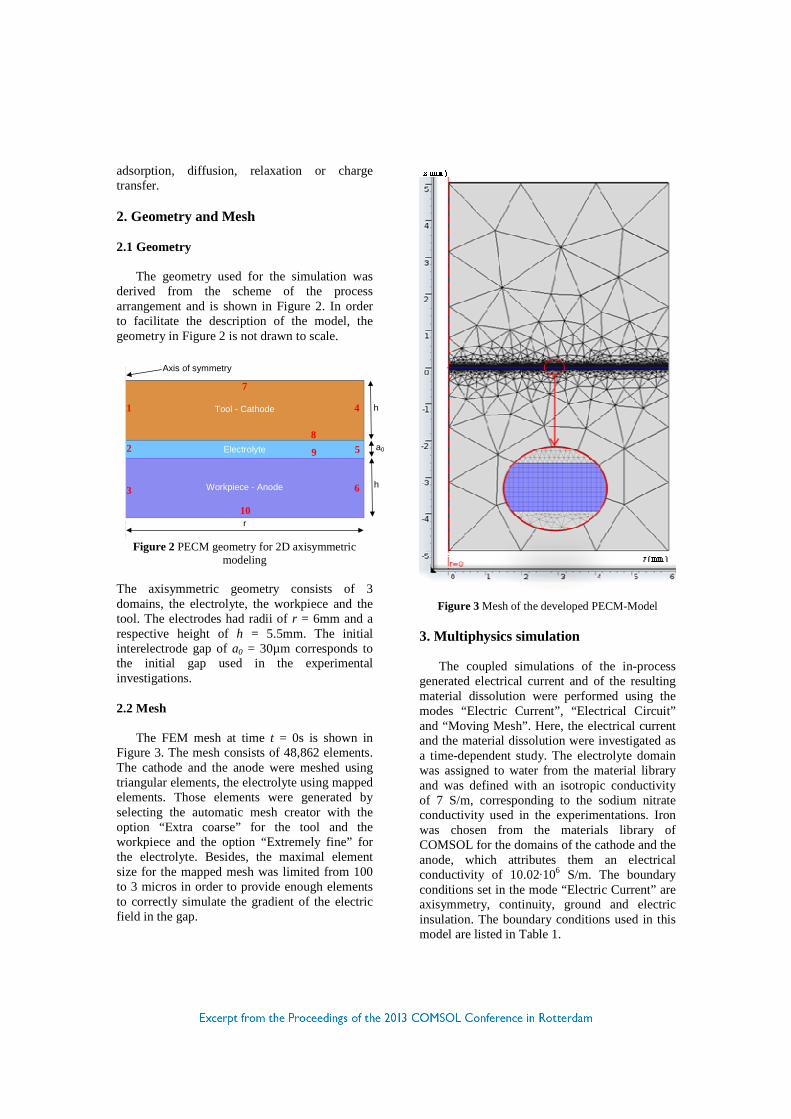
The FEM mesh at time t = 0s is shown in
Figure 3. The mesh consists of 48,862 elements. The cathode and the anode were meshed using triangular elements, the electrolyte using mapped elements. Those elements were generated by selecting the automatic mesh creator with the option “Extra coarse” for the tool and the workpiece and the option “Extremely fine” for the electrolyte. Besides, the maximal element size for the mapped mesh was limited from 100 to 3 micros in order to provide enough elements to correctly simulate the gradient of the electric field in the gap.
Figure 3 Mesh of the developed PECM-Model
3. Multiphysics simulation The coupled simulations of the in-process
generated electrical current and of the resulting material dissolution were performed using the modes “Electric Current”, “Electrical Circuit” and “Moving Mesh”. Here, the electrical current and the material dissolution were investigated as a time-dependent study. The electrolyte domain was assigned to water from the material library and was defined with an isotropic conductivity of 7 S/m, corresponding to the sodium nitrate conductivity used in the experimentations. Iron was chosen from the materials library of COMSOL for the domains of the cathode and the anode, which attributes them an electrical conductivity of 10.02·106 S/m. The boundary conditions set in the mode “Electric Current” are axisymmetry, continuity, ground and electric insulation. The boundary conditions used in this model are listed in Table 1.
Tool - Cathode
Workpiece - Anode
9 Electrolyte
1
2
3
4
5
6
7
8
10
h
h
a0
r
Axis of symmetry
Boundary Definition
1 - 3 Axisymmetry
4 - 6 Insulation
7 Ground
8 Continuity
9 Terminal
10 Insulation
Table 1: Boundary conditions for the boundaries numbered in Figure 2
The electrochemical properties of the
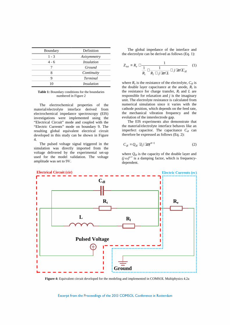
material/electrolyte interface derived from electrochemical impedance spectroscopy (EIS) investigations were implemented using the “Electrical Circuit” mode and coupled with the “Electric Currents” mode on boundary 9. The resulting global equivalent electrical circuit developed in this study can be shown in Figure 4.
The pulsed voltage signal triggered in the simulation was directly imported from the voltage delivered by the experimental set-up used for the model validation. The voltage amplitude was set to 9V.
The global impedance of the interface and the electrolyte can be derived as follows (Eq. 1):
dllt
etot
CjLjRR
RZ⋅⋅+
⋅⋅++
+=ω
ω11
1 (1)
where Re is the resistance of the electrolyte, Cdl is the double layer capacitance at the anode, Rt is the resistance for charge transfer, Rl and L are responsible for relaxation and j is the imaginary unit. The electrolyte resistance is calculated from numerical simulation since it varies with the cathode position, which depends on the feed rate, the mechanical vibration frequency and the evolution of the interelectrode gap.
The EIS experiments also demonstrate that the material/electrolyte interface behaves like an imperfect capacitor. The capacitance Cdl can therefore be expressed as follows (Eq. 2):
1)( −⋅⋅= αωjQC dldl (2)
where Qdl is the capacity of the double layer and (j ·ω)α-1 is a damping factor, which is frequency-dependent.
Figure 4: Equivalent circuit developed for the modeling and implemented in COMSOL Multiphysics 4.2a
Pulsed Voltage
Ground
Rt Re
Rl L
Cdl
Electrical Circuit (cir)
Electric Currents (ec)
The time-dependent simulation of the material dissolution was performed by coupling the described electrical modi with the “Moving Mesh” mode.
The time-dependent position S of the cathode/electrolyte interface - boundary 8 - was moved according to the following equation (Eq. 3):
0)sin(2
atz
tvS f +⋅⋅∆+⋅−= ω (3)
The functional principle of the material
removal under PECM conditions is based on Faraday’s law. The removed material mass m is calculated by Eq. 4:
QFz
Mm ⋅
⋅⋅= η (4)
where η is the material removal efficiency, M the molar mass, z the electrochemical valence of the material, F the Faraday constant and Q the electric charge exchanged between the electrodes. The velocity of the material removal in normal direction can be derived from Eq. 3 and is proportional to the normal current density
nJr
according to Eq. 4:
nn JFz
Mv
rv ⋅⋅⋅
⋅=ρ
η (5)
where ρ is the density of the investigated material. Boundary 9, which should be machined, was assigned to this condition.
The simulated process conditions and the material properties used for the simulations are listed in Table 2 and Table 3.
Name Value
vf Feed rate 0.1mm/s
∆z Vibration amplitude 373µm
T Vibration period 20ms
ton Pulse on-time 3ms and 5ms
χ Phase 50 % and 85 %
U Voltage amplitude 9V
Table 2: Simulated process conditions
Name Value
η Current efficiency 100%
M Molar mass 55.85g/mol
z Valence 2
ρ Mass density 7,30kg/m³
F Faraday constant 9.6·104C/mol
Qdl Pseudo-capacity 2.6·10-4F/s α-1
Rt Charge-transfer resistance 2.2Ω
Rl Relaxation resistance 7.6Ω
L Relaxation inductance 0.14
α Damping exponent 0.8
Table 3: Material properties used for simulation and experiments
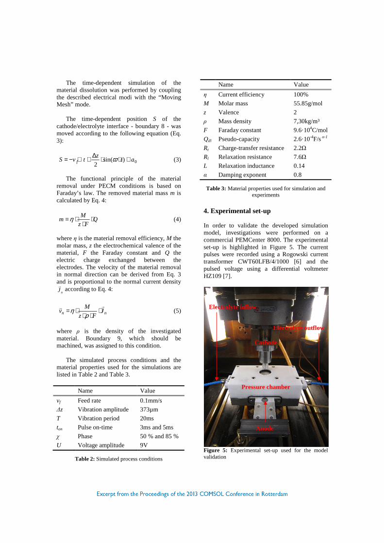
4. Experimental set-up In order to validate the developed simulation model, investigations were performed on a commercial PEMCenter 8000. The experimental set-up is highlighted in Figure 5. The current pulses were recorded using a Rogowski current transformer CWT60LFB/4/1000 [6] and the pulsed voltage using a differential voltmeter HZ109 [7].
Figure 5: Experimental set-up used for the model validation
Cathode
Anode
Pressure chamber
Electrolyte inflow
Electrolyte outflow
5. Results
As explained in chapter 3, the input pulsed voltages used for the numerical simulation were directly taken from the voltage input signal generated by the experimental investigations. The voltage signals are displayed for one period in Figure 6.
Figure 6: Pulsed voltage signal recorded during the experimental investigation and used as input in the simulations
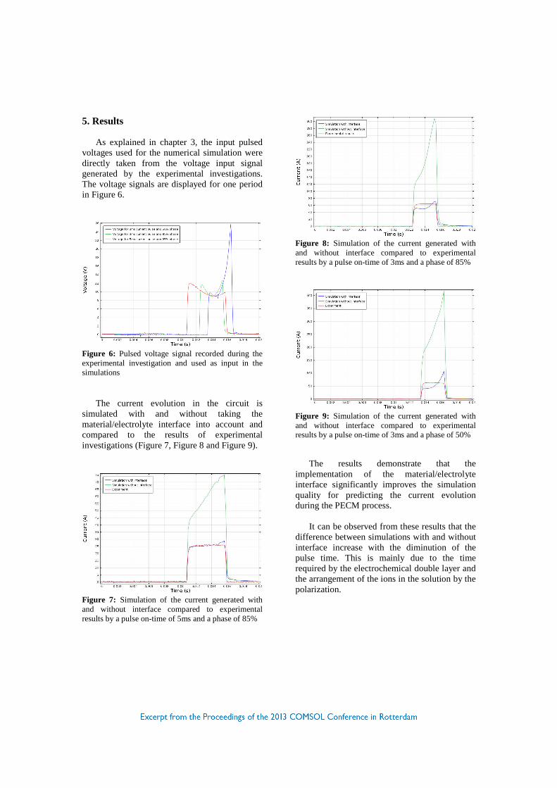
The current evolution in the circuit is simulated with and without taking the material/electrolyte interface into account and compared to the results of experimental investigations (Figure 7, Figure 8 and Figure 9).
Figure 7: Simulation of the current generated with and without interface compared to experimental results by a pulse on-time of 5ms and a phase of 85%
Figure 8: Simulation of the current generated with and without interface compared to experimental results by a pulse on-time of 3ms and a phase of 85%
Figure 9: Simulation of the current generated with and without interface compared to experimental results by a pulse on-time of 3ms and a phase of 50%
The results demonstrate that the implementation of the material/electrolyte interface significantly improves the simulation quality for predicting the current evolution during the PECM process.
It can be observed from these results that the difference between simulations with and without interface increase with the diminution of the pulse time. This is mainly due to the time required by the electrochemical double layer and the arrangement of the ions in the solution by the polarization.
6. Conclusions
In this contribution, a simulation model, which takes into account the material/electrolyte interface, was developed to predict the current evolution and thus the material removal behavior of cast iron by pulse electrochemical machining. Experimental results confirm the simulation very well.
In this model, only electrodynamics and mesh displacement were used. To increase the simulation, the up to now neglected inhomogeneous microstructure and the gas bubbles produced at the electrodes should be implemented. 7. References [1] Rajurkar K.P., Zhu D., McGeough J.A.,
Kozak J., De Silva A., New development in electrochemical machining, Ann. CIRP, 48/2, 567-579 (1999)
[2] O. Weber, H. Natter , A. Rebschläger , D. Bähre, Surface quality and process behavior during Precise Electrochemical Machining of cast iron, Proceedings of the 7th International Symposium on Electrochemical Machining Technology, 41-46 (2011)
[3] O. Weber, R. Kollmannsperger , D. Bähre,
Simulation of the Current Density Distribution and the Material Removal Behavior on the Graphite/Iron-Matrix Interface in Cast Iron under Pulse Electrochemical Machining Conditions, Proceedings of the European COMSOL Conference (2012)
[4] D. Bähre, O. Weber, A. Rebschläger,
Investigation on Pulse Electrochemical Machining Characteristics of Lamellar Cast Iron using a Response Surface Methodology-based Approach, Procedia CIRP, 6, 362-367 (2013)
[5] O. Weber, D. Bähre, A. Rebschläger, Study of Pulse Electrochemical Machining characteristics of spheroidal cast iron using sodium nitrate electrolyte, Proceedings of COMA 13 – International Conference on Competitive Manufacturing, 125-130 (2013)
[6] ADMESS GmbH, “Rogowskispulen CWT-
Serie“, ADMESS GmbH, 2012, [Online]. Available: http://www.admess.de/index.php?dms_id=81&cPath=5_33 _35 [Accessed: August 30, 2012]
[7] Fuchs Elektronik GmbH, “HZ109
Differenz-Tastkopf 10:1 / 10:1”, Fuchs Elektronik GmbH, 2012, [Online]. Available: http://shop.fe-kl.de/Messtechnik/Zubehoer-Messtechnik/HZ109-Differenz-Tastkopf-1-1-10-1::3132.html [Accessed: August 30, 2012]
9. Acknowledgements
This project is co-funded by the European Union through the European Regional Development Fund (ERDF) within the program INTERREG IVa.