modeling and simulation analysis of solar pv energy …
TRANSCRIPT
Venkatesan et al., International Journal of Advanced Engineering Technology E-ISSN 0976-3945
Int J AdvEngg Tech/Vol. VII/Issue II/April-June,2016/770-777
Research Paper
MODELING AND SIMULATION ANALYSIS OF SOLAR PV ENERGY SYSTEM WITH LUO CONVERTER USING
STATE-SPACE AVERAGING TECHNIQUE 1Sundarrajan Venkatesan, 2Manimaran Saravanan
Address for Correspondence 1Assistant Professor, Alagappa chettiar College of Engineering and Technology, Karaikudi, Tamilnadu, India
2Professor, Thiagarajar College of Engineering, Madurai, Tamilnadu, India.
ABSTRACT This paper presents a modeling and simulation analysis of photovoltaic (PV) system with higher order DC-DC LUO converter using state-space averaging technique. The LUO converter has the non-inverting output and its output voltage can be more or less than input voltage with the input current being continuous. The inherent input filtering properties of LUO converter gives better output voltage and current with reduced ripples and increases the efficiency as compared to existing fundamental DC-DC converters. The state-space method is used to model the LUO converter. The PV panel simulink model is developed based on the single diode equivalent circuit of the PV module. The combined PV panel model and state-space model of LUO converter is simulated under varying environmental conditions using MATLAB SIMULINK. Incremental conductance maximum power point tracking (MPPT) algorithm is used to verify the performance of the LUO converter in a PV system. A circuitry simulation is performed under the same test conditions to validate the state-space model. The simulation result shows that state-space averaging technique yields similar performance as the result from circuitry model. The state-space technique is easier to implement as compared to circuit model. In addition, the controller design for converter in PV system with either simple or complex higher order system such as LUO converter is easily possible. KEY WORDS —Higher order power converter, incremental conductance, LUO, MPPT, and state-space averaging method.
1. INTRODUCTION: In recent year more attempts has been made to locate renewable clean energies in the countries all over the world to meet the energy demand. The solar energy will play an important role in alleviating the energy crisis, it decreasing the environmental pollution and improving the green house effect, hence tremendous growth in the past decade. The significant research attention on solar PV energy system is focused because of more reliable and easy to install [1-3]. However, the solar PV energy system has low conversion efficiency, because of the output power of solar cells mainly depends on factors such as temperature and irradiance. To maximize the output power of PV and provide a constant or regulated output voltage, there are a number of MPPT techniques [4] and DC–DC converters are employed and play a vital role in solar PV system [5]. Different MPPT techniques have been developed and published such as hill climbing/ perturb and observe (P&O), incremental conductance (Inc-cond.) method, fractional open circuit voltage, fractional short circuit current, Fuzzy logic and neural networks [6-11].These techniques differ in many aspects such as required sensors, time, complexity of the algorithm to track the MPP, implementation cost and the ease of implementation. Among these most suggested MPPT algorithms hill climbing/ P&O and Inc-cond. algorithm are the center of attention because of their simplicity and ease of implementation. P&O algorithm is not precise enough because it fails to quickly track the MPP under fast varying atmospheric conditions and they perform steady-state oscillations at MPP, which consequently waste the energy [12]. The Inc-cond. method is the one which exhibits better performance than other techniques [13, 14]. In this algorithm, the array terminal voltage is always adjusted according to its value relative to the MPP voltage by measuring the incremental and instantaneous array conductance of the PV module. In DC-DC converter perspective, all existing converter topology used in solar PV-based system such as buck, boost, buck-boost and higher order converters CUK,SEPIC converters have its own unique characteristics and are employed in a number of applications such as electric traction, electric
vehicles, and distributed DC systems such as space stations, ships, and airplanes, [15-17].Most of the applications need extremely low ripple in voltage and current for battery operated portable devices. Basic converters are not suitable for many applications which required lowest ripple, higher and lower output voltage compared to input and high efficiency. The higher order converters such as CUK,SEPIC and LUO converter is better one, but CUK converter produces the output voltage higher or lower than the input voltage , with reverse polarity [18],[19]. The problem can be corrected easily, but this will inevitably lead to the increased in size and cost of the converter. At the same time, the SEPIC and LUO converter does not suffer from this problem. The literature does not have sufficient report of DC-DC LUO converter and its dynamic performance in conjunction with solar PV panel fed energy system. During the past two decades, different modeling of the DC-DC converters has been carried out by researchers to increase the power conversion efficiency in PV system [20-22]. The PWM and averaged switch model strategies are based on equivalent circuit manipulation. The state-space model is the mathematical model that provides a dynamic model of a physical system. In the state-space average (SSA) technique, differential equations for a system are written in canonical form (matrices).Hence, it is convenient for analyzing complicated converter topologies through state space modeling process of higher order converters. In this paper, Inc-cond. algorithm with fixed step size is used for simulation. DC-DC LUO converter topology is considered for analysis and the state-space model for a non-isolated fourth-order DC-DC LUO converter is derived and the result comparisons are made with circuit model in terms of PV and converter output voltage and current for various irradiation conditions and at constant temperature. By using this model, system matrices are derived, and a MATLAB coding is written to extract the relevant transfer functions particularly the audio susceptibility of the converter and control-to-output transfer function of the DC-DC LUO converter and its stability is analyzed through bode plot.

Venkatesan et al., International Journal of Advanced Engineering Technology E-ISSN 0976-3945
Int J AdvEngg Tech/Vol. VII/Issue II/April-June,2016/770-777
2. MATHEMATICAL MODEL FOR PV MODULE: The basic structural unit of a solar module is the PV cells. It is an electrical device that converts the energy of light directly into electricity by the photovoltaic effect. A single diode equivalent circuit model of a solar cell is shown in Fig.1. It is modeled by a current source, a diode and two resistors. The diode is connected in parallel to current source; the photon energy incident on the PV cell generates current. The current source (Iph) is proportional to the amount of energy incident on PV cell [23-25].
Fig.1: Equivalent single diode model of a solar cell
The I-V and PV curves of the PV are obtained by the equation (1-5). The PV cell light generated current Iph depends on the solar irradiation and temperature as given by (1)
)]([ refopisckph TTKIGI (1)
The PV module reverse saturation current is given by
1)(
ops
ocKATN
qVsc
rs
e
II
(2) The module diode saturation current Io varies with the cell temperature and is given by (3)
}11
{*
exp[][ 3
opref
go
ref
op
rsoTTBK
Eq
T
TII
(3) The solar cell output current is given by
shophpv IIII
(4)
Equation (4) can be rewritten by substituting from equation (1-3) and obtained as
]1)}(*[exp{* spvpvoPphPpv RIVqININI
shspvpv RRIV /)( (5)
where Vpv :Output voltage of a PV module (V) Ipv :Output current of a PV module (A) Iph :Light generated current in a PV module (A) Gk :Constant which is equal to µ/1000; µ :Irradiation( Irradiation level) (W/m2) IO :Diode saturation current (A) q :Electron charge (1.6×10⁻¹⁹ C) k :Boltzmann constant (1.38×10⁻²³ J/K) Ki :Temperature co-efficient at short-circuit current ISCr is 0.0017A / oC A=B :p-n junction ideality factor =1.6 Top :Cell operating temperature in ⁰C Tref :Cell reference temperature at 25⁰C Rs :Solar cell series resistance (Ω) Rsh :Solar cell shunt resistance (Ω) ISC :PV module short-circuit current at 25 oC and 1000W/m2 Ego :Band gap for silicon = 1.1 eV Ns :Number of cells connected in series in the module Np :Number of cells connected in parallel in the module
The solar panel output power depends on the voltage and current obtained at its output terminals and there exists one operating voltage at which the solar panel can produce maximum power. A 40W PV module is taken as the reference model for simulation setup,
whose specification details are given in Table1. Fig.2 (a) & (b) presents the current-voltage (I-V) and power-voltage (P-V) characteristics of the PV panel under different solar irradiation condition at a constant temperature of 25oC.
(a)
(b)
Fig 2. (a): I-V and (b) P-V characteristics of 40W solar panel under varying irradiation condition at 25oC.
Table 1 Electrical specification at 1000W/m2and 25oC (40-Watt solar panel)
Parameter Value
Rated power 40W
Voltage at maximum Power(Vmp) 17.4V
Current at maximum Power(Imp) 2.29A
Open circuit voltage(Voc) 21.8V
Short circuit current(Isc) 2.45A
3. MAXIMUM POWER POINT (MPP) TRACKING: 3.1Basics and Load Matching of MPPT Technique: PV module has a maximum power point for a given temperature and insolation. Fig.3 shows the PV module directly interfacing to load. If a load line crosses this point, maximum power would be transferred to the load and it is well known that the P-V characteristics has only one point where power is maximum, and the corresponding voltage is VMPP and current is IMPP. The optimum value of load resistance is obtained by PV voltage and PV current at MPP and is given by equation (6).
Fig.3: PV module directly interfacing to Load
The optimum resistance of PV module is described as
MPP
MPPopt
I
VR
(6) The load resistance of the circuit is,
O
OL
I
VR
(7) where VMPP is the maximum PV voltage at MPP and IMPP is the maximum value of PV current at the MPP, Vo and Io are the converter output voltage and current

Venkatesan et al., International Journal of Advanced Engineering Technology E-ISSN 0976-3945
Int J AdvEngg Tech/Vol. VII/Issue II/April-June,2016/770-777
respectively. When the value of load resistance (RL) matches with that of Ropt maximum power transfer from photovoltaic panel to the load will occur. The objective of the MPPT is to make the load resistance of the PV module to be equal to the optimal resistance of the solar panel.
Lopt RR
In order to achieve the above, and extract the maximum power from PV panel, DC-DC converter is inserted in between the PV panel and load and its duty cycle is varied. In this paper DC-DC LUO converter is used. The voltage gain of the higher order LUO converter is given by
D
D
V
V
in
o
1
where “D” is the duty cycle of the converter. The variation of the duty cycle is not only regulating the output voltage but also can be used to vary the input side impedance of the converter. The DC-DC converter can be controlled to present optimum impedance at the PV array terminals which facilitate maximum power extraction from an array. This feature can be appreciated by inspecting the input side impedance (Rin) expressions for the converters. The input impedance of the higher order DC-DC LUO converter can be calculated by
Lin RD
D
I
V
D
DR
2
0
0
211
(8)
The equation (8) indicates that by changing duty cycle, the input impedance (Rin) of converter should be equal to the optimum impedance (Ropt) at which the system is working at MPP. 3.2 Implementation of Inc-Cond. Method: The Inc-Cond. method is based on the fact that the slope of the PV array power curves as shown in Fig. 4. It is zero at the MPP, positive on the left of the MPP, and negative on the right, as given by
Fig.4: Basic of Inc-Cond. MPPT method ��
��=
�(��)
��= � +
��
��= � + �
∆�
∆� (9)
The equation (9) can be rewritten by, ∆�
∆�= −
�
�;at MPP
∆�
∆�> −
�
�;left of MPP
∆�
∆�< −
�
�;right of MPP
The MPP can thus be tracked by comparing the instantaneous conductance (I/V) to the incremental conductance (ΔI/ΔV) as shown in flowchart as given in Fig.5 for Inc-Cond. algorithm MPPT. Vref is the
reference voltage at which the PV array is forced to operate. At the MPP, Vrefequals to VMPP. Once the MPP is reached, the operation of the PV array is maintained at this point unless a change in ΔI is noted, which is due to the change in atmospheric conditions. The algorithm decrements or increments Vref to track the new MPP. At the MPP, no control action is needed, therefore the adjustment stage will be bypassed and the algorithm will update the stored parameters at the end of the cycle as usual. The Inc-Cond. technique is used the instantaneous conductance and the incremental conductance to generate an error signal
� =�
�+
��
�� (10)
From (10), we know that e goes to zero at the MPP, but it is rarely occurs in practical implementation, and a small error is usually acceptable. In this paper the error value e is taken as 0.02. Measurements of the instantaneous PV array voltage and current require two sensors, which can easily keep track of previous values of voltage and current and make all the decisions as per the flow chart; duty cycle is varied according to the algorithm.
Fig.5: Flowchart of Inc-Cond. algorithm MPPT
4. MODELING OF DC-DC LUO CONVERTER USING STATE-SPACE TECHNIQUE: The state-space-averaging approach [26] is widely used to derive the expressions and analysis for the small-signal characteristics of PWM-controlled DC-DC converters. It consists of state equation and output equation that reveals the characteristics of the particular physical system. It exhibits the dynamic behavior of a system or switching converter using computer simulations, which is very useful in the design of controllers. The operation of the state-space model of the converters are described by the following basic state equations
)()()(
)()()(
tDutCxtY
tButAxtX
(11)
where, x(t) = The state variable, u(t) = The input vector, parameter A is the state matrix, parameter B is the input matrix, C is output matrix and D is the transition matrix. In an electrical system, the method to identify the set of state variables is by identifying the number of

Venkatesan et al., International Journal of Advanced Engineering Technology E-ISSN 0976-3945
Int J AdvEngg Tech/Vol. VII/Issue II/April-June,2016/770-777
energy storage elements. With that, the nth order of the system can also be known. Using this state-space average model of DC–DC converter, one can obtain the small signal model and transfer function of converter, which will be very useful in the design of closed-loop controller using various control techniques [27–28]. The most superior advantages of DC-DC LUO converter is capacitor (C) assures the galvanic insulation between input and output. The short circuit or breakdowns of the load do not affect solar panels. The additional filter elements in the LUO-converter eliminate the output ripples and enhance the output voltage level effectively [29]. However, this type of converter is still under research with regard to its usage in industrial and domestic applications. 4.1 States-Space Equation: Fig.6(a) shows a higher order DC-DC LUO converter, which is used as the power stage interface between the PV module and the load. The LUO converter can operate either in continuous conduction mode (CCM) or discontinuous conduction mode (DCM) depending on the current flowing through L1. In this paper CCM mode of operation is considered. The DC-DC converter has two modes of operation. (i)When the switch S is closed (ON), in this mode, the capacitor releases energy to the output. (ii) When the switch S is in OFF, the current drawn from the source becomes zero, and current iL1 flows through the diode to charge capacitor C1.The equivalent circuit of the LUO converter when switch is ON and OFF state as shown in Fig.6 (b)&(c).
(a)
(b)
(c)
Fig.6: Circuit diagram of (a) LUO converter (b) Switch ON condition (c) Switch OFF condition
The fourth order elementary LUO converter made up of two inductors and two capacitors and capable of working in either step-up or step-down mode. The state variables of the LUO converter (x1, x2, x3, x4) are
considered as currents 1Li and
2Li , voltages 1cV and
2cV respectively.
The state equation derivation for the LUO converter for the ON and OFF state of the switch can be described by the following equations (13) and (16) respectively. These equations are expressed using the switching function, when the switch is ON
22
2
21
1
22
4
1
3
222
2
1
..
11
1
111
1
CL
L
inCC
in
vRC
iC
X
iC
X
vL
vL
vL
X
vL
X
(12)
in
C
C
L
L
C
C
L
L
vL
L
v
v
i
i
RCC
C
LL
v
v
i
i
dt
d
0
0
1
1
10
10
001
0
1100
0000
2
1
22
1
22
2
1
2
1
2
1
2
1
(13) The output equation is expressed by (14),
2
1
2
1
1000
C
C
L
L
o
v
v
i
i
V
(14)
During off state, the state equations are written by (15) using Fig 6(c),
22
1
2
1
22
4
1
3
2
2
1
1
11
1
1
1
CL
L
C
C
vRC
iC
X
iC
X
vL
X
vL
X
(15)
in
C
C
L
L
C
C
L
L
v
v
v
i
i
RCC
C
L
L
v
v
i
i
dt
d
0
0
0
0
10
10
0001
1000
01
00
2
1
2
1
2
1
2
1
22
1
2
1
(16) The output equation, is expressed by
2
1
2
1
1000
C
C
L
L
o
v
v
i
i
V
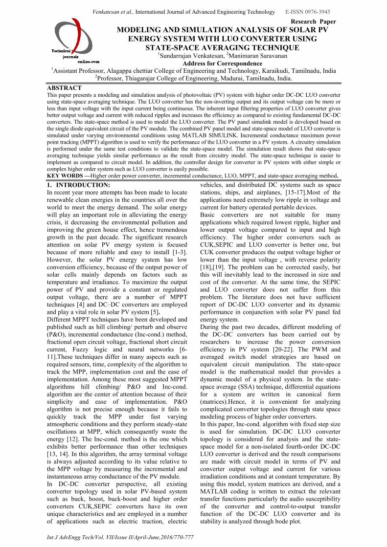
(17) The state-space equations have been implemented in MATLAB/Simulink, where the Simulink block is illustrated in Fig.7 5. SIMULATION RESULTS AND DISCUSSION: In order to validate the state-space model, a circuitry simulation of the proposed PV system is connected in parallel with the state-space model. Both the state-space and circuitry models were developed in MATLAB/Simulink as shown in Fig. 8. The state-space model PV system was simulated under different irradiance conditions. The function of the MPPT block is to ensure that the system delivers the maximum power to the load by varying the duty cycle of the higher order DC-DC LUO converter. The LUO converter is fed by PV source and designed for 40W/24 V, under the nominal maximum point (irradiance G = 1000 W/ m2 and temperature T = 25°C). This output value may change as the
Venkatesan et al., International Journal of Advanced Engineering Technology E-ISSN 0976-3945
Int J AdvEngg Tech/Vol. VII/Issue II/April-June,2016/770-777
Selection of Inductors
max
sL
minin,
1 DfΔI
VL
1
Selection of Capacitors
S1
maxoC1
fC
DIΔV
max
sL
minin,
2 DfΔI
VL
2
2
22
minmax2 8 s
inC
fLC
VDV
(18)
irradiance and temperature level of PV changes. The component of the LUO converter used in the simulation is calculated from the equation (18) and is given in table 2.The DC-DC LUO converter was designed to operate at the switching frequency of 25 kHz.
Table 2 Specification of LUO Converter Components Specifications Inductor, L1& L2 69mH& 19mH
Capacitor,C1&C2 220µF & 47µF
Resistive load, R 15 ohm
Switching frequency 25 kHz
Input voltage 10.5V-17.5V
Output voltage 24V at 1000W/m2
To test the effectiveness of proposed PV system, simulation is done for various environmental conditions. The results of both the state-space averaging and the circuit model provide very much close results. The MPPT tracking features of Inc-Cond MPPT algorithm from 600 to1000 W/m2 at 0.2sec is shown in Fig.9. As the irradiation varies,
the MPPT controller tracks the new maximum power point and the power output of the PV array which is 24W at 600W/m2 is increased to 40W at 1000W/m2. The voltage of the PV module is increased from 15.2V to 17.4V under that condition.
Fig. 7:Open-loop state-space modeling of LUO DC-DC
converter
Fig.8: Overall simulink model of the proposed system
Fig .9:MPPT tracking features of Inc-Cond. MPPT algorithm from 600 to1000W/m2 at 0.2sec
Fig. 10: Simulation results of LUO converter on PV side at 1000W/m2 PV panel voltage and current
0 10 20 30 40 50 60 700
20
40
60
PV Voltage (V)
PV
Pa
nel
Po
wer
(W
)
X Y Plot
Max.Power at 1000w/m2 insolation = 40W
Max.Power at 600w/m2 insolation= 24W
Venkatesan et al., International Journal of Advanced Engineering Technology E-ISSN 0976-3945
Int J AdvEngg Tech/Vol. VII/Issue II/April-June,2016/770-777
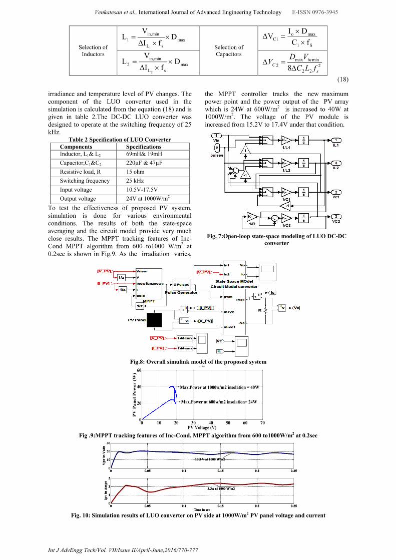
Fig.10 shows the simulation result of PV panel voltage and current at irradiation level of 1000W/m2.It is observed that PV voltage and current at MPP is 17.3V and 2.3 A respectively in steady state. The DC-DC LUO converter provides a dc voltage of 24V and current1.6A for the typical
resistive load of 15 ohms as shown in Fig.11 (a) & (b). The response time of both circuit and state-space model of the proposed system slightly differ, the state-space model is 0.02s faster than the circuit model.
(a)
(b)
Fig.11: The simulation results of LUO converter (irradiance 1000 W/m2) (a) converter output voltage (b) converter output current
(a)
(b)
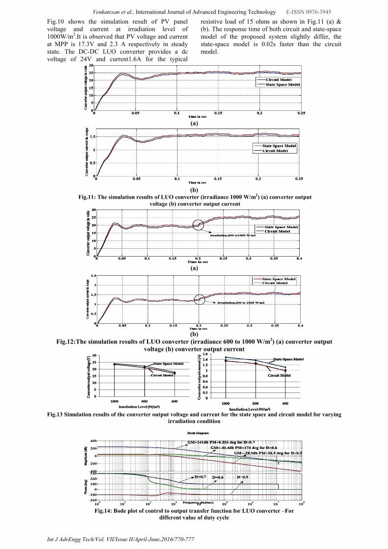
Fig.12:The simulation results of LUO converter (irradiance 600 to 1000 W/m2) (a) converter output voltage (b) converter output current
Fig.13 Simulation results of the converter output voltage and current for the state space and circuit model for varying
irradiation condition
Fig.14: Bode plot of control to output transfer function for LUO converter –For
different value of duty cycle

Venkatesan et al., International Journal of Advanced Engineering Technology E-ISSN 0976-3945
Int J AdvEngg Tech/Vol. VII/Issue II/April-June,2016/770-777
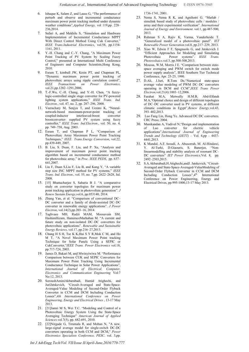
For obtaining the dynamic response of the state-space model system, the irradiance, G, was initially set to 600 and varied to 1000 W/m2 at 0.2sec as shown in Fig.12 and Fig.13 shows the simulation results of the converter output voltage and current for the state space and circuit model for varying irradiation condition. It is observed that for all irradiation levels both converter output voltage and current in circuit and state-space model gives closer result. 5.1 Dynamic Function of the Converter: The dynamic performance indices of the converter are audio susceptibility and control transfer function, where the audio susceptibility of the converter measures the amount of input variations that will reach the output as a function of frequency and the control transfer function describes gain between the control duty ratio and the output variable [30-32]. Audio susceptibility (F) of the LUO converter can be calculated by (19),
(19) The most significant one is, duty cycle-to-output voltage transfer function (GV), which can be obtained by (20)
(20)
inVbbXAAf
DqDqq
DbDbb
DADAA
where
)()(
)1(
)1(
)1(
2121
21
21
21
The system matrices are derived, and a MATLAB M-file coding is written to extract the relevant transfer functions and is given by equation (21) and (22) for D=0.5. The bode plot of control-to-output transfer function for different values of duty cycle D of the LUO converter is shown in Fig.14.The gain margin(GM) and phase margin(PM) are observed from the bode plot. For higher value of the duty cycle where D≥ 0.7, the system get stable as clearly shown in plot for the proposed system. Similarly the bode plot of audio susceptibility (F) of the LUO converter is generated with MATLAB as shown in Fig.15 and observed that for higher value of D is greater than 0.7 the system performance is good, which are significant for feedback control design purpose.
2320214315412
2220
10636238689681785765
426.32
eSeSeSeSe
eSeF
(21)
2320214315412
248
10636238689681785765
37216.35
eSeSeSeSe
eSeGV
(22)
Fig.15: Bode plot of audio susceptibility for LUO converter – For different value of duty cycle
6. CONCLUSION: In order to help the researcher in choosing and analyzing the best converter for solar PV system, this paper reviewed state-space modeling of the non-isolated DC–DC LUO converter with MPPT algorithm. The simulation environment MATLAB/SIMULINK is used to model the circuit, and learnt the dynamic behavior of converter for solar PV system. Simulation results confirmed the accuracy of the obtained model for this complex fourth order system and reduce the overall simulation convergence time as compared to circuit model simulation, since the state-space model does not include the effect of switching. The computation and plotting of typical transfer functions of a DC-DC LUO converter provides ground work for controller design, and bode plots were presented to identify the stability region of the proposed PV system.
REFERENCES 1. Mekhilef S S, Saidur R, and Safari A, “A review on
solar energy use in industries,”Renewable and Sustainable Energy Reviews, vol.15, pp.1777-1790, 2011.
2. Gaetani Marco, et al. “The near future availability of photovoltaic energy in Europe andAfrica in climate-aerosol modeling experiments”. Renewable and Sustainable EnergyReviews, vol.38,pp.706–16,2014.
3. Alemán-Nava Gibrán S, et al. “Renewable energy research progress in Mexico: a review”Renewable and Sustainable Energy Reviews, vol.32, pp.140–53, 2014.
4. Salas V, Olias E,Barrado A, and Lazaro A, “Review of the maximum power point tracking algorithms for stand-alone photovoltaic systems,” Sol. Energy Mater. Sol. Cells, vol. 90, no. 11, pp. 1555–1578, Jul. 2006.
5. Sivakumar S, JagabarSathik M, Manoj P S, and Sundararajan G, “An assessment on performance of DC–DC converters for renewable energy applications”, Renewable and Sustainable Energy Reviews, vol.58,pp.1475–1485,2016.
bASIqSV
SVF
g
o 1)()(
)(
XqqfASIqSd
SVG o
V )()()(
)(21
1
Venkatesan et al., International Journal of Advanced Engineering Technology E-ISSN 0976-3945
Int J AdvEngg Tech/Vol. VII/Issue II/April-June,2016/770-777
6. Ishaque K, Salam Z, and Lauss G, “The performance of perturb and observe and incremental conductance maximum power point tracking method under dynamic weather conditions”,Applied Energy, vol 119,pp. 228–236,2014.
7. Safari A, and Mekhile S, “Simulation and Hardware Implementation of Incremental Conductance MPPT With Direct Control Method Using Cuk Converter,” IEEE Trans.Industrial Electronics, vol.58, pp.1154-1161, 2011.
8. Y.-H. Chang and C.-Y. Chang, "A Maximum Power Point Tracking of PV System by Scaling Fuzzy Control," presented at International Multi Conference of Engineers and Computer Scientists,Hong Kong, 2010.
9. Esram T, kimball JW, Krein PT, and Chapman PL, “Dynamic maximum power point tracking of photovoltaic arrays using ripple correlation control”, IEEE Transactions on Power Electronics, vol.21,pp.1282–1291,2006.
10. T.-F.Wu, C.-H. Chang, and Y.-H. Chen, “A fuzzy-logic-controlled single stage converter for PV-powered lighting system applications,” IEEE Trans. Ind. Electron., vol. 47, no. 2, pp. 287–296, 2000.
11. Veerachary M, Senjyu T, and Uezato K, “Neural-network-based maximum-power-point tracking of coupled-inductor interleaved-boost converter boostconverter- supplied PV system using fuzzy controller,” IEEE Trans. Ind.Electron., vol. 50, no. 4, pp. 749–758, Aug. 2003.
12. Esram T, and Chapman P L, “Comparison of Photovoltaic Array Maximum Power Point Tracking Techniques,” IEEE Trans.Energy Conversion, vol.22, pp.439-449, 2007.
13. B. Liu, S. Duan, F. Liu, and P. Xu, “Analysis and improvement of maximum power point tracking algorithm based on incremental conductance method for photovoltaic array,” in Proc. IEEE PEDS, pp. 637–641,2007.
14. Liu F, Duan S,Liu F, Liu B, and Kang Y, “A variable step size INC MPPT method for PV systems,” IEEE Trans. Ind. Electron., vol. 55, no. 7,pp. 2622–2628, Jul. 2008.
15. [15] Bhattacharjee S, Saharia B J. “A comparative study on converter topologies for maximum power point tracking application in photovoltaic generation”. J Renew Sustain Energy,vol.6, pp.053140, 2014.
16. Zhang Yan, et al. “Comparison of conventional DC–DC converter and a family of diode-assisted DC–DC converter in renewable energy applications”. J Power Electron, vol.14(2),pp.203–16, 2014.
17. Taghvaee MH, Radzi MAM, Moosavain SM, HashimHizam, HamiruceMarhaban M. “A current and future study on non-isolated DC–DC converters for photovoltaic applications”. Renewable and Sustainable Energy Reviews, vol.17, pp.216–27,2013.
18. Chung H S H, Tse K K,Hui S Y R,Mok C M, and Ho M T, “A Novel Maximum Power Point tracking Technique for Solar Panels Using a SEPIC or CukConverter,”IEEE Trans. Power Electronics vol.18, pp.717-724, 2003.
19. James D, Bakari M, and Mwinyiwiwa M. “Performance Comparison between ĆUK and SEPIC Converters for Maximum Power Point Tracking Using Incremental Conductance Technique in Solar Power Applications”, International Journal of Electrical, Computer, Electronics and Communication Engineering Vol:7 No:12, 2013.
20. SoroushAminiAkbarabadi, Hamid Atighechi, and JuriJatskevich, “Circuit-Averaged and State-Space-Averaged-Value Modeling of Second-Order Flyback Converter in CCM and DCM Including Conduction Losses”,4th International Conference on Power Engineering, Energy and Electrical Drives , 13-17 May 2013.
21. [21]Jamri M S, Wei T.C. “Modeling and Control of a Photovoltaic Energy System Using the State-Space Averaging Technique” American Journal of Applied Sciences.vol.7(5), pp. 682-691, 2010.
22. [22]Nirgude G, Tirumala R, and Mohan N, "A new, large-signal average model for single-switch DC-DC converters operating in both CCM and DCM," Power Electronics Specialists Conference, PESC. vol. 3,pp.
1736-1741, 2001.
23. Nema S, Nema R K, and Agnihotri G. “Matlab / simulink based study of photovoltaic cells / modules / array and their experimental verification”. International Journal of Energy and Environment. vol.1, pp.487-500, 2013.
24. Rahman S A, Rajiv K, Varma, Vanderheide T. “Generalized model of a photovoltaic panel”. IET Renewable Power Generation.vol.8, pp.217–229, 2013.
25. Xiao W, Edwin F F, Spagnuolo G, and Jatskevich J. “Efficient Approaches for Modeling and Simulating Photovoltaic Power systems”. IEEE Trans. Photovoltaics.vol.3, pp.500-508,2013.
26. Moussa, W.M, Morris J E. “Comparison between state-space averaging and PWM switch for switch mode power supply analysis”, IEEE Southern Tier Technical Conference, Apr. 25-25, 1990.
27. D.Ali, J.Juri, R.Tom De,“Numerical state-space average value modeling of PWM DC–DC converters operating in DCM and CCM”,IEEE Trans Power Electron,vol.21(4):1003–12,2006.
28. Farahat M.A, Metwally H.M.B, Abd-Elfatah M.A,“Optimal choice and design of different topologies of DC–DC converter used in PV systems, at different climatic conditions in Egypt”,Renew Energy,vol.43, 393–402,2013.
29. Luo Fang Lin, Hong Ye. Advanced DC/DC converters. CRC Press; 2004.
30. Manikandan A, Vadivel N,“Design and implementation of Luo converter for electric vehicle applications”,International Journal of Engineering Trends and Technology (IJETT) – Vol. 4,pp – 4437-4441,2013.
31. K Mandal, A.E Aroudi, A. Abusorrah, M. Al-Hindawi, Y. Al-Turki, D.Giaouris, S. Banerjee, “Non-linearmodelling and stability analysis of resonant DC–DC converters” IET Power Electronics,Vol. 8, pp. 2492–2503,2015.
32. S.A.Akbarabadi,H.Atighechi,andJ. Jatskevich, “Circuit-Averaged and State-Space-Averaged-ValueModeling of Second-Order Flyback Converter in CCM and DCM Including Conduction Losses”,4th International Conference on Power Engineering, Energy and Electrical Drives, pp.995-1000,13-17 May 2013.