modeling and simulation for pv, fuel cell based microgrid under unbalanced loading conditions
DESCRIPTION
Distributed generation has attracted great attention in recent years, thanks to the progress in new-generation technologies and advanced power electronics. The Microgrid has been a successful example by integrating various generation sources with the existing power distribution network through power electronic converters. This paper proposes a PV, Fuel cell based microgrid and a new control strategy for the islanded operation of a multi-bus medium voltage (MV) microgrid. The proposed control strategy of each DG comprises a proportional resonance (PR) controller with an adjustable resonance frequency, a droop control strategy, and a negative-sequence impedance controller (NSIC). The PR and droop controllers are, respectively, used to regulate the load voltage and share the average power components among the DG units. The NSIC is used to effectively compensate the negative-sequence currents of the unbalanced loads and to improve the performance of the overall microgrid system. Moreover, the NSIC minimizes the negative-sequence currents in the MV lines and thus, improving the power quality of the microgrid. The performance of the proposed control strategy is verified with PV, Fuel cell inputs by using digital time-domain simulation studies in the MATLAB/SIMULINK software environmentTRANSCRIPT
International
OPEN ACCESS Journal
Of Modern Engineering Research (IJMER)
| IJMER | ISSN: 2249–6645 | www.ijmer.com | Vol. 4 | Iss. 6| June. 2014 | 15|
Modeling and simulation for PV, Fuel cell Based MICROGRID
under Unbalanced Loading Conditions
T. Venugopal1, B. Bhavsingh
2, D. Vani
3
1 (Electrical And Electronics Engineering, Vaagdevi College Of Engineering,Jntuh,Ap)
2(Electrical And Electronics Engineering, Jayamukhi Institute Of Technological Sciences,Jntuh,Ap)
3 (Electrical And Electronics Engineering, Vaagdevi College Of Engineering,Jntuh,Ap)
I. Introduction MEDIUM voltage (MV) microgrids will play a major role in controlling of distribution network in the
future smart grids. The role of MV microgrids is more important when considering the environmental issues and
economical, social, and political interests. The recently presented concept of multi-microgrids is a motivation
for proposing the concept of the higher voltage level structure of microgrids, e.g., MV level A multi-microgrid
consists of low voltage (LV) microgrids and distributed generation (DG) units connected to several adjacent MV
feeders. Many innovative control techniques have been used for power quality enhanced operation as well as for
load sharing. A microgrid that supplies to a rural area is widely spread and connected to many loads and DGs at
different locations. In general, a DG may have local loads that are very close to it. There may be loads that are
not near to any of the DGs and they must be shared by the DGs and the utility. These are termed as common
load in this paper. The most common method of local load sharing is the droop characteristics. Parallel
converters have been controlled to deliver desired real and reactive power to the system. Local signals are used
as feedback to control the converters, since in a real system, the distance between the converters may make an
inter-communication impractical. The real and reactive power sharing can be achieved by controlling two
independent quantities – the power angle and the fundamental voltage magnitude This paper presents a new
control strategy for an islanded microgrid consisting of several dispatchable electronically-interfaced three-wire
DG units. The microgrid consists of several buses and operates in an MV level. Each DG unit supplies the local
and nonlocal loads which can be unbalanced. The overall microgrid is controlled based on the decentralized
control strategy, i.e., each DG unit is considered as a subsystem equipped with the proposed control strategy.
However, it is assumed that each nonlocal bus (feeder) is equipped with a phase measurement unit (PMU)
which transmits the phasor information of the feeder to the adjacent DG units. The proposed control strategy of
each DG comprises a voltage control loop, a droop controller and a negative-sequence output impedance
controller. The voltage controller adaptively regulates the load voltage using a PR controller. The average power
sharing between the DG units is carried out by the droop controller. However, the droop controller is not able to
share the negative-sequence current resulting from the unbalanced loads. Thus, a new control strategy is
proposed in this paper to efficiently share the negative-sequence current among the DG units. The proposed
Abstract: Distributed generation has attracted great attention in recent years, thanks to the progress
in new-generation technologies and advanced power electronics. The Microgrid has been a successful
example by integrating various generation sources with the existing power distribution network
through power electronic converters. This paper proposes a PV, Fuel cell based microgrid and a new
control strategy for the islanded operation of a multi-bus medium voltage (MV) microgrid. The
proposed control strategy of each DG comprises a proportional resonance (PR) controller with an
adjustable resonance frequency, a droop control strategy, and a negative-sequence impedance
controller (NSIC). The PR and droop controllers are, respectively, used to regulate the load voltage
and share the average power components among the DG units. The NSIC is used to effectively
compensate the negative-sequence currents of the unbalanced loads and to improve the performance
of the overall microgrid system. Moreover, the NSIC minimizes the negative-sequence currents in the
MV lines and thus, improving the power quality of the microgrid. The performance of the proposed
control strategy is verified with PV, Fuel cell inputs by using digital time-domain simulation studies in
the MATLAB/SIMULINK software environment
Key words: Distributed generation, medium voltage (MV) microgrid, negative-sequence current,
power sharing, unbalance load, voltage control.
Modeling And simulation for PV, Fuel cell Based Microgrid Under Unbalanced Loading Conditions
| IJMER | ISSN: 2249–6645 | www.ijmer.com | Vol. 4 | Iss. 6| June. 2014 | 16|
negative-sequence current controller adjusts the negative-sequence output impedance of its own DG such that
the negative-sequence currents of the MV lines will be minimized.
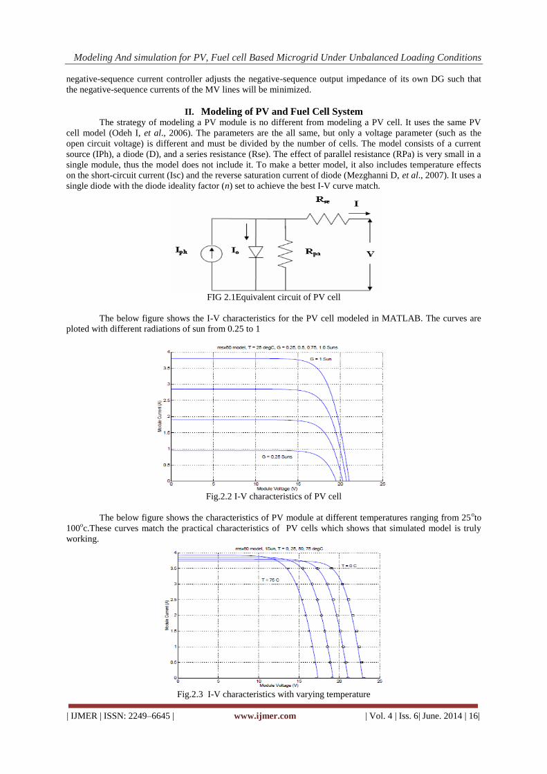
II. Modeling of PV and Fuel Cell System
The strategy of modeling a PV module is no different from modeling a PV cell. It uses the same PV
cell model (Odeh I, et al., 2006). The parameters are the all same, but only a voltage parameter (such as the
open circuit voltage) is different and must be divided by the number of cells. The model consists of a current
source (IPh), a diode (D), and a series resistance (Rse). The effect of parallel resistance (RPa) is very small in a
single module, thus the model does not include it. To make a better model, it also includes temperature effects
on the short-circuit current (Isc) and the reverse saturation current of diode (Mezghanni D, et al., 2007). It uses a
single diode with the diode ideality factor (n) set to achieve the best I-V curve match.
FIG 2.1Equivalent circuit of PV cell
The below figure shows the I-V characteristics for the PV cell modeled in MATLAB. The curves are
ploted with different radiations of sun from 0.25 to 1
Fig.2.2 I-V characteristics of PV cell
The below figure shows the characteristics of PV module at different temperatures ranging from 25oto
100oc.These curves match the practical characteristics of PV cells which shows that simulated model is truly
working.
Fig.2.3 I-V characteristics with varying temperature

Modeling And simulation for PV, Fuel cell Based Microgrid Under Unbalanced Loading Conditions
| IJMER | ISSN: 2249–6645 | www.ijmer.com | Vol. 4 | Iss. 6| June. 2014 | 17|
III. Multi-Bus MV Microgrid Structure
Fig. 1 shows a single-line diagram of a multi-bus MV microgrid which is composed of a 20-kV three-
feeder distribution system and two electronically-coupled three-wire DG units. A combination of balanced and
unbalanced loads are supplied through three radial
Fig.1. MV multi-bus microgrid consisting of two DG Unit
Feeders,F1,F2,F3. The DG units are connected to feeders F1,F2 through step-up transformers and are
assumed to be dispatchable. Thus, each DG unit can supply any amount of the real/reactive power within the
pre-specified limits. Moreover, each DG must control its own power in a decentralized control manner. The
loads are connected to the MV feeders via Y/Δ transformers, and therefore, the loads do not absorb any zero-
sequence current from the MV feeders. Nevertheless, the load current can assume the negative-sequence
component. In this paper, it is assumed that the microgrid system operates in the islanded mode. Therefore, the
DG units are responsible for compensating the negative-sequence current of the unbalanced loads. The
microgrid parameters are given in Table I.
IV. Dynamic Model of a Three-Wire Dg Unit Each DG unit including its series and capacitive (LC) filters can be considered as a subsystem of the
microgird. To control the microgrid using the a decentralized control strategy, it is required that the dynamic
model of each subsystem be derived first. Thus, in this section, the dynamic model of a three-wire DG unit, as a
subsystem of the overall microgrid, is presented. Fig. 2 shows the circuit diagram of a three-wire DG subsystem.
The objective is to design a feedback control system to robustly regulate the load voltages in the presence of
disturbances. It should be noted that since the microgrid system is a three-phase three-wire system, the zero-
sequence of the currents become zero. Thus, using the Clarke transformation, the state space equation of the
system in the stationary reference frame is obtained as follows [16]:
TABLE I
Microgrid System Parameters

Modeling And simulation for PV, Fuel cell Based Microgrid Under Unbalanced Loading Conditions
| IJMER | ISSN: 2249–6645 | www.ijmer.com | Vol. 4 | Iss. 6| June. 2014 | 18|
Fig. 2. Circuit diagram of a three-phase, three-wire DG unit.
The (1) in the Laplace domain is
Equation (4) shows that the matrix transfer function of the DG subsystem is diagonal (completely
decoupled) and can be viewed as two SISO control systems.
V. Operation Principles of the Proposed Control Strategy
The proposed control strategy comprises 1) a voltage control, 2) a power sharing control loop, and 3) a
negative-sequence current controller. The purpose of the voltage control loop is to keep the voltage of each bus
of the microgrid within the acceptable limits. To eliminate the impact of the unknown dynamics (load
dynamics), a feed forward controller is incorporated in the voltage control loop. In the αβ -frame, the reference
signals are sinusoidal, and therefore, a PR controller is designed to ensure the excellent reference tracking [17],
[18]. Moreover, since the frequency is determined by the droop control strategy and may deviate from its rated
value, the proposed PR controller should adaptively adjust its parameters.
When the load is unbalanced, its power components will b oscillatory [19]. In this case, the
conventional droop controller is used for sharing the average power components of the loads and a negative-
sequence output impedance control strategy is proposed to effectively share the oscillatory portions of the load
power. It should be noted that each DG unit mainly compensates the oscillatory power of its local load.
However, the oscillatory power components of the nonlocal loads are shared among all DG units. Therefore, the
proposed control strategy improves the power quality of the overall microgrid. In the following sections, the
control design procedure is explained in detail.
Modeling And simulation for PV, Fuel cell Based Microgrid Under Unbalanced Loading Conditions
| IJMER | ISSN: 2249–6645 | www.ijmer.com | Vol. 4 | Iss. 6| June. 2014 | 19|
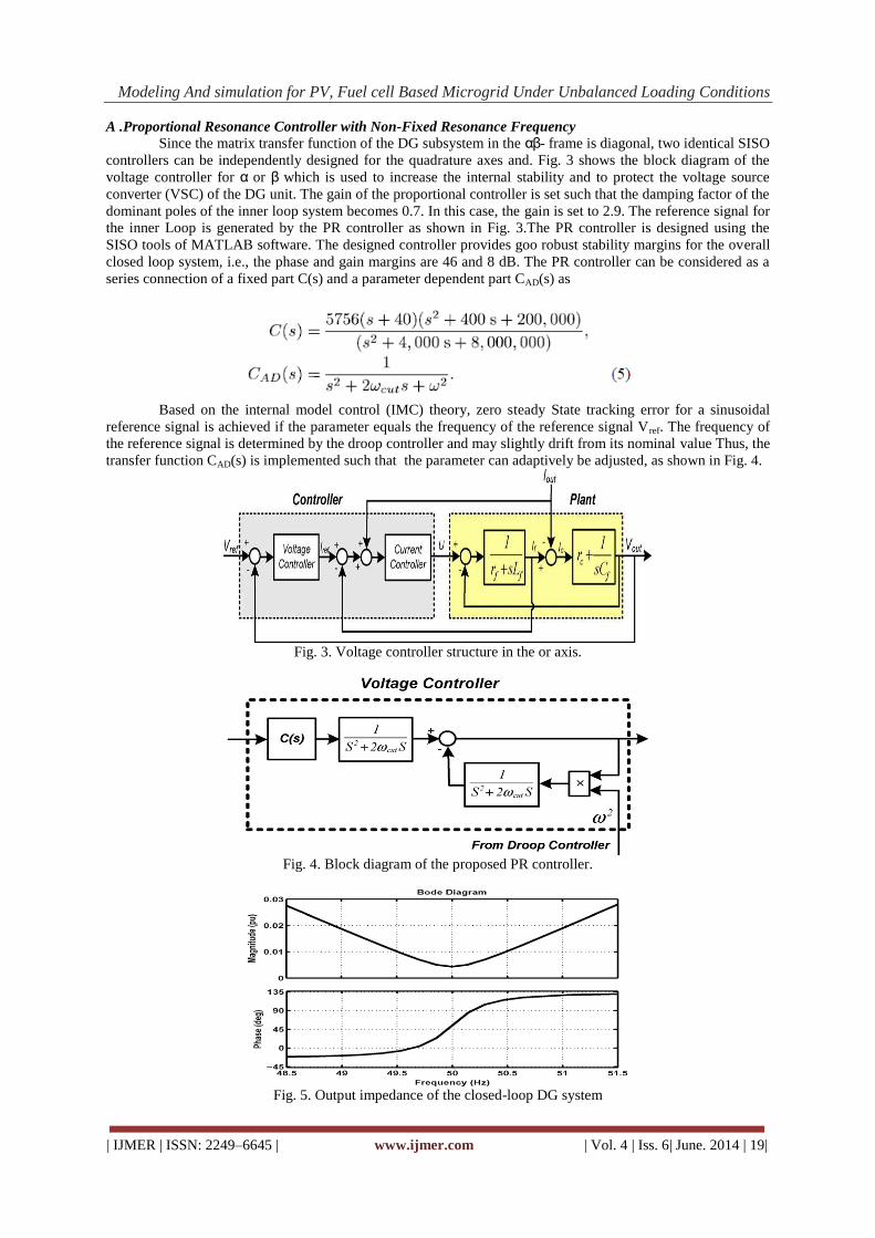
A .Proportional Resonance Controller with Non-Fixed Resonance Frequency
Since the matrix transfer function of the DG subsystem in the αβ- frame is diagonal, two identical SISO
controllers can be independently designed for the quadrature axes and. Fig. 3 shows the block diagram of the
voltage controller for α or β which is used to increase the internal stability and to protect the voltage source
converter (VSC) of the DG unit. The gain of the proportional controller is set such that the damping factor of the
dominant poles of the inner loop system becomes 0.7. In this case, the gain is set to 2.9. The reference signal for
the inner Loop is generated by the PR controller as shown in Fig. 3.The PR controller is designed using the
SISO tools of MATLAB software. The designed controller provides goo robust stability margins for the overall
closed loop system, i.e., the phase and gain margins are 46 and 8 dB. The PR controller can be considered as a
series connection of a fixed part C(s) and a parameter dependent part CAD(s) as
Based on the internal model control (IMC) theory, zero steady State tracking error for a sinusoidal
reference signal is achieved if the parameter equals the frequency of the reference signal Vref. The frequency of
the reference signal is determined by the droop controller and may slightly drift from its nominal value Thus, the
transfer function CAD(s) is implemented such that the parameter can adaptively be adjusted, as shown in Fig. 4.
Fig. 3. Voltage controller structure in the or axis.
Fig. 4. Block diagram of the proposed PR controller.
Fig. 5. Output impedance of the closed-loop DG system
Modeling And simulation for PV, Fuel cell Based Microgrid Under Unbalanced Loading Conditions
| IJMER | ISSN: 2249–6645 | www.ijmer.com | Vol. 4 | Iss. 6| June. 2014 | 20|
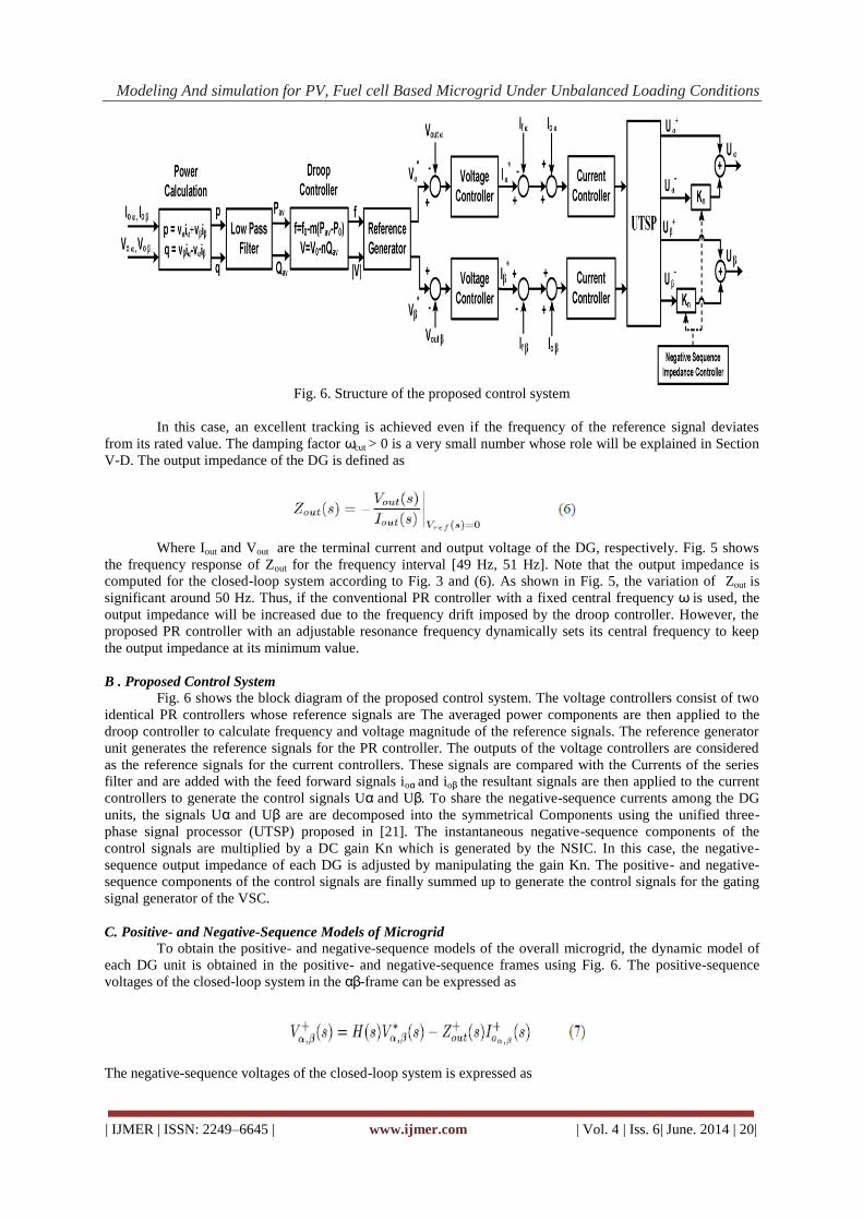
Fig. 6. Structure of the proposed control system
In this case, an excellent tracking is achieved even if the frequency of the reference signal deviates
from its rated value. The damping factor ωcut > 0 is a very small number whose role will be explained in Section
V-D. The output impedance of the DG is defined as
Where Iout and Vout are the terminal current and output voltage of the DG, respectively. Fig. 5 shows
the frequency response of Zout for the frequency interval [49 Hz, 51 Hz]. Note that the output impedance is
computed for the closed-loop system according to Fig. 3 and (6). As shown in Fig. 5, the variation of Zout is
significant around 50 Hz. Thus, if the conventional PR controller with a fixed central frequency ω is used, the
output impedance will be increased due to the frequency drift imposed by the droop controller. However, the
proposed PR controller with an adjustable resonance frequency dynamically sets its central frequency to keep
the output impedance at its minimum value.
B . Proposed Control System
Fig. 6 shows the block diagram of the proposed control system. The voltage controllers consist of two
identical PR controllers whose reference signals are The averaged power components are then applied to the
droop controller to calculate frequency and voltage magnitude of the reference signals. The reference generator
unit generates the reference signals for the PR controller. The outputs of the voltage controllers are considered
as the reference signals for the current controllers. These signals are compared with the Currents of the series
filter and are added with the feed forward signals ioα and ioβ the resultant signals are then applied to the current
controllers to generate the control signals Uα and Uβ. To share the negative-sequence currents among the DG
units, the signals Uα and Uβ are are decomposed into the symmetrical Components using the unified three-
phase signal processor (UTSP) proposed in [21]. The instantaneous negative-sequence components of the
control signals are multiplied by a DC gain Kn which is generated by the NSIC. In this case, the negative-
sequence output impedance of each DG is adjusted by manipulating the gain Kn. The positive- and negative-
sequence components of the control signals are finally summed up to generate the control signals for the gating
signal generator of the VSC.
C. Positive- and Negative-Sequence Models of Microgrid
To obtain the positive- and negative-sequence models of the overall microgrid, the dynamic model of
each DG unit is obtained in the positive- and negative-sequence frames using Fig. 6. The positive-sequence
voltages of the closed-loop system in the αβ-frame can be expressed as
The negative-sequence voltages of the closed-loop system is expressed as
Modeling And simulation for PV, Fuel cell Based Microgrid Under Unbalanced Loading Conditions
| IJMER | ISSN: 2249–6645 | www.ijmer.com | Vol. 4 | Iss. 6| June. 2014 | 21|
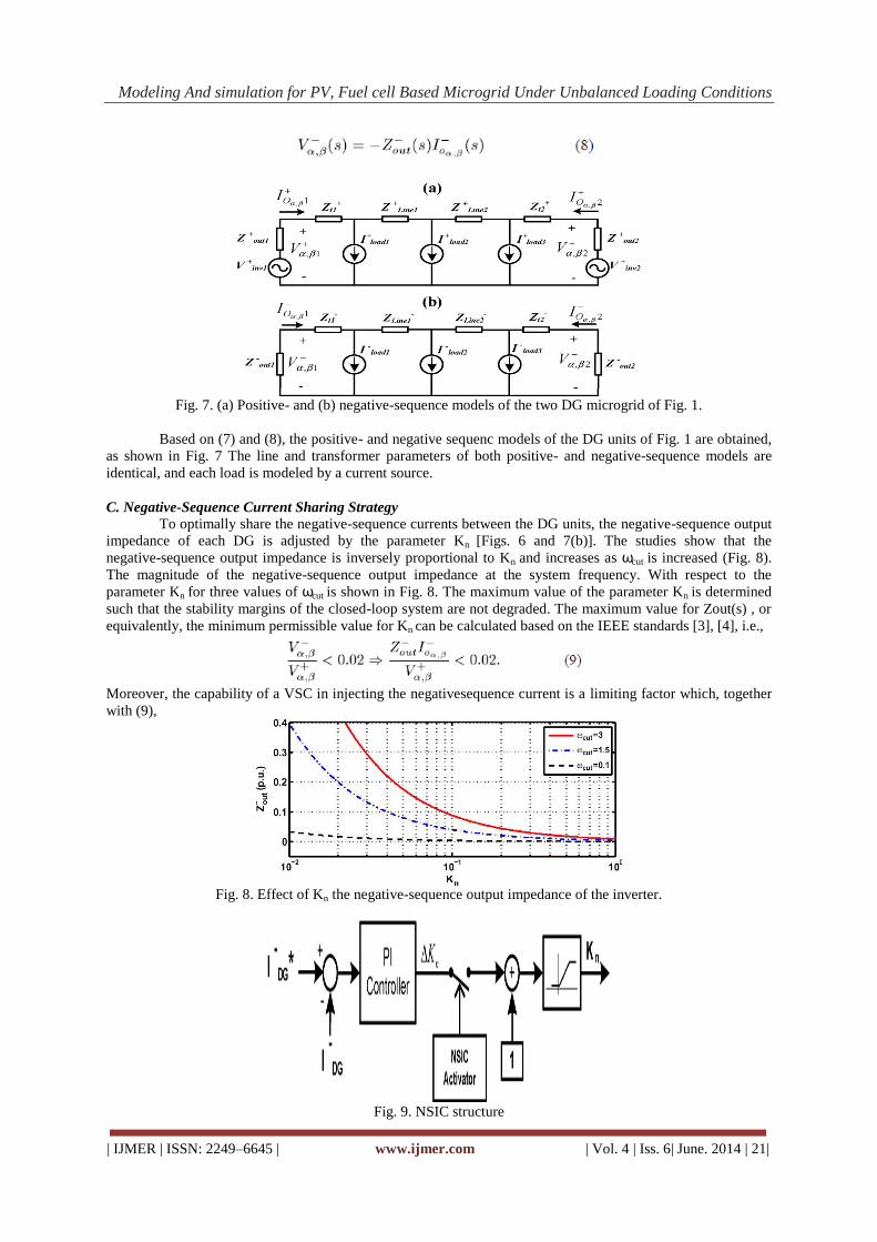
Fig. 7. (a) Positive- and (b) negative-sequence models of the two DG microgrid of Fig. 1.
Based on (7) and (8), the positive- and negative sequenc models of the DG units of Fig. 1 are obtained,
as shown in Fig. 7 The line and transformer parameters of both positive- and negative-sequence models are
identical, and each load is modeled by a current source.
C. Negative-Sequence Current Sharing Strategy
To optimally share the negative-sequence currents between the DG units, the negative-sequence output
impedance of each DG is adjusted by the parameter Kn [Figs. 6 and 7(b)]. The studies show that the
negative-sequence output impedance is inversely proportional to Kn and increases as ωcut is increased (Fig. 8).
The magnitude of the negative-sequence output impedance at the system frequency. With respect to the
parameter Kn for three values of ωcut is shown in Fig. 8. The maximum value of the parameter Kn is determined
such that the stability margins of the closed-loop system are not degraded. The maximum value for Zout(s) , or
equivalently, the minimum permissible value for Kn can be calculated based on the IEEE standards [3], [4], i.e.,
Moreover, the capability of a VSC in injecting the negativesequence current is a limiting factor which, together
with (9),
Fig. 8. Effect of Kn the negative-sequence output impedance of the inverter.
Fig. 9. NSIC structure
Modeling And simulation for PV, Fuel cell Based Microgrid Under Unbalanced Loading Conditions
| IJMER | ISSN: 2249–6645 | www.ijmer.com | Vol. 4 | Iss. 6| June. 2014 | 22|
determine the maximum value of the negative-sequence output impedance. Fig. 9 shows the block diagram of
the NSIC whose reference signal is
Where Iloc, is the negative-sequence current of the local load, is the phase difference between Iloc and Inonioc:
In(11),Imaxdg, is the maximum negative-sequence current that the th DG can inject, and is the
amplitude of the negative-sequence current of the feeder supplying the nonlocal loads. It should be noted that if
the impedances of the MV lines from the nonlocal loads to the adjacent feeders supplied by the DGs are known,
the negative-sequence of output impedance can be adjusted by parameter in an offline manner. However, to
achieve optimal sharing of the negative-sequence current, it is required that the phasor of the negative-sequence
current of each nonlocal load is measured and transmitted to all DG units. This can be performed by a low
bandwidth communication link. In the context of the smart microgrids, the phase measurement units (PMUs) are
used for this purpose. In the study system of Fig. 1, the PMUs are located at the 20-kV side of load transformers.
One of the main advantages of the proposed method over the existing control strategies, i.e., [12]–[15], is that
the phase-angle of the negative-sequence currents of the feeders are considered in the control loop. In some
cases, therefore, the negative- sequence currents of the loads may cancel the effect of each other. In such cases,
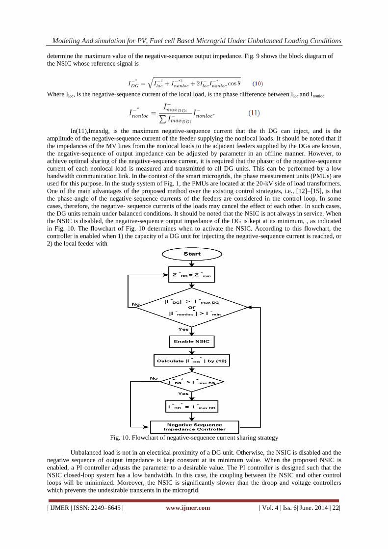
the DG units remain under balanced conditions. It should be noted that the NSIC is not always in service. When
the NSIC is disabled, the negative-sequence output impedance of the DG is kept at its minimum, , as indicated
in Fig. 10. The flowchart of Fig. 10 determines when to activate the NSIC. According to this flowchart, the
controller is enabled when 1) the capacity of a DG unit for injecting the negative-sequence current is reached, or
2) the local feeder with
Fig. 10. Flowchart of negative-sequence current sharing strategy
Unbalanced load is not in an electrical proximity of a DG unit. Otherwise, the NSIC is disabled and the
negative sequence of output impedance is kept constant at its minimum value. When the proposed NSIC is
enabled, a PI controller adjusts the parameter to a desirable value. The PI controller is designed such that the
NSIC closed-loop system has a low bandwidth. In this case, the coupling between the NSIC and other control
loops will be minimized. Moreover, the NSIC is significantly slower than the droop and voltage controllers
which prevents the undesirable transients in the microgrid.
Modeling And simulation for PV, Fuel cell Based Microgrid Under Unbalanced Loading Conditions
| IJMER | ISSN: 2249–6645 | www.ijmer.com | Vol. 4 | Iss. 6| June. 2014 | 23|
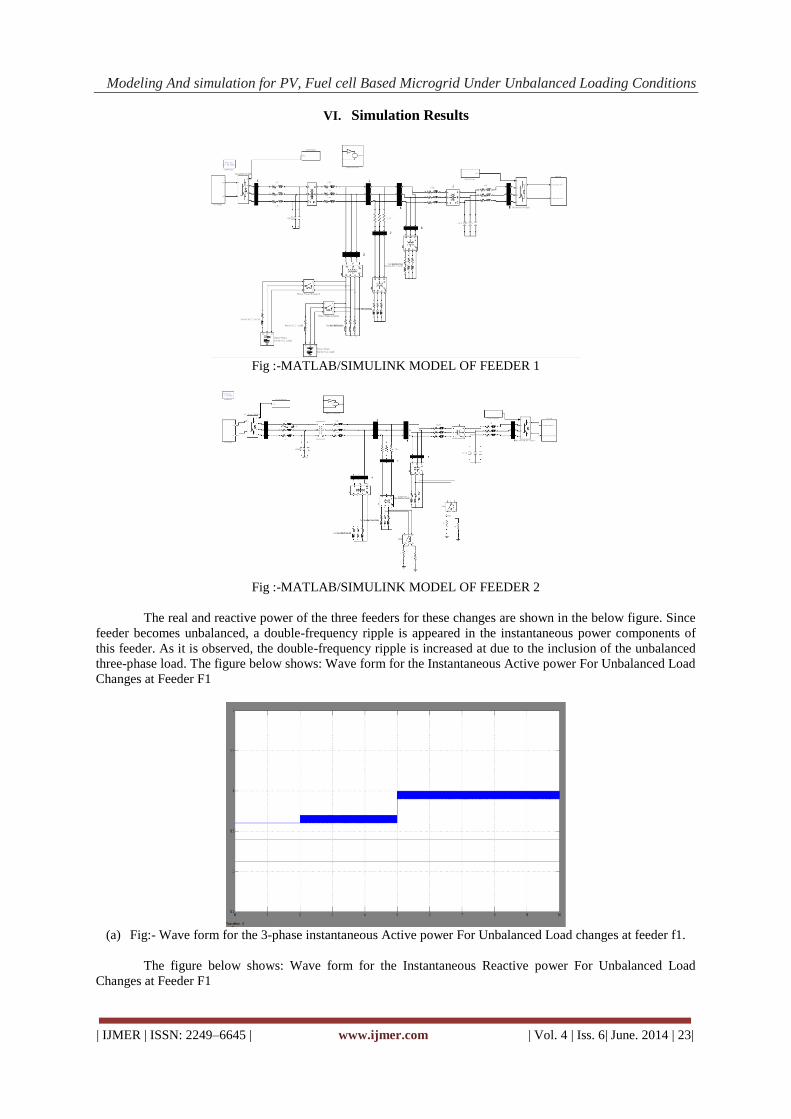
VI. Simulation Results
Fig :-MATLAB/SIMULINK MODEL OF FEEDER 1
Fig :-MATLAB/SIMULINK MODEL OF FEEDER 2
The real and reactive power of the three feeders for these changes are shown in the below figure. Since
feeder becomes unbalanced, a double-frequency ripple is appeared in the instantaneous power components of
this feeder. As it is observed, the double-frequency ripple is increased at due to the inclusion of the unbalanced
three-phase load. The figure below shows: Wave form for the Instantaneous Active power For Unbalanced Load
Changes at Feeder F1
(a) Fig:- Wave form for the 3-phase instantaneous Active power For Unbalanced Load changes at feeder f1.
The figure below shows: Wave form for the Instantaneous Reactive power For Unbalanced Load
Changes at Feeder F1
Modeling And simulation for PV, Fuel cell Based Microgrid Under Unbalanced Loading Conditions
| IJMER | ISSN: 2249–6645 | www.ijmer.com | Vol. 4 | Iss. 6| June. 2014 | 24|
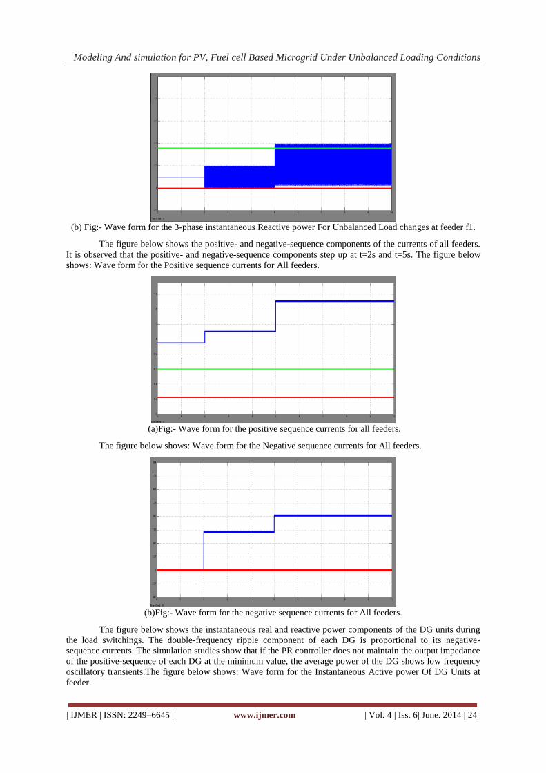
(b) Fig:- Wave form for the 3-phase instantaneous Reactive power For Unbalanced Load changes at feeder f1.
The figure below shows the positive- and negative-sequence components of the currents of all feeders.
It is observed that the positive- and negative-sequence components step up at t=2s and t=5s. The figure below
shows: Wave form for the Positive sequence currents for All feeders.
(a)Fig:- Wave form for the positive sequence currents for all feeders.
The figure below shows: Wave form for the Negative sequence currents for All feeders.
(b)Fig:- Wave form for the negative sequence currents for All feeders.
The figure below shows the instantaneous real and reactive power components of the DG units during
the load switchings. The double-frequency ripple component of each DG is proportional to its negative-
sequence currents. The simulation studies show that if the PR controller does not maintain the output impedance
of the positive-sequence of each DG at the minimum value, the average power of the DG shows low frequency
oscillatory transients.The figure below shows: Wave form for the Instantaneous Active power Of DG Units at
feeder.

Modeling And simulation for PV, Fuel cell Based Microgrid Under Unbalanced Loading Conditions
| IJMER | ISSN: 2249–6645 | www.ijmer.com | Vol. 4 | Iss. 6| June. 2014 | 25|
(a)Fig:- 3-phase Instantaneous Active Powers of DG Units at feeder f1.
The figure below shows: Wave form for the Instantaneous Reactive powers Of DG Units at feeder f1.
(b)Fig:- Wave form for the 3-phase Instantaneous Reactive Power Of DG Units at feeder f1.
Figs. 3(a&b) and 4(a&b) shows the instantaneous power components and the positive- and negative-
sequence current components of the three feeders, respectively. Subsequent to the load switching event at
t=2s,theDG units activate their NSICs to share the demanded negative-sequence current by feeder f3 after 0.9 s.
In this case, the phasor f3 is measured by a PMU and transmitted to the adjacent DG units. The reference signal
of the NSIC of each DG unit is calculated.The figure below shows: Wave form for the Instantaneous Active
power at feeder f1,f2 and f3.
Fig 3(a):- Wave form for the 3-phase instantaneous Active power at f1,f2 and f3.
The figure below shows: Wave form for the Instantaneous Reactive power at feeder f1,f2 and f3.
Modeling And simulation for PV, Fuel cell Based Microgrid Under Unbalanced Loading Conditions
| IJMER | ISSN: 2249–6645 | www.ijmer.com | Vol. 4 | Iss. 6| June. 2014 | 26|
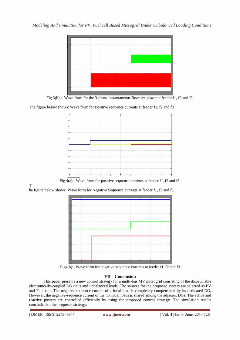
Fig 3(b) :- Wave form for the 3-phase instantaneous Reactive power at feeder f1, f2 and f3.
The figure below shows: Wave form for Positive sequence currents at feeder f1, f2 and f3
Fig 4(a):- Wave form for positive sequence currents at feeder f1, f2 and f3.
T
he figure below shows: Wave form for Negative Sequence currents at feeder f1, f2 and f3
Fig4(b):- Wave form for negative sequence currents at feeder f1, f2 and f3
VII. Conclusion
This paper presents a new control strategy for a multi-bus MV microgrid consisting of the dispatchable
electronically-coupled DG units and unbalanced loads. The sources for the proposed system are selected as PV
and Fuel cell. The negative-sequence current of a local load is completely compensated by its dedicated DG.
However, the negative-sequence current of the nonlocal loads is shared among the adjacent DGs. The active and
reactive powers are controlled efficiently by using the proposed control strategy. The simulation results
conclude that the proposed strategy:
Modeling And simulation for PV, Fuel cell Based Microgrid Under Unbalanced Loading Conditions
| IJMER | ISSN: 2249–6645 | www.ijmer.com | Vol. 4 | Iss. 6| June. 2014 | 27|
• robustly regulates voltage and frequency of the microgrid;
• is able to share the average power among the DGs;
• effectively compensates the negative-sequence currents of local loads; and
• shares the negative-sequence current of the nonlocal loads such that the power quality of the overall
microgrid is not degraded.
REFERENCES [1] N. Hatziargyriou, H. Asano, R. Iravani, and C. Marnay, “Microgrids,” IEEE Power Energy Mag., vol. 5, pp. 78–94,
Jul.–Aug. 2007.
[2] A. G. Madureira and J. A. P. Lopes, “Coordinated voltage support in distribution networks with distributed
generation and microgrids,” IET Renew. Power Gener., vol. 3, pp. 439–454, Sep. 2009.
[3] IEEE Recommended Practice for Monitoring Electric Power Quality, IEEE Std. 1159, 2009.
[4] IEEE Recommended Practice for Electric Power Distribution for Industrial Plants, ANSI/IEEE Std. 141, 1993.
[5] R. Lasseter, “Microgrids,” in Proc. IEEE Power Eng. Soc. Winter Meeting, 2002, pp. 305–308.
[6] M. H. J. Bollen and A. Sannino, “Voltage control with inverter-based distributed generation,” IEEE Trans. Power
Del., vol. 20, no. 1, pp. 519–520, Jan. 2005.
[7] M. C. Chandrokar, D. M. Divan, and B. Banerjee, “Control of distributed ups systems,” in Proc. 25th Annu. IEEE
PESC, 1994, pp. 197–204.
[8] E. A. A. Coelho, P. C. Cortizo, and P. F. D. Garcia, “Small signal stability for parallel-connected inverters in stand-
alone ac supply systems,” IEEE Trans. Ind. Appl., vol. 38, pp. 33–542, Mar./Apr. 2002.
[9] N. L. Soultanis, A. I. Tsouchnikas, N. D. Hatziargyriou, and J. Mahseredjian, “Dynamic analysis of inverter
dominated unbalanced lv micro-grids,” IEEE Trans. Power Syst., vol. 22, no. 1, pp. 294–304, Feb. 2007.
[10] Y. Li, D. M. Vilathgamuwa, and P. C. Loh, “Design, analysis, and realtime testing of a controller for multibus
microgrid system,” IEEE Trans. Power Electron., vol. 19, pp. 1195–1204, Sep. 2004.
[11] T. L. Lee and P. T. Cheng, “Design of a new cooperative harmonic filtering strategy for distributed generation
interface converters in an islanding network,” IEEE Trans. Power Electron., vol. 22, pp. 1919–1927, Sep. 2007.
[12] P. Cheng, C. Chen, T. Lee, and S. Kuo, “A cooperative imbalance compensation method for distributed-generation
interface converters,”
[13] M. B. Delghavi and A. Yazdani, “Islanded-mode control of electronically coupled distributed-resource units under
unbalanced and nonlinear load conditions,” IEEE Trans. Power Del., vol. 26, no. 2, pp. 661–673, Apr. 2011.
[14] D. De and V. Ramanarayanan, “Decentralized parallel operation of inverters sharing unbalanced and non-linear
loads,” IEEE Trans. Power Electron., vol. 25, pp. 3015–3025, Aug. 2010.
[15] R. Majumder, A. Ghosh, G. Ledwich, and F. Zare, “Load sharing and power quality enhanced operation of a
distributed microgrid,” IET Renew. Power Gener., vol. 3, no. 2, pp. 109–119, 2009.
[16] M. N. Marwali and A. Keyhani, “Control of distributed generation systems- part i: Voltages and currents control,”
IEEE Trans. Power Electron., vol. 19, pp. 1541–1550, Nov. 2004.
[17] A. Timbus, M. Liserre, R. Teodorescu, P. Rodriguez, and F. Blaabjerg, “Evaluation of current controllers for
distributed power generation systems,” IEEE Trans. Power Electron., vol. 24, pp. 654–664, Mar. 2009.
[18] H. Karimi, A. Yazdani, and R. Iravani, “Robust control of an autonomous four-wire electronically-coupled
distributed generation unit,” IEEE Trans. Power Del., vol. 26, no. 1, pp. 455–466, Jan. 2011.
[19] H. Akagi, E. H. Watanabe, and M. Aredes, Instantaneous Power Theory and Applications to Power Conditioning.
New York: Wiley, 2007.
[20] M. C. Chandorkar, D. M. Divan, and R. Adapa, “Control of parallel connected inverters in standalone ac supply
systems,” IEEE Trans. Ind. Appl., vol. 29, no. 1, pp. 136–143, Jan.–Feb. 1993.
[21] M. Karimi-Ghartemani and H. Karimi, “Processing of symmetrical components in time-domain,” IEEE Trans. Power
Syst., vol. 22, no. 2, pp. 572–579, May 2007.
Mr.T.Venugopal iscurrently Associate Professor in the Department of Electrical
and Electronics Engineering,Vaagdevi college of engineering ,warangal, India.
He graduated and also persued M.Tech from JNTUH his area of intrests include
Energy management , Distributed Generation, power electronics in
volvemachine drives and power systems etc,
Modeling And simulation for PV, Fuel cell Based Microgrid Under Unbalanced Loading Conditions
| IJMER | ISSN: 2249–6645 | www.ijmer.com | Vol. 4 | Iss. 6| June. 2014 | 28|
Mr.B.Bhavsingh is currently assistant professor in the Departmentof Electrical
and Electronics Engineering,Jayamukhi institute of technological sciences
,Warangal. He received the M.tech Degree in Power Electronics From vaagdevi
college of engineering,Warangal,in2012. He has teaching Experience Of 3 yrs
in SRR and Jayamukhi Institute Of Technological Sciences(JNTUH) ,
Warangal A.P His Interests Include DG’s , Microgrids And Renewable energy
resources.
D.Vani received the B.Tech Degree in Electrical And Electronics Engineering
From NIGAMA Engineering college (JNTUH),Karimnagar, A.P in 2012.He is
currently perusing the M.Tech Degree in Power Electronics in vaagdevi
college of engineering (JNTUH) , Warangal A.P and Interests Include DG’s ,
Microgrids And Power electronics Operation And Control