model sp4012 - carlton professional tree equipment · model sp4012 equipped with a 35hp ... also...
TRANSCRIPT

01-SP4012BS-COVER_a.doc
Model SP4012 Equipped with a 35HP Briggs and Stratton Engine
Machine Serial # _____________ Engine Model & Spec # _____________ Engine Serial # _____________ Purchase Date _____________ Dealer _____________
Carlton J.P.Carlton Company Div. D.A.F. Inc. 121 John Dodd Road Spartanburg, SC 29303 Ph. (864) 578-9335 Fax (864) 578-0210 www.stumpcutters.com


DIESEL ENGINE EXHAUST WARNING
02-CA Prop 65.doc
CALIFORNIA
Proposition 65 Warning Diesel engine exhaust and some of its constituents are known to the State of California to cause cancer, birth defects, and other reproduction harm.


SP4012 SAFETY ALERT
03-Safety Alert.doc


SP4012 SAFETY ALERT
03-Safety Alert.doc


SP4012 SAFETY ALERT
03-Safety Alert.doc


SP4012 SAFETY ALERT
03-Safety Alert.doc
DIESEL MACHINES ONLY


STUMP GRINDER LIMITED WARRANTY J.P. Carlton Co. Inc., hereafter referred to as the “Manufacturer”, warrants each new Carlton Grinder to be free of defects in workmanship and material for a period of one year. This warranty takes effect upon delivery to the original retail purchaser. The manufacturer, at its option, will replace or repair, at a point designated by the manufacturer, any parts which appear to have been defective in material or workmanship. The manufacturer is not responsible for consequential damages. This warranty will not apply if the grinder is not operated in a manner recommended by the manufacturer. The following examples would void warranty: 1. The grinder has been abused. 2. The machine is involved in or damaged by an accident. 3. Repairs or attempted repairs were made without prior written authorization. 4. Including but not limited to repairs made due to normal wear. The owner is responsible for all regular maintenance as explained in the operators’ manual. Neglect in regular maintenance or failure to replace normal wear items such as teeth, pockets, lubrication oils, filters, belts, bearings, etc. may void warranty. This warranty is expressly in lieu of any other warranties, expressed or implied, including any implied warranty or merchantability of fitness for a particular purpose and of any non-contractual liabilities including product liabilities based upon negligence or strict liability. J.P. Carlton Co. Inc. will not be liable for consequential damages resulting from breach of warranty. IT IS NECESSARY TO RETURN THE WARRANTY VALIDATION FORM AND NOTIFY J.P. CARLTON CO. INC. IN WRITING WITHIN TEN (10) DAYS FROM DELIVERY DATE TO VALIDATE THIS WARRANTY. NOTE: This warranty applies only to new and unused equipment or parts thereof manufactured by J.P. Carlton Co. Inc. ANY MACHINES USED FOR LEASE OR RENTAL - WARRANTY IS LIMITED TO 90 DAYS FROM FIRST DAY OF INITIAL SERVICE. NOTICE: All power units and associated components are NOT warranted by J.P. Carlton Co. Inc. or their dealers. It is the customers’ responsibility to return machine to the local engine distributor. INFORMATION PHONE NUMBERS TO FIND YOUR LOCAL ENGINE & PARTS SERVICE CENTERS: Honda ............................................ 1-770-497-6400 (GA-Eastern Time Zone) Kohler Engines.............................. 1-800-544-2444 (Toll Free) Briggs & Stratton Engines ........... 1-800-233-3723 (Toll Free) Lombardini ................................... 1-770-623-3554 (GA-Eastern Time Zone) Deutz Engines................................ 1-800-241-9886 (Toll Free) John Deere Engines ...................... 1-800-533-6446 (Toll Free) Caterpillar ..................................... 1-877-636-7658 (Toll Free) Kubota ........................................... 1-847-955-2500 (IL-Central Time Zone) Kawasaki Engines......................... 1-616-949-6500 (MI-Eastern Time Zone) Wisconsin Engines ........................ 1-800-932-2858 (Toll Free) Onan Engine ................................. 1-800-888-6626 (Toll Free) In order to process any warranty claims, it is the owners’ responsibility to report claims promptly to us or our authorized dealer from whom the equipment was purchased. It is necessary to include the following information on any and all request for warranty:
1. Dealer from whom purchased 2. Date of delivery 3. Serial number of unit 4. Model number of unit
5. Engine make and serial number 6. Length of time in use 7. Date of failure 8. Nature of failure


STUMP GRINDER LIMITED WARRANTY
EXPLANATION OF LIMITED WARRANTY
The manufacturer will not reimburse the customer or dealer labor cost incurred for installing “bolt-on” or “slip-on” items, such as pumps and motors, bearings, belts, pulleys, etc. The manufacturer will provide replacement parts at no cost to the customer for defective parts during the warranty period. Defective parts must be returned to J.P. Carlton Company. It will be the customers’ responsibility to install the replacement parts unless arrangements are made with the selling dealer. The manufacturer will not reimburse travel cost to servicing dealer. It is the customers’ responsibility to deliver machine to dealers facility, unless other arrangements have been agreed to between the selling dealer and the customer. The manufacturer may elect, at its discretion, to reimburse reasonable labor cost to customer or dealer for major defect repairs. Prior approval must be obtained from J.P. Carlton Company Inc.
IMPORTANT NOTICE
1. AIR FILTER MAINTENANCE IS CRITICAL ON STUMP GRINDING MACHINES. DIRT INGESTION WILL NOT BE WARRANTED BY THE ENGINE MANUFACTURER OR J.P. CARLTON COMPANY.
2. OIL AND OIL FILTER MAINTENANCE AND STAYING
WITHIN THE LIMITS OF THE ANGLE OF OPERATION IS ALSO CRITICAL ON STUMP GRINDING MACHINES. STARVING THE ENGINE FOR OIL WILL NOT BE WARRANTED BY THE ENGINE MANUFACTURER OR J.P. CARLTON COMPANY.


Warranty Validation Form Congratulations on your purchase of a Carlton Stump Grinder. This product has been designed and manufactured to provide years of profitable service while minimizing maintenance and downtime. Please take the time now to complete this warranty validation form. This information is necessary for Carlton to instate your warranty. Return Form To: J.P. Carlton Company, Div. D.A.F. Inc. 121 John Dodd Road
Spartanburg, SC 29303 Phone: 1-864-578-9335
Purchaser Information: Company Name:_______________________ Street Address:_____________________________ City:_________________________ State:__________ Zip Code:__________________________ Telephone:_______________________Contact:________________________________________ Machine Information: Model Number :_______________________ Engine Model :________________________ Serial Number :________________________ Serial Number :________________________ Dealer Information: Dealer Name:____________________ Street Address:___________________________ City: _______________________ State:__________ Zip Code:____________________ Contact Name: ____________________ 1. ______ Customer has been instructed on operation and safety aspects of operating the equipment. 2. ______ Customer has been advised not to reach into cutter wheel area. 3. ______ Customer has been advised to stop machine and remove key before performing any type of
maintenance. 4. ______ Customer has been warned not to operate the machine without the cutter wheel guard in place. 5. ______ Customer has been furnished with all parts and operators manuals. 6. ______ Customer has been instructed on equipment maintenance schedules and procedures. 7. ______ Customer has been advise that the engine or power unit that is used on this machine is warranted by
the engine manufacturer and NOT J.P. Carlton Company. All engine warranty issues should be addressed to the local engine dealer.
8. ______ Customer understands the importance of air and oil filter maintenance, and the importance of staying within the angle of operation of the engine. If either of these is not adhered to, the engine warranty is VOID.
9. ______ Customer understands to keep locking collars tight and purge bearings with grease. 10. ______ All operation and warning decals are properly displayed on equipment. 11. ______ Customer understands it is his responsibility to train all operators on operator safety. I have inspected this equipment and find it in good working condition. To the best of my knowledge, the customer and his personnel are aware of the above procedures. Date: ______________ Signed: __________________________________________ Dealer Representative The equipment has been thoroughly checked by the above named dealer representative, and I am satisfied with his instructions. Date: ______________ Signed: __________________________________________ Purchaser


SP4012 TABLE OF CONTENTS INTRODUCTION FOREWORD 1 GENERAL INFORMATION 2 MACHINE FEATURES 3 MACHINE SPECIFICATIONS 4 OPERATION SAFETY PRECAUTIONS 5 DAILY CHECKLIST 9 MACHINE CONTROLS 10 TRANSPORTING 20 MACHINE OPERATION 22 MAINTENANCE MACHINE MAINTENANCE 25 LUBRICATION CHART 29 TROUBLESHOOTING GUIDE 30 SERVICING BELTS 32 SERVICING BEARINGS 41 SERVICING FRONT AXLE 49 SERVICING BOOM PIVOT 50 SERVICING CUTTER WHEEL 51 SERVICING HYDRAULICS 56 MACHINE WIRING 60 PARTS HYDRAULIC ASSEMBLY 64 FRONT AXLE ASSEMBLY 77 REAR WHEEL ASSEMBLY 81 PIVOT ASSEMBLY 83 BOOM ASSEMBLY 86 CHIP GUARD ASSEMBLY 96 BACK RADIO CONTROL MANUAL ENGINE MANUAL


SP4012 FOREWORD
1
Congratulations on your purchase of a new Carlton® Professional Stump Grinder! Carlton® Stump Grinders have a reputation for superior performance and reliability. A machine is not profitable if it’s broken-down and we do our absolute best to help you avoid costly downtime. Each and every machine has been over designed and overbuilt to ensure years and years of trouble-free operation. In this, we take pride.
The Carlton® Model SP4012 is designed and intended for use in unique situations where size and maneuverability are foremost. As a result, the Model SP4012 has its own unique operational requirements.
Read this manual carefully and TAKE RESPONSIBILITY for thoroughly familiarizing yourself with the controls and the concepts behind the operation of this machine before attempting to operate it. Slowly experiment with the controls and gradually work yourself up to the full capabilities of this machine. The Carlton® Model SP4012 is a durable and profitable professional stump grinder. Read this manual, the engine manual and the safety and operational decals on the machine. Use proper safety precautions. Follow the instructions and use common sense and your “OX” will perform like its namesake. If getting more work done in a day, with less trouble, is your idea of good business, then you’ll love your new Carlton® Stump Grinder.
We welcome your suggestions on how we might better build our machines. We solicit any and all questions concerning the safe operation or proper servicing of your new stump grinder.
Please feel free to write to us with any comments. We’ll enjoy hearing from you!

SP4012 GENERAL INFORMATION
2
The J. P. Carlton Company constantly strives to create the best professional tree equipment
available in the industry. Therefore, the material in this manual is correct at the time of publication. Carlton® reserves the right to make improvements, modifications, and even discontinue features as we deem necessary to meet our goal. Carlton® also reserves the right to discontinue models without any prior notification or obligation.
Inspect your new Carlton Chipper as soon as you receive it. Any damages incurred during
shipment are not warranted and, therefore, are not covered repairs. You should have the truck driver verify or acknowledge any damages caused during shipment. If not, contact the truck lines as soon as possible with your complaint.
Any reference made to the right, left, front, or rear in relationship to the chipper is illustrated in
the following pictures. Please refer to these any time you call your dealer or J. P. Carlton for parts or assistance.
Left Right
Front Rear Front
SP4012 MACHINE FEATURES
3
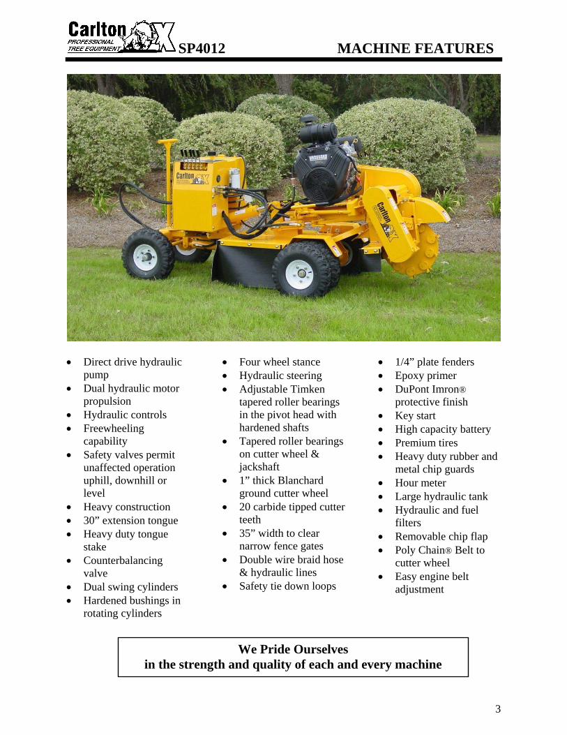
• Direct drive hydraulic
pump • Dual hydraulic motor
propulsion • Hydraulic controls • Freewheeling
capability • Safety valves permit
unaffected operation uphill, downhill or level
• Heavy construction • 30” extension tongue • Heavy duty tongue
stake • Counterbalancing
valve • Dual swing cylinders • Hardened bushings in
rotating cylinders
• Four wheel stance • Hydraulic steering • Adjustable Timken
tapered roller bearings in the pivot head with hardened shafts
• Tapered roller bearings on cutter wheel & jackshaft
• 1” thick Blanchard ground cutter wheel
• 20 carbide tipped cutter teeth
• 35” width to clear narrow fence gates
• Double wire braid hose & hydraulic lines
• Safety tie down loops
• 1/4” plate fenders • Epoxy primer • DuPont Imron®
protective finish • Key start • High capacity battery • Premium tires • Heavy duty rubber and
metal chip guards • Hour meter • Large hydraulic tank • Hydraulic and fuel
filters • Removable chip flap • Poly Chain® Belt to
cutter wheel • Easy engine belt
adjustment
We Pride Ourselves
in the strength and quality of each and every machine

SP4012 MACHINE SPECIFICATIONS
4
Engine...................................................Briggs & Stratton 35HP Vanguard Weight ..................................................1650 Lbs. Length...................................................8’ 6” Tongue Extension.................................30” Height ...................................................46” Width ....................................................35” Cutting Depth Below Ground ......................................13” Cutting Height Above Ground ......................................34” Cutter Head Swing ...............................40” Arc Number of Teeth on Cutter Wheel ...................................20 Cutter Wheel Diameter w/Teeth.................................21” Cutter Wheel Thickness .......................1” Blanchard Ground Jackshaft Bearings................................1 11/16” Cutter Wheel Bearings .........................1 11/16” Tire size ................................................8 ply 5.70-4 Fuel Tank Capacity ..............................10.3 Gallons Hydraulic Tank Capacity .....................3.6 Gallons

SP4012 SAFETY PRECAUTIONS
5
Before operating the stump cutter, read this manual, the engine manual, and all the safety decals on the machine. Know all parts of the machine and their functions, especially the shut down procedures in case of emergency. No inexperienced person may operate machine. Inexperience may cause injury. SAFETY FIRST ALWAYS! This is the Safety-Alert Symbol. This symbol is placed on the machine and in the manual to alert the operator to the potential for bodily injury or death. The operator should pay close attention to the instructions whenever they see this symbol. The Safety-Alert Symbol will be accompanied by one of the following words:
DANGER, WARNING, or CAUTION • A DANGER symbol means that if the instructions are not followed the possibility of
serious personal injury or death is probable. • A WARNING symbol means that if the instructions are not followed there is a
possibility of serious personal injury or death. • A CAUTION symbol means there is an unsafe condition or practice that may cause
personal injury or property damage. PERSONAL PROTECTION:
Wear face shield and hearing protection Do not wear loose-fitting
clothing Tie back long hair Do not wear jewelry Keep clear of cutter wheel Keep away from moving parts Only operate in a well ventilated
area because of carbon monoxide
P/N 0700008 P/N 0700010 P/N 0700027

SP4012 SAFETY PRECAUTIONS
6
Be Safe and Practice Safe Operation using the following guidelines.
• Any individual operating this machine must first read and understand this manual, the engine manual, all component manuals, and all safety decals on machine.
• DO NOT permit children to operate machinery or to play near machinery during operation.
• Always wear face shield and hearing protection during operation. Loud noise and flying debris may cause severe injury.
• Keep hands, feet, legs, clothing, hair and all other body parts away from cutter wheel and other moving machine parts to eliminate the possibility of injury.
• Shut down machine completely and remove key before removing debris from work area (i.e. clearing rocks, wood chips, etc.).
• DO NOT modify or change any part without written approval from J. P. Carlton Company.
• Do not ride, sit, stand, lay or climb anywhere on this machine during operation, while running, or during transport.
• Do not move, position, or transport this machine while cutter wheel is engaged.
• DO NOT operate any machinery while under the influence of alcohol or drugs (prescription, over the counter, or otherwise).
• Do not refill fuel tank while engine is hot, running, or indoors. Danger of fire or explosion exists.
• Fuel and its vapors are highly flammable and explosive. Handle with care. Only use approved (red) fuel containers for storage.
• Do not store fuel containers near any open flames, sparks or other sources of ignition.
• Do not store equipment with fuel in the tank. • Battery fumes are explosive. Recharge battery in an open
area away from fire, sparks, or other sources of ignition. • Battery acid can cause severe burns. Keep away from eyes,
skin, and clothing. • Always remove battery before welding on equipment.
• Never check for hydraulic leaks using hand or finger, use cardboard or wood. Keep away from pressurized leaks. Pressurized fluid can penetrate the skin and cause injury or even death. Seek immediate medical attention if penetration occurs. Always wear eye protection.
SP4012 SAFETY PRECAUTIONS
7
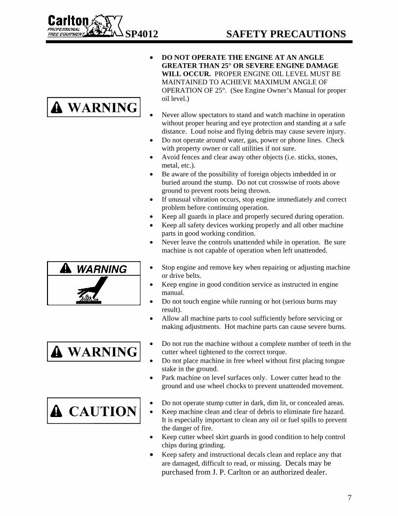
• DO NOT OPERATE THE ENGINE AT AN ANGLE
GREATER THAN 25° OR SEVERE ENGINE DAMAGE WILL OCCUR. PROPER ENGINE OIL LEVEL MUST BE MAINTAINED TO ACHIEVE MAXIMUM ANGLE OF OPERATION OF 25°. (See Engine Owner’s Manual for proper oil level.)
• Never allow spectators to stand and watch machine in operation
without proper hearing and eye protection and standing at a safe distance. Loud noise and flying debris may cause severe injury.
• Do not operate around water, gas, power or phone lines. Check with property owner or call utilities if not sure.
• Avoid fences and clear away other objects (i.e. sticks, stones, metal, etc.).
• Be aware of the possibility of foreign objects imbedded in or buried around the stump. Do not cut crosswise of roots above ground to prevent roots being thrown.
• If unusual vibration occurs, stop engine immediately and correct problem before continuing operation.
• Keep all guards in place and properly secured during operation. • Keep all safety devices working properly and all other machine
parts in good working condition. • Never leave the controls unattended while in operation. Be sure
machine is not capable of operation when left unattended. • Stop engine and remove key when repairing or adjusting machine
or drive belts. • Keep engine in good condition service as instructed in engine
manual. • Do not touch engine while running or hot (serious burns may
result). • Allow all machine parts to cool sufficiently before servicing or
making adjustments. Hot machine parts can cause severe burns. • Do not run the machine without a complete number of teeth in the
cutter wheel tightened to the correct torque. • Do not place machine in free wheel without first placing tongue
stake in the ground. • Park machine on level surfaces only. Lower cutter head to the
ground and use wheel chocks to prevent unattended movement. • Do not operate stump cutter in dark, dim lit, or concealed areas. • Keep machine clean and clear of debris to eliminate fire hazard.
It is especially important to clean any oil or fuel spills to prevent the danger of fire.
• Keep cutter wheel skirt guards in good condition to help control chips during grinding.
• Keep safety and instructional decals clean and replace any that are damaged, difficult to read, or missing. Decals may be purchased from J. P. Carlton or an authorized dealer.

SP4012 SAFETY PRECAUTIONS
8
ATTENTION: The Carlton® Model SP4012 Stump Grinder CAN be overturned on steep inclines. This can cause serious injury to operator and machine. DO NOT OVERTURN!
• Avoid steep side inclines when operating
this machine! The narrow design width required in operating the model SP4012 in tight confines makes it susceptible to tipping over sideways. Overturning this machine can result in personal injury, property damage and/or seizing the engine. USE CAUTION.
• Positioning the cutter wheel uphill and
as close to the ground as possible while in transit will minimize the danger of tipping over and maximize the steadiness of the Model SP4012.
• When encountering a hill, the best
approach is straight up or straight down. Avoid any side angles whenever possible. NEVER ALLOW INEXPERIENCED PERSONS TO OPERATE THIS MACHINE.
P/N 0700024

SP4012 DAILY CHECKLIST
9
• Check engine oil at dipstick. Take reading
with engine sitting level (see photos). Add recommended oil as required (see engine owners’ Manual).
• Check fuel filter for debris or water. • Replenish fuel tank with fresh fuel. • Check condition and tightness of engine belts.
(See Servicing Belts section) New belts will stretch and become loose as machine runs. Check belt tension often when belts are new.
• Check for any loose, broken or missing cutter teeth and pockets.
• Inspect bolts, hydraulic fittings, wiring harnesses, hoses and equipment for tightness, wear, or leakage. Replace if necessary.
• Inspect dry air filters. REPLACE, if necessary, WITH FACTORY AIR FILTER ONLY (see Maintenance Section for part numbers). Do not blow out or tap on ground. Follow engine manual procedure for removal and replacement. Because of the environment of a stump grinder, air filters need to be inspected and replaced more often than the engine manufacturer recommends.
• Replace inner safety filter when dirty or when the outer air filter has been changed 3 times. Do not blow out the inner safety filter or tap on ground. Do not allow dirt to get into engine when removing filters. Dirt ingestion will cause engine failure and is not warranted.
• Check hydraulic oil daily, with engine off and cool, and replenish as necessary. This Carlton stump grinder is equipped with a gauge that shows the level of oil and the temperature of the oil. When filling the tank with oil, the window of the gauge will also fill with oil, as the level gets higher in the tank. Never fill the oil tank above the BLACK line at the top of the gauge. Do not run the machine with the oil level below the RED line at the bottom of the gauge.
• Check condition of tires. Inflate to proper pressure.
• Grease cutter wheel and jackshaft bearings daily. Purge bearings until new grease is seen.
CORRECT POSITION
INCORRECT POSITION
OIL LEVEL/TEMP GAUGE

SP4012 MACHINE CONTROLS
10
ENGINE CONTROLS - Refer to engine manufacturers owners’ manual for controls, operation,
and service. • The Key Switch for starting the engine
is located on the Vanguard engine. There is also a choke lever and throttle lever on the engine. Read the engine manual for proper starting and operating instructions.
DO NOT OPERATE THE ENGINE AT AN ANGLE GREATER THAN 25° OR SEVERE ENGINE DAMAGE WILL OCCUR. PROPER ENGINE OIL LEVEL MUST BE MAINTAINED TO ACHIEVE MAXIMUM ANGLE OF OPERATION OF 25°. (See Engine Owner’s Manual for proper oil level.)
HYDRAULIC CONTROLS • A series of hydraulic controls are located
on the machine and are clearly marked.
STEERING TRAVEL - (lever 1) • Push or pull control lever to control
steering, right or left.
CHOKE
KEY SWITCH
THROTTLE

SP4012 MACHINE CONTROLS
11
UNIT TRAVEL - (lever 2) • Push or pull control lever to control
travel, forward or reverse. This lever controls the dual drive motors on the rear wheels.
The Cutter Head may be moved in any of three directions. CUTTER WHEEL (Lift) - (lever 3) (Shown as CUTTER HEAD –UP/DOWN on radio transmitter.) • This lever operates the cutter head lift
function, which raises and lowers the cutter head.
TONGUE - (lever 4) • This lever operates the tongue extension
function, which moves the machine toward the stump and pulls the machine back away from the stump.
BOOM TRAVEL (Swing) - (lever 5) (Shown as CUTTER HEAD –RIGHT/LEFT on radio transmitter.) • This lever operates the cutter head swing
function, which swings the boom back and forth in a left-right-left-right-left… motion.
SP4012 MACHINE CONTROLS
12
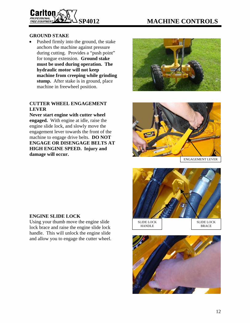
GROUND STAKE • Pushed firmly into the ground, the stake
anchors the machine against pressure during cutting. Provides a “push point” for tongue extension. Ground stake must be used during operation. The hydraulic motor will not keep machine from creeping while grinding stump. After stake is in ground, place machine in freewheel position.
CUTTER WHEEL ENGAGEMENT LEVER Never start engine with cutter wheel engaged. With engine at idle, raise the engine slide lock, and slowly move the engagement lever towards the front of the machine to engage drive belts. DO NOT ENGAGE OR DISENGAGE BELTS AT HIGH ENGINE SPEED. Injury and damage will occur. ENGINE SLIDE LOCK Using your thumb move the engine slide lock brace and raise the engine slide lock handle. This will unlock the engine slide and allow you to engage the cutter wheel.
ENGAGEMENT LEVER
SLIDE LOCK HANDLE
SLIDE LOCK BRACE

SP4012 MACHINE CONTROLS
13
GEAR SELECTOR • Push switch up to run machine at high gear and
push switch down to run machine at low gear. Machine has more climbing power in low gear. MUST BE IN HIGH GEAR TO CHANGE INTO FREEWHEEL.
FREEWHEELING VALVE • Releases wheels from the drive system by
overriding the hydraulics. To engage, push knob in and turn a quarter turn counter-clockwise. Tongue extension can be accomplished by setting the lever to freewheeling position. Always make sure that the ground stake is in the ground before placing machine in free wheel. To disengage freewheel, push knob in and turn clockwise back to original position. Knob will pop out when freewheeling is disengaged. FREEWHEEL WILL ONLY OPERATE WITH GEAR SELECTOR IN THE HIGH POSITION.
TRAVEL SPEED ADJUSTMENT • Adjust travel speed for smooth operation. Turn
valve counter-clockwise to decrease travel speed.
SWING SPEED ADJUSTMENT • Adjust swing speed for smooth operation. Turn
valve counter-clockwise to slow cutter head swing. Close valve by turning clockwise to allow head to move side to side at low RPM.
Gear Selector
Freewheeling Valve
Travel Speed Adjustment
Swing Speed Adjustment

SP4012 MACHINE CONTROLS
14
OPTIONAL 4-WHEEL DRIVE AND BLADE FUNCTIONS If a machine is ordered as a 4-wheel drive unit, it will come with drive motors on the front as well as the rear wheels. The 4-wheel drive unit can also be supplied with a Blade option. The following is the control operation information about these optional functions. STEERING TRAVEL - (lever 1) • Push or pull control lever to control
steering, right or left. The steering travel function will operate in the same manner but the machine will look slightly different, as shown in the picture to the right.
UNIT TRAVEL - (lever 2) • Push or pull control lever to control
travel, forward or reverse. This lever controls the four drive motors on the front and rear wheels.
BLADE - (lever 4) (Optional) • This lever operates the blade function,
which moves the scrape blade up and down. To backfill the hole after grinding the stump, lower the scrape blade by pulling the lever back. At all other times keep the scrape in the raised position.
FRONT DRIVE MOTORS

SP4012 MACHINE CONTROLS
15
OPTIONAL REMOTE CONTROL OPERATION – WIRED • The control functions operate the same
on a remote control machine as they do on a standard machine. Instead of having the machine mounted control levers as described earlier in this section, there are toggle switches on the machine control box and on the remote control unit. The toggle switches on the machine control panel can be used to operate the machine for short-term operation to position the machine or to test the operation of the functions.
• Use the switches on the remote transmitter to operate the machine when moving the machine to the job site and when grinding the stumps. For a remote control machine with a wired remote transmitter, turn the Machine ON/Remote ON switch to Remote On and turn the Engine switch on the transmitter to RUN. Now start the engine using the key switch, run the engine a few minutes to allow the oil to circulate before starting to operate the functions. After the engine has been running for a few minutes, test the remote transmitter by testing the functions for correct operation. After testing the functions and everything is operating correctly, proceed to the job site.
• Some functions require using the machine mounted controls, such as the Swing Speed Adjustment Valve, the Ground Speed Adjustment Valve, the Freewheel Valve on machines equipped with freewheel motion, and the Engagement Lever to engage the cutter wheel. The Swing Speed Adjustment, Freewheel, and Ground Speed Adjustment Valves are on opposite sides of the machine from the standard machine but still operate the same.
MACHINE ON / REMOTE ON SWITCH
REMOTE CONTROL MACHINE – TOGGLE SWITCHES
WIRED REMOTE TRANSMITTER WITH 25’ CORD
REMOTE TRANSMITTER
PLUG RECEIVER
SWING SPEED ADJUSTMENT
HIGH/LOW GEAR SWITCH
GROUND SPEED ADJUSTMENT
FREEWHEEL VALVE

SP4012 MACHINE CONTROLS
16
SAFETY
• NEVER SERVICE A MACHINE WITH THE ENGINE RUNNING, SEVERE PERSONAL INJURY COULD OCCUR. TURN ENGINE OFF THEN REMOVE IGNITION KEY AND DISCONNECT POSITIVE BATTERY CABLE TO AVOID STARTING MACHINE ACCIDENTALLY.
• CUTTER WHEEL MUST BE DISENGAGED BEFORE TURNING ENGINE ON/OFF AND BEFORE SERVICING A MACHINE. OTHERWISE SEVERE PERSONAL INJURY COULD OCCUR AS WELL AS MACHINE DAMAGE.
• ALL MACHINE PARTS MUST COME TO A COMPLETE STOP AND HAVE TIME TO COOL COMPLETELY BEFORE SERVICING A MACHINE OR SEVERE INJURY COULD OCCUR, POSSIBLY SERIOUS BURNS AND/OR DISMEMBERMENT.
• PLACE THE CUTTER WHEEL ON THE GROUND WHEN PERFORMING SERVICE ON A MACHINE.
OPTIONAL REMOTE CONTROL CONVERTING FROM WIRED TO RADIO TRANSMITTER • To change from a wired to a radio
(wireless) transmitter, remove the lower cover on the control box. There are 2 bolts on each side.
• You can now see the wired remote control receiver. Remove the receiver cover. Drill holes in this cover for attaching the radio control receiver; make sure the hole locations match the bolt locations on the radio receiver.
• Bolt the radio receiver to the cover and then replace the cover on the wired remote receiver inside the control box.
• Use the wiring and connector diagrams, in the radio control manual included at the back of this manual, to wire directly to the appropriate contacts of the machine electronics. Contact your Carlton dealer if you need assistance not the radio control manufacturer.
• The radio transmitter and receiver will be programmed at the factory when purchased as a set.
THE RADIO CONTROL RECEIVER, SHOWN AT THE RIGHT, MUST BE
INSTALLED IN THE CONTROL BOX
REMOVE THE CONTROL BOX BOTTOM COVER
REMOVE THE COVER ON THE REMOTE RECEIVER AND DRILL HOLES TO ATTACH THE RADIO RECEIVER

SP4012 MACHINE CONTROLS
17
OPERATION – WIRELESS • THE CUTTER WHEEL MUST BE
DISENGAGED BEFORE STARTING THE MACHINE.
• To start the engine and radio control transmitter, follow these instructions.
• On the machine, turn the ignition key switch to ON (see engine picture below right), the machine switch to Remote On, and make sure the Gear switch is in the HIGH position.
• On the transmitter, press the E-STOP button down.
• Toggle any switch on the transmitter. • Twist the E-STOP button clockwise to
release. Release the E-STOP button within 10 seconds to power up or the unit will power down. When the transmitter is operating there is a yellow light that will be flashing, the light is indicated in the picture at the right. (Read the radio control manual for more information on the meaning of different lights and colors.) If the transmitter doesn’t start, check the transmitter for stuck switches, it will not start with a switch in the ON position.
• Now start the engine using the key switch. If the engine doesn’t start right away and you have to restart it, make sure the light on the transmitter is still on, and restart the engine. If you lose the connection (light off), repeat the procedure from the beginning and perform each step exactly as described. Test controls for proper operation.
• The E-STOP button turns off the
transmitter and the machine when it is pressed down.
• When the Gear switch is toggled up to HIGH, it only operates when the Travel function is being used.
GEAR SWITCH - HIGH POSITION
PUSH SWITCH UP TO REMOTE ON
TOGGLE ANY SWITCH
E-STOP BUTTON A YELLOW LIGHT WILL BE FLASHING
WHEN TRANSMITTER IS SENDING SIGNALS
TO THE RECEIVER
LOW BATTERY / FAULT LIGHT
KEY SWITCH
NEVER WELD ON A MACHINE WITH RADIO CONTROLS WITHOUT FIRST DISCONNECTING THE RECEIVER WIRE HARNESS, OTHERWISE THE RADIO RECEIVER WILL BE DESTROYED.

SP4012 MACHINE CONTROLS
18
PROGRAMMING – WIRELESS • If there is a problem with the receiver or
the transmitter and either has to be replaced, you will need to program the new unit to communicate with the existing unit. Or if you have more than one transmitter for this machine, it will need to be programmed to communicate with the existing receiver.
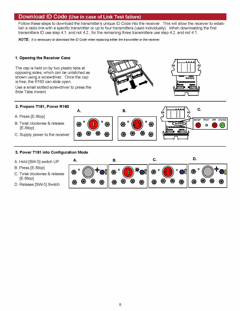
• To program the transmitter and receiver, you have to download the transmitter’s unique code into the receiver. There are complete instructions along with colored illustrations in the radio control manual included in the back of this manual.
• To access the receiver, remove the front cover from the machine control box.
• Remove the cover of the remote receiver
with the radio receiver attached. This will make it easier to work with the radio receiver. Remove the radio receiver panel by unlatching the plastic tabs on either side of the receiver; see the radio control manual in this manual in the back. The receiver panel will now slide out of the cap.
• Follow the instructions in the radio
control manual to download the ID Code. There are specific instructions that need to be followed and corresponding illustrations. The radio control manual is included in the back of this manual.
• Push the receiver panel back up into the cap until the tabs snap back into place.
• Always replace the machine cover when
maintenance or troubleshooting is complete. DO NOT RUN MACHINE WITHOUT ALL GUARDS & COVERS IN PLACE AND SECURED.
REMOVE THE REMOTE COVER TO ACCESS THE RADIO RECEIVER UNIT
REMOVE COVER
RELEASE THE RADIO RECEIVER CAP BY UNLATCHING THE TABS ON EACH SIDE

SP4012 MACHINE CONTROLS
19
TROUBLESHOOTING SEE THE RADIO CONTROL MANUAL FOR ANY OPERATING PROBLEMS WITH THE RADIO RECEIVER & TRANSMITTER (Included in the back of this manual) • First check the batteries to make sure
they are providing enough power to operate the transmitter.
• There is a low battery light on the transmitter, when it starts flashing you have approximately 10 hours of operation left.
• Remove the back cover on the transmitter. Remove old batteries and replace with new batteries. The transmitter operates using 4 AA alkaline batteries.
• Next, open the cover on the machine
control box. You will need to be able to see the lights on the receiver to compare to the trouble indicators on the receiver diagnostic list in the radio control manual. Check the light configuration and compare it to the Receiver Diagnostic list in the radio control manual.
• If status light on radio receiver is
flashing red, a fuse is blown. To change a fuse, remove the receiver panel from the cap and change the fuse. Inspect wiring for short circuits (e.g. bare wires). If problem re-occurs, call for service. Push the receiver panel back up into the cap until the tabs snap back into place.
• Always replace the machine cover when
maintenance or troubleshooting is complete. DO NOT RUN MACHINE WITHOUT ALL GUARDS & COVERS IN PLACE AND SECURED.
LOW BATTERY LIGHT
REMOVE THE BACK COVER TO ACCESS THE BATTERIES – THERE ARE 4 SCREWS HOLDING IT IN PLACE. THE BATTERY COMPARTMENT IS LABELED FOR CORRECT BATTERY ORIENTATION.
COMPARE THE LIGHT CONFIGURATION ON THE RECEIVER TO THE DIAGNOSTIC CHART IN THE RADIO
CONTROL MANUAL
REPLACE FUSE
REMOVE COVER

SP4012 TRANSPORTING
20
DO NOT TOW! THE MODEL SP4012 IS DESIGNED TO BE TRANSPORTED TO THE JOB SITE AND WILL MOVE UNDER ITS OWN POWER ONCE ON SITE. Transport machine in a suitable vehicle designed for a load of these dimensions and weight. A low trailer is recommended due to its decreased entry height, and will be safer all around. Always use safety tie down straps while transporting. The model SP4012 can be loaded into a pick-up truck, but requires increased safety precautions against tipping. Tie-downs, a sturdy and stable loading ramp and extra caution are required. • LOADING RAMPS MUST BE STURDY AND ATTACHED TO THE
TRANSPORT VEHICLE BEFORE ATTEMPTING TO LOAD\UNLOAD THIS MACHINE.
• TRAILER MUST BE SECURELY ATTACHED TO TOW VEHICLE
BEFORE LOADING OR UNLOADING THE STUMP GRINDER. • Check trailer for security and make
sure chains are properly installed. • Check tires inflation. • Check towing lights for proper
operation • Never transport with machine
motor running.
• Towing will affect handling. Allow for extra stopping distances.
• Start and stop gradually. • Tow at a safe reasonable speed.
Obey posted speed limits.

SP4012 TRANSPORTING
21
LOADING • TRAILER MUST BE SECURELY ATTACHED
TO TOW VEHICLE BEFORE LOADING OR UNLOADING THE STUMP GRINDER.
• DO NOT LOAD OR UNLOAD ON ANYTHING OTHER THAN LEVEL GROUND.
• Check valve to make sure machine is NOT in freewheeling mode. (See Machine Controls section for more information on freewheeling operation.)
• Start engine as recommended by the engine manufacturers manual.
• Increase engine RPM, and raise cutter head just off the ground.
• With operator in position, push the forward travel control lever and steer machine slowly up appropriate ramp into transport vehicle. KEEP MACHINE AS LEVEL AS POSSIBLE.
• Continually adjust cutter head height as you go, keeping the mass as low to the ground as possible.
• Once the machine is loaded, lower the cutter head, shut down engine and secure machine tightly with sufficient tie-downs to prevent any movement in transit.
UNLOADING • TRAILER MUST BE SECURELY ATTACHED TO TOW VEHICLE BEFORE
LOADING OR UNLOADING THE STUMP GRINDER. • DO NOT LOAD OR UNLOAD ON ANYTHING OTHER THAN LEVEL GROUND. • Freewheeling valve MUST be in “drive” position to avoid machine runaway on ramp. (See
Machine Controls section for more information on freewheeling operation.) • Undo tie down straps and check ramps for sturdiness and positioning. • Start engine as recommended by the engine manufacturers manual. • Increase engine RPM, and raise cutter head to just clear deck and/or ramp. • Continually adjust cutter head height as you go, keeping the mass as low to the ground as
possible. • Proceed to work site using extreme caution on hills or uneven terrain.

SP4012 MACHINE OPERATION
22
STARTING – READ ENGINE MANUFACTURERS OWNERS’ MANUAL BEFORE
STARTING. • Check all fluids before starting. • Belts must be disengaged before starting. • Inspect all connections, teeth, tires, etc. (see Daily Checklist). • Start engine at half speed and allow sufficient time for oil to circulate before proceeding.
(See Machine Control section for starting the machine with a remote or radio control transmitter.)
• Test controls for proper operation. • Avoid transverse slopes. Ascend/descend hills straight up and down. A hydraulic safety
valve prevents the machine from picking up speed downhill. This may also be used as a brake by decreasing engine speed.
• Hydraulic motor will not hold machine as a parking brake. Machine will creep. • DO NOT OPERATE THE ENGINE AT AN ANGLE GREATER THAN 25° OR
SEVERE ENGINE DAMAGE WILL OCCUR. PROPER ENGINE OIL LEVEL MUST BE MAINTAINED TO ACHIEVE MAXIMUM ANGLE OF OPERATION OF 25°. (See Engine Owner’s Manual for proper oil level.)
• DO NOT OPERATE AROUND WATER, GAS, POWER, OR PHONE LINES. IF IN DOUBT, CHECK BEFORE GRINDING.
• WEAR FACE SHIELD AND HEARING PROTECTION. • KEEP CLEAR OF CUTTER WHEEL AND MOVING MACHINE PARTS. • KEEP SPECTATORS AWAY. • Position machine at stump with cutter wheel
a slight distance away from stump. Do not engage cutter wheel when positioning machine near stump. Hitting the stump with cutter wheel running will break the Poly Chain® belt.
• Remove clip and position ground stake as
far into the earth as possible. Drive in with hammer if necessary.

SP4012 MACHINE OPERATION
23
• Reduce engine RPM to idle. • Raise cutter head clear of stump. • Engage cutter wheel belts by raising engine
slide lock and then slowly pushing engagement lever toward front of machine. When the cutter wheel is fully engaged the engine slide lock will be in a raised position.
• Increase engine RPM to full. • Test controls for proper operation, speed,
and unobstructed movement. • Cutter head swing speed should be adjusted
to a rate that will allow cutter wheel to pass through stump smoothly. If jerking, bouncing, or significant drops in engine speed occur, swing rate is to rapid and must be decreased.
• Swing speed should be determined and adjusted with the controls in the full open position.
• A counter-rotating valve is located within the hydraulic system to adjust this speed. Turning the handle counter-clockwise will open the bypass and slow swing action. Turning it clockwise will close the valve and increase swing rate.
ENGAGE CUTTER WHEEL
RAISE ENGINE SLIDE LOCK
ENGINE SLIDE LOCK RAISED
SWING SPEED ADJUSTMENT

SP4012 MACHINE OPERATION
24
• Lower spinning cutter wheel to stump and
make a few light passes at stump to get a feel for the cutting action.
• Gradually increase cutting action and work away at stump by swinging cutter wheel left-to-right-to-left through stump in a sideways motion. Smooth, effortless cutting lengthens machine life, minimizes downtime, and is more profitable in the long run.
• Continue cutting stump by adjusting cutter wheel progressively lower until stump is cut well below ground level.
• Raise cutter wheel and swing clear of stump
then extend tongue to position machine closer to stump for next series of passes. Lower cutter wheel and continue cutting.
• Continue in this manner until stump has been removed.
• Larger stumps may require repositioning machine to work at best advantages.
• Raise cutter wheel clear of stump and return
to center position. • Reduce engine speed to idle. DO NOT
TURN MOTOR OFF. Engine must be allowed to cool slowly at idle for 3 – 5 minutes to avoid damage.
• With engine speed at idle; disengage drive belts by slowly pushing the engagement lever back toward the cutter wheel. The engine slide will lock automatically when belt is disengaged.
• DO NOT DISENGAGE DRIVE BELTS AT A HIGH ENGINE SPEED. Damage to belts and machine will occur.
• Allow cutter wheel to come to a full stop before inspecting work area.
• Retract tongue extension; take machine out of freewheel control and pull the tongue stake out of the ground.
• Turn motor off.

SP4012 MACHINE MAINTENANCE
25
SAFETY
• NEVER SERVICE A MACHINE WITH THE ENGINE RUNNING, SEVERE PERSONAL INJURY COULD OCCUR. TURN ENGINE OFF THEN REMOVE IGNITION KEY AND DISCONNECT POSITIVE BATTERY CABLE TO AVOID STARTING MACHINE ACCIDENTALLY.
• CUTTER WHEEL MUST BE DISENGAGED BEFORE TURNING ENGINE ON/OFF AND BEFORE SERVICING A MACHINE. OTHERWISE SEVERE PERSONAL INJURY COULD OCCUR AS WELL AS MACHINE DAMAGE.
• ALL MACHINE PARTS MUST COME TO A COMPLETE STOP AND HAVE TIME TO COOL COMPLETELY BEFORE SERVICING A MACHINE OR SEVERE INJURY COULD OCCUR, POSSIBLY SERIOUS BURNS AND/OR DISMEMBERMENT.
• DO NOT OPERATE A MACHINE WITHOUT A COMPLETE NUMBER OF TEETH IN THE CUTTER WHEEL PROPERLY INSTALLED. EXCESSIVE MACHINE VIBRATION WILL OCCUR CAUSING PREMATURE BEARING FAILURE AND EQUIPMENT DAMAGE.
• PLACE THE CUTTER WHEEL ON THE GROUND WHEN PERFORMING SERVICE ON A MACHINE.
• Check engine oil at dipstick daily; take
reading with engine sitting level (see photos). Add recommended oil and change oil as required. (See engine owners’ manual.)
SP4012 Engine Filters
- 0200141 Oil Filter - 0200142 Fuel Filter - 0200102C Air - Main Filter - 0200102D Air - Safety Filter
INCORRECT POSITION
CORRECT POSITION

SP4012 MACHINE MAINTENANCE
26
• Check hydraulic oil level daily. This
Carlton stump grinder is equipped with a gauge that shows the level of oil and the temperature of the oil. When filling the tank with oil, the window of the gauge will also fill with oil, as the level gets higher in the tank. Never fill the oil tank above the BLACK line at the top of the gauge. Do not run the machine with the oil level below the RED line at the bottom of the gauge.
• The machine is equipped with Citgo AW32 hydraulic oil at the time of manufacture. Use the same or equivalent.
• For a new machine, change the hydraulic oil
filter when the stump grinder has been operating for 10 hours. Replace with the same type of in-tank filter element supplied originally, available through Carlton or Carlton dealers. From this point on, change the filter every 200 hours of operation.
• Change hydraulic oil every 500 hours of operation or at least once a year depending on use. Flush the hydraulic tank when changing the hydraulic oil. Replace oil if it has a burnt odor or if it is contaminated. Replace oil if the stump grinder has been stored for a long period of time (all winter).
• Drain the hydraulic tank using the drain plug located on the bottom of the tank. Dispose of used oil according to state regulations.
• Check setscrews in Jackshaft Bearings and
Cutter Wheel Bearings for tightness weekly.

SP4012 MACHINE MAINTENANCE
27
• Check cutter wheel, pockets, and teeth for
wear. If any repair is needed, see “Servicing Cutter Wheel” section for further instruction.
Always clean tip of grease gun fitting and grease fitting on machine before attaching hose to prevent dirt from being forced into machine parts. • Grease jackshaft bearings Daily. These
bearings should be purged using grease EVERYDAY. Purge till new grease comes out. Use Texaco® Starplex II grease. Always clean tip of grease gun fitting and grease fitting on machine before attaching hose to prevent dirt from being forced into machine parts.
• Grease cutter wheel bearings Daily. These
bearings should be purged using grease EVERYDAY. Purge till new grease comes out. Use Texaco® Starplex II grease. Always clean tip of grease gun fitting and grease fitting on machine before attaching hose to prevent dirt from being forced into machine parts.
• Grease engine slide assembly every 15 – 20
hours of operation with approximately 2 to 4 shots of Texaco® Starplex II grease. (Total of 6 grease fittings.) DO NOT OVER GREASE.
• Grease engagement lever every 15 – 20
hours of operation with approximately 2 to 4 shots of Texaco® Starplex II grease.
ENGAGEMENT LEVER
GREASE FITTINGS

SP4012 MACHINE MAINTENANCE
28
• Clean out Poly Chain® Guard by removing
bottom portion of guard weekly. Chip build up will wear Poly Chain® Belt.
• Grease boom pivot monthly, swing cutter
wheel to the right to access grease fitting. Use Texaco® Starplex II grease. DO NOT OVER GREASE.
• Grease bottom pivot bearings monthly. Use
Texaco® Starplex II grease. You cannot over grease this area all parts are heat-treated.
• Grease steering wheel pivots every 2-3
months. Use Texaco® Starplex II grease. DO NOT OVER GREASE.
• Extend the tongue and use a cloth covered
with grease to lightly coat the tongue extension every 6 months.
SP4012 LUBRICATION CHART
29
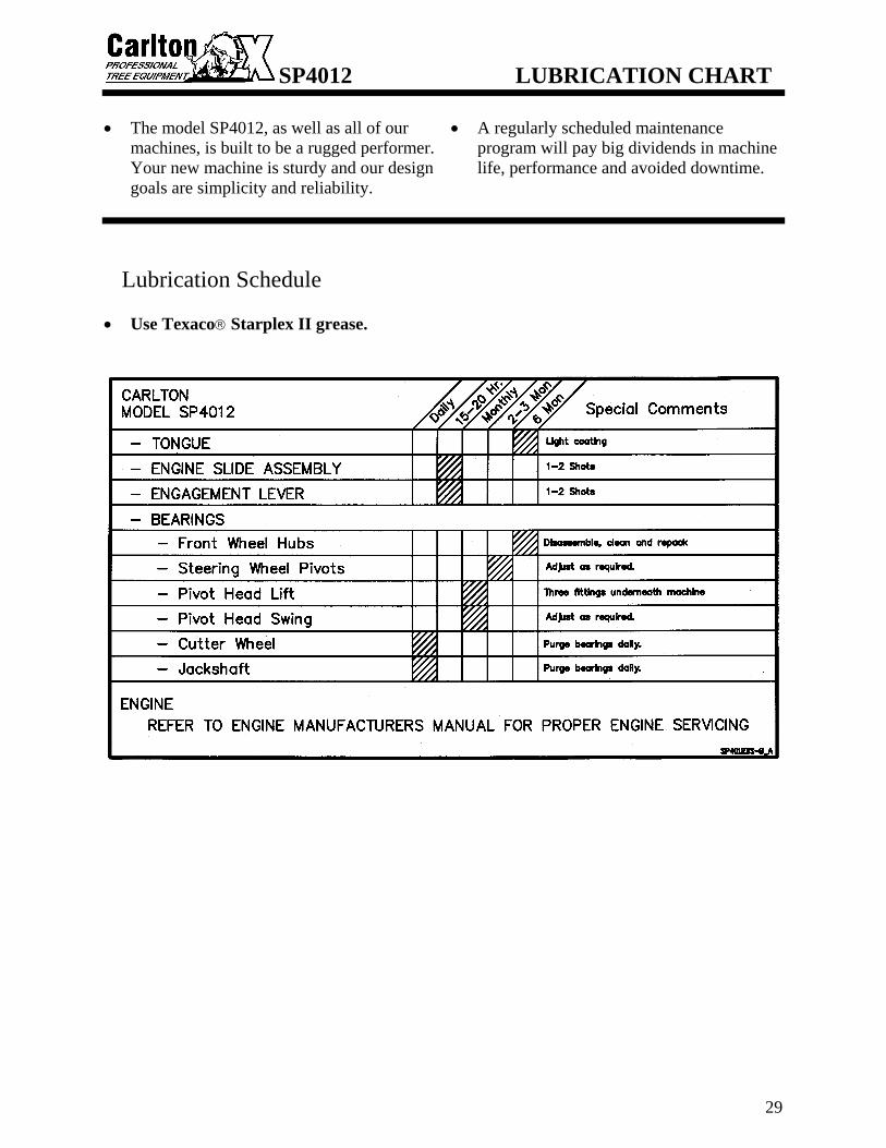
• The model SP4012, as well as all of our
machines, is built to be a rugged performer. Your new machine is sturdy and our design goals are simplicity and reliability.
• A regularly scheduled maintenance program will pay big dividends in machine life, performance and avoided downtime.
Lubrication Schedule • Use Texaco® Starplex II grease.

SP4012 TROUBLESHOOTING GUIDE
30
COMPLAINT CAUSE
CORRECTION
Engine will not start. (See Engine Manufacturer Manual for further information.)
• Loose ground wire. • Loose hot wire. • Dead battery.
• Clean and tighten. • Clean and tighten. • Recharge or replace.
Hydraulic system loss of power. • Low oil. • Valve set too low. • Missing or sheared
key on pump shaft. • Bad cylinder.
• Refill with correct oil. • Adjust relief valve. • Remove pump, replace or
repair keyway. • Replace cylinder packing.
Swing cylinder loss of power.
• Cutter head speed adjustment screw turned wide open.
• To slow cutter head swing at high RPM turn valve counter-clockwise.
• Re-adjust for “no bounce” cutting.
Belt Squeal.
• Belt tension too loose.
• Belt out of line.
• Tighten. • Align Pulleys.
Belt jumping off.
• Engaging or disengaging belt at high engine RPM.
• Belt keeper too far from belt.
• Only engage or disengage belts at low engine speeds.
• Adjust keeper closer to belt.
Cutter wheel vibration. • Tooth missing. • Pocket out of
balance. • Improper tooth
arrangement.
• Replace missing teeth. • Always replace pockets in
pairs across from each other.
• Install correctly with like pairs of teeth directly across from each other.
Cutter wheel throwing teeth.
• Bad pocket. • Dirt in pocket • Worn cutter wheel
• Replace pocket. • Clean pocket and replace
missing teeth. • Replace cutter wheel
Cutter wheel breaking teeth.
• Teeth set too far out of pocket.
• Use gauge to set teeth correctly.

SP4012 TROUBLESHOOTING GUIDE
31
COMPLAINT
CAUSE CORRECTION
Cutter wheel stops turning.
• Belt not engaged. • Engine belt broke. • Poly chain® belt broke. • Sheared key in shaft. • Broke cutter wheel shaft.
• Adjust yoke assembly. • Replace belt. • Replace belt. • Replace key. • Replace shaft.
Roar in machine when cutter wheel is engaged.
• Belt guards rubbing on jackshaft or cutter wheel shaft.
• Jackshaft or cutter wheel bearings going bad.
• Re-position guards off of shafts.
• Replace bearings.
Traction loss of power.
• Open free wheel valve. • Worn free wheel valve. • Relief valve set too low. • Hydraulic motor worn.
• Close free wheel valve. • Replace free wheel valve. • Increase relief valve
pressure by turning relief valve screw inward.
• Replace Hydraulic motor. Bearing will not take grease. • Grease fitting clogged. • Replace fitting Cutter head swings faster one way than the other.
• Counter balance valve is out of adjustment.
• Adjust counter balance valve to equalize swing speed.
For all Radio Transmitter or Receiver problems, see the Radio Control Manual included at the back of this manual.

SP4012 SERVICING BELTS
32
Replacing V-Belt SAFETY
• NEVER SERVICE A MACHINE WITH THE ENGINE RUNNING, SEVERE PERSONAL INJURY COULD OCCUR. TURN ENGINE OFF THEN REMOVE IGNITION KEY AND DISCONNECT POSITIVE BATTERY CABLE TO AVOID STARTING MACHINE ACCIDENTALLY.
• CUTTER WHEEL MUST BE DISENGAGED BEFORE TURNING ENGINE ON/OFF AND BEFORE SERVICING A MACHINE. OTHERWISE SEVERE PERSONAL INJURY COULD OCCUR AS WELL AS MACHINE DAMAGE.
• ALL MACHINE PARTS MUST COME TO A COMPLETE STOP AND HAVE TIME TO COOL COMPLETELY BEFORE SERVICING A MACHINE OR SEVERE INJURY COULD OCCUR, POSSIBLY SERIOUS BURNS AND/OR DISMEMBERMENT.
• DO NOT OPERATE A MACHINE WITHOUT A COMPLETE NUMBER OF TEETH IN THE CUTTER WHEEL PROPERLY INSTALLED. EXCESSIVE MACHINE VIBRATION WILL OCCUR CAUSING PREMATURE BEARING FAILURE AND EQUIPMENT DAMAGE.
• PLACE THE CUTTER WHEEL ON THE GROUND WHEN PERFORMING SERVICE ON A MACHINE.
• Remove V-belt guard cover, which is held on
with ten bolts. • Belt should be disengaged. If it isn’t, push
the engagement lever back toward the cutter wheel as far as it will go. Engine slide will lock automatically when the belt is disengaged. Belt will be loose when disengaged.
• Remove pump drive. Only remove the
bolts at 12 o’clock and 6 o’clock. Remove the pump plate with the pump still attached, not necessary to remove and cap hoses.

SP4012 SERVICING BELTS
33
Replacing V-Belt • When you pull the pump off, the pump
coupler and a rubber insert will come off with it. Take note of the insert and do not lose it.
• Loosen, don’t remove, all belt-keepers to
remove the engine belt. There are two belt keepers on the jackshaft sheave. The beehive has two belt keepers inside it, one on top and one on bottom. The last belt keeper is beside the beehive.
• Remove and replace the engine belt.
KEEP RUBBER INSERT TO PUT BACK INTO COUPLER
BELT KEEPERS

SP4012 SERVICING BELTS
34
Replacing V-Belt
• After replacing belt, check it for tension. • Engage belt using the engagement lever.
Raise the engine slide lock and push the engagement lever toward the front of the machine as far as it will go. Check belt tension. When the V-belt is tensioned properly, it will deflect 1/4” with 25 lbs. of force applied to the center of the belt between the sheaves. New belts will stretch and become loose as machine runs. Check belt tension often when belts are new.
• Disengage the belt. DO NOT START THE ENGINE. If any adjustment is required, there is a linkage assembly below the engagement handle on the operator side. Loosen jam nut and adjust clevis with wrench turning up toward machine. This will make engine slide further and will tighten the belt. Make only slight adjustments at a time and recheck tension; repeat as necessary until tension is correct. Once tightness is achieved, tighten jam nut back onto clevis.
• Use this same procedure to tighten loose belts.
• DO NOT OVER TIGHTEN BELTS; OVERLY TIGHT BELTS CAN CAUSE BEARING AND ENGINE DAMAGE. Turn the clevis down with a wrench if the belt is too tight. Make only slight adjustments at a time and recheck tension; repeat as necessary until tension is correct.
• Replace belts when worn or when repeated adjustments are necessary. Belts should never get so loose that all of the adjustment capability is used.
• Check to make sure the sheaves are still
aligned. Place a straight edge against both sheaves to check alignment. If the sheaves were not removed or loosened, they should still be aligned.
ENGAGE CUTTER WHEEL
JAM NUT CLEVIS
SP4012 SERVICING BELTS
35
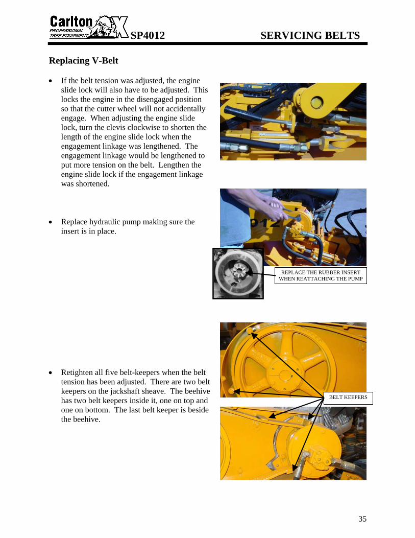
Replacing V-Belt • If the belt tension was adjusted, the engine
slide lock will also have to be adjusted. This locks the engine in the disengaged position so that the cutter wheel will not accidentally engage. When adjusting the engine slide lock, turn the clevis clockwise to shorten the length of the engine slide lock when the engagement linkage was lengthened. The engagement linkage would be lengthened to put more tension on the belt. Lengthen the engine slide lock if the engagement linkage was shortened.
• Replace hydraulic pump making sure the
insert is in place. • Retighten all five belt-keepers when the belt
tension has been adjusted. There are two belt keepers on the jackshaft sheave. The beehive has two belt keepers inside it, one on top and one on bottom. The last belt keeper is beside the beehive.
REPLACE THE RUBBER INSERT WHEN REATTACHING THE PUMP
BELT KEEPERS

SP4012 SERVICING BELTS
36
Replacing V-Belt • Replace V-belt guard cover and tighten bolts.
DO NOT RUN MACHINE WITHOUT ALL GUARDS IN PLACE AND SECURED.
GENERAL TENSIONING OF V-BELT DRIVES
Tensioning of belts on the V-belt drive is critical. A few simple rules about tensioning will satisfy most of your requirements: 1. The best tension for the V-belt drive is the
lowest tension at which the belts will not slip under the highest load condition.
2. Check the tension on a new drive frequently during the first day of operation.
3. Thereafter, check the drive belt tension periodically.
4. Too much tension shortens belt and bearing life.
5. Keep belts and sheaves free from any foreign material that may cause slippage.

SP4012 SERVICING BELTS
37
Replacing Poly Chain® Belt SAFETY
• NEVER SERVICE A MACHINE WITH THE ENGINE RUNNING, SEVERE PERSONAL INJURY COULD OCCUR. TURN ENGINE OFF THEN REMOVE IGNITION KEY AND DISCONNECT POSITIVE BATTERY CABLE TO AVOID STARTING MACHINE ACCIDENTALLY.
• CUTTER WHEEL MUST BE DISENGAGED BEFORE TURNING ENGINE ON/OFF AND BEFORE SERVICING A MACHINE. OTHERWISE SEVERE PERSONAL INJURY COULD OCCUR AS WELL AS MACHINE DAMAGE.
• ALL MACHINE PARTS MUST COME TO A COMPLETE STOP AND HAVE TIME TO COOL COMPLETELY BEFORE SERVICING A MACHINE OR SEVERE INJURY COULD OCCUR, POSSIBLY SERIOUS BURNS AND/OR DISMEMBERMENT.
• DO NOT OPERATE A MACHINE WITHOUT A COMPLETE NUMBER OF TEETH IN THE CUTTER WHEEL PROPERLY INSTALLED. EXCESSIVE MACHINE VIBRATION WILL OCCUR CAUSING PREMATURE BEARING FAILURE AND EQUIPMENT DAMAGE.
• PLACE THE CUTTER WHEEL ON THE GROUND WHEN PERFORMING SERVICE ON A MACHINE.
Special care needs to be taken with your Poly Chain® belt. Alignment, tension, and cleanliness of this belt are very important. The Poly Chain® belt needs to be checked for tension approximately every 70 to 100 hours of use. The Poly Chain® belt must be running true. If you adjust one bearing more than the other, the belt will run on an angle and will cause belt failure. A belt broken straight across is the result of a shock load. In a shock load failure, the fibers are broken and over a period of time the belt will break down from the shock load and snap in half. A broken belt with lost teeth indicates that the belt was loose. After you have installed or re-tensioned the Poly Chain® belt, you will have to re-adjust the engine V-belts for proper tension. • Remove the Poly Chain® guard cover and
bottom cover.

SP4012 SERVICING BELTS
38
Replacing Poly Chain® Belt • Loosen Poly Chain® belt by moving
jackshaft bearings. MARK THE BEARINGS SO THAT YOU KNOW HOW THEY ARE POSITIONED ON THE JACKSHAFT PLATE. Loosen bolts on bearing closest to Poly Chain® guard and remove bolts on the bearing closest to engine belt guard so that side of the jackshaft may be raised to remove Poly Chain® belt.
• Loosen the jam bolts in the back and move
the bearings back. • Belt should be disengaged. If it isn’t push
the engagement lever back toward the cutter wheel as far as it will go. Engine slide should lock automatically when the belt is disengaged; check to make sure it does. (See Machine Controls section for engine slide lock.)
• Remove old belt and replace with new one.
Do not pry new belt over sprockets since this can break the fibers in the Poly Chain® belt.

SP4012 SERVICING BELTS
39
Replacing Poly Chain® Belt • Check alignment of Poly Chain® sprockets
using a straight edge. • To adjust tension of the belt, slide the
bearings back into the place that you had marked. Tighten the jam bolts. To tighten the belts more if needed, loosen the front jam bolts and tighten each of the back jam bolts the same number of revolutions, to keep the alignment true. After the belt is adjusted, tighten the front jam bolts back against the bearing. After the Poly Chain® belt has been adjusted; check the V-belt tension and alignment. When the V-belt is tensioned properly, it will deflect 1/4” with 25 lbs. of force applied.
• Replace Poly Chain® belt guard cover and
bottom cover and tighten bolts. DO NOT RUN MACHINE WITHOUT ALL GUARDS IN PLACE AND SECURED.

SP4012 SERVICING BELTS
40
Replacing Poly Chain® Belt

SP4012 SERVICING BEARINGS
41
Replacing Jackshaft Bearings SAFETY
• NEVER SERVICE A MACHINE WITH THE ENGINE RUNNING, SEVERE PERSONAL INJURY COULD OCCUR. TURN ENGINE OFF THEN REMOVE IGNITION KEY AND DISCONNECT POSITIVE BATTERY CABLE TO AVOID STARTING MACHINE ACCIDENTALLY.
• CUTTER WHEEL MUST BE DISENGAGED BEFORE TURNING ENGINE ON/OFF AND BEFORE SERVICING A MACHINE. OTHERWISE SEVERE PERSONAL INJURY COULD OCCUR AS WELL AS MACHINE DAMAGE.
• ALL MACHINE PARTS MUST COME TO A COMPLETE STOP AND HAVE TIME TO COOL COMPLETELY BEFORE SERVICING A MACHINE OR SEVERE INJURY COULD OCCUR, POSSIBLY SERIOUS BURNS AND/OR DISMEMBERMENT.
• DO NOT OPERATE A MACHINE WITHOUT A COMPLETE NUMBER OF TEETH IN THE CUTTER WHEEL PROPERLY INSTALLED. EXCESSIVE MACHINE VIBRATION WILL OCCUR CAUSING PREMATURE BEARING FAILURE AND EQUIPMENT DAMAGE.
• PLACE THE CUTTER WHEEL ON THE GROUND WHEN PERFORMING SERVICE ON A MACHINE.
In all Carlton® model Stump Grinders, you will find link belt bearings that are made to be purged with grease. It is necessary to purge these bearings everyday till clean grease is seen. CAUTION should be taken not to allow grease to build up inside the belt guards. • Remove the V-belt guard cover. • Remove engine belts and jackshaft pulley.
(See Servicing Belt section to remove engine belts.) To remove the jackshaft pulley, remove the bolts from the bushing and use them to screw into the empty threaded holes to push the bushing out of the pulley. Tighten each screw just a little and go on to the next screw keep tightening a little at a time until the bushing and pulley are separated.
AFTER REMOVING BOLTS, SCREW BOLTS
INTO THE THREADED HOLES TO PUSH THE BUSHING OUT OF THE PULLEY

SP4012 SERVICING BEARINGS
42
Replacing Jackshaft Bearings • Remove Poly Chain® belt guard cover and
bottom cover. • Remove Poly Chain® sprocket by removing
the bolts inside the sprocket and tapered bushing. Then screw one bolt into third hole to push sprocket off tapered bushing to remove.
• You may cut the jackshaft between the
bearings and the Poly Chain® guard. • Remove old bearings and shaft and replace
with new bearings and shaft. Be sure to turn jackshaft with the longest keyway pocket toward the Poly Chain® belt side of the boom and make sure that the locking collars on the bearings are facing inward. Bolt new bearings and jackshaft back into place. Just snug bolts down, do not tighten all the way down, you will need to move them later to adjust belt tension.

SP4012 SERVICING BEARINGS
43
Replacing Jackshaft Bearings NOTE: To make shaft installation easier, place shaft in a freezer for approximately one hour or overnight if possible. This will shrink the shaft and make installation into the new bearings much easier. • Place Poly Chain® sprocket and tapered
bushing back onto jackshaft and tighten bolts. Replace Poly Chain® belt. Alignment is very important, use a straight edge from the jackshaft sprocket down to the cutter wheel sprocket to line up sprockets.
• After replacing the jackshaft pulley and
bushing, use a straight edge and align the jackshaft pulley with the engine pulley. Tighten the three bushing bolts down. As you tighten the bushing bolts, make sure that the pulleys stay aligned.
• There are two setscrews in each bearing.
Tighten one of them down, remove one, and punch a start point in the shaft to drill a 5/16” diameter hole just deep enough for the screw to enter the shaft. Do this for all four setscrews. This will help prevent shaft from spinning inside of bearing. When replacing setscrews in bearings, use LocTite® 242 to prevent screws from loosening up.

SP4012 SERVICING BEARINGS
44
Replacing Jackshaft Bearings NOTE: Refer to SERVICING BELTS section for proper installation and tensioning of all belts. • Replace V-belt guard cover and tighten bolts. • Replace Poly Chain® belt guard cover and
end guard cover and tighten bolts.
DO NOT RUN MACHINE WITHOUT ALL GUARDS IN PLACE AND SECURED PROPERLY.

SP4012 SERVICING BEARINGS
45
Replacing Cutter Wheel Bearings SAFETY
• NEVER SERVICE A MACHINE WITH THE ENGINE RUNNING, SEVERE PERSONAL INJURY COULD OCCUR. TURN ENGINE OFF THEN REMOVE IGNITION KEY AND DISCONNECT POSITIVE BATTERY CABLE TO AVOID STARTING MACHINE ACCIDENTALLY.
• CUTTER WHEEL MUST BE DISENGAGED BEFORE TURNING ENGINE ON/OFF AND BEFORE SERVICING A MACHINE. OTHERWISE SEVERE PERSONAL INJURY COULD OCCUR AS WELL AS MACHINE DAMAGE.
• ALL MACHINE PARTS MUST COME TO A COMPLETE STOP AND HAVE TIME TO COOL COMPLETELY BEFORE SERVICING A MACHINE OR SEVERE INJURY COULD OCCUR, POSSIBLY SERIOUS BURNS AND/OR DISMEMBERMENT.
• DO NOT OPERATE A MACHINE WITHOUT A COMPLETE NUMBER OF TEETH IN THE CUTTER WHEEL PROPERLY INSTALLED. EXCESSIVE MACHINE VIBRATION WILL OCCUR CAUSING PREMATURE BEARING FAILURE AND EQUIPMENT DAMAGE.
• PLACE THE CUTTER WHEEL ON THE GROUND WHEN PERFORMING SERVICE ON A MACHINE.
In all Carlton® model Stump Grinders, you will find link belt bearings that are made to be purged. It is necessary to purge these bearing everyday until clean grease is seen. CAUTION should be taken not to allow grease to build up inside the belt guards. • Remove the Poly Chain® guard cover and
bottom cover. • Loosen Poly Chain® belt by moving
jackshaft bearings. MARK THEM SO THAT YOU KNOW HOW THEY ARE POSITIONED ON THE JACKSHAFT PLATE. Loosen the four bolts that hold the jackshaft bearings down, do not remove the bolts.

SP4012 SERVICING BEARINGS
46
Replacing Cutter Wheel Bearings • Loosen jam bolts in the back of the jackshaft
bearings and move bearings back to remove the Poly Chain® belt. You may need to unbolt V-belt guard and lift jackshaft end up to remove belt.
• Remove the four bolts on the cutter wheel
bearings. Cutter wheel will be free from machine at this point. With the Poly Chain® belt removed, you can start the machine and raise the boom up.
• Cut the cutter wheel shaft on one side of the
cutter wheel so that you can get the cutter wheel off of the shaft.
• Remove Poly Chain® sprocket by removing
the bolts inside the sprocket and tapered bushing. Then screw one bolt into third hole to push sprocket off tapered bushing to remove.

SP4012 SERVICING BEARINGS
47
Replacing Cutter Wheel Bearings • Take out the three bolts that hold the bushing
to the cutter wheel and place them in the empty threaded holes on the bushing and tighten slowly. This will push the bushing out of the cutter wheel. Remove bushing and cutter wheel.
• Place cutter wheel, bushing and bearings
back on new shaft. Place back up under machine and lower boom box on to bearings.
NOTE: To make shaft installation easier, place shaft in a freezer for approximately one hour or overnight if possible. This will shrink the shaft and make installation into the new bearings much easier. • Bolt bearings and cutter wheel back to boom
box and tighten bolts down.
SP4012 SERVICING BEARINGS
48
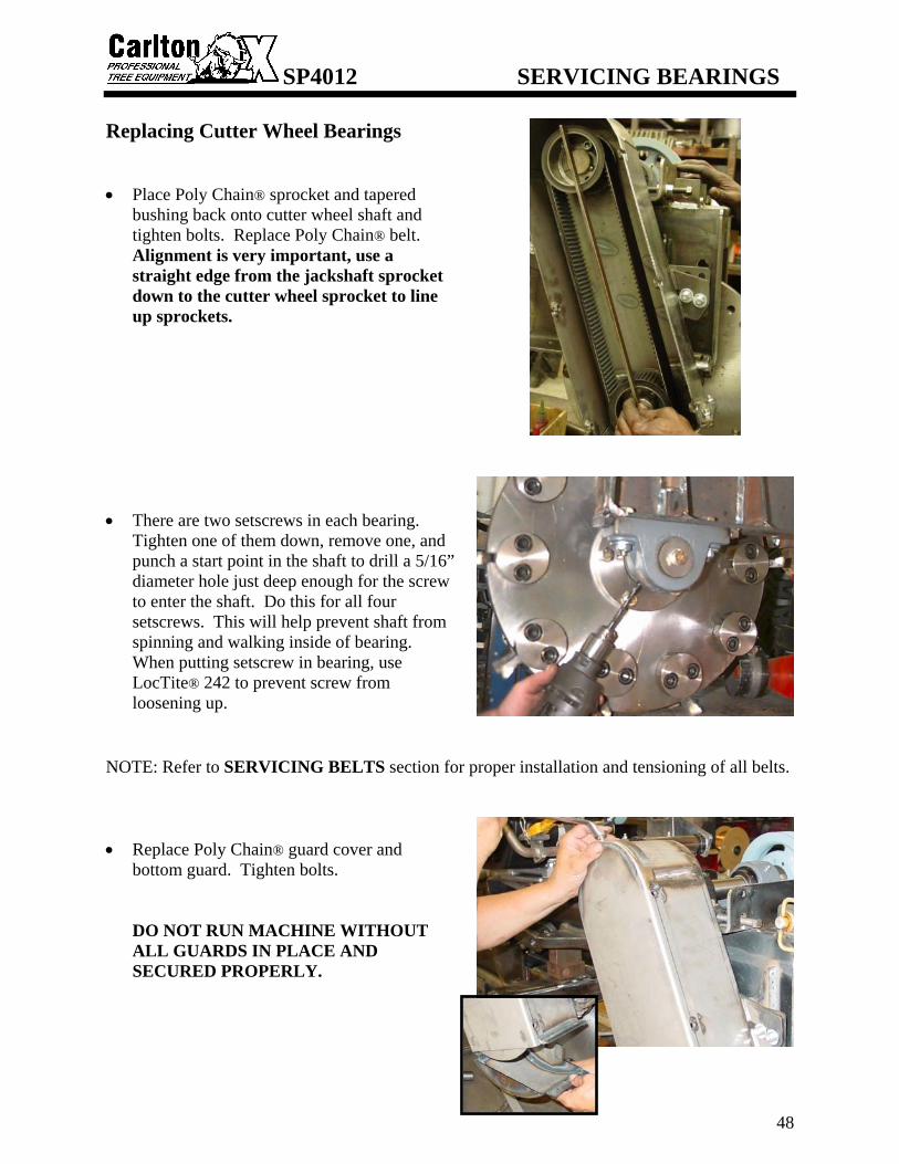
Replacing Cutter Wheel Bearings • Place Poly Chain® sprocket and tapered
bushing back onto cutter wheel shaft and tighten bolts. Replace Poly Chain® belt. Alignment is very important, use a straight edge from the jackshaft sprocket down to the cutter wheel sprocket to line up sprockets.
• There are two setscrews in each bearing.
Tighten one of them down, remove one, and punch a start point in the shaft to drill a 5/16” diameter hole just deep enough for the screw to enter the shaft. Do this for all four setscrews. This will help prevent shaft from spinning and walking inside of bearing. When putting setscrew in bearing, use LocTite® 242 to prevent screw from loosening up.
NOTE: Refer to SERVICING BELTS section for proper installation and tensioning of all belts. • Replace Poly Chain® guard cover and
bottom guard. Tighten bolts.
DO NOT RUN MACHINE WITHOUT ALL GUARDS IN PLACE AND SECURED PROPERLY.

SP4012 SERVICING FRONT AXLE
49
SAFETY
• NEVER SERVICE A MACHINE WITH THE ENGINE RUNNING, SEVERE PERSONAL INJURY COULD OCCUR. TURN ENGINE OFF THEN REMOVE IGNITION KEY AND DISCONNECT POSITIVE BATTERY CABLE TO AVOID STARTING MACHINE ACCIDENTALLY.
• CUTTER WHEEL MUST BE DISENGAGED BEFORE TURNING ENGINE ON/OFF AND BEFORE SERVICING A MACHINE. OTHERWISE SEVERE PERSONAL INJURY COULD OCCUR AS WELL AS MACHINE DAMAGE.
• ALL MACHINE PARTS MUST COME TO A COMPLETE STOP AND HAVE TIME TO COOL COMPLETELY BEFORE SERVICING A MACHINE OR SEVERE INJURY COULD OCCUR, POSSIBLY SERIOUS BURNS AND/OR DISMEMBERMENT.
• DO NOT OPERATE A MACHINE WITHOUT A COMPLETE NUMBER OF TEETH IN THE CUTTER WHEEL PROPERLY INSTALLED. EXCESSIVE MACHINE VIBRATION WILL OCCUR CAUSING PREMATURE BEARING FAILURE AND EQUIPMENT DAMAGE.
• PLACE THE CUTTER WHEEL ON THE GROUND WHEN PERFORMING SERVICE ON A MACHINE.
• Grease steering pivots at least every 2-3
months. Use Texaco® Starplex II grease. DO NOT OVER GREASE.
The steering axle is equipped with industrial hubs. To service, jack up the front end, remove cap. Loosen nut and slide wheel off. You are then able to inspect back seals, bearings and races. If necessary you may re-grease and install back on spindle. Tighten axle nut till bearing is tight and wheel will hardly turn. Then back off one notch. Do this at least every 6 months. (See Front Axle Assembly for breakdown)
SP4012 SERVICING BOOM PIVOT
50
SAFETY
• NEVER SERVICE A MACHINE WITH THE ENGINE RUNNING, SEVERE PERSONAL INJURY COULD OCCUR. TURN ENGINE OFF THEN REMOVE IGNITION KEY AND DISCONNECT POSITIVE BATTERY CABLE TO AVOID STARTING MACHINE ACCIDENTALLY.
• CUTTER WHEEL MUST BE DISENGAGED BEFORE TURNING ENGINE ON/OFF AND BEFORE SERVICING A MACHINE. OTHERWISE SEVERE PERSONAL INJURY COULD OCCUR AS WELL AS MACHINE DAMAGE.
• ALL MACHINE PARTS MUST COME TO A COMPLETE STOP AND HAVE TIME TO COOL COMPLETELY BEFORE SERVICING A MACHINE OR SEVERE INJURY COULD OCCUR, POSSIBLY SERIOUS BURNS AND/OR DISMEMBERMENT.
• PLACE THE CUTTER WHEEL ON THE GROUND WHEN PERFORMING SERVICE ON A MACHINE.
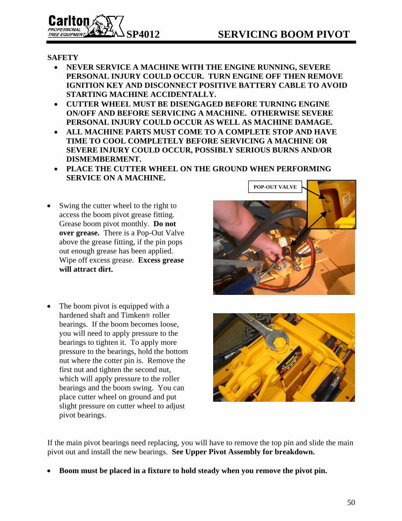
• Swing the cutter wheel to the right to
access the boom pivot grease fitting. Grease boom pivot monthly. Do not over grease. There is a Pop-Out Valve above the grease fitting, if the pin pops out enough grease has been applied. Wipe off excess grease. Excess grease will attract dirt.
• The boom pivot is equipped with a
hardened shaft and Timken® roller bearings. If the boom becomes loose, you will need to apply pressure to the bearings to tighten it. To apply more pressure to the bearings, hold the bottom nut where the cotter pin is. Remove the first nut and tighten the second nut, which will apply pressure to the roller bearings and the boom swing. You can place cutter wheel on ground and put slight pressure on cutter wheel to adjust pivot bearings.
If the main pivot bearings need replacing, you will have to remove the top pin and slide the main pivot out and install the new bearings. See Upper Pivot Assembly for breakdown. • Boom must be placed in a fixture to hold steady when you remove the pivot pin.
POP-OUT VALVE

SP4012 SERVICING CUTTER WHEEL
51
SAFETY
• NEVER SERVICE A MACHINE WITH THE ENGINE RUNNING, SEVERE PERSONAL INJURY COULD OCCUR. TURN ENGINE OFF THEN REMOVE IGNITION KEY AND DISCONNECT POSITIVE BATTERY CABLE TO AVOID STARTING MACHINE ACCIDENTALLY.
• CUTTER WHEEL MUST BE DISENGAGED BEFORE TURNING ENGINE ON/OFF AND BEFORE SERVICING A MACHINE. OTHERWISE SEVERE PERSONAL INJURY COULD OCCUR AS WELL AS MACHINE DAMAGE.
• ALL MACHINE PARTS MUST COME TO A COMPLETE STOP AND HAVE TIME TO COOL COMPLETELY BEFORE SERVICING A MACHINE OR SEVERE INJURY COULD OCCUR, POSSIBLY SERIOUS BURNS AND/OR DISMEMBERMENT.
• DO NOT OPERATE A MACHINE WITHOUT A COMPLETE NUMBER OF TEETH IN THE CUTTER WHEEL PROPERLY INSTALLED. EXCESSIVE MACHINE VIBRATION WILL OCCUR CAUSING PREMATURE BEARING FAILURE AND EQUIPMENT DAMAGE.
• PLACE THE CUTTER WHEEL ON THE GROUND WHEN PERFORMING SERVICE ON A MACHINE.
• There are twenty (20) teeth to a complete set
on the model SP4012. Two (2) straight teeth, nine (9) left 45° teeth and nine (9) right 45° teeth.
• A locking pin is provided to hold cutter
wheel in position during tooth removal and re-installation. Locking pin will only lock on outer teeth. NEVER PLACE HAND ON CUTTER WHEEL TO HOLD IN PLACE WHILE CHANGING TEETH. BE SURE TO REMOVE PIN BEFORE OPERATING.
• A Tooth Setting Gauge (P/N 0450111) is
provided with each machine for proper tooth installation. Line all teeth up with the inside edge of the groove in the gauge. Set ALL teeth to this edge with gauge against pocket, not against cutter wheel. See Cutter Wheel Assembly for breakdown.

SP4012 SERVICING CUTTER WHEEL
52
TOOTH ARRANGEMENT • Inspect pockets, teeth and bolts for damage
and replace as required. • When replacing pockets, always replace
new pockets across from each other in order to prevent vibration.
• Replacement teeth must be carbide tipped and have like design as provided with the machine.
• Use anti-seize on threads to prevent bolts from “freezing up” in cutter wheel.
• When replacing complete set of teeth, be sure to duplicate original factory tooth arrangement.
• Torque bolts to 150 ft/lbs.
opposing outside pockets carry like arrangements of teeth to cancel vibration • Straight teeth are mounted in TWO
OPPOSING OUTSIDE POCKETS. A straight tooth must have a 45° tooth accompanying it in the same pocket set.
• The opposite pocket sets should have this same combination of straight and 45° teeth, except with positions reversed. Mounting these teeth opposite each other on the cutter wheel cancels damaging vibration.
• Two Remaining Outside Pockets must have 45° teeth overlapping centerline of wheel to make plunge cuts possible. Mount two left 45° teeth opposite two right 45° teeth.
• Inside pockets require 45° teeth mounted away from the wheel.
SP4012 SERVICING CUTTER WHEEL
53
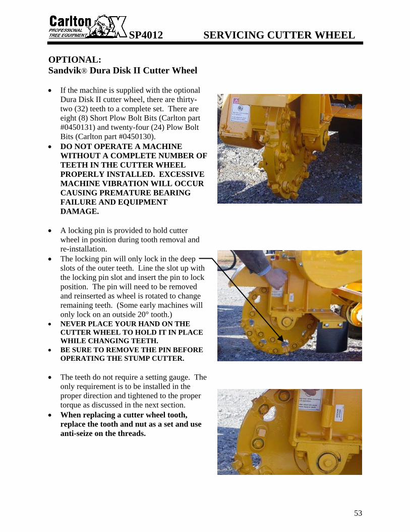
OPTIONAL: Sandvik® Dura Disk II Cutter Wheel • If the machine is supplied with the optional
Dura Disk II cutter wheel, there are thirty-two (32) teeth to a complete set. There are eight (8) Short Plow Bolt Bits (Carlton part #0450131) and twenty-four (24) Plow Bolt Bits (Carlton part #0450130).
• DO NOT OPERATE A MACHINE WITHOUT A COMPLETE NUMBER OF TEETH IN THE CUTTER WHEEL PROPERLY INSTALLED. EXCESSIVE MACHINE VIBRATION WILL OCCUR CAUSING PREMATURE BEARING FAILURE AND EQUIPMENT DAMAGE.
• A locking pin is provided to hold cutter
wheel in position during tooth removal and re-installation.
• The locking pin will only lock in the deep slots of the outer teeth. Line the slot up with the locking pin slot and insert the pin to lock position. The pin will need to be removed and reinserted as wheel is rotated to change remaining teeth. (Some early machines will only lock on an outside 20° tooth.)
• NEVER PLACE YOUR HAND ON THE CUTTER WHEEL TO HOLD IT IN PLACE WHILE CHANGING TEETH.
• BE SURE TO REMOVE THE PIN BEFORE OPERATING THE STUMP CUTTER.
• The teeth do not require a setting gauge. The
only requirement is to be installed in the proper direction and tightened to the proper torque as discussed in the next section.
• When replacing a cutter wheel tooth, replace the tooth and nut as a set and use anti-seize on the threads.

SP4012 SERVICING CUTTER WHEEL
54
TOOTH ARRANGEMENT • Inspect pockets, teeth and bolts for damage and
replace as required. • When replacing a cutter wheel tooth, replace
the tooth and nut as a set and use anti-seize on the threads.
• When replacing teeth and pockets, also replace the teeth and pockets across from each other diagonally in order to maintain wheel balance and prevent vibration.
• All teeth and pockets are of a specific design and must be replaced with original manufacturer’s replacement parts. Replacement teeth must be carbide tipped.
• When replacing complete set of teeth, be sure to duplicate original factory tooth arrangement. SEE DIAGRAM BELOW.
• The seating surfaces of the tooth and pocket are formed, but make sure the tooth is inserted with the carbide facing the direction of rotation.
• The pictured view is the engraved side of the wheel. The wheel is engraved with outside pocket numbers, outside pocket angle/direction (20 R or 20 L), and wheel rotation. (The engraved side of wheel is marked left side of wheel; this is for manufacturing purposes only. It does not refer to the left side of the machine as described in the General Information section.)
• Outside pocket teeth are Short Plow Bolt Bits. These pockets are angled and welded in place. You can switch teeth from one outside pocket to a pocket that is the opposite direction to prolong tooth life, such as switching a tooth from a 20 R with a tooth from a 20 L pocket. The cutting edge is the corner and this will turn the opposite corner out for use.
• These teeth are tightened with Stover Lock Nuts. Torque on Stover locking nuts is not to exceed 270 ft/lbs.
• All teeth on cutter wheel sides are Plow Bolt Bits. When changing these teeth you must remove both teeth in the same pocket, one on each side of the wheel. When the nuts are torqued, the pocket is jammed and the teeth can only be removed this way.
• These teeth are also tightened with Stover Lock Nuts. Torque on Stover locking nuts is not to exceed 270 ft/lbs.
• The pocket will receive wear when cutting and can be switched from one side of the cutter wheel to the other to prolong life. Remember the teeth must be replaced in the original position on each side of the wheel.
It may be necessary to use a 1 1/4” hole saw to remove debris around nut to make tooth removal easier.

SP4012 SERVICING CUTTER WHEEL
55
TOOTH SHARPENING
Begin by chamfering shank back past edge of carbide. You do this because if it is not back far enough the shank will hit the stump and not the carbide, thus causing a lot of vibration. Once the shank is angled far enough back, then begin sharpening carbide.
• Cut shank with a standard rock and cut carbide with a silicone carbide or
diamond rock. CAUTION: GRINDING CARBIDE CAN BE A HEALTH HAZARD. Use facemask to prevent breathing in harmful material while grinding.

SP4012 SERVICING HYDRAULICS
56
SAFETY
• NEVER SERVICE A MACHINE WITH THE ENGINE RUNNING, SEVERE PERSONAL INJURY COULD OCCUR. TURN ENGINE OFF THEN REMOVE IGNITION KEY AND DISCONNECT POSITIVE BATTERY CABLE TO AVOID STARTING MACHINE ACCIDENTALLY.
• CUTTER WHEEL MUST BE DISENGAGED BEFORE TURNING ENGINE ON/OFF AND BEFORE SERVICING A MACHINE. OTHERWISE SEVERE PERSONAL INJURY COULD OCCUR AS WELL AS MACHINE DAMAGE.
• ALL MACHINE PARTS MUST COME TO A COMPLETE STOP AND HAVE TIME TO COOL COMPLETELY BEFORE SERVICING A MACHINE OR SEVERE INJURY COULD OCCUR, POSSIBLY SERIOUS BURNS AND/OR DISMEMBERMENT.
• PLACE THE CUTTER WHEEL ON THE GROUND WHEN PERFORMING SERVICE ON A MACHINE.
• RELEASE HYDRAULIC PRESSURE BEFORE PERFORMING ANY SERVICE TO HYDRAULIC LINES OR OTHER COMPONENTS.
• FLUID UNDER PRESSURE CAN PENETRATE THE SKIN AND CAUSE SEVERE INJURY. SEEK IMMEDIATE MEDICAL ATTENTION IF SKIN IS PENETRATED. CHECK HOSES AND FITTINGS USING A BOARD OR CARDBOARD; DO NOT USE HAND OR FINGER. ALWAYS WEAR EYE PROTECTION.
HYDRAULIC OIL & FILTER • Check hydraulic oil level daily. This
Carlton stump grinder is equipped with a gauge that shows the level of oil and the temperature of the oil. When filling the tank with oil, the window of the gauge will also fill with oil, as the level gets higher in the tank. Never fill the oil tank above the BLACK line at the top of the gauge. Do not run the machine with the oil level below the RED line at the bottom of the gauge.
• The machine is equipped with Citgo AW32 hydraulic oil at the time of manufacture. Use the same or equivalent.

SP4012 SERVICING HYDRAULICS
57
• For a new machine, change the hydraulic oil
filter when the stump grinder has been operating for 10 hours. Replace with the same type of in-tank filter element supplied originally, available through Carlton or Carlton dealers. From this point on, change the filter every 200 hours of operation.
• Change hydraulic oil every 500 hours of operation or at least once a year depending on use. Flush the hydraulic tank when changing the hydraulic oil. Replace oil if it has a burnt odor or if it is contaminated. Replace oil if the stump grinder has been stored for a long period of time (all winter).
• Drain the hydraulic tank using the drain plug located on the bottom of the tank. Dispose of used oil according to state regulations.
HYDRAULIC OIL COOLER (only on remote control machines) • There is a hydraulic oil cooler on all remote
control machines to keep the hydraulic oil from over heating. There is a temp sensor in the bottom of the oil cooler and if the oil temperature rises to 140° or higher the fan comes on to cool the oil. The fan may go on and off as the temperature of the oil changes depending on the environment and the operation of the grinder.
• Keep the fins clean. Use a garden hose and a mild detergent. Do not use a power washer as it may cause the fins to bend. Do not use an industrial strength detergent that may cause the metal to deteriorate.
• Inspect all connections and hoses for leaks and wear. Replace if necessary. Use extra care when inspecting hoses with fluid under pressure. DO NOT use your finger or hand to inspect for leaks, use a board or cardboard. Follow all safety procedures at the beginning of the Servicing Hydraulics section.

SP4012 SERVICING HYDRAULICS
58
REPLACING HYDRAULIC PUMP • Engine must be shut off. • Disconnect hydraulic lines from pump and
cap them. • Remove bolts holding mounting plate to
machine (located at 6 & 12 o’clock position) • Remove plate/pump assembly by pulling
assembly straight out. Drive coupling will separate and make removal possible. Make sure to set aside fiber spacer for later re-installation.
• Remove drive coupling half from pump
shaft by loosening Allen screw. It may be necessary to pry apart coupling by inserting screwdriver into coupling split and relieving pressure on pump shaft. Set aside key-way for later re-installation.
• Remove pump from backing plate by removing mounting bolts.
• To install new pump, reverse this process. Making sure to replace fiber spacer in coupling.
• Recheck oil supply in reservoir.
KEEP FIBER SPACER TO PUT BACK INTO
COUPLER

SP4012 SERVICING HYDRAULICS
59
REPLACING HARDENED BUSHINGS • Hardened bushings have been incorporated
into the machine to protect the frame from wear and damage.
• Should a bushing need replacing, disconnect the rod end from the frame and swing cylinder out of the way.
• Position the new bushing directly above the old bushing and gently tap new bushing down into position thus removing the old bushing.
• Swing cylinder back into position. Use new pin assemblies to re-install rod end to frame.

SP4012 MACHINE WIRING
60
STANDARD WIRING DIAGRAM

SP4012 MACHINE WIRING
61
REMOTE WIRING DIAGRAM

SP4012 MACHINE WIRING
62
REMOTE BOX WIRING DIAGRAM

SP4012 MACHINE WIRING
63
RADIO WIRING DIAGRAM
SEE RADIO CONTROL MANUAL, INCLUDED IN THIS MANUAL, FOR MORE

SP4012 HYDRAULIC ASSEMBLY
26-SP4012BS-HYDASY_b.doc 64
HYDRAULIC INLET ASSEMBLY
ITEM NO PART NO DESCRIPTION QTY
1 0300199 Work Section 1 2 0300142G Hyd Pump 4012 –Bucher 1 3 0300354J1 3/4 Hose - 3/4 FJ45T- Dayco 1 4 0300212 3/4 JIC - 5/8 ORB - 6400-12-10 1 5 0300219 1/2 JIC - 1/2 ORB 90 - 6801-8 1 6 0300236 1/2 JIC-1/2 ORB- 6400-8 1 7 H250401 Hose Assembly 1 8 H250402 Hose Assembly 1
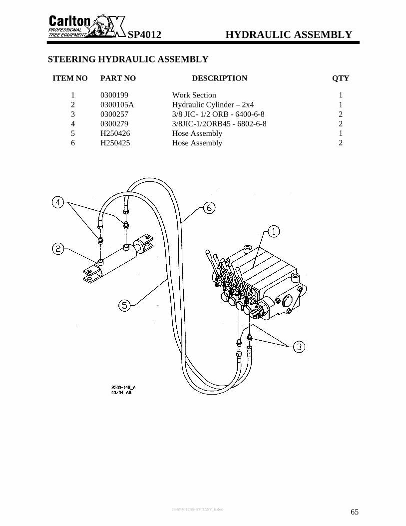
SP4012 HYDRAULIC ASSEMBLY
26-SP4012BS-HYDASY_b.doc 65
STEERING HYDRAULIC ASSEMBLY
ITEM NO PART NO DESCRIPTION QTY
1 0300199 Work Section 1 2 0300105A Hydraulic Cylinder – 2x4 1 3 0300257 3/8 JIC- 1/2 ORB - 6400-6-8 2 4 0300279 3/8JIC-1/2ORB45 - 6802-6-8 2 5 H250426 Hose Assembly 1 6 H250425 Hose Assembly 2

SP4012 HYDRAULIC ASSEMBLY
26-SP4012BS-HYDASY_b.doc 66
TRACTION HYDRAULIC ASSEMBLY
ITEM NO PART NO DESCRIPTION QTY
1 0300199 Work Section 1 2 0300138 Vickers Needle Cartridge 1 3 0300127C Deltroll Freewheel Valve Ctg 1 4 0300128 2500 Series-Parallel Module 1 5 0300120A C/B Cartridge Valve - CBCG-LKN 2 6 0300118A1 Hyd Mtr - 2500-4 Drv 2 Mtrs-RH 1 7 0300118A11 Hyd Mtr - 2500-4 Drv 2 Mtrs-LH 1 8 0300128A 2500 Flow Divider Cartridge 1 9 0300128B 2500 4W 2P Cartridge 1 10 0300128C 2500 3W 2P Cartridge 1 11 0300128D 2500 Solenoid 1 12 0300257 3/8 JIC- 1/2 ORB - 6400-6-8 2 13 0300211 3/8 JIC-5/8 ORB - 6400-6-10 4 14 0300237 3/8 JIC-3/8 ORB - 6400-6-6 6 15 H250421 Hose Assembly 1 16 H250404 Hose Assembly 1 17 H250417 Hose Assembly 2 18 H250418 Hose Assembly 2

SP4012 HYDRAULIC ASSEMBLY
26-SP4012BS-HYDASY_b.doc 67
LIFT HYDRAULIC ASSEMBLY
ITEM NO PART NO DESCRIPTION QTY
1 0300199 Work Section 1 2 0300122 Lift Valve Body - ECB 1 3 0300120 C/B Cartrdige Valve - CBCA-LHN 1 4 0300105F Hydraulic Cylinder - 3x12 1 5 0300257 3/8 JIC- 1/2 ORB - 6400-6-8 2 6 0300224 1/2FP-1/2FP-1/2MPTee5602-8 1 7 0300231 1/2MP-3/8MP Nipple - 5404-8-6 1 8 0300210 3/8 MP - 3/8 JIC - 2404-6-6 1 9 0300213 3/8 JIC - 1/4 MP 90 - 2501-6-4 1 10 H250414 Hose Assembly 1 11 H250413 Hose Assembly 1 12 H250412 Hose Assembly 1

SP4012 HYDRAULIC ASSEMBLY
26-SP4012BS-HYDASY_b.doc 68
TONGUE HYDRAULIC ASSEMBLY
ITEM NO PART NO DESCRIPTION QTY
1 0300199 Work Section 1 2 0300105B Hydraulic Cylinder - 2 1/2 x 30 1 3 0300257 3/8 JIC- 1/2 ORB - 6400-6-8 2 4 0300215 3/8JIC-1/2MP90 - 2501-6-8 2 5 H250423 Hose Assembly 1 6 H250424 Hose Assembly 1

SP4012 HYDRAULIC ASSEMBLY
26-SP4012BS-HYDASY_b.doc 69
SWING HYDRAULIC ASSEMBLY
ITEM NO PART NO DESCRIPTION QTY
1 0300199 Work Section 1 2 0300138 Vickers Needle Cartridge 1 3 0300127A 25-4 Swg Mnfld with Ndle Cvty 1 4 0300120A C/B Cartridge Valve - CBCG-LKN 2 5 0300105 Hydraulic Cylinder - 2x4 2 6 0300257 3/8 JIC- 1/2 ORB - 6400-6-8 8 7 0300219 1/2 JIC - 1/2 ORB 90 - 6801-8 4 8 H250416 Hose Assembly 1 9 H250410 Hose Assembly 1 10 H250407 Hose Assembly 1 11 H250409 Hose Assembly 1 12 H250408 Hose Assembly 1 13 H250406 Hose Assembly 1

SP4012 HYDRAULIC ASSEMBLY
26-SP4012BS-HYDASY_b.doc 70
HYDRAULIC RETURN ASSEMBLY
ITEM NO
PART NO DESCRIPTION QTY
1 0300199 Work Section 1 2 0300135E Hydraulic In Tank Filter STF 1 3 0300135F Hydraulic In Tank Filter Eleme 1 4 0300266A Hydraulic Site Gauge w/Temp 1 5 0300236 1/2 JIC-1/2 ORB- 6400-8 1 6 0300245A 1/2 JIC- 3/4 ORB - 6400-8-12 1 7 0150712H 7/16-14 x 1 1/2" SHC 2 8 0150412 7/16 Lock Washer 2 9 0150303B 7/16 Flat Washer 2 10 H250403 Hose Assembly 1

SP4012 HYDRAULIC ASSEMBLY
26-SP4012BS-HYDASY_b.doc 71
CONTROL VALVE ASSEMBLY
ITEM NO PART NO DESCRIPTION QTY
1 0300199F Work Section - SVS1GA1AA 4 2 0300199G Valve Section - SVH1BA1AA 1 3 0300199H Prince Inlet Section - SVI 1 4 0300199I Outlet Section – SVE 1 5 0300064 Relief Valve 1 6 0300261 Steel Plug, 1/2 SAE 2 7 0300072 O-Ring 1 8 0300069 Back-Up Washer 1 9 0300073 O-Ring 1 10 0300074 O-Ring 1 11 0300075 O-Ring 14 12 0300065 Relief Plug 10 13 0300199L Valve Spool End Cap 5 14 0300060 Handle Flange 5 15 0300199M Prince Handle Linkage 5 16 0300199N Prince Valve Spool Extension 5 17 0300063 Valve Handle Kit 5 18 0300076 O-Ring 4 19 0300070 Spool Back-Up Washer 10 20 0300077 O-Ring 10 21 0300078 O-Ring 16 22 0300066 Load Check Poppet 5 23 0300067 Spring 5 24 0300068 Load Check Plug 5 25 0300071 Back-Up Washer 10 26 0300079 O-Ring 10
NOTES: 1. SVS work section seal kit - P/N 0300199ZA - Includes items 11,18,20,21,25. 2. SVH work section seal kit - P/N 0300199ZB - Includes items 10,11,20,21,25. 3. SVI inlet section seal kit - P/N 0300199ZC - Includes items 10,11.

SP4012 HYDRAULIC ASSEMBLY
26-SP4012BS-HYDASY_b.doc 72
CONTROL VALVE ASSEMBLY

SP4012 HYDRAULIC ASSEMBLY
26-SP4012BS-HYDASY_b.doc 73
OPTIONAL: STEERING HYDRAULIC ASSEMBLY (ALL WHEEL DRIVE)
ITEM NO PART NO DESCRIPTION QTY
1 0300199 Work Section 1 2 0300105W Hydraulic Cylinder – 2 x 6 1 3 0300257 3/8 JIC- 1/2 ORB - 6400-6-8 2 4 1/2" O-Ring - 3/8” JIC 90° 2 5 H250426 Hose Assembly 1 6 H250425 Hose Assembly 2

SP4012 HYDRAULIC ASSEMBLY
26-SP4012BS-HYDASY_b.doc 74
OPTIONAL: TRACTION HYDRAULIC ASSEMBLY (ALL WHEEL DRIVE)
ITEM NO PART NO DESCRIPTION QTY
1 0300199 Work Section 1 2 0300138 Vickers Needle Cartridge 1 3 0300127C Deltroll Freewheel Valve Ctg 1 4 0300128 2500 Series-Parallel Module 1 5 0300120A C/B Cartridge Valve - CBCG-LKN 2 6 0300118A1 Hyd Mtr - 2500-4 Drv 2 Mtrs-RH 2 7 0300118A11 Hyd Mtr - 2500-4 Drv 2 Mtrs-LH 2 8 0300128A 2500 Flow Divider Cartridge 1 9 0300128B 2500 4W 2P Cartridge 1 10 0300128C 2500 3W 2P Cartridge 1 11 0300128D 2500 Solenoid 2 12 0300257 3/8 JIC- 1/2 ORB - 6400-6-8 2 13 0300211 3/8 JIC-5/8 ORB - 6400-6-10 8 14 0300237 3/8 JIC-3/8 ORB - 6400-6-6 6 15 0300128E SPC2 1 16 Hose Assembly 1 17 Hose Assembly 1 18 Hose Assembly 1 19 Hose Assembly 1 20 Hose Assembly 1 21 Hose Assembly 1 22 Hose Assembly 1 23 Hose Assembly 1
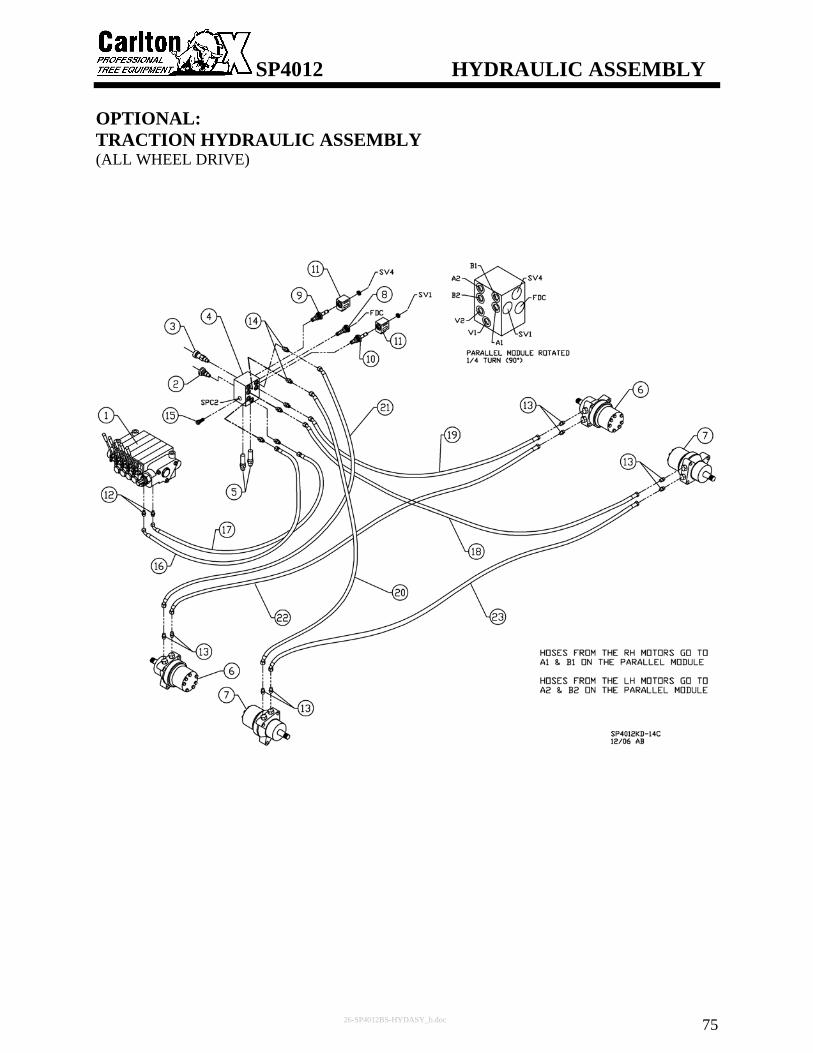
SP4012 HYDRAULIC ASSEMBLY
26-SP4012BS-HYDASY_b.doc 75
OPTIONAL: TRACTION HYDRAULIC ASSEMBLY (ALL WHEEL DRIVE)

SP4012 HYDRAULIC ASSEMBLY
26-SP4012BS-HYDASY_b.doc 76
OPTIONAL: BLADE HYDRAULIC ASSEMBLY
ITEM NO PART NO DESCRIPTION QTY
1 0300199 Work Section 1 2 0300105A Hydraulic Cylinder – 2x4 1 3 0300257 3/8 JIC- 1/2 ORB - 6400-6-8 2 4 1/2" O-Ring - 3/8” JIC 90° 2 5 Hose Assembly 1 6 Hose Assembly 1

SP4012 FRONT AXLE ASSEMBLY
27-SP4012BS-FAXLASY_c.doc 77
ITEM NO PART NO DESCRIPTION QTY
1 05500091 Tire Assembly 25-4 5 Lug 2 2 0550102 Lug Nut – 1/2-20 10 3 2300289 R/H Steering Frame 1 4 2300290 L/H Steering Frame 1 5 0550208 E/Z Lube Grease Seal 2 6 0550209 Inner Bearing – 3500# 2 7 0550210 Inner Bearing Race – 3500# 2 8 0550212 Hub w/Cups & Studs 2 9 0550213 Outer Bearing Race – 3500# 6 10 0550214 Outer Bearing – 3500# 6 11 0550215 Spindle Washer 4 12 0550216 Spindle Jam Nut - 1”-14 4 13 0550217 Tang Washer 4 14 0550218 Grease Cap - E/Z Lube – 3500# 2 15 0550219 Rubber Plug for EZ Lube Cap 2 16 3504133 Steering Linkage 1 17 2300280 Weld-on Seal Ring 2 18 12G-1010 Shoulder Bolt, 5/8” x 1 1/4" (1/2-13) 2 19 0150305 5/8 Flat Washer 2 20 0300105 Hydraulic Cylinder - 2x4 1 21 0150801 Hardened Spring Bushing - 1” 2 22 0300105N Prince Cyl. Pin – Short 2 23 1/4-28 x 2” HHCS 4 24 2300158 Ground Stake Rod - 2500 1 25 0150604 Lock Pin - 3/8 x 2 3/4 1 26 0150805 Hardened Spring Bushing - 5/8” 2 27 0150304 1/2 Flat Washer 2 28 0550104 Grease Seal – 10-9 2 29 0550109 End Cap – 3500# 2 30 0150206 1/2-13 Lock Nut 2

SP4012 FRONT AXLE ASSEMBLY
27-SP4012BS-FAXLASY_c.doc 78
Part # 8 comes complete with parts # 9, 10, 11, 12, 13, 28, & 29 as shown for front wheel. All parts can be purchased separately also.

SP4012 FRONT AXLE ASSEMBLY
27-SP4012BS-FAXLASY_c.doc 79
OPTIONAL: ALL WHEEL DRIVE
ITEM NO PART NO DESCRIPTION QTY
1 05500091 Tire Assembly 25-4 5 Lug 2 2 0550102 Lug Nut – 1/2-20 10 3 14060030 Weldment, Mount, AWD Motor, RH 1 4 14060031 Weldment, Mount, AWD Motor, LH 1 5 0550208 E/Z Lube Grease Seal 2 6 0550209 Inner Bearing – 3500# 2 7 0550210 Inner Bearing Race – 3500# 2 8 0550009H Rear Tapered Hub 25-4 2 9 0550213 Outer Bearing Race – 3500# 2 10 0550214 Outer Bearing – 3500# 2 11 0550215 Spindle Washer 2 12 0550216 Spindle Jam Nut - 1”-14 2 13 0550217 Tang Washer 2 14 0550218 Grease Cap - E/Z Lube – 3500# 2 15 0550219 Rubber Plug for EZ Lube Cap 2 16 14060033 Assy, Steering Linkage, AWD 1 17 12G-1010 Shoulder Bolt, 5/8” x 1 1/4” (1/2”-13) 2 18 0150305 5/8 Flat Washer 2 19 0150304 1/2 Flat Washer 2 20 0150206 1/2 Lock Nut 2 21 0300118A11 Hyd Mtr - 2500-4 Drv 2 Mtrs-LH 1 22 0300118A1 Hyd Mtr - 2500-4 Drv 2 Mtrs-RH 1 23 0300105W Hydraulic Cylinder 2 x 6 1 24 0300105O Prince Cyl. Pin - Long 2 25 Hitch Pin Clip (with 0300105O) 4 26 0150801 Hardened Spring Bushing - 1” 2 27 0150805 Hardened Spring Bushing - 5/8” 2 28 0150106G 1/2”-13 x 2 3/4” HHCS 8 29 Woodruff Key – 1/4” x 1” (with motor) 2 30 0150304 1/2 Flat Washer 8 31 Axle Nut – 1” Slotted Hex (with motor) 2 32 0150501 Cotter Pin – 3/16 x 2 2 33 Weld-on Seal Ring 2

SP4012 FRONT AXLE ASSEMBLY
27-SP4012BS-FAXLASY_c.doc 80
OPTIONAL: ALL WHEEL DRIVE

SP4012 REAR WHEEL ASSEMBLY
28-SP4012BS-RWHLASY.doc 81
ITEM NO PART NO DESCRIPTION QTY
1 0300118A1 Hyd Mtr - 2500-4 Drv 2 Mtrs–RH 1 2 0300118A11 Hyd Mtr - 2500-4 Drv 2 Mtrs–LH 1 3 0150304 1/2 Flat Washer 8 4 0150106G 1/2"-13 x 2 3/4" HHCS 8 5 0150206 1/2-13 Lock Nut 8 6 0550009H Rear Tapered Hub 25-4 2 7 05500091 Tire Assembly 25-4 5 Lug 2 8 0550102 Lug Nut – 1/2-20 10 9 0550009E Axle Nut - 1" Slotted Hex 2 10 0150501 Cotter Pin - 3/16” x 2” 2
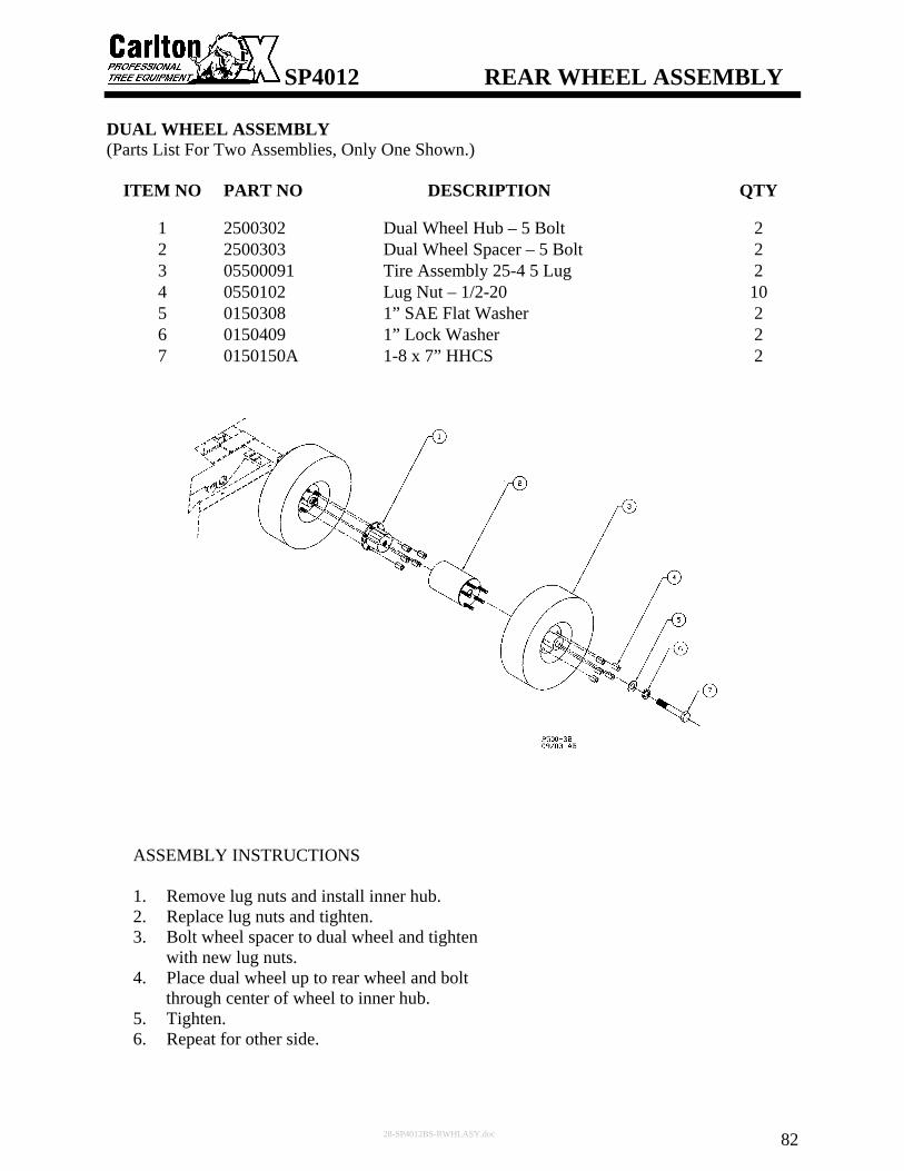
SP4012 REAR WHEEL ASSEMBLY
28-SP4012BS-RWHLASY.doc 82
DUAL WHEEL ASSEMBLY (Parts List For Two Assemblies, Only One Shown.)
ITEM NO PART NO DESCRIPTION QTY
1 2500302 Dual Wheel Hub – 5 Bolt 2 2 2500303 Dual Wheel Spacer – 5 Bolt 2 3 05500091 Tire Assembly 25-4 5 Lug 2 4 0550102 Lug Nut – 1/2-20 10 5 0150308 1” SAE Flat Washer 2 6 0150409 1” Lock Washer 2 7 0150150A 1-8 x 7” HHCS 2
ASSEMBLY INSTRUCTIONS
1. Remove lug nuts and install inner hub. 2. Replace lug nuts and tighten. 3. Bolt wheel spacer to dual wheel and tighten
with new lug nuts. 4. Place dual wheel up to rear wheel and bolt
through center of wheel to inner hub. 5. Tighten. 6. Repeat for other side.

SP4012 PIVOT ASSEMBLY
29-SP4012BS-PVTASY_B.doc 83
LOWER PIVOT ASSEMBLY TWO WHEEL DRIVE WITH TONGUE EXTENSION
ITEM NO PART NO DESCRIPTION QTY
1 2300189 Lift Pivot Shaft - 2500 1 2 0150801 Hardened Spring Bushing - 1" 8 3 0150308 1" SAE Flat Washer 2 4 0150209 1-14 Hex Castle Nut 2 5 0150501 Cotter Pin - 3/16" x 2" 2 6 0300105F Hydraulic Cylinder - 3x12 1 7 0300105O Prince Cyl. Pin - Long 2 8 Hitch Pin Clip (with 0300105O) 2 9 2500162 Side Pivot Tube 2500 2
10 2500280 Side Pivot Gusset 2500 2 11 2300125 Pivot Shaft Tube 2500 1 12 0150600 Grease Fitting –1/4 NPT 3 13 H250429 Grease Hose Assembly – 42” 1 14 H250428 Grease Hose Assembly – 41” 1 15 H250427 Grease Hose Assembly – 40” 1 16 0300346 1/4 MJIC - 1/8 NPT- 2405-4-2 3
PARTS # 9 & 10 ARE WELDED TO THE PIVOT ASSEMBLY AFTER THE BOOM IS LEVEL #11 IS WELDED IN THE FRAME ASSEMBLY
♦
♦♦♦

SP4012 PIVOT ASSEMBLY
29-SP4012BS-PVTASY_B.doc 84
UPPER PIVOT ASSEMBLY
ITEM NO PART NO DESCRIPTION QTY
1 2300159 Swing Pivot Shaft - 1" - 23/25 1 2 0150801 Hardened Spring Bushing - 1" 4 3 0500201 Race - 23/25 # 15250 2 4 0500121 Bearing - 1" - 23/25 # 15100 2 5 0500407 Seal - 23/25 2 6 2300255 Top Pivot Inner Bushing – 2500 1 7 2300256 Bottom Pivot Bushing - 2500 1 8 0150208 1-14 Hex Jam Nut 2 9 0150209 1-14 Hex Castle Nut 1
10 0150501 Cotter Pin - 3/16" x 2" 1 11 0150123 5/16-18 x 3/4 SHCP 6 12 0150124 5/16-18 x 3/4 FHSCP 6 13 2300257 Top Pivot Bushing - 2500 1 14 0300105N Prince Cyl. Pin – Short 4 15 1/4"-28 x 2" HHCS 8 16 0500500 Snap Ring for 2500 Pivot 2.5” 2 17 0150308 1" SAE Flat Washer 1 18 0150600 Grease Fitting – 1/4 NPT 1 19 Pop-Out Valve 1 20 2300107 Boom Pivot Tube 1
♦ PART #20 IS WELDED IN THE PIVOT ASSEMBLY
♦
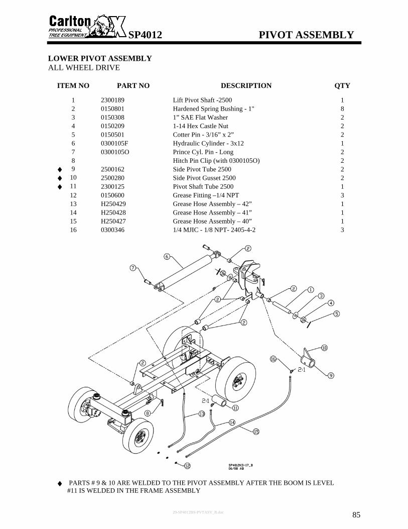
SP4012 PIVOT ASSEMBLY
29-SP4012BS-PVTASY_B.doc 85
LOWER PIVOT ASSEMBLY ALL WHEEL DRIVE
ITEM NO PART NO DESCRIPTION QTY
1 2300189 Lift Pivot Shaft -2500 1 2 0150801 Hardened Spring Bushing - 1" 8 3 0150308 1” SAE Flat Washer 2 4 0150209 1-14 Hex Castle Nut 2 5 0150501 Cotter Pin - 3/16” x 2” 2 6 0300105F Hydraulic Cylinder - 3x12 1 7 0300105O Prince Cyl. Pin - Long 2 8 Hitch Pin Clip (with 0300105O) 2 9 2500162 Side Pivot Tube 2500 2
10 2500280 Side Pivot Gusset 2500 2 11 2300125 Pivot Shaft Tube 2500 1 12 0150600 Grease Fitting –1/4 NPT 3 13 H250429 Grease Hose Assembly – 42” 1 14 H250428 Grease Hose Assembly – 41” 1 15 H250427 Grease Hose Assembly – 40” 1 16 0300346 1/4 MJIC - 1/8 NPT- 2405-4-2 3
PARTS # 9 & 10 ARE WELDED TO THE PIVOT ASSEMBLY AFTER THE BOOM IS LEVEL #11 IS WELDED IN THE FRAME ASSEMBLY
♦♦♦
♦

SP4012 BOOM ASSEMBLY
30-SP4012BS-BOOMASY_e.doc 86
ENGINE SLIDE ASSEMBLY
ITEM NO PART NO DESCRIPTION QTY
1 0200140A 35HP Briggs Vanguard Engine 1 2 14040074 Mount, Engine, Briggs 1 3 0150104 3/8”-16 x 2 1/2” Hex Cap Screw 4 4 0150303 3/8” Flat Washer 8 5 0150207 3/8”-16 Lock Nut 8 6 14040079 Weldment, Engine Slide, Briggs 1 7 0150125A 5/8”-11 x 2” HHCS 4 8 0150408 5/8” Lock Washer 4 9 0150305 5/8” Flat Washer 4 10 14040045 Rod, Engine Slide 2 11 0150104A 3/8”-16 x 2 1/4” Hex Cap Screw 4 12 14040083 Weldment, Engagement Handle 1 13 0250216 Bushing JA x 7/8 2 14 0150401 #10 Lock Washer 6 15 0150101 #10-24 x 3/4" SHCS 6 16 14040049 Weldment, Engine Rod Adjust, Mount 1 17 0150703A Split Lock Collar- 7/8 2 18 14040090 Rod, Engagement 1 19 14040091 Assy, Engagement Linkage, Adjust 1 20 14040092 Assy, Slide Lock Adjust 1 21 0150801 Hardened Spring Bushing – 1” 4 22 HOI-125 Snap Ring 4 23 14040051 Plate, Latch, Engine Slide 1 24 0150102 1/4”-20 x 1” Hex Cap Screw 1 25 0150218 1/4”-20 Lock Nut 1 26 A106T018 Key - 3/16 Sq. x 1 1/16 2 27 0150601 Grease Fitting – 1/4”-28 Str. 8

SP4012 BOOM ASSEMBLY
30-SP4012BS-BOOMASY_e.doc 87
ENGINE SLIDE ASSEMBLY

SP4012 BOOM ASSEMBLY
30-SP4012BS-BOOMASY_e.doc 88
ENGINE BELT ASSEMBLY
ITEM NO PART NO DESCRIPTION QTY
1 05506101 Bee Hive- Briggs/Kawaski 1 2 0150712A 7/16”-14 x 1 3/4” Hex Bolt 2 3 0150412 7/16” Lock Washer 4 4 14040109 Bee Hive Belt Keeper - Top 1 5 0150712B 7/16”-14 x 2” Hex Bolt 2 6 14040110 Bee Hive Belt Keeper - Bottom 1 7 14040111 Belt Keeper,Guard,Briggs 1 8 0150404 3/8” Lock Washer 9 9 0250120 Bushing - 25 JS,CW - SK 1 7/16 1 10 0250322 Sheave 6-3V5.3 SP4012 Vangrd 1 11 0150102C 1/4”-20 x 2” Hex Bolt 3 12 A160T015 Key – 3/8 Sq x 2 3/4 1 13 0250133 Coupling - 23/25 Engine 1 14 0150120 5/16”-18 x 1” HSHCS 2 15 0250134 Spider Insert - 23/25 1 16 0250132 Coupling - 23/25 Pump 1 17 2300199 Pump Mounting Plate-2500 1 18 0300142G Hyd Pump 4012- Bucher 1 19 20 0150118A 3/8”-16 x 1 1/4” Hex Bolt 2 21 0150207 3/8”-16 Lock Nut 6 22 0150118B 3/8”-16 x 1 1/2” Hex Bolt 2 23 14040081 Weldment, Engine Belt Guard Base, Briggs 1 24 0150117 3/8”-16 x 1” Carriage Bolt 1 25 0150303 3/8” Flat Washer 13 26 0400142A Belt 4012 Briggs 6/3V710 1 27 14040067 Weldment, Engine Belt Guard Cover, Briggs 1 28 0150117A 3/8”-16 x 1 1/4" Carriage Bolt 1 29 14040112 Tubing – Belt Keeper – Jackshaft Sheave 2 30 0150115A 1/2-13 x 5 Square Head Bolt 2 31 0150304 1/2" Flat Washer – Hardened 2 32 0150206 1/2"-13 Lock Nut 2

SP4012 BOOM ASSEMBLY
30-SP4012BS-BOOMASY_e.doc 89
ENGINE BELT ASSEMBLY

SP4012 BOOM ASSEMBLY
30-SP4012BS-BOOMASY_e.doc 90
JACK SHAFT ASSEMBLY
ITEM NO PART NO DESCRIPTION QTY
1 2700D185 Jackshaft – 1 11/16” 1 2 A160T011 Key - 3/8” x 1 3/4” 1 3 A160T012 Key – 3/8” x 2 1/4” 1 4 0500113 Bearing – 1 11/16” – Link Belt 2 5 0150125 5/8”-11 x 2 1/2” HHCS 4 6 0150305 5/8” Flat Washer 8 7 0150216 5/8”-11 Lock Nut 4 8 0250321 Sheave 6-3V14.0 SP4012 Vangrd 1 9 0250212 Bushing SF 1 11/16” 1 10 0250115F1 2012 1 11/16" Taper Lock Bshn 1 11 0250115A PC Sprkt 8M-40S-62 Taper Lock 1 12 0150712H 7/16”-14 x 1 1/2” SHC 2 13 0150114A 1/2”-13 x 3 1/2” Square Hd Scrw 2 14 0150205 1/2”-13 Hex Nut 6 15 0150407 1/2” Lock Washer 3 16 0150115 1/2”-13 x 4” Square Head Screw 1
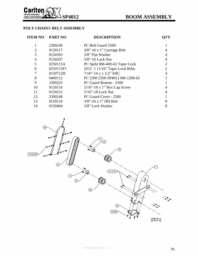
SP4012 BOOM ASSEMBLY
30-SP4012BS-BOOMASY_e.doc 91
POLY CHAIN® BELT ASSEMBLY
ITEM NO PART NO DESCRIPTION QTY
1 2300249 PC Belt Guard 2500 1 2 0150117 3/8”-16 x 1” Carriage Bolt 4 3 0150303 3/8” Flat Washer 4 4 0150207 3/8”-16 Lock Nut 4 5 0250115A PC Sprkt 8M-40S-62 Taper Lock 2 6 0250115F1 2012 1 11/16" Taper Lock Bshn 2 7 0150712H 7/16”-14 x 1 1/2” SHC 4 8 0400112 PC 2300 2500 SP4012 8M-1200-62 1 9 2300225 PC Guard Bottom - 2500 1 10 0150116 5/16”-18 x 1” Hex Cap Screw 4 11 0150212 5/16”-18 Lock Nut 4 12 2300248 PC Guard Cover - 2500 1 13 0150118 3/8”-16 x 1” HH Bolt 8 14 0150404 3/8” Lock Washer 8

SP4012 BOOM ASSEMBLY
30-SP4012BS-BOOMASY_e.doc 92
CUTTER WHEEL ASSEMBLY
ITEM NO PART NO DESCRIPTION QTY
1 2700D184 Cutter Wheel Shaft 1 11/16” 1 2 0500113 Bearing – 1 11/16” – Link Belt 2 3 0150125B 5/8”-11 x 2 3/4” HHCS 4 4 0150305 5/8” Flat Washer 8 5 0150216 5/8”-11 Lock Nut 4 6 A160T013 Key - 3/8 x 1 7/8 1 7 A160T014 Key - 3/8 x 3 1 8 0250122 Bushing - 35/44 JS -SK 1 11/16 1 9 2300186 Cutter Wheel – 23/25 1 10 2300188 Cutter Wheel Hub – SK600A 1 11 2700D194 2 1/2 CW Shaft Washer- 1 11/16 1 12 2700D195 3 1/2 CW Shaft Washer- 1 11/16 1 13 0250115A PC Sprkt 8M-40S-62 Taper Lock 1 14 0250115F1 2012 1 11/16" Taper Lock Bshn 1 15 0150712H 7/16”-14 x 1 1/2” SHC 2 16 2300197 Shaft Washer 1 7/16” 1 17 0150106B 1/2”-13 x 1 1/4” Hex Cap Screw 1 18 0450106 Round Pocket - C/S 10 19 0450107 Round Pocket - Thd. 10 20 0450101 Tooth - Straight 2 21 0450102 Tooth - Right 45 Degree 9 22 0450103 Tooth - Left 45 Degree 9 23 0450109 Tooth Bolt - 5/8-18 x 2 1/8” 20

SP4012 BOOM ASSEMBLY
30-SP4012BS-BOOMASY_e.doc 93
CUTTER WHEEL ASSEMBLY

SP4012 BOOM ASSEMBLY
30-SP4012BS-BOOMASY_e.doc 94
CUTTER WHEEL ASSEMBLY (SANDVIK WHEEL OPTION)
ITEM NO PART NO DESCRIPTION QTY
1 2700D184 Cutter Wheel Shaft 1 11/16” 1 2 0500113 Bearing – 1 11/16” – Link Belt 2 3 0150125B 5/8”-11 x 2 3/4" HHCS 4 4 0150305 5/8” Flat Washer 8 5 0150216 5/8”-11 Lock Nut 4 6 A160T013 Key - 3/8 x 1 7/8 1 7 A160T014 Key - 3/8 x 3 1 8 0250122 Bushing - 35/44 JS -SK 1 11/16 1 9 14030053 Sandvik Cutter Wheel Weldment 1 10 2300188 Cutter Wheel Hub - SK600A 1 11 2700D194 2 1/2 CW Shaft Washer- 1 11/16 1 12 2700D195 3 1/2 CW Shaft Washer- 1 11/16 1 13 0250115A PC Sprkt 8M-40S-62 Taper Lock 1 14 0250115F1 2012 1 11/16" Taper Lock Bshn 1 15 0150712H 7/16”-14 x 1 1/2” SHC 2 16 2300197 Shaft Washer 1 7/16” 1 17 0150106B 1/2”-13 x 1 1/4” Hex Cap Screw 1 18 0450130 JP Sandvik Plow Bolt Tooth 24 19 0450131 JP Sandvik Short P/B Tooth 8 20 0450132 JP Sandvik Plow Bolt Holder 24 21 0450125 Sandvik Stover Jam Nut 32

SP4012 BOOM ASSEMBLY
30-SP4012BS-BOOMASY_e.doc 95
CUTTER WHEEL ASSEMBLY (SANDVIK WHEEL OPTION)

SP4012 CHIP GUARD ASSEMBLY
31-SP4012BS-CGASY_a.doc 96
ITEM NO PART NO DESCRIPTION QTY
1 2300134 2500 Deck Plate - R/H 1 2 2300135 2500 Deck Plate - L/H 1 3 0150119 3/8-16 x 3/4 Carriage Bolt 30 4 0150303 3/8 Flat Washer 34 5 0150207 3/8-16 Lock Nut 34 6 2300310 Front Rubber Chip Guard 1 7 2300311 Side Rubber Chip Guard 2 8 0150133H 3/4-10 x 6” Hex Head Bolt 1 9 2300218 Chip Guard Front Bracket 2
10 2300217 Chip Guard Side Bracket 2 11 2300193 Pan Guard - 2500 1 12 0150106B 1/2-13 x 1 1/4" Hex Cap Screw 2 13 0150206 1/2-13 Lock Nut 2 14 2300221 Boom Chip Guard Deck 1 15 0150117 3/8-16 x 1” Carriage Bolt 4 16 2300313 Front Boom Rubber Chip Guard 1 17 2300312 Side Boom Rubber Chip Guard 2 18 2300234 Chip Guard Bracket 4 19 2300261 Cutter Wheel Flap - 2500 1 20 0150211 3/4-10 Lock Nut 1 21 0150116 5/16-18 x 1” Hex Cap Screw 1 22 0150212 5/16-18 Lock Nut 1

STUMP CUTTERS
32-SP4012BS-Back.doc
MODEL TYPE ENGINE HP FUEL CUTTING
DEPTH CUTTINGHEIGHT
CUT SWING
NO. TEETH
WHEELDIA.
WHEEL THICKNESS
TONGUE EXTENSION
WEIGHT(lbs.)
900H Walk- Behind Honda 13 Gas 9" 21" N/A 12 12.25" .5" N/A 220
SP2000 Walk- Behind Kohler 27 Gas 24" 27" N/A 16 19" .5" N/A 695
Self- Propelled Kohler 27 Gas 13" 34" 40" arc 20 21" 1" 30" 1,550
Self- Propelled
Briggs- Vanguard 35 Gas 13" 34" 40" arc 20 21" 1" 30" 1,650 SP4012
Self- Propelled Lombardini 28.7 Diesel 13" 34" 40" arc 20 21" 1" 30" 1,650
SP7015 Self- Propelled Deutz Turbo 60 Diesel 15" 43" 70" arc 32 26.5" 1" N/A 3,500
SP7015TRX Track- Mounted Deutz Turbo 60 Diesel 15" 43" 70" arc 32 26.5" 1" N/A 4,300
SP8018 TRX Track- Mounted Deutz Turbo 78 Diesel 18" 43" 80" arc 32 26.5" 1" N/A 5,420
HURRICANE RS
Track- Mounted
John Deere Turbo 140 Diesel 25" 53" 360° 48 31" 1.5" N/A 8,500
Track- Mounted
John Deere Turbo 140 Diesel 25" 72" 360° 64 36" 1.5" N/A 12,000
Track- Mounted
John Deere Turbo 175 Diesel 25" 72" 360° 64 36" 1.5" N/A 12,000
HURRICANE TRX
Track- Mounted
John Deere Turbo 250 Diesel 25" 72" 360° 64 36" 1.5" N/A 12,000
3500D Tow- Behind Deutz Turbo 60 Diesel 15" 40" 80" arc 32 26.5" 1" 48" 2,900
7500 Tow- Behind Deutz Turbo 78 Diesel 24" 46" 92" arc 48 31" 1.5" 60" 4,400
Call and ask about Carlton’s line of Chippers or visit our website: www.stumpcutters.com CARLTON—QUALITY PRODUCTS AND EXCEPTIONAL SERVICE
Carlton Owner’s Manual SP4012 Revised: 10/2008