assembly instructions safety rules parts list loaders/truck_loader_archive... · assembly...
TRANSCRIPT
ASSEMBLY INSTRUCTIONS SAFETY RULES PARTS LIST
35hp series Truck Loader
Actual product differs from product pictured above
Model No. Description 3800023 TLB35252BVG
Manual No. 3100011Revision: - 01/01/09
1 preliminaries Congratulations! You have just purchased one of the finest pieces of outdoor power equipment on the market today. If properly cared for, your new truck loader will provide years of dependable service. Please read and follow this instruction manual carefully in order to get the most out of your new equipment. As you carefully uncrate your unit, you will find the following items: 1 Power Unit
1 Discharge Stack &Elbow Assembly 1 12” x 6’ Metal Discharge Hose (standard units) 1 16” x 7’ Intake Hose (standard units) 1 Horizontal Hose Support Boom Member 1 Parts Accessory Kit including:
1 – 16” Intake Nozzle 4 – 16” Hose Clamps 1 – Hose Support Boom Horizontal Member 1 – 12” Squeeze Ring 1 – Package of assembly hardware 1 – Package containing operating manuals and warranty registration
Each product leaves our factory in excellent condition; occasionally, however, some damage may occur during shipment. If any such damage is found upon initial inspection, immediately notify the transport carrier who delivered your machine, as they are solely responsible for such damage, as well as any subsequent adjustments necessary. Before assembly, please take a moment and record your model number and serial number below for future reference (both numbers are located on the silver tag adhered to the engine side of the impeller housing assembly): Model number_______________________________ Serial number________________________________ Also be sure to promptly fill out and return the warranty registration enclosed in your manual packet. Your new loader requires very little assembly. Simply follow the instructions contained within this manual to begin enjoying the benefits of your new unit.
CALIFORNIA PROPOSITION 65 WARNING
Gasoline and Diesel engine exhaust and some of its constituents are known to the State of California to cause cancer, birth defects and other reproductive harm. As an owner of off-road gasoline or diesel engine equipment and/or as an employer, you also may have an obligation under the California Occupational Safety and Health Act or under Proposition 65 to warn persons exposed to gas and diesel engine exhaust and/or other Proposition 65 chemicals in and around your workplace. See California Health and Safety Code section 25249.5, Title 22 of the California Code of Regulations at Section 1200 er seq., and Title 8 of the California Code of Regulations Section 5194.
R0603.1
2 safety rules regarding outdoor power equipment
PLEASE READ THE FOLLOWING BEFORE ASSEMBLING OR OPERATING UNIT TRAINING • Read, understand, and follow all instructions in the manual and on the unit before starting. If the operator(s) or mechanic(s) can not read English it is the owner’s responsibility to explain this material to them. • Become familiar with the safe operation of the equipment, operator controls, and safety signs. • All operators and mechanics should be trained. The owner is responsible for training the users. • Only allow responsible adults, who are familiar with the instructions, to operate the unit. • Never let children or untrained people operate or service the equipment. Local regulations may restrict the age of the operator. • The owner/user can prevent and is responsible for accidents or injuries occurring to themselves, other people or property. PREPARATION • Evaluate the terrain to determine what accessories and attachments are needed to properly and safely perform the job. Use only accessories and attachments approved by the manufacturer. • Wear appropriate clothing including safety shoes, safety glasses and ear protection. Long hair, loose clothing or jewelry may get tangled in moving parts. • Inspect the area where the equipment is to be used and remove rocks or any other such objects which can damage the machine or the receiver box. • Use extra care when handling gasoline and other fuels. They are flammable and vapors are explosive. a) Use only an approved container. b) Never remove fuel cap or add fuel with the engine running. Allow engine to cool before refueling. Do not smoke. c) Never refuel or drain the machine indoors. • Check that operator’s presence controls, safety switches and shields are attached and functioning properly. Do not operate unless they are functioning properly.
OPERATION • Never run an engine in an enclosed area. • Operate only in the daylight or with good artificial light, keeping away from holes and hidden hazards. • Be sure all components are securely in place and in good operating order before starting engine. • Be sure of your footing while using equipment, especially when backing up. Walk, don’t run. • Do not operate the unit without discharge connected to a debris receiver box. • Slow down and use caution when making turns and when changing directions on slopes. • Never leave a running unit unattended. Always stop engine, and remove keys before leaving unit. • Never operate without guards securely in place. Be sure all safety features are attached, adjusted properly and functioning properly. • Never operate with intake or discharge components loose, removed or altered. • Do not change the engine governor setting or over speed the engine. • Stop on level ground, shut off engine before leaving the operator’s position for any reason including emptying the receiver box or unclogging the intake or discharge. • Stop equipment and inspect impeller blades after picking up unusually large or hard objects or abnormal vibration occurs. Make necessary repairs before resuming operations. • Keep hands and feet away from the intake and discharge. • Never carry passengers and keep pets and bystanders away. • Do not operate the unit while under the influence of alcohol or drugs. • Slow down and use caution when making turns and crossing roads and sidewalks. • Use care when hooking or unhooking the machine to a towing vehicle. • Use care when approaching blind corners, shrubs, trees or other objects that may obscure vision.
2 safety rules regarding outdoor power equipment (cont.) SLOPE OPERATION Slopes are a major factor related to loss-of-control and tip-over accidents, which can result in severe injury or death. All slopes require extra caution. If you cannot back up the slope, or if you feel uneasy on it, do not operate on it. Do • Remove obstacles such as rocks, tree limbs, etc. • Watch for holes, ruts, or bumps. Uneven terrain could overturn the unit. Tall grass can hide obstacles. • Use slow speed. • Keep all movement on the slopes slow and gradual. Do not make sudden changes in speed or direction. Do Not • Do not start or stop on a slope. If tires lose traction, stop the unit and proceed slowly straight down the slope. • Do not turn on slopes unless necessary, and then, turn slowly and gradually downhill, if possible. • Do not operate near drop-offs, ditches, or embankments. The operator could lose footing or balance or unit could suddenly turn over if a wheel is over the edge of a cliff or ditch, or if an edge caves in. CHILDREN Tragic accidents can occur if the operator is not alert to the presence of children. Children are often attracted to the unit and its activity. Never assume that children will remain where you last saw them. • Keep children out of the operating area and under the watchful care of another responsible adult. • Be alert and turn unit off if children enter the area. • Before and during reverse operation, look behind and down for small children. • Never carry children. They may fall off and be seriously injured or interfere with safe unit operation. • Never allow children to operate the unit. • Use extra care when approaching blind corners, shrubs, trees, or other objects that may obscure vision.
EMISSIONS • Engine exhaust from this product contains chemicals known, in certain quantities, to cause cancer, birth defects, or other reproductive harm. • Look for the relevant Emissions Durability Period and Air Index information on the engine emissions label. MAINTENANCE AND STORAGE • Always observe safe refueling and fuel handling practices when refueling the unit after transportation or storage. • Always follow the engine manual instructions for storage preparations before storing the unit for both short and long term periods. • Always follow the engine manual instructions for proper start-up procedures when returning the unit to service. • Never store the machine or fuel container inside where there is an open flame, such as in a water heater. Allow unit to cool before storing. • Shut off fuel while storing or transporting. Do not store fuel near flames or drain indoors. • Keep all hardware, especially impeller bolt, tight and keep all parts in good working condition. Replace all worn or damaged decals. • Never tamper with safety devices. Check their proper operation regularly. • Clean debris from units, drives, mufflers, and engine to prevent fires. Clean up oil or fuel spillage. • Stop and inspect the equipment if you strike an object. Repair, if necessary, before restarting. • Never make adjustments or repairs with the engine running unless specified otherwise. • Park machine on level ground. Never allow untrained personnel to service machine. • Use jack stands to support components when required. • Carefully release pressure from components with stored energy. (e.g. springs) • Check impeller on a regular basis for bent, worn or cracked blades. Only replace impellers; never straighten or weld them. • Keep hands and feet away from moving parts.
2 safety rules regarding outdoor power equipment (cont.) • Belts and belt guard components are subject to wear, damage, and deterioration, which could expose moving parts or allow objects to be thrown. Frequently check components and replace with manufacturer’s recommended parts, when necessary. • Check operation of brake, tail and license lights frequently. replace as required. • Use only factory authorized replacement parts when making repairs.
• Always comply with factory specifications on all settings and adjustments. • Only authorized service locations should be utilized for major service and repair requirements. • Never attempt to make major repairs on this unit unless you have been properly trained. Improper service procedures can result in hazardous operation, equipment damage and voiding of manufacturer’s warranty.
3 unit assembly & set-up Note: Please refer to Parts List for correct part identification and placement. Parts list reference numbers are called out by sheet number followed by reference number(s) on that sheet: (1:1) indicates Sheet 1, reference number 1; (2:32,34-38) indicates Sheet 2, reference numbers 32 through 38 excluding 33; etc.
Important Safety Note: To prevent unit rollover during assembly and set up, lock rear support leg in lowermost position possible. Failure to do this may result in injury or death and/or damage to unit or property.
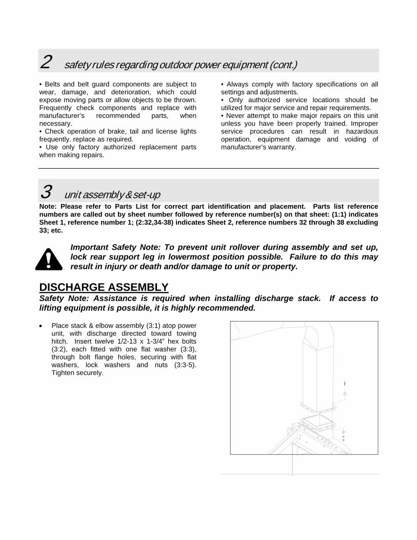
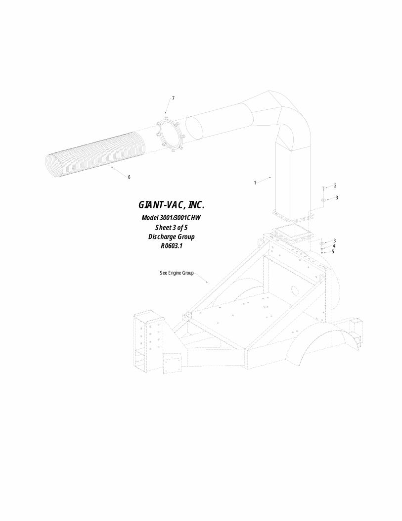
DISCHARGE ASSEMBLY Safety Note: Assistance is required when installing discharge stack. If access to lifting equipment is possible, it is highly recommended. • Place stack & elbow assembly (3:1) atop power
unit, with discharge directed toward towing hitch. Insert twelve 1/2-13 x 1-3/4” hex bolts (3:2), each fitted with one flat washer (3:3), through bolt flange holes, securing with flat washers, lock washers and nuts (3:3-5). Tighten securely.
3 unit assembly & set-up (cont.)
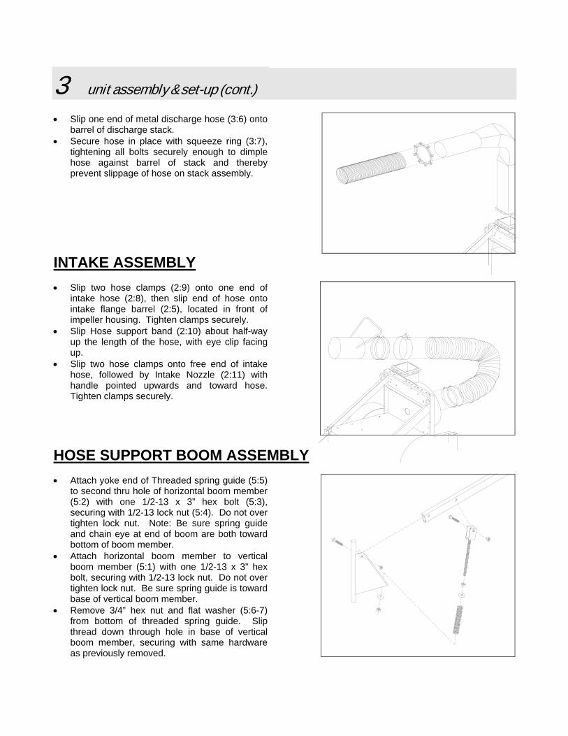
• Slip one end of metal discharge hose (3:6) onto
barrel of discharge stack. • Secure hose in place with squeeze ring (3:7),
tightening all bolts securely enough to dimple hose against barrel of stack and thereby prevent slippage of hose on stack assembly.
INTAKE ASSEMBLY • Slip two hose clamps (2:9) onto one end of
intake hose (2:8), then slip end of hose onto intake flange barrel (2:5), located in front of impeller housing. Tighten clamps securely.
• Slip Hose support band (2:10) about half-way up the length of the hose, with eye clip facing up.
• Slip two hose clamps onto free end of intake hose, followed by Intake Nozzle (2:11) with handle pointed upwards and toward hose. Tighten clamps securely.
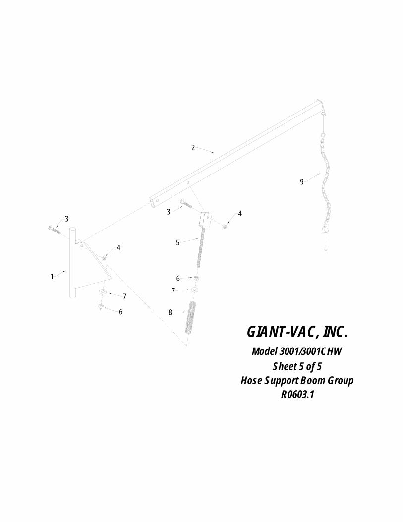
HOSE SUPPORT BOOM ASSEMBLY • Attach yoke end of Threaded spring guide (5:5)
to second thru hole of horizontal boom member (5:2) with one 1/2-13 x 3” hex bolt (5:3), securing with 1/2-13 lock nut (5:4). Do not over tighten lock nut. Note: Be sure spring guide and chain eye at end of boom are both toward bottom of boom member.
• Attach horizontal boom member to vertical boom member (5:1) with one 1/2-13 x 3” hex bolt, securing with 1/2-13 lock nut. Do not over tighten lock nut. Be sure spring guide is toward base of vertical boom member.
• Remove 3/4” hex nut and flat washer (5:6-7) from bottom of threaded spring guide. Slip thread down through hole in base of vertical boom member, securing with same hardware as previously removed.
3 unit assembly & set-up (cont.)
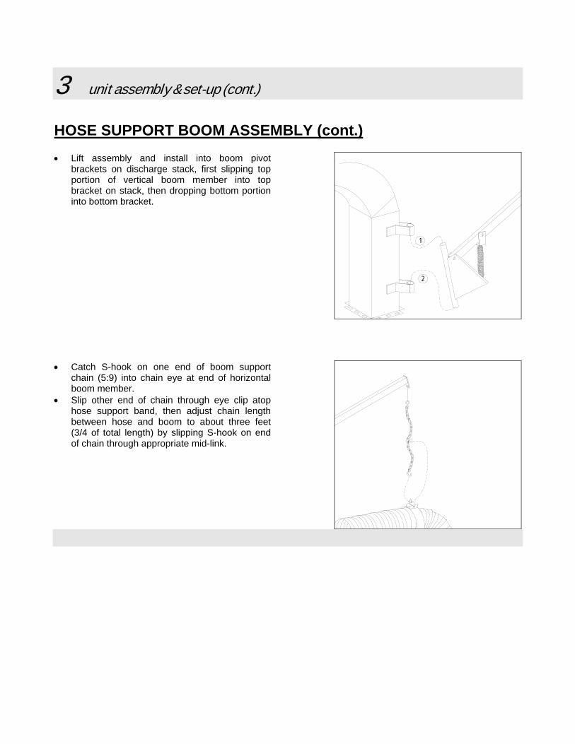
HOSE SUPPORT BOOM ASSEMBLY (cont.)• Lift assembly and install into boom pivot
brackets on discharge stack, first slipping top portion of vertical boom member into top bracket on stack, then dropping bottom portion into bottom bracket.
1
2
• Catch S-hook on one end of boom support
chain (5:9) into chain eye at end of horizontal boom member.
• Slip other end of chain through eye clip atop hose support band, then adjust chain length between hose and boom to about three feet (3/4 of total length) by slipping S-hook on end of chain through appropriate mid-link.

3 unit assembly & set-up (cont.)
DEBRIS BOX CONSTRUCTION
WARNING: This unit is designed to be used in conjunction with a debris collection box. NEVER run or operate your Truck Loader without a debris box.
Below are directions for constructing a simple, sturdy debris box for use in a standard pickup bed: • Cut four pieces of 3” angle iron to the inside length of the truck bed, four pieces to the inside width, then four
pieces that measure from the truck bed floor to approximately 8” higher than the top of the unit discharge when the unit is connected to the truck. Either weld or securely bolt the box frame together.
• Line the inside front and sides with 3/4” exterior grade plywood. • Cover the top of the frame with a heavy duty mesh screening to allow for adequate ventilation. • Cut a plywood door the width and height of the box frame. Install a heavy duty hinge at the top of the door
and fasten it to the rear of the box frame. Install latches or other locking mechanisms between the lower sides of the door and the box sides to keep the door from opening inadvertently.
• Mark the location on the door where the unit discharge meets the box, then cut a 16” diameter hole in the door at that location. Install a rubber gasket around the hole to prevent debris blow-by – an old 13” or 14” inner tube works fine.
CONNECTING UNIT TO TOWING VEHICLE • Install appropriate trailer plug onto end of unit wiring harness to match socket on towing vehicle. Wiring
scheme is as follows: Red – Right signal Yellow – Left signal Brown – Taillights Green – Ground
• Raise or lower support jack until unit sits level with ground. Back towing vehicle up to draw bar, then visually check draw bar for proper height alignment with hitch receiver on vehicle. Raise or lower draw bar if needed by relocating in any of the remaining sets of height adjustment holes.
• With assistance behind, back up slowly, aligning both draw bar with hitch receiver and discharge hose with receiver box opening.
• Lock pintle ring in hitch receiver, connect safety chains to vehicle in a criss-cross fashion to cradle draw bar in case of accidental disconnect, then connect wiring harness plug into trailer socket of vehicle.
• Lift rear support leg and pin in uppermost position. Note: To prevent possible rollover, lock rear support leg in lowermost position possible when unit is parked or disconnected from towing vehicle.
Your unit is now ready to be started and checked for proper operation. See your engine manual for proper engine prep and operation.

4 unit operation GENERAL GUIDELINES TO OBSERVE DURING OPERATION
• Never allow a person to ride, sit or stand on the unit. Never allow a person to ride, sit or stand on the towing vehicle other than in the driver’s cab of the towing vehicle.
• Make sure that the driver of the towing vehicle has the operator of the unit in full view at all
times. Also, when operating the unit, instruct the operator to stay to the side of the machine, never in front or behind.
• Collecting debris into piles for the machine to intercept prior to startup will save time and fuel
as well as wear and tear on the unit.
• We recommend the following for the most efficient performance: if debris is very dry, run the machine at approximately half throttle; this will help reduce the amount of small particles of debris escaping through the ventilation screen. If debris is wet or partially frozen, run the machine at full throttle.
• Lower intake hose boom assembly until nozzle floats 2-3 inches from the ground, then adjust
engine throttle so that when nozzle is pushed to the ground, suction can be broken with moderate effort using three fingers of one hand. This will make operation relatively easy and comfortable.
• Time and experience will be your best guide in finding the most efficient performance from
your unit.
UNCOUPLING UNIT FROM TOWING VEHICLE
• Disconnect taillight/brakelight plug from towing vehicle receiver.
• Unhook safety chains from rear of towing vehicle.
• Crank down wheel jack until unit weight is lifted from towing vehicle.
• Drop rear support leg to lowermost position and secure with clevis and bridge pin. Note: Failure to follow this step can result in unit rollover and serious personal injury and unit damage.
• Open pintle receiver latch on towing vehicle, determine if pintle ring on unit will clear pintle
receiver on vehicle (crank down wheel jack an additional turn or two if not), and pull vehicle away.

5 unit maintenance
GENERAL MAINTENANCE NOTE: Some maintenance services, such as engine repairs, electrical repairs, etc., should be performed only by a qualified technician.
• Check overall condition of unit prior to each use, repairing or replacing worn, damaged or missing components promptly. Check all fasteners regularly and tighten if necessary.
• Follow engine manufacturer’s recommendations for maintenance schedules. Use only
recommended parts, fluids and lubricants. Failure to follow manufacturer’s recommendations may void manufacturer’s warranties.
• Lubricate impeller shaft bearings every 50 hours of operation. Use a high quality bearing
grease, available from your local dealer (or auto parts store).
• Maintain tire pressure as indicated on tire sidewall. Replace worn or damaged tires promptly.
• Keep engine free from a buildup of grass, leaves or excessive grease. An accumulation of these combustible materials may result in a fire, or simply impede performance.
• Never change attachments or make any adjustments, repairs or replacements until the unit is
completely shut down and the battery is disconnected.
5 unit maintenance (cont.) STORAGE
• Keep the unit in locked storage to prevent unauthorized individuals, especially chidren, from playing and/or tampering with the unit.
• When storing the unit for prolonged periods, it is recommended to disconnect the battery.
• Store fuel in an approved, clearly marked container.
• NO NOT store gasoline powered equipment or fuel containers in any closed area where heat-
radiating appliances or open pilot lights are present, unless the fuel has been completely drained from the power equipment and the fuel containers.
REPLACEMENT PARTS Replacement parts are available from your local Giant-Vac dealer.
warranty
GIANT-VAC, INC., here-in-after called Giant-Vac, warrants each new Giant-Vac to the original retail purchaser of the new Giant-Vac equipment to be free from manufacturing defects in normal service for a period of 1 year, unless it is used for rental purposes, which limits the warranty to 30 days. This warranty does not apply to engines, tires or other parts that are purchased and warranted by their manufacturer. Items such as bags, grass catchers, hoses and blades are not warranted, as these are considered expendable items. This warranty does not include equipment failures due to normal wear. Any obligation under this warranty is expressly limited to the replacement or repair, at an authorized servicing Giant-Vac dealer, or at a point designated by us, of such parts as appear to us to have been defective. All defective parts have to be returned freight prepaid before credit will be issued. We shall not be liable for transportation charges in connection with the replacement or repair of defective parts. This warranty does not apply to a Giant-Vac upon which repairs or alterations have been made by others except with our prior written approval. We shall not be liable for consequential damages or contingent liabilities for the fitness of any Giant-Vac for any particular purpose. We make no other express, implied or statutory warranty, nor is anyone authorized to make any in our behalf.
535 Macon Street
McDonough, GA 30253 PHONE: 866-792-8223
8
10
9
11
121314
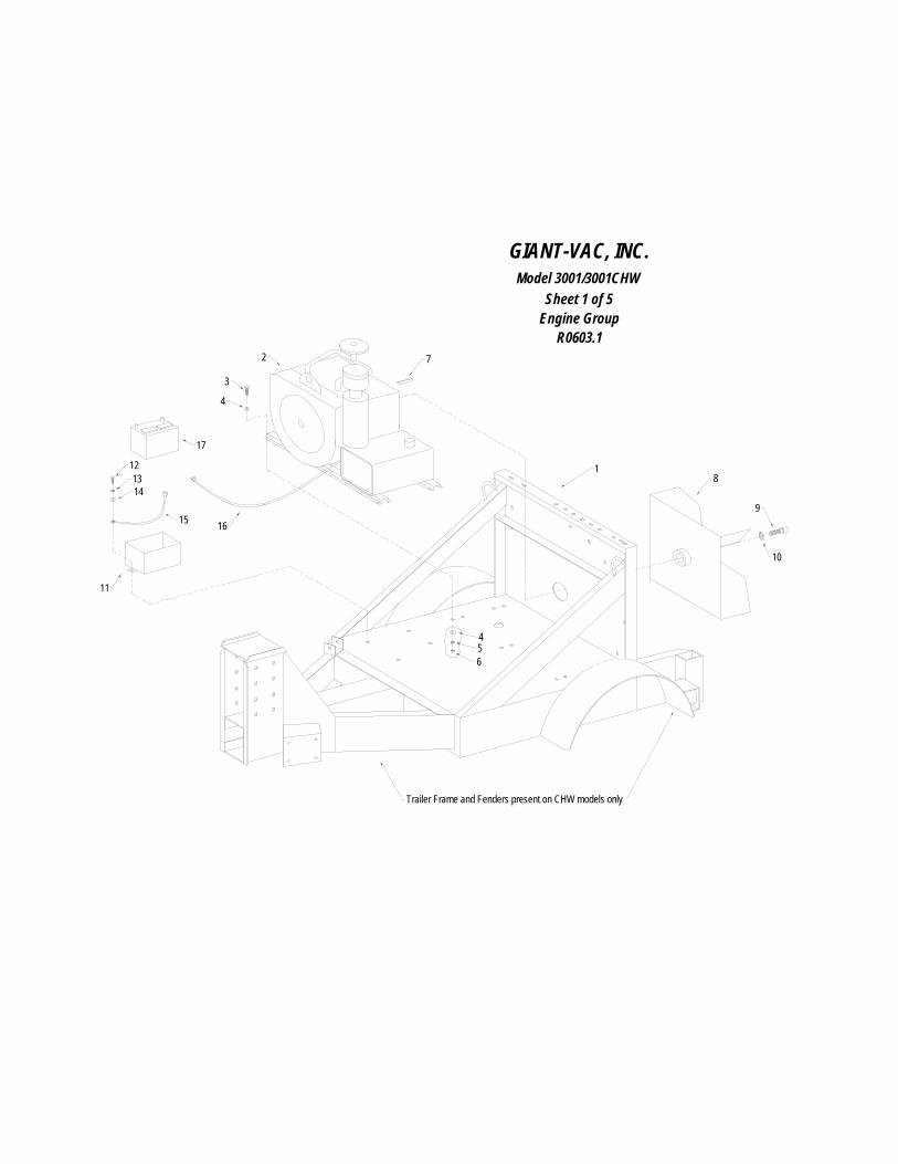
GIANT-VAC, INC.Model 3001/3001CHW
Sheet 1 of 5Engine Group
R0603.1
456
4
3
15 16
17
1
Trailer Frame and Fenders present on CHW models only
72

Giant-Vac Model TLB35252BVG Truck LoaderSheet 1 - Engine Group
REF. PARTNO. NO. DESCRIPTION QTY
1 10201 Loader Base - SKID 11 10250 Loader Base and Trailer Frame - TM Model 12 39043 35 HP Briggs & Stratton Engine 13 31097 3/8-16 x 1-1/4 Hex Bolt (Engine Mounting Bolt) 44 31034 3/8 Flat Washer 85 31008 3/8 Lock Washer 46 31009 3/8-16 Hex Nut 47 31127 Impeller Key 18 21518 Impeller 1
9&10 31327 Kit 5-8-11 x 1-3/4 Impeller Bolt and Lock Washer 111 39101 Battery Box (Plastic) 115 31642 Battery Cable, Ground 32S 116 31826 Battery Cable, Positive - 48S 117 39018 Battery 1
Items Not Shown
31453 Pusher Bolts 340185 Fuel Tank (2009 EPA) 131828 Compression Fitting 1/4 x 1/4 131753 Copper Tubing 1/4 140173 Fuel Tank Cap (2009 EPA) 131755 Fuel Line Rubber 1/4 139190 Valve, Oil Drain 161215 Lock-on Hose 1/2 161233 Hydraulic Adapter 14MM 161234 Seal 14MM 134041 Clamp 1/2 237172 Guard, Belt Bearing Pulley 137173 Guard, Belt Engine Pulley 137174 Guard, Belt Bearing Box Right Side 137175 Guard, Belt Bearing Box Left Side 136344 Belt, 450-5 136347 Sheave, Pulley 6.90 136340 Bushing 1.438 136346 Sheave, Pulley 4.75 136233 Bushing 1.438 136163 Bearing 1.438 236345 Shaft, Impeller 131458 Collar, Single Split 1.438 2
1
2
3 4
5
6 7
8
9
9 1011
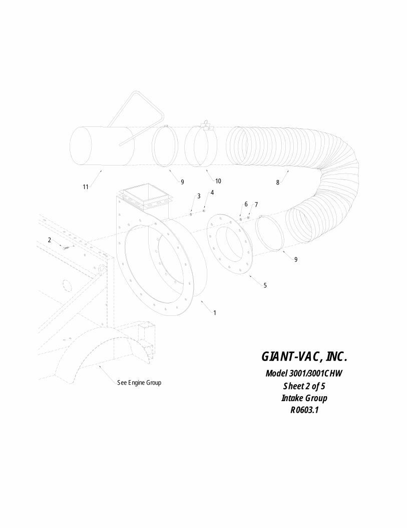
GIANT-VAC, INC.Model 3001/3001CHW
Sheet 2 of 5Intake Group
R0603.1
See Engine Group
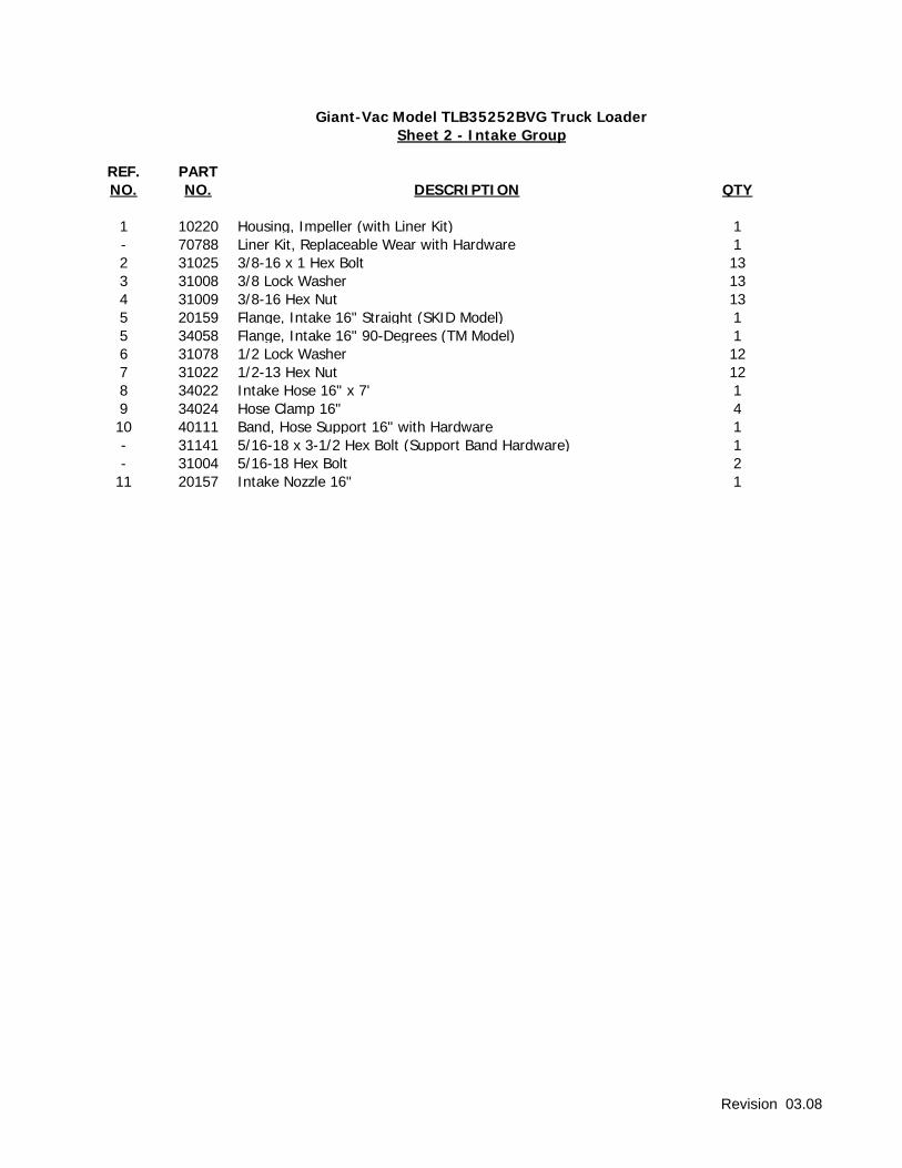
Giant-Vac Model TLB35252BVG Truck LoaderSheet 2 - Intake Group
REF. PARTNO. NO. DESCRIPTION QTY
1 10220 Housing, Impeller (with Liner Kit) 1- 70788 Liner Kit, Replaceable Wear with Hardware 12 31025 3/8-16 x 1 Hex Bolt 133 31008 3/8 Lock Washer 134 31009 3/8-16 Hex Nut 135 20159 Flange, Intake 16" Straight (SKID Model) 15 34058 Flange, Intake 16" 90-Degrees (TM Model) 16 31078 1/2 Lock Washer 127 31022 1/2-13 Hex Nut 128 34022 Intake Hose 16" x 7' 19 34024 Hose Clamp 16" 410 40111 Band, Hose Support 16" with Hardware 1- 31141 5/16-18 x 3-1/2 Hex Bolt (Support Band Hardware) 1- 31004 5/16-18 Hex Bolt 2
11 20157 Intake Nozzle 16" 1
Revision 03.08
1 2
3
345
7
6
GIANT-VAC, INC.Model 3001/3001CHW
Sheet 3 of 5Discharge Group
R0603.1
See Engine Group
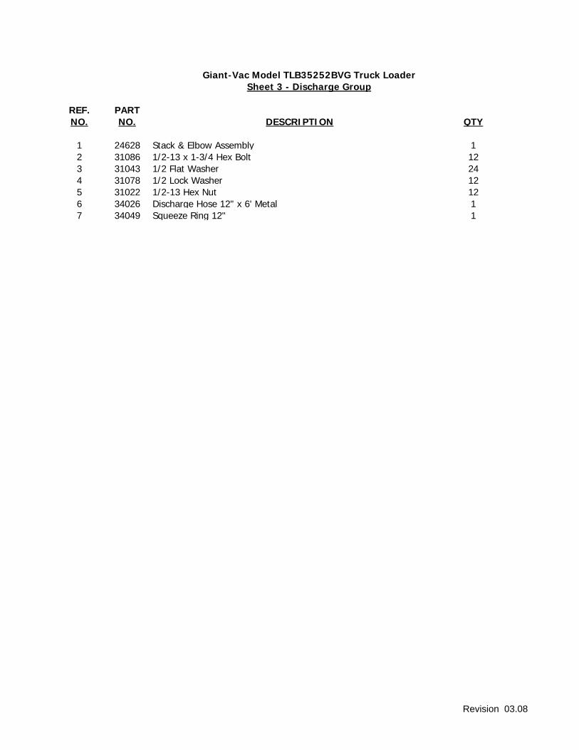
Giant-Vac Model TLB35252BVG Truck LoaderSheet 3 - Discharge Group
REF. PARTNO. NO. DESCRIPTION QTY
1 24628 Stack & Elbow Assembly 12 31086 1/2-13 x 1-3/4 Hex Bolt 123 31043 1/2 Flat Washer 244 31078 1/2 Lock Washer 125 31022 1/2-13 Hex Nut 126 34026 Discharge Hose 12" x 6' Metal 17 34049 Squeeze Ring 12" 1
Revision 03.08
thru
See Engine Group2
3
4
5
67
8
9
7
10
11
1213
14
15
1617
1819
20
21
22
23
25
24
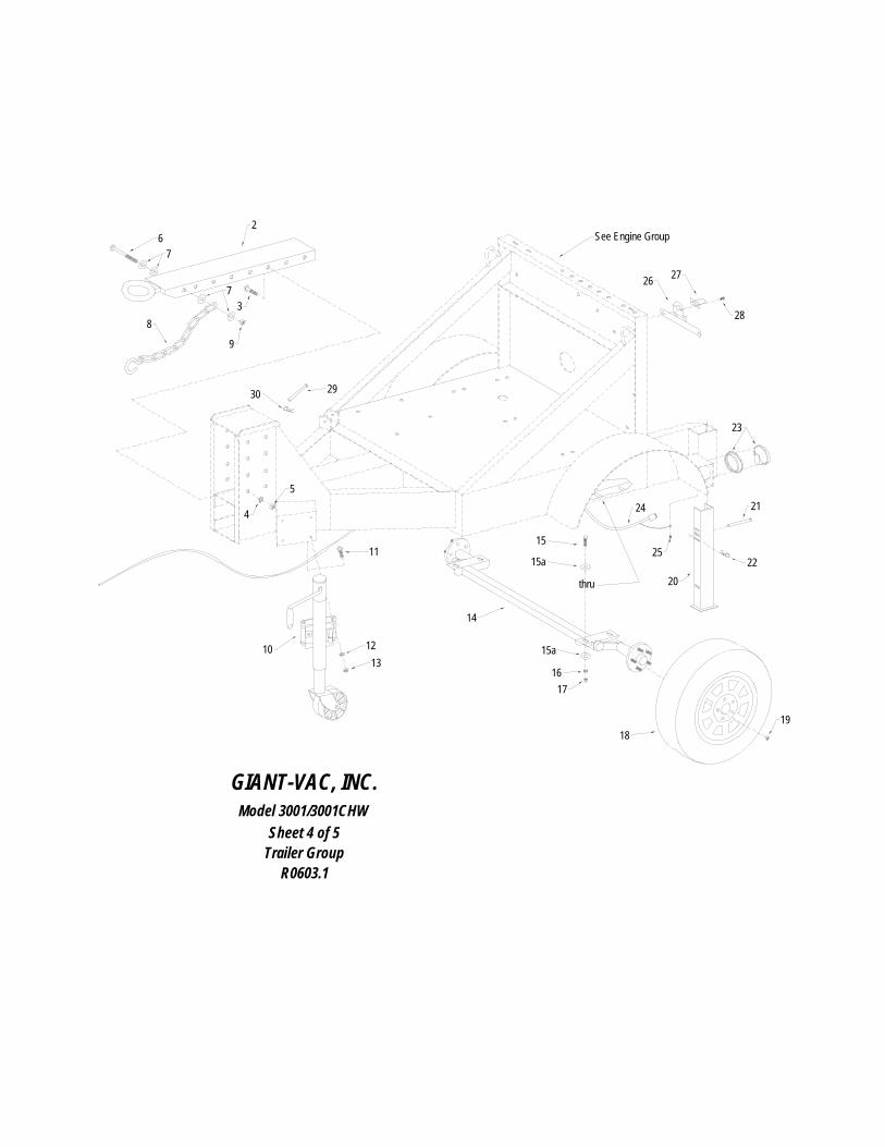
GIANT-VAC, INC.Model 3001/3001CHW
Sheet 4 of 5Trailer Group
R0603.1
29
15a
15a
26 27
28
30
NO. NO. DESCRIPTION QTY
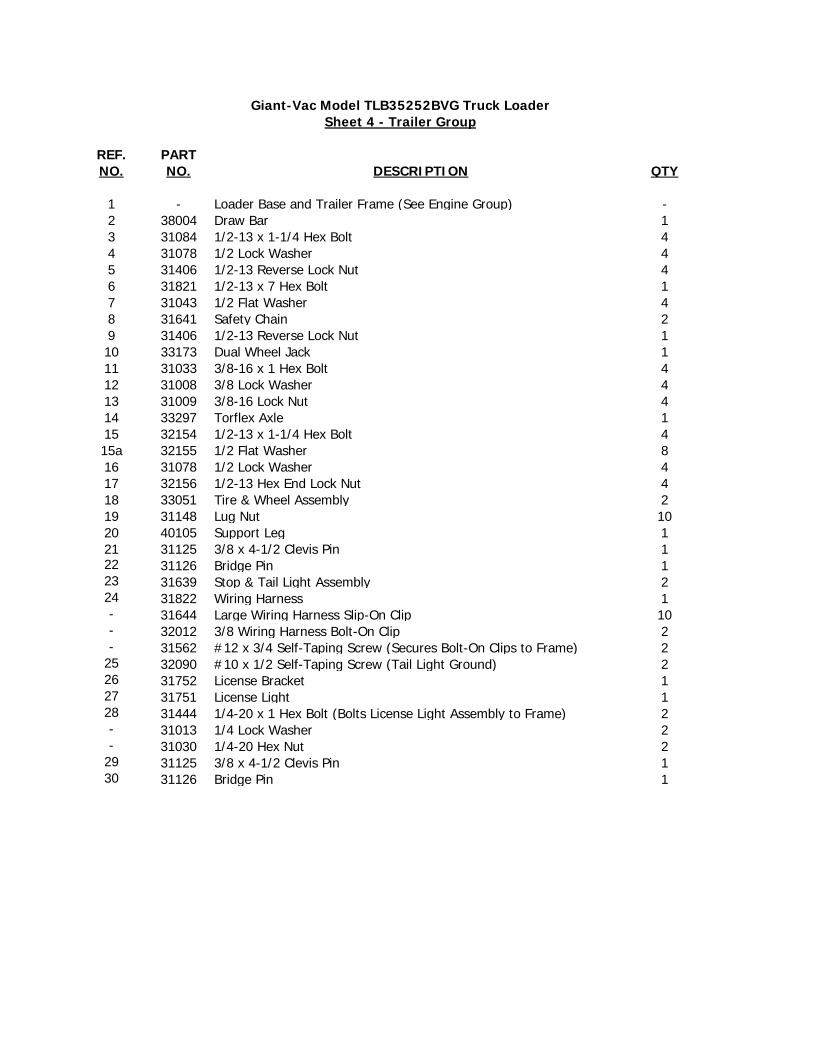
30 31126 Bridge Pin 1
Sheet 4 - Trailer GroupGiant-Vac Model TLB35252BVG Truck Loader
REF. PART
1 - Loader Base and Trailer Frame (See Engine Group) -2 38004 Draw Bar 13 31084 1/2-13 x 1-1/4 Hex Bolt 44 31078 1/2 Lock Washer 45 31406 1/2-13 Reverse Lock Nut 46 31821 1/2-13 x 7 Hex Bolt 17 31043 1/2 Flat Washer 48 31641 Safety Chain 29 31406 1/2-13 Reverse Lock Nut 110 33173 Dual Wheel Jack 111 31033 3/8-16 x 1 Hex Bolt 412 31008 3/8 Lock Washer 413 31009 3/8-16 Lock Nut 414 33297 Torflex Axle 115 32154 1/2-13 x 1-1/4 Hex Bolt 415a 32155 1/2 Flat Washer 816 31078 1/2 Lock Washer 417 32156 1/2-13 Hex End Lock Nut 418 33051 Tire & Wheel Assembly 219 31148 Lug Nut 1020 40105 Support Leg 121 31125 3/8 x 4-1/2 Clevis Pin 122 31126 Bridge Pin 123 31639 Stop & Tail Light Assembly 224 31822 Wiring Harness 1- 31644 Large Wiring Harness Slip-On Clip 10- 32012 3/8 Wiring Harness Bolt-On Clip 2- 31562 #12 x 3/4 Self-Taping Screw (Secures Bolt-On Clips to Frame) 2
25 32090 #10 x 1/2 Self-Taping Screw (Tail Light Ground) 226 31752 License Bracket 127 31751 License Light 128 31444 1/4-20 x 1 Hex Bolt (Bolts License Light Assembly to Frame) 2- 31013 1/4 Lock Washer 2- 31030 1/4-20 Hex Nut 2
29 31125 3/8 x 4-1/2 Clevis Pin 1
1
2
3
4
3 4
5
67
8
7
6
9
GIANT-VAC, INC.Model 3001/3001CHW
Sheet 5 of 5Hose Support Boom Group
R0603.1

Giant-Vac Model TLB35252BVG Truck LoaderSheet 5 - Hose Support Boom Group
REF. PARTNO. NO. DESCRIPTION QTY
1 40107 Boom Vertical Member 12 40106 Boom Horizontal Member 13 31025 1/2-13 x 3 Hex Bolt 24 31406 1/2-13 Reverse Lock Nut 25 40108 Threaded Spring Guide 16 31110 3/4-10 Hex Nut 37 31023 3/4 Flat Washer 28 31332 Boom Spring 19 31140 Boom Chain 1
Revision 03.08