model l77 -17 serial # 2004-8899999 - orionsupport.orionpackaging.com/pdf_manuals/l77-17-en.pdfsteel...
TRANSCRIPT
MODEL L77-17 SERIAL # 2004-8899999
2270 Industrial boul. , Montreal (Laval), Canada, H7S 1P9 Tel.: (450) 667-9769, Fax: (450) 667-6320
INSTRUCTION MANUAL
FOR ALL INQUIRIES PLEASE CONTACT
OUR LOCAL DISTRIBUTOR
FOR NORTH AMERICA ONLY 1-800-333-6556

Thank you for choosing ORION stretch-wrapping equipment. It is a wise choice, which will benefit your company now and in the future. ORION uses a unique combination of functional, rugged steel structure and sophisticated control systems to offer equipment high in durability and low in maintenance requirements. Our advance control systems mean that Orion equipment can be operated safely and efficiently without the need for special operator expertise. Please read this manual carefully and keep it handy. Following these simple operating instructions will insure the safe and efficient performance of this machine while simple maintenance procedures will guarantee a long and productive life of the equipment.
Notice: Our manual covers standard features of the machine. Certain options may not be fully covered due to their unique application. In order to acquire more information about custom made features of your machine and to provide quicker service, the following information is required when making an inquiry: 1)Model 2)Serial Number 3)Subassembly ( see PART LIST ) SAFETY: ORION'S stretch wrappers should be operated with caution and common sense as any other industrial equipment. To prevent injury and/or electrical shocks, careful operation of the machine and awareness of its many automatic functions is required. NOTE: All electrical power and compressed air must to be disconnected prior to all inspection, maintenance or repair work.
ORION PACKAGING INC.

ORION PACKAGING SYSTEMS INC. SEMI-AUTOMATIC SPECIFICATIONS - EFFECTIVE SEPTEMBER 1st, 2000
REVISED APRIL 2001
ORION EPIC SERIES MODEL L-77
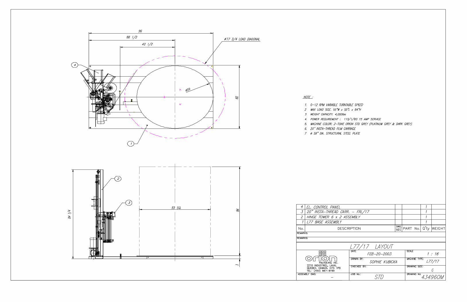
Spiral Semi-Automatic Medium Duty Low Profile Maximum Load Size 55”W x 55”L x 84”H Weight Capacity 4,000 Ibs. Dynamic, 20,000 Ibs. Static Utilities 115/1/60 15 Amp Service Turntable 59” Diameter Structural Steel Plate
Dura-Glide Turntable Support System Quiet in Operation, Maintenance Free 3” Height Floor to Top of Turntable
Turntable Drive 0-12 RPM Variable Turntable Speed Variable Speed Drive Motor Heavy Duty Chain Drive with Tensioner Electronically Adjustable Acceleration/Deceleration (Soft Start) Positive Alignment Feature
Control Features CSA Approved, NEMA 12 Control Panel State-of-the-Art Logic Control User Friendly Microprocessor with Micro-Switch Keypad Revo-Logic Exact Wrap Counting Technology Electronic Film Tension Control Adjustment on the Panel Separate Top I Bottom Wrap Count Selectors with LED Count Display Variable Speed Film Carriage Up/Down Control Film Carriage Raise/Lower Switch (Manual) Photocell for Automatic Load Height Detection Turntable Jog Pushbutton
Film Delivery 20” Insta-Thread LT Powered Pre-Stretch Film Delivery System 200% Pre-Stretch Ratio Easy & Safe to Operate Self-Threading Carriage Design Electronic Film Tension Control Adjustment on the Panel Variable Speed Film Output (Non-Wearing Sensor) Heavy Duty Chain & Sprocket Ratio Control Adjustable Film Roping Bar on Chassis for Stronger Interlocking of Load and Pallet
Film Carriage Elevator Drive Heavy Duty ANSI Chain Carriage Lift
Variable Speed Drive Motor Multi-Point UHMW Precision Carriage Guidance System
Structural Features 100% Structural Steel Construction Throughout Easy Access to All Components Open Mechanical Design for Ease of Maintenance Forklift Portable Base Design Structural Steel Tube Mast Design Hinged Mast for Ease of Shipping, Portability
Estimated Shipping Weight 1,500 Ibs.
Visit our Distributor Support Website at www.support.orionpackaging.com
MACHINE UNLOADING INSPECTION & INSTALLATION
UNLOADING Machine can be easily unloaded and transported by a forklift with a minimum capacity of 2500 lbs. 1. Carefully insert the forks into the lifting tubes to the maximum possible depth. Depending on the model, a forklift access may be either at the turntable end of the machine frame, the tower end or both. In case of the mongoose machine enter the forks under the frame or insert the forks in the tube brackets welded to the top of the machine. 2. Lift the machine (or other part of system) only to the necessary height to move it wi th no bouncing or friction on the floor. 3. Sit the machine down assuring uniform contact with the floor, which is necessary to ensure correct and smooth operation. INSPECTION 1. Remove all packing and supporting additions - these may include the blocks under the carriage and the restraining bar over the table. NOTE: when removing the stretchwrap film covering the machine, care must be taken not to cut any of the electrical wires and/ or polyurethane covering on the film carriage rollers. 2. Perform a visual inspection of the electrical and mechanical parts for loosened joints and / or broken connections. Any suspected shipping damage must be reported immediately to the freight carrier. Any transport damage cannot be claimed to Orion Packaging Inc. Items that are vulnerable to damage and must be inspected are as follows:
- Motors and transmissions - Junction boxes - Electrical conduits - Proximity and limit switches - Photocells
3. Check under the turntable to ensure that there is no crippling of the movable parts i.e. casters, center axle or drive assembly. 4.Verify the following: - Turntable or rotary arm drive system to confirm that the reducer to drive the chain is snug and properly aligned. - Verify the wires tight conduits for crushed sections or loose fittings. - Verify the film carriage to be sure that it is correctly aligned with the tower - Verify the tension on the lift chain. - Verify all the dials and knobs on the control panel for smooth action.
MACHINE INSTALLATION After the visual inspection has been completed, the electrical power and the compressed air shall be connected as specified on the diagrams supplied with the machine. An electrical diagram is provided with each machine in the envelope attached to the panel box. ASSEMBLY PROCEDURE The structural frames of the machine have to be installed on a leveled floor. Locate the main wrapper section into its final position, keeping the tower assembly* away from any traffic. The wrapper mainframe section must be bolted to the floor by the 1/2” concrete floor anchors (leg & shield or expandable type). Any wiring that has been disconnected to facilitate transport is marked with a number located on the junction box to which the wiring must be reconnected. Any wire run that appears too short or long may indicate that the position of the mechanical components is incorrect. Verify the status of all assemblies before proceeding. * The tower deviation from vertical must not exceed 1/4” on the distance of 10 feet (angle: 0 degrees 6’). CONTROL PANEL In the case of the free standing panel (console) place it adjacent to the system and anchor firmly to the floor. Connect the liquid tight (rigid conduit) to the main junction box located on the wrapper main frame next to the tower.
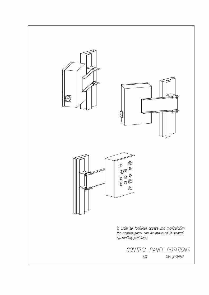


Fig. 1 Keyboard/Display

Fig. 2 755.2 Microprocessor Board & 755.1 Keyboard
Turntable Momentary Position Sensor
Carriage Run
Carriage Down
Carriage Up
TT Start Stop Photocell
Ribbon Cable
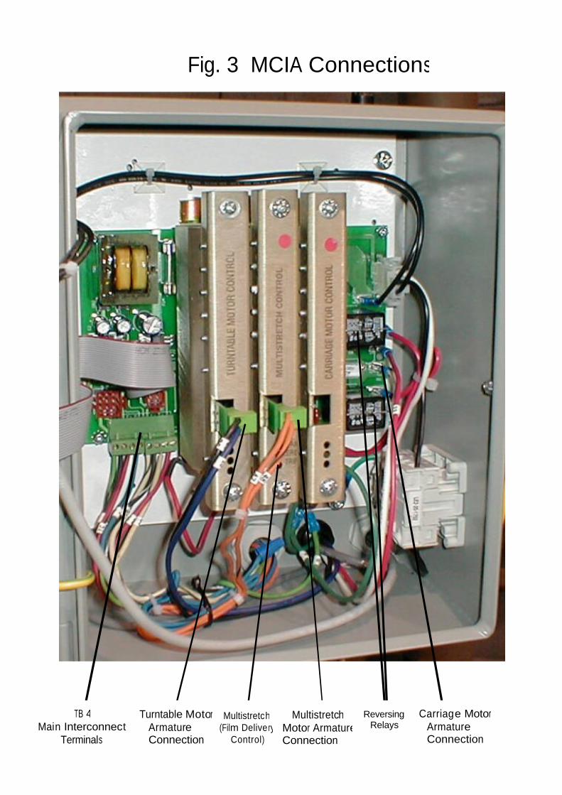
Fig. 3 MCIA Connections
TB 4 Main Interconnect
Terminals
Turntable Motor Armature Connection
Multistretch (Film Delivery
Control)
Multistretch Motor Armature Connection
Reversing Relays
Carriage Motor Armature Connection
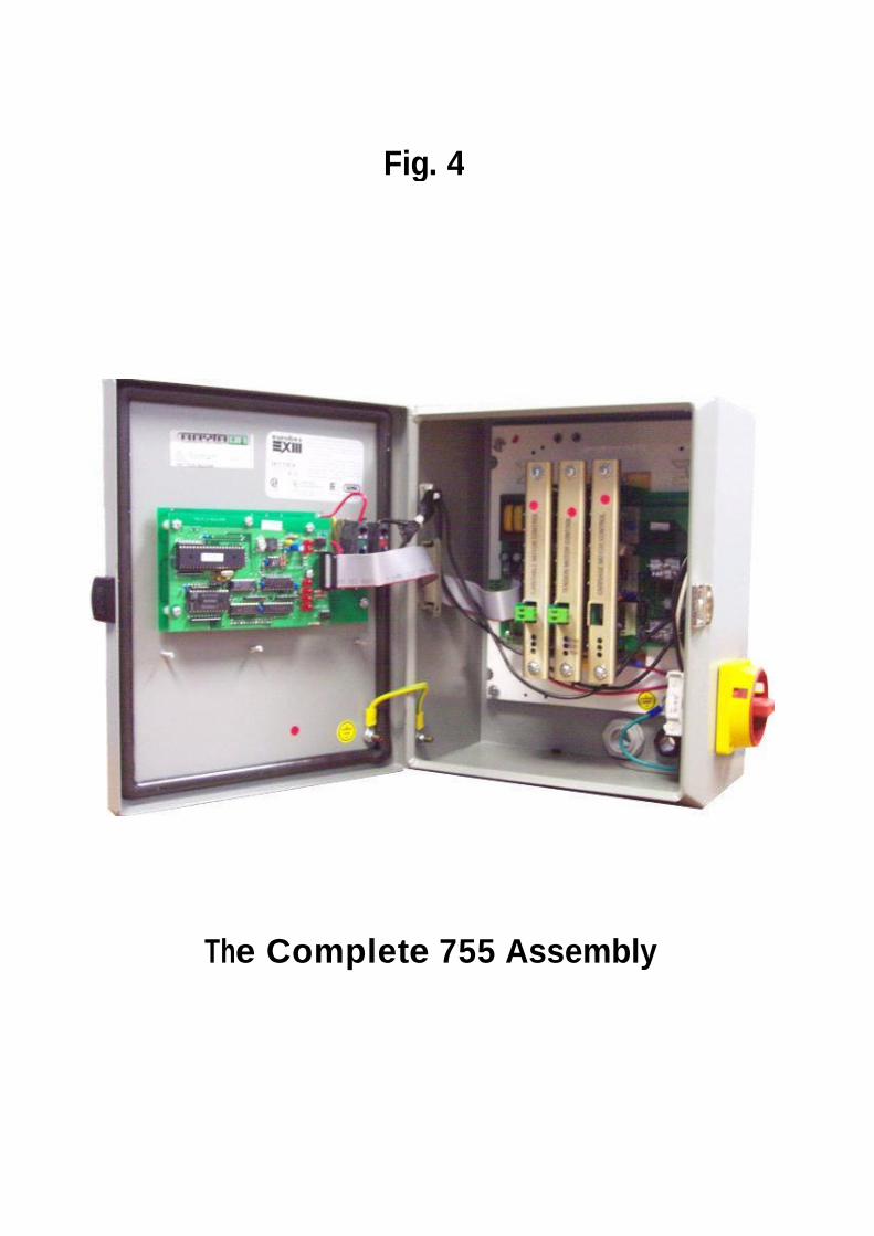
Fig. 4
The Complete 755 Assembly

Fig 5
Carriage Control
Multistretch Control
Turntable Control

755 Orion Integrated Digital Control Center
OPERATING INSTRUCTIONS
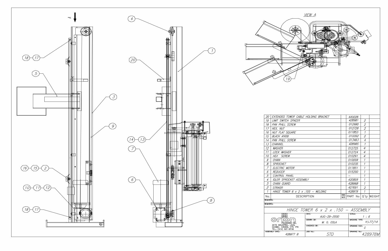
HL77-17

TABLE OF CONTENTS SECTION 1 GENERAL DESCRIPTION ....................................................................................2 1.1 Reference drawing ............................................................................................2 1.2 Description of sub -assemblies ........................................................................2 1.3 Multistretch control description........................................................................3 1.4 Turntable control description...........................................................................4 1.5 Carriage control description.............................................................................4 SECTION 2 KEYBOARD DESCRIPTION.................................................................................5 SECTION 3 MANUAL OPERATION ..........................................................................................6 3.1 Turntable jog ......................................................................................................6 3.2 Carriage jog up & down....................................................................................6 SECTION 4 PROGRAMMING OF WRAPPING PATTERNS.................................................6 4.1 Top & bottom wrap ............................................................................................6 4.2 Film tension........................................................................................................7 4.3 Carriage up & down speed ..............................................................................7 4.4 Spiral up / up & down........................................................................................7 4.5 Photo eye............................................................................................................8 4.6 Default setting ....................................................................................................8 SECTION 5 MODE OF OPERATION........................................................................................8 5.1 Cycle start ...........................................................................................................8 5.2 Pause / stop .......................................................................................................8 SECTION 6 ADVANCED PARAMETERS SETTING ..............................................................9 6.1 Parameter description ......................................................................................9 6.2 Accessing parameters ......................................................................................9 6.3 Parameter saving ..............................................................................................9 6.4 Get default settings ...........................................................................................10 6.5 Exit function........................................................................................................10 SECTION 7 DISPLAY SCREEN.................................................................................................10 7.1 Display contents ................................................................................................10 7.2 Display refresh...................................................................................................10 SECTION 8 MAINTENANCE ......................................................................................................11 8.1 Replacing sub assemblies ...............................................................................11 8.2 Board-level maintenance .................................................................................11 SECTION 9 TROUBLE-SHOOTING ..........................................................................................11 SECTION 10 SPARES PARTS .....................................................................................................12
Page 1

SECTION 1 General Description
The system is an integrated control for a stretchwrapping machine. It includes three DC motor controls:
• Carriage control, reversing. • Turntable control, fully programmable via keyboard interface. • Multistretch control, fully programmable via keyboard interface.
The 755 control comprises three principal sub-assemblies:
• Keyboard and display - for setting and viewing the system parameters. (Type 755.1 Fig. 1) • Microprocessor board - overall system control (Type 755.2 Fig. 2) • Motor control and interface assembly (MCIA) (Type 755.3 Fig. 3)
These items are mounted and wired inside of enclosure or front panel plate mounted to the machine. The membrane switch/display operator interface is on the door of this enclosure. 1.1 Reference Drawings DWG. # 302 452 rev. 2 DWG. # 302 453 rev. 2 1.2 Description of Sub-Assemblies
• KEYBOARD AND DISPLAY Type 755.1 This board contains 12 keypads and three, seven-segment display modules (three digits). It is used to start an automatic wrapping cycle, or to operate the machine manually, and also to set and adjust the control parameters (carriage speed, film tension value, and turntable speed, etc.). It is mounted on the enclosure door, behind the membrane label. The keyboard communicates with the microprocessor board through a 28-pin connector (P1).
• MICROPROCESSOR BOARD Type 755.2 Contains the system microprocessor, E2PROM memory. This board generates the reference and control signals for the three machine drives: carriage, turntable and multistretch. It plugs into, and mounts behind the keyboard/display, connected to the MCIA by a 20-way ribbon cable.
• MOTOR CONTROL AND INTERFACE ASSEMBLY (MCIA) Type 755.3 This assembly comprises of a motherboard, power supplies and card rack, which is plugged into three distinct DC motor controls. This DC motor control regulates the function of the machine (multistretch, turntable and carriage). The motherboard houses the reversing relays for the carriage, and connectors to interface with machine. It also includes two regulated DC supplies - +5 VDC for the microprocessor board, and +24VDC for the hall effect device (which senses position of multistretch dancer roller and photocell).
Page 2
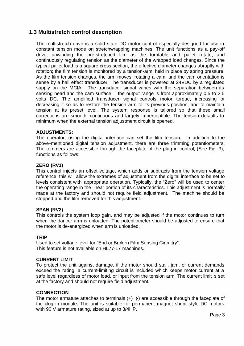
1.3 Multistretch control description
The multistretch drive is a solid state DC motor control especially designed for use in constant tension mode on stretchwrapping machines. The unit functions as a pay-off drive, unwinding the pre-stretched film as the turntable and pallet rotate, and continuously regulating tension as the diameter of the wrapped load changes. Since the typical pallet load is a square cross section, the effective diameter changes abruptly with rotation; the film tension is monitored by a tension-arm, held in place by spring pressure. As the film tension changes, the arm moves, rotating a cam, and the cam orientation is sense by a hall effect transducer. The transducer is powered at 24VDC by a regulated supply on the MCIA. The transducer signal varies with the separation between its sensing head and the cam surface – the output range is from approximately 0.5 to 3.5 volts DC. The amplified transducer signal controls motor torque, increasing or decreasing it so as to restore the tension arm to its previous position, and to maintain tension at its preset level. The system response is tailored so that these small corrections are smooth, continuous and largely imperceptible. The tension defaults to minimum when the external tension adjustment circuit is opened. ADJUSTMENTS: The operator, using the digital interface can set the film tension. In addition to the above-mentioned digital tension adjustment, there are three trimming potentiometers. The trimmers are accessible through the faceplate of the plug-in control, (See Fig. 3), functions as follows: ZERO (RV1) This control injects an offset voltage, which adds or subtracts from the tension voltage reference; this will allow the extremes of adjustment from the digital interface to be set to levels consistent with appropriate operation. Typically, the “Zero” will be used to center the operating range in the linear portion of its characteristics. This adjustment is normally made at the factory and should not require field adjustment. The machine should be stopped and the film removed for this adjustment. SPAN (RV2) This controls the system loop gain, and may be adjusted if the motor continues to turn when the dancer arm is unloaded. The potentiometer should be adjusted to ensure that the motor is de-energized when arm is unloaded. TRIP Used to set voltage level for “End or Broken Film Sensing Circuitry”. This feature is not available on HL77-17 machines. CURRENT LIMIT To protect the unit against damage, if the motor should stall, jam, or current demands exceed the rating, a current-limiting circuit is included which keeps motor current at a safe level regardless of motor load, or input from the tension arm. The current limit is set at the factory and should not require field adjustment. CONNECTION The motor armature attaches to terminals (+) (-) are accessible through the faceplate of the plug-in module. The unit is suitable for permanent magnet shunt style DC motors with 90 V armature rating, sized at up to 3/4HP.
Page 3
1.4 Turntable control description
The turntable control is a DC motor control designed for the use as a turntable drive of wrapping machines, where long and repeatable acceleration and deceleration times is needed, and remotely selectable pre-set speeds are required. The unit requires a 90 V armature, permanent magnet DC motor as output device. CURRENT LIMIT To protect the unit against damage, if the motor should stall, jam, or current demands exceed the rating, a current-limiting circuit is included which keeps motor current at a safe level regardless of motor load. The current limit is set at the factory and should not require field adjustment. CONNECTION The motor armature attaches to quick disconnect terminals (+) (-) are accessible through the faceplate of the plug-in module. The unit is suitable for permanent magnet shunt style DC motors with 90 V armature rating, sized at up to 3/4HP.
1.5 Carriage control description
The carriage control is a DC motor control designed to operate in direct or reversing mode at preset speeds defined by the user through the keyboard section. The unit requires a 90 V armature, permanent magnet DC motor as output device. Two relays and a dynamic braking resistor (DBR) are used for motor reversing and braking. The brake resistor is bolted to a card-rack side plate, part of the MBIA. The circuit is equipped with anti-plug protective interlocks. CURRENT LIMIT To protect the unit against damage, if the motor should stall, jam, or current demands exceed the rating, a current-limiting circuit is included which keeps motor current at a safe level regardless of motor load. The current limit is set at the factory and should not require field adjustment. CONNECTION The motor armature attaches to quick-disconnect terminals (+) (-), on the MBIA motherboard. The unit is suitable for permanent magnet shunt style DC motors with 90 V armature rating, sized at up to 3/4HP.
Page 4

SECTION 2 Keyboard Description
The keyboard is used to control and monitor all the parameters of a stretch wrapper machine. It will also be used for in house calibration. See Fig 1. Below is a short description for the purpose of each keypad element.
• START The start keypad is used to start or continue a wrapping cycle.
• E-STOP The stop push-button is used to pause and stop a wrapping cycle before it is completed.
• TURNTABLE JOG The jog keypad is used to jog the turntable manually at a preset speed.
• CARRIAGE RAISE The carriage up keypad is used to move the carriage up manually.
• CARRIAGE LOWER The carriage down keypad is used to move the carriage down manually.
• WRAPS This keypad is used to program the number of top and bottom wraps that the turntable will perform during a wrapping cycle.
• TENSION This keypad will set the tension of the wrapping film.
• CARRIAGE SPEED This keypad is used to set the carriage up and down speed.
• FUNCTION This keypad is used for in house programming and adjustments. Access is limited to authorised personnel by a password code.
• SPIRAL This keypad is used to select between “UP/DOWN” and “UP ONLY” spiral wrapping patterns
• PHOTOCELL This keypad is used to enable and disable the load auto-height photocell.
• VALUE UP and DOWN Arrows Those keypads are used to change the value of parameters displayed on the SSD.
Page 5
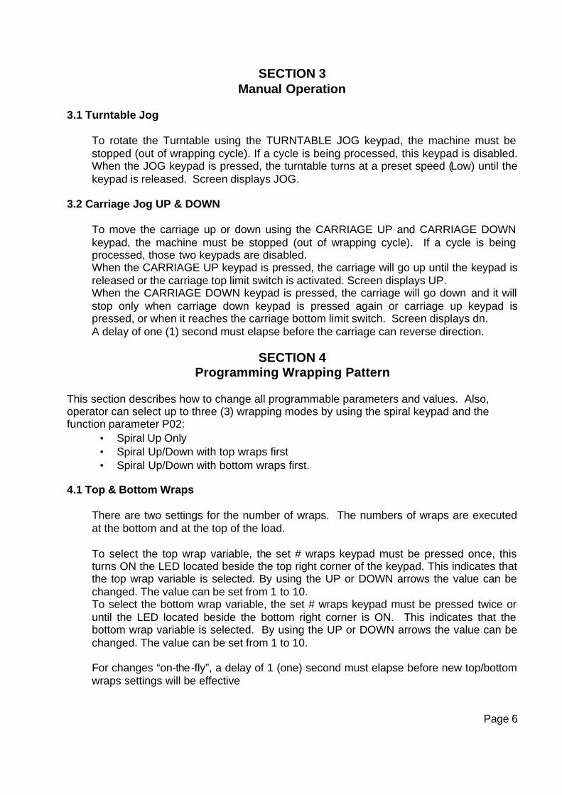
SECTION 3 Manual Operation
3.1 Turntable Jog
To rotate the Turntable using the TURNTABLE JOG keypad, the machine must be stopped (out of wrapping cycle). If a cycle is being processed, this keypad is disabled. When the JOG keypad is pressed, the turntable turns at a preset speed (Low) until the keypad is released. Screen displays JOG.
3.2 Carriage Jog UP & DOWN
To move the carriage up or down using the CARRIAGE UP and CARRIAGE DOWN keypad, the machine must be stopped (out of wrapping cycle). If a cycle is being processed, those two keypads are disabled. When the CARRIAGE UP keypad is pressed, the carriage will go up until the keypad is released or the carriage top limit switch is activated. Screen displays UP. When the CARRIAGE DOWN keypad is pressed, the carriage will go down and it will stop only when carriage down keypad is pressed again or carriage up keypad is pressed, or when it reaches the carriage bottom limit switch. Screen displays dn. A delay of one (1) second must elapse before the carriage can reverse direction.
SECTION 4
Programming Wrapping Pattern This section describes how to change all programmable parameters and values. Also, operator can select up to three (3) wrapping modes by using the spiral keypad and the function parameter P02:
• Spiral Up Only • Spiral Up/Down with top wraps first • Spiral Up/Down with bottom wraps first.
4.1 Top & Bottom Wraps
There are two settings for the number of wraps. The numbers of wraps are executed at the bottom and at the top of the load. To select the top wrap variable, the set # wraps keypad must be pressed once, this turns ON the LED located beside the top right corner of the keypad. This indicates that the top wrap variable is selected. By using the UP or DOWN arrows the value can be changed. The value can be set from 1 to 10. To select the bottom wrap variable, the set # wraps keypad must be pressed twice or until the LED located beside the bottom right corner is ON. This indicates that the bottom wrap variable is selected. By using the UP or DOWN arrows the value can be changed. The value can be set from 1 to 10. For changes “on-the-fly”, a delay of 1 (one) second must elapse before new top/bottom wraps settings will be effective
Page 6

4.2 Film Tension
To select the film tension variable, press the FILM TENSION keypad. The FILM TENSION LED is located at the top right corner of the keypad. Once the keypad is pressed and the LED is ON, the UP and DOWN arrows can be used to change the value. The value may be set from 0 to 100 (0 -100%).
4.3 Carriage UP & DOWN Speed
There are two settings for the carriage speed: the CARRIAGE UP and the CARRIAGE DOWN speeds. By pressing once on the carriage speed keypad, the LED located at the top right corner of the keypad will turn ON. This means that the carriage speed up variable is selected. By using the UP or DOWN keypad arrows the value can be changed. The value will vary from 0 to 100 (0-100%). To select the CARRIAGE DOWN variable, the CARRIAGE SPEED keypad must be pressed twice or until the LED located at the bottom right corner is ON. By using the UP or DOWN keypad arrows the value can be changed. The value will vary from 0 to 100 (0-100%).
4.4 Spiral UP / UP & DOWN
Pressing up only keypad, it will switch between “spiral up only” and “spiral up & down”. When LED is ON, the “spiral up only” mode is selected and the sequence will be:
1. Film carriage wraps bottom of load with selected number of bottom wraps 2. Film carriage moves up until top of load is reached 3. Applies selected number of top wraps 4. Turntable decelerates and stops in home position
When LED is OFF, the “spiral up & down” mode is selected and the sequence will be according to the value of the advanced parameter P02 (see section 6 for setting of P02).
If “top wraps first” is selected (P02=0)
1. Film carriage moves until top of load is reached 2. Applies selected number of top wraps 3. Film carriage moves to the bottom of load 4. Applies selected number of bottom wraps 5. Turntable decelerates and stops in home position
If “bottom wraps first“ is selected (P02=1)
1. Applies selected number of bottom wraps 2. Film carriage moves until top of load is reached 3. Applies selected number of top wraps 4. Film carriage moves to the bottom of load 5. Turntable decelerates and stops in home position
Page 7

4.5 Photo eye
Note: this feature works only when machine is running ... (During Cycle) To automatically detect top of the load (to stop carriage motion up with or without “overlap”) carriage auto-height photo eye must be enabled. The photo eye is enabled or disabled by the photo eye keypad. When enabled, the photo eye goes ON.
4.6 Default Setting
DESCRIPTION DATA RANGE Default Value Top wraps From 1 to10 02 Bottom wraps From 1 to 10 02 Tension From 0 to100 10 Carriage speed up From 0 to100 65 Carriage speed down From 0 to100 65
SECTION 5 Mode of Operation
5.1 Cycle Start
To start new wrapping cycle press green keypad CYCLE START. 5.2 Pause/Stop
Note: this feature works only when machine is running ... (During Cycle) Machine can be put in a pause state by pressing the E-STOP button ONCE. Machine keeps the present machine cycle parameter values. Screen will display PAU/FLT or PAU depends on E-Stop button position. Machine will remain in pause state until either:
• START keypad has been pressed. Cycle will continue uninterrupted and screen displays the present machine cycle state.
• STOP button has been pressed twice. Cycle will be aborted, indicating that reset has
been performed and screen will display end. Machine is ready for a new wrapping cycle.
Page 8

SECTION 6 Advanced parameters setting
6.1 Parameter Description
PARAMETER DESCRIPTION DATA RANGE DEFAULT P00 Table Speed High From 0 to 100 78 P01 Table Speed Low From 0 to100 06 P02 Top Bottom Wraps First 0 “ Top Wraps First” or 1 “Bottom Wraps First 0 P03 Not Implemented 0 N/A P04 Table Acceleration Time From 0 to100 10 P05 Table Deceleration Time From 0 to 100 10 P06 Table Pulses Per Rotation 96 P07 Not Implemented 0 N/A P08 Not Implemented 0 N/A P09 Not Implemented 0 N/A P10 Not Implemented 0 N/A P11 Exit When selected we exit Function N/A P12 Get Default When Selected we load Default settings N/A 6.2 Accessing parameters
The select function keypad is used to access advanced parameters settings - as describe in table above. Editing these parameters is permitted only when machine is stopped (out of wrapping cycle). Parameters are not available to the operator; they are protected by a 3-digit pass-code (range from 0 to 250). (For password contact your local distributor). When the select function keypad is depressed, the screen displays PSU (user to enter the password). Using the up and down arrows, the correct 3-digit number code must be entered: when it is entered, the select function keypad must be pressed again and the Function LED will start flashing. The advanced parameter has now been accessed. The parameters are identified by a 3-digit code Pxx where xx is a number between 0 -12. Use the up and down arrows to select a parameter. Once the desired parameter has been selected, press the select function button to toggle between the data and the parameter mode. The Up or Down arrows are used to set the desired value (Data) in the Parameter. Once the value is entered, press the select function keypad again to return to the Select Parameter Mode. While Function Parameters are being edited, the Function LED continuously flashes.
6.3 Parameter Saving
The new values are saved when one of the following procedures is applied: • Jog keypad is pressed • Start keypad is pressed • 30 Seconds without any editing activity (no button pressed).
Page 9

6.4 Get Default Settings
Note: this feature works only when machine is stopped ... (Off Cycle) The user can load a specific default setting of parameters by selecting the function parameter P12. Screen will display DEF. The actual machine settings will be overwritten by a set of default values.
6.5 Exit Function
There are two ways to exit the Function Editing Mode: • Once the editing is complete, press the select function keypad again and choose parameter P11 to exit function editing and return to the operator’s menu. New values will be saved at this time. • If 30 seconds elapse without any editing activity, the program exits the function-editing mode, saves the new values and returns to the operator’s menu.
SECTION 7 Display Screen
7.1 Display Contents
Screen Description End Machine is stopped PAU/FLT Machine in a pause (out of wrapping cycle) with E-STOP depressed
(display will flash). PAU Machine in a pause with E-STOP released. UP Carriage is moving up dn Carriage is moving down PSU Asks user to enter password code to have access to function
parameters edition. DEF While getting default settings and then it displays the present machine
state. eXt While exiting function parameters edition then it displays present
machine state. Pxx When selecting function parameter xxx When editing machine parameters values JOG When jogging the turntable manually
7.2 Display Refresh
Display is refreshed every 3 seconds. When finished editing, it displays the present machine cycle state (PAU for a pause state, END when machine stopped, UP when Carriage moving up, DN while carriage moving down, number of wraps when wrapping).
Page 10

SECTION 8 Maintenance
8.1 Replacing Sub Assemblies
The connections are mainly plug-in, and wrong connection is unlikely, but special attention should be taken to the configuration when removing items. Repair and replacement should only be done by experienced personnel who are aware of the dangers of working on line-operated equipment. Power must be turn off when changing sub-assemblies, and the technician should dissipate any static charges before handling parts, by touching the grounded cabinet. The MBIA can be removed by removing the four screws securing the chassis to the back plate. Unplug the various terminal connectors, the ribbon connector, the disconnect terminals and remove the unit. Removing two securing screws and then unplugging can individually replace the THREE DC DRIVE controls. An on-board AGC-8 fuse, accessible when the drive control has been unplugged, protects each control. The microprocessor board on the inside of the cabinet door connects by ribbon cable to the MCIA. The ribbon cable should be unplugged before removing the PCB. The microprocessor board is held in place by six #6 nylon nuts. When these nuts are removed, the microprocessor board can be unplugged from the keyboard/display by gently pulling it out. The keyboard display can be removed by releasing the six nylon hex threaded spacers.
8.2 Board-Level Maintenance
In most cases, repair is beyond the scope of field service, without special equipment. However, the motherboard does contain replaceable items – the control fuse (AGC ½ Amp), and the carriage reversing relays.
SECTION 9
Trouble-Shooting
When operating the machine manually, if the carriage can be raised/lowered, it is assumed the carriage section to be functional. If the turntable can be jogged, this section too should be functional. If the film control responds to a light pull on the film, feeding freely, this section is also functional. If only one of these functions does not respond, the appropriate drive module can be unplugged and its fuse can be examined. If the fuse is blown, it should be replaced only with the recommended type and value. If the fuse immediately blows again, it is probably because one or more of the power devices is shorted. The proper devices should be used for replacement. If there are problems reversing the carriage drive, and/or the relays show signs of burned contacts, these should be replaced. They are plug-in devices. If the Display is not lit, displays anomalous characters, or does not respond to keyboard input, the problem could be a problem with the Microprocessor PCB.
Page 11

There is also the possibility of problems with external limit switches, pulse pickups sensor, or the Hall effect device. This should be apparent by problems with particular functions, i.e.: failure to respond to limits. Operating the devices manually and measuring the resistance of the switches or the output of the pulse pickup sensor could assist in diagnosis. The microprocessor PCB is equipped with six monitoring LEDs, which should assist in verifying whether signals from external devices are being received and detected by the 755 system (Fig 2.). These are (from the top):
• Pulse pickup (turntable momentary position sensor) – an inductive sensor
beneath the turntable detects the passage of drive gear teeth as a means of monitoring turntable position. Each tooth produces a pulse input to the microprocessor. An LED flashes with each pulse. The device connects to the 3 position green plug-in terminal strip (TB3) on the left side of the MCIA. Proper input can be observed as rapid flashing of the LED
• Carriage run – light turns off when the carriage drive is energized. • Carriage down limit – light turns off when the down limit switch is operated • Carriage up Limit – light turns off when the up limit switch is operated • Turntable run – light turns on when the turntable drive is energized
The hall effect device calibration is described on page 3. If there is no input voltage measure from the hall effect device while moving the multistretch dancer arm, replace the hall effect device to see if the problem is related to the sensor. This can be monitored at terminals 1 (signal) and 23 (common) of the terminal interface (TB 4 - green plug-in terminals at bottom left of MCIA - see Fig. 3). The supply 24VDC can be observed at terminal 24.
SECTION 10 Spares Parts
The three principal sub-assemblies to control the operation. To ensure continuity of operation, spares parts should be obtainable:
• The Keyboard display (type 755.1) • The Microprocessor Board (type 755.2) • The Motor Control Interface Assembly which comprises:
• Mother Board Assembly (type 755.3) • Multistretch Drive (type 755.4) • Carriage Drive (type 755.5) • Turntable Drive (type 755.6)
• Fuse Buss AGC 8 • Fuse Buss AGC 1/2 • Relay P&B K10P-11A15-120 • Power switch knob LFS 2-N-6-175 • Power switch body LE 2-20-1752 • Hall effect transducer IB05T • Top & bottom limit switch ZCK-J404H7
Page 12
LOADING THE FILM The film roll can be loaded on the carriage mandrel from either end of the roll. When using tacky film, please verify that the inward tacky surface of the film is inward on the load. 1. Disconnect power (turn off power switch). 2. Swing up the top mandrel spool. 3. Put the roll of film on the bottom mandrel. 4. Install the top mandrel on top of the roll to prevent upward movement. 5. Pull the handle marked PULL TO OPEN to open film distributor cradle. 6. Pass the roped tail of the film through opening (as shown on the film quick threading pattern DWG. # 418180 Fig.1). 7. Close the film distributor cradle by pushing bar marked PUSH TO CLOSE. 8. When the film feeding is completed (fig. 2) – turn the power switch on. 9. Peel off the first few winds of the film (multistrech will run due to displacement of the dancer roller) and fix the film end onto the load.
The system is now ready to begin the first wrapping cycle.


PROXIMITY SENSOR ADJUSTMENT
Occasionally the Feed Back Proximity Sensor may need some adjustment. The position of the feed back proximity sensor against the cam is shown on drawing # 419139. Adjustment instructions: - Remove the carriage cover - Unbolt the two nuts holding the proximity switch - item # 1 - Turn the Proximity sensor - (item # 2) to create the gap between the cam and the front side of proximity sensor about 1/8 “ - Tighten on the nuts securing the Proximity Sensor
- Turning the trim pot SPAN adjust the moment when motor starts to turn when dancer roller moved from its home position up to 1 1/2”.

MACHINE MAINTENANCE All general information about machine maintenance is based on normal machine working conditions: indoor, moderate dust and low moisture environment, and maximum rotation of 32 RPM of turntable/rotary arm. They should be regarded as guidelines, reviewed and corrected according to requirements of actual use and conditions. MOTOR MAINTENANCE An occasional inspection of the brushes should be made in order to establish a wear rate. Replacement brushes should be installed before old brushes wear to 9/16” long, measured on the long side. After replacing brushes run the motor near rated speed for at least l/2 hour with no load to seat the new brushes. Failure to properly seat the new brushes may cause commutator damage and rapid wear of the new brushes. If the commutator becomes rough, scored or out of shape, a competent motor shop should disassemble it and resurface the commutator. With every third brush change, have a competent motor shop resurface the commutator and blow the carbon dust out of the motor. REDUCER OIL CHANGE All external cap screws and plugs on the reducing transmission should be checked for tightness after the first week. It is recommended to change the oil every six months or at least 1800 hours of operation, whichever comes first. When adding or changing oil, the transmission should never be filled above the oil level mark indicated, because leakage and overheating may occur. Below is the list of the type of lubricant that should be used. List of recommended reducer oils Manufacturer Lubricant American Oil Co.. American Cyl Oil no: 196-L Cities Service Oil Co. Citgo Cyl Oil 100-5 Gulf Oil Corp. Gulf Senate 155 Mobil Oil Corp. Mobil 600 W Suer-r Cyl. Oil Philips Oil Corp. Andes S 180 Texaco Inc. 624 + 650T Cyl.Oil Shell Oil Co. Velvata Oil J82 Union Oil of Cal. Red Line Worm Gear Lube 140 RING BEARING MAINTENANCE (when applicable) The ring bearing (located under the turntable) should be re-lubricated internally and externally. Internally: by injecting grease into all the lubrication nipples in succession until a collar of fresh grease appears around the perimeter of the ring. The re-lubrication interval suggested for these bearings, used in Stretch Wrapping Machinery is 750 hours, with a maximum period of 6 months. The lubricant should be fresh and applied in sufficient quantities to make sure all surfaces are lubricated.

Externally: by lubricating and wiping the chain drive with oily cloth. The frequency of lubrication depends on entirely upon the usage of the machine and environment in which the machine is placed (dust, moisture etc.). Machines working under extremely dirty conditions should be lubricated every 400 operating hours but at minimum, every 2 months. Longer lubrication intervals may occur only when machine is working under very clean and dry conditions but should be not be longer than 6 months. List of recommended lubricants for the ring bearing lubrication
Manufacturer Lubricant BP Energrease LS2 Castrol Speeroll AP2 Esso Beacon 2 Gulf Crown Grease 2 Mobil Mobilus 2 Shell Avania Grease R2 Texaco Glissando FT 2 Valvoline LB-2
TOWER RACEWAYS MAINTENANCE The film distributor (carriage) is sliding on the plastic guides attached behind its back plate. The section of the tower on which the plastic guides move (raceways) should be cleaned and re-greased approximately every 600 hours of machine operation. NOTICE: If the machine works in a dusty and corrosive environment, the raceways should be re-greased more often (at least every 100 hours). CHAIN MAINTENANCE To clean the chain, wipe it with an oily cloth every month. When machine is working in a dusty and damp environment, it may be necessary to repeat the cleaning operation more often. As the chain lubricants please use the most common chain lubricants on the market. With time, the chain will tend to stretch. A loose chain should be tightened at the chain tensioner, or by moving the reducer on its mounting plate. NOTICE: Chain tension first adjustment must be done after the first two weeks of machine usage. PNEUMATIC SYSTEM MAINTENANCE (when applicable) The air supply system must be checked weekly and must be free from the moisture. In cold environments, it may be necessary to drain the air supply system daily. CAM FOLLOWER MAINTENANCE (when applicable) The cam followers have deep grease pockets and do not need frequent relubrication. The portion of the tower on which the cam followers run, should be cleaned and regreased every 300 hours of operation. If the machine operates in a dusty or corrosive environment the tower should be relubricated more often.

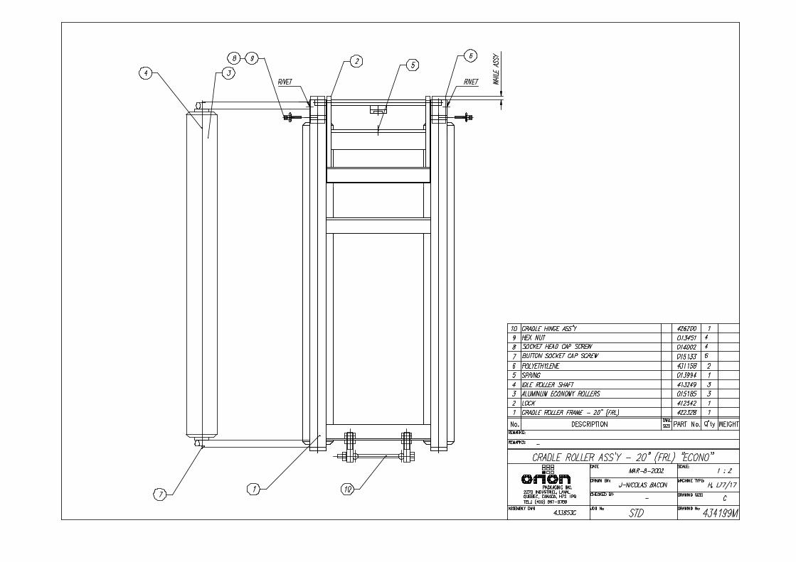
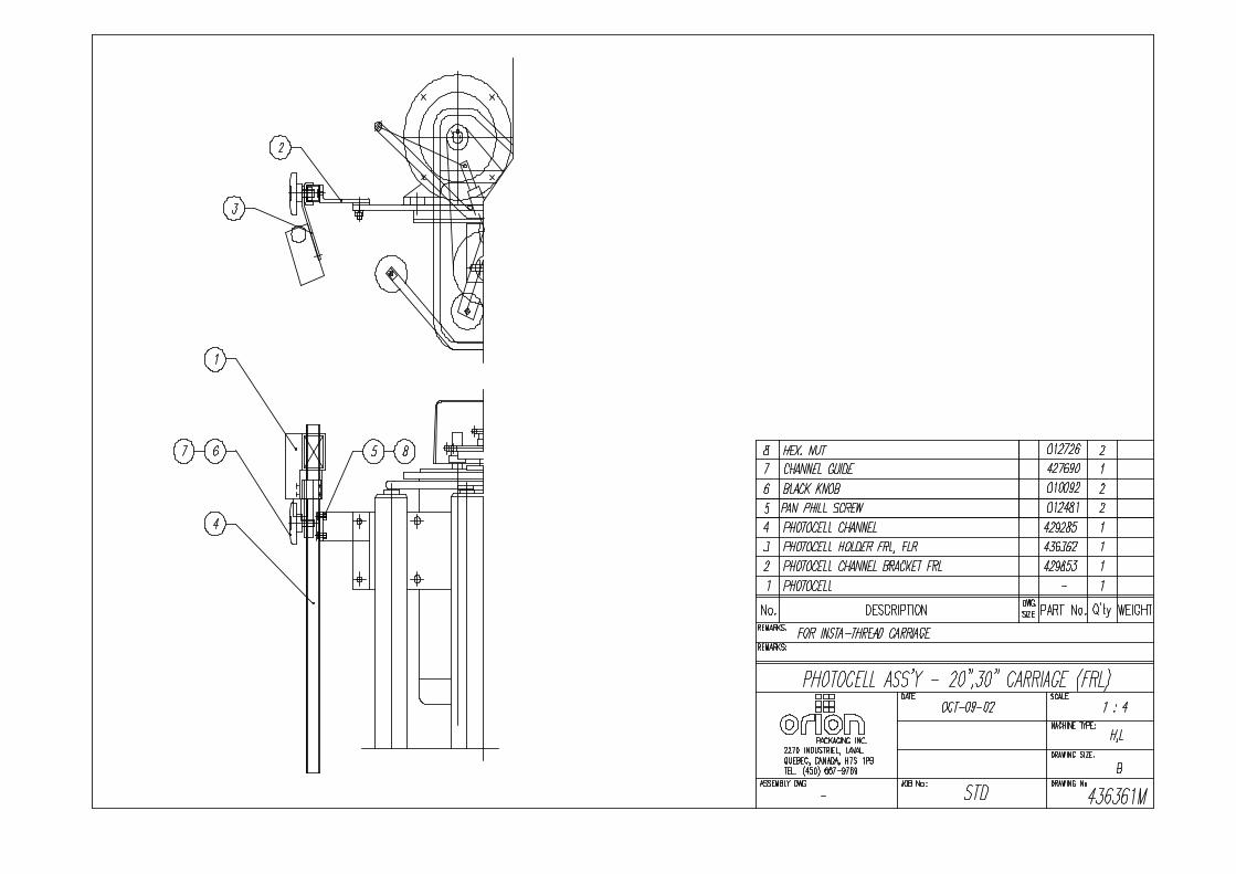
SEMI-AUTOMATIC STANDARD ASSEMBLY
PART LIST
Note : * Quantity listed in order of part number
** The names given to the parts are generic


APPENDIX