model h66 -17 serial # 2004-8899999 - orionsupport.orionpackaging.com/pdf_manuals/h66-17-en.pdf ·...
TRANSCRIPT
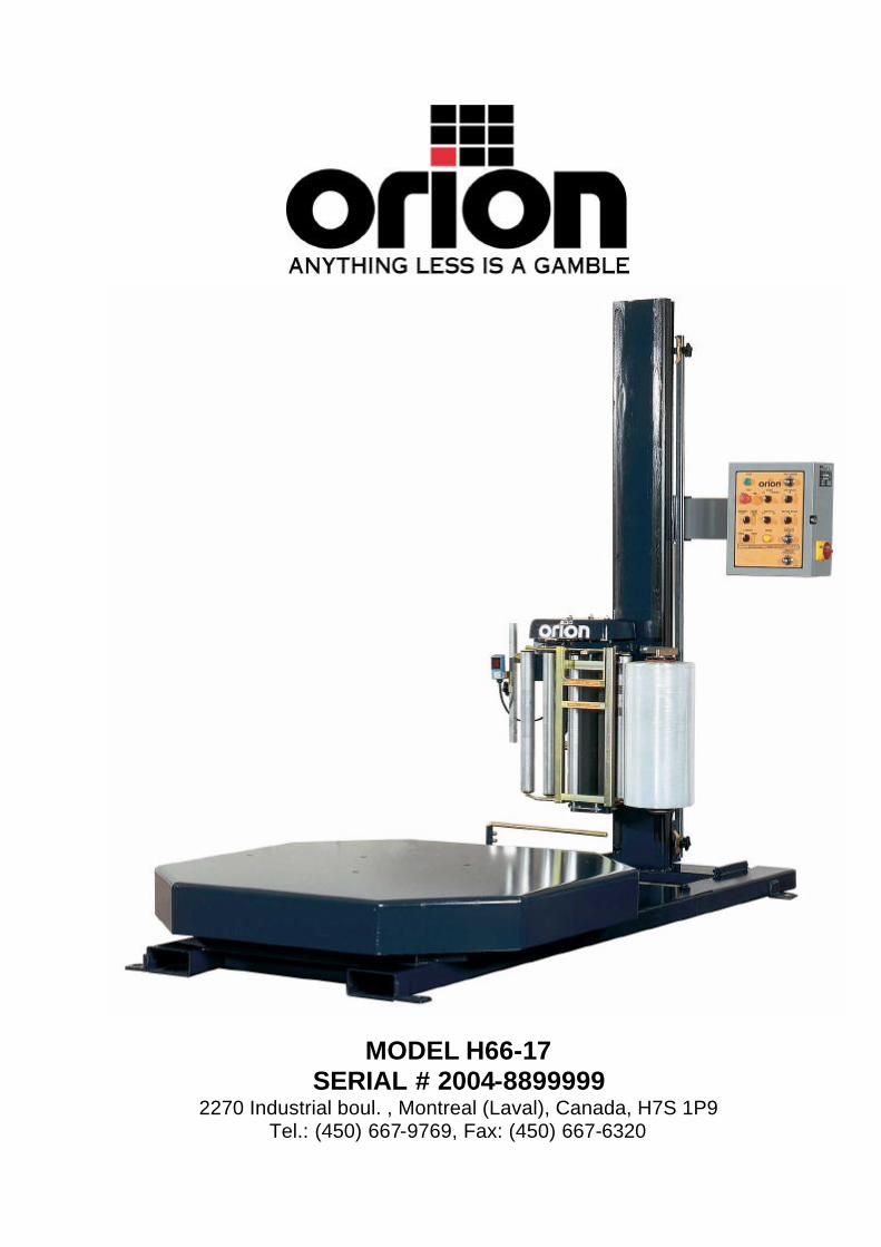
MODEL H66-17 SERIAL # 2004-8899999
2270 Industrial boul. , Montreal (Laval), Canada, H7S 1P9 Tel.: (450) 667-9769, Fax: (450) 667-6320
INSTRUCTION MANUAL
FOR ALL INQUIRIES PLEASE CONTACT
OUR LOCAL DISTRIBUTOR
FOR NORTH AMERICA ONLY 1-800-333-6556
Thank you for choosing ORION stretch-wrapping equipment. It is a wise choice, which will benefit your company now and in the future. ORION uses a unique combination of functional, rugged steel structure and sophisticated control systems to offer equipment high in durability and low in maintenance requirements. Our advance control systems mean that Orion equipment can be operated safely and efficiently without the need for special operator expertise. Please read this manual carefully and keep it handy. Following these simple operating instructions will insure the safe and efficient performance of this machine while simple maintenance procedures will guarantee a long and productive life of the equipment.
Notice: Our manual covers standard features of the machine. Certain options may not be fully covered due to their unique application. In order to acquire more information about custom made features of your machine and to provide quicker service, the following information is required when making an inquiry: 1)Model 2)Serial Number 3)Subassembly ( see PART LIST ) SAFETY: ORION'S stretch wrappers should be operated with caution and common sense as any other industrial equipment. To prevent injury and/or electrical shocks, careful operation of the machine and awareness of its many automatic functions is required. NOTE: All electrical power and compressed air must to be disconnected prior to all inspection, maintenance or repair work.
ORION PACKAGING INC.
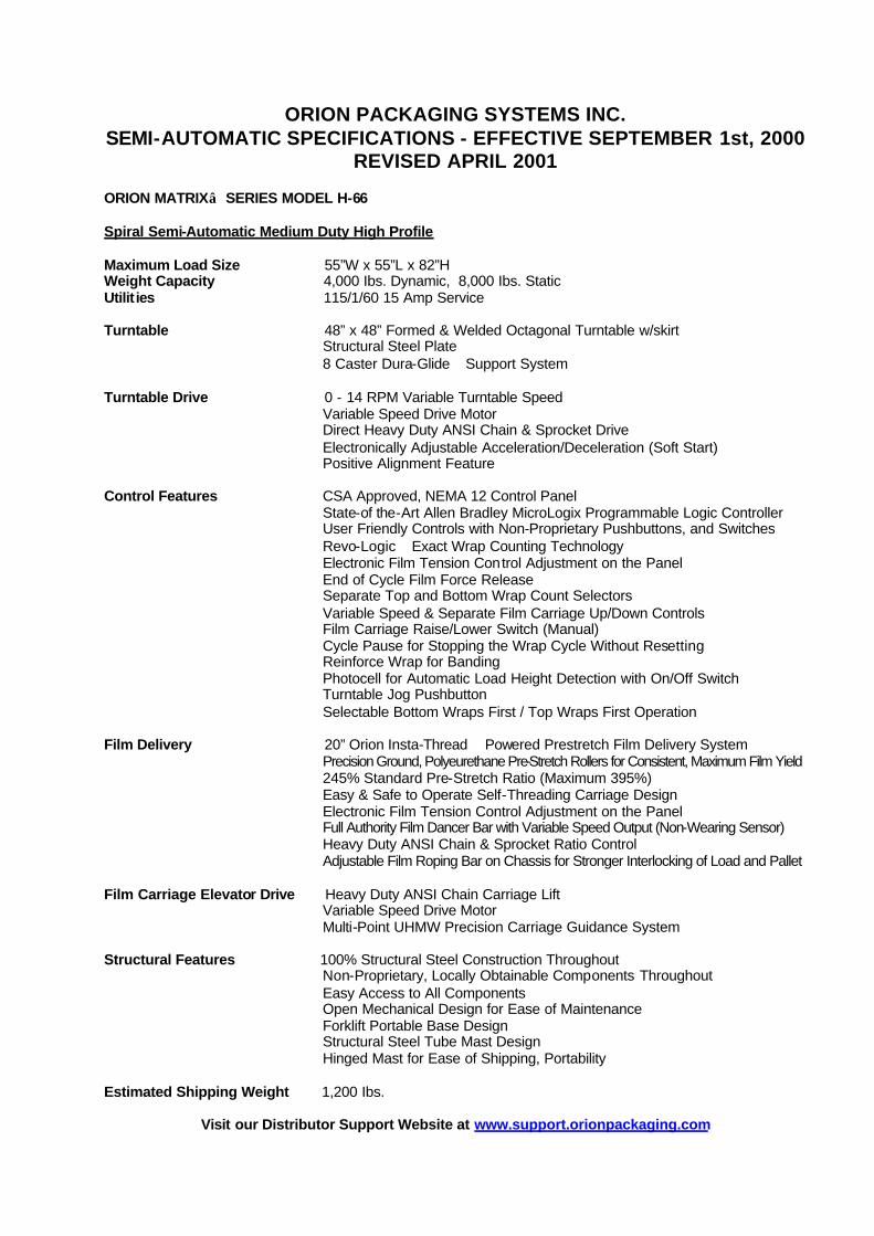
ORION PACKAGING SYSTEMS INC. SEMI-AUTOMATIC SPECIFICATIONS - EFFECTIVE SEPTEMBER 1st, 2000
REVISED APRIL 2001
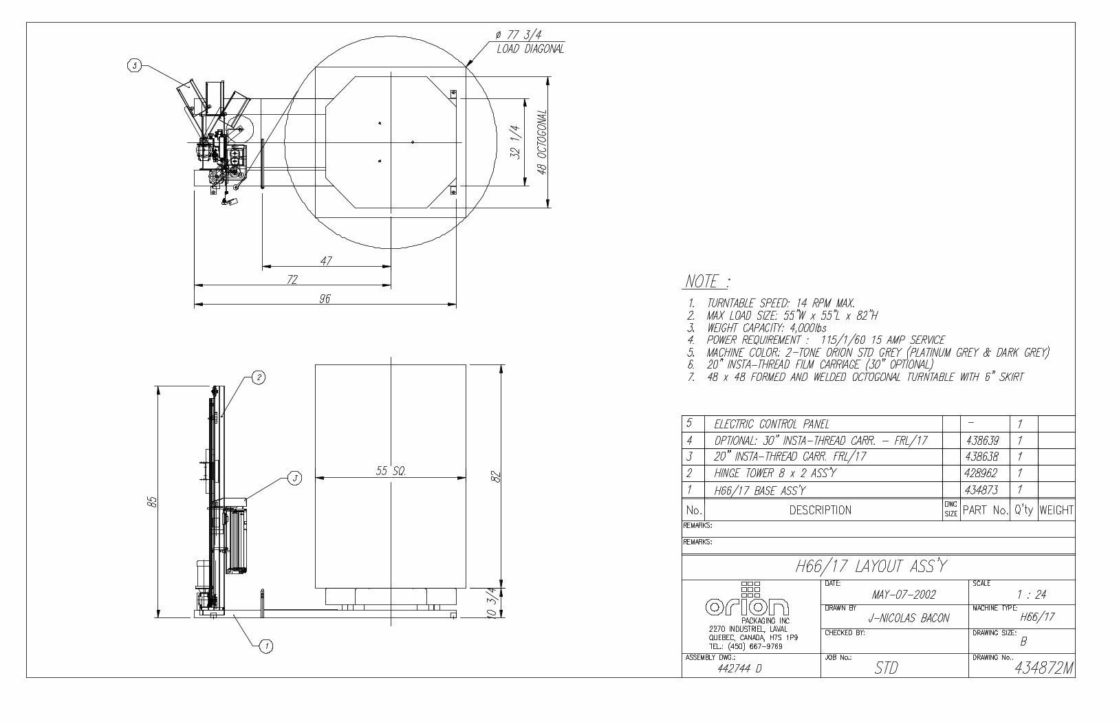
ORION MATRIX SERIES MODEL H-66
Spiral Semi-Automatic Medium Duty High Profile Maximum Load Size 55”W x 55”L x 82”H Weight Capacity 4,000 Ibs. Dynamic, 8,000 Ibs. Static Utilit ies 115/1/60 15 Amp Service Turntable 48” x 48” Formed & Welded Octagonal Turntable w/skirt
Structural Steel Plate 8 Caster Dura-Glide Support System
Turntable Drive 0 - 14 RPM Variable Turntable Speed
Variable Speed Drive Motor Direct Heavy Duty ANSI Chain & Sprocket Drive Electronically Adjustable Acceleration/Deceleration (Soft Start) Positive Alignment Feature
Control Features CSA Approved, NEMA 12 Control Panel
State-of the-Art Allen Bradley MicroLogix Programmable Logic Controller User Friendly Controls with Non-Proprietary Pushbuttons, and Switches Revo-Logic Exact Wrap Counting Technology Electronic Film Tension Control Adjustment on the Panel End of Cycle Film Force Release Separate Top and Bottom Wrap Count Selectors Variable Speed & Separate Film Carriage Up/Down Controls Film Carriage Raise/Lower Switch (Manual) Cycle Pause for Stopping the Wrap Cycle Without Resetting Reinforce Wrap for Banding Photocell for Automatic Load Height Detection with On/Off Switch Turntable Jog Pushbutton Selectable Bottom Wraps First / Top Wraps First Operation
Film Delivery 20” Orion Insta-Thread Powered Prestretch Film Delivery System
Precision Ground, Polyeurethane Pre-Stretch Rollers for Consistent, Maximum Film Yield 245% Standard Pre-Stretch Ratio (Maximum 395%) Easy & Safe to Operate Self-Threading Carriage Design Electronic Film Tension Control Adjustment on the Panel Full Authority Film Dancer Bar with Variable Speed Output (Non-Wearing Sensor) Heavy Duty ANSI Chain & Sprocket Ratio Control Adjustable Film Roping Bar on Chassis for Stronger Interlocking of Load and Pallet
Film Carriage Elevator Drive Heavy Duty ANSI Chain Carriage Lift Variable Speed Drive Motor Multi-Point UHMW Precision Carriage Guidance System
Structural Features 100% Structural Steel Construction Throughout
Non-Proprietary, Locally Obtainable Components Throughout Easy Access to All Components Open Mechanical Design for Ease of Maintenance Forklift Portable Base Design Structural Steel Tube Mast Design Hinged Mast for Ease of Shipping, Portability
Estimated Shipping Weight 1,200 Ibs.
Visit our Distributor Support Website at www.support.orionpackaging.com
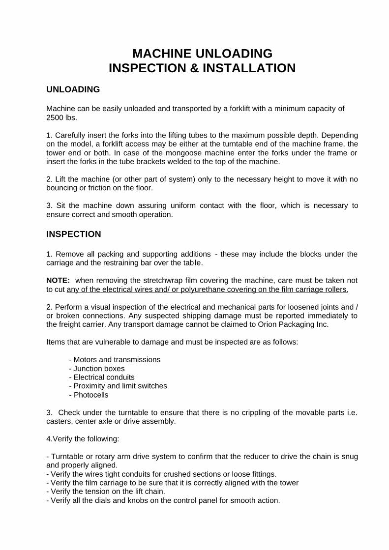
MACHINE UNLOADING INSPECTION & INSTALLATION
UNLOADING Machine can be easily unloaded and transported by a forklift with a minimum capacity of 2500 lbs. 1. Carefully insert the forks into the lifting tubes to the maximum possible depth. Depending on the model, a forklift access may be either at the turntable end of the machine frame, the tower end or both. In case of the mongoose machine enter the forks under the frame or insert the forks in the tube brackets welded to the top of the machine. 2. Lift the machine (or other part of system) only to the necessary height to move it with no bouncing or friction on the floor. 3. Sit the machine down assuring uniform contact with the floor, which is necessary to ensure correct and smooth operation. INSPECTION 1. Remove all packing and supporting additions - these may include the blocks under the carriage and the restraining bar over the table. NOTE: when removing the stretchwrap film covering the machine, care must be taken not to cut any of the electrical wires and/ or polyurethane covering on the film carriage rollers. 2. Perform a visual inspection of the electrical and mechanical parts for loosened joints and / or broken connections. Any suspected shipping damage must be reported immediately to the freight carrier. Any transport damage cannot be claimed to Orion Packaging Inc. Items that are vulnerable to damage and must be inspected are as follows:
- Motors and transmissions - Junction boxes - Electrical conduits - Proximity and limit switches - Photocells
3. Check under the turntable to ensure that there is no crippling of the movable parts i.e. casters, center axle or drive assembly. 4.Verify the following: - Turntable or rotary arm drive system to confirm that the reducer to drive the chain is snug and properly aligned. - Verify the wires tight conduits for crushed sections or loose fittings. - Verify the film carriage to be sure that it is correctly aligned with the tower - Verify the tension on the lift chain. - Verify all the dials and knobs on the control panel for smooth action.
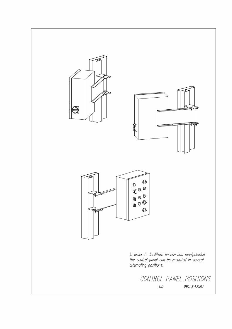
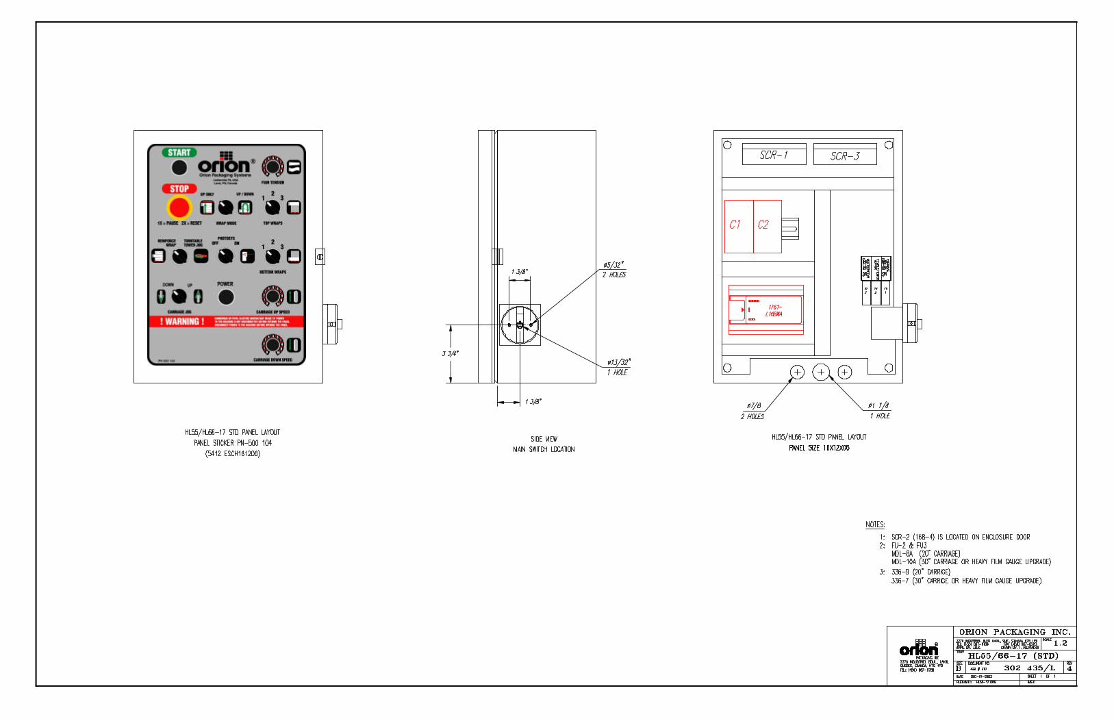
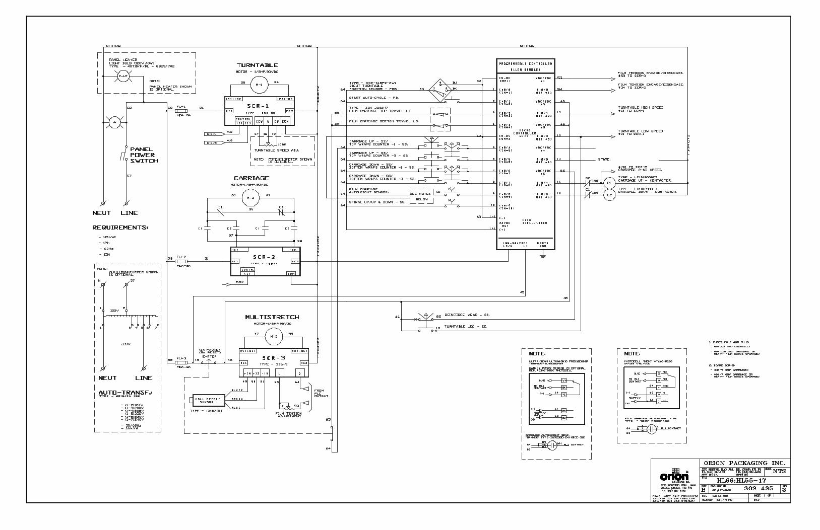
MACHINE INSTALLATION After the visual inspection has been completed, the electrical power and the compressed air shall be connected as specified on the diagrams supplied with the machine. An electrical diagram is provided with each machine in the envelope attached to the panel box. ASSEMBLY PROCEDURE The structural frames of the machine have to be installed on a leveled floor. Locate the main wrapper section into its final position, keeping the tower assembly* away from any traffic. The wrapper mainframe section must be bolted to the floor by the 1/2” concrete floor anchors (leg & shield or expandable type). Any wiring that has been disconnected to facilitate transport is marked with a number located on the junction box to which the wiring must be reconnected. Any wire run that appears too short or long may indicate that the position of the mechanical components is incorrect. Verify the status of all assemblies before proceeding. * The tower deviation from vertical must not exceed 1/4” on the distance of 10 feet (angle: 0 degrees 6’). CONTROL PANEL In the case of the free standing panel (console) place it adjacent to the system and anchor firmly to the floor. Connect the liquid tight (rigid conduit) to the main junction box located on the wrapper main frame next to the tower.
MACHINE OPERATION
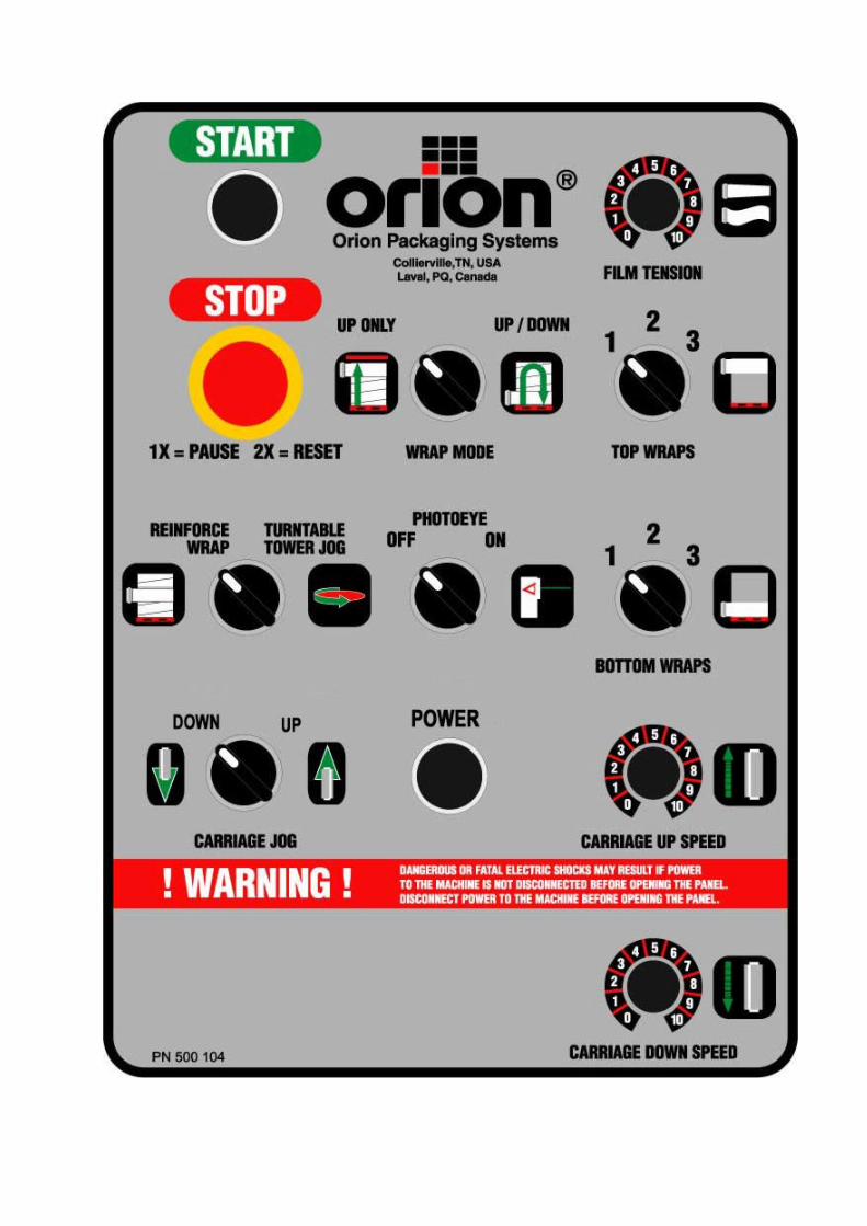
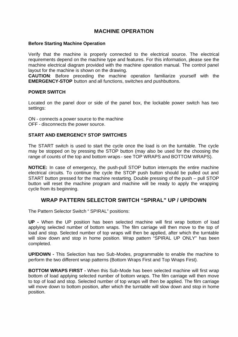
Before Starting Machine Operation Verify that the machine is properly connected to the electrical source. The electrical requirements depend on the machine type and features. For this information, please see the machine electrical diagram provided with the machine operation manual. The control panel layout for the machine is shown on the drawing. CAUTION: Before preceding the machine operation familiarize yourself with the EMERGENCY-STOP button and all functions, switches and pushbuttons. POWER SWITCH Located on the panel door or side of the panel box, the lockable power switch has two settings: ON - connects a power source to the machine OFF - disconnects the power source. START AND EMERGENCY STOP SWITCHES The START switch is used to start the cycle once the load is on the turntable. The cycle may be stopped on by pressing the STOP button (may also be used for the choosing the range of counts of the top and bottom wraps - see TOP WRAPS and BOTTOM WRAPS). NOTICE: In case of emergency, the push-pull STOP button interrupts the entire machine electrical circuits. To continue the cycle the STOP push button should be pulled out and START button pressed for the machine restarting. Double pressing of the push – pull STOP button will reset the machine program and machine will be ready to apply the wrapping cycle from its beginning.
WRAP PATTERN SELECTOR SWITCH “SPIRAL” UP / UP/DOWN
The Pattern Selector Switch “ SPIRAL” positions: UP - When the UP position has been selected machine will first wrap bottom of load applying selected number of bottom wraps. The film carriage will then move to the top of load and stop. Selected number of top wraps will then be applied, after which the turntable will slow down and stop in home position. Wrap pattern “SPIRAL UP ONLY” has been completed. UP/DOWN - This Selection has two Sub-Modes, programmable to enable the machine to perform the two different wrap patterns (Bottom Wraps First and Top Wraps First). BOTTOM WRAPS FIRST - When this Sub-Mode has been selected machine will first wrap bottom of load applying selected number of bottom wraps. The film carriage will then move to top of load and stop. Selected number of top wraps will then be applied. The film carriage will move down to bottom position, after which the turntable will slow down and stop in home position.
TOP WRAPS FIRST - When this Sub-Mode has been selected film carriage will move to top of load and stop. Selected number of top wraps will be applied. The film carriage will then move to bottom of the load and stop. Selected number of bottom wraps will then be applied. The film carriage will be in bottom position; turntable will slow down and stop in home position. Machine is shipped pre-programmed in TOP WRAPS FIRST Sub-Mode, in order to change Sub-Mode from TOP WRAPS FIRST to BOTTOM WRAPS FIRST see instructions below. Before proceeding ensure that machine is in MANUAL, STANDBY MODE (machine is powered on and all machine manual functions are enabled)
- Press the STOP (Red) Button - To Re-program machine to BOTTOM WRAPS FIRST Sub-Mode, switch and hold “Carriage Raise/Lower” Selector Switch in LOWER position and maintain for Approximately 12 seconds. - Pull the STOP (Red) push-button out. - Perform standard machine reset procedure by double push-pull operation of the red Mushroom stop button. - At this point machine is ready and BOTTOM WRAPS FlRST Sub-Mode is now Activated.
To Re-program machine to TOP WRAPS FIRST Sub-Mode follow procedures above, with the exception of step 2. Switch and hold ‘Carriage Raise/Lower” Selector Switch in RAISE position. At this point machine is ready and TOP WRAPS FIRST Sub--Mode is now activated. CARRIAGE CONTROL SWITCH The CARRIAGE CONTROL switch is a three-position switch with the following settings: RAISE - raises the carriage until the top limit switch on the tower is activated. LOWER - lowers the carriage until the bottom limit switch on the tower is activated. The switch is normally positioned in the middle where the carriage remains stationary. Turning the switch to the RAISE or LOWER will activate the carriage to move in the respective direction. TURNTABLE JOG & REINFORCE WRAP The turntable jog switch will rotate the turntable low speed when the switch positioned on the TOWER / TURNTABLE JOG. When the switch is released, the turntable (rotary tower) will stop. The switch is inoperative during the wrap cycle. When the same switch is positioned on the REINFORCE WRAP the carriage will be stationary until the switch is released. PHOTOCELL ON/OFF SWITCH The photocell switch has two settings: ON - when turned ON, the photocell instructs the carriage to stop and begin the top wrap sequence once the top of the load is reached. The carriage will al ways stop at the top of the load regardless of its height. The photoswitch position on the track can be adjusted in order to make the carriage pass the top of the load and overlap the top. OFF - when turned OFF, the photocell is inoperative and the carriage will stop when the top limit switch has been activated.
FILM TENSION Film tension may be adjusted using the film tension control knob. It has a range of tension from 0 to 10 (0 to 4 the low range, 4 to 8 the most useful range for most of the films used by our customers, 8 to 10 as a very high range which may break some films). CARRIAGE SPEED The carriage speed potentiometer control can be used to control the amount of overlap the film will have during the wrap. The potentiometer has settings from 0 to 10, the higher settings being the fastest. High settings mean less film overlap because of faster carriage speed and low settings mean more film overlap because of lower carriage speed. TOP WRAPS 1,2,3...9 Three-position switch controls the number of wraps that may be applied on the top of the load. The machine is preset RANGE # 1 (top wraps: 1 or 2 or 3). To change the values of wrap see TOP & BOTTOM WRAP COUNTS CHANGE. BOTTOM WRAPS 1,2,3...9 Three-position switch controls the number of wraps that may be applied on the bottom of the load. The machine is preset with RANGE # 1 (bottom wraps: 1 or 2 or 3) which may be applied. To change the values of wrap see TOP & BOTTOM WRAP COUNTS CHANGE. TOP & BOTTOM WRAP COUNTS CHANGE The Top & Bottom Wrap Selector Switches have three (3) ranges of wrap counts and operate independently of each other. Range #1 Wrap values of 1 - 2 - 3 Range #2 Wrap values of 4 - 5 - 6 Range #3 Wrap values of 7 - 8 – 9 For the selection of any of these ranges for top and bottom wraps please do as follows: Before proceeding ensure that machine is in MANUAL, STANDBY MODE (machine is powered on and all machine manual functions are enabled) Press the STOP (red) Button Set the Top and Bottom wrap count selector switch to the position corresponding with the desired count range. 1 = Range #1 2 = Range #2 3 = Range #3
Press the START (Green) pushbutton and maintain for approximately 12 seconds. Pull the STOP (Red) pushbutton out. Perform standard machine reset procedure by double push-pull operation of the red mushroom stop button. At this point machine is ready and new preset values are loaded.
MACHINE WRAPPING TEST Notice: It is advisable to test-run the equipment with several pallet loads before attempting to wrap using film. Please position the operator beside the EMERGENCY STOP push button. Start up of the machine (system) may determine the need for the adjustment of:
- Load height stop photoswitch (on the carriage) - Top limit switch position - Bottom limit switch position - Roping bar height adjustment
Before the test procedures adjust the wrapping cycle parameters i.e. top wraps, bottom wraps, height photocell on/off, film tension, carriage speed (those two parameters may be adjusted during the wrapping cycle).
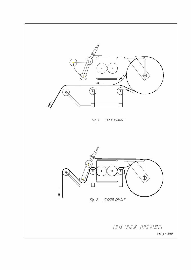
LOADING THE FILM The film roll can be loaded on the carriage mandrel from either end of the roll. When using tacky film, please verify that the inward tacky surface of the film is inward on the load. 1. Disconnect power (turn off power switch). 2. Swing up the top mandrel spool. 3. Put the roll of film on the bottom mandrel. 4. Install the top mandrel on top of the roll to prevent upward movement. 5. Pull the handle marked PULL TO OPEN to open film distributor cradle. 6. Pass the roped tail of the film through opening (as shown on the film quick threading pattern DWG. # 418180 Fig.1). 7. Close the film distributor cradle by pushing bar marked PUSH TO CLOSE. 8. When the film feeding is completed (fig. 2) – turn the power switch on. 9. Peel off the first few winds of the film (multistrech will run due to displacement of the dancer roller) and fix the film end onto the load.
The system is now ready to begin the first wrapping cycle.
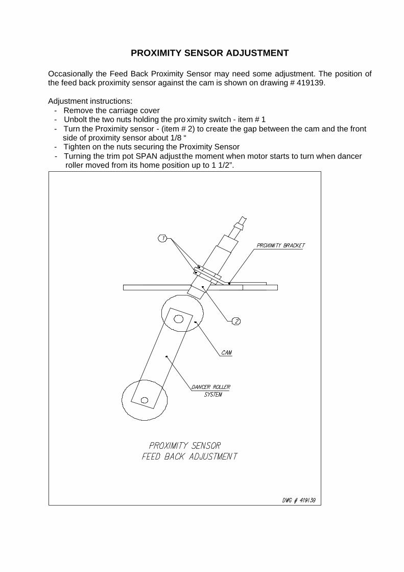
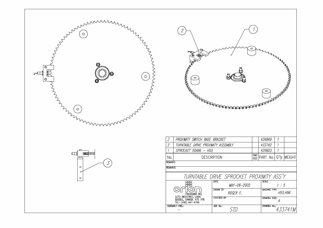
PROXIMITY SENSOR ADJUSTMENT
Occasionally the Feed Back Proximity Sensor may need some adjustment. The position of the feed back proximity sensor against the cam is shown on drawing # 419139. Adjustment instructions: - Remove the carriage cover - Unbolt the two nuts holding the pro ximity switch - item # 1 - Turn the Proximity sensor - (item # 2) to create the gap between the cam and the front side of proximity sensor about 1/8 “ - Tighten on the nuts securing the Proximity Sensor
- Turning the trim pot SPAN adjust the moment when motor starts to turn when dancer roller moved from its home position up to 1 1/2”.
MACHINE MAINTENANCE All general information about machine maintenance is based on normal machine working conditions: indoor, moderate dust and low moisture environment, and maximum rotation of 32 RPM of turntable/rotary arm. They should be regarded as guidelines, reviewed and corrected according to requirements of actual use and conditions. MOTOR MAINTENANCE An occasional inspection of the brushes should be made in order to establish a wear rate. Replacement brushes should be installed before old brushes wear to 9/16” long, measured on the long side. After replacing brushes run the motor near rated speed for at least 1/2 hour with no load to seat the new brushes. Failure to properly seat the new brushes may cause commutator damage and rapid wear of the new brushes. If the commutator becomes rough, scored or out of shape, a competent motor shop should disassemble it and resurface the commutator. With every third brush change, have a competent motor shop resurface the commutator and blow the carbon dust out of the motor. REDUCER OIL CHANGE All external cap screws and plugs on the reducing transmission should be checked for tightness after the first week. It is recommended to change the oil every six months or at least 1800 hours of operation, whichever comes first. When adding or changing oil, the transmission should never be filled above the oil level mark indicated, because leakage and overheating may occur. Below is the list of the type of lubricant that should be used. List of recommended reducer oils Manufacturer Lubricant American Oil Co American Cyl Oil no: 196-L Cities Service Oil Co. Citgo Cyl Oil 100-5 Gulf Oil Corp. Gulf Senate 155 Mobil Oil Corp. Mobil 600 W Suer-r Cyl. Oil Philips Oil Corp. Andes S 180 Texaco Inc. 624 + 650T Cyl.Oil Shell Oil Co. Velvata Oil J82 Union Oil of Cal. Red Line Worm Gear Lube 140 RING BEARING MAINTENANCE (when applicable) The ring bearing (located under the turntable) should be re-lubricated internally and externally. Internally: by injecting grease into all the lubrication nipples in succession until a collar of fresh grease appears around the perimeter of the ring. The re -lubrication interval suggested for these bearings, used in Stretch Wrapping Machinery is 750 hours, with a maximum period of 6 months. The lubricant should be fresh and applied in sufficient quantities to make sure all surfaces are lubricated.
Externally: by lubricating and wiping the chain drive with oily cloth. The frequency of lubrication depends on entirely upon the usage of the machine and environment in which the machine is placed (dust, moisture etc.). Machines working under extremely dirty conditions should be lubricated every 400 operating hours but at minimum, every 2 months. Longer lubricat ion intervals may occur only when machine is working under very clean and dry conditions but should be not be longer than 6 months. List of recommended lubricants for the ring bearing lubrication
Manufacturer Lubricant BP Energrease LS2 Castrol Speeroll AP2 Esso Beacon 2 Gulf Crown Grease 2 Mobil Mobilus 2 Shell Avania Grease R2 Texaco Glissando FT 2 Valvoline LB-2
TOWER RACEWAYS MAINTENANCE The film distributor (carriage) is sliding on the plastic guides attached behind its back plate. The section of the tower on which the plastic guides move (raceways) should be cleaned and re-greased approximately every 600 hours of machine operation. NOTICE: If the machine works in a dusty and corrosive environment, the raceways should be re-greased more often (at least every 100 hours). CHAIN MAINTENANCE To clean the chain, wipe it with an oily cloth every month. When machine is working in a dusty and damp environment, it may be necessary to repeat the cleaning operation more often. As the chain lubricants please use the most common chain lubricants on the market. With time, the chain will tend to stretch. A loose chain should be tightened at the chain tensioner, or by moving the reducer on its mounting plate. NOTICE: Chain tension first adjustment must be done after the first two weeks of machine usage. PNEUMATIC SYSTEM MAINTENANCE (when applicable) The air supply system must be checked weekly and must be free from the moisture. In cold environments, it may be necessary to drain the air supply system daily. CAM FOLLOWER MAINTENANCE (when applicable) The cam followers have deep grease pockets and do not need frequent relubrication. The portion of the tower on which the cam followers run, should be cleaned and regreased every 300 hours of operation. If the machine operates in a dusty or corrosive environment the tower should be relubricated more often.

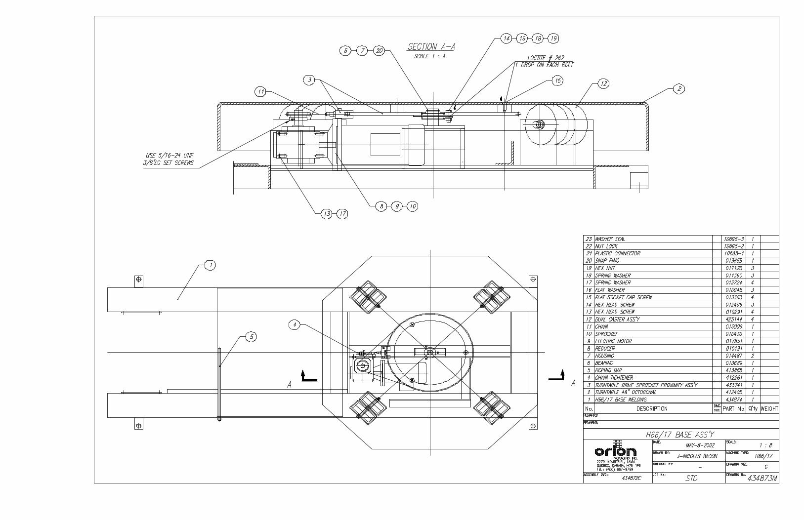
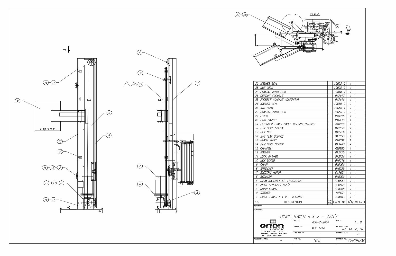
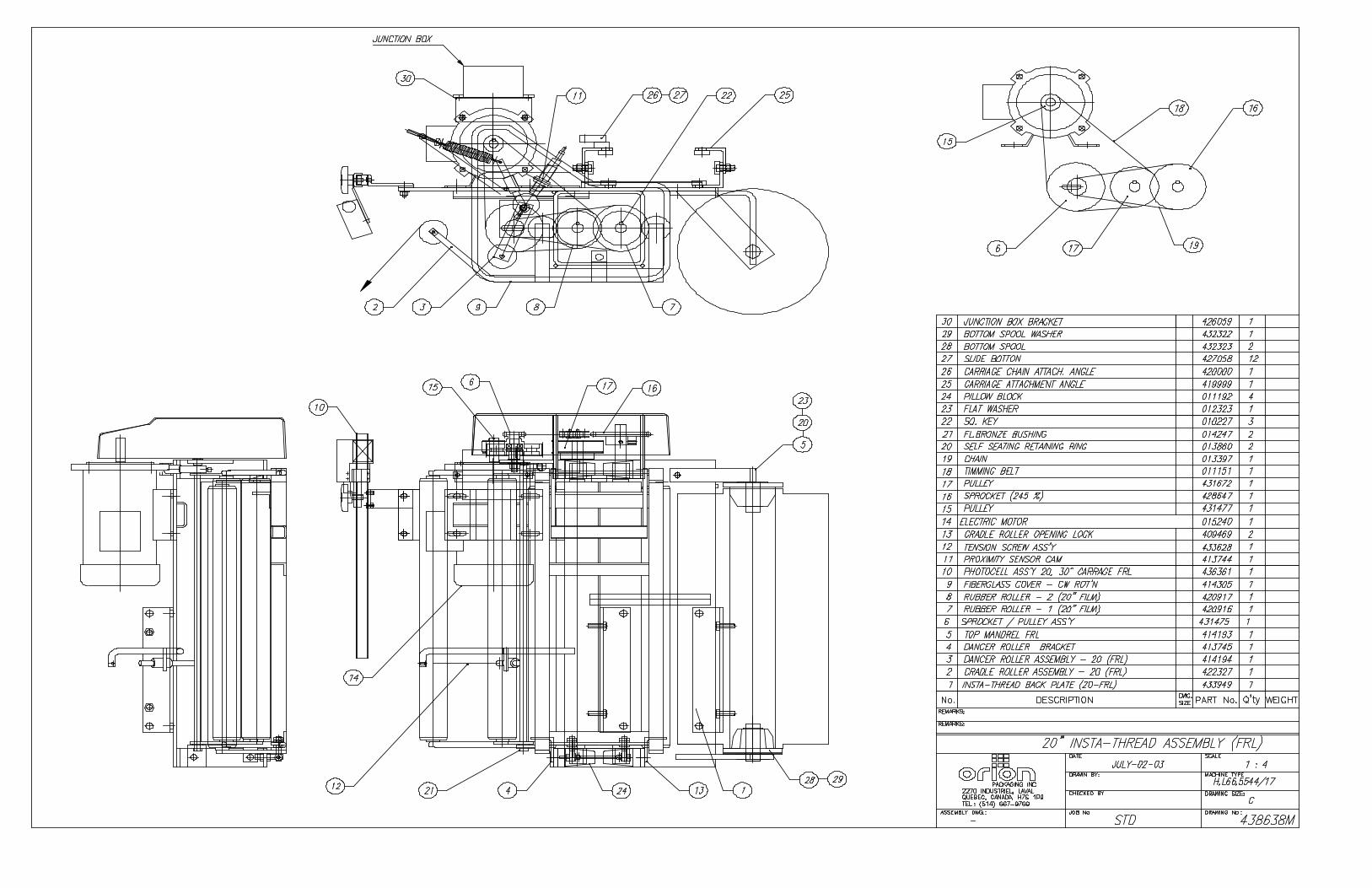
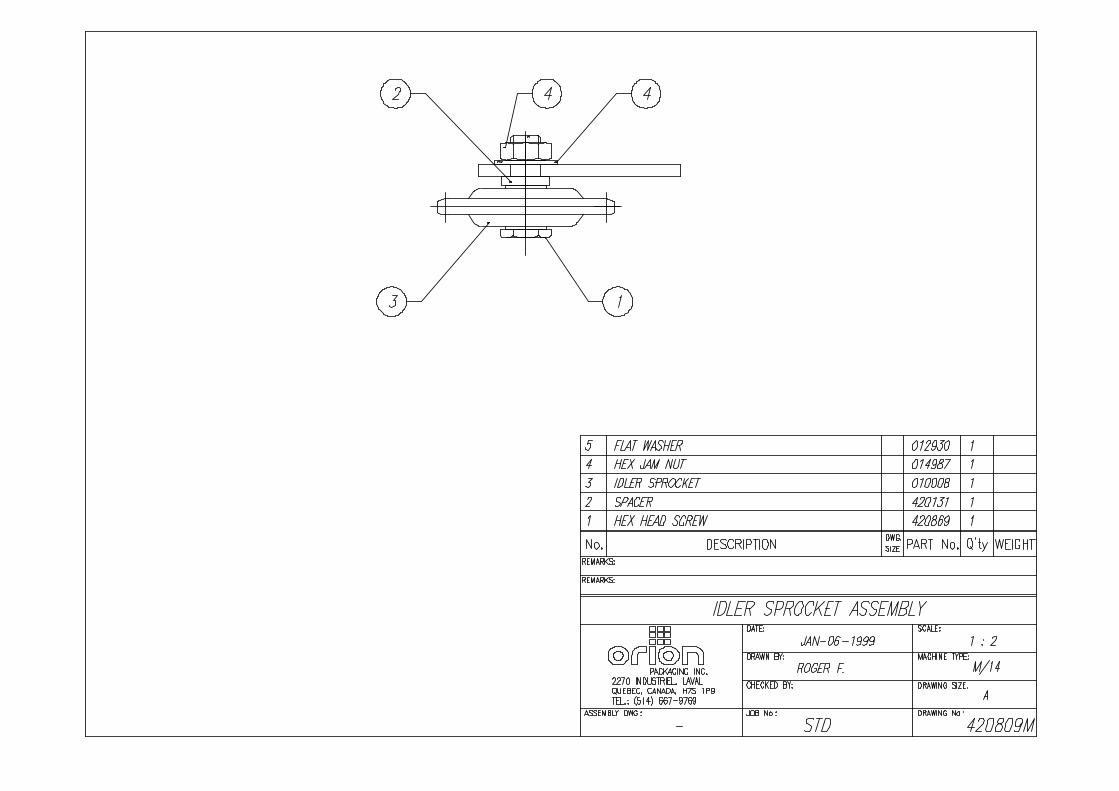
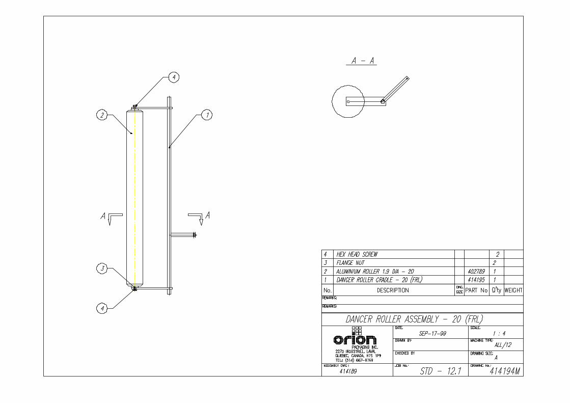
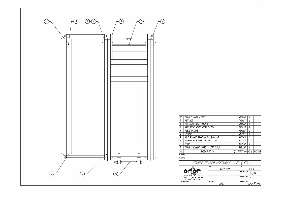
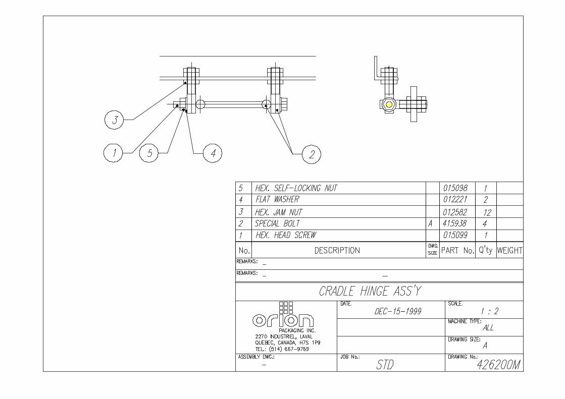
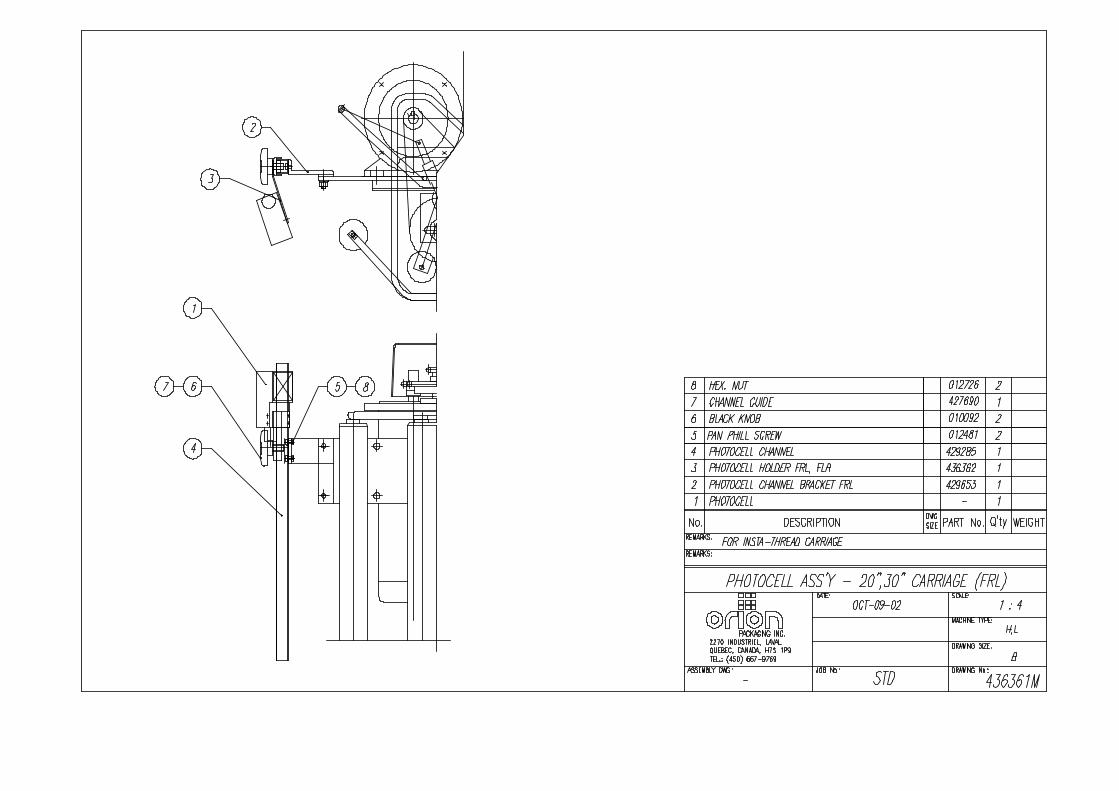
SEMI-AUTOMATIC STANDARD ASSEMBLY
PART LIST
Note : * Quantity listed in order of part number
** The names given to the parts are generic

APPENDIX
Multistretch Interface Board Calibration Instructions For MIB-336 Interface Board.
Adjustments: Gain; The Pot controls the system Gain. This control injects an offset voltage, which adds or subtracts from the voltage reference defined by the External Tension Adjustment (Film Tension Potentiometer); his will allow extremes of adjustment to be set to levels consistent with proper operation. Typically, the Gain will be used to center the operating range in linear portion of its characteristics.
Note: This adjustment is normally made at the factory and should not require fields adjustment. Zero: The Pot controls the system loop gain. This system loop gain may be adjusted if the motor continues to be energized when the dancer arm is unloaded and at rest. With the machine stopped, the potentiometer should be adjusted to ensure that the motor is de-energized in this condition, and so that a light pull on the free end of the film causes the film to feed freely. Counter clockwise (CCW) adjustment of this potentiometer will increase the response time i.e. (soften the motor tension response). Clockwise (CW) adjustment decreases the response time i.e. (sharpen the motor response) plus increases the maximum possible motor speed attainable. Trip: The output relay located on MIB-336 Board ( Outputs: Com (14); NO(13); NC(15) ) energized when the voltage between (11) & (12) overshoots the level selected on the potentiometer marked “Trip”. It de-energizes when the voltage falls below the normal current by approximately 5% or when power to board breaks.