model fc om - texpetrol · api 6a requirements (pr-psl) api 14d requirements (class of service)...
TRANSCRIPT
VALVEWORKS USA
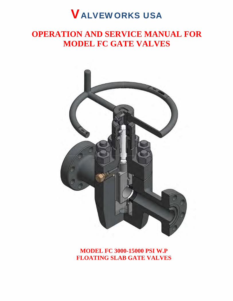
OPERATION AND SERVICE MANUAL FOR MODEL FC GATE VALVES
MODEL FC 3000-15000 PSI W.P
FLOATING SLAB GATE VALVES
VALVEWORKS USA Model FC Operation Manual
Proprietary Booklet of Valveworks USA. Do not reproduce without explicit permission.
Address: 1650 Swan Lake Road, Bossier City, LA-71111. Ph # 888-425-0266. Fax # 318-425-0934 2
INTRODUCTION In appreciation to our customer for purchasing our product, we have prepared this Operation Manual to assist you in the Operation, Maintenance, Assembly and Installation of the Valveworks USA API 6A Model FC Gate Valves. We encourage you to follow recommendations in this booklet to attain the best possible service from our product, which is designed and proven to offer the service one can expect of a quality product. If you need to contact a representative for more specific information pertaining to a special problem, you should contact:
VALVEWORKS USA 1650 SWAN LAKE RD.
BOSSIER CITY, LA 71111 PHONE: 318-425-0266
FAX# 318-425-0934 TOLL FREE: 888-425-0266
EMAIL: [email protected] WEBSITE: WWW.VALVEWORKSUSA.COM
CONTENTS APPLICATIONS ......................................................................................................................................................... 3
TEMPERATURE RATING ....................................................................................................................................... 3
TRIM CHART ............................................................................................................................................................. 3
ORDERING INFORMATION .................................................................................................................................. 4
OPERATION ............................................................................................................................................................... 4
ASSEMBLY INSTRUCTIONS .................................................................................................................................. 5
BODY SUB-ASSEMBLY .................................................................................................................................................. 5 BONNET SUB-ASSEMBLY ..............................................................................................................................................7 FINAL ASSEMBLY .......................................................................................................................................................... 8 BACK SEATING PROCEDURE ...................................................................................................................................... 10
ASSEMBLY DRAWING .......................................................................................................................................... 11
BILL OF MATERIALS .......................................................................................................................................... ..12
PHYSICAL DIMENSIONS ...................................................................................................................................... 14
PERIODIC MAINTENANCE .................................................................................................................................. 15
MAINTENANCE TOOLS ............................................................................................................................................... 15 STEM BEARING LUBRICATION ................................................................................................................................... 15 STEM PACKING ........................................................................................................................................................... 16 PROCEDURE TO VENT OR DRAIN ......................................................................................................................16MAINTAINANCE INTERVALS ..................................................................................................................................... 17
TROUBLESHOOTING ............................................................................................................................................ 17
REPLACING SHEAR PIN .............................................................................................................................................. 18
TEST PROCEDURE ................................................................................................................................................. 18
HYDROSTATIC BODY TEST ......................................................................................................................................... 20 HYDROSTATIC SEAT TEST .......................................................................................................................................... 21
VISUAL INSPECTION ............................................................................................................................................ 22
FIELD HOOK UP INSTRUCTIONS ...................................................................................................................... 23
VALVEWORKS USA Model FC Operation Manual
Proprietary Booklet of Valveworks USA. Do not reproduce without explicit permission.
Address: 1650 Swan Lake Road, Bossier City, LA-71111. Ph # 888-425-0266. Fax # 318-425-0934 3
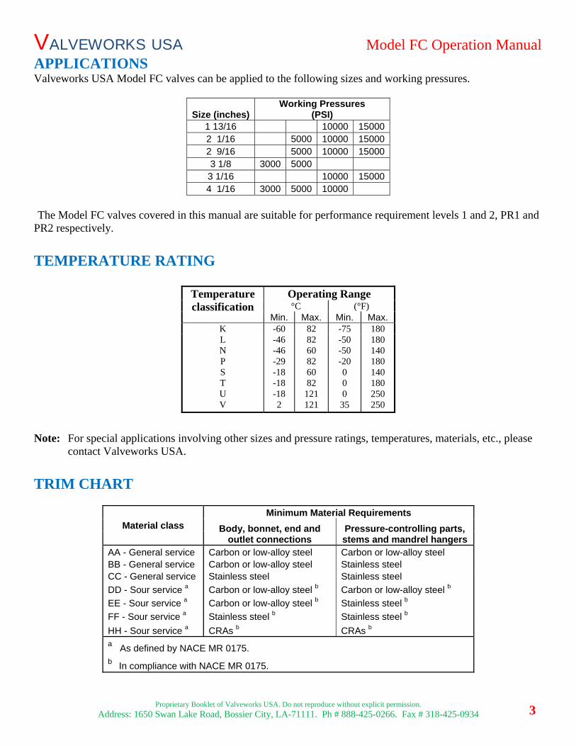
APPLICATIONSValveworks USA Model FC valves can be applied to the following sizes and working pressures.
Size (inches)Working Pressures
(PSI) 1 13/16 10000 150002 1/16 5000 10000 150002 9/16 5000 10000 150003 1/8 3000 50003 1/16 10000 150004 1/16 3000 5000 10000
The Model FC valves covered in this manual are suitable for performance requirement levels 1 and 2, PR1 and PR2 respectively.
TEMPERATURE RATING
Note: For special applications involving other sizes and pressure ratings, temperatures, materials, etc., please contact Valveworks USA.
TRIM CHART
Material class Minimum Material Requirements
Body, bonnet, end and outlet connections
Pressure-controlling parts, stems and mandrel hangers
AA - General service Carbon or low-alloy steel Carbon or low-alloy steel BB - General service Carbon or low-alloy steel Stainless steel CC - General service Stainless steel Stainless steel
DD - Sour service a Carbon or low-alloy steel b Carbon or low-alloy steel b
EE - Sour service a Carbon or low-alloy steel b Stainless steel b
FF - Sour service a Stainless steel b Stainless steel b
HH - Sour service a CRAs b CRAs b a As defined by NACE MR 0175. b In compliance with NACE MR 0175.
Temperature classification
Operating Range°C (°F)
Min. Max. Min. Max.K -60 82 -75 180L N P S T U V
-46 -46 -29 -18 -18 -18 2
82 60 82 60 82
121 121
-50 -50 -20 0 0 0
35
180 140 180 140 180 250 250
VALVEWORKS USA Model FC Operation Manual
Proprietary Booklet of Valveworks USA. Do not reproduce without explicit permission.
Address: 1650 Swan Lake Road, Bossier City, LA-71111. Ph # 888-425-0266. Fax # 318-425-0934 4
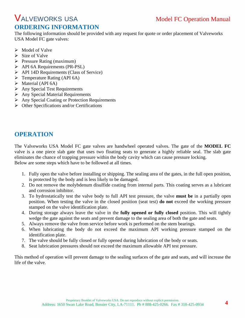
ORDERING INFORMATION The following information should be provided with any request for quote or order placement of Valveworks USA Model FC gate valves:
Model of Valve Size of Valve Pressure Rating (maximum) API 6A Requirements (PR-PSL) API 14D Requirements (Class of Service) Temperature Rating (API 6A) Material (API 6A) Any Special Test Requirements Any Special Material Requirements Any Special Coating or Protection Requirements Other Specifications and/or Certifications
OPERATION
The Valveworks USA Model FC gate valves are handwheel operated valves. The gate of the MODEL FC valve is a one piece slab gate that uses two floating seats to generate a highly reliable seal. The slab gate eliminates the chance of trapping pressure within the body cavity which can cause pressure locking. Below are some steps which have to be followed at all times.
1. Fully open the valve before installing or shipping. The sealing area of the gates, in the full open position,is protected by the body and is less likely to be damaged.
2. Do not remove the molybdenum disulfide coating from internal parts. This coating serves as a lubricantand corrosion inhibitor.
3. To hydrostatically test the valve body to full API test pressure, the valve must be in a partially openposition. When testing the valve in the closed position (seat test) do not exceed the working pressurestamped on the valve identification plate.
4. During storage always leave the valve in the fully opened or fully closed position. This will tightlywedge the gate against the seats and prevent damage to the sealing area of both the gate and seats.
5. Always remove the valve from service before work is performed on the stem bearings.6. When lubricating the body do not exceed the maximum API working pressure stamped on the
identification plate.7. The valve should be fully closed or fully opened during lubrication of the body or seats.8. Seat lubrication pressures should not exceed the maximum allowable API test pressure.
This method of operation will prevent damage to the sealing surfaces of the gate and seats, and will increase the life of the valve.
VALVEWORKS USA Model FC Operation Manual
Proprietary Booklet of Valveworks USA. Do not reproduce without explicit permission.
Address: 1650 Swan Lake Road, Bossier City, LA-71111. Ph # 888-425-0266. Fax # 318-425-0934 5
ASSEMBLY INSTRUCTIONS
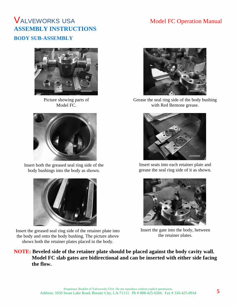
BODY SUB-ASSEMBLY
NOTE: Beveled side of the retainer plate should be placed against the body cavity wall. Model FC slab gates are bidirectional and can be inserted with either side facing the flow.
Picture showing parts of Model FC.
Grease the seal ring side of the body bushing with Red Bentone grease.
Insert both the greased seal ring side of the body bushings into the body as shown.
Insert seats into each retainer plate and grease the seal ring side of it as shown.
Insert the greased seal ring side of the retainer plate into the body and onto the body bushing. The picture above
shows both the retainer plates placed in the body.
Insert the gate into the body, between the retainer plates.
VALVEWORKS USA Model FC Operation Manual
Proprietary Booklet of Valveworks USA. Do not reproduce without explicit permission.
Address: 1650 Swan Lake Road, Bossier City, LA-71111. Ph # 888-425-0266. Fax # 318-425-0934 6
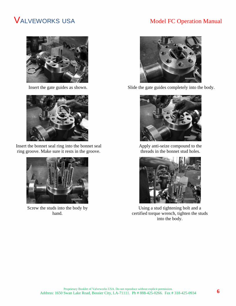
Insert the gate guides as shown.
Insert the bonnet seal ring into the bonnet seal ring groove. Make sure it rests in the groove.
Apply anti-seize compound to the threads in the bonnet stud holes.
Screw the studs into the body by hand.
Using a stud tightening bolt and a certified torque wrench, tighten the studs
into the body.
Slide the gate guides completely into the body.

VALVEWORKS USA Model FC Operation Manual
Proprietary Booklet of Valveworks USA. Do not reproduce without explicit permission.
Address: 1650 Swan Lake Road, Bossier City, LA-71111. Ph # 888-425-0266. Fax # 318-425-0934 7
BONNET SUB-ASSEMBLY
Place the packing over the stem.
Grease the bearing-race sets as shown. Apply anti-seize compound to the inside threads of bonnet and screw in the packing gland until the stem is visible.
Push the packing inside the bonnet as shown.
The bonnet assembly parts for Model FC are shown. Insert the stem through the bottom of the bonnet.
Place the bearing-race set over the top and bottom of the stem adapter.
Apply anti-seize to the bottom bearing of the stem adapter.
VALVEWORKS USA Model FC Operation Manual
Proprietary Booklet of Valveworks USA. Do not reproduce without explicit permission.
Address: 1650 Swan Lake Road, Bossier City, LA-71111. Ph # 888-425-0266. Fax # 318-425-0934 8
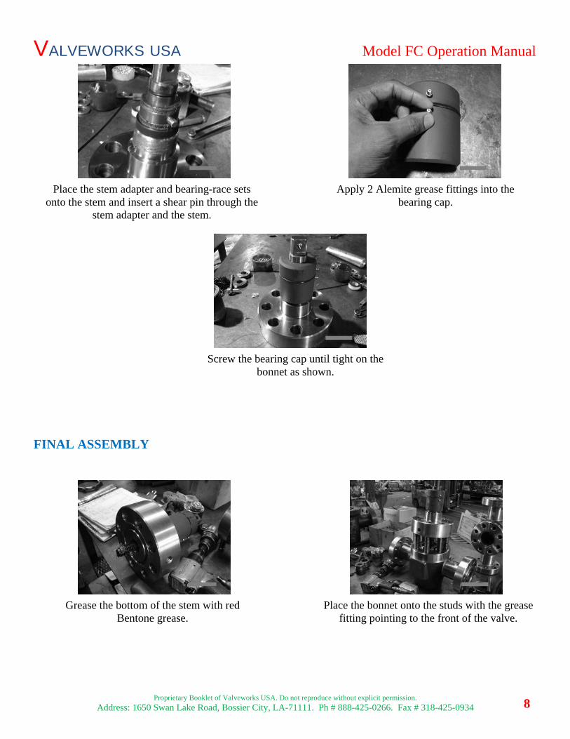
FINAL ASSEMBLY
Place the stem adapter and bearing-race sets onto the stem and insert a shear pin through the
stem adapter and the stem.
Apply 2 Alemite grease fittings into the bearing cap.
Screw the bearing cap until tight on the bonnet as shown.
Grease the bottom of the stem with red Bentone grease.
Place the bonnet onto the studs with the grease fitting pointing to the front of the valve.
VALVEWORKS USA Model FC Operation Manual
Proprietary Booklet of Valveworks USA. Do not reproduce without explicit permission.
Address: 1650 Swan Lake Road, Bossier City, LA-71111. Ph # 888-425-0266. Fax # 318-425-0934 9
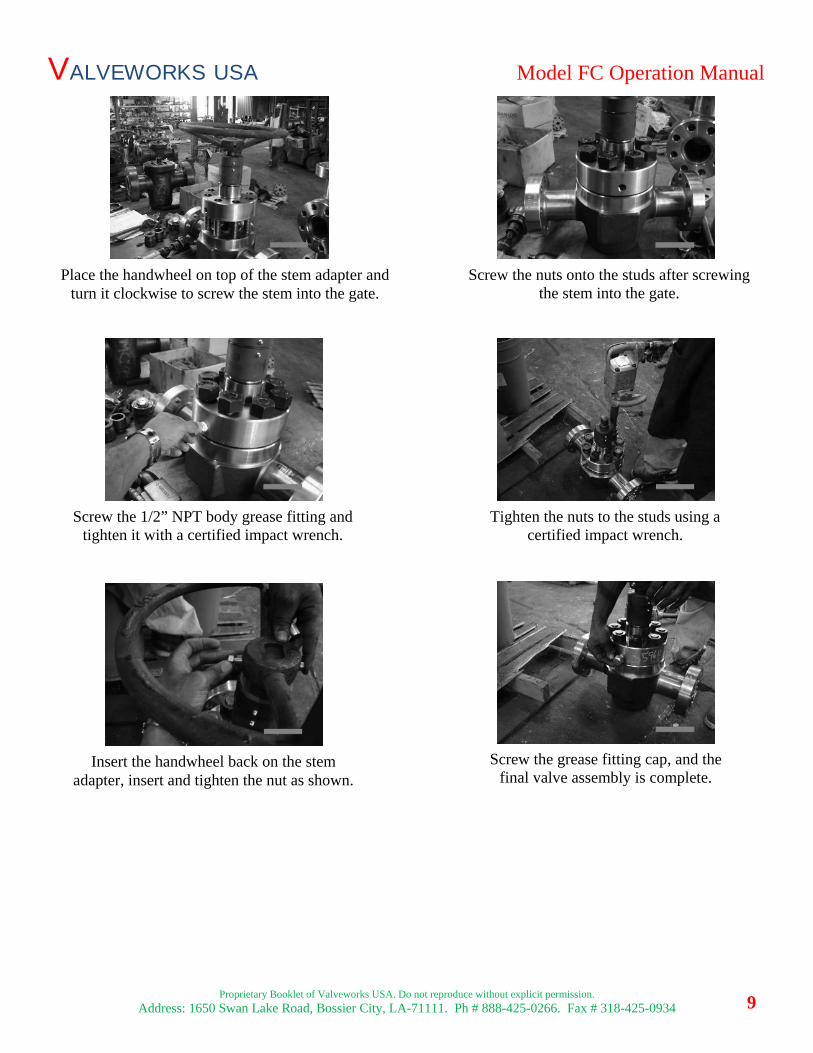
Place the handwheel on top of the stem adapter and turn it clockwise to screw the stem into the gate.
Screw the nuts onto the studs after screwing the stem into the gate.
Screw the 1/2” NPT body grease fitting and tighten it with a certified impact wrench.
Tighten the nuts to the studs using a certified impact wrench.
Insert the handwheel back on the stem adapter, insert and tighten the nut as shown.
Screw the grease fitting cap, and the final valve assembly is complete.
VALVEWORKS USA Model FC Operation Manual
Proprietary Booklet of Valveworks USA. Do not reproduce without explicit permission.
Address: 1650 Swan Lake Road, Bossier City, LA-71111. Ph # 888-425-0266. Fax # 318-425-0934 10
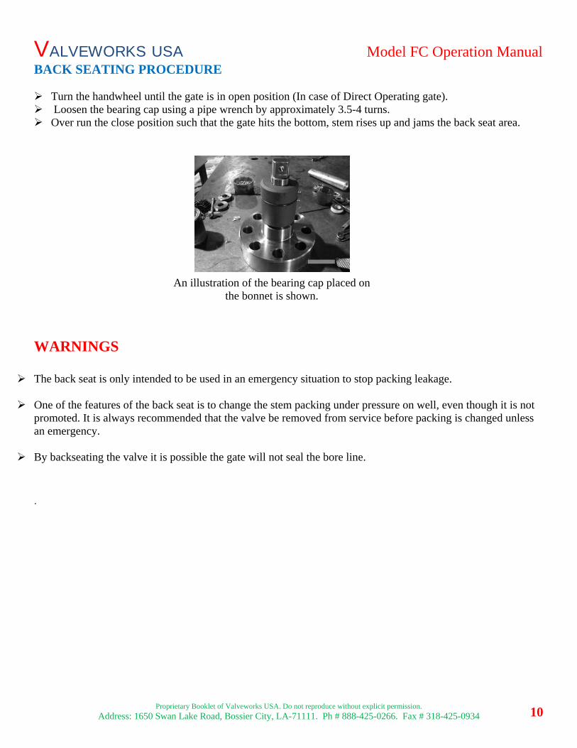
BACK SEATING PROCEDURE
Turn the handwheel until the gate is in open position (In case of Direct Operating gate). Loosen the bearing cap using a pipe wrench by approximately 3.5-4 turns. Over run the close position such that the gate hits the bottom, stem rises up and jams the back seat area.
WARNINGS
The back seat is only intended to be used in an emergency situation to stop packing leakage.
One of the features of the back seat is to change the stem packing under pressure on well, even though it is notpromoted. It is always recommended that the valve be removed from service before packing is changed unlessan emergency.
By backseating the valve it is possible the gate will not seal the bore line.
.
An illustration of the bearing cap placed on the bonnet is shown.
VALVEWORKS USA Model FC Operation Manual
Proprietary Booklet of Valveworks USA. Do not reproduce without explicit permission.
Address: 1650 Swan Lake Road, Bossier City, LA-71111. Ph # 888-425-0266. Fax # 318-425-0934 11
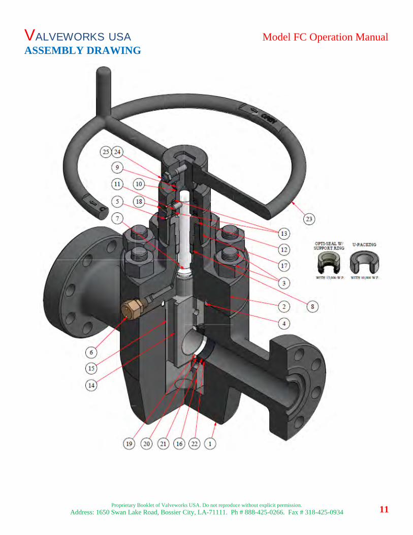
ASSEMBLY DRAWING
VALVEWORKS USA Model FC Operation Manual
Proprietary Booklet of Valveworks USA. Do not reproduce without explicit permission.
Address: 1650 Swan Lake Road, Bossier City, LA-71111. Ph # 888-425-0266. Fax # 318-425-0934 12
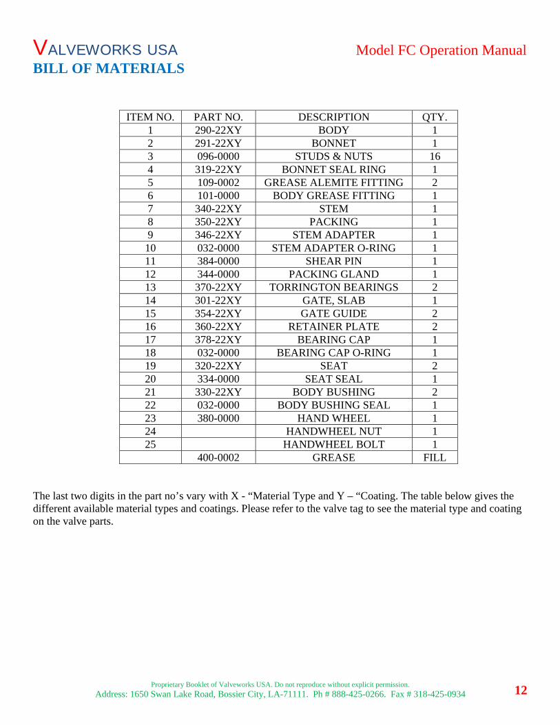
BILL OF MATERIALS
ITEM NO. PART NO. DESCRIPTION QTY. 1 290-22XY BODY 1 2 291-22XY BONNET 1 3 096-0000 STUDS & NUTS 164 319-22XY BONNET SEAL RING 1 5 109-0002 GREASE ALEMITE FITTING 2 6 101-0000 BODY GREASE FITTING 1 7 340-22XY STEM 1 8 350-22XY PACKING 1 9 346-22XY STEM ADAPTER 1 10 032-0000 STEM ADAPTER O-RING 1 11 384-0000 SHEAR PIN 1 12 344-0000 PACKING GLAND 1 13 370-22XY TORRINGTON BEARINGS 2 14 301-22XY GATE, SLAB 1 15 354-22XY GATE GUIDE 2 16 360-22XY RETAINER PLATE 2 17 378-22XY BEARING CAP 1 18 032-0000 BEARING CAP O-RING 1 19 320-22XY SEAT 2 20 334-0000 SEAT SEAL 1 21 330-22XY BODY BUSHING 2 22 032-0000 BODY BUSHING SEAL 1 23 380-0000 HAND WHEEL 1 24 HANDWHEEL NUT 125 HANDWHEEL BOLT 1
400-0002 GREASE FILL
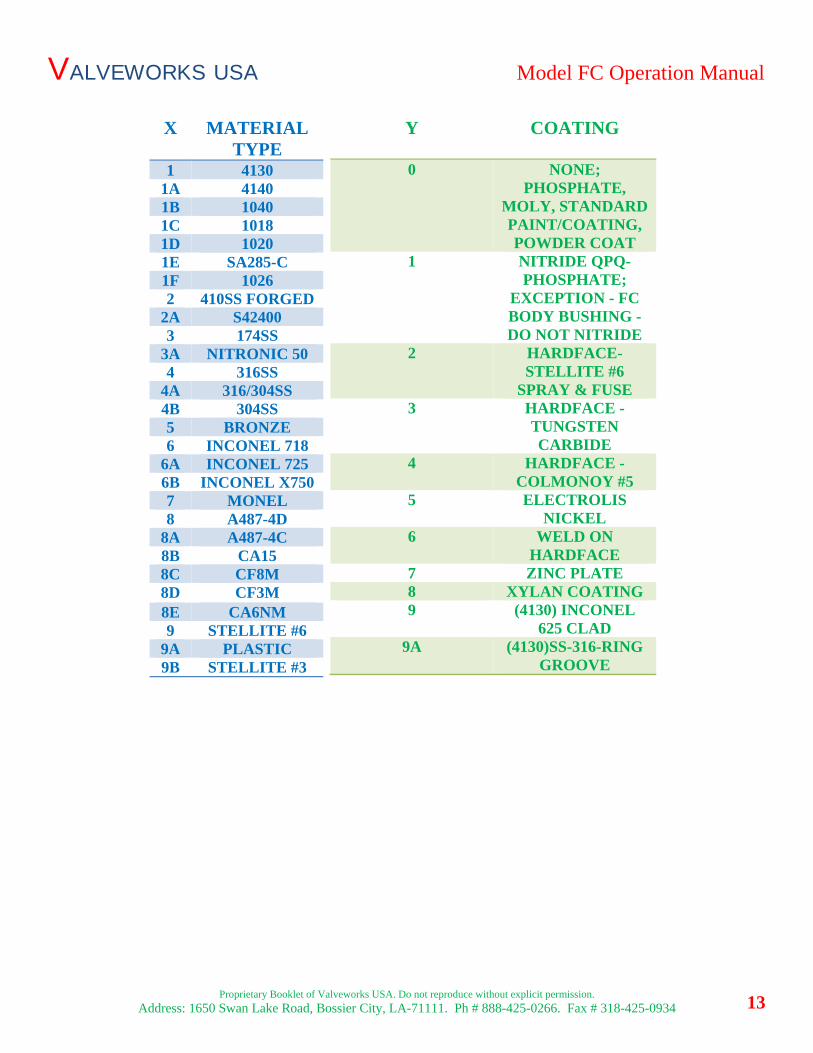
The last two digits in the part no’s vary with X - “Material Type and Y – “Coating. The table below gives the different available material types and coatings. Please refer to the valve tag to see the material type and coating on the valve parts.
VALVEWORKS USA Model FC Operation Manual
Proprietary Booklet of Valveworks USA. Do not reproduce without explicit permission.
Address: 1650 Swan Lake Road, Bossier City, LA-71111. Ph # 888-425-0266. Fax # 318-425-0934 13
X MATERIAL TYPE
Y COATING
0 NONE; PHOSPHATE,
MOLY, STANDARD PAINT/COATING, POWDER COAT
1 NITRIDE QPQ-PHOSPHATE;
EXCEPTION - FC BODY BUSHING - DO NOT NITRIDE
2 HARDFACE-STELLITE #6
SPRAY & FUSE 3 HARDFACE -
TUNGSTEN CARBIDE
4 HARDFACE - COLMONOY #5
5 ELECTROLISNICKEL
6 WELD ON HARDFACE
7 ZINC PLATE8 XYLAN COATING 9 (4130) INCONEL
625 CLAD 9A (4130)SS-316-RING
GROOVE
1 4130 1A 4140 1B 1040 1C 1018 1D 1020 1E SA285-C 1F 1026 2 410SS FORGED
2A S42400 3 174SS
3A NITRONIC 50 4 316SS
4A 316/304SS 4B 304SS 5 BRONZE 6 INCONEL 718
6A INCONEL 725 6B INCONEL X750 7 MONEL 8 A487-4D
8A A487-4C 8B CA15 8C CF8M 8D CF3M 8E CA6NM 9 STELLITE #6
9A PLASTIC 9B STELLITE #3
VALVEWORKS USA Model FC Operation Manual
Proprietary Booklet of Valveworks USA. Do not reproduce without explicit permission.
Address: 1650 Swan Lake Road, Bossier City, LA-71111. Ph # 888-425-0266. Fax # 318-425-0934 14
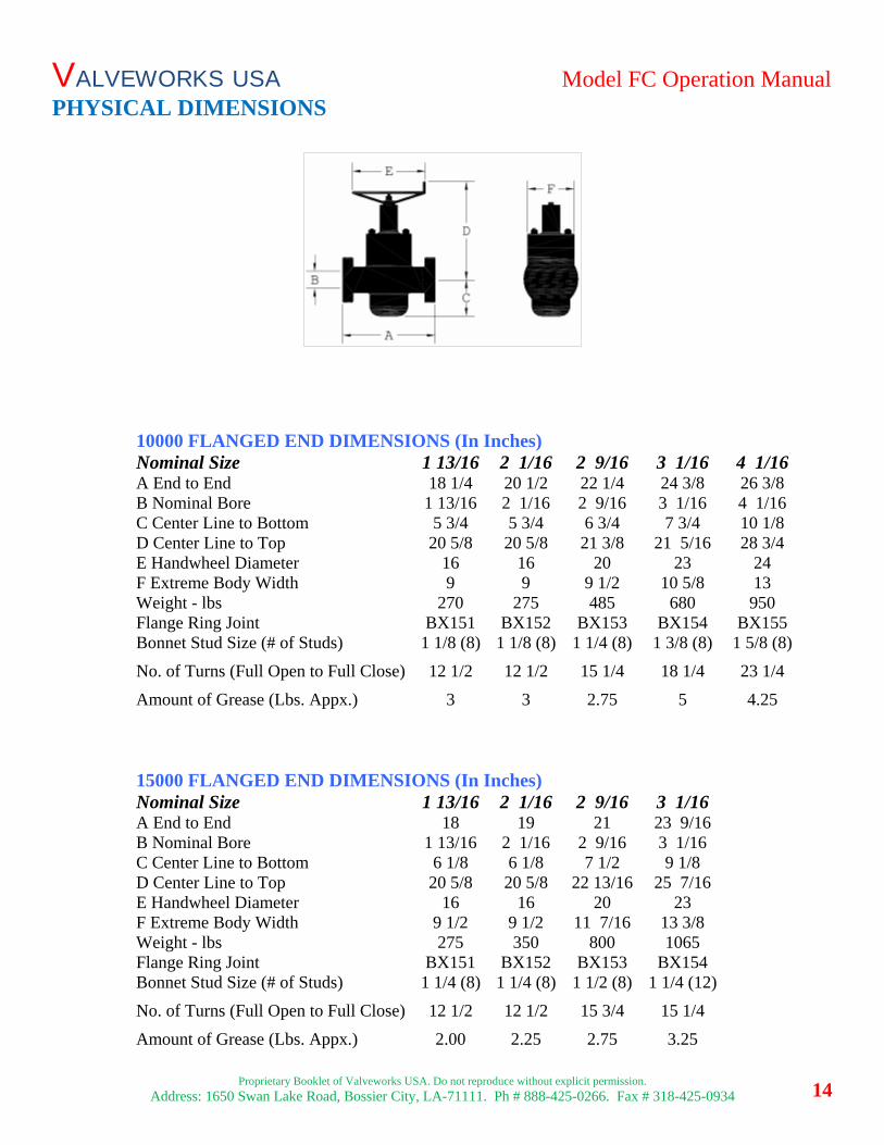
PHYSICAL DIMENSIONS
10000 FLANGED END DIMENSIONS (In Inches) Nominal Size 1 13/16 2 1/16 2 9/16 3 1/16 4 1/16 A End to End 18 1/4 20 1/2 22 1/4 24 3/8 26 3/8 B Nominal Bore 1 13/16 2 1/16 2 9/16 3 1/16 4 1/16 C Center Line to Bottom 5 3/4 5 3/4 6 3/4 7 3/4 10 1/8 D Center Line to Top 20 5/8 20 5/8 21 3/8 21 5/16 28 3/4 E Handwheel Diameter 16 16 20 23 24 F Extreme Body Width 9 9 9 1/2 10 5/8 13 Weight - lbs 270 275 485 680 950 Flange Ring Joint BX151 BX152 BX153 BX154 BX155 Bonnet Stud Size (# of Studs) 1 1/8 (8) 1 1/8 (8) 1 1/4 (8) 1 3/8 (8) 1 5/8 (8)
No. of Turns (Full Open to Full Close) 12 1/2 12 1/2 15 1/4 18 1/4 23 1/4
Amount of Grease (Lbs. Appx.) 3 3 2.75 5 4.25
15000 FLANGED END DIMENSIONS (In Inches) Nominal Size 1 13/16 2 1/16 2 9/16 3 1/16 A End to End 18 19 21 23 9/16 B Nominal Bore 1 13/16 2 1/16 2 9/16 3 1/16 C Center Line to Bottom 6 1/8 6 1/8 7 1/2 9 1/8 D Center Line to Top 20 5/8 20 5/8 22 13/16 25 7/16 E Handwheel Diameter 16 16 20 23 F Extreme Body Width 9 1/2 9 1/2 11 7/16 13 3/8 Weight - lbs 275 350 800 1065 Flange Ring Joint BX151 BX152 BX153 BX154 Bonnet Stud Size (# of Studs) 1 1/4 (8) 1 1/4 (8) 1 1/2 (8) 1 1/4 (12)
No. of Turns (Full Open to Full Close) 12 1/2 12 1/2 15 3/4 15 1/4
Amount of Grease (Lbs. Appx.) 2.00 2.25 2.75 3.25
VALVEWORKS USA Model FC Operation Manual
Proprietary Booklet of Valveworks USA. Do not reproduce without explicit permission.
Address: 1650 Swan Lake Road, Bossier City, LA-71111. Ph # 888-425-0266. Fax # 318-425-0934
15
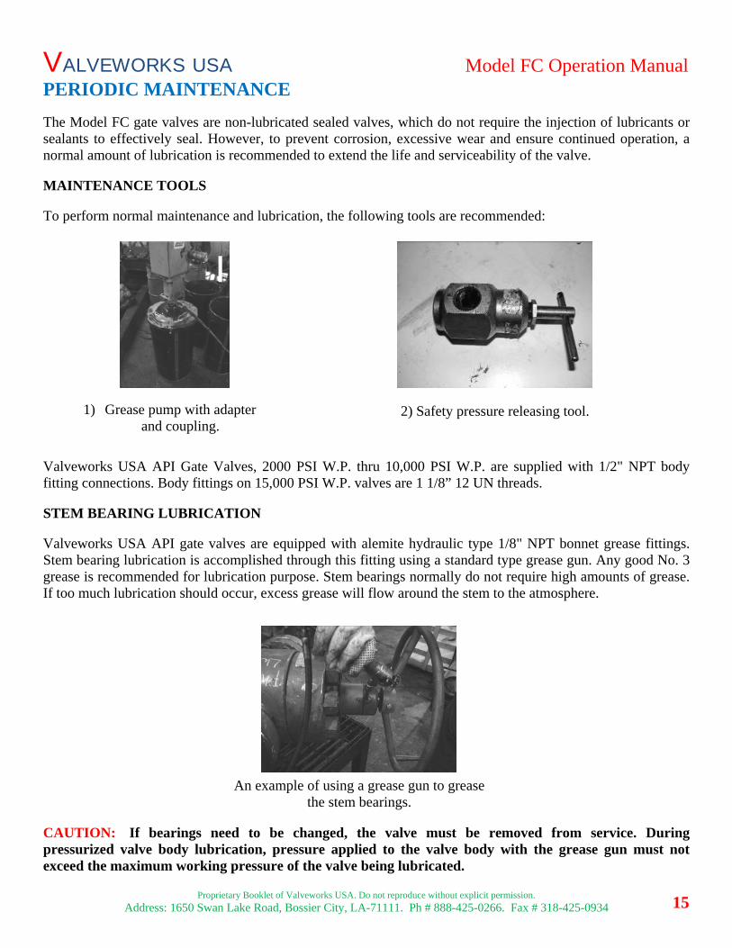
PERIODIC MAINTENANCE
The Model FC gate valves are non-lubricated sealed valves, which do not require the injection of lubricants or sealants to effectively seal. However, to prevent corrosion, excessive wear and ensure continued operation, a normal amount of lubrication is recommended to extend the life and serviceability of the valve. MAINTENANCE TOOLS To perform normal maintenance and lubrication, the following tools are recommended: Valveworks USA API Gate Valves, 2000 PSI W.P. thru 10,000 PSI W.P. are supplied with 1/2" NPT body fitting connections. Body fittings on 15,000 PSI W.P. valves are 1 1/8” 12 UN threads. STEM BEARING LUBRICATION Valveworks USA API gate valves are equipped with alemite hydraulic type 1/8" NPT bonnet grease fittings. Stem bearing lubrication is accomplished through this fitting using a standard type grease gun. Any good No. 3 grease is recommended for lubrication purpose. Stem bearings normally do not require high amounts of grease. If too much lubrication should occur, excess grease will flow around the stem to the atmosphere. CAUTION: If bearings need to be changed, the valve must be removed from service. During pressurized valve body lubrication, pressure applied to the valve body with the grease gun must not exceed the maximum working pressure of the valve being lubricated.
2) Safety pressure releasing tool. 1) Grease pump with adapter and coupling.
An example of using a grease gun to grease the stem bearings.
VALVEWORKS USA Model FC Operation Manual
Proprietary Booklet of Valveworks USA. Do not reproduce without explicit permission.
Address: 1650 Swan Lake Road, Bossier City, LA-71111. Ph # 888-425-0266. Fax # 318-425-0934
16
STEM PACKING Most products contain a certain amount of water, lime scale, sediment and other foreign matter which tend to accumulate in the valve body. A regular draining program will increase the life of a valve against damage caused by: 1) Water freezing in the body cavity, causing damage to the body. 2) An accumulation of foreign matter in the lower part of the body, which could prevent the valve from fully closing, resulting in a throttling action which may cause inefficient sealing. 3) Foreign matter trapped in the body may become lodged between the sealing surfaces of the gate and seats, resulting in scored or damaged sealed. 4) Venting a Model FC valve is a positive method of checking the sealing ability of the gate and seats. If the body vents down to zero pressure with the valve in fully closed position, this is definite indication that sealing surfaces are in good condition. PROCEDURE TO VENT OR DRAIN 1. Place the valve gate in a fully opened or fully closed position. 2. Remove the safety cap from either body grease fitting and attach the pressure release tool. CAUTION: Remove the safety cap slowly to allow the ball check to sufficiently seal, to avoid uncontrolled venting. Should the ball check fail to seal properly, pressure will continue to blow through the safety cap orifices. You should then retighten the safety cap screw and vent through the other body grease fitting. Once the body pressure is bled to zero you should then attempt to repair the leaking ball check. 3. Screw the stem of the releasing tool into the fitting forcing the ball check off its seat. The valve will vent and drain once the ball check is unseated. A program of regular draining and body venting is the most positive way to prevent problems caused by foreign matter in the valve. However, if a regular draining program cannot be followed, it is recommended that valves be drained after the following operations: 1) After a well has come in and has been cleaned up. 2) After a mudding operation. 3) After a cementing operation. 4) Anytime the valve seems hard to operate by hand and will not fully open or close by the required number of handwheel turns. 5) When the valve is hard to operate from the fully open or fully closed position because it is "pressure locked" or "Iced-up". "Pressure locked" is a condition that may exist with any dual seat expanding type gate valve when body pressure greatly exceeds line pressure. It occurs only in fully closed position and is a positive indication that sealing surfaces are in good condition. "Iced-up" is a condition caused by a restriction in the flow or a differential in the pressure of gas flow at high pressure, which produces extremely low temperatures. These restrictions or differentials in pressure may be caused by throttling through a valve, by leakage of a closed valve or by Leakage through the stem packing. Valves in service on gas containing hydrates or in fresh water service, exposed to low external temperatures
VALVEWORKS USA Model FC Operation Manual
Proprietary Booklet of Valveworks USA. Do not reproduce without explicit permission.
Address: 1650 Swan Lake Road, Bossier City, LA-71111. Ph # 888-425-0266. Fax # 318-425-0934
17
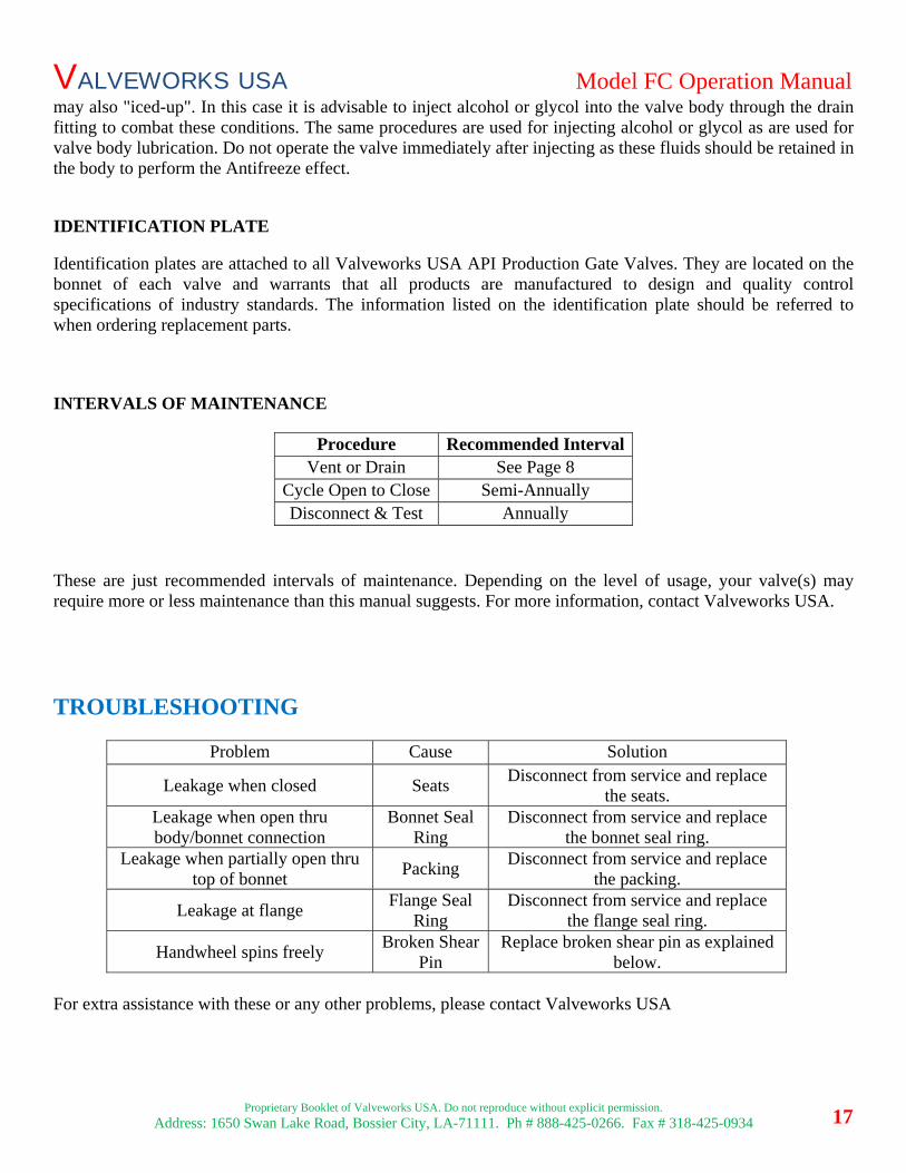
may also "iced-up". In this case it is advisable to inject alcohol or glycol into the valve body through the drain fitting to combat these conditions. The same procedures are used for injecting alcohol or glycol as are used for valve body lubrication. Do not operate the valve immediately after injecting as these fluids should be retained in the body to perform the Antifreeze effect. IDENTIFICATION PLATE Identification plates are attached to all Valveworks USA API Production Gate Valves. They are located on the bonnet of each valve and warrants that all products are manufactured to design and quality control specifications of industry standards. The information listed on the identification plate should be referred to when ordering replacement parts. INTERVALS OF MAINTENANCE
These are just recommended intervals of maintenance. Depending on the level of usage, your valve(s) may require more or less maintenance than this manual suggests. For more information, contact Valveworks USA.
TROUBLESHOOTING
Problem Cause Solution
Leakage when closed Seats Disconnect from service and replace
the seats. Leakage when open thru body/bonnet connection
Bonnet Seal Ring
Disconnect from service and replace the bonnet seal ring.
Leakage when partially open thru top of bonnet
Packing Disconnect from service and replace
the packing.
Leakage at flange Flange Seal
Ring Disconnect from service and replace
the flange seal ring.
Handwheel spins freely Broken Shear
Pin Replace broken shear pin as explained
below. For extra assistance with these or any other problems, please contact Valveworks USA
Procedure Recommended IntervalVent or Drain See Page 8
Cycle Open to Close Semi-Annually Disconnect & Test Annually
VALVEWORKS USA Model FC Operation Manual
Proprietary Booklet of Valveworks USA. Do not reproduce without explicit permission.
Address: 1650 Swan Lake Road, Bossier City, LA-71111. Ph # 888-425-0266. Fax # 318-425-0934
18
REPLACING BROKEN SHEAR PIN (WHILE IN SERVICE)
1) Remove hand wheel 2) Attempt to remove Bearing Cap.
a) If Bearing Cap tries to remove the packing gland hit the stem adapter firmly to break any gunk build up. b) If the Bearing Cap will not remove without the packing gland from unthreading. Pressure must be
removed from the valve or the valve MUST be back seated. c) Once Bearing Cap is free or Valve is back seated go to step 3.
3) Once Bearing Cap is removed replace damaged shear pin. 4) Retighten packing gland with pipe wrench (~100 ft*lbf)
a) Debur with sandpaper if needed. 5) Reassemble Bearing Cap (See Bonnet Sub-Assembly Section for details) 6) Tighten Bearing Cap with pipe wrench (~100 ft*lbf)
a) Debur with sandpaper if needed.
NOTE: NEVER REMOVE PACKING GLAND WHILE VALVE IS UNDER PRESSURE UNLESS THE PRESSURE HAS BEEN ISOLATED.
TEST PROCEDURE
NOTE: YOU CAN FIND THE FLANGE RING JOINT SIZE IN THE PHYSICAL DIMENSIONS SECTION OF THIS MANUAL.
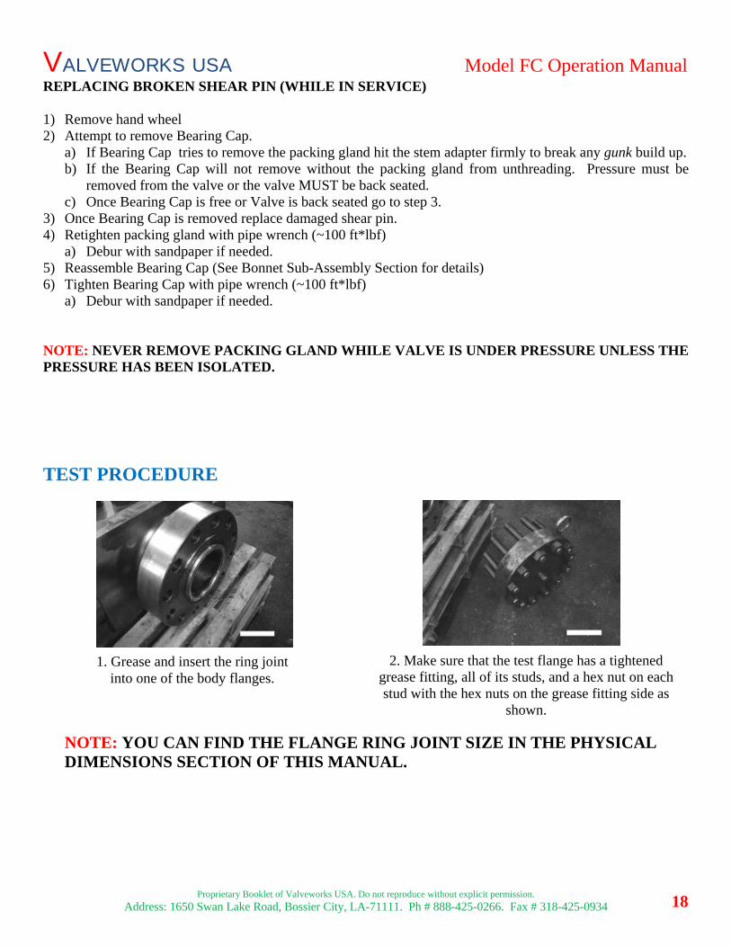
1. Grease and insert the ring joint into one of the body flanges.
2. Make sure that the test flange has a tightened grease fitting, all of its studs, and a hex nut on each stud with the hex nuts on the grease fitting side as
shown.
VALVEWORKS USA Model FC Operation Manual
Proprietary Booklet of Valveworks USA. Do not reproduce without explicit permission.
Address: 1650 Swan Lake Road, Bossier City, LA-71111. Ph # 888-425-0266. Fax # 318-425-0934
19
REPEAT STEPS 1-5 FOR THE OPPOSITE FLANGE. .
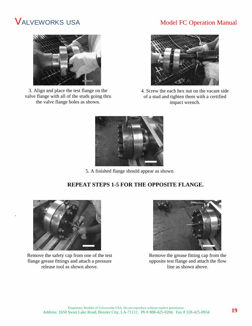
5. A finished flange should appear as shown.
Remove the safety cap from one of the test flange grease fittings and attach a pressure
release tool as shown above.
Remove the grease fitting cap from the opposite test flange and attach the flow
line as shown above.
3. Align and place the test flange on the valve flange with all of the studs going thru
the valve flange holes as shown.
4. Screw the each hex nut on the vacant side of a stud and tighten them with a certified
impact wrench.
VALVEWORKS USA Model FC Operation Manual
Proprietary Booklet of Valveworks USA. Do not reproduce without explicit permission.
Address: 1650 Swan Lake Road, Bossier City, LA-71111. Ph # 888-425-0266. Fax # 318-425-0934
20
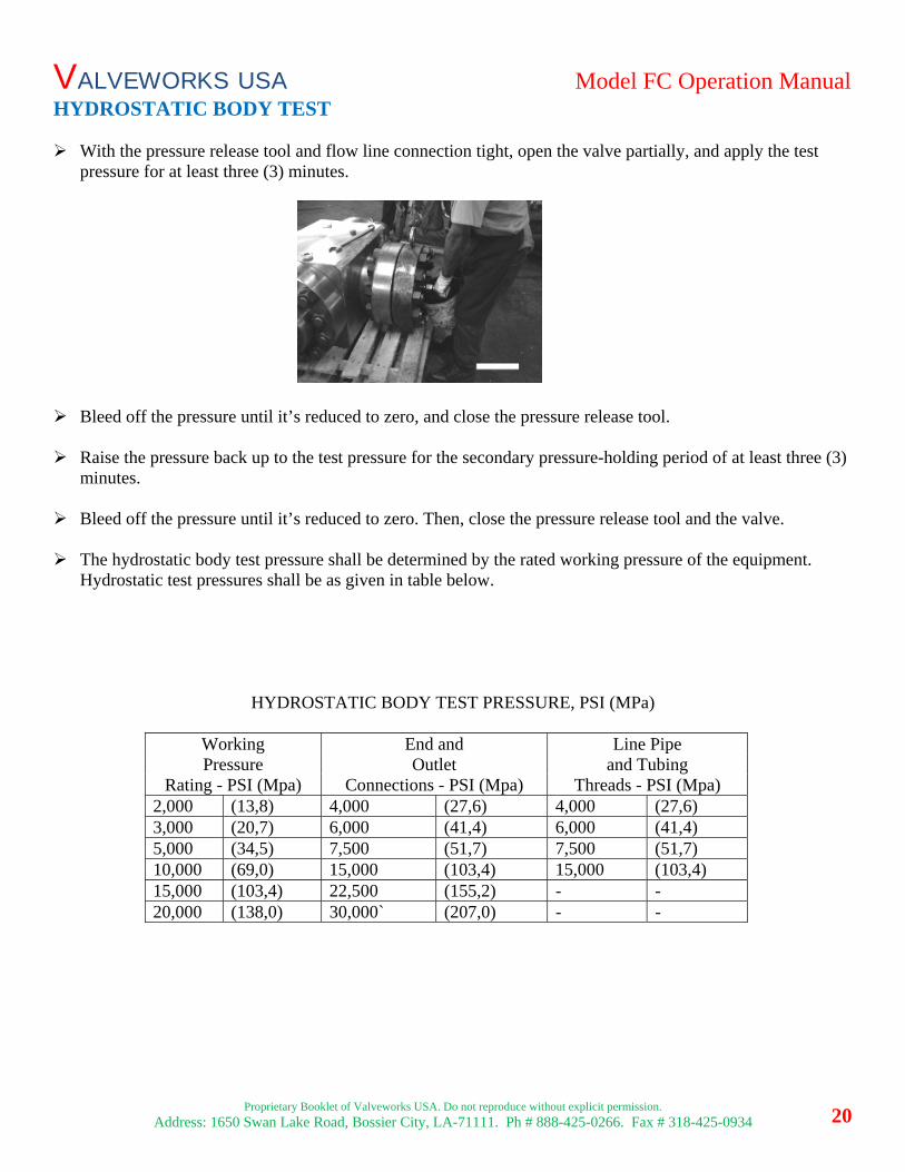
HYDROSTATIC BODY TEST With the pressure release tool and flow line connection tight, open the valve partially, and apply the test
pressure for at least three (3) minutes. Bleed off the pressure until it’s reduced to zero, and close the pressure release tool. Raise the pressure back up to the test pressure for the secondary pressure-holding period of at least three (3)
minutes. Bleed off the pressure until it’s reduced to zero. Then, close the pressure release tool and the valve. The hydrostatic body test pressure shall be determined by the rated working pressure of the equipment.
Hydrostatic test pressures shall be as given in table below.
HYDROSTATIC BODY TEST PRESSURE, PSI (MPa)
Working End and Line Pipe Pressure Outlet and Tubing
Rating - PSI (Mpa) Connections - PSI (Mpa) Threads - PSI (Mpa) 2,000 (13,8) 4,000 (27,6) 4,000 (27,6) 3,000 (20,7) 6,000 (41,4) 6,000 (41,4) 5,000 (34,5) 7,500 (51,7) 7,500 (51,7) 10,000 (69,0) 15,000 (103,4) 15,000 (103,4) 15,000 (103,4) 22,500 (155,2) - - 20,000 (138,0) 30,000` (207,0) - -
VALVEWORKS USA Model FC Operation Manual
Proprietary Booklet of Valveworks USA. Do not reproduce without explicit permission.
Address: 1650 Swan Lake Road, Bossier City, LA-71111. Ph # 888-425-0266. Fax # 318-425-0934
21
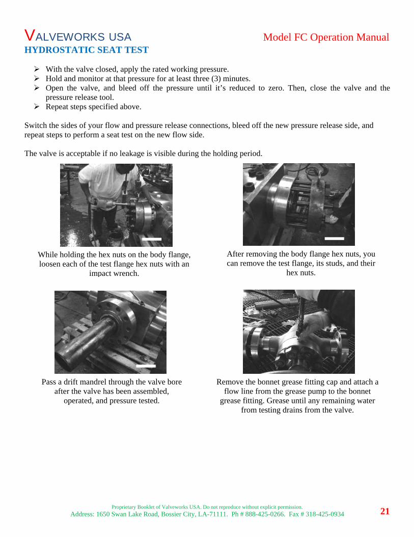
HYDROSTATIC SEAT TEST With the valve closed, apply the rated working pressure. Hold and monitor at that pressure for at least three (3) minutes. Open the valve, and bleed off the pressure until it’s reduced to zero. Then, close the valve and the
pressure release tool. Repeat steps specified above.
Switch the sides of your flow and pressure release connections, bleed off the new pressure release side, and repeat steps to perform a seat test on the new flow side. The valve is acceptable if no leakage is visible during the holding period.
While holding the hex nuts on the body flange, loosen each of the test flange hex nuts with an
impact wrench.
After removing the body flange hex nuts, you can remove the test flange, its studs, and their
hex nuts.
Pass a drift mandrel through the valve bore after the valve has been assembled,
operated, and pressure tested.
Remove the bonnet grease fitting cap and attach a flow line from the grease pump to the bonnet
grease fitting. Grease until any remaining water from testing drains from the valve.
VALVEWORKS USA Model FC Operation Manual
Proprietary Booklet of Valveworks USA. Do not reproduce without explicit permission.
Address: 1650 Swan Lake Road, Bossier City, LA-71111. Ph # 888-425-0266. Fax # 318-425-0934
22
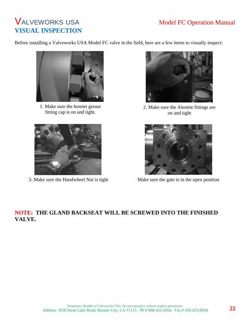
VISUAL INSPECTION Before installing a Valveworks USA Model FC valve in the field, here are a few items to visually inspect: NOTE: THE GLAND BACKSEAT WILL BE SCREWED INTO THE FINISHED VALVE.
1. Make sure the bonnet grease fitting cap is on and tight.
2. Make sure the Alemite fittings are on and tight
3. Make sure the Handwheel Nut is tight Make sure the gate is in the open position
VALVEWORKS USA Model FC Operation Manual
Proprietary Booklet of Valveworks USA. Do not reproduce without explicit permission.
Address: 1650 Swan Lake Road, Bossier City, LA-71111. Ph # 888-425-0266. Fax # 318-425-0934
23
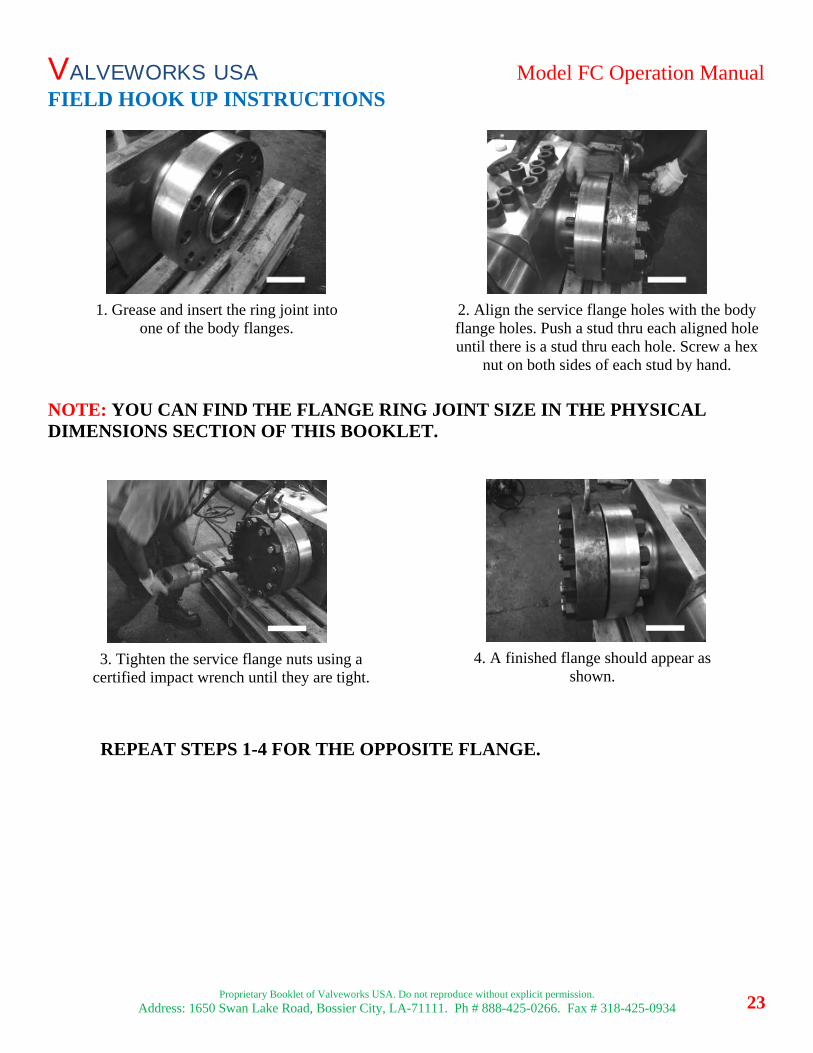
FIELD HOOK UP INSTRUCTIONS
NOTE: YOU CAN FIND THE FLANGE RING JOINT SIZE IN THE PHYSICAL DIMENSIONS SECTION OF THIS BOOKLET.
REPEAT STEPS 1-4 FOR THE OPPOSITE FLANGE.
2. Align the service flange holes with the body flange holes. Push a stud thru each aligned hole until there is a stud thru each hole. Screw a hex
nut on both sides of each stud by hand.
1. Grease and insert the ring joint into one of the body flanges.
4. A finished flange should appear as shown.
3. Tighten the service flange nuts using a certified impact wrench until they are tight.