model 910t cat. #50122-10 lapping and polishing machine · pdf filesupply for cooling and...
TRANSCRIPT

MODEL 910T CAT. #50122-10
LAPPING AND POLISHING MACHINE Instruction Manual
Lapping and Polishing

E L E C T R O N M I C R O S C O P Y S C I E N C E S
Model 910T Instruction Manual
EMS has a policy of continuing product development. The Company reserves the right to alter without notice, the specification, design or conditions of supply of any product or service. The Company expressly disclaims any
warranty that the goods are merchantable or fit for a particular purpose.
ELECTRON MICROSCOPY SCIENCES 321 Morris Road
Fort Washington, PA 19034 Toll Free in USA: 1.800.523.5874
Phone: 215.646.1566 Fax: 215.646.8931
Internet: www.emsdissum.com

Table of Contents1.0: Introduction 2 1.1: Specifications 2 2.0: Assembly and Construction 3-15 2.1: Shipping Kit 3 2.2: Optional Parts and Accessories 3 2.2.1: Lapping and Polishing Fixtures 4 2.2.2: Sample Mounting Fixtures 5 2.3: Instrument Layout 6 2.4: Instrument Setup 7-8 2.4.1: Water Supply 7 2.4.2: Drain Hose 7 2.4.3: Lapping Plate Mounting 7-8 2.4.4: Slurry Drip Bottle Installation 8 2.5: Accessories 9-15 2.5.1: 02-02261 Manual Specimen Yoke 9 2.5.2: 01-02262-01 Workstation Post 9-10 2.5.3: Model 92005 Tri-Holder Specimen Mount 10-12 2.5.4: Model 92006 Quad-Holder Specimen Mount 12-13 2.5.5: Model 92030 RPM Meter 13-14 3.0: Instrument Operation 15-22 3.1: Lapping and Polishing Basics 15 3.2: Lapping Plate Selection 15-18 3.2.1: Cast Fe Lapping Plates 15-17 3.2.2: Aluminum Lapping Plate 17-18 3.2.3: PVC Lapping Plate 18 3.3: Specimen Processing 19-20 3.3.1: Metallographic Specimens 19 3.3.2: Optical Crystals or Wafers 20 3.3.3: Electron Microscopy Cross Sections 20 3.4: Standard Operating Procedure 21 4.0: Maintenance and Service 22-23 4.1: General Maintenance 22 4.2: Belt Replacement 22-23 4.3: Motor Assembly 23 5.0: Safety 24

M O D E L 9 1 0 T I N S T R U C T I O N M A N U A L
CAT 50122-10 LAPPING AND POLISHING MACHINE.DOC 2
1.0: Introduction
The Model 910T is a multi purpose grinding and lapping machine designed for accurately lapping and polishing a wide range of materials. The Model 910T can be used as a standard metallurgical grinder and polisher using abrasive papers, films, polishing cloths, or diamond discs. It can also be used as a high precision, free abrasive lapping machine for flat polishing of optical and semiconductor materials. When used as a free abrasive lapping machine, the Model 910T can accommodate most EMS Lapping and Polishing fixtures to provide accurate specimen orientation and maximum flatness.
The Model 910T utilizes a high torque motor to provide maximum removal and is continuously variable in speed selection. Different motor speeds can be chosen, with variable speeds of 40-650 rpm or 3-60 rpm. With a solid, cast aluminum construction the Model 910T provides high stability, free of vibration, and quiet operation. The machine is provided with a water nozzle hookup to provide a constant water supply for cooling and removing material from the lapping surface. Optional workstations can also be added which allow for the automatic rotation of lapping fixtures, minimizing operator supervision.
Whether used with a glass plate for abrasive films, an aluminum plate for paper discs and diamond discs, or with a cast iron lapping plate for free abrasive polishing, the Model 910T provides high precision capabilities for all.
1.1: Specifications
Dimensions: 21” x 13” x 11” Net Weight: 60 lbs Motor Speed: 8-600 RPM Motor: 1/8 HP Wheel Diameter: 8” (200 mm) Electrical Input: 90-120 VAC; 50/60 Hz 200-240 VAC; 50/60 Hz < 4 amps

M O D E L 9 1 0 T I N S T R U C T I O N M A N U A L
CAT 50122-10 LAPPING AND POLISHING MACHINE.DOC 3
2.0: Assembly and Construction
2.1: Shipping Kit
The following parts and accessories are included in the Model 910T upon shipment. Check to ensure all of the parts are included with the instrument.
PART NUMBER DESCRIPTION QTY. CHECK
01-02224-01 SLURRY RESERVOIR MOUNTING BRACKET (CAT#50122-32) 1 0704-055 1 LITER CARBOY BOTTLE W/TUBE (CAT#50122-33) 1 0736-026 CLEAR TYGON TUBING, 0.125” DIAMETER (FOR WATER
SUPPLY) 1
LP 920A ALUMINUM LAPPING PLATE, 8” (CAT#50122-16) 1 01-02254 METAL HOLDING BAND (CAT#50122-31) 1 0537-047 O-RING FOR ALUMINUM LAPPING PLATE (CAT#50122-30) 1 0590-005 HOSE CLAMP (CAT#50122-34) 1 0705-012 8” DIAMETER GLASS PLATE (CAT#50124-15) 1 0541-028 HEX WRENCH HANDLE 1 0541-020 HEX WRENCH, 0.125” 1 0541-019 HEX WRENCH, 0.109” 1 0541-018 HEX WRENCH, 0.094” 1 0541-017 HEX WRENCH, 0.078” 1 0541-016 HEX WRENCH, 0.063” 1
TABLE 1: SHIPPING KIT CHECKLIST
2.2: Optional Parts and Accessories
The following parts and accessories can be purchased for the Model 910T . PART NUMBER DESCRIPTION 01-02262-01 WORKSTATION POST (FOR USE WITH MANUAL SPECIMEN YOKE) (CAT#50122-14) 02-02260-01 MANUAL SPECIMEN YOKE (CAT#50122-21) 01-02257-01 HOLDING BAND (CAT#50122-23) MODEL 92030 RPM METER
LP 920A ALUMINUM MASTER LAPPING PLATE (8”) (CAT#50122-16) LP 920M CAST IRON LAPPING PLATE (8” DIAMETER, FLAT PLATE) (CAT#50122-17)
LP 920MC CAST IRON LAPPING PLATE (8” DIAMETER, CONCENTRIC GROOVES) (CAT#50122-18) LP 920MS CAST IRON LAPPING PLATE (8” DIAMETER, SPIRAL GROOVES)(CAT#50122-19) LP 920MR CAST IRON LAPPING PLATE (8” DIAMETER, RADIAL GROOVES) LP 920P PVC MASTER LAPPING PLATE (8”) (CAT#50122-20)
01-02221-01 CONDITIONING RING (FOR USE ON LP 920M, MC, MS, MR)(CAT#50122-22) 01-02194-01 FLAT BELT DRIVE (FOR DRIVE MOTOR)

M O D E L 9 1 0 T I N S T R U C T I O N M A N U A L
CAT 50122-10 LAPPING AND POLISHING MACHINE.DOC 4
TABLE 2: OPTIONAL PARTS AND ACCESSORIES
2.2.1: Lapping and Polishing Fixtures
When performing any lapping or polishing operations, it is critical to have a precise method of removing material in a reproducible, accurate manner. With this in mind, EMS has developed a full line of lapping and polishing fixtures designed to remove precise amounts of material and maintain parallelism at the same time. A series of specialized fixtures are available for polishing samples up to 6” in diameter, TEM samples, and oriented crystals. Most of the fixtures can be used as hand lapping tools, or can also be placed onto the Model 910T Lapping and Polishing Machine, allowing the user to step away from the instrument during processing.
The following chart is a list of all of the fixtures available for lapping and polishing operations, along with a brief description of their sizes, applications, and thickness control methods. *
MODEL # THICKNESS CONTROL
MAXIMUM SAMPLE DIAMETER
ANGLE LAPPING
VACUUM MOUNTING
COUNTER-BALANCING
REPLACEABLFEET
104 LEG ADJUSTMENT 4” (100 MM) NO NO NO NO
130 SHIM 1” (25 MM) YES NO NO NO 135 SHIM 2” (50 MM) YES NO NO NO 140 MICROMETER 1/2” (12.5 MM) NO NO NO NO 141 SHIM 1/2” (12.5 MM) NO NO NO NO 142 SHIM 1/2” (12.5 MM) NO NO NO NO 145(50150-45) MICROMETER 1/2” (12.5 MM) NO NO NO NO 150(50150-50) MICROMETER 1” (25 MM) YES NO NO NO 151(50150-51) MICROMETER 1” (25 MM) YES NO YES NO 153 MICROMETER 2” (50 MM) YES NO YES YES 155 (50150-55) MICROMETER 2” (50 MM) YES NO NO YES 155V(50150-55V) MICROMETER 2” (50 MM) YES YES NO YES 156 (50150-56) MICROMETER 2” (50 MM) YES NO YES NO 157 (50150-57) MICROMETER 2” (50 MM) YES NO NO NO 160 VISUAL 2” (50 MM) NO YES NO NO 170 MICROMETER 2” (50 MM) YES NO NO NO 195 MICROMETER 1” (25 MM) NO NO NO YES 25010 MICROMETER 1” (25 MM) YES NO YES NO 162.5 MICROMETER 2.5” (67.5 MM) NO YES NO YES 163S MICROMETER 3” (75 MM) NO YES NO YES 164 MICROMETER 4” (100 MM) NO YES NO YES 164.5 MICROMETER 4.5” (112.5 MM) NO YES NO YES 165 MICROMETER 5” (125 MM) NO YES NO YES 166 MICROMETER 6” (150 MM) NO YES NO YES 167 MICROMETER 7” (175 MM) NO YES NO YES 168 MICROMETER 8” (200 MM) NO YES NO YES
* Information is subject to change without notice.

M O D E L 9 1 0 T I N S T R U C T I O N M A N U A L
CAT 50122-10 LAPPING AND POLISHING MACHINE.DOC 5
TABLE 3: LAPPING AND POLISHING FIXTURES
2.2.2: Sample Mounting Fixtures
The proper mounting of samples is a critical step in precision lapping and polishing applications. It is imperative that the sample be mounted parallel to the holder and is firmly attached to ensure accurate results. Most samples are mounted using a low melting point wax as an adhesive and are clamped to ensure uniform coverage and pressure. The EMS Mounting Fixtures are designed to monitor the temperature of the holder and to ensure this uniform coverage over the entire sample mount.
When using a low melting point wax, the mounting block is first heated on a hot plate and the wax is melted onto the mounting block. The sample is placed onto the mounting block, an appropriate size pressure plate is placed on the sample, and they are placed together on the base of the mounting fixture. A spring-loaded rod is then positioned in the center of an indent in the pressure plate while setting the pressure with the height adjustment on the arm. The whole assembly is then placed onto the hot plate until the correct temperature is reached. The assembly is left on the hot plate for a short time (about 30 seconds) to ensure a uniform layer of wax across the entire sample. It is then removed from the hot plate and placed on a cooling tray to facilitate hardening of the wax.
The following table is a listing of all of the Sample Mounting Fixtures available.
MODEL DESCRIPTION MODEL 110 SAMPLE MOUNT (ACCOMMODATES UP TO 2” DIAMETER SAMPLES) MODEL 112 SAMPLE MOUNT (ACCOMMODATES UP TO 4” DIAMETER SAMPLES) MODEL 115 DUAL POSITION SAMPLE MOUNT (ACCOMMODATES 2 SAMPLES UP TO 2” DIAMETER) MODEL 116 SIX POSITION SAMPLE MOUNT (ACCOMMODATES 6 SAMPLES UP TO 2” DIAMETER) MODEL 120 HOT PLATE (HOT PLATE USED FOR HEATING SAMPLE MOUNTING FIXTURES) MODEL 121 HOT PLATE (230 VOLT VERSION OF THE MODEL 120) MODEL 125 COOLING TRAY (USED TO COOL DOWN SAMPLE MOUNTING FIXTURES; FOR USE
WITH MODEL 120)
M O D E L 9 1 0 T I N S T R U C T I O N M A N U A L
CAT 50122-10 LAPPING AND POLISHING MACHINE.DOC 6
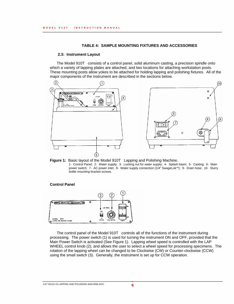
TABLE 4: SAMPLE MOUNTING FIXTURES AND ACCESSORIES 2.3: Instrument Layout
The Model 910T consists of a control panel, solid aluminum casting, a precision spindle onto
which a variety of lapping plates are attached, and two locations for attaching workstation posts. These mounting posts allow yokes to be attached for holding lapping and polishing fixtures. All of the major components of the instrument are described in the sections below.
Figure 1: Basic layout of the Model 910T Lapping and Polishing Machine.
1- Control Panel; 2- Water supply; 3- Locking nut for water supply; 4- Splash basin; 5- Casting; 6- Main power switch; 7- AC power inlet; 8- Water supply connection (1/4” SwageLok™); 9- Drain hose; 10- Slurry bottle mounting bracket screws.
Control Panel
The control panel of the Model 910T controls all of the functions of the instrument during
processing. The power switch (1) is used for turning the instrument ON and OFF, provided that the Main Power Switch is activated (See Figure 1). Lapping wheel speed is controlled with the LAP WHEEL control knob (2), and allows the user to select a wheel speed for processing specimens. The rotation of the lapping wheel can be changed to be Clockwise (CW) or Counter-clockwise (CCW) using the small switch (3). Generally, the instrument is set up for CCW operation.

M O D E L 9 1 0 T I N S T R U C T I O N M A N U A L
CAT 50122-10 LAPPING AND POLISHING MACHINE.DOC 7
2.4: Instrument Setup
Installation of the Model 910T is straightforward. Once the unit has been carefully removed from
it’s packaging, four primary installation procedures are required before the unit is ready for operation. Check the unit to make sure there is no damage to the outer casting, drain basin and hose, or lapping plate. If damage has occurred, contact EMS IMMEDIATELY and report the damage.
2.4.1: Water Supply
The Model 910T is used with a water coolant, which helps to cool the grinding and lapping wheel surface and helps carry off debris and removed material. The rear of the instrument is equipped with ¼” SwageLok™ tube fitting used for mounting the inlet water hose from the main water supply of the laboratory. Install the tube as follows: 1. Insert the ¼” tubing included in the ship kit into the SwageLok™ tube fitting (See Figure 1,
#8). Tubing should be ¼” OD in size. 2. Tighten the nut by turning clockwise approximately ½ turn, or until no water leaks when the
water supply is turned on. 3. Attach tubing to proper water hookup. Water supply is typically de-ionized water, although
this is not necessary to operate the instrument. Water purity is strictly based on the specimen material and cleanliness requirements of the user.
4. Test the water connection by turning on the water supply; ensure the water supply hose (Figure 1, #2) is ON. Water should flow onto the surface of the lapping plate.
2.4.2: Drain Hose
The Model 910T also has a large Tygon hose which extends from the rear of the instrument casting to allow the water, abrasive, or anything else being used on the lapping surface to drain into some type of disposal unit (e.g. sink, waste container). Drainage should conform to local State and Federal environmental guidelines for disposal. A filter is sometimes installed at the end of the hose to prevent contamination of standard water supplies and drainage systems, but should be purchased from an outside source by the user.
2.4.3: Lapping Plate Mounting
Mounting of all lapping plates, no matter which type, is done in the same manner. All lapping plates attach to the spindle adapter which, in turn, is attached to the motor spindle. The lapping plate itself is held onto the spindle using a simple spindle adapter. This spindle adapter is mounted onto the spindle using four screws, and is precisely positioned using two guide pins that are inserted into the base of the spindle. The lapping plate is held into place with three o-ring projections. By applying firm downward pressure, the lapping plate will be firmly seated to the spindle adapter. An audible thump will be heard when this is accomplished.
Below is an illustration showing the mounting of the lapping plate using a spacer. If no spacer is used, omit the mounting instructions for this portion of the instructions.

M O D E L 9 1 0 T I N S T R U C T I O N M A N U A L
CAT 50122-10 LAPPING AND POLISHING MACHINE.DOC 8
Lapping plate
Pin o-ring projections
O-ring projection guide holes
Spindle adapter
Bolts
Lapping plate o-ring
Spindle
Figure 2: Illustration lapping plate mounting to the Model 910T . Installation 1. Ensure that the o-ring is seated properly on the spindle. 2. Place the desired thickness spacer onto the spindle such that the guide pins are aligned to
the guide pin holes. 3. Place the spindle adapter onto the spindle. Ensure that the o-ring is properly seated and that
the four bolts are seated into the spindle. 4. Tighten the four bolts to lock the spindle adapter into place. 5. Place the desired lapping plate onto the spindle adapter by seating the three pin o-ring
projections into the guide holes. Be sure the lapping plate is seated properly. 6. Check that the plate has been seated properly by turning the instrument ON and turning the
lapping wheel ON. The plate should rotate uniformly without any visible wobble. 7. Turn the instrument OFF.
2.4.4: Slurry Drip Bottle Installation
Installation of the slurry drip bottle and mounting bracket is required when semi-automatic
lapping and polishing with an abrasive suspension is desired. A slurry reservoir mounting bracket (01-02224-01) is installed onto the rear of the Model 910T using the slurry bottle mounting screws (See Figure 1). Once the bracket has been installed, the slurry drip bottle is placed with the spout facing the casting, and the drip tube placed next to the water supply tube (See Figure 1). The clamping pressure on the hose determines the feed rate of the slurry.

M O D E L 9 1 0 T I N S T R U C T I O N M A N U A L
CAT 50122-10 LAPPING AND POLISHING MACHINE.DOC 9
2.5: Accessories
The Model 910T can be used with additional accessories that enhance the capability of the instrument. Each is described in the following sections.
2.5.1: 02-02261 Manual Specimen Yoke
The manual specimen yoke is a simple y-shaped yoke designed for use on the Model 910T for holding Lapping and Polishing Fixtures during processing. The manual specimen yoke is used on either the right side or left side of the instrument and holds fixtures when lapping, grinding, or polishing is done. It allows the user to perform semi-automatic lapping operations without the need for holding fixtures by hand.
Installation and use is described below.
1. Install the workstation post (01-02262) onto the desired side of the Model 910T. See Section 2.5.2.
2. Slide the manual specimen yoke over the workstation post. The post should slide through the post mounting hole (#6).
3. Loosen the arm bracket set screw (#4) to allow positioning of the yoke arm bracket (#3). 4. Adjust the width between the idler wheels (#5) to hold the lapping and polishing fixture in
place. The wheels should contact the base of the lapping fixture at about 1/3 the diameter of the fixture.
5. Tighten the arm bracket set screw to lock in the position of the yoke arm bracket. 6. Adjust the position of the manual specimen yoke relative to the lapping plate. 7. Tighten in place with the post clamp (#2).
Figure 3: Illustration of the 02-02261 Manual Specimen Yoke. On the left is the yoke used for
the left side of the Model 910T, and on the right is the yoke used for the right side of the Model 910T. 1- Main bracket, 2- Post clamp, 3- Yoke arm bracket, 4- Arm bracket set screw, 5- Idler wheels, 6- Post mounting hole, 7- Extension bracket, 8- Extension bracket set screw

M O D E L 9 1 0 T I N S T R U C T I O N M A N U A L
CAT 50122-10 LAPPING AND POLISHING MACHINE.DOC 10
2.5.2: 01-02262-01 Workstation Post
The workstation post is designed to attach to the casting of the Model 910T and is used for attaching the manual specimen yoke. The post is attached to the instrument using a set screw and is simple to install. Instructions and use are described below.
1. Select the desired side of the Model 910T for installing the post. 2. Remove the cover on the Model 910T casting which covers the threaded hole. 3. Place the workstation post onto the Model 910T. 4. Attach using the long threaded set screw.
Figure 4: Illustration of the 01-02262 Workstation Post. 1- Post, 2- Set screw hole
2.5.3: Model 92005 Tri-Holder Specimen Mount
The Model 92005 is a special specimen mounting fixture designed to be used with the
manual specimen yoke. It is a multiple specimen fixture designed to hold up to three epoxy or acrylic encapsulated specimens 38 mm (1.5”) in diameter. The fixture is designed for automated specimen grinding and polishing for multiple specimens to increase throughput and efficiency. Specimens are placed into the Tri -Holder and are locked into place using two set screws (#3) located in the base (#1), creating a three point contact on the specimen. Planarizing the three mounted specimens can be done using the Tri-Holder Planarizing Gage (p/n: 01-02141-01).
For increased loading, several options are available for use with the Model 92005. Additional weights can be added to the top plate of the Model 92005 to increase the load applied to the mount (See Figure 7). Another option is to use the Tri-Holder Planarizing Gage. The gage can be placed on top of the fixture and used as an additional weight (See Figure 8). This provides stability with the weight distributed over the entire surface of the holder, as well as providing a smooth track ideal for the manual specimen yoke to rotate the fixture during grinding and lapping operations. A weight spacer can also be used to allow the use of weights coupled with the planarizing gage to increase the total load applied (See Figure 9).
Below are diagrams illustrating the basic setup of the instruments as well as the various modes available for use of the fixture.

M O D E L 9 1 0 T I N S T R U C T I O N M A N U A L
CAT 50122-10 LAPPING AND POLISHING MACHINE.DOC 11
Figure 5: Schematic drawing of Model 92005 Tri-Holder fixture.
1- Center hole ; 2- Specimen mounting hole; 3- Set screws; 4- Base
Figure 6: Drawing showing the use of the Planarizing Gage for positioning specimens in the holder. 1- Planarizing gage; 2- Model 92005 / 92006 base; 3- Specimens; 4- Set screw
Figure 7: Illustration of the fixture using additional weights for increased load during grinding and polishing steps. 1- Weight; 2- Model 92005 / 92006 Base; 3- Specimens; 4- Spacer; 5- Set screws; 6- Set screw / spacer assembly
Figure 8: Schematic drawing showing the use of the Planarizing gage as additional load for the grinding and polishing steps. 1- Planarizing gage; 2- Model 92005 / 92006 holder; 3- Specimens; 4- Set screws; 5- Screw head cap screw.
Figure 9: Drawing illustrating the use of the Planarizing gage in conjunction with the weights to increase the total applied load to the specimens during grinding and polishing. 1- Planarizing gage; 2- Model 92005 / 92006 holder; 3- Specimens; 4- Set screw; 5- Screw spacer assembly; 6- Set screw

M O D E L 9 1 0 T I N S T R U C T I O N M A N U A L
CAT 50122-10 LAPPING AND POLISHING MACHINE.DOC 12
Instructions for Model 92005 1. Place the Planarizing Gage (Figure 6, #1) onto a hard, flat surface. 2. Place the Model 92005 fixture on top of the planarizing gage with the holes aligned with one
another (Figure 6, #2) 3. Insert the specimens (Figure 6, #4) to be ground and polished into the mounting holes
(Figure 6, # located in the fixture. 4. Simultaneously press each sample down so that it is flush with the hard surface. 5. Tighten the set screws (Figure 6, #3) located on the Model 92005 to lock the specimens into
position. 6. Place the fixture onto the Model 910T and adjust the position of the manual specimen yoke. 7. Place the Planarizing Gage onto the Model 92005 fixture and secure with a set screw. This
will act as an additional weight during the lapping procedure (See Figure 8). 8. If additional weight is desired, add a weight to the top of the Planarizing Gage and replace
the screw with a spacer screw assembly which will allow for the additional weight (See Figure 9).
9. Adjust the manual specimen yoke used for rotating the Model 92005 such that the wheels are allowed to guide the fixture on the outer diameter of the Planarizing Gage. This will allow the rotation of the fixture to be a uniform one.
10. Once the desired thickness and finish has been produced on the specimens, remove the fixture from the machine.
11. Loosen only one of the set screws to remove the specimen.
2.5.4: Model 92006 Quad-Holder Specimen Mount
The Model 92006 is a special specimen mounting fixture designed to be used with the manual specimen yoke. It is a multiple specimen fixture designed to hold up to four epoxy or acrylic encapsulated specimens 25-32 mm (0.98-1.25”) in diameter. The fixture is designed for automated specimen grinding and polishing for multiple specimens to increase throughput and efficiency. Specimens are placed into the Quad -Holder and are locked into place using two set screws (#3) located in the base (#1), creating a three point contact on the specimen. Planarizing the four mounted specimens can be done using the Quad-Holder Planarizing Gage (p/n: 01-02143-01).
For increased loading, several options are available for use with the Model 92006. Additional weights can be added to the top plate of the Model 92006 to increase the load applied to the mount (See Figure 7). Another option is to use the Quad-Holder Planarizing Gage. The gage can be placed on top of the fixture and used as an additional weight (See Figure 8). This provides stability with the weight distributed over the entire surface of the holder, as well as providing a smooth track ideal for the manual specimen yoke to rotate the fixture during grinding and lapping operations. A weight spacer can also be used to allow the use of weights coupled with the planarizing gage to increase the total load applied (See Figure 9).

M O D E L 9 1 0 T I N S T R U C T I O N M A N U A L
CAT 50122-10 LAPPING AND POLISHING MACHINE.DOC 13
Figure 10: Schematic drawing of Model 92006 fixture.
1- Center hole ; 2- Specimen mounting hole; 3,4- Set screws; 5- Base
Instructions for Model 92006 1. Place the Planarizing Gage (Figure 6, #1) onto a hard, flat surface. 2. Place the Model 92006 fixture on top of the planarizing gage with the holes aligned with one
another (Figure 6, #2). 3. Insert the specimens to be ground and polished into the mounting holes located in the fixture.
(Figure 6, #2). 4. Simultaneously press each sample down so that it is flush with the hard surface. 5. Tighten the set screws (Figure 10, #3) located on the Model 92006 to lock the specimens into
position. 6. Place the fixture onto the Model 910T and adjust the position of the manual specimen yoke. 7. Place the Planarizing Gage onto the Model 92006 fixture and secure with a set screw. This
will act as an additional weight during the lapping procedure (See Figure 8). 8. If additional weight is desired, add a weight to the top of the Planarizing Gage and replace the
screw with a spacer screw assembly that will allow for the additional weight (See Figure 9). 9. Adjust the manual specimen yoke such that the wheels are allowed to guide the fixture on the
outer diameter of the Planarizing Gage. This will allow the rotation of the fixture to be a uniform one.
10. Once the desired thickness and finish has been produced on the specimens, remove the fixture from the machine.
11. Loosen only one of the set screws to remove the specimen.

M O D E L 9 1 0 T I N S T R U C T I O N M A N U A L
CAT 50122-10 LAPPING AND POLISHING MACHINE.DOC 14
2.5.5: Model 92030 RPM Meter
Knowing the rotational speed of the Model 910T can be advantageous when producing specimens of similar compositions and during process development. The addition of a calibrated RPM meter is helpful in determination of exact speeds and can aid in the calculation of removal rates and abrasive lifetime. The Model 92030 RPM Meter allows the user to monitor wheel speed, store various speeds and various other functions. The addition of the meter requires an additional electronics assembly to be installed in the instrument performed by EMS.
Figure 11: Illustration of the Model 92030 RPM Meter.
1- Main housing; 2- RPM digital display; 3- START button; 4- Range button; 5- Interface cable to Model 910T ; 6- MAINS ON/OFF Switch; 7- AC Inlet

M O D E L 9 1 0 T I N S T R U C T I O N M A N U A L
CAT 50122-10 LAPPING AND POLISHING MACHINE.DOC 15
3.0: Instrument Operation
The information provided in this manual should be used as a guideline for developing a process suitable to the users needs. Basics for grinding and polishing operations will be discussed as well as the parameters used for setting up the instrument and standard operating procedures.
3.1: Lapping and Polishing Basics
Specimen preparation using the Model 910T can generally be characterized in three ways: grinding, lapping and polishing. All three mechanisms are used for material removal, but the application of which greatly depends upon the requirements of the specimen, specimen material, and many other factors.
Grinding can be defined as the rapid removal of material from a specimen either to reduce it to a suitable size or to remove large irregularities from the surface. The grinding wheel or plate typically rotates at a high speed and a coarse (> 20 µm), bonded abrasive is used. Care at the grinding stage is imperative in order to avoid permanent changes in structure or severe sub-surface damage. Damage layers are later removed in lapping and / or polishing steps.
Lapping is the removal of material to produce a smooth, flat, unpolished surface. The lapping plate will rotate at a low (<150 rpm) speed and a medium abrasive particle (10-20µm) is typically used. Lapping removes subsurface damage caused by sawing or grinding and produces the required thickness and flatness. There are primarily two different modes of lapping: free abrasive lapping and fixed abrasive lapping. Free abrasive lapping is when abrasive slurry (suspension) is applied directly to a hard, metallic lapping plate. Fixed abrasive lapping is when an abrasive particle is bonded to a substrate as with abrasive lapping films and papers. The greatest flatness will be achieved with free abrasive lapping due to the rigid surface of the metal plate, although modern abrasive lapping films have comparable results. Abrasive lapping films have abrasive particles bonded to a thin, uniform polyester substrate and are also capable of producing a very flat surface. SiC papers are much thicker than the film and create the potential for rounded edges on the specimen.
Polishing is the removal of material to produce a scratch-free, specular surface using fine (<3 µm) abrasive particles. Polishing is typically done at low speeds using either polishing cloths or abrasive polishing films. As with lapping, polishing can be done with either free or fixed abrasives. Using free abrasives with a polishing cloth is typical when very small amounts of material need to be removed because the flatness of the specimen can be jeopardized. Utilizing a cloth with a very short nap minimizes the rounding of specimens. Final polishing is usually accomplished using a napless polyurethane pad such as MultiTex with 0.05 µm aluminum oxide or non-crystallizing colloidal silica. Abrasive polishing films have grown in popularity as they provide a very firm, uniform surface on which to polish. Abrasive polishing with diamond or aluminum oxide suspensions are characteristically used and are available in particle sizes down to 0.05 µm. Rounding of the specimen edges is less of a concern with abrasive polishing film due to their flatness and uniform thickness.
3.2: Lapping Plate Selection
There are several different lapping plates available for use with the Model 910T and they can be set up in several different ways. Depending upon which stage of preparation the specimen is under, what type of material is being prepared, and the final requirements of the specimen, different lapping plates are used. The following describes each plate in detail and also describes their uses.

M O D E L 9 1 0 T I N S T R U C T I O N M A N U A L
CAT 50122- .DOC 10 LAPPING AND POLISHING MACHINE
3.2.1: Cast Iron Lapping Plates
The cast iron (Cast Fe) lapping plate is designed to be used as a free abrasive lapping wheel, where an abrasive suspension of some type (typically Al2O3 or BC) is applied to the plate surface and performs the lapping action. The cast iron plate is designed to provide supreme flatness and can be continuously re-conditioned (reground to make flat again) using a conditioning ring (01-02221-01). This helps to maintain the flatness of the plate during processing and ensures the specimen is lapped flat.
It is recommended that the user have one plate dedicated to a specific grit size, primarily due to the abrasive particles embedding into the surface of the plate. The cast iron is a very soft metal and allows abrasive particles to embed in the surface, which helps grinding and makes it more efficient but makes it difficult to completely remove abrasive from the previous step. Therefore it is recommended that each grit size used be dedicated to only one wheel.
Several different types of Cast Fe lapping plates are available and are discussed below.
Model LP 920M (Flat Plate) The LP 920M is a flat, Cast Fe plate used for multi-purpose lapping
of many different materials. The flat plate is especially well suited to lapping specimens which have small surface area and lapped with minimum amounts of load. Specimens greater than 1” (25 mm) sometimes create resistance during lapping and can prevent the lapping fixture from rotating.
Model LP 920MC (Concentric Grooved Plate)
The LP 920MC is a Cast Fe plate machine with concentric grooves
in the surface of the plate. These grooves help trap abrasive suspension in them during processing and also reduce the amount of resistance imparted to the specimen during lapping. Large, flat specimens (e.g. 2” (50mm) wafers) are best suited to use on grooved plates to prevent any detrimental effects from friction between the specimen surface and the plate surface.
Model LP 920MR (Radial Grooved Plate)
The Model LP 920MR is a Cast Fe plate machined with radial
grooves in the surface of the plate. These grooves again help trap abrasive suspension in them during processing and also reduce the amount of resistance imparted to the specimen during lapping. Radial grooves help reduce the possibility of scratching the specimen surface and also improve flatness of the plate during lapping.
Model LP 920MS (Spiral Grooved Plate)
The Model LP 920MS is a Cast Fe plate machined with spiral
grooves in the surface of the plate. These grooves, similar to the LP 920MC, both trap abrasive suspension during processing as well as
16

M O D E L 9 1 0 T I N S T R U C T I O N M A N U A L
CAT 50122-10 LAPPING AND POLISHING MACHINE.DOC 17
reduce the resistance created between the specimen/plate interface. Larger wafers greater than 2” (50mm) are well suited to being prepared on these types of plates.
Instructions for use of Cast Fe Lapping Plates 1. Mount the LP 920M Cast Fe plate onto the Model 910T (See Section 2.4.3 for
instructions). 2. Mount the manual specimen yoke onto the Model 910T (See Section 2.5.1 for
instructions). 3. Place the conditioning ring (01-02221-01) onto the Cast Fe plate. 4. Adjust the position of the manual specimen yoke until the idler wheels are extended to 1/3 the
diameter of the conditioning ring and the ring is seated between the center hole and the lapping plate edge. See Figure 12 for diagram.
5. Lock the manual specimen yoke into position. 6. Place about 15 – 20 drops of abrasive slurry inside the slurry ring. Use the abrasive size and
type that will be used with the lapping plate, typically 14 µm. 7. Turn ON the Model 910T . Set the LAP WHEEL speed to 2 on the dial. 8. Check the rotation of the conditioning ring and make sure that it covers the entire lapping
plate surface. The conditioning ring should rotate uniformly and remain in the manual specimen yoke during preparation.
NOTE: During conditioning, the plate should continuously have abrasive suspension applied to the plate. A slurry drip rate of approximately 1 drop every 15-30 seconds is sufficient.
9. Allow the plate to condition for at least 1- 2 hours if the plate has never been used. Typically
the plate should take about 20-30 minutes to condition depending upon the condition of the plate surface.
LAPPING PLATE
MANUAL SPECIMEN YOKE
CONDITIONING RING

M O D E L 9 1 0 T I N S T R U C T I O N M A N U A L
CAT 50122-10 LAPPING AND POLISHING MACHINE.DOC 18
Figure 12: Illustration of the proper setup for conditioning the cast iron lapping plate. The conditioning ring is set to cover ½ of the lapping plate surface while the Manual specimen yoke holds the conditioning ring in place. The ring is rotated as abrasive is fed onto the plate surface, removing material from the lapping plate. This ensures that the plate surface is both flat and conditioned to the proper abrasive particle size used during the lapping process.
3.2.2: Aluminum Lapping Plate
The aluminum lapping plate is an excellent multi-purpose plate. The aluminum plate is commonly used for mounting polishing cloths, metal bonded grinding discs, and abrasive papers. The aluminum plate can also be used as a substrate plate for mounting a glass plate when using non -adhesive abrasive films such as diamond and aluminum oxide. When using non-adhesive backed polishing cloths, the rubber o-ring should be used to hold the cloth onto the surface of the plate. The cloth is extended around the circumference of the plate and the o-ring placed around the outer edge of the plate to hold it in place. The o-ring will sit inside the groove around the outside of the lapping plate. For plain backed papers the metal holding band (01-02254-01) is used to hold papers in place. This eliminates the need for using adhesive backed papers and makes changing grit sizes fast and easy. Mounting Polishing Cloths (Plain Back) 1. Mount the Model LP 920A (aluminum lapping plate) onto the Model 910T . 2. Place the polishing cloth being used onto the surface of the aluminum plate. Be sure that the
polishing cloth is approximately 10” (250 mm) in diameter to allow the cloth to be held in place. Be sure the o-ring seats in the groove provided.
3. Slip the o-ring (0537-047) for the aluminum plate over the polishing cloth. 4. Pull the edges of the polishing cloth to eliminate any wrinkles, bubbles, etc. until the cloth is
smooth over the entire plate surface. Mounting Abrasive Papers 1. Mount the Model LP 920A (aluminum lapping plate) onto the Model 910T . 2. Slip the o-ring (0537-047) for the aluminum plate around the circumference of the plate. Be
sure the o-ring seats in the groove provided. 3. Slide the metal holding band (01-02254) over the abrasive paper and aluminum plate. 4. Push firmly down on the metal holding band until it seats tightly onto the o-ring. Mounting Plain Back Abrasive Films 1. Mount the Model LP 920A (aluminum lapping plate) onto the Model 910T . Make sure the o-
ring is not installed. 2. Place the 8” (200 mm) glass plate onto the surface of the aluminum plate. 3. Using electrical tape, tape down the glass plate to the aluminum plate by running the
electrical tape around the circumference. Half of the tape should cover the edge of the glass plate, while the other half should cover the aluminum plate.
4. Check the surface of the glass plate to make sure there is no electrical tape above the edges. 5. Wet the surface of the glass plate and wipe off with a sponge. Remove any debris or dirt
accumulated on the glass plate. 6. Wet the surface again with water. 7. Place the abrasive film (plastic side down) onto the glass plate. 8. Squeeze out all of the excess water using a rubber squeegee. 9. Check that the film is properly seated (e.g. no overhang).

M O D E L 9 1 0 T I N S T R U C T I O N M A N U A L
CAT 50122-10 LAPPING AND POLISHING MACHINE.DOC 19
Mounting a Glass Plate to the LP 920A 1. Mount the Model LP 920A (aluminum lapping plate) onto the Model 910T. Make sure the o-
ring is not installed. 2. Place the 8” (200 mm) glass plate onto the surface of the aluminum plate. 3. Using electrical tape, tape down the glass plate to the aluminum plate by running the
electrical tape around the circumference. Half of the tape should cover the edge of the glass plate, while the other half should cover the aluminum plate.
4. Check the surface of the glass plate to make sure there is no electrical tape above the edges. 3.2.3: PVC Lapping Plate
The PVC lapping plate is designed for doing chemical polishing. It is constructed of high quality, PVC plastic that is resistant to most chemicals. It provides a solid, high precision plate for doing any chemical polishing. This is for use with the Model 160 Chemical Polishing Fixture, which also is to be used with chemical polishing applications. Although the Model 910T is not chemically resistant, it may be used for VERY SHORT periods of time with MILD chemicals.
NOTE: EMS does not guarantee the Model 910T and it’s ability to handle chemical polishing. Any attempts with chemical polishing are done at the user’s discretion and will result in voiding any and all warranties purchased therein.
3.3: Specimen Processing
The flexibility of the Model 910T allows a multitude of applications and samples to be prepared, with virtually an infinite number of processing steps available to the user. However, basic guidelines apply to a general set of specimens and can be used as a starting point for a particular sample. Remember, this process is a GENERALIZED process and experimentation should be done with a given specimen type. Below are three basic guidelines for specimen preparation of metallographic samples, crystals, and electron microscopy cross sections.
3.3.1: Metallographic Samples
Most metallographic samples (metals) are first encapsulated in an epoxy or phenolic resin of approximately 1” (25 mm) diameter. After this process has been completed, the samples are generally ground and polished to a smooth surface, then chemically etched to reveal the characteristic microstructure. Samples are mounted onto a lapping and polishing fixture (such as the Model 150) and then processed using the aluminum lapping plate coupled with abrasive papers. Typically, the following processing steps are used for the production of many metallographic samples.
Processing Media Abrasive Size SiC Abrasive Paper 240 grit SiC Abrasive Paper 320 grit SiC Abrasive Paper 400 grit SiC Abrasive Paper 600 grit SiC Abrasive Paper 800 grit SiC Abrasive Paper 1000 grit SiC Abrasive Paper 1200 grit

M O D E L 9 1 0 T I N S T R U C T I O N M A N U A L
CAT 50122-10 LAPPING AND POLISHING MACHINE.DOC 20
Nylon Polishing Cloth 6 micron aluminum oxide suspension Cotton Fine Polishing Cloth 3 or 1 micron aluminum oxide suspension MultiTex Polishing Cloth 0.5 and 0.05 micron aluminum oxide suspension
TABLE 5: BASIC SEQUENCE USED FOR PROCESSING METALLOGRAPHIC SAMPLES. 3.3.2: Optical Crystals or Wafers
Optical crystals and wafers generally require gentle techniques to prevent specimen damage such as crack propagation, surface deformation and scratching, and cleaving. In many cases these specimens require tight tolerances and therefore free abrasive lapping with a metal plate is generally used combined with polishing techniques. A basic outline for this type of preparation is given below.
Process Step Processing Media Abrasive Size Lapping Cast Fe Plate 14 micron boron
carbide Rough Polishing Sanypol Polishing Cloth 9 micron diamond
suspension Rough Polishing Sanypol Polishing Cloth 6 micron diamond
suspension Fine Polishing Cotton Fine Polishing Cloth 3 micron diamond
suspension Fine Polishing Cotton Fine Polishing Cloth 1 micron diamond
suspension Final Polishing MultiTex Polishing Cloth 0.5 micron diamond
suspension TABLE 6: BASIC PROCESS FOR PROCESSING OPTICAL CRYSTAL SAMPLES. 3.3.3: Electron Microscopy Cross Sections
Specimen preparation for electron microscopy is generally done with abrasive lapping films
due to their flatness characteristics. Samples are typically mounted onto a Model 590Tripod Polisher® and then polished edge-on to produce a cross section. These types of grinding and polishing steps are usually done with diamond abrasive films at slow speeds. Typical rotation speeds are around 25-200 rpm, with the final stages of polishing done at the lower speed. Usually a glass plate is used for the abrasive films which are held in place using water surface tension between the film and the glass plate. The films are held on by surface tension and are easily removed. A brief outline of the types of diamond film sizes and lapping wheel speeds are described below to use as a general guideline for grinding and polishing SEM and TEM samples.
Processing Step Abrasive Type Wheel Rotation (RPM)
Grinding 30 micron diamond abrasive film 200 Grinding 15 micron diamond abrasive film 150 Rough Polishing 9 micron diamond abrasive film 100 Fine Polishing 3 micron diamond abrasive film 50 Fine Polishing 1 micron diamond abrasive film 20-40 Fine Polishing 0.5 micron diamond abrasive film 20
Final Polishing 0.05 micron colloidal silica on MultiTex Polishing Cloth 20-40

M O D E L 9 1 0 T I N S T R U C T I O N M A N U A L
CAT 50122-10 LAPPING AND POLISHING MACHINE.DOC 21
TABLE 7: BASIC PROCESS FOR PREPARING SEM AND TEM SPECIMENS.
3.4: Standard Operating Procedure
The following instructions refer to the setup of the Model 910T and the instructions for using the instrument.
Checks 1. Make sure the instrument is plugged into the proper electrical outlet. 2. Make sure the proper water installation has been accomplished and no leaks are visible. See
Section 2.4.1. 3. Make sure the proper drainage is installed and operational. See Section 2.4.2. 4. Make sure the slurry drip bottle has been installed properly. See Section 2.4.4.
Procedure 1. Turn on the main power at the rear of the instrument by switching the switch to the up position. 2. Swing the water supply hose to the left so that it is out of the way of the drain basin. Hold the arm
of the water supply hose and turn the thumbscrew counter-clockwise. Once the set screw is loose, the supply hose can be swung to the left.
3. Install the desired lapping plate as described in Section 2.4.3. 4. Place the proper abrasive, lapping film, or polishing cloth onto the lapping plate surface. If using
non-adhesive backed papers or films, use the retaining ring and fit the ring over the outside edge of the lapping plate surface. See Sections 3.2.1 and 3.2.2.
5. Adjust the supply hose to the proper position on the lapping plate. The hose is normally placed at the 12 o’clock position on the lapping wheel.
6. Tighten the thumbscrew on the water supply hose to lock into place. 7. Install the manual specimen yoke to be used for processing. See Section 2.5.1 for detailed
instructions. 8. If using the manual specimen yoke, place the lapping and polishing fixture in place on the lapping
plate. 9. If polishing or free abrasive lapping, fill the slurry drip bottle with the desired abrasive. Make sure
no abrasive is dripping out onto the plate surface. 10. Turn on the control panel power by depressing the ON/OFF button at the control panel. Red
lamp should illuminate to indicate the power is on. 11. Select the lapping wheel speed at which the grinding or polishing operation is to commence. 12. Open the water valve to allow the proper amount of water coolant to flow onto the lapping wheel
surface. Adjust according to the desired flow rate. If using abrasive, adjust the slurry drip bottle to the proper feed rate of approximately 1 drop / 15 seconds.
13. Commence processing of the specimen to the desired thickness and finish. 14. Turn the control panel power to OFF by depressing the ON/OFF button at the control panel. 15. Turn off the water supply. Close the slurry drip bottle if using abrasive. 16. Repeat Steps 2 – 15. 17. Turn of the Main power switch at the rear of the instrument.

M O D E L 9 1 0 T I N S T R U C T I O N M A N U A L
CAT 50122-10 LAPPING AND POLISHING MACHINE.DOC 22
4.0: Maintenance and Service
It is important to maintain the instrument so that it will perform at it’s maximum efficiency. The following is a basic guideline to the necessary maintenance required by the user.
4.1: General Maintenance 1. Do not allow water to overflow in the drain basin. Water damage or electrical damage may result. 2. Make sure that all water connections are installed properly and that none of them leak into the
instrument. 3. Clean off all abrasives from specimen yoke parts, lapping plates, and other components to
prevent excess wear. 4. Do not allow abrasives or water to dry on or around the manual specimen yoke. 5. Make sure the drain hose is properly installed and draining properly. 6. Do not drop the instrument on any hard surface. 7. Do not drop the lapping plates on any hard surface. 8. When using Cast Fe lapping plates, be sure to clean off all abrasive and use a lubricant on the
plate to prevent rust. 4.2 Belt Replacement
In the event that the drive belt is necessary to change, the following instructions describe how to install a new belt.
1. Disconnect the instrument from the main power supply (unplug from the wall). 2. Swing the water supply arm clockwise up against the control panel and tighten the thumbscrew to
lock into place. 3. Remove the manual specimen yoke if installed. 4. Remove the lapping plate from the spindle by rocking the plate back and forth while
simultaneously pulling the lapping plate upwards. 5. Make sure the basin and the drain hose is fully drained with no water or liquid remaining. 6. Loosen the black plastic drain hose bulkhead fitting by gripping the drain hose tightly and rotating
the bulkhead fitting counter-clockwise. 7. Slip the drain hose fitting about 18 inches back along the drain hose. 8. Gently press against the sides of the drain basin to loosen from the bulkhead casting. Carefully
pull the drain basin and hose out as much as allowed. The limit is how far down the drain hose fitting is pushed along the drain hose in Step 6.
9. Remove the four screws that hold the aluminum spindle adapter to the spindle and remove the adapter. Be sure not to allow the o-ring seal to come separated from the spindle.
10. Tip the machine on it’s left side (when facing the instrument panel). 11. Remove the four screws holding the feet onto the black plastic pan onto the bottom of the casting.
Remove the two center screws as well. 12. Remove the black plastic pan. The aluminum housing will now be visible. 13. Four screw assemblies at the right side of the instrument will be visible which hold the motor
mounting bracket to the instrument. This bracket is what creates the tension on the drive belt between the lap pulley (large wheel) and the drive pulley (small wheel at the motor).

M O D E L 9 1 0 T I N S T R U C T I O N M A N U A L
CAT 50122-10 LAPPING AND POLISHING MACHINE.DOC 23
14. Loosen these four screws to release the tension on the worn belt. Slip the belt over the drive pulley and the lap pulley. The belt must be removed from where the drain basin was installed (the round opening on the top of the casting).
15. Place the replacement belt onto the lap pulley. This is done through the top of the casting where the drain basing was installed. Place the other end of the pulley onto the drive pulley. Be sure the belt is still on both pulleys.
16. Adjust the tension of the belt by moving the motor mounting bracket away from the lap pulley. Apply approximately 12 pounds of tension and re-tighten.
17. Turn on the machine to ensure that the pulley is installed correctly. 18. Reverse the previous instructions for re-assembly.
4.3: Motor Assembly 1. Unplug unit from electrical power outlet. 2. Disconnect water supply and check that there is no water left in “Blue Basin” 3. Unit should now be laid down on it’s side. You will require at least 2 to 3 feet of square space. 4. Remove Lap Wheel by undoing the 4 caphead screws that fasten the wheel to Lap Pulley
(Reference to DWG 02-02160). 5. With unit still lying on it’s side, undo the 4 rubber feet and 2 caphead screws and remove the
black plastic pan. (Reference to DWG 02-02160). 6. Now loosen and remove the 6 hexagonal spacers, using a suitable crescent wrench. You will
also have to loosen the 2 caphead screws fastening the mounting bracket (power) 02-02163, to the base plate. (Ref. To DWG 02-02160).
7. It should now be possible to carefully lower the base plate assembly. CAUTION should be taken when doing this, as the base plate is fairly heavy. With the 920 still on it’s side, the base plate will lower to lay down flat on work surface. The P.C.B. and the wiring to it should now be exposed.
8. Disconnect the wires from the bad board and connect them to the new board. You will require a small slotted screwdriver. (Reference to drawing marked “Board Layout”).
9. (Reference to drawing 02-02160) Now loosen screws and washers (Items 18 & 29) and remove them.
10. Install new board and put back items 18 & 29.

M O D E L 9 1 0 T I N S T R U C T I O N M A N U A L
CAT 50122-10 LAPPING AND POLISHING MACHINE.DOC 24
5.0: Safety Safety has been taken into account in the design of the instrument, but using general safety
guidelines is important with any lab equipment. If one follows these general guidelines, safety will not be a problem. 1. Do not work on any electronics, disassemble, or handle electronic components while the instrument is
plugged in. 2. Do not place hands or fingers underneath the lapping wheel during operation. 3. Do not touch electrical components with wet hands. 4. Do not get water or liquids on the electrical components of the instrument. 5. Always check to ensure that the water and drain components are properly installed and operational. 6. Use caution when using hand held fixtures at high lapping wheel speeds. Wear safety goggles if
necessary.