model 8710 - haws corporation · haws corporation performance series model 8710 tempered water...
TRANSCRIPT
HAWS® P/N 0510000453 Rev.5 10/19 Model 8710 Page 1 of 32
1455 Kleppe Lane Sparks, NV 89431-6467 (775) 359-4712 Fax (775) 359-7424 E-mail: [email protected] Website: www.hawsco.com
No. 0510000453(5)
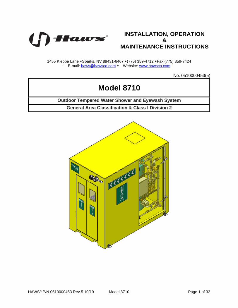
Model 8710
Outdoor Tempered Water Shower and Eyewash System General Area Classification & Class I Division 2
INSTALLATION, OPERATION &
MAINTENANCE INSTRUCTIONS
HAWS® P/N 0510000453 Rev.5 10/19 Model 8710 Page 2 of 32
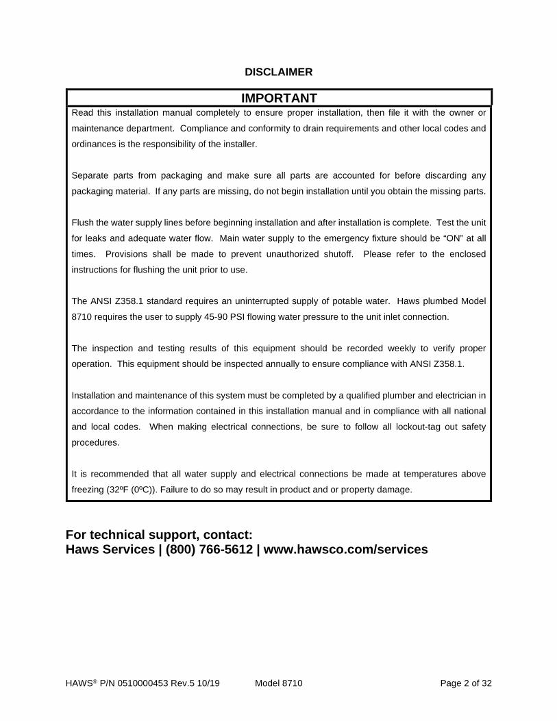
DISCLAIMER
IMPORTANT Read this installation manual completely to ensure proper installation, then file it with the owner or
maintenance department. Compliance and conformity to drain requirements and other local codes and
ordinances is the responsibility of the installer.
Separate parts from packaging and make sure all parts are accounted for before discarding any
packaging material. If any parts are missing, do not begin installation until you obtain the missing parts.
Flush the water supply lines before beginning installation and after installation is complete. Test the unit
for leaks and adequate water flow. Main water supply to the emergency fixture should be “ON” at all
times. Provisions shall be made to prevent unauthorized shutoff. Please refer to the enclosed
instructions for flushing the unit prior to use.
The ANSI Z358.1 standard requires an uninterrupted supply of potable water. Haws plumbed Model
8710 requires the user to supply 45-90 PSI flowing water pressure to the unit inlet connection.
The inspection and testing results of this equipment should be recorded weekly to verify proper
operation. This equipment should be inspected annually to ensure compliance with ANSI Z358.1.
Installation and maintenance of this system must be completed by a qualified plumber and electrician in
accordance to the information contained in this installation manual and in compliance with all national
and local codes. When making electrical connections, be sure to follow all lockout-tag out safety
procedures.
It is recommended that all water supply and electrical connections be made at temperatures above
freezing (32ºF (0ºC)). Failure to do so may result in product and or property damage.
For technical support, contact: Haws Services | (800) 766-5612 | www.hawsco.com/services

HAWS® P/N 0510000453 Rev.5 10/19 Model 8710 Page 3 of 32
TABLE OF CONTENTS Outdoor Tempered Water Shower and Eyewash System ....................................................................... 1 General Area Classification & Class I Division 2 ..................................................................................... 1 DISCLAIMER ................................................................................................................................................ 2 TABLE OF CONTENTS ............................................................................................................................... 3 DESCRIPTION OF PRODUCT ..................................................................................................................... 5 PERFORMANCE SERIES 8710 MODEL CONFIGURATIONS ................................................................... 5 SHIPPING, HANDLING AND STORAGE .................................................................................................... 6 INSTALLATION PROCEDURE .................................................................................................................... 7
Checklist for start-up ............................................................................................................................ 10 Tank Control .......................................................................................................................................... 12 Alarm Modes – US & [CAN] .................................................................................................................. 12 Messages................................................................................................................................................ 13 Real Time Clock (RTC) .......................................................................................................................... 13 Flow Alarms ........................................................................................................................................... 14 Fault Condition Notification ................................................................................................................. 14 Maintenance Required Notification ..................................................................................................... 14 Space Heater .......................................................................................................................................... 15 Summer Mode ........................................................................................................................................ 15 Tank Monitor .......................................................................................................................................... 15 Tank History ........................................................................................................................................... 16 Setting Current Time and Date on the Controller .............................................................................. 16
PREVENTATIVE MAINTENANCE ............................................................................................................. 17 Weekly .................................................................................................................................................... 17 Monthly ................................................................................................................................................... 18 Quarterly ................................................................................................................................................. 18 Annually.................................................................................................................................................. 18
SYSTEM DRAIN AND CHECK PROCEDURE: ......................................................................................... 20 MAINTENANCE, TESTING, REPAIR ........................................................................................................ 23
Booth ................................................................................................................................................... 23 Double Swinging Doors .................................................................................................................... 23 Blending Valve System ..................................................................................................................... 23 Combination Shower/Eyewash ........................................................................................................ 24 Freeze and Scald Valve ..................................................................................................................... 24 Y-Strainers .......................................................................................................................................... 24
TROUBLESHOOTING ................................................................................................................................ 25 SPARE PARTS ........................................................................................................................................... 26 DRAWINGS ................................................................................................................................................ 29
Generalized Installation Drawing (8710.21.31-GA) ............................................................................. 29
HAWS® P/N 0510000453 Rev.5 10/19 Model 8710 Page 4 of 32
Generalized Electrical Schematic (8710.2X.31-E) .............................................................................. 30 Generalized Piping and Instrumentation Diagram (8710.21.31 & 8760.21.31 P&ID) ....................... 30
LIMITED WARRANTY ................................................................................................................................ 32
HAWS® P/N 0510000453 Rev.5 10/19 Model 8710 Page 5 of 32
DESCRIPTION OF PRODUCT
Haws Corporation Performance Series model 8710 tempered water booth is a foam-insulated, fiberglass
encapsulated structure. The bright yellow fiberglass is waterproof, chemically resistant, and protected with
UV inhibitors for a long-lasting finish. Large green graphics identify the building as an emergency
shower/eyewash station and assist in guiding the user to the double swing doors. The interior is heated
and illuminated for user safety and comfort.
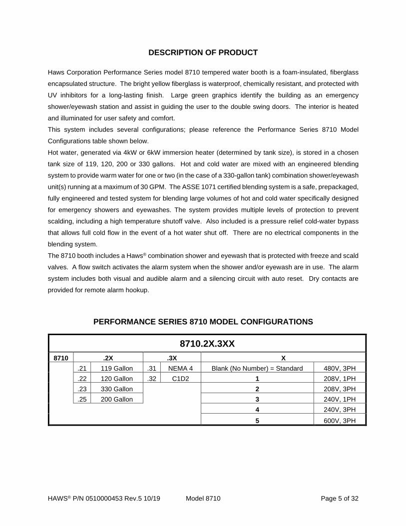
This system includes several configurations; please reference the Performance Series 8710 Model
Configurations table shown below.
Hot water, generated via 4kW or 6kW immersion heater (determined by tank size), is stored in a chosen
tank size of 119, 120, 200 or 330 gallons. Hot and cold water are mixed with an engineered blending
system to provide warm water for one or two (in the case of a 330-gallon tank) combination shower/eyewash
unit(s) running at a maximum of 30 GPM. The ASSE 1071 certified blending system is a safe, prepackaged,
fully engineered and tested system for blending large volumes of hot and cold water specifically designed
for emergency showers and eyewashes. The system provides multiple levels of protection to prevent
scalding, including a high temperature shutoff valve. Also included is a pressure relief cold-water bypass
that allows full cold flow in the event of a hot water shut off. There are no electrical components in the
blending system.
The 8710 booth includes a Haws® combination shower and eyewash that is protected with freeze and scald
valves. A flow switch activates the alarm system when the shower and/or eyewash are in use. The alarm
system includes both visual and audible alarm and a silencing circuit with auto reset. Dry contacts are
provided for remote alarm hookup.
PERFORMANCE SERIES 8710 MODEL CONFIGURATIONS
8710.2X.3XX 8710 .2X .3X X
.21 119 Gallon .31 NEMA 4 Blank (No Number) = Standard 480V, 3PH
.22 120 Gallon .32 C1D2 1 208V, 1PH
.23 330 Gallon
2 208V, 3PH .25 200 Gallon 3 240V, 1PH
4 240V, 3PH 5 600V, 3PH
HAWS® P/N 0510000453 Rev.5 10/19 Model 8710 Page 6 of 32
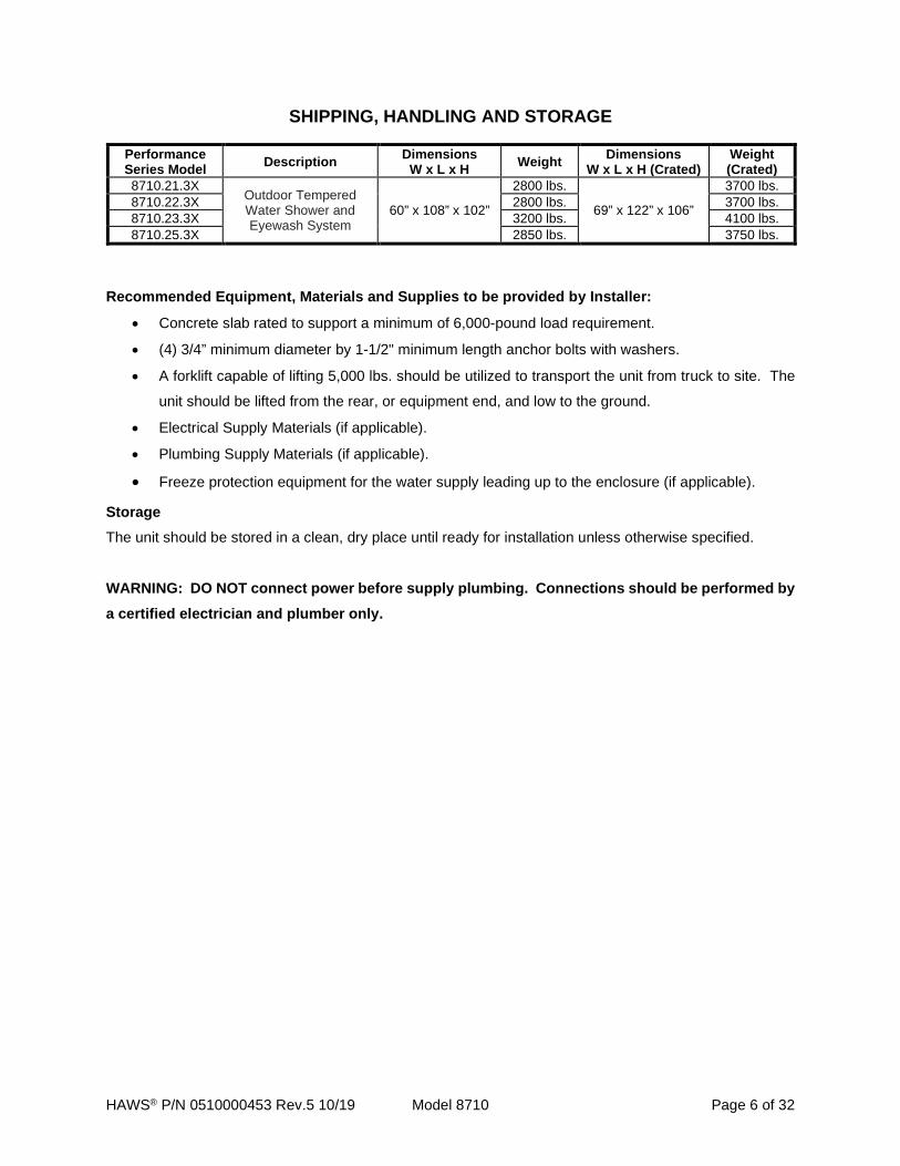
SHIPPING, HANDLING AND STORAGE
Performance Series Model Description Dimensions
W x L x H Weight Dimensions W x L x H (Crated)
Weight (Crated)
8710.21.3X Outdoor Tempered Water Shower and Eyewash System
60” x 108” x 102”
2800 lbs.
69” x 122” x 106”
3700 lbs. 8710.22.3X 2800 lbs. 3700 lbs. 8710.23.3X 3200 lbs. 4100 lbs. 8710.25.3X 2850 lbs. 3750 lbs.
Recommended Equipment, Materials and Supplies to be provided by Installer:
• Concrete slab rated to support a minimum of 6,000-pound load requirement.
• (4) 3/4” minimum diameter by 1-1/2" minimum length anchor bolts with washers.
• A forklift capable of lifting 5,000 lbs. should be utilized to transport the unit from truck to site. The
unit should be lifted from the rear, or equipment end, and low to the ground.
• Electrical Supply Materials (if applicable).
• Plumbing Supply Materials (if applicable).
• Freeze protection equipment for the water supply leading up to the enclosure (if applicable).
Storage The unit should be stored in a clean, dry place until ready for installation unless otherwise specified.
WARNING: DO NOT connect power before supply plumbing. Connections should be performed by a certified electrician and plumber only.

HAWS® P/N 0510000453 Rev.5 10/19 Model 8710 Page 7 of 32
INSTALLATION PROCEDURE
a. Remove unit from crate.
b. The unit should be secured on a level site, using the supplied brackets and suitable anchoring
devices. Suggested anchoring devices are 3/4” minimum diameter by 1-1/2" minimum length
anchor bolts with washers.
c. If the booth is to be placed over a drain, the drain should be able to handle a flow of 35 GPM;
otherwise, the slab should be made to allow the water to drain out the sides and away from the
booth (see Figure 1). The unit discharges hundreds of gallons of water, which can cause significant
property damage if not drained properly.
Figure 1. Example of Slab with Drain Trough
WARNING: Failure to allow water to drain may result in premature failure of booth, voiding of product warranty, and property damage. (See System Drain and Check Procedure on page 20)
d. The expansion tank should be pre-charged with compressed air to a pressure equal to the water
supply pressure. An air fitting (Schrader valve) is accessible on the top of the expansion tank,
under the plastic cap (see Figure 2).
HAWS® P/N 0510000453 Rev.5 10/19 Model 8710 Page 8 of 32
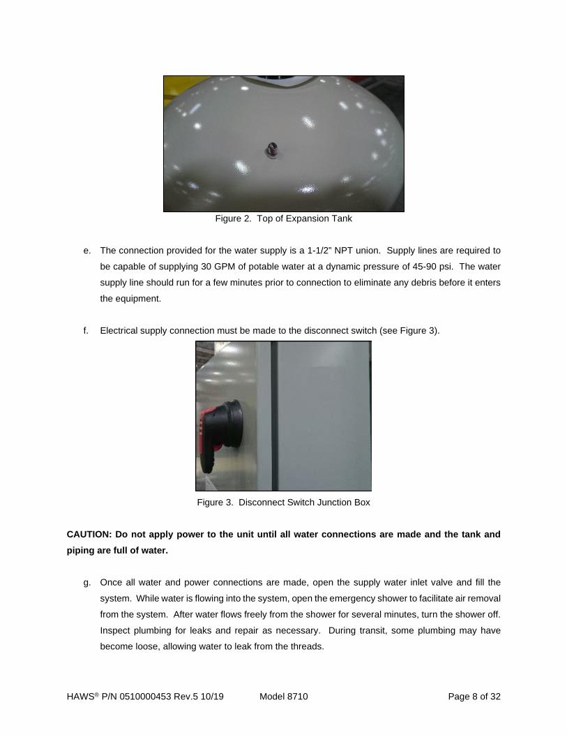
Figure 2. Top of Expansion Tank
e. The connection provided for the water supply is a 1-1/2” NPT union. Supply lines are required to
be capable of supplying 30 GPM of potable water at a dynamic pressure of 45-90 psi. The water
supply line should run for a few minutes prior to connection to eliminate any debris before it enters
the equipment.
f. Electrical supply connection must be made to the disconnect switch (see Figure 3).
Figure 3. Disconnect Switch Junction Box
CAUTION: Do not apply power to the unit until all water connections are made and the tank and piping are full of water.
g. Once all water and power connections are made, open the supply water inlet valve and fill the
system. While water is flowing into the system, open the emergency shower to facilitate air removal
from the system. After water flows freely from the shower for several minutes, turn the shower off.
Inspect plumbing for leaks and repair as necessary. During transit, some plumbing may have
become loose, allowing water to leak from the threads.
HAWS® P/N 0510000453 Rev.5 10/19 Model 8710 Page 9 of 32
CAUTION: Before turning on the power, close all electrical boxes.
h. At this point the power can be turned on. The tank water must be allowed to heat up before the
blending system will function properly. Heating can take up to 12 hours, depending on supply water
temperature and the size of immersion heater and tank. The area/alarm light may blink until tank
temperature set point is reached.
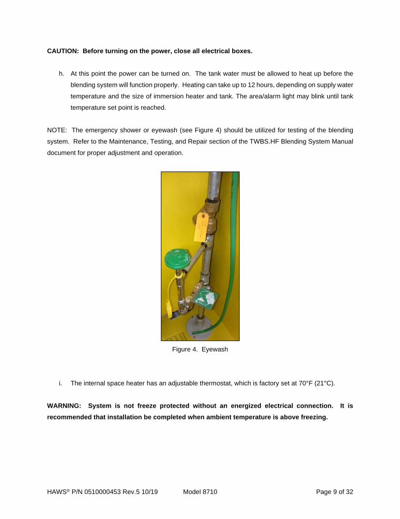
NOTE: The emergency shower or eyewash (see Figure 4) should be utilized for testing of the blending
system. Refer to the Maintenance, Testing, and Repair section of the TWBS.HF Blending System Manual
document for proper adjustment and operation.
Figure 4. Eyewash
i. The internal space heater has an adjustable thermostat, which is factory set at 70°F (21°C).
WARNING: System is not freeze protected without an energized electrical connection. It is recommended that installation be completed when ambient temperature is above freezing.

HAWS® P/N 0510000453 Rev.5 10/19 Model 8710 Page 10 of 32
Checklist for start-up
CHECKLIST Complete OK
Inspector Initials
Pre-connection Check Check all components for any connections or connectors that may have loosened during
shipping.
System Flush (All Electrical Power off for System Flush) Verify that a minimum of 45 psi and maximum 90 psi is supplied to the inlet of the hot water
tank.
Drain is attached and able to handle a flow of 35 GPM. System water supply is connected and all water supply valves opened. Water is clear and free of any contamination, particles, or discoloration. Connections System is charged with water and all air is evacuated from the system. Expansion tank Schrader valve is charged with air equal to water static inlet pressure. Connect remote monitoring via plant control system (if applicable). Applying Power to the System Verify that the proper voltage is present. Verify that equipment ground is properly connected. Apply power to the system. Verify that the space heater thermostat is set to 70º F (21ºC). Increase the thermostat set
point and verify that the heater is producing heat. Return the thermostat to 70ºF.
The tank heater set point is preset in the program. It may take up to 12 hours for the tank to
reach the operating temperature. Once the tank has reached operating temperature for a
minimum of 1 hour, press the “↑” arrow and record these values in the chart provided in the
Tank Monitor section of the program narrative included in this manual.
Verify that interior and exterior lights are illuminated (if equipped). The exterior light may
flash off for 1 second at 5 second intervals until the tank has reached operating
temperature. See Logic Narrative for more information.
HAWS® Shower and Eye/Facewash Flow water through an eyewash or shower. Verify that the exterior light flashes at 1 second intervals and that the audible alarm sounds. Press the alarm silence button and verify that the exterior light is flashing, and the audible
alarm is silent.
Deactivate the shower or eyewash that is active, verify that the exterior light is not flashing,
and that the audible alarm is silent.
Blending Valve When shower is activated read the center temperature gauge directly above the blending
valve to ensure to the readout is 85ºF (29ºC) ± 5º.
Programmable Logic Controller Display Set the current time and date in the controller (see instructions on page 16).

HAWS® P/N 0510000453 Rev.5 10/19 Model 8710 Page 11 of 32
LOGIC DIAGRAM AND NARRATIVE
The program allows for monitoring and controlling booth and tank temperatures. When no faults are
present, the tank temperature, booth temperature, tank heater status, and flow status are displayed (see
Figure 5). There are alarm points that are continuously monitored. These alarms are shown on the display
as long as the fault is active. Alarm conditions may also be monitored by connecting to a Distributed Control
System (DCS) via interposing relays and terminals provided. See generalized electrical schematic for
details (page 30). A fault history is also provided to assist in monitoring the system performance.
Additionally, the tank heater performance can be monitored to assist in determining when maintenance is
required.
Figure 5. PLC Display
Accessing the different functions is accomplished by depressing the appropriate key(s) on the display. The
table below lists the key functions:
Key Function ← Display Fault History ↑ Display Tank Heater Monitor → Display Current Time ↓ Display Current Date 0 Reset High Tank Temp Alarm
0 & 2 Local Alarm Light Function (Off) 1 Reset High Booth Temp Alarm
1 & 2 Start Summer Mode 1 & 3 Local Alarm Light Function (On) 3 & 4 Return from Summer to Normal Mode
Shift + 5 View Time to Preventative Maintenance Shift + 9 Toggle Preventative Maintenance Feature On/Off

HAWS® P/N 0510000453 Rev.5 10/19 Model 8710 Page 12 of 32
The following table lists the inputs and outputs used in the system.
NOTE: For model specific program, please contact Haws Services at 1-800-766-5612.
Input Function Output Function I-00 Flow Switch * Q-00 Tank Heater Contactor I-01 Horn Silence Button * Q-01 Space Heater Contactor * I-02 Level Switch Q-02 Alarm Light * I-03 Booth Thermostat * Q-03 Horn *
AI-02 Tank Temperature Thermocouple Q-04 (TC Q-00) Customer Contact (Trouble) AI-03 Booth Temperature Thermocouple * Q-05 (TC Q-01) Customer Contact (Flow) *
*Not used on some models
The program consists of a series of charts (sub-routines) that are grouped according to function. Each
chart will be discussed in the following sections.
Tank Control When the tank temperature is below 163°F (72°C), or 144ºF (62ºC) for Canada, the tank heater contactor
will close and the heater elements will be energized. When the temperature rises above 166°F (74°C), or
146ºF (63º) for Canada, the contactor will open and the element will become de-energized.
A low-level condition or an over temperature condition (that has not been addressed) will prohibit the
contactor from closing even if the temperature is below the set point. If the tank thermocouple reading falls
below 32°F (0°C) a potential thermocouple failure is present and the tank heater contactor will not close.
The customer trouble alarm contacts are monitored in this section of the program. The following conditions
will de-energize output Q-04 (customer contact trouble) when a potential fault is present:
Alarm Modes – US & [CAN] Low Booth Temperature under 47°F (8°C) & [47°F (8°C)]
High Booth Temperature over 85°F (29°C) & [85°F (29°C)]
High Booth Temperature over 95°F (35°C) & [95°F (35°C)] REQUIRES MANUAL RESET
Low Tank Temperature under 155°F (68°C) & [135°F (57°C)]
High Tank Temperature over 168°F (76°C) & [150°F (66°C)]
High Tank Temperature over 175°F (79°C) & [155°F (68°C)] REQUIRES MANUAL RESET
Low Tank Level
NOTE: Each alarm mode will display an alarm message on the PLC display and only the external light will
flash once every 5 seconds. The high temperature alarms for the tank and booth are designed to give a
warning by displaying an alarm message, changing the state of the customer contacts, and flashing the

HAWS® P/N 0510000453 Rev.5 10/19 Model 8710 Page 13 of 32
exterior light once every 5 second- intervals, 5 degrees before the temperature rises to a point that requires
a manual reset of the heating equipment. Should the alarm not be addressed before reaching the high set
point, then the system will require additional attention and a manual reset.
Messages The display messages are controlled by the program. When no alarm modes are present, the display will
present the following conditions:
Tank Heater On (when active)
Flow Switch On (when active)
Tank Temperature
Booth Temperature or Summer Mode Active
When a single alarm mode, also called fault condition, is present, the display will indicate which alarm mode
is present. If more than one alarm exists, the display will cycle through each alarm at 4 second intervals.
Each message will automatically clear when the condition is no longer active or when the corrective action
has been taken. This program also records a message to the “Fault History” chart, which will assign the
time and date when the alarm occurred using the Real Time Clock (RTC) module. Timer counter (TC-05
in conjunction with TC-06) will keep track of the 4 second timing intervals and advance the message display
to the next active alarm (if present).
Real Time Clock (RTC) The RTC module is used to record the date and time for the Fault History (alarm modes) and auto-return
to Winter Mode.
NOTE: If “NO RTC” is shown on PLC display (see Figure 6), remove RTC module by disconnecting from
PLC, re-attach, and cycle the power. If “NO RTC” is still shown, please contact Haws Services at 1-800-
766-5612 as you may need a replacement part.
Figure 6. No RTC - Real Time Clock Display
HAWS® P/N 0510000453 Rev.5 10/19 Model 8710 Page 14 of 32
Fault History
The fault history chart keeps track of the time and date of the last occurrence of each alarm. When the “left
arrow” key is depressed, the time and date of each alarm will be listed on the display. There will be a 4
second delay before the first alarm is displayed. Each alarm will be listed for 4 seconds if the “left arrow”
key is depressed. The time and date of each alarm are stored in registers R-004 through R-021. Once the
“left arrow” key is released the display will return to the normal condition display if no alarms are present.
If there are alarm modes in the system, the display will return to the alarm mode display when the “left
arrow” key is released.
Flow Alarms Flow is monitored via a flow switch connected to I-00. When the flow switch is activated, output Q-05
(customer contact flow) will de-energize and engage the customer flow contacts. The flow switch will also
energize the horn via Q-03. The exterior light is also controlled in this chart. The exterior light remains on
during normal operation. When flow is detected, the exterior light will flash on and off at 1 second intervals.
Fault Condition Notification If a fault is active and there is no flow detected, the light will flash once every 5 seconds. This function
gives the user an indication of a fault condition if the unit is not connected to plant Distributed Control
System (DCS) via dry contacts provided on the electrical panel layout. To properly connect DCS to dry
contacts, please refer to the model-specific electrical schematic. It is possible to override this function by
simultaneously depressing the “0” and “2” key. Flag F-026 controls this function. It is set as retentive to
maintain the selection after a power outage. These intervals are controlled by TC-00 through TC-04.
NOTE: If a model-specific electrical schematic is not present or additional information is required to connect
DCS to unit, please contact Haws Services at 1-800-766-5612.
Maintenance Required Notification On units containing the “Preventative Maintenance Required” notification feature, the area light will flash
once every 10 seconds when preventative maintenance is required. The notification is factory set to activate
after one year of operation and reactivates each following year.
The operating procedure is as follows:
• To view remaining time until Preventative Maintenance is required, press Shift + 5
• To toggle Preventative Maintenance Required feature on/off, press Shift + 9
o To reset the timer, turn the Preventative Maintenance Required feature off then back on.
The timer will start from 0.
o On/off toggle can also be triggered by the following push button sequence using the alarm
horn silence button.
HAWS® P/N 0510000453 Rev.5 10/19 Model 8710 Page 15 of 32
Press 3 times within 2 seconds, wait 2-5 seconds, and press 3 times within 2
seconds
o Activation of the Preventative Maintenance Required Feature is indicated by 3 short flashes
of the area light accompanied by 3 blips of the alarm horn.
o Deactivation of the Preventative Maintenance Required Feature is indicated by 4 short
flashes of the area light accompanied by 4 blips of the alarm horn.
Space Heater This space heater control program controls the function of the space heater on units designed for use in
non-classified locations. The booth thermostat is connected to I-03, which will engage the space heater
contactor (Q-01). An excessive booth temperature may cause the scald valve to relieve if the booth
temperature approaches 95°F (35°C). The space heater will not operate if the controller detects a
temperature over 85°F (29°C). The space heater will also not operate if the unit has been placed in
“Summer Mode”. If the thermocouple connected to AI-03 detects a temperature over 85°F (29°C), a
message will be displayed indicating that the booth has exceeded 85°F (29°C). This alarm will automatically
reset if the temperature falls to below 83°F (28°C).
A booth temperature over 95°F (35°C), F-011 will set and trigger the “Booth High Temperature +10” fault
alarm. This alarm requires someone to physically reset the alarm by depressing the “1” key on the keypad
after the temperature falls below 90°F (32°C).
Summer Mode The summer mode chart controls the “Summer Mode” function to override the space heater controls.
Simultaneously pressing the “1” and “2” key will activate “Summer Mode” and simultaneously pressing the
“3” and “4” key will deactivate this function. If a temperature less than 40°F (4°C) is detected by the
thermocouple connected to input AI-03, “Summer Mode” will automatically deactivate by setting flag F-025.
This function is also deactivated automatically between September 1 and April 1.
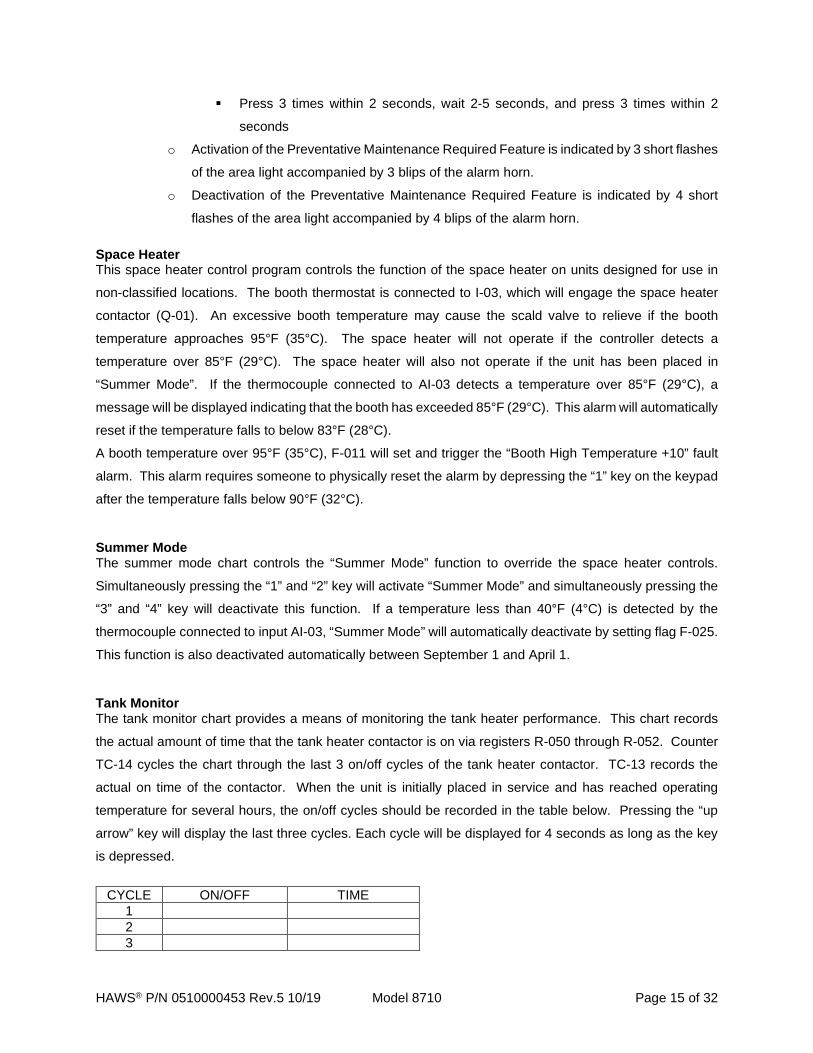
Tank Monitor The tank monitor chart provides a means of monitoring the tank heater performance. This chart records
the actual amount of time that the tank heater contactor is on via registers R-050 through R-052. Counter
TC-14 cycles the chart through the last 3 on/off cycles of the tank heater contactor. TC-13 records the
actual on time of the contactor. When the unit is initially placed in service and has reached operating
temperature for several hours, the on/off cycles should be recorded in the table below. Pressing the “up
arrow” key will display the last three cycles. Each cycle will be displayed for 4 seconds as long as the key
is depressed.
CYCLE ON/OFF TIME
1 2 3

HAWS® P/N 0510000453 Rev.5 10/19 Model 8710 Page 16 of 32
These values can be checked on a routine basis. If the amount of time that the tank heater is on has
increased, it may be an indication that the tank heater needs service or repair.
Tank History This tank history chart controls the display messages recorded by the tank monitor chart. TC-15 sets the
time that each message is displayed. TC-16 is used to increment from “Heater on time 1” through “Heater
on time 3”.
Setting Current Time and Date on the Controller 1. Press the “SHIFT” and “OK” buttons to enter the menu.
2. Press “4” to enter setup.
3. Press “1” to set date or “2” to set time.
4. After date or time is set, press the “SHIFT” and “↑” key to return to setup menu.
The Time and Date can be verified by pressing the “→” or “↓” keys while in the normal operating screen.
HAWS® P/N 0510000453 Rev.5 10/19 Model 8710 Page 17 of 32
PREVENTATIVE MAINTENANCE
Weekly • Verify the tank temperature readout on the display reads 165ºF ± 2ºF (74ºC ± 1ºC) and 145°F ±
2ºF (63°C ± 1°C) for Canada (see Figure 5).
• Verify area lights located inside and outside the booth are operational.
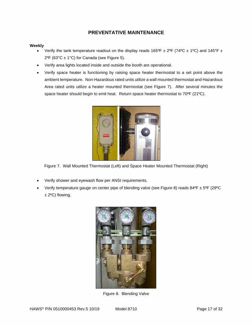
• Verify space heater is functioning by raising space heater thermostat to a set point above the
ambient temperature. Non-Hazardous rated units utilize a wall mounted thermostat and Hazardous
Area rated units utilize a heater mounted thermostat (see Figure 7). After several minutes the
space heater should begin to emit heat. Return space heater thermostat to 70ºF (21ºC).
Figure 7. Wall Mounted Thermostat (Left) and Space Heater Mounted Thermostat (Right)
• Verify shower and eyewash flow per ANSI requirements.
• Verify temperature gauge on center pipe of blending valve (see Figure 8) reads 84ºF ± 5ºF (29ºC
± 2ºC) flowing.
Figure 8. Blending Valve

HAWS® P/N 0510000453 Rev.5 10/19 Model 8710 Page 18 of 32
Monthly • Verify eyewash flows. Alarm light and horn should activate when water is flowing. Verify that
remote alarms connected to plant controls are functioning.
• Verify shower flow. Alarm light and horn should activate when water is flowing. Verify that remote
alarms connected to plant controls are functioning.
• Check for evidence of leakage on freeze and scald valves.
• Verify correct operation of Blending valve. See Maintenance, Testing, and Repair section located
on page 23.
Quarterly • Flush Y–strainers (if installed)
Annually • Check tank heater for excessive mineral build up on heating coils. Clean or replace if necessary.
• Check operation of tank level switch (see Figure 9).
• Check condition of tank anode(s). Replace if necessary.
• Drain tank and verify level switch operation.
Figure 9. Level Switch
• All emergency showers and eye/face washes shall be inspected annually to assure conformance
of ANSI Z358.1. This includes, but not limited to, proper installation, accessible locations, proper
flow rate and temperature of flushing fluid. Please refer to the most current standards document
for more information.

HAWS® P/N 0510000453 Rev.5 10/19 Model 8710 Page 19 of 32
NOTE: If the blending valve temperature reading is incorrect, adjust the blending valve by turning the
socket head cap screw located on the bottom of the center section of the valve body. Turning the screw
clockwise will lower the outlet temperature, while counterclockwise will raise the outlet temperature (see
Figure 10). Maximum outlet temperature is approximately 85°F. Outlet temperature will be measured most
accurately by the temperature gauge when water is flowing through the valve.
Figure 10. Blending Valve
HAWS® P/N 0510000453 Rev.5 10/19 Model 8710 Page 20 of 32
SYSTEM DRAIN AND CHECK PROCEDURE:
WARNING! System contains HOT water! Failure to DISCONNECT POWER AND ALLOW WATER IN HOT WATER TANK TO COOL sufficiently prior to draining may cause SEVERE INJURY OR DEATH! Always follow safe Lock Out – Tag Out procedures.
1. Turn off power at system disconnect switch. Lock Out and Tag Out according to your company’s
procedures.
2. Allow system hot water tank to cool below 100°F. Cooling could take many hours depending on
the ambient temperature. This process can be sped up by opening the shower and allowing the
blending valve to consume the hot water from the tank in the blending process. While the shower
is running, monitor the blending valve hot water inlet mechanical temperature gauge. When the
blending valve hot water inlet temperature gauge drops below 100°F WHILE FLOWING, the tank
temperature will be low enough to facilitate safe system draining.
a. If you will be running the shower to drop the tank temperature, this may be an appropriate
opportunity to also perform an annual test of the shower for ANSI Z358.1 compliance for
flow and pattern. If so, be aware that full 15-minute duration of tepid water may be modestly
shortened because the tank heater would not be operating.
3. When the hot water tank has cooled sufficiently, shut off the shower if it has been activated, and
turn off the main inlet water supply ball valve located inside the booth on the water supply line. This
is a lockable ball valve and Haws recommends locking this valve in the off position any time the
system is to be drained.
4. If necessary, connect a drain hose to the drain elbow outside the booth and route to a safe drain
location (or to the shower drain if unit is connected to a drain pipe). Do not open drain valve until
step 8.
5. Confirm that the power is disconnected.
6. Unscrew and remove the cover on the Level Switch (Figure 9).
7. Using a multimeter, check continuity across the wired terminal block between the pin labeled “C”
and the pin labeled “NC”. If the tank is full, as it should be at this point, the multimeter should
indicate electrical continuity exists between these two pins. (Note this Double Pole, Double Throw
switch has two identical terminal blocks and testing should be done on the one that is wired.) If the

HAWS® P/N 0510000453 Rev.5 10/19 Model 8710 Page 21 of 32
tank has been heating properly, this test SHOULD be positive. If not, check the connections and
confirm the tank is full.
8. Open the system drain valve inside the booth near the drain outlet elbow in the back wall to drain
the system. To speed up draining, allow additional air into the tank by opening the ball valve on
the y-strainer in the hot water line and between the top of the tank and the hot side of the blending
valve. Continue until water stops draining.
9. Using a multimeter, check continuity across the wired terminal block between the pin labeled “C”
and the pin labeled “NC”. If the tank is empty (or below the level of the switch), as it should be at
this point, the multimeter should indicate NO electrical continuity exists between these two pins.
(Note this Double Pole, Double Throw switch has two identical terminal blocks and testing should
be done on the one that is wired.) If the multimeter indicates continuity DOES exist when the tank
is empty, the float may be stuck in the up position, which would require removal and cleaning and/or
replacement of the level switch.
10. For 119, 120, and 200-gallon tanks, remove and inspect the tank “sacrificial” anode rod(s) for
condition. These rods are designed to corrode and deteriorate before other less reactive surfaces
in the system, so some corrosion is normal. If the stainless-steel core can be seen or the rod is
grossly deteriorated, it should be replaced.
11. For 119, 120, and 200-gallon tanks, consider removing and inspecting the tank heater for excessive
mineral buildup on the heater coils. In particular, if significant debris is noticed in the drain water,
the local water is known to be “hard” or have high mineral content, or tank heater monitoring
indicates more and more frequent cycling, consider removing and inspecting/cleaning the
immersion heater. (Electrical disconnection and re-connection should be done by a qualified
electrician) Contact Haws Services for questions at 1-800-766-5612.
12. For 330-gallon tanks, the manway can be carefully removed to allow internal inspection of the
anode rods and immersion heater coils without removal. The tank bottom should also be inspected
for excessive debris and cleaned if necessary. NEVER ATTEMPT TO ENTER THE TANK!
CAUTION: When inspecting, take care not to drop anything in the tank as the glass lining in the tank could be permanently damaged! Remove and replace any excessively deteriorated anode rods. If inspection of the heater coils
indicates excessive mineral buildup, remove the heater for cleaning or replacement. (Electrical
disconnection and re-connection should be done by a qualified electrician.)
Contact Haws Services for questions at 1-800-766-5612.

HAWS® P/N 0510000453 Rev.5 10/19 Model 8710 Page 22 of 32
13. Now is also a good time to open and clean out the Y-strainers (one in the inlet water line and one
in the hot water line).
14. When maintenance is complete and any components removed have been replaced, close the
system drain valve and the ball valve on the hot line Y-strainer if it was opened.
15. Unlock and open the inlet water supply valve and allow the system to fill. Opening the shower can
facilitate the exit of air from the system.
16. When the system is full of water, follow appropriate Lock Out-Tag Out procedures to unlock and
turn on the system disconnect switch to restore power to the unit.
17. Allow time for the system to come up to temperature (up to 12 hours) and ensure that all alarms
are clear.
HAWS® P/N 0510000453 Rev.5 10/19 Model 8710 Page 23 of 32
MAINTENANCE, TESTING, REPAIR
Booth The foam insulated booth is coated with a fiberglass membrane. Should cleaning be necessary, a
mixture of water with household glass cleaner or rubbing alcohol can be used. For repairs to small
holes in the booth, Sikaflex 1A Construction Sealant, silicone, or a similar sealant can be used to
seal openings in the booth’s surface. If foam is exposed, a resin can be applied to protect it from
the elements. Damaged or removed sections of wood can be replaced with “Bondo” or other
shaping material, and other holes, gouges, or tears in the membrane can be patched using
fiberglass.
WARNING: Failure to patch or fill any holes or punctures to booth may result in premature failure of booth and void the product warranty.
Double Swinging Doors CAUTION: KEEP FINGERS AWAY FROM PINCH POINTS!
The doors have been adjusted at the factory with proper tension to allow for closure of doors.
Should doors need to be adjusted, tension can be changed by adjusting the spring tensioner at the
top or bottom of the spring loaded double acting hinges.
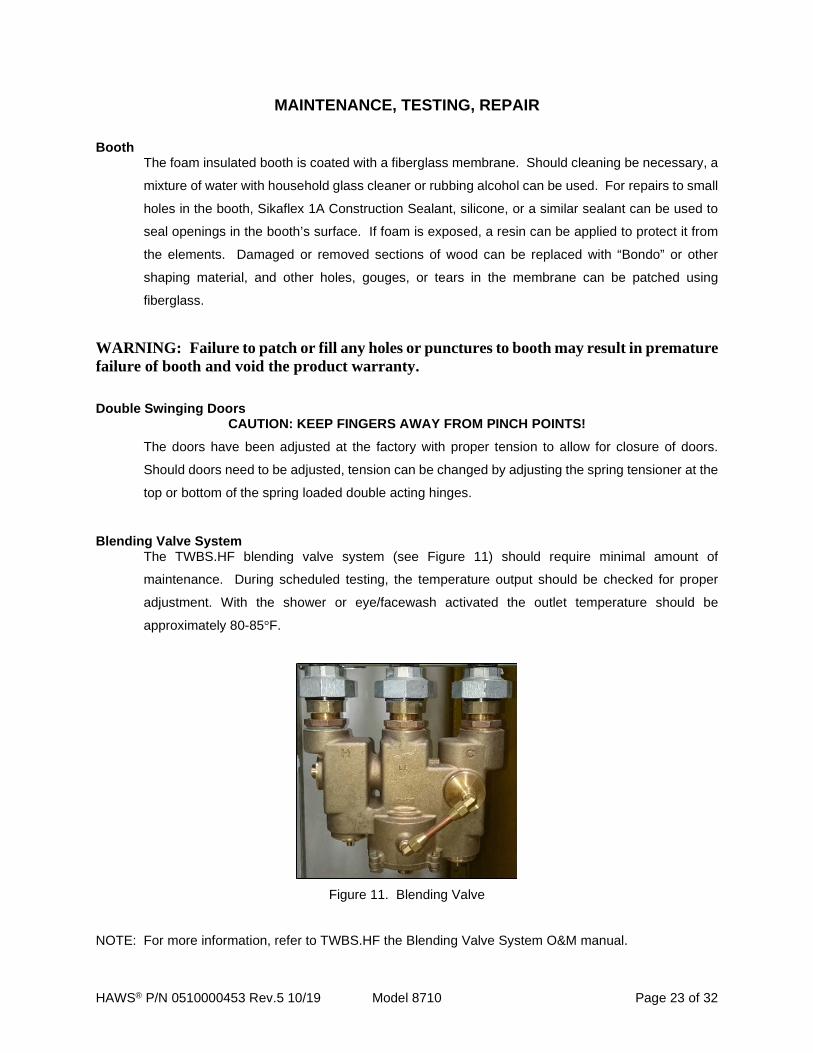
Blending Valve System The TWBS.HF blending valve system (see Figure 11) should require minimal amount of
maintenance. During scheduled testing, the temperature output should be checked for proper
adjustment. With the shower or eye/facewash activated the outlet temperature should be
approximately 80-85°F.
Figure 11. Blending Valve
NOTE: For more information, refer to TWBS.HF the Blending Valve System O&M manual.
HAWS® P/N 0510000453 Rev.5 10/19 Model 8710 Page 24 of 32
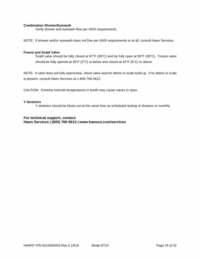
Combination Shower/Eyewash Verify shower and eyewash flow per ANSI requirements.
NOTE: If shower and/or eyewash does not flow per ANSI requirements or at all, consult Haws Services.
Freeze and Scald Valve Scald valve should be fully closed at 87°F (36°C) and be fully open at 95°F (35°C). Freeze valve
should be fully opened at 36°F (2°C) or below and closed at 42°F (6°C) or above.
NOTE: If valve does not fully open/close, check valve seat for debris or scale build up. If no debris or scale
is present, consult Haws Services at 1-800-766-5612.
CAUTION: Extreme hot/cold temperatures in booth may cause valves to open.
Y-Strainers Y-strainers should be blown out at the same time as scheduled testing of showers or monthly.
For technical support, contact: Haws Services | (800) 766-5612 | www.hawsco.com/services
HAWS® P/N 0510000453 Rev.5 10/19 Model 8710 Page 25 of 32
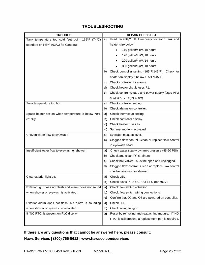
TROUBLESHOOTING
TROUBLE REPAIR CHECKLIST Tank temperature too cold (set point 165°F (74ºC)
standard or 145ºF (63ºC) for Canada):
a) Used recently? Full recovery for each tank and
heater size below:
• 119 gallon/4kW, 10 hours
• 120 gallon/4kW, 10 hours
• 200 gallon/4kW, 14 hours
• 330 gallon/6kW, 18 hours
b) Check controller setting (165°F/145ºF). Check for
heater on display if below 165°F/145ºF.
c) Check controller for alarms.
d) Check heater circuit fuses F1.
e) Check control voltage and power supply fuses PFU
& CFU & SFU (for 600V)
Tank temperature too hot: a) Check controller setting.
b) Check alarms on controller.
Space heater not on when temperature is below 70°F
(21°C): a) Check thermostat setting.
b) Check controller display.
c) Check heater fuses F2.
d) Summer mode is activated.
Uneven water flow to eyewash: a) Eyewash must be level.
b) Clogged flow control. Clean or replace flow control
in eyewash head.
Insufficient water flow to eyewash or shower: a) Check water supply dynamic pressure (45-90 PSI).
b) Check and clean “Y” strainers.
c) Check ball valves. Must be open and unclogged.
d) Clogged flow control. Clean or replace flow control
in either eyewash or shower.
Clear exterior light off: a) Check LED.
b) Check fuses PFU & CFU & SFU (for 600V)
Exterior light does not flash and alarm does not sound
when shower or eyewash is activated:
a) Check flow switch actuation.
b) Check flow switch wiring connections.
c) Confirm that Q2 and Q3 are powered on controller.
Exterior alarm does not flash, but alarm is sounding
when shower or eyewash is activated:
a) Check LED.
b) Check wiring to light.
If “NO RTC” is present on PLC display: a) Reset by removing and reattaching module. If “NO
RTC” is still present, a replacement part is required.
If there are any questions that cannot be answered here, please consult: Haws Services | (800) 766-5612 | www.hawsco.com/services

HAWS® P/N 0510000453 Rev.5 10/19 Model 8710 Page 26 of 32
SPARE PARTS
Please call Haws Services to order spare parts: 1-800-766-5612
FUSES PRIMARY (PFU), CONTROL (CFU) & SECONDARY (SFU)
VOLTAGE PFU CFU SFU (600V ONLY) QTY P/N TYPE QTY P/N TYPE QTY P/N TYPE
208V, 1PH 2 0210000298 FNQ-R-3
1 0210000646 LP-CC-2 - - - 208V, 3PH 2 0210000298 FNQ-R-3 240V,1PH 2 0210000298 FNQ-R-3 240V, 3PH 2 0210000298 FNQ-R-3 480V, 3PH 2 0210000070 FNQ-R-2 600V, 3PH 2 0210000756 FNQ-R-4/10 1 0210000758 FNQ-R-8/10
FUSES TANK HEATER (F1)
VOLTAGE 4KW TANK HEATER 6KW TANK HEATER
F1 F1 QTY P/N TYPE QTY P/N TYPE
208V, 1PH 2 0210000072 KTK-R-25 2 0210000292 JKS-40 208V, 3PH 3 0210000065 KTK-R-15 3 0210000072 KTK-R-25 240V, 1PH 2 0210000072 KTK-R-25 2 0210000293 JKS-35 240V, 3PH 3 0210000065 KTK-R-15 3 0210000164 KTK-R-20 480V, 3PH 3 0210000143 KTK-R-10 3 0210000143 KTK-R-10 600V, 3PH 3 0210000142 KTK-R-6 3 0210000143 KTK-R-10
FUSES SPACE HEATER (F2)
VOLTAGE 2.5KW SPACE HEATER
F2 QTY P/N TYPE
208V, 1PH 2 0210000164 KTK-R-20 208V, 3PH 3 0210000143 KTK-R-10 240V, 1PH 2 0210000065 KTK-R-15 240V, 3PH 3 0210000143 KTK-R-10 480V, 3PH 3 0210000142 KTK-R-6 600V, 3PH 3 0210000142 KTK-R-6
HAWS® P/N 0510000453 Rev.5 10/19 Model 8710 Page 27 of 32
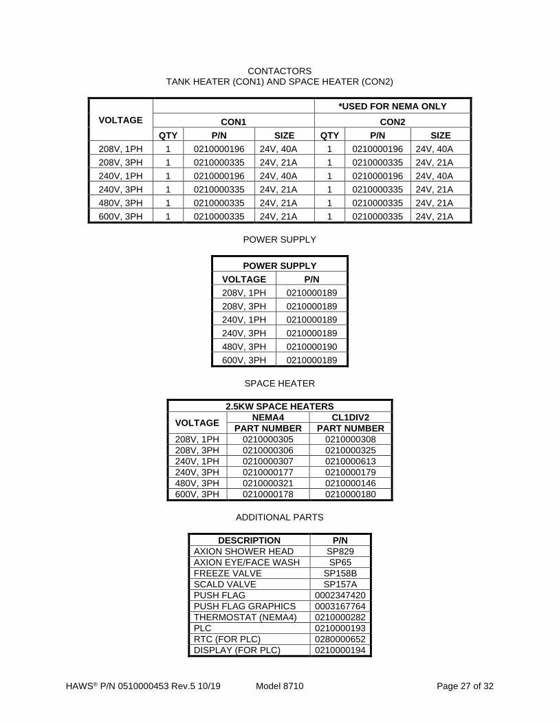
CONTACTORS TANK HEATER (CON1) AND SPACE HEATER (CON2)
VOLTAGE *USED FOR NEMA ONLY
CON1 CON2 QTY P/N SIZE QTY P/N SIZE
208V, 1PH 1 0210000196 24V, 40A 1 0210000196 24V, 40A 208V, 3PH 1 0210000335 24V, 21A 1 0210000335 24V, 21A 240V, 1PH 1 0210000196 24V, 40A 1 0210000196 24V, 40A 240V, 3PH 1 0210000335 24V, 21A 1 0210000335 24V, 21A 480V, 3PH 1 0210000335 24V, 21A 1 0210000335 24V, 21A 600V, 3PH 1 0210000335 24V, 21A 1 0210000335 24V, 21A
POWER SUPPLY
POWER SUPPLY VOLTAGE P/N 208V, 1PH 0210000189 208V, 3PH 0210000189 240V, 1PH 0210000189 240V, 3PH 0210000189 480V, 3PH 0210000190 600V, 3PH 0210000189
SPACE HEATER
2.5KW SPACE HEATERS
VOLTAGE NEMA4 CL1DIV2 PART NUMBER PART NUMBER
208V, 1PH 0210000305 0210000308 208V, 3PH 0210000306 0210000325 240V, 1PH 0210000307 0210000613 240V, 3PH 0210000177 0210000179 480V, 3PH 0210000321 0210000146 600V, 3PH 0210000178 0210000180
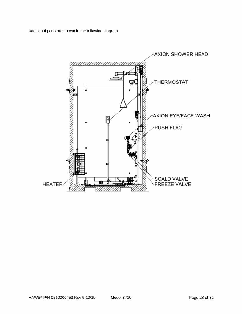
ADDITIONAL PARTS
DESCRIPTION P/N
AXION SHOWER HEAD SP829 AXION EYE/FACE WASH SP65 FREEZE VALVE SP158B SCALD VALVE SP157A PUSH FLAG 0002347420 PUSH FLAG GRAPHICS 0003167764 THERMOSTAT (NEMA4) 0210000282 PLC 0210000193 RTC (FOR PLC) 0280000652 DISPLAY (FOR PLC) 0210000194
HAWS® P/N 0510000453 Rev.5 10/19 Model 8710 Page 28 of 32
Additional parts are shown in the following diagram.
HAWS® P/N 0510000453 Rev.5 10/19 Model 8710 Page 29 of 32
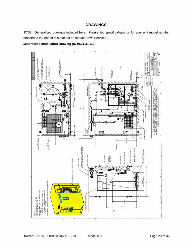
DRAWINGS NOTE: Generalized drawings included here. Please find specific drawings for your unit model number
attached to the end of this manual or contact Haws Services.
Generalized Installation Drawing (8710.21.31-GA)
HAWS® P/N 0510000453 Rev.5 10/19 Model 8710 Page 30 of 32
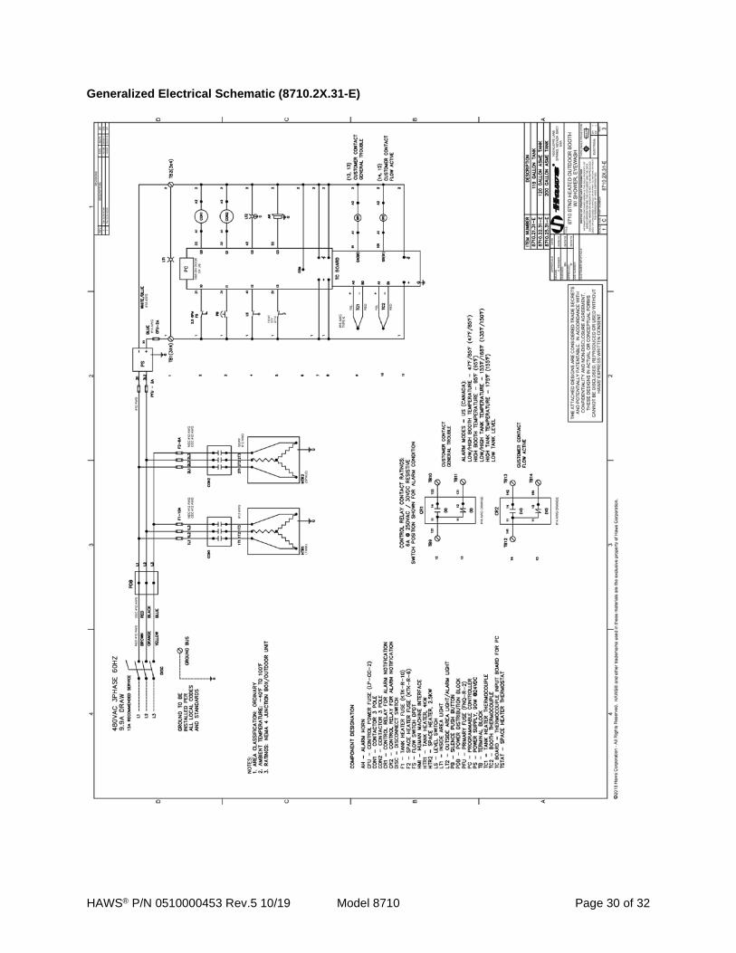
Generalized Electrical Schematic (8710.2X.31-E)

HAWS® P/N 0510000453 Rev.5 10/19 Model 8710 Page 31 of 32
Generalized Piping and Instrumentation Diagram (8710.21.31 & 8760.21.31 P&ID)

HAWS® P/N 0510000453 Rev.5 10/19 Model 8710 Page 32 of 32
LIMITED WARRANTY
HAWS warrants that this specific product is guaranteed against defective material or poor workmanship for a period of one year from date of shipment. HAWS liability under this warranty shall be discharged by furnishing without charge F.O.B. HAWS Factory any goods, or part thereof, which shall appear to the Company upon inspection to be of defective material or not of first class workmanship, provided that claim is made in writing to Haws within a reasonable period after receipt of the product. Where claims for defects are made, the defective part or parts shall be delivered to the Company, prepaid, for inspection. HAWS will not be liable for the cost of repairs, alterations or replacements, or for any expense connected therewith made by the owner or his agents, except upon written authority from HAWS, Sparks, Nevada. HAWS will not be liable for any damages caused by defective materials or poor workmanship, except for replacements, as provided above. Buyer agrees that Haws has made no other warranties either expressed or implied in addition to those above stated, except that of title with respect to any of the products or equipment sold hereunder and that HAWS shall not be liable for general, special, or consequential damages claimed to arise under the contract of sale. The emergency equipment manufactured by HAWS is warranted to function if installation and maintenance instructions provided are adhered to. The units also must be used for the purpose for which they were intended. This product is intended to supplement first-aid treatment. Due to widely varying conditions, Haws cannot guarantee that the use of this emergency equipment will prevent serious injury or the aggravation of existing or prior injuries.
NO OTHER WARRANTIES EXPRESSED OR IMPLIED ARE AUTHORIZED, PROVIDED OR GIVEN BY HAWS.
SHOULD YOU EXPERIENCE DIFFICULTY WITH THE INSTALLATION OF THIS MODEL PLEASE CALL: HAWS SERVICES: 1-800-766-5612
FOR CUSTOMER SERVICE: 1-888-640-4297
For more information on Haws products, see our website: www.hawsco.com
© 2018 Haws® Corporation – All Rights Reserved
HAWS® and other trademarks used in these materials are the exclusive property of Haws Corporation.