mobile servicing system to interface control document
TRANSCRIPT

SSP 42004, Part 2, Revision A
National Aeronautics and Space AdministrationInternational Space Station ProgramJohnson Space CenterHouston, Texas
International Space StationProgram
Mobile Servicing System to User (Generic)Interface Control DocumentPart 2
Revision A,
May 22, 1997
Type 1Approved by NASA

SSP 42004, Part 2 MSS to User ICDMay 22, 1997
REVISION AND HISTORY PAGE
REV. DESCRIPTION PUB.DATE
CHANGE 00–00

SSP 42004, Part 2 MSS to User ICDMay 22, 1997
PREFACE
SSP 42004, Mobile Servicing System to User (Generic) Interface Control Document,Part 2, shall be implemented on all new Program contractural and internal activity andshall be included in any existing contracts through contract changes. This document isunder the control of the Space Station Control Board (SSCB) with the concurrence of therespective International Partners, any changes or revisions will be approved by the SSCBand the respective International Partners.
Program Manager, DateInternational Space Station Alpha
SSP 42004, Part 2 MSS to User ICDMay 22, 1997
i
NASA/CSA
INTERNATIONAL SPACE STATION PROGRAM
MOBILE SERVICING SYSTEM TO USER (GENERIC)INTERFACE CONTROL DOCUMENT PART 2
DATE
Print Name
For NASA
DATE
Print Name
For CSA

SSP 42004, Part 2 MSS to User ICDMay 22, 1997
ii
INTERNATIONAL SPACE STATION PROGRAM
MOBILE SERVICING SYSTEM TO USER (GENERIC)INTERFACE CONTROL DOCUMENT PART 2
CONCURRENCE
PREPARED BY:
CHECKED BY:
SIGNATURE
SUPERVISED BY (NASA):
PRINT NAME ORGN
DATE
SIGNATURE
PRINT NAME ORGN
DATE
SUPERVISED BY (BOEING):
SIGNATURE
PRINT NAME ORGN
DATE
SIGNATURE
PRINT NAME ORGN
DATE
DQA:
SIGNATURE
PRINT NAME ORGN
DATE
SSP 42004, Part 2 MSS to User ICDMay 22, 1997
vi
CONCURRENCE
INTERNATIONAL SPACE STATION PROGRAM
MOBILE SERVICING SYSTEM TO USER (GENERIC)INTERFACE CONTROL DOCUMENT PART 2
Product Group–1 ICWG
Product Group–3 ICWG
SIGNATURE
PRINT NAME
DATE
SIGNATURE
PRINT NAME
DATE
Representative for Concurrence
Representative for Concurrence
SPAR
SIGNATURE
PRINT NAME
DATE
Product Group–2 ICWG
SIGNATURE
PRINT NAME
DATE
Representative for Concurrence
Representative for Concurrence

SSP 42004, Part 2 MSS to User ICDMay 22, 1997
vii
INTERNATIONAL SPACE STATION PROGRAM
MOBILE SERVICING SYSTEM TO USER (GENERIC)INTERFACE CONTROL DOCUMENT PART 2
LIST OF CHANGES
MAY 22, 1997
All changes to paragraphs, tables, and figures in this document are shown below:
SSCBD ENTRY DATE CHANGE PARAGRAPH(S)
TABLE(S)
FIGURE(S)
APPENDIX(ES)
ADDENDA

SSP 42004, Part 2 MSS to User ICDMay 22, 1997
1
TABLE OF CONTENTS
PARAGRAPH PAGE
1.0 INTRODUCTION 1 - 1. . . . . . . . . . . . . . . . . . . . . . . . . . . . . . . . . . . . . . . . . . . . . . . . . . .
1.1 PURPOSE AND SCOPE 1 - 1. . . . . . . . . . . . . . . . . . . . . . . . . . . . . . . . . . . . . . . . . . . .
1.2 PRECEDENCE 1 - 1. . . . . . . . . . . . . . . . . . . . . . . . . . . . . . . . . . . . . . . . . . . . . . . . . . . .
1.3 RESPONSIBILITY AND CHANGE 1 - 1. . . . . . . . . . . . . . . . . . . . . . . . . . . . . . . . . . . .
2.0 APPLICABLE DOCUMENTS 2 - 1. . . . . . . . . . . . . . . . . . . . . . . . . . . . . . . . . . . . . . . . .
SECTION A3 PDGF TO USER INTERFACES A3 – 1. . . . . . . . . . . . . . . . . . . . . . . . . . . . . . . . . . . . . .
A3 INTERFACE DEFINITION A3 – 1. . . . . . . . . . . . . . . . . . . . . . . . . . . . . . . . . . . . . . . . . . .
A3.1 GENERAL A3 – 1. . . . . . . . . . . . . . . . . . . . . . . . . . . . . . . . . . . . . . . . . . . . . . . . . . . . . . . . .
A3.1.1 INTERFACE DESCRIPTION A3 – 1. . . . . . . . . . . . . . . . . . . . . . . . . . . . . . . . . . . . . . . . .
A3.1.2 ENGINEERING UNITS AND TOLERANCES A3 – 1. . . . . . . . . . . . . . . . . . . . . . . . . . .
A3.2 STRUCTURAL/MECHANICAL INTERFACES A3 – 1. . . . . . . . . . . . . . . . . . . . . . . . . .
A3.3 ENVIRONMENTS A3 – 1. . . . . . . . . . . . . . . . . . . . . . . . . . . . . . . . . . . . . . . . . . . . . . . . . .
A3.4 ELECTRICAL INTERFACES A3 – 1. . . . . . . . . . . . . . . . . . . . . . . . . . . . . . . . . . . . . . . . .
A3.4.1 POWER, RETURN AND GROUNDING INTERFACES A3 – 2. . . . . . . . . . . . . . . . . .
A3.4.2 PDGF POWER CONNECTORS AND PIN ASSIGNMENTS A3 – 2. . . . . . . . . . . . . .
A3.4.3 PDGF DATA AND PFM VIDEO INTERFACES A3 – 2. . . . . . . . . . . . . . . . . . . . . . . . . .
A3.4.3.1 PDGF DATA AND VIDEO CONNECTORS AND PIN ASSIGNMENTS A3 – 3. . . . .
A3.4.4 VIDEO PROVISIONS FOR USERS A3 – 3. . . . . . . . . . . . . . . . . . . . . . . . . . . . . . . . . . .
A3.5 THERMAL INTERFACES A3 – 3. . . . . . . . . . . . . . . . . . . . . . . . . . . . . . . . . . . . . . . . . . . .
A3.6 SOFTWARE INTERFACES A3 – 3. . . . . . . . . . . . . . . . . . . . . . . . . . . . . . . . . . . . . . . . . .
A3.7 PDGF TARGET A3 – 3. . . . . . . . . . . . . . . . . . . . . . . . . . . . . . . . . . . . . . . . . . . . . . . . . . . .
SECTION B3 MCAS TO USER INTERFACE B3 – 1. . . . . . . . . . . . . . . . . . . . . . . . . . . . . . . . . . . . . . .
B3 INTERFACE DEFINITION B3 – 1. . . . . . . . . . . . . . . . . . . . . . . . . . . . . . . . . . . . . . . . . . .
B3.1 GENERAL B3 – 1. . . . . . . . . . . . . . . . . . . . . . . . . . . . . . . . . . . . . . . . . . . . . . . . . . . . . . . . .
B3.1.1 INTERFACE DESCRIPTION B3 – 1. . . . . . . . . . . . . . . . . . . . . . . . . . . . . . . . . . . . . . . . .
B3.1.2 DELETED B3 – 1. . . . . . . . . . . . . . . . . . . . . . . . . . . . . . . . . . . . . . . . . . . . . . . . . . . . . . . . .
B3.1.3 ENGINEERING UNITS AND TOLERANCES B3 – 1. . . . . . . . . . . . . . . . . . . . . . . . . . .
B3.2 STRUCTURAL/MECHANICAL INTERFACES B3 – 1. . . . . . . . . . . . . . . . . . . . . . . . . .
B3.3 DELETED B3 – 2. . . . . . . . . . . . . . . . . . . . . . . . . . . . . . . . . . . . . . . . . . . . . . . . . . . . . . . . .
B3.4 ELECTRICAL INTERFACES B3 – 2. . . . . . . . . . . . . . . . . . . . . . . . . . . . . . . . . . . . . . . . .
B3.4.1 POWER, RETURN AND GROUNDING INTERFACES B3 – 2. . . . . . . . . . . . . . . . . .
B3.4.2 POWER CONNECTORS AND PIN ASSIGNMENTS B3 – 2. . . . . . . . . . . . . . . . . . . .
B3.4.3 DATA INTERFACES B3 – 2. . . . . . . . . . . . . . . . . . . . . . . . . . . . . . . . . . . . . . . . . . . . . . . .
B3.4.3.1 DATA CONNECTORS AND PIN ASSIGNMENTS B3 – 2. . . . . . . . . . . . . . . . . . . . . . .
B3.5 ENVIRONMENTS B3 – 2. . . . . . . . . . . . . . . . . . . . . . . . . . . . . . . . . . . . . . . . . . . . . . . . . .
B3.6 SOFTWARE INTERFACES B3 – 2. . . . . . . . . . . . . . . . . . . . . . . . . . . . . . . . . . . . . . . . . .
SECTION C3 RESERVED C3 – 1. . . . . . . . . . . . . . . . . . . . . . . . . . . . . . . . . . . . . . . . . . . . . . . . . . . . . . .
SECTION D3 RESERVED D3 – 1. . . . . . . . . . . . . . . . . . . . . . . . . . . . . . . . . . . . . . . . . . . . . . . . . . . . . . .

SSP 42004, Part 2 MSS to User ICDMay 22, 1997
2
SECTION E3 RESERVED E3 – 1. . . . . . . . . . . . . . . . . . . . . . . . . . . . . . . . . . . . . . . . . . . . . . . . . . . . . . .
SECTION F3 RESERVED F3 – 1. . . . . . . . . . . . . . . . . . . . . . . . . . . . . . . . . . . . . . . . . . . . . . . . . . . . . . .
SECTION G3 RESERVED G3 – 1. . . . . . . . . . . . . . . . . . . . . . . . . . . . . . . . . . . . . . . . . . . . . . . . . . . . . . .
SECTION H3 RESERVED H3 – 1. . . . . . . . . . . . . . . . . . . . . . . . . . . . . . . . . . . . . . . . . . . . . . . . . . . . . . .
SECTION I3 FRGF TO USER INTERFACES I3 – 1. . . . . . . . . . . . . . . . . . . . . . . . . . . . . . . . . . . . . .
I3 INTERFACE DEFINITION I3 – 1. . . . . . . . . . . . . . . . . . . . . . . . . . . . . . . . . . . . . . . . . . .
APPENDIX
APPENDIX A: ABBREVIATIONS AND ACRONYMS A – 1. . . . . . . . . . . . . . . . . . . . . . . . . . . . . . . . .
APPENDIX B: TBD LIST B – 1. . . . . . . . . . . . . . . . . . . . . . . . . . . . . . . . . . . . . . . . . . . . . . . . . . . . . . . . .
FIGURES
A3.2–1 PDGF INTERFACE TO USERS A3 –4. . . . . . . . . . . . . . . . . . . . . . . . . . . . . . . . . . . . . .
A3.2–2 PDGF INTERFACE TO USERS A3 – 5. . . . . . . . . . . . . . . . . . . . . . . . . . . . . . . . . . . . . .
A3.2–3 PDGF INTERFACE TO USERS A3 – 6. . . . . . . . . . . . . . . . . . . . . . . . . . . . . . . . . . . . . .
A3.4–1 PDGF TO USER (VIA SSRMS) ELECTRICAL INTERFACE AND CURRENT PROTECTIONDIAGRAM A3 – 7. . . . . . . . . . . . . . . . . . . . . . . . . . . . . . . . . . . . . . . . . . . . . . . . . . . . . . . . .
A3.4–2 PDGF TO USER (VIA POA) ELECTRICAL INTERFACE AND CURRENT PROTECTIONDIAGRAM A3 – 8. . . . . . . . . . . . . . . . . . . . . . . . . . . . . . . . . . . . . . . . . . . . . . . . . . . . . . . . .
A3.4–3 PDGF TO USER (VIA SPDM) ELECTRICAL INTERFACE AND CURRENT PROTECTIONDIAGRAM A3 – 9. . . . . . . . . . . . . . . . . . . . . . . . . . . . . . . . . . . . . . . . . . . . . . . . . . . . . . . . .
A3.4–4 JEM–PM TO PDGF KEEP–ALIVE ELECTRICAL SYSTEM DIAGRAM A3 – 10. . . . .
A3.4–5 APM TO PDGF KEEP–ALIVE ELECTRICAL SYSTEM DIAGRAM A3 – 11. . . . . . . . .
B3.2–1 MCAS TO USER MECHANICAL INTERFACE B3– 3. . . . . . . . . . . . . . . . . . . . . . . . . .
B3.2–2 MCAS TO USER MECHANICAL INTERFACE B3 – 4. . . . . . . . . . . . . . . . . . . . . . . . . .
B3.2–3 MCAS TO USER MECHANICAL INTERFACE 3B – 5. . . . . . . . . . . . . . . . . . . . . . . . . .
B3.4–1 MCAS TO USER ELECTRICAL INTERFACE AND CURRENT PROTECTION DIAGRAM . . . . . . . . B3– 8
TABLES
A3.4.2–1 PDGF POWER FROM SSRMS (PRIME) CHARACTERISTICS, CONNECTORS, AND PINASSIGNMENTS (J7) A3 – 12. . . . . . . . . . . . . . . . . . . . . . . . . . . . . . . . . . . . . . . . . . . . . . . .
A3.4.2–2 PDGF POWER FROM SSRMS (REDUNDANT) CHARACTERISTICS, CONNECTORS, AND PINASSIGNMENTS (J8) A3 – 13. . . . . . . . . . . . . . . . . . . . . . . . . . . . . . . . . . . . . . . . . . . . . . . .
A3.4.2–3 PDGF POWER FROM POA (PRIME) CHARACTERISTICS, CONNECTORS, AND PINASSIGNMENTS (J7) A3 – 14. . . . . . . . . . . . . . . . . . . . . . . . . . . . . . . . . . . . . . . . . . . . . . . .
A3.4.2–4 PDGF POWER FROM POA (REDUNDANT) CHARACTERISTICS, CONNECTORS, AND PINASSIGNMENTS (J8) A3 – 15. . . . . . . . . . . . . . . . . . . . . . . . . . . . . . . . . . . . . . . . . . . . . . . .
A3.4.3.1–1 PDGF DATA AND VIDEO FROM SSRMS (PRIME) CONNECTORS AND PIN ASSIGNMENTS (J5)A3 – 16
A3.4.3.1–2 PDGF DATA AND VIDEO FROM SSRMS (REDUNDANT) CONNECTORS AND PINASSIGNMENTS (J6) A3 – 17. . . . . . . . . . . . . . . . . . . . . . . . . . . . . . . . . . . . . . . . . . . . . . . .
A3.4.3.1–3 PDGF DATA AND VIDEO FROM POA (PRIME) CONNECTORS AND PIN ASSIGNMENTS (J5) . . A3 – 18
A3.4.3.1–4 PDGF DATA AND VIDEO FROM POA (REDUNDANT) CONNECTORS AND PIN ASSIGNMENTS(J6) A3 – 19. . . . . . . . . . . . . . . . . . . . . . . . . . . . . . . . . . . . . . . . . . . . . . . . . . . . . . . . . . . . . . .

SSP 42004, Part 2 MSS to User ICDMay 22, 1997
3
A3.4.4–1 VIDEO PROVISIONS FOR USERS A3 – 20. . . . . . . . . . . . . . . . . . . . . . . . . . . . . . . . . . .
A3.4.4–2 DELETED A3 – 21. . . . . . . . . . . . . . . . . . . . . . . . . . . . . . . . . . . . . . . . . . . . . . . . . . . . . . . . .
B3.4.2–1 MCAS TO USER PRIME AND REDUNDANT POWER AND DATA CHARACTERISTICS,CONNECTORS, AND PIN ASSIGNMENTS B3– 9. . . . . . . . . . . . . . . . . . . . . . . . . . . .

SSP 42004, Part 2 MSS to User ICDMay 22, 1997
1 - 1
1.0 INTRODUCTION
1.1 PURPOSE AND SCOPE
This Interface Control Document (ICD) Part 2 defines and controls the physical and functionalinterfaces between the Canadian Mobile Servicing System (MSS) and Users. For purposes ofthis ICD, the term “user” shall be defined as any payload, pallet, or Orbit–Replaceable Unit(ORU) that interfaces with the Space Station Remote Manipulator System (SSRMS) LatchingEnd Effector (LEE), the Special Purpose Dexterous Manipulator (SPDM) LEE, thePayload/ORU Accommodation (POA), the Mobile Base System (MBS) Common Attach System(CAS), or the SPDM manipulators.
1.2 PRECEDENCE
In the event of conflict between SSP 41000, Space Station System Specification, and thecontents of this ICD, the requirements of SSP 41000 shall take precedence.
1.3 RESPONSIBILITY AND CHANGE
This document is prepared and maintained in accordance with SSP 30459, International SpaceStation Interface Control Plan. The National Aeronautics and Space Administration (NASA)shall delegate the responsibility for preparation and maintenance of this ICD Part 2.

SSP 42004, Part 2 MSS to User ICDMay 22, 1997
2 - 1
2.0 APPLICABLE DOCUMENTS
The following documents of the date and issue shown include specifications, models, standards,and form a part of this document to the extent specified herein.
DOCUMENT NO. TITLE
SSP 30482 Electrical Power Specification and Standards:Rev A, CN–001 Vol I, Electrical Performance Specifications1 Jan 1994
SSP 30482 Electrical Power Specification and Standards:Rev A, CN–001 Vol II, Consumer Constraints1 Jan 1994
SSP 41000 System Specification for Space StationRev E28 Jan 1997
SSQ 21635 Electrical Connector Specifications
NSTS–21000–IDD–ISS Shuttle Orbiter/International Space Station InterfaceDefinition Document
SSP 30459 International Space Station Interface Control Plan
SSP 42003, Part 2 Space Station Manned Base to Mobile Servicing SystemInterface Control Document, Part 2
SSP 42004, Part 1 Mobile Servicing System (MSS) to User (Generic)Interface Control Document, Part 1

SSP 42004, Part 2 MSS to User ICDMay 22, 1997
A3 – 1
SECTION A3 PDGF TO USER INTERFACES
A3 INTERFACE DEFINITION
A3.1 GENERAL
A3.1.1 INTERFACE DESCRIPTION
The physical interface (mechanical, structural, thermal and environmental) plane is defined atthe Power and Data Grapple Fixture (PDGF) mounting ring surface to the User. The utilityinterface plane (power, data and video) is defined between the PDGF harness and the Userconnectors at the User end of the harness.
A3.1.2 ENGINEERING UNITS AND TOLERANCES
Unless otherwise noted herein, all dimensions are shown in the English system of inch pound(IP) units.
A3.2 STRUCTURAL/MECHANICAL INTERFACES
The PDGF attaches to the User via eight fasteners. The bolt hole pattern and related mechanicalinstallation details are defined in Figures A3.2–1 through A3.2–3.
A3.3 ENVIRONMENTS
The PDGF to User electromagnetic, grounding and bonding interface implementation will be asdefined in Figures A3.2–1 through A3.2–3.
A3.4 ELECTRICAL INTERFACES
The SSRMS Tip LEE will provide power, data and Pulse Frequency Modulation (PFM) syncand control, and PFM video interfaces to the User via the User PDGF as defined in FigureA3.4–1.

SSP 42004, Part 2 MSS to User ICDMay 22, 1997
A3 – 2
The MBS POA will provide power, data and PFM sync and control, and PFM video interfacesto the User via the User PDGF as defined in Figure A3.4–2.
The SPDM LEE will provide power interfaces to the User via the User PDGF as defined inFigure A3.4–3 (TBD#1).
The SSRMS will provide Keep–Alive power to the JEM–PM via the PDGF as defined in FigureA3.4–4.
The SSRMS will provide Keep–Alive power to the APM via the PDGF as defined in FigureA3.4–5.
A3.4.1 POWER, RETURN AND GROUNDING INTERFACES
The SSRMS LEE and MBS POA will provide power, return and grounding interfaces to theUser via the PDGF as shown in Figures A3.4–1 and A3.4–2.
The PDGF external harness design for a User will be unique for each application. An exampleof a PDGF external harness design is shown in SSP 42003, Part 2, Section D.
A3.4.2 PDGF POWER CONNECTORS AND PIN ASSIGNMENTS
The PDGF power connectors and pin assignments for the User (power via the SSRMS Tip LEE)will be as defined in Tables A3.4.2.–1 through A3.4.2.–2.
The PDGF power connectors and pin assignments for the User ( power via the MBS POA) willbe as defined in Tables A3.4.2.–3 through A3.4.2.–4.
The PDGF power connectors and pin assignments for the User ( power via the SPDM LEE) willbe as defined in Tables A3.4.2.–5 through A3.4.2.–6 (TBD#2).
A3.4.3 PDGF DATA AND PFM VIDEO INTERFACES
The C & DH subsystem will support data interfaces between the User and the SSRMS LEE.
The C & DH subsystem will support data interfaces between the User and the MBS POA.
PFM sync and control and PFM video will be carried by copper lines between the User PDGFand the SSRMS LEE, and User PDGF and the MBS POA.

SSP 42004, Part 2 MSS to User ICDMay 22, 1997
A3 – 3
A3.4.3.1 PDGF DATA AND VIDEO CONNECTORS AND PIN ASSIGNMENTS
The PDGF data and PFM video connectors and pin assignments for the User (via the SSRMSTip LEE) will be as defined in Tables A3.4.3.1–1 through A3.4.3.1–2.
The PDGF data and PFM video connectors and pin assignments for the User ( via the MBSPOA) will be as defined in Tables A3.4.3.1–3 through A3.4.3.1–4.
A3.4.4 VIDEO PROVISIONS FOR USERS
During SSRMS or MBS POA operations, the MSS will provide video capability as defined inTable A3.4.4–1.
A3.5 THERMAL INTERFACES
The PDGF to User thermal interface implementation will be as defined in Figures A3.2–1through A3.2–3.
A3.6 SOFTWARE INTERFACES
There are no software interfaces between the User PDGF and the SSRMS LEE or MBS POA.
A3.7 PDGF TARGET
The PDGF grapple target will have features as defined in Figures A3.2–1 through A3.2–3.

SSP 42004, Part 2 MSS to User ICDMay 22, 1997
A3 –4
(Reference SPAR drawing 51618–0012, sheet 1 of 3)
FIGURE A3.2–1 PDGF INTERFACE TO USERS

SSP 42004, Part 2 MSS to User ICDMay 22, 1997
A3 – 5
(Reference SPAR drawing 51618–0012, sheet 2 of 3)
FIGURE A3.2–2 PDGF INTERFACE TO USERS

SSP 42004, Part 2 MSS to User ICDMay 22, 1997
A3 – 6
(Reference SPAR drawing 51618–0012, sheet 3 of 3)
FIGURE A3.2–3 PDGF INTERFACE TO USERS

SSP 42004, Part 2 MSS to User ICDMay 22, 1997
A3 – 7
User ProvidedConnectors
É
12ga
PDGF/User Interface Plane Provided Connectors
SSRMS LEE/User PDGFInterface Plane
Payload Power A1Return A1
SSBA
12gaPayload Power A2
Return A2
Ground
ÉÉÉÉÉÉÉÉÉÉÉÉ
J1
ÉÉÉÉÉÉÉÉÉÉÉÉÉÉ
ÉÉÉÉÉÉÉÉÉÉÉÉ
ÉÉÉÉÉÉÉÉÉÉÉÉ
ÉÉÉÉÉÉÉÉÉÉÉÉ
ÉÉÉÉÉÉÉÉÉÉÉÉ
Internal PDGFWiring andConnectors
User Determined
PDGF Harness LengthÉÉÉÉÉÉÉÉÉÉÉÉÉÉ
SSRMS
ÉÉÉÉÉÉÉÉÉÉÉÉÉÉ
User Bus A
Data Bus A
J3
J5
J7
J5
J7
12gaPayload Power B1Return B1
12ga
Payload Power B2Return B2
Ground
ÉÉÉÉÉÉÉÉÉÉÉÉ
1 TSP 22ga
J2
ÉÉÉÉÉÉÉÉÉÉÉÉ
ÉÉÉÉÉÉÉÉÉÉÉÉ
ÉÉÉÉÉÉÉÉÉÉÉÉ
ÉÉÉÉÉÉÉÉÉÉÉÉ
ÉÉÉÉÉÉÉÉÉÉÉÉ
ÉÉÉÉÉÉÉÉÉÉÉÉÉÉÉÉÉÉÉÉÉÉÉÉ
User Bus B
Data Bus B
J4
J6
J8
J6
J8
MSS Local Bus B (LB1 B)
1 TSP 22ga
MSS Local Bus A (LB1 A)
1 TSP
Bus Coupler
RPC25A
Return
Return
RPC25A
12ga
12ga
To UserLoads
To UserLoads
PFM Video 1PFM Video 2 RD316
PFM Sync and Control 1 RD316
PFM Video 3
PFM Sync and Control 2 RD316
RD316RD316RD316
RD316
RD316
12ga12ga
12ga12ga
12ga
12ga
12ga
12ga12ga
12ga12ga
12ga
1 TSP 22ga
1 TSP 22ga
RD316RD316RD316
RD316
RD316
12ga12ga
12ga12ga
12ga
12ga12ga
12ga12ga
12ga
1 TSP 22gaSSBA
SSBASSBA
PDGF User Interface Plane
RD316
RD316
FIGURE A3.4–1 PDGF TO USER (VIA SSRMS) ELECTRICAL INTERFACE AND CURRENTPROTECTION DIAGRAM

SSP 42004, Part 2 MSS to User ICDMay 22, 1997
A3 – 8
MBS
12ga
POA/User PDGFInterface Plane
Payload Power A1Return A1
SSBA
12gaPayload Power A2Return A2
Ground
ÏÏÏÏÏÏÏ
J1
ÏÏÏÏÏÏ
ÏÏÏÏÏÏÏÏÏÏÏÏÏÏ
ÏÏÏÏÏÏÏ
ÏÏÏÏÏÏÏÏÏÏÏÏ
ÏÏÏÏÏÏ
Internal PDGFWiring andConnectors
ÏÏÏÏÏÏ
POA
ÏÏÏÏÏÏÏ
User Bus A
Data Bus A
J3
J5
J7
J5
J7
12gaPayload Power B1
Return B1
12gaPayload Power B2
Return B2
Ground
ÏÏÏÏÏÏ
1 TSP 22ga
J2
ÏÏÏÏÏÏ
ÏÏÏÏÏÏÏÏÏÏÏÏ
ÏÏÏÏÏÏ
ÏÏÏÏÏÏÏÏÏÏÏÏÏÏ
ÏÏÏÏÏÏÏ
ÏÏÏÏÏÏÏÏÏÏÏÏÏÏ
User Bus B
Data Bus B
J4
J6
J8
J6
J8
SSBAMSS Local Bus B (LB1 B)
1 TSP 22ga
MSS Local Bus A (LB1 A)
1 TSP
RPC25A
Return
Return
RPC25A
12ga
12ga
To UserLoads
To UserLoads
PFM Video 1PFM Video 2 RD316PFM Sync and Control 1 RD316
PFM Video 3
PFM Sync and Control 2 RD316
RD316RD316RD316
RD316
RD316
12ga12ga
12ga12ga
12ga
12ga
12ga
12ga12ga
12ga12ga
12ga
1 TSP 22ga
1 TSP 22ga 1 TSP 22ga
1 TSP 22ga
RD316RD316RD316
RD316
RD316
12ga12ga
12ga12ga
12ga
12ga12ga
12ga12ga
12ga
1 TSP 22ga
User ProvidedConnectors
ÉÉÉÉ
PDGF/User Interface Plane Provided Connectors
Bus Coupler
User Determined
PDGF Harness Length
PDGF User Interface Plane
RD316
RD316
FIGURE A3.4–2 PDGF TO USER (VIA POA) ELECTRICAL INTERFACE AND CURRENTPROTECTION DIAGRAM

SSP 42004, Part 2 MSS to User ICDMay 22, 1997
A3 – 9
TBD #1
FIGURE A3.4–3 PDGF TO USER (VIA SPDM) ELECTRICAL INTERFACE AND CURRENTPROTECTION DIAGRAM

SSP 42004, Part 2 MSS to User ICDMay 22, 1997
A3 – 10
ÓÓÓÓÓÓÓÓ
ÓÓÓÓÓÓÓÓÓÓ
ÑÑÑÑÑÑÑ
ÓÓÓÓÓÓÓÓÓÓ
ÓÓÓÓÓÓÓÓÓÓ
ÑÑÑÑÑÑÑ
ÓÓÓÓÓÓÓÓÓÓ
ÑÑÑÑÑÑÑÑÑÑÑÑÑÑÑÑ
ÑÑÑÑÑÑÑÑÑÑÑÑÑÑÑÑ
2
2
1
2
2
1
12ga
12ga
12ga
12ga
12ga 2
To VSC J2
12ga
12ga
12ga
12ga
12ga
1
2
2
2
2
1
2
2
2
NASDAHarnesses and
Connectors
JEM to PDGFInterfacePlane
NASDAConnector
PanelPDGF Harnesses
andConnectors
JEMHeaters
JEMHeaters
ÓÓÓÓÓÓÓÓ
ÓÓÓÓÓÓÓÓ ÓÓ
ÓÓNASDA ConnectorsPDGF Connectors
ResourcesFromSSRMS
ÑÑÑÑÑÑÑÑÑÑÑÑÑÑÑÑÑÑÑÑÑÑÑÑÑÑÑÑÑÑÑÑÑÑÑÑÑÑÑÑÑÑÑÑÑ
JEM
PDGF
To VSC J2
8ga
8ga
8ga
8ga
8ga
8ga
To VSC J3
To VSC J3
J7
J8
Notes:1) VSC not shown.2) Total keep–alive power drawn will include VSC keep–alive power as defined in SSP 42003, Section H.
ResourcesFromSSRMS
FIGURE A3.4–4 JEM–PM TO PDGF KEEP–ALIVE ELECTRICAL SYSTEM DIAGRAM

SSP 42004, Part 2 MSS to User ICDMay 22, 1997
A3 – 11
ÓÓÓÓÓÓÓÓÓ
ÓÓÓÓÓÓÓÓÓÓ
ÑÑÑÑÑÑÑ
ÓÓÓÓÓÓÓÓÓÓ
ÓÓÓÓÓÓÓÓÓÓ
ÑÑÑÑÑÑÑ
ÓÓÓÓÓÓÓÓÓÓ
ÑÑÑÑÑÑÑÑÑÑÑÑÑÑÑÑÑÑÑÑ
ÑÑÑÑÑÑÑÑÑÑÑÑÑÑÑÑ
2
2
1
2
2
1
12ga
12ga
12ga
12ga
12ga 2
12ga
12ga
12ga
12ga
12ga
1
2
2
2
2
1
2
2
2
ESAHarnesses and
Connectors
APM to PDGF Interface PlaneESA Connector Panel
PDGF Harnessesand
Connectors
APMHeaters
APMHeaters
ÓÓÓÓÓÓÓÓ
ÓÓÓÓÓÓÓÓÓÓ ÓÓESA Connectors
PDGF Connectors
ResourcesFromSSRMS
ÑÑÑÑÑÑÑÑÑÑÑÑÑÑÑÑÑÑÑÑÑÑÑÑÑÑÑÑÑÑÑÑÑÑÑÑÑÑÑÑÑÑ
APM
PDGF
8ga
8ga
8ga
8ga
8ga
8ga
J7
J8
ÑÑÑÑÑÑÑÑÑÑÑÑÑÑÑÑÑÑÑÑÑÑÑÑÑÑÑÑÑÑÑÑÑ
ÓÓÓÓÓ
ÑÑÑÑÑÑÑÑÑÑÑÑ
ÓÓÓÓÓÓÓÓÓÓ
ÓÓÓÓÓÓ
ÓÓÓÓÓÓÓÓÓÓÓÓ
J5
J6
1 TSP
1 TSP
ÑÑÑÑÑÑÑÑÑÑÑÑÑÑÑÑ
ÑÑÑÑÑÑÑÑÑÑÑÑÑÑÑÑ
BC BC
Heater Control
Unit
Heater Control
UnitNote 1) The MSS LB termination isshown for reference only.
ResourcesFromSSRMS
FIGURE A3.4–5 APM TO PDGF KEEP–ALIVE ELECTRICAL SYSTEM DIAGRAM

SSP 42004, Part 2 MSS to User ICDMay 22, 1997
A3 – 12
TABLE A3.4.2–1 PDGF POWER FROM SSRMS (PRIME) CHARACTERISTICS,CONNECTORS, AND PIN ASSIGNMENTS (J7)
ÁÁÁÁÁÁÁÁÁÁÁÁÁÁÁÁÁÁÁÁÁÁÁÁÁÁÁÁÁÁÁÁÁÁÁÁÁÁÁÁÁÁÁÁÁÁÁÁÁÁÁÁÁÁÁÁÁÁÁÁÁÁÁÁ
POWER SPECIFICATIONSÁÁÁÁÁÁÁÁÁÁÁÁÁÁÁÁÁÁÁÁÁÁÁÁÁ
ContactID
ÁÁÁÁÁÁÁÁÁÁÁÁÁÁÁÁÁÁÁÁÁÁÁÁÁ
SignalFunction
ÁÁÁÁÁÁÁÁÁÁÁÁÁÁÁÁÁÁÁÁ
Peak 2
Power
(kW)
ÁÁÁÁÁÁÁÁÁÁÁÁÁÁÁÁÁÁÁÁÁÁÁÁÁ
MinimumVoltage
(VDC)
ÁÁÁÁÁÁÁÁÁÁÁÁÁÁÁÁÁÁÁÁÁÁÁÁÁ
MaximumCurrent 3
[A]
ÁÁÁÁÁÁÁÁÁÁÁÁÁÁÁÁÁÁÁÁ
EMCClass
ÁÁÁÁÁÁÁÁÁÁÁÁÁÁÁÁÁÁÁÁÁÁÁÁÁ
Power 1
Quality Type
ÁÁÁÁÁÁÁÁÁÁÁÁÁÁÁÁÁÁÁÁÁÁÁÁÁÁÁÁÁÁ
Wire Gauge
(ga)
ÁÁÁÁÁÁÁÁÁÁÁÁÁÁÁÁÁÁÁÁÁÁÁÁÁÁÁÁÁÁÁÁÁÁÁÁÁÁÁÁÁÁÁÁÁÁÁÁÁÁÁÁÁÁÁÁÁÁÁÁÁÁÁÁÁÁÁÁÁÁÁÁÁÁÁÁÁÁÁÁ
35
49
50
51
52
ÁÁÁÁÁÁÁÁÁÁÁÁÁÁÁÁÁÁÁÁÁÁÁÁÁÁÁÁÁÁÁÁÁÁÁÁÁÁÁÁÁÁÁÁÁÁÁÁÁÁÁÁÁÁÁÁÁÁÁÁÁÁÁÁÁÁÁÁÁÁÁÁÁÁÁÁÁÁÁÁ
Ground
PayloadPower Bus 1
Return 1
PayloadPower Bus 2
Return 2
ÁÁÁÁÁÁÁÁÁÁÁÁÁÁÁÁÁÁÁÁÁÁÁÁÁÁÁÁÁÁÁÁÁÁÁÁÁÁÁÁÁÁÁÁÁÁÁÁÁÁÁÁÁÁÁÁÁÁÁÁÁÁÁÁ
1.8
1.8
1.8
1.8
1.8
ÁÁÁÁÁÁÁÁÁÁÁÁÁÁÁÁÁÁÁÁÁÁÁÁÁÁÁÁÁÁÁÁÁÁÁÁÁÁÁÁÁÁÁÁÁÁÁÁÁÁÁÁÁÁÁÁÁÁÁÁÁÁÁÁÁÁÁÁÁÁÁÁÁÁÁÁÁÁÁÁ
0
108.5
108.5
108.5
108.5
ÁÁÁÁÁÁÁÁÁÁÁÁÁÁÁÁÁÁÁÁÁÁÁÁÁÁÁÁÁÁÁÁÁÁÁÁÁÁÁÁÁÁÁÁÁÁÁÁÁÁÁÁÁÁÁÁÁÁÁÁÁÁÁÁÁÁÁÁÁÁÁÁÁÁÁÁÁÁÁÁ
25
25
25
25
25
ÁÁÁÁÁÁÁÁÁÁÁÁÁÁÁÁÁÁÁÁÁÁÁÁÁÁÁÁÁÁÁÁÁÁÁÁÁÁÁÁÁÁÁÁÁÁÁÁÁÁÁÁÁÁÁÁÁÁÁÁÁÁÁÁ
EO
EO
EO
EO
EO
ÁÁÁÁÁÁÁÁÁÁÁÁÁÁÁÁÁÁÁÁÁÁÁÁÁÁÁÁÁÁÁÁÁÁÁÁÁÁÁÁÁÁÁÁÁÁÁÁÁÁÁÁÁÁÁÁÁÁÁÁÁÁÁÁÁÁÁÁÁÁÁÁÁÁÁÁÁÁÁÁ
C
C
C
C
N/A
ÁÁÁÁÁÁÁÁÁÁÁÁÁÁÁÁÁÁÁÁÁÁÁÁÁÁÁÁÁÁÁÁÁÁÁÁÁÁÁÁÁÁÁÁÁÁÁÁÁÁÁÁÁÁÁÁÁÁÁÁÁÁÁÁÁÁÁÁÁÁÁÁÁÁÁÁÁÁÁÁÁÁÁÁÁÁÁÁÁÁÁÁÁÁÁÁ
12
12
12
12
12
Notes:1) Power quality characteristics at this interface shall meet the interface “C” power quality requirements in SSP30482 except for minimum voltage.
2) Table reflects design to peak power requirements and the associated minimum voltage at the LEE/PDGF interfaceplane.
3) Nominal rating of CRPCM output port, as defined in SSP 42004, Section A, Part 1.
4) Connector specifications are as per SSQ 21635.
5) For connector part numbers, refer to Figure A3.2–3.

SSP 42004, Part 2 MSS to User ICDMay 22, 1997
A3 – 13
TABLE A3.4.2–2 PDGF POWER FROM SSRMS (REDUNDANT) CHARACTERISTICS,CONNECTORS, AND PIN ASSIGNMENTS (J8)
ÁÁÁÁÁÁÁÁÁÁÁÁÁÁÁÁÁÁÁÁÁÁÁÁÁÁÁÁÁÁÁÁÁÁÁÁÁÁÁÁÁÁÁÁÁÁÁÁÁÁÁÁÁÁÁÁÁÁÁÁÁÁÁÁ
POWER SPECIFICATIONSÁÁÁÁÁÁÁÁÁÁÁÁÁÁÁÁÁÁÁÁÁÁÁÁÁ
ContactID
ÁÁÁÁÁÁÁÁÁÁÁÁÁÁÁÁÁÁÁÁÁÁÁÁÁ
SignalFunction
ÁÁÁÁÁÁÁÁÁÁÁÁÁÁÁÁÁÁÁÁ
Peak 2
Power
(kW)
ÁÁÁÁÁÁÁÁÁÁÁÁÁÁÁÁÁÁÁÁÁÁÁÁÁ
MinimumVoltage
(VDC)
ÁÁÁÁÁÁÁÁÁÁÁÁÁÁÁÁÁÁÁÁÁÁÁÁÁ
MaximumCurrent 3
[A]
ÁÁÁÁÁÁÁÁÁÁÁÁÁÁÁÁÁÁÁÁ
EMCClass
ÁÁÁÁÁÁÁÁÁÁÁÁÁÁÁÁÁÁÁÁÁÁÁÁÁ
Power 1Quality Type
ÁÁÁÁÁÁÁÁÁÁÁÁÁÁÁÁÁÁÁÁÁÁÁÁÁÁÁÁÁÁ
Wire Gauge
(ga)
ÁÁÁÁÁÁÁÁÁÁÁÁÁÁÁÁÁÁÁÁÁÁÁÁÁÁÁÁÁÁÁÁÁÁÁÁÁÁÁÁÁÁÁÁÁÁÁÁÁÁÁÁÁÁÁÁÁÁÁÁÁÁÁÁÁ
35
49
50
51
52
ÁÁÁÁÁÁÁÁÁÁÁÁÁÁÁÁÁÁÁÁÁÁÁÁÁÁÁÁÁÁÁÁÁÁÁÁÁÁÁÁÁÁÁÁÁÁÁÁÁÁÁÁÁÁÁÁÁÁÁÁÁÁÁÁÁ
Ground
PayloadPower Bus 1
Return 1
PayloadPower Bus 2
Return 2
ÁÁÁÁÁÁÁÁÁÁÁÁÁÁÁÁÁÁÁÁÁÁÁÁÁÁÁÁÁÁÁÁÁÁÁÁÁÁÁÁÁÁÁÁÁÁÁÁÁÁÁÁ
1.8
1.8
1.8
1.8
1.8
ÁÁÁÁÁÁÁÁÁÁÁÁÁÁÁÁÁÁÁÁÁÁÁÁÁÁÁÁÁÁÁÁÁÁÁÁÁÁÁÁÁÁÁÁÁÁÁÁÁÁÁÁÁÁÁÁÁÁÁÁÁÁÁÁÁ
0
108.5
108.5
108.5
108.5
ÁÁÁÁÁÁÁÁÁÁÁÁÁÁÁÁÁÁÁÁÁÁÁÁÁÁÁÁÁÁÁÁÁÁÁÁÁÁÁÁÁÁÁÁÁÁÁÁÁÁÁÁÁÁÁÁÁÁÁÁÁÁÁÁÁ
25
25
25
25
25
ÁÁÁÁÁÁÁÁÁÁÁÁÁÁÁÁÁÁÁÁÁÁÁÁÁÁÁÁÁÁÁÁÁÁÁÁÁÁÁÁÁÁÁÁÁÁÁÁÁÁÁÁ
EO
EO
EO
EO
EO
ÁÁÁÁÁÁÁÁÁÁÁÁÁÁÁÁÁÁÁÁÁÁÁÁÁÁÁÁÁÁÁÁÁÁÁÁÁÁÁÁÁÁÁÁÁÁÁÁÁÁÁÁÁÁÁÁÁÁÁÁÁÁÁÁÁ
C
C
C
C
N/A
ÁÁÁÁÁÁÁÁÁÁÁÁÁÁÁÁÁÁÁÁÁÁÁÁÁÁÁÁÁÁÁÁÁÁÁÁÁÁÁÁÁÁÁÁÁÁÁÁÁÁÁÁÁÁÁÁÁÁÁÁÁÁÁÁÁÁÁÁÁÁÁÁÁÁÁÁÁÁ
12
12
12
12
12Notes:1) Power quality characteristics at this interface shall meet the interface ”C” power quality requirements in SSP30482, except for minimum voltage.
2) Table reflects design to peak power requirements and the associated minimum voltage at the LEE/PDGF interfaceplane.
3) Nominal rating of CRPCM output port, as defined in SSP 42004, Section A, Part 1.
4) Connector specifications are as per SSQ 21635.
5) For connector part numbers, refer to Figure A3.2–3.

SSP 42004, Part 2 MSS to User ICDMay 22, 1997
A3 – 14
TABLE A3.4.2–3 PDGF POWER FROM POA (PRIME) CHARACTERISTICS, CONNECTORS,AND PIN ASSIGNMENTS (J7)
ÁÁÁÁÁÁÁÁÁÁÁÁÁÁÁÁÁÁÁÁÁÁÁÁÁÁÁÁÁÁÁÁÁÁÁÁÁÁÁÁÁÁÁÁÁÁÁÁÁÁÁÁÁÁÁÁÁÁÁÁÁÁÁÁ
POWER SPECIFICATIONSÁÁÁÁÁÁÁÁÁÁÁÁÁÁÁÁÁÁÁÁÁÁÁÁÁ
ContactID
ÁÁÁÁÁÁÁÁÁÁÁÁÁÁÁÁÁÁÁÁÁÁÁÁÁ
SignalFunction
ÁÁÁÁÁÁÁÁÁÁÁÁÁÁÁÁÁÁÁÁ
PeakPower 2
(kW)
ÁÁÁÁÁÁÁÁÁÁÁÁÁÁÁÁÁÁÁÁÁÁÁÁÁ
MinimumVoltage
(VDC)
ÁÁÁÁÁÁÁÁÁÁÁÁÁÁÁÁÁÁÁÁÁÁÁÁÁ
MaximumCurrent 3
[A]
ÁÁÁÁÁÁÁÁÁÁÁÁÁÁÁÁÁÁÁÁ
EMCClass
ÁÁÁÁÁÁÁÁÁÁÁÁÁÁÁÁÁÁÁÁÁÁÁÁÁÁÁÁÁÁ
Power 1
Quality Type
ÁÁÁÁÁÁÁÁÁÁÁÁÁÁÁÁÁÁÁÁÁÁÁÁÁ
WireGauge
(ga)
ÁÁÁÁÁÁÁÁÁÁÁÁÁÁÁÁÁÁÁÁÁÁÁÁÁÁÁÁÁÁÁÁÁÁÁÁÁÁÁÁÁÁÁÁÁÁÁÁÁÁÁÁÁÁÁÁÁÁÁÁÁÁÁÁÁÁÁÁÁÁÁÁÁÁÁ
35
49
50
51
52
ÁÁÁÁÁÁÁÁÁÁÁÁÁÁÁÁÁÁÁÁÁÁÁÁÁÁÁÁÁÁÁÁÁÁÁÁÁÁÁÁÁÁÁÁÁÁÁÁÁÁÁÁÁÁÁÁÁÁÁÁÁÁÁÁÁÁÁÁÁÁÁÁÁÁÁ
Ground
PayloadPower Bus 1
Return 1
PayloadPower Bus 2
Return 2
ÁÁÁÁÁÁÁÁÁÁÁÁÁÁÁÁÁÁÁÁÁÁÁÁÁÁÁÁÁÁÁÁÁÁÁÁÁÁÁÁÁÁÁÁÁÁÁÁÁÁÁÁÁÁÁÁÁÁÁÁ
1.8
1.8
1.8
1.8
1.8
ÁÁÁÁÁÁÁÁÁÁÁÁÁÁÁÁÁÁÁÁÁÁÁÁÁÁÁÁÁÁÁÁÁÁÁÁÁÁÁÁÁÁÁÁÁÁÁÁÁÁÁÁÁÁÁÁÁÁÁÁÁÁÁÁÁÁÁÁÁÁÁÁÁÁÁ
0
113
113
113
113
ÁÁÁÁÁÁÁÁÁÁÁÁÁÁÁÁÁÁÁÁÁÁÁÁÁÁÁÁÁÁÁÁÁÁÁÁÁÁÁÁÁÁÁÁÁÁÁÁÁÁÁÁÁÁÁÁÁÁÁÁÁÁÁÁÁÁÁÁÁÁÁÁÁÁÁ
25
25
25
25
25
ÁÁÁÁÁÁÁÁÁÁÁÁÁÁÁÁÁÁÁÁÁÁÁÁÁÁÁÁÁÁÁÁÁÁÁÁÁÁÁÁÁÁÁÁÁÁÁÁÁÁÁÁÁÁÁÁÁÁÁÁ
EO
EO
EO
EO
EO
ÁÁÁÁÁÁÁÁÁÁÁÁÁÁÁÁÁÁÁÁÁÁÁÁÁÁÁÁÁÁÁÁÁÁÁÁÁÁÁÁÁÁÁÁÁÁÁÁÁÁÁÁÁÁÁÁÁÁÁÁÁÁÁÁÁÁÁÁÁÁÁÁÁÁÁÁÁÁÁÁÁÁÁÁÁÁÁÁÁÁ
C
C
C
C
N/A
ÁÁÁÁÁÁÁÁÁÁÁÁÁÁÁÁÁÁÁÁÁÁÁÁÁÁÁÁÁÁÁÁÁÁÁÁÁÁÁÁÁÁÁÁÁÁÁÁÁÁÁÁÁÁÁÁÁÁÁÁÁÁÁÁÁÁÁÁÁÁÁÁÁÁÁ
12
12
12
12
12Notes:1) The Transient Voltage Limits & Time Duration are as defined in SSP 30482.2) Table reflects design to peak power requirements and the associated minimum voltage at the POA/PDGF interfaceplane.
3) Nominal rating of CRPCM output port, as defined in SSP 42004, Section A, Part 1.
4)Connector specifications are as per SSQ 21635.
5) For connector part numbers, refer to Figure A3.2–3.

SSP 42004, Part 2 MSS to User ICDMay 22, 1997
A3 – 15
TABLE A3.4.2–4 PDGF POWER FROM POA (REDUNDANT) CHARACTERISTICS,CONNECTORS, AND PIN ASSIGNMENTS (J8)
ÁÁÁÁÁÁÁÁÁÁÁÁÁÁÁÁÁÁÁÁÁÁÁÁÁÁÁÁÁÁÁÁÁÁÁÁÁÁÁÁÁÁÁÁÁÁÁÁÁÁÁÁÁÁÁÁÁÁÁÁÁÁÁÁPOWER SPECIFICATIONSÁÁÁÁÁÁÁÁÁÁÁÁÁÁÁÁÁÁÁÁÁÁÁÁÁ
ContactID
ÁÁÁÁÁÁÁÁÁÁÁÁÁÁÁÁÁÁÁÁÁÁÁÁÁ
SignalFunction
ÁÁÁÁÁÁÁÁÁÁÁÁÁÁÁÁÁÁÁÁ
Peak 2
Power
(kW)
ÁÁÁÁÁÁÁÁÁÁÁÁÁÁÁÁÁÁÁÁÁÁÁÁÁ
MinimumVoltage
(VDC)
ÁÁÁÁÁÁÁÁÁÁÁÁÁÁÁÁÁÁÁÁÁÁÁÁÁÁÁÁÁÁ
MaximumCurrent 3
[A]
ÁÁÁÁÁÁÁÁÁÁÁÁÁÁÁÁÁÁÁÁÁÁÁÁÁ
EMCClass
ÁÁÁÁÁÁÁÁÁÁÁÁÁÁÁÁÁÁÁÁ
Power 1
Quality Type
ÁÁÁÁÁÁÁÁÁÁÁÁÁÁÁÁÁÁÁÁÁÁÁÁÁ
WireGauge
(ga)
ÁÁÁÁÁÁÁÁÁÁÁÁÁÁÁÁÁÁÁÁÁÁÁÁÁÁÁÁÁÁÁÁÁÁÁÁÁÁÁÁÁÁÁÁÁÁÁÁÁÁÁÁÁÁÁÁÁÁÁÁÁÁÁÁÁÁÁÁÁÁÁÁÁÁÁÁÁÁÁÁÁÁÁÁÁ
35
49
50
51
52
ÁÁÁÁÁÁÁÁÁÁÁÁÁÁÁÁÁÁÁÁÁÁÁÁÁÁÁÁÁÁÁÁÁÁÁÁÁÁÁÁÁÁÁÁÁÁÁÁÁÁÁÁÁÁÁÁÁÁÁÁÁÁÁÁÁÁÁÁÁÁÁÁÁÁÁÁÁÁÁÁÁÁÁÁÁ
Ground
PayloadPower Bus 1
Return 1
PayloadPower Bus 2
Return 2
ÁÁÁÁÁÁÁÁÁÁÁÁÁÁÁÁÁÁÁÁÁÁÁÁÁÁÁÁÁÁÁÁÁÁÁÁÁÁÁÁÁÁÁÁÁÁÁÁÁÁÁÁÁÁÁÁÁÁÁÁÁÁÁÁÁÁÁÁ
1.8
1.8
1.8
1.8
1.8
ÁÁÁÁÁÁÁÁÁÁÁÁÁÁÁÁÁÁÁÁÁÁÁÁÁÁÁÁÁÁÁÁÁÁÁÁÁÁÁÁÁÁÁÁÁÁÁÁÁÁÁÁÁÁÁÁÁÁÁÁÁÁÁÁÁÁÁÁÁÁÁÁÁÁÁÁÁÁÁÁÁÁÁÁÁ
0
113
113
113
113
ÁÁÁÁÁÁÁÁÁÁÁÁÁÁÁÁÁÁÁÁÁÁÁÁÁÁÁÁÁÁÁÁÁÁÁÁÁÁÁÁÁÁÁÁÁÁÁÁÁÁÁÁÁÁÁÁÁÁÁÁÁÁÁÁÁÁÁÁÁÁÁÁÁÁÁÁÁÁÁÁÁÁÁÁÁÁÁÁÁÁÁÁÁÁÁÁÁÁÁÁÁÁ
25
25
25
25
25
ÁÁÁÁÁÁÁÁÁÁÁÁÁÁÁÁÁÁÁÁÁÁÁÁÁÁÁÁÁÁÁÁÁÁÁÁÁÁÁÁÁÁÁÁÁÁÁÁÁÁÁÁÁÁÁÁÁÁÁÁÁÁÁÁÁÁÁÁÁÁÁÁÁÁÁÁÁÁÁÁÁÁÁÁÁ
EO
EO
EO
EO
EO
ÁÁÁÁÁÁÁÁÁÁÁÁÁÁÁÁÁÁÁÁÁÁÁÁÁÁÁÁÁÁÁÁÁÁÁÁÁÁÁÁÁÁÁÁÁÁÁÁÁÁÁÁÁÁÁÁÁÁÁÁÁÁÁÁÁÁÁÁ
C
C
C
C
N/A
ÁÁÁÁÁÁÁÁÁÁÁÁÁÁÁÁÁÁÁÁÁÁÁÁÁÁÁÁÁÁÁÁÁÁÁÁÁÁÁÁÁÁÁÁÁÁÁÁÁÁÁÁÁÁÁÁÁÁÁÁÁÁÁÁÁÁÁÁÁÁÁÁÁÁÁÁÁÁÁÁÁÁÁÁÁ
12
12
12
12
12
Notes:1) The Transient Voltage Limits & Time Duration are as defined in SSP 30482.
2) Table reflects design to peak power requirement and the associated minimum voltage at the POA/PDGF interfaceplane.
3) Nominal rating of CRPCM output port, as defined in SSP 42004, Section A, Part 1.
4) Connector specifications are as per SSQ 21635.
5) For connector part numbers, refer to Figure A3.2–3.

SSP 42004, Part 2 MSS to User ICDMay 22, 1997
A3 – 16
TABLE A3.4.3.1–1 PDGF DATA AND VIDEO FROM SSRMS (PRIME) CONNECTORS ANDPIN ASSIGNMENTS (J5)
ÁÁÁÁÁÁÁÁÁÁÁÁÁÁÁÁÁÁÁÁÁÁÁÁÁÁÁÁÁÁÁÁÁÁÁÁÁÁÁÁÁÁÁÁÁÁÁÁÁÁÁÁÁÁÁÁÁÁÁÁÁÁÁÁ
CONNECTOR SPECIFICATIONSÁÁÁÁÁÁÁÁÁÁÁÁÁÁÁÁÁÁÁÁ
Contact ID
ÁÁÁÁÁÁÁÁÁÁÁÁÁÁÁÁÁÁÁÁÁÁÁÁÁÁÁÁÁÁÁÁ
Signal FunctionÁÁÁÁÁÁÁÁÁÁÁÁÁÁÁÁÁÁÁÁ
EMCType
ÁÁÁÁÁÁÁÁÁÁÁÁÁÁÁÁÁÁÁÁÁÁÁÁÁÁÁÁÁÁÁÁÁÁÁÁÁÁÁÁÁÁÁÁÁÁÁÁÁÁÁÁÁÁÁÁÁÁÁÁÁÁÁÁÁÁÁÁ
Remarks
ÁÁÁÁÁÁÁÁÁÁÁÁÁÁÁÁÁÁÁÁÁÁÁÁÁÁÁÁÁÁÁÁÁÁÁÁÁÁÁÁÁÁÁÁÁÁÁÁÁÁÁÁÁÁÁÁÁÁÁÁÁÁÁÁÁÁÁÁÁÁÁÁÁÁÁÁÁÁÁÁÁÁÁÁÁÁÁÁÁÁÁÁÁÁÁÁÁÁÁÁ
47
44
34
35
36
ÁÁÁÁÁÁÁÁÁÁÁÁÁÁÁÁÁÁÁÁÁÁÁÁÁÁÁÁÁÁÁÁÁÁÁÁÁÁÁÁÁÁÁÁÁÁÁÁÁÁÁÁÁÁÁÁÁÁÁÁÁÁÁÁÁÁÁÁÁÁÁÁÁÁÁÁÁÁÁÁÁÁÁÁÁÁÁÁÁÁÁÁÁÁÁÁÁÁÁÁÁÁÁÁÁÁÁÁÁÁÁÁÁÁÁÁÁÁÁÁÁÁÁÁÁÁÁÁÁÁÁÁÁÁÁÁÁÁÁÁÁÁÁÁÁÁÁÁÁÁÁÁÁÁÁÁÁÁÁÁ
MSS LB1 A Hi
MSS LB1 A Lo
Video Channel 1
Video Channel 2
Sync and Control 1
ÁÁÁÁÁÁÁÁÁÁÁÁÁÁÁÁÁÁÁÁÁÁÁÁÁÁÁÁÁÁÁÁÁÁÁÁÁÁÁÁÁÁÁÁÁÁÁÁÁÁÁÁÁÁÁÁÁÁÁÁÁÁÁÁÁÁÁÁÁÁÁÁÁÁÁÁÁÁÁÁÁÁÁÁÁÁÁÁÁÁÁÁÁÁÁÁÁÁÁÁ
RF
RF
RF
RF
RF
ÁÁÁÁÁÁÁÁÁÁÁÁÁÁÁÁÁÁÁÁÁÁÁÁÁÁÁÁÁÁÁÁÁÁÁÁÁÁÁÁÁÁÁÁÁÁÁÁÁÁÁÁÁÁÁÁÁÁÁÁÁÁÁÁÁÁÁÁÁÁÁÁÁÁÁÁÁÁÁÁÁÁÁÁÁÁÁÁÁÁÁÁÁÁÁÁÁÁÁÁÁÁÁÁÁÁÁÁÁÁÁÁÁÁÁÁÁÁÁÁÁÁÁÁÁÁÁÁÁÁÁÁÁÁÁÁÁÁÁÁÁÁÁÁÁÁÁÁÁÁÁÁÁÁÁÁÁÁÁÁÁÁÁÁÁÁÁÁÁÁÁÁÁÁÁÁÁÁÁÁÁÁÁÁÁÁÁÁÁÁÁÁÁÁÁÁÁÁÁÁÁÁÁÁÁÁÁÁÁÁÁÁÁÁÁÁÁÁÁÁÁÁÁÁÁÁÁÁÁÁÁÁÁÁÁÁÁÁÁÁÁÁÁÁÁÁÁÁÁÁÁÁÁÁÁÁÁÁÁÁÁÁÁÁÁÁÁÁÁÁÁÁÁÁÁÁÁÁÁÁÁÁÁÁÁÁÁÁÁÁÁÁÁÁÁÁÁÁÁÁÁÁÁÁÁÁÁÁÁÁÁÁÁÁÁÁÁÁÁÁÁÁÁÁÁÁÁÁÁÁÁÁÁÁÁÁÁÁÁÁ
1)
1)
Notes:1) Specific local bus that supports payloads depends on location of SSRMS.
2) Connector specifications are as per SSQ 21635.

SSP 42004, Part 2 MSS to User ICDMay 22, 1997
A3 – 17
TABLE A3.4.3.1–2 PDGF DATA AND VIDEO FROM SSRMS (REDUNDANT) CONNECTORSAND PIN ASSIGNMENTS (J6)
ÁÁÁÁÁÁÁÁÁÁÁÁÁÁÁÁÁÁÁÁÁÁÁÁÁÁÁÁÁÁÁÁÁÁÁÁÁÁÁÁÁÁÁÁÁÁÁÁÁÁÁÁÁÁÁÁÁÁÁÁÁÁÁÁ
CONNECTOR SPECIFICATIONSÁÁÁÁÁÁÁÁÁÁÁÁÁÁÁÁÁÁÁÁ
Contact ID
ÁÁÁÁÁÁÁÁÁÁÁÁÁÁÁÁÁÁÁÁÁÁÁÁÁÁÁÁÁÁÁÁ
Signal Function ÁÁÁÁÁÁÁÁÁÁÁÁÁÁÁÁÁÁÁÁ
EMCType
ÁÁÁÁÁÁÁÁÁÁÁÁÁÁÁÁÁÁÁÁÁÁÁÁÁÁÁÁÁÁÁÁÁÁÁÁÁÁÁÁÁÁÁÁÁÁÁÁÁÁÁÁÁÁÁÁÁÁÁÁÁÁÁÁÁÁÁÁ
Remarks
ÁÁÁÁÁÁÁÁÁÁÁÁÁÁÁÁÁÁÁÁÁÁÁÁÁÁÁÁÁÁÁÁÁÁÁÁÁÁÁÁÁÁÁÁÁÁÁÁÁÁÁÁÁÁÁÁÁÁÁÁÁÁÁÁÁÁÁÁÁÁÁÁÁÁÁÁÁÁÁÁÁÁÁÁÁ
47
44
34
36
ÁÁÁÁÁÁÁÁÁÁÁÁÁÁÁÁÁÁÁÁÁÁÁÁÁÁÁÁÁÁÁÁÁÁÁÁÁÁÁÁÁÁÁÁÁÁÁÁÁÁÁÁÁÁÁÁÁÁÁÁÁÁÁÁÁÁÁÁÁÁÁÁÁÁÁÁÁÁÁÁÁÁÁÁÁÁÁÁÁÁÁÁÁÁÁÁÁÁÁÁÁÁÁÁÁÁÁÁÁÁÁÁÁÁÁÁÁÁÁÁÁÁÁÁÁÁÁÁÁÁÁÁÁÁÁÁ
MSS LB1 B Hi
MSS LB1 B Lo
Video Channel 3
Sync and Control 2
ÁÁÁÁÁÁÁÁÁÁÁÁÁÁÁÁÁÁÁÁÁÁÁÁÁÁÁÁÁÁÁÁÁÁÁÁÁÁÁÁÁÁÁÁÁÁÁÁÁÁÁÁÁÁÁÁÁÁÁÁÁÁÁÁÁÁÁÁÁÁÁÁÁÁÁÁÁÁÁÁÁÁÁÁÁ
RF
RF
RF
RF
ÁÁÁÁÁÁÁÁÁÁÁÁÁÁÁÁÁÁÁÁÁÁÁÁÁÁÁÁÁÁÁÁÁÁÁÁÁÁÁÁÁÁÁÁÁÁÁÁÁÁÁÁÁÁÁÁÁÁÁÁÁÁÁÁÁÁÁÁÁÁÁÁÁÁÁÁÁÁÁÁÁÁÁÁÁÁÁÁÁÁÁÁÁÁÁÁÁÁÁÁÁÁÁÁÁÁÁÁÁÁÁÁÁÁÁÁÁÁÁÁÁÁÁÁÁÁÁÁÁÁÁÁÁÁÁÁÁÁÁÁÁÁÁÁÁÁÁÁÁÁÁÁÁÁÁÁÁÁÁÁÁÁÁÁÁÁÁÁÁÁÁÁÁÁÁÁÁÁÁÁÁÁÁÁÁÁÁÁÁÁÁÁÁÁÁÁÁÁÁÁÁÁÁÁÁÁÁÁÁÁÁÁÁÁÁÁÁÁÁÁÁÁÁÁÁÁÁÁÁÁÁÁÁÁÁÁÁÁÁÁÁÁÁÁÁÁÁÁÁÁÁÁÁÁÁÁÁÁÁÁÁÁÁÁÁÁÁÁÁÁÁÁÁÁÁÁÁÁÁÁÁÁÁÁÁÁÁÁÁ
1)
1)
Notes:1) Specific local bus that supports payloads depends on location of SSRMS.
2) Connector specifications are as per SSQ 21635.

SSP 42004, Part 2 MSS to User ICDMay 22, 1997
A3 – 18
TABLE A3.4.3.1–3 PDGF DATA AND VIDEO FROM POA (PRIME) CONNECTORS AND PINASSIGNMENTS (J5)
ÁÁÁÁÁÁÁÁÁÁÁÁÁÁÁÁÁÁÁÁÁÁÁÁÁÁÁÁÁÁÁÁÁÁÁÁÁÁÁÁÁÁÁÁÁÁÁÁÁÁÁÁÁÁÁÁÁÁÁÁÁÁÁÁÁÁÁÁÁÁÁÁÁÁÁÁÁÁÁÁÁÁÁÁÁÁÁÁÁÁÁÁÁÁÁÁ
CONNECTOR SPECIFICATIONS
ÁÁÁÁÁÁÁÁÁÁÁÁÁÁÁÁÁÁÁÁ
Contact ID
ÁÁÁÁÁÁÁÁÁÁÁÁÁÁÁÁÁÁÁÁÁÁÁÁÁÁÁÁÁÁÁÁ
Signal Function ÁÁÁÁÁÁÁÁÁÁÁÁÁÁÁÁÁÁÁÁ
EMCType
ÁÁÁÁÁÁÁÁÁÁÁÁÁÁÁÁÁÁÁÁÁÁÁÁÁÁÁÁÁÁÁÁÁÁÁÁÁÁÁÁÁÁÁÁÁÁÁÁÁÁÁÁÁÁÁÁÁÁÁÁÁÁÁÁÁÁÁÁ
Remarks
ÁÁÁÁÁÁÁÁÁÁÁÁÁÁÁÁÁÁÁÁÁÁÁÁÁÁÁÁÁÁÁÁÁÁÁÁÁÁÁÁÁÁÁÁÁÁÁÁÁÁÁÁÁÁÁÁÁÁÁÁÁÁÁÁÁÁÁÁÁÁÁÁÁÁÁÁÁÁÁÁÁÁÁÁÁÁÁÁÁÁÁÁÁÁÁÁÁÁÁÁ
47
44
34
35
36
ÁÁÁÁÁÁÁÁÁÁÁÁÁÁÁÁÁÁÁÁÁÁÁÁÁÁÁÁÁÁÁÁÁÁÁÁÁÁÁÁÁÁÁÁÁÁÁÁÁÁÁÁÁÁÁÁÁÁÁÁÁÁÁÁÁÁÁÁÁÁÁÁÁÁÁÁÁÁÁÁÁÁÁÁÁÁÁÁÁÁÁÁÁÁÁÁÁÁÁÁÁÁÁÁÁÁÁÁÁÁÁÁÁÁÁÁÁÁÁÁÁÁÁÁÁÁÁÁÁÁÁÁÁÁÁÁÁÁÁÁÁÁÁÁÁÁÁÁÁÁÁÁÁÁÁÁÁÁÁÁ
MSS LB1 A Hi
MSS LB1 A Lo
Video Channel 1
Video Channel 2
Sync and Control 1
ÁÁÁÁÁÁÁÁÁÁÁÁÁÁÁÁÁÁÁÁÁÁÁÁÁÁÁÁÁÁÁÁÁÁÁÁÁÁÁÁÁÁÁÁÁÁÁÁÁÁÁÁÁÁÁÁÁÁÁÁÁÁÁÁÁÁÁÁÁÁÁÁÁÁÁÁÁÁÁÁÁÁÁÁÁÁÁÁÁÁÁÁÁÁÁÁÁÁÁÁ
RF
RF
RF
RF
RF
ÁÁÁÁÁÁÁÁÁÁÁÁÁÁÁÁÁÁÁÁÁÁÁÁÁÁÁÁÁÁÁÁÁÁÁÁÁÁÁÁÁÁÁÁÁÁÁÁÁÁÁÁÁÁÁÁÁÁÁÁÁÁÁÁÁÁÁÁÁÁÁÁÁÁÁÁÁÁÁÁÁÁÁÁÁÁÁÁÁÁÁÁÁÁÁÁÁÁÁÁÁÁÁÁÁÁÁÁÁÁÁÁÁÁÁÁÁÁÁÁÁÁÁÁÁÁÁÁÁÁÁÁÁÁÁÁÁÁÁÁÁÁÁÁÁÁÁÁÁÁÁÁÁÁÁÁÁÁÁÁÁÁÁÁÁÁÁÁÁÁÁÁÁÁÁÁÁÁÁÁÁÁÁÁÁÁÁÁÁÁÁÁÁÁÁÁÁÁÁÁÁÁÁÁÁÁÁÁÁÁÁÁÁÁÁÁÁÁÁÁÁÁÁÁÁÁÁÁÁÁÁÁÁÁÁÁÁÁÁÁÁÁÁÁÁÁÁÁÁÁÁÁÁÁÁÁÁÁÁÁÁÁÁÁÁÁÁÁÁÁÁÁÁÁÁÁÁÁÁÁÁÁÁÁÁÁÁÁÁÁÁÁÁÁÁÁÁÁÁÁÁÁÁÁÁÁÁÁÁÁÁÁÁÁÁÁÁÁÁÁÁÁÁÁÁÁÁÁÁÁÁÁÁÁÁÁÁÁÁÁ
Notes:1) Connector specifications are as per SSQ 21635.

SSP 42004, Part 2 MSS to User ICDMay 22, 1997
A3 – 19
TABLE A3.4.3.1–4 PDGF DATA AND VIDEO FROM POA (REDUNDANT) CONNECTORSAND PIN ASSIGNMENTS (J6)
ÁÁÁÁÁÁÁÁÁÁÁÁÁÁÁÁÁÁÁÁÁÁÁÁÁÁÁÁÁÁÁÁÁÁÁÁÁÁÁÁÁÁÁÁÁÁÁÁÁÁÁÁÁÁÁÁÁÁÁÁÁÁÁÁ
CONNECTOR SPECIFICATIONSÁÁÁÁÁÁÁÁÁÁÁÁÁÁÁÁÁÁÁÁ
Contact ID
ÁÁÁÁÁÁÁÁÁÁÁÁÁÁÁÁÁÁÁÁÁÁÁÁÁÁÁÁÁÁÁÁ
Signal FunctionÁÁÁÁÁÁÁÁÁÁÁÁÁÁÁÁÁÁÁÁ
EMCType
ÁÁÁÁÁÁÁÁÁÁÁÁÁÁÁÁÁÁÁÁÁÁÁÁÁÁÁÁÁÁÁÁÁÁÁÁÁÁÁÁÁÁÁÁÁÁÁÁÁÁÁÁÁÁÁÁÁÁÁÁÁÁÁÁÁÁÁÁ
Remarks
ÁÁÁÁÁÁÁÁÁÁÁÁÁÁÁÁÁÁÁÁÁÁÁÁÁÁÁÁÁÁÁÁÁÁÁÁÁÁÁÁÁÁÁÁÁÁÁÁÁÁÁÁÁÁÁÁÁÁÁÁÁÁÁÁÁÁÁÁÁÁÁÁÁÁÁÁÁÁÁÁÁÁÁÁÁ
47
44
34
36
ÁÁÁÁÁÁÁÁÁÁÁÁÁÁÁÁÁÁÁÁÁÁÁÁÁÁÁÁÁÁÁÁÁÁÁÁÁÁÁÁÁÁÁÁÁÁÁÁÁÁÁÁÁÁÁÁÁÁÁÁÁÁÁÁÁÁÁÁÁÁÁÁÁÁÁÁÁÁÁÁÁÁÁÁÁÁÁÁÁÁÁÁÁÁÁÁÁÁÁÁÁÁÁÁÁÁÁÁÁÁÁÁÁÁÁÁÁÁÁÁÁÁÁÁÁÁÁÁÁÁÁÁÁÁÁÁ
MSS LB1 B Hi
MSS LB1 B Lo
Video Channel 3
Sync and Control 2
ÁÁÁÁÁÁÁÁÁÁÁÁÁÁÁÁÁÁÁÁÁÁÁÁÁÁÁÁÁÁÁÁÁÁÁÁÁÁÁÁÁÁÁÁÁÁÁÁÁÁÁÁÁÁÁÁÁÁÁÁÁÁÁÁÁÁÁÁÁÁÁÁÁÁÁÁÁÁÁÁÁÁÁÁÁ
RF
RF
RF
RF
ÁÁÁÁÁÁÁÁÁÁÁÁÁÁÁÁÁÁÁÁÁÁÁÁÁÁÁÁÁÁÁÁÁÁÁÁÁÁÁÁÁÁÁÁÁÁÁÁÁÁÁÁÁÁÁÁÁÁÁÁÁÁÁÁÁÁÁÁÁÁÁÁÁÁÁÁÁÁÁÁÁÁÁÁÁÁÁÁÁÁÁÁÁÁÁÁÁÁÁÁÁÁÁÁÁÁÁÁÁÁÁÁÁÁÁÁÁÁÁÁÁÁÁÁÁÁÁÁÁÁÁÁÁÁÁÁÁÁÁÁÁÁÁÁÁÁÁÁÁÁÁÁÁÁÁÁÁÁÁÁÁÁÁÁÁÁÁÁÁÁÁÁÁÁÁÁÁÁÁÁÁÁÁÁÁÁÁÁÁÁÁÁÁÁÁÁÁÁÁÁÁÁÁÁÁÁÁÁÁÁÁÁÁÁÁÁÁÁÁÁÁÁÁÁÁÁÁÁÁÁÁÁÁÁÁÁÁÁÁÁÁÁÁÁÁÁÁÁÁÁÁÁÁÁÁÁÁÁÁÁÁÁÁÁÁÁÁÁÁÁÁÁÁÁÁÁÁÁÁÁÁÁÁÁÁÁÁÁÁ
Notes:1) Connector specifications are as per SSQ 21635.

SSP 42004, Part 2 MSS to User ICDMay 22, 1997
A3 – 20
TABLE A3.4.4–1 VIDEO PROVISIONS FOR USERS
ÁÁÁÁÁÁÁÁÁÁÁÁÁÁÁÁÁÁÁÁÁÁÁÁÁÁÁÁÁÁÁÁÁÁÁÁÁÁÁÁÁÁÁÁÁ
LinkÁÁÁÁÁÁÁÁÁÁÁÁÁÁÁÁÁÁÁÁÁÁÁÁÁÁÁ
Communication Type
ÁÁÁÁÁÁÁÁÁÁÁÁÁÁÁÁÁÁÁÁÁÁÁÁÁÁÁÁÁÁ
# of Channels
ÁÁÁÁÁÁÁÁÁÁÁÁÁÁÁÁÁÁÁÁÁÁÁÁÁÁÁÁÁÁÁÁÁÁÁÁÁÁÁÁÁÁÁÁÁÁÁÁÁÁÁÁÁÁÁÁÁÁÁÁÁÁÁÁÁÁÁÁÁÁÁÁÁÁÁ
Payload at SSRMS LEEÁÁÁÁÁÁÁÁÁÁÁÁÁÁÁÁÁÁÁÁÁÁÁÁÁÁÁÁÁÁÁÁÁÁÁÁÁÁÁÁÁÁÁÁÁ
Video Sync Channels toPayload
Video Channels From Pay-load
ÁÁÁÁÁÁÁÁÁÁÁÁÁÁÁÁÁÁÁÁÁÁÁÁÁÁÁÁÁÁÁÁÁÁÁÁÁÁÁÁÁÁÁÁÁÁÁÁÁÁ
2
3ÁÁÁÁÁÁÁÁÁÁÁÁÁÁÁÁÁÁÁÁÁÁÁÁÁÁÁÁÁÁÁÁÁÁÁÁÁÁÁÁÁÁÁÁÁÁÁÁÁÁÁÁÁÁÁÁÁÁÁÁÁÁÁÁÁÁÁÁÁÁÁÁÁÁÁÁÁÁÁÁÁÁÁÁÁÁÁÁÁÁÁÁÁÁÁÁÁÁÁÁÁÁÁÁÁÁÁÁÁÁÁÁÁÁÁÁÁÁÁÁ
Payload at MBS POAÁÁÁÁÁÁÁÁÁÁÁÁÁÁÁÁÁÁÁÁÁÁÁÁÁÁÁÁÁÁÁÁÁÁÁÁÁÁÁÁÁÁÁÁÁÁÁÁÁÁÁÁÁÁÁÁÁÁÁÁÁÁÁÁÁÁÁÁÁÁÁÁ
Video Sync Channels ToPayload
Video Channels From Pay-load
ÁÁÁÁÁÁÁÁÁÁÁÁÁÁÁÁÁÁÁÁÁÁÁÁÁÁÁÁÁÁÁÁÁÁÁÁÁÁÁÁÁÁÁÁÁÁÁÁÁÁÁÁÁÁÁÁÁÁÁÁÁÁÁÁÁÁÁÁÁÁÁÁÁÁÁÁÁÁÁÁ
2
3

SSP 42004, Part 2 MSS to User ICDMay 22, 1997
A3 – 21
TABLE A3.4.4–2 DELETED
SSP 42004, Part 2 MSS to User ICDMay 22, 1997
B3 – 1
SECTION B3 MCAS TO USER INTERFACE
B3 INTERFACE DEFINITION
B3.1 GENERAL
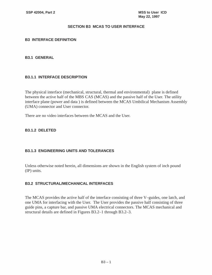
B3.1.1 INTERFACE DESCRIPTION
The physical interface (mechanical, structural, thermal and environmental) plane is definedbetween the active half of the MBS CAS (MCAS) and the passive half of the User. The utilityinterface plane (power and data ) is defined between the MCAS Umbilical Mechanism Assembly(UMA) connector and User connector.
There are no video interfaces between the MCAS and the User.
B3.1.2 DELETED
B3.1.3 ENGINEERING UNITS AND TOLERANCES
Unless otherwise noted herein, all dimensions are shown in the English system of inch pound(IP) units.
B3.2 STRUCTURAL/MECHANICAL INTERFACES
The MCAS provides the active half of the interface consisting of three V–guides, one latch, andone UMA for interfacing with the User. The User provides the passive half consisting of threeguide pins, a capture bar, and passive UMA electrical connectors. The MCAS mechanical andstructural details are defined in Figures B3.2–1 through B3.2–3.

SSP 42004, Part 2 MSS to User ICDMay 22, 1997
B3 – 2
B3.3 DELETED
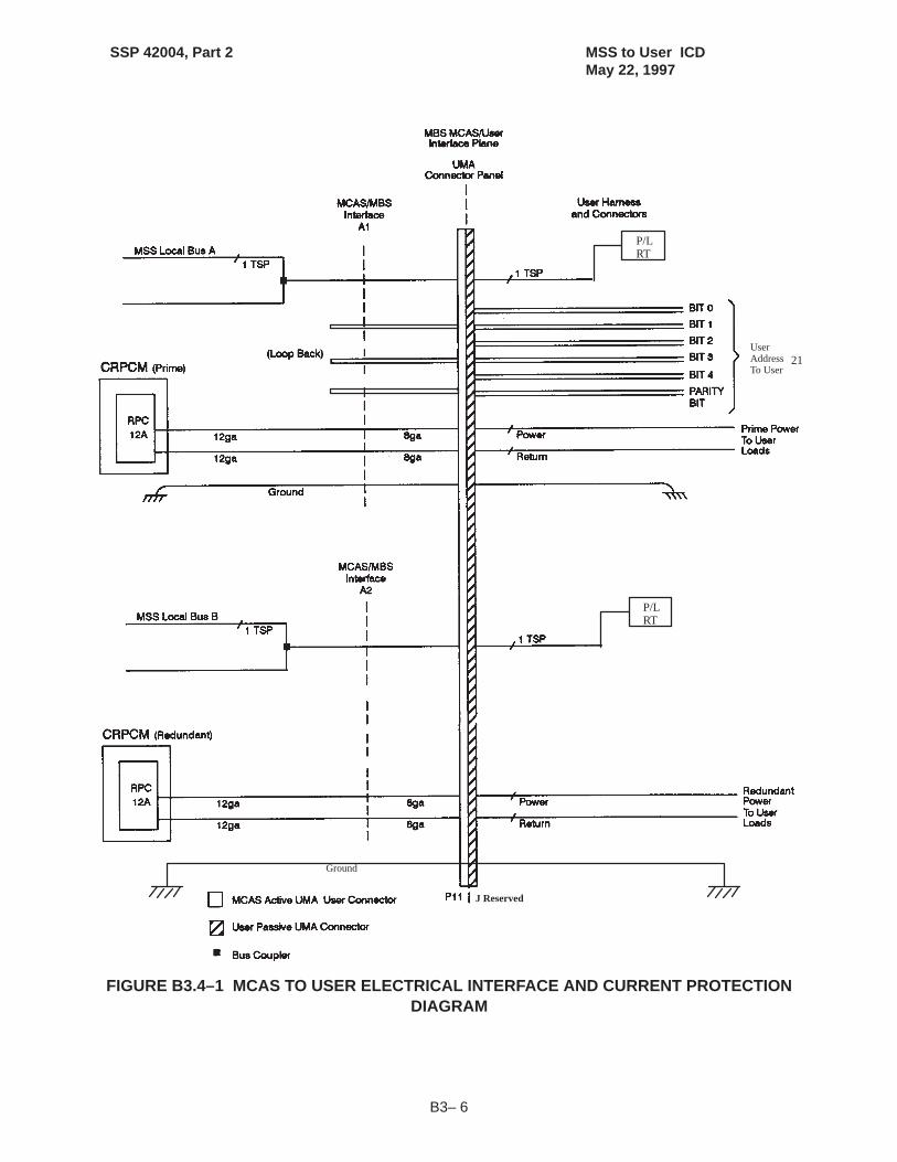
B3.4 ELECTRICAL INTERFACES
The MCAS to User power and data interfaces will be as defined in Figure B3.4–1.
B3.4.1 POWER, RETURN AND GROUNDING INTERFACES
The MCAS to User power, return and grounding interfaces will be as defined in Figure B3.4–1.
B3.4.2 POWER CONNECTORS AND PIN ASSIGNMENTS
The power connectors and pin assignments between the MCAS and the User will be as definedin Table B3.4.2–1.
B3.4.3 DATA INTERFACES
The C & DH subsystem will support data interfaces between the MCAS and the User as definedin Figure B3.4–1.
B3.4.3.1 DATA CONNECTORS AND PIN ASSIGNMENTS
The data connectors and pin assignments between the MCAS and the User will be as defined inTable B3.4.2–1.
B3.5 ENVIRONMENTS
The MCAS to User electromagnetic, grounding and bonding interface implementation will be asdefined in Figures B3.2–1 through B3.2–3.
B3.6 SOFTWARE INTERFACES
There are no software interfaces between the MCAS and the User.

SSP 42004, Part 2 MSS to User ICDMay 22, 1997
B3– 3
(Reference SPAR Drawing 51800–0025, Sheet 1 of 3)
FIGURE B3.2–1 MCAS TO USER MECHANICAL INTERFACE

SSP 42004, Part 2 MSS to User ICDMay 22, 1997
B3 – 4
(Reference SPAR Drawing 51800–0025, Sheet 2 of 3)
FIGURE B3.2–2 MCAS TO USER MECHANICAL INTERFACE

SSP 42004, Part 2 MSS to User ICDMay 22, 1997
B3–5
(Reference SPAR Drawing 51800–0025, Sheet 3 of 3)
FIGURE B3.2–3 MCAS TO USER MECHANICAL INTERFACE
SSP 42004, Part 2 MSS to User ICDMay 22, 1997
B3– 6
P/LRT
P/LRT
21UserAddressTo User
Ground
J Reserved
FIGURE B3.4–1 MCAS TO USER ELECTRICAL INTERFACE AND CURRENT PROTECTIONDIAGRAM

SSP 42004, Part 2 MSS to User ICDMay 22, 1997
B3– 7
TABLE B3.4.2–1 MCAS TO USER PRIME AND REDUNDANT POWER AND DATACHARACTERISTICS, CONNECTORS, AND PIN ASSIGNMENTS
ÁÁÁÁÁÁÁÁÁÁÁÁÁÁÁÁÁÁÁÁÁÁÁÁÁÁÁÁÁÁÁÁÁÁÁÁÁÁÁÁÁÁÁÁÁÁÁÁÁÁÁÁÁÁÁÁÁÁÁÁÁÁÁÁ
CONNECTOR IDÁÁÁÁÁÁÁÁÁÁÁÁÁÁÁÁÁÁÁÁÁÁÁÁÁÁÁÁÁÁÁÁÁÁÁÁÁÁÁÁÁÁÁÁÁÁÁÁÁÁÁÁÁÁ
MCASRef. Des: P11
ÁÁÁÁÁÁÁÁÁÁÁÁÁÁÁÁÁÁÁÁÁÁÁÁÁÁÁÁÁÁÁÁÁÁÁÁÁÁÁÁÁÁÁÁÁ
Part Number: NUP1–005
ÁÁÁÁÁÁÁÁÁÁÁÁÁÁÁÁÁÁÁÁÁÁÁÁÁÁÁÁÁÁÁÁÁÁÁÁÁÁÁÁÁÁÁÁÁÁÁÁÁÁÁÁÁÁ
UserRef. Des: J Reserved
ÁÁÁÁÁÁÁÁÁÁÁÁÁÁÁÁÁÁÁÁÁÁÁÁÁÁÁÁÁÁÁÁÁÁÁÁÁÁÁÁÁÁÁÁÁ
Part Number: Reserved
POWER AND DATA SPECIFICATIONS
ContactID SignalFunction
PeakPower2
(W)
MinimumVoltage
(VDC)
Current3
[A]
EMCClass
Power1)QualityType
WireGauge
(ga)
Remarks
TBD#12 LB A Hi NA NA NA RF NA 22 RT AD-DRESS 21
TBD#13 LB B Hi NA NA NA RF NA 22
TBD#12 LB A Lo NA NA NA RF NA 22
TBD#13 LB B Lo NA NA NA RF NA 22
TBD#12 User PowerBus 1
1350 112.5 12 EO C 8
TBD#13 User PowerBus 2
1350 112.5 12 EO C 8
TBD#12 Return 1 1350 112.5 12 EO C 8
TBD#13 Return 2 1350 112.5 12 EO C 8
TBD#12 Ground 1350 112.5 12 EO N/A 8
TBD#13 Ground 1350 112.5 12 EO N/A 8
Notes:1) The Transient Voltage Limits & Time Duration are as defined in SSP 30482, except for minimum voltage.
2) Table reflects design to peak power requirement and the associated minimum voltage defined at the MCAS UMAto User UMA interface plane.
3) Nominal rating of the MBS CRPCM output port.
4) Refer to SSQ 21635 for connector detailed specifications

SSP 42004, Part 2 MSS to User ICDMay 22, 1997
C3 – 1
SECTION C3 RESERVED
RESERVED

SSP 42004, Part 2 MSS to User ICDMay 22, 1997
D3 – 1
SECTION D3 RESERVED
RESERVED

SSP 42004, Part 2 MSS to User ICDMay 22, 1997
E3 – 1
SECTION E3 RESERVED
RESERVED

SSP 42004, Part 2 MSS to User ICDMay 22, 1997
F3 – 1
SECTION F3 RESERVED
RESERVED

SSP 42004, Part 2 MSS to User ICDMay 22, 1997
G3 – 1
SECTION G3 RESERVED
RESERVED

SSP 42004, Part 2 MSS to User ICDMay 22, 1997
H3 – 1
SECTION H3 RESERVED
RESERVED

SSP 42004, Part 2 MSS to User ICDMay 22, 1997
I3 – 1
SECTION I3 FRGF TO USER INTERFACES
I3 INTERFACE DEFINITION
The FRGF to user interface design details are documented in NSTS–21000–IDD–ISS, ShuttleOrbiter/International Cargo Standard Interfaces, Section 14.0.
SSP 42004, Part 2 MSS to User ICDMay 22, 1997
A – 1
APPENDIX A: ABBREVIATIONS AND ACRONYMS
AVF Artificial Vision Function
AVU Artificial Vision Unit
CAS Common Attach Structure
CCTV Closed Circuit Television
CSA Canadian Space Agency
DHT Dexterous Handling Target
EFGF Electrical Flight Grapple Fixture
EMI Electromagnetic Interference
EVA Extravehicular Activity
FRGF Flight Releasable Grapple Fixture
ft feet
Hz Hertz
ICD Interface Control Document
in inch
IP International Partner
kbps kilo bits per second
kg kilograms
kN–m kiloNewton–meter
kW kilowatt
lbs pounds
LEE Latching End Effector
m meter
mA milliamps
MBS MRS Base System

SSP 42004, Part 2 MSS to User ICDMay 22, 1997
A – 2
MC Micro Conical
MCAS MBS CAS
MCE MSS Control Equipment
MCF Micro Conical Fitting
MRS Mobile Remote Servicer
MSC Mobile Servicing Center
MSS Mobile Servicing System
MT Mobile Transporter
NASA National Aeronautics and Space Administration
N Newton
NSTS National Space Transportation System
ORU Orbit–Replaceable Unit
OTCM ORU/Tool Changeout Mechanism
OTP ORU/Tool Platform
PDGF Power and Data Grapple Fixture
PFM Pulse Frequency Modulation
POA Payload/ORU Accommodation
PSA Payload/ORU Support Assembly
PWP Portable Workplatform
rad Radian
RSGF Rigidize Sensing Grapple Fixture
RT Remote Terminal
SDGF Standard Dexterous Grasp Fixture
SEE Standard End Effector
SI Systems International
SPDA Secondary Power Distribution Assembly

SSP 42004, Part 2 MSS to User ICDMay 22, 1997
A – 3
SPDM Special Purpose Dexterous Manipulator
SPEE Special Purpose End Effector
SSCB Space Station Control Board
SSRMS Space Station Remote Manipulator System
TBD To Be Determined
TBR To Be Reviewed
TUS Trailing Umbilical System
UMA Umbilical Mechanism Assembly
Vdc Volts, direct current
W Watts

SSP 42004, Part 2 MSS to User ICDMay 22, 1997
B – 1
APPENDIX B: ISSUE SHEETS

SSP 42004, Part 2 MSS to User ICDMay 22, 1997
B – 2
ISSUE FORM, SPACE STATION
Issue Title:
Issue No.
Initiator Name:Org/Company:
Phone:Mailcode:
Date:Initiator’s Issue No:Problem Category:
(Mandatory only)
Document ID:Title:Date:
Page #:Sec. #:
Para. #:Fig. #:
Description of Issue:
Recommendation:
Impact if Recommendation Not Implemented:
Drawing Impact due to Change on Bonding Specification
42004–02–TC–01
Tom CraigBoeing/Huntsville205–461–6029
7/3/97
SSP 42004, Revision AMSS to User ICD, Part 25/22/97
A3–4A
A3.2–1
Previous versions of these documents have only required a Class H and R bond,which PG–3 implemented in their interface design. Note 9, added to this page sincethe February draft, imposes a specific implementation of the Class R bond which isdifferent from the one used in our released drawings. Although the change to hedrawing is minor in nature, we need authorization to make the change.

SSP 42004, Part 2 MSS to User ICDMay 22, 1997
B – 1
APPENDIX C: TBD LIST
1 A3.4 ELECTRICAL INTERFACES (SPDM) A3–2
2 A3.4.2 POWER CONNECTORS AND PIN ASSIGNMENTS (SPDM) A3–2
3 A3.7 PDGF STANDARD GRAPPLE TARGET AND AVF TARGET A3–3 2–21–97
4 TABLE A3.4.2–1 PDGF TO USER POWER FROM SSRMS (PRIME)CHARACTERISTICS, CONNECTORS, AND PIN ASSIGNMENTS
A3–13 2–21–97
5 TABLE A3.4.2–2 PDGF TO USER POWER FROM SSRMS (RE-DUNDANT) CHARACTERISTICS, CONNECTORS, AND PIN AS-SIGNMENTS
A3–14 2–21–97
6 TABLE A3.4.2–3 PDGF TO USER POWER FROM POA (PRIME)CHARACTERISTICS, CONNECTORS, AND PIN ASSIGNMENTS
A3–15 2–21–97
7 TABLE A3.4.2–4 PDGF TO USER POWER FROM POA (REDUN-DANT) CHARACTERISTICS, CONNECTORS, AND PIN ASSIGN-MENTS
A3–16 2–21–97
8 TABLE A3.4.3.1–1 PDGF TO USER DATA AND VIDEO FROMSSRMS (PRIME) CONNECTORS, AND PIN ASSIGNMENTS
A3–17 2–21–97
9 TABLE A3.4.3.1–2 PDGF TO USER DATA AND VIDEO FROMSSRMS (REDUNDANT) CONNECTORS, AND PIN ASSIGNMENTS
A3–18 2–21–97
10 TABLE A3.4.2–3 PDGF TO USER DATA AND VIDEO FROM POA(PRIME) CONNECTORS, AND PIN ASSIGNMENTS
A3–19 2–21–97
11 TABLE A3.4.2–4 PDGF TO USER DATA AND VIDEO FROM POA(REDUNDANT) CONNECTORS, AND PIN ASSIGNMENTS
A3–20 2–21–97
12 TABLE B3.4.2–1 MCAS TO USER PRIME POWER AND DATACHARACTERISTICS, CONNECTORS, AND PIN ASSIGNMENTS
B3–9 B3–9
13 TABLE B3.4.2–2 MCAS TO USER REDUNDANT POWER ANDDATA CHARACTERISTICS, CONNECTORS, AND PIN ASSIGN-MENTS
B3–10 B3–10