ml2150 - samsung printer guide
DESCRIPTION
Ml2150 - Samsung Printer GuideTRANSCRIPT

SERVICE
LASER PRINTERML-2150ML-2151NML-2152W
Manual
LASER PRINTER CONTENTS
1. Precautions
2. Reference Information
3. Specifications
4. Summary of product
5. Disassembly and Reassembly
6. Alignment and Adjustments
7. Troubleshooting
8. Exploded Views and Parts List
9. Block Diagram
10. Connection Diagram

11
1-1Samsung Electronics
Precautions
Service Manual
1. PrecautionsThe cautions in the below are items needed to keep in mind when maintaining and servicing.Please read carefully and keep the contents in mind to prevent accidents while servicing and preventany damages to the damage.
1.1 Warning for safety.
(1) Request the service by qualified service person.The service for this machine must be performed by a service person who took the additional education ofthis field. It is dangerous if unqualified service person or user tries to fix the machine.
(2) Do not rebuild it discretionary. Do not attach or change parts discretionary. Do not disassemble, fix, and rebuilt it. If you do, printer will notwork and electric shock or a fire can be occurred.
(3) Laser Safety StatementThe Printer is certified in the U.S. to conform to the requirements of DHHS 21 CFR, chapter 1 Subchapter Jfor Class 1(1) laser products, and elsewhere, is certified as a Class I laser product conforming to therequirements of IEC 825. Class I laser products are not considered to be hazardous. The laser system andprinter are designed so there is never any human access to laser radiation above a Class I level during nor-mal operation, user maintenance, or prescribed service condition.
Warning >> Never operate or service the printer with the protective cover removed from Laser/Scanner assembly. The reflectedbeam, although invisible, can damage your eyes. When using this product, these basic safety precautions shouldalways be followed to reduce risk of fire, electric shock, and injury to persons.
CAUTION - INVISIBLE LASER RADIATION WHEN THIS COVER OPEN. DO NOT OPEN THIS COVER.
VORSICHT - UNSICHTBARE LASERSTRAHLUNG, WENN ABDECKUNG GE FFNET. NICHT DEM STRAHL AUSSETZEN.
ATTENTION - RAYONNEMENT LASER INVISIBLE EN CAS D OUVERTURE. EXPOSITION DANGEREUSE AU FAISCEAU.
ATTENZIONE - RADIAZIONE LASER INVISIBILE IN CASO DI APERTURA. EVITARE L ESPOSIZIONE AL FASCIO.
PRECAUCION - RADIACION LASER IVISIBLE CUANDO SE ABRE. EVITAR EXPONERSE AL RAYO.
ADVARSEL. - USYNLIG LASERSTR LNING VED BNING, N R SIKKERHEDSBRYDERE ER UDE AF FUNKTION. UNDG UDSAETTELSE FOR STR LNING.
ADVARSEL. - USYNLIG LASERSTR LNING N R DEKSEL PNES. STIRR IKKE INN I STR LEN. UNNG EKSPONERING FOR STR LEN.
VARNING - OSYNLIG LASERSTR LNING N R DENNA DEL R PPNAD OCH SP RREN R URKOPPLAD. BETRAKTA EJ STR LEN. STR LEN R FARLIG.
VARO! - AVATTAESSA JA SUOJALUKITUS OHITETTAESSA OLET ALTTIINA N KYM TT M LLE LASER-S TEILYLLE L KATSO S TEESEEN.

1-2
Precautions
Samsung ElectronicsService Manual
1.2 Caution for safety
1.2.1 Precaution related noxious material
There is a possibility to get harm from noxious material if you ignore the below information.
(1) Do not touch the damaged LCD. This PRINTER has LCD in control panel. Noxious liquid to human body exists in theLCD. If it gets into your mouth, immediately see a doctor. If it gets into eyes or on skin, immediately wash it off formore than 15 minutes with flowing water and see a doctor.
(2) The toner in a printer cartridge contains a chemical material, which might harm human body if it is swallowed.Please keep children out of the toner cartridge.
1.2.2 Precaution related electric shock or fire
It is possible to get electric shock or burn by fire if you don't fallow the instructions of the manual.
(1) Use exact voltage. Please do use an exact voltage and wall socket. If not, a fire or an electric leakage can becaused.
(2) Use authorized power cord. Do use the power cord supplied with PRINTER. A fire can occur when over currentflows in the power cord.
(3) Do not insert many cords in an outlet. If you do, a fire can be occurr due to flow over current over flow in an out-let.
(4) Do not put water or extraneous matter in the PRINTER. Please do not put water, other liquid, pin, clip, etc. It cancause a fire, electric shock, or malfunction. If it happens, turn off the power and remove the power plug from theoutlet immediately.
(5) Do not touch the power plug with wet hands. When servicing, do remove the power plug from outlet. And do notinsert or take off it with wet hands. Electric shock can be occur.
(6) Caution when inserting or taking off the power plug. The power plug has to be inserted completely. If not, a firecan be caused due to poor contact. When taking off the power plug, do grip the plug and take it off. If grip the lineand pull over, it could be damaged. This could cuase a fire or electric shock.
(7) Management of power cord. Do not bend, twist, or bind it and place other materials on it. Also, do not fix it withstaples. If the power cord gets damage, a fire or electric shock can be caused. A damaged power cord must bereplaced immediately. Do not repair the damaged part and reuse it. A repaired part with plastic tape can beoccurred a fire or electric shock. Do not spread chemicals on the power cord. Do not spread insecticide on thepower cord. A fire or electric shock can be occurred due to thinner(weak) cover of the power cord.
(8) Check whether the power outlet and the power plug are damaged, pressed, chopped, or on fire. When such poorconditions are found, repair it immediately. Avoid pressure or cut when moving the machine.
(9) Caution when thundering, and being flash of lightening. It causes a fire or electric shock. Take the power plug offwhen thundering. Do not touch cable and device when thundering and being flash of lightening.
(10) Avoid places where there is moisture or dust. Do not install the printer in a place where lots of dusts or humidi-fier are around. A fire can occur. A plug part needs to be cleaned well with dried fabric to remove dust. If waterdrops are dripped on the place cover with dust, a fire can occur.
(11) Avoid direct sunlight. Do not install the printer near to window where directly contacts to the sunlight. If themachine contacts sunlight long time, the machine cannot work properly because inner temperature of themachine is getting higher. A fire can be caused.
(12) Turn off the power and take off the plug when a smoke, strange smell, or sound from the machine. If you keepusing it, a fire can occur.
(13) Do not insert steel or metal piece inside/outside of the machine. Do not put steel or metal piece into a ventila-tor. An electric shock can happen.

1-3Samsung Electronics
Precautions
Service Manual
1.2.3 Precaution related handling the machine.
If you ignore this information, you get hurt and machine could be damaged.
(1) Do not install unit on uneven surfaces or slanted floors.
Please confirm that unit is correctly balanced after installation. Machine may fall over when itis not bal-
anced correctly.
(2) Be careful not to insert a finger or hair in the rotating unit.
Be careful not to insert a finger of hair in the rotating unit (motor, fan, paper feeding part, etc) while the
machine is operating. Once it happens, you could harm.
(3) Do not place any containers of water/chemical or small metals. If those are got into the inner side of
machine, a fire or electric shock can occur.
(4) Do not install machine in areas where moisture or dust exists. For example, do not install machine near
open windows, damage maybe caused by these conditions.
(5) Do not place a candle, burning cigarettes, and etc. on the machine. Do not install it near to a heater. A fire
can occur.
1.2.4 Precaution when assembly/disassembly
When replace parts, do it very carefully. Do memorize the location of each cable before replace parts forreconnecting it afterwards. Do memorize. Please perform the below before replace or disassemblying anyparts.
(1) Check the contents stored in the memory. All the information will be erased after replace main board. The
information needed to keep has to be written down.
(2) Remove printer cables and power cord.
(3) Take off printer cables and power code connected to printer.
(4) Do use formal parts and same standardized goods when replacing parts.Must check the product name,
part cord, rated voltage, rated current, operating temperature, etc.
(5) Do not give an over-force when release or tighten up the plastic parts.
(6) Be careful not to drop the small parts such as screws in the printer.
(7) Be careful not to change the location of small parts such as screws when assembling and disassembling.
(8) Do remove dust or foreign matters completely to prevent fire of tracking, short, or etc.
(9) After finished repair, check the assembled state whether it is the same as before the repair or not.

1-4
Precautions
Samsung ElectronicsService Manual
1.3 ESD Precautions
Certain semiconductor devices can be easily damaged by static electricity. Such components are commonlycalled “Electrostatically Sensitive (ES) Devices”, or ESDs. Examples of typical ESDs are: integrated circuits,some field effect transistors, and semiconductor “chip” components.The techniques outlined below should be followed to help reduce the incidence of component damage causedby static electricity.
Caution >>Be sure no power is applied to the chassis or circuit, and observe all other safety precautions.
1. Immediately before handling a semiconductor component or semiconductor-equipped assembly, drain off
any electrostatic charge on your body by touching a known earth ground. Alternatively, employ a commer-
cially available wrist strap device, which should be removed for your personal safety reasons prior to apply-
ing power to the unit under test.
2. After removing an electrical assembly equipped with ESDs, place the assembly on a conductive surface,
such as aluminum or copper foil, or conductive foam, to prevent electrostatic charge buildup in the vicinity
of the assembly.
3. Use only a grounded tip soldering iron to solder or desolder ESDs.
4. Use only an “anti-static” solder removal device. Some solder removal devices not classified as “anti-static”
can generate electrical charges sufficient to damage ESDs.
5. Do not use Freon-propelled chemicals. When sprayed, these can generate electrical charges sufficient to
damage ESDs.
6. Do not remove a replacement ESD from its protective packaging until immediately before installing it. Most
replacement ESDs are packaged with all leads shorted together by conductive foam, aluminum foil, or a
comparable conductive material.
7. Immediately before removing the protective shorting material from the leads of a replacement ESD, touch
the protective material to the chassis or circuit assembly into which the device will be installed.
8. Maintain continuous electrical contact between the ESD and the assembly into which it will be installed,
until completely plugged or soldered into the circuit.
9. Minimize bodily motions when handling unpackaged replacement ESDs. Normal motions, such as the
brushing together of clothing fabric and lifting one’s foot from a carpeted floor, can generate static electric-
ity sufficient to damage an ESD.

22
2-1Samsung Electronics
REFERENCE INFORMATION
Service Manual
2. Reference Information
This chapter describes the reference information for applying this training manual, and it is consist-ed of the tool list, the abbreviation table, the outline of model, and so on.
2.1 Tool for Troubleshooting
The following tools are recommended for safe and smooth troubleshooting described in this service manual.
DriverStandard : "-" type, "+" type (M3 long, M3 short, M2 long,
M2 short).
4
Cotton SwabStandard : For general home use, for medical ser-vice
6
Software(Driver) installation CD ROM3 Cleaning Equipments a IPA(IsopropylAlcohol)dry cloth or a soft stuff neutraldetergent
8
Spring HookStandard : For general use
7
TweezersStandard : For general home use, small type.
5
DVM(Digital Volt Meter)Standard : Indicates more than 3 digits.
1
Electronic ScaleStandard : Equipment to check the weight of con-sumables(toner cartridge) supplied by SamsungElectronics. (The gram unit can be measured.)
2
Keep your hands not to be touched whenyou disassemble and reassemble PBAASS'Y, such as the main board, SMPS,HVPS.

2-2
REFERENCE INFORMATION
Samsung ElectronicsService Manual
2.2 Acronyms and Abbreviations
The table in the below explains abbreviations used in this service manual.The contents of this service manual are declared with abbreviations in many parts. Please refer to thetable.
AC Alternating Current
AP Access Point
ASIC Application Specific Integrated Circuit
ASSY assembly
BIOS Basic Input Output System
CMOS Complementary Metal OxideSemiconductor
CN connector
CON connector
CPU Central Processing Unit
dB decibel
dbA decibelampere
dBM decibel milliwatt
DC direct current
DCU Diagnostic Control Unit
DPI Dot Per Inch
DRAM Dynamic Random Access Memory
DVM Digital Voltmeter
ECP Enhanced Capability Port
EEPROM Electronically Erasable ProgrammableRead Only Memory
EMI Electro Magnetic Interference
EP electrophotographic
EPP Enhanced Parallel Port
F/W firmware
GDI graphics device interface
GND ground
HBP Host Based Printing
HDD Hard Disk Drive
HV high voltage
HVPS High Voltage Power Supply
I/F interface
I/O Input and Output
IC integrated circuit
IDE Intelligent Drive electronics or ImbeddedDrive Electronics
IEEE Institute of Electrical and Electronics
Engineers. Inc
IPA Isopropy Alcohol
IPM Images Per Minute
LAN local area network
lb pound(s)
LBP Laser Beam Printer
LCD Liquid Crystal Display
LED Light Emitting Diode
LSU Laser Scanning Unit
MB megabyte
MHz megahertz
MPF Multi Purpose Feeder
NIC Network Interface Card
NVRAM nonvolatile random access memory
OPC Organic Photo Conductor
PBA Printed Board Assembly
PCL Printer Command Language , PrinterControl Language
PDL Page Discription Language
PPM Page Per Minute
PS Post Script
PTL Pre-Transfer Lamp
Q-PID Quick Printer Initiating Device
Q ty quantity
RAM Random Access Memory
ROM Read Only Memory
SCF Second Cassette Feeder
SMPS Switching Mode Power Supply
SPGP Samsung Printer Graphic Processor
SPL Samsung Printer Language
Spool Simultaneous Peripheral Operation Online
SW switch
sync synchronous or synchronization
USB Universal Serial Bus
WECA Wireless Ethernet Compatibility Alliance

2-3Samsung Electronics
REFERENCE INFORMATION
Service Manual
2.3 Selecting a Location
Select a level,stable place with adequate space for air circulation.Allow extra space for opening covers andtrays. The area should be well-ventilated and away from direct sunlight or sources of heat,cold,and humidi-ty.Do not set the printer close to the edge of your desk or table.
CLEARANCE SPACE
• Front : 482.6 mm (enough space so that trays can be removed)• Back : 320 mm (enough space to allow opening of the rear cover)• Right :100 mm• Left :100 mm (enough space for ventilation)

2-4
REFERENCE INFORMATION
Samsung ElectronicsService Manual
2.4 The Sample Pattern for the Test
The sample pattern shown in below is the standard pattern used in a factory.The contents of the life span and the printing speed are measured with the pattern shown in below.(The picture in the manual is 70% size of the actual A4 size.)
2.4.1 A4 5% Patten

2-5Samsung Electronics
REFERENCE INFORMATION
Service Manual
2.4.2 A4 2% Patten

2-6
REFERENCE INFORMATION
Samsung ElectronicsService Manual
2.4.3 A4 IDC 5% Patten

2.6 Wireless LAN
• This product uses a printing function with a wireless LAN, which is an option. - The wireless LAN function uses a frequency instead of connecting LAN cable to connect data to
an access point for print.- For a wireless LAN connection, an AP is needed, It is possible to use wireless LAN onnection with
wired LAN. Also, if AP is installed in an office or at home, the wireless LAN function can be simplyused.
• Types of desk top PC (or Lap top) that uses the wireless LAN.
• About the certificated mark of Wi-FiTM
- The Wi-FiTM is a registered trademark of WECA (Wireless EthernetCompatibility Alliance). Over 50 of a wireless LAN companies are memberof it. The most of main wireless networking companies are attending andthe main companies are Lucent technologies, Cisco, Intel/Symbol, 3Com,Enterasys (Cabletron), Compaq, IBM, Nokia, Dell, Philips, Samsung elec-tronic, Sony, Intersil, and so on. This mark certifies mutual compatibilityamong product has Wi-FiTM (IEEE 802.1) and it is certified as a standard ofa wireless LAN market.
Division Basic type Recommend type
CPU Over PENTIUM 233M PENTIUM 300MHz
MEMORY Over 64MB Over 128MB
VIDEO CARD Over 800X600 Over 1024X768
OS Over WINDOWS 98 Over WINDOWS ME
INTERFACE CARD A product has a certificated mark of Wi-FiTM
2-7Samsung Electronics
REFERENCE INFORMATION
Service Manual

2-8
REFERENCE INFORMATION
Samsung ElectronicsService Manual

33
3-1Samsung Electronics
Specifications
Service Manual
3. SpecificationsProduct specifications are subject to change without notice.See below for product specifications.
3.1 General SpecificationsITEM DESCRIPTION
Print Method Non-impact Electro-photography
Development system Non-Magnetic, Mono-Component Toner
Transfer system Conductive roller transfer
Fuser Unit(Toner fix) Pressure and Heating with Lamp
*Print Speed Up to 20 PPM in A4 size, IDC 5% pattern
Up to 21 PPM in A4 size, IDC 5% pattern
Resolution Up to 600 x 600 DPI
Up to 1200 x 1200 DPI
Source of Light Laser diode (LSU : Laser Scanner Unit)
Warm-Up Time Power-on boot : 50 seconds or less
First Print Time 13 seconds or less
Feed Method Cassette & Manual , Option Feeder(SCF)
Media Size 76mm * 128mm(3 * 5”) to 216mm * 356mm(8.5 *14”)
Media Thickness Cassette : 16 ~ 28 lb, Manual : 16 ~43lb
Dimension(W X D X H) 480 X 522 X 516mm / 18.9 X 20.6 X 20.3 inch (without option cassette)
Weight Net : 13 Kg
Gross : 15.5 Kg
**Acoustic Noise Stand by : Less than 35 dB
Printing: Less than 53 dB
Sleep mode : Background Noise
Power save mode Enable
Toner save mode Enable
Consumption Parts Pick Up Roller Up to 100,000 pages
Transfer Roller Up to 100,000 pages
Fuser Assembly Up to 100,000 pages
Optional Parts SCF Paper Capacity : 500 Sheets
NIC Ethernet 10/100 base TX
(Ml-2150:Optional Protocols : TCP/IP, SPX/IPX, Ethertalk, SNMP,
ML-2151N : Basic) HTTP1.1, DLC/LLC
16MB RAM Buffer for faster graphics performance
2MB Flash Memory for upgrade
Throughput : 200 ~ 300K TCP/IP
SDRAM DIMM 16, 32, 64, 128MB 100PIN SDRAM DIMM
Postscript Flash ROM 4MB
802.11b Wireless LAN IEEE802.3b supportT
(ML-2152W Basic) Speed : 11, 5.5, 2, 1 Mbps
Protocol : CSMA/CD
Operation range : 30m(Indoors), 150m(Outdoors)

3-2
Specifications
Samsung ElectronicsService Manual
3.3 Electrical Specification
ITEM DESCRIPTION REMARK
Input Voltage Nominal input voltage 200-240 VAC / 100~127VAC
Input voltage range 189-264 VAC/ 90~132VAC
Nominal frequency 50/60 MHz
Frequency tolerance +3Hz
Power Consumption Printing : 350W Avg or less (without SCF) , 400W Avg or less (with SCF)
Idling : 100W Avg or less
Power Save : 15W Avg or less
3.2 Controller SpecificationITEM DESCRIPTION
Processor(CPU) ARM946E-S (CLOCK SPEED 166Mhz)
Memory FLASH ROM(PROGRAM) : 2MB flash
RAM : 16MB (Expandable to 144MB)
Option DIMM module : 16,32,64,128MB (SDRAM)
100Pin SDRAM DIMM (Samsung Printer Only)
EEPROM(NVRAM) : 512byte
Emulation PCL6 : Win9x/ME/NT4.0/2000/XP, Various Linux OS including Red Hat, Caldera,Debian, Mandrake, Slackware, SuSE and Turbo Linux
MAC OS 8.6 ~ 9.2/10.1 ~ 10.3
Various Linux OS including Red Hat, Caldera, Debian, Mandrake, Slackware, SuSE and Turbo Linux
Interface Parallel : IEEE 1284 Bidirectional Parallel
- Modes supported : Compatible,Nibble,Byte,ECP
USB(without HUB mode)
-USB 2.0 compliant -12 Mbps 1 port
Serial : RS-232C
Network Interface : option for ML-2150
-10/100 Base TX -10/100 Base TX 802.11b Wireless LAN (option for ML-2151N)
Interface switching Automatic
Interface time-out 5min(Max.)
Font 45 Scalable Font , 1 Bitmap Font ,Postscript 3 internal font 136
3.4 TONER Cartridge (Developer)
ITEM DESCRIPTION REMARK
Life span Starter: Up to 4,000 sheets A4 Size, IDC 5% pattern, SIMPLEX
Running : Up to 8,000 sheets
Developing Non-magnetic Contact Developing
Charging Conductive Roller Charging
Toner supply Method Exchange the Developer
Toner checking sensor Enable
Ozone 0.1PPM or less
Style Single cartridge

3-3Samsung Electronics
Specifications
Service Manual
3.6 Paper Handling Specifications
>> Input Paper Size
>> Input capacity
>> Output capacity
PAPER PAPER SIZE 1ST CASSETTE 2ND CASSETTE MP TRAY DUPLEX
A4 210 X 297 mm O O O O
Letter 216 X 279(8.5 X 11") O O O O
Folio(Legal13") 216 X 330(8.5 X 13") O O O O
Legal(Legal14") 216 X 356(8.5 X14") O O O O
Executive 184 X 267((7.25 X10.5") O O
Statement 140 X 216(5.5 x8.5") O
ISO B5 176 X 250 O O
JIS B5 182 X257 O O
A5 148.5 X 210 O O
A6 105 X148.5 O
Com-10 Envelope 105 X 241(4.15 X 9.5") O
Monarch Envelope 98 X191(3.87 X 7.5") O
DL Envelope 110 X 220(4.33 X 8.66") O
C5 Envelope 162 X 229(6.38 X 9.01") O
C6 Envelope 114 X 162(4.49 X 6.38") OTransparency(OHP) A4 or Letter O
Label paper A4 or Letter O
O : Enable
ITEM DESCRIPTION
Cassette 500sheets
MP tray Paper 100 sheets
Transparencies 25 sheets
Envelopes 10 sheets
Labels 25 sheets
Option Cassette 500sheets
ITEM DESCRIPTION
Face Down 250 sheets
Face UP 100 sheets
3.5 Environmental ConditionITEM OPERATING STORAGE
Temperature 10~30 oC(50-90 oF) -20~40 oC (-4~104 oF)
Humidity 20~80%RH 10~80%RH

3-4
Specifications
Samsung ElectronicsService Manual

Summary of Product
Service Manual 4-1Samsung Electronics
444. Summary of ProductThis chapter describes the functions and operating principal of the main component.
4.1 Printer Components
4.1.1 Front View
Toner cartridge
(needed to access the control board to install printer options)
(Face down)
(500-sheet paper feeder)
(500-sheet paper feeder)
Control Panel
Top Cover
Paper level indicator
Control board cover
Multi-Purpose Tray
Output Support
Top output tray
Tray1
Optional Tray2

Service Manual
Summary of Product
4-2Samsung Electronics
4.1.2 Rear View
Rear output tray(Face up)
Power receptacle
Parallel port
USB port
Power switch
Network port(ML-2550:Option
ML-2551N, ML-2552W: Standard)
Wireless networkantenna port
(ML-2550, ML-2551N:OptionML-2552W:Standard)
Optional Tray2cable connector

Summary of Product
Service Manual 4-3Samsung Electronics
Display : displays theprinter status and job inprogress.
Buttons
4.1.3 Control Panel
The control panel on the top right side of your printer has the display and the nine buttons.
4.1.3.1 Display
Message Description
Ready • The printer is on-line and ready to print.
• If you press On-Line/Continue ,the printer switches to off-line.
Offline • The printer is off-line and cannot print.
• If you press On-Line/Continue ,the printer switches to on-line.
Printing XXX • The printer is printing.
* xxx is the current • If you want to cancel printing,press Cancel .
emulation.
Sleeping... • The printer is in Power Save mode, consuming less power. When a print job is received
from the computer or if any button is pressed,the printer switches to on-line.

Service Manual
Summary of Product
4-4Samsung Electronics
4.1.3.2 Buttons
Button Description
• Press to switch between on-line and off-line.
• In menu mode,press to return to ready mode.
You can check the printer status according to the button backlight.
Green On The printer is on-line and can receive data from the computer.
Blinking • When the backlight slowly blinks,the printer is receiving data
from the computer.
• When the backlight fast blinks,the printer is receiving and print-
ing data.
If you want to pause printing, switch the printer to off-line.
Orange On The printer stops printing due to a major error.Check the display
message.
Blinking A minor error occurs and the printer is waiting an error to be
cleared.Check the display message.When the problem is
cleared,the printer resumes printing.If you want to ignore this
warning,press this button.
Off • The printer is off-line and cannot print.
• The printer is in Power Save mode.
When data is received,it switches to on-line.
• Press to enter menu mode.
• In menu mode,press to scroll through the menus.
In menu mode,press to select the displayed submenu item or confirm the changed set-
ting. You can see the selected value marked with *.
In menu mode,press to scroll through submenu items or setting options. Pressing moves
you to the next option and pressing sends you back to the previous option.
• Press to cancel the current print job.
• In menu mode,press to return to ready mode.
In menu mode,press to go back to the upper menu level.
Press to enable or disable Toner Save mode.
• If the button backlight is on,the mode is enabled and the printer uses less toner to print
a document.
• If the button backlight is off,the mode is disabled and the printer will print in the normal
quality.
For more information on the Toner Save mode.
Press to enable or disable the double-sided printing.
• If the button backlight is on,the printer print on both sides of paper with long edge bind-
ing.
• If the button backlight is off,the double-side printing is disabled and the printer prints on
one side of paper.
Note : The double-sided printing setting in the printer driver overrides that of the controlpanel.

Summary of Product
Service Manual 4-5Samsung Electronics
4.1.3.3 Using Control Panel Menus
A number of menus are available to make it easy for you to change printer settings.
Accessing Control Panel Menus
You can control your printer from the printer ’s control panel. You can also set the control panel menus while the printer is
in use.
1. Press the Menu button until you see the desired menu on the bottom line of the display or Press the scroll but-
ton until the desired menu item displays on the bottom line.
2. Press the Enter button to access the menu.
3. Press the scroll button until the desired menu item displays on the bottom line.
4. Press the Enter button to confirm the selected item.
5. If the selected menu item has submenus,repeat steps 3 and 4.
6. Press the scroll button until the desired setting option displays on the bottom line or enter the required value.
7. Press the Enter button to save your input or selection.
An asterisk (*) appears next to the selection on the display, indicating that it is now the default.
8. To exit the menu,press the Upper Level button repeatedly,or the Cancel button .
After 60 seconds of inactivity (no key has been pressed), the printer automatically returns to ready mode.
NOTE : Duplicate print settings that are selected in the printer driver override the settings on the control panel.

Service Manual
Summary of Product
4-6Samsung Electronics
4.1.3.4 Overview of Control Panel Menus
The control panel menus are used to configure the printer for your environment.The control panel provides access to the following menus.
Paper
Tray SourceMedia SizeCustom WidthCustom HeighMedia TypeTray Chaining
Layout
OrientationDuplexDuplex MarginSimplex MarginCopies
Setup
LCD LanguageEmulationPower SaveAuto ContinueJam Recovery
Altitude Adj.Auto CRJob Time OutRS-232CMaintenance
Printer
Default SetCurrent Job
Information
ConfigurationMenu MapDemo PagePS3 Font ListPCL Font ListEPSON Fonts
Graphics
ResolutionImage EnhanceToner SaveDensity
EPSON
FontAuto WrapCharacter SetCharacter Tab.LPIPitch
PCL
TypefaceSymbolLinesPitchPoint SizeCourier
PostScript
Print PS. Error
NETWORK
Config NetworkConfig TCP/IPDHCPIP Address SetIP AddressSubnet MaskGatewayBOOTP
AppleTalkNetwareConfig NetwareAUTOEN_8023EN_IIEN_8022EN_SNAP
Reset NetworkDefault SetPrint Net CFGRX Level

Summary of Product
Service Manual 4-7Samsung Electronics
4.1.3.5 Special Features
Your new printer is equipped with special features that improve the print quality,giving you a competitive edge.You can:
Print with excellent quality and high speed
• You can print at 1200 dots per inch (dpi).See page 5.25.
• Your printer prints 21 pages-per-minute (Letter size), 20 pages-per-minute (A4 size).
Handle paper flexibly
• A 100-sheet Multi-Purpose Tray supports letterheads, envelopes,labels,transparencies,cus-tom-sized materials,postcards,and heavy paper.
• Standard 500-sheet input tray (Tray1)and optional 500-sheet input tray (Tray2)supports allstandard sizes of paper.
• Two output tray;select either the top output (face-down)or the rear output tray (face-up)forthe most convenient access.
• Straight-through paper path capability from the Multi-Purpose Tray to the rear output tray.
Create professional documents
• You can customize your documents using Watermarks, such as “Confidential.”
• Print Booklets .This feature enables you to easily print the pages required to createbooks.Once printed,all you have to do is to fold and staple the pages.
• Print Posters .The text and pictures of each page of your document are magnified and print-ed across the selected sheet of paper.After the document has printed,trim off the whiteedges of each sheet.Tape the sheets together to form a poster.
Save your time and money
• This printer allows you to use Toner Save mode to save toner.
• You can print on both sides of the paper to save paper (double-sided printing ).
• You can print multiple pages on one single sheet of paper to save paper (N-Up printing ).
• Preprinted forms and letterheads can be printed on plain paper.
• This printer automatically conserves electricity by substantially reducing power consumptionwhen not printing.
• This printer meets Energy Star guidelines for energy efficiency.
()

Service Manual
Summary of Product
4-8Samsung Electronics
Expand the printer capacity
• This printer has 32 MB of memory which can be expanded to 160 MB.
• Network interface enables network printing.You can add the optional network interface cardto ML-2550.
ML-2551N and ML-2552W comes with a built-in network interface,10/100 Base TX.ML-2552W also has a wireless network interface.
* PostScript 3 EmulationIPS-PRINT_Printer language Emulation © Copyright1995-2003,Oak Technology,Inc.,All rights reserved
* 136 PS3 fontsContains UFST and MicroType from Agfa Monotype Corporation.
Print in various environments
• You can print in Windows 95/98/Me/NT 4.0/2000/XP .
• Your printer is compatible with Linux and Macintosh .
• Your printer comes with both the Parallel and USB interfaces.
You can also use a network interface .ML-2551N and
ML-2552W comes with a built-in network interface,10/100 Base TX.ML-2552W also has awireless network interface. But, you need to add the optional network interface card to ML-2550.
Printer Features
The table below lists a general overview of features supported by your printer.
Features ML-2550 ML-2551N ML-2552W
IEEE 1284 STANDARD STANDARD STANDARD
USB 2.0 STANDARD STANDARD STANDARD
Network Interface OPTION STANDARD STANDARD
Wireless LAN OPTION OPTION STANDARD
PostScript Emulation STANDARD STANDARD STANDARD

Summary of Product
Service Manual 4-9Samsung Electronics
4.2 System Layout
P/RP/R
H/RH/R
Transfer ransfer RollerRoller
Pick up Pick up RollerRoller
Pick up Pick up Roller(MP)Roller(MP)
OPCOPC
P/R
H/R
Transfer Roller
Pick up Roller
Pick up Roller(MP)
RegiRegiRollerRollerRegiRoller
RetardRetardRollerRollerRetardRoller
OPC
5
6
7
8
1
2
3
4
Toner Cartridge Exit Motor
LSU5Cassette1
Fuser6Duplex Unit2
Main Motor7MPF3
84

Service Manual
Summary of Product
4-10Samsung Electronics
4.2.1 FeedingIt is consists of a basic cassette, an MP tray for supplying different types of media : envelope, label spe-cial paper, duplex unit, and parts related to paper transferring.
1) Separation methodSeparate it from the finger mounted to the cassette side guide and apply retard roller that uses aspring clutch. A feed roller uses an electronic clutch to control driving power.
2) Basic cassetteIt takes a center loading method and applies 'both side finger separating method.' It means thatthere is a paper sensor, but a paper size is detected after detecting the first paper by software. Both the side guide and the rear guide can be adjusted for for various types of papers from A5 tolegal size paper.It has a paper existence sensing function (Capacity: 500 sheets of general paper), paper arrangingfunction, various size papers accepting function, SCF paper path function, and displaying functionof paper remaining amount.In the front side, there is a paper level indicator.
3) Pick-up rollerIt has functions such as a paper pickup function, driving control function, paper feeding function,and removing electronic static function.
4) Retard rollerIt takes an arrangement method which uses a stopper roller and a weight without electric actuator.Ithas paper separating function, driving control function, and multi feeding prevention function.
6) Registration rollerIt has a paper arranging function, paper transferring function, paper detecting function, jam remov-ing function, and so on.
7) MP trayIt has a paper arranging function, paper transferring function, jam removing function, and so on.It uses rubbing pad method to feed 100 sheets of general papers and 100 envelops. It is possible to extend to 300mm for accepting a legal size paper.
8) Duplex unitIt has paper transferring function, paper guide function, jam removing function, paper sensing func-tion, and main board supporting function.It is designed for basic attachment, and the duplex feeding takes a side feeding method. Usable
papers are A4, letter, and legal size paper.For removing a jam occurred in a front part, it is designed to open a cassette and a guide. It isdesigned to open a rear cover to remove a jam in a rear part.If a face up tray is open, the duplex option cannot be used.
9) SCF (Second Cassette Feeder)It is the same method with the main cassette, and the capacity is 500 sheets.It has a separate driving mechanism and feeds only A4, letter, and legal size paper.It is designed for a common use with a main cassette, but it cannot be attached with the main cas-sette.

Summary of Product
Service Manual 4-11Samsung Electronics
4.2.2 TransferIt consists of a PTL (Pre-transfer Lamp) and a transfer roller. A PTL sheds light on an OPC drum, lowersan electric potential of an OPC drum's surface, and improves the efficiency of the transfer.A transfer roller transfers toner on an OPC drum to the paper.Life span: Print over 100,000 sheets (In 15~30(C)
4.2.3 Driver Ass'yBy driving the motor, the system takes power. It is consisted of a main motor for feeding and a toner car-tridge, and sub-motors for fuser and duplex reverse turn.
4.2.4 FuserIt is consisted of a heat lamp, heat roller, pressure roller, thermistor and thermostat. It sticks the toner ona paper by heat and pressure to complete the printing job.
1) ThermostatWhen a heat lamp is overheated, a Thermostat cuts off the main power to prevent over-heating.
3) Heat rollerThe heat roller transfers the heat from the heat lamp to apply a heat on the paper. The surface ofa heat roller is coated with Teflon, so toner does not stick to the surface.
4) Pressure rollerA pressure roller mounted under a heat roller is made of a silicon resin, and the surface also iscoated with Teflon. When a paper passes between a heat roller and a pressure roller, toneradheres to the surface of a paper permanently.
5) Items for safetyProtecting device for overheating
- 1st protection device: Hardware cuts off when overheated- 2nd protection device: Software cuts off when overheated- 3rd protection device: Thermostat cuts off main power.
Safety device- A fuser power is cut off when a front cover is opened- Maintain a temperature of fuser cover's surface under 80(C for user, and attach a caution
label at where customer can see easily when customer open a rear cover.
4.2.5 LSU (Laser Scanner Unit)It is the core part of the LBP which switches from the video data received to the controller to the electro-static latent image on the OPC drum by controlling laser beam, exposing OPC drum, and turning principleof polygon mirror. The OPC drum is turned with the paper feeding speed. The /HSYNC signal is createdwhen the laser beam from LSU reaches the end of the polygon mirror, and the signal is sent to the con-troller. The controller detects the /HSYNC signal to adjust the vertical line of the image on paper. Inother words, after the /HSYNC signal is detected, the image data is sent to the LSU to adjust the left mar-gin on paper. The one side of the polygon mirror is one line for scanning.

Service Manual
Summary of Product
4-12Samsung Electronics
4.2.6 Toner Cartridge
By using the electronic photo process, it creates a visual image. In the toner cartridge, the OPC unit andthe toner cartridge unit are in a body. The OPC unit has OPC drum and charging roller, and the tonercartridge unit has toner, supply roller, developing roller, and blade (Doctor blade)
- Developing Method: Non magnetic 1 element contacting method- Toner: Non magnetic 1 element shatter type toner- The life span of toner: 10,000 sheets (LSA Pattern/A4 standard)- Toner remaining amount detecting sensor: Yes- OPC Cleaning: Cleaning blade type- Management of disusable toner: Collect the toner by using Cleaning Blade- OPC Drum protecting Shutter: Yes- Classifying device for toner cartridge: ID is classified by interruption of the frame channel.
Cleaning Roller
Cleaning Blade
-850V
-470V
-650V
0.20mW
Max -1.5KV
-100V
1
2
3
4
5
6
7
8
+4.2kV
-250V
<Toner Cartridge Layout>
Summary of Product
Service Manual 4-13Samsung Electronics
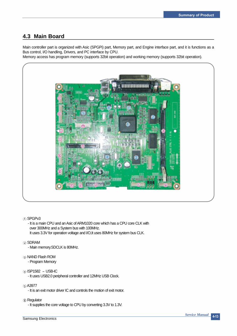
4.3 Main Board
Main controller part is organized with Asic (SPGPi) part, Memory part, and Engine interface part, and it is functions as aBus control, I/O handling, Drivers, and PC interface by CPU.Memory access has program memory (supports 32bit operation) and working memory (supports 32bit operation).
SPGPv3- It is a main CPU and an Asic of ARM1020 core which has a CPU core CLK withover 300MHz and a System bus with 100MHz.It uses 3.3V for operation voltage and I/O,It uses 80MHz for system bus CLK.
SDRAM- Main memory.SDCLK is 80MHz.
NAND Flash ROM- Program Memory
ISP1582 USB-IC - It uses USB2.0 peripheral controller and 12MHz USB Clock.
A3977- It is an exit motor driver IC and controls the motion of exit motor.
Regulator- It supplies the core voltage to CPU by converting 3.3V to 1.3V.

Service Manual
Summary of Product
4-14Samsung Electronics
EEPROM (24C04)- It is an EEPROM with 12C method,and it is used to DIMM and Option.
RAM--DIMM- When extending a RAM,connect the additional SDRAM B’ d.
Joint B’ d Connector- By connecting to Joint B’ d,it sends the operating signals of main/MP/Regi clutch and receives a cassette detect signal and aMP empty signal.If it is disconnected,it cannot detect such clutch operation and sensor.
Motor Connector- It is connected to a main BLDC motor,and it sends the motor control signal of CPU.If it is disconnected,a main motor does not operate.
Engine Connector- It connects a SMPS,supplies the power,and delivers the high voltage control signal,etc.If a harness is not normally connected to this connector,power cannot be supplied.
PTL connector- It connects to a PTL and helps to deliver the PTL On signal.
Cover Open connector- It detects the cover open.If it is disconnected,it cannot sense the cover on/off signal.
Main Fan connector- It drives a fan by connecting a main fan of a set.
LSU connector- It connects a LSU.
DC Motor connector- It connects an exit motor and drives a DC motor.
SMPS Fan connector- It connects a SMPS Fan.
Cart B d connector- It connects a toner cartridge and detects the cartridge information,the paper empty signal,and the paper regi signal.It connects the detecting signal of paper size,out-bin full,and thermistor.It could cause a fuser detecting error,a toner detecting error,and a paper detecting error when it is disconnected.
Panel connector- It is connected to a LCD panel.
Embedded Network Card connector- A place to connect the Embedded MAC Network card.
Shared Network Card connector- A place to connect the shared Network card.

Summary of Product
Service Manual 4-15Samsung Electronics
4.3.1 Controller
>> Video controller specificationThe video controller board is located on the right side of the printer.Basic Memory is 32 Mbytes SDRAM. Optional memory DIMMs are easily installed by following the simple instructions included in each option kit. Field upgradeable FLASH ROM firmware for controller
A.1 RAM DIMMs:Option SDRAM DIMM(Up to 128 Mbytes).
1) Printing ResolutionNative 600 x 600 dpi standard (PostScript 3,PCL6,PCL5e )Available 300 x 300 dpi (PostScript 3,PCL6,PCL5e)Resolution enhanced 1200 x 1200 dpi (PCL6,PostScript 3)Gray level:128 scale for 600 dpi,and 200 scale for 1200 dpi;PostScript 3,PCL6Toner Saver Mode In Toner Saver Mode,the toner savings is 50 %with acceptable print quality.
2) Micro Controller266MHz – 32 bit RISC Processor
3) Video Interface ControllerSPGPv3 Compatible Interface
4) Printer Language EmulationsPCL6 and PCL5e emulation with 45 scalable fonts from Bitstream,and 1 PCL bit-mapPostScript 3 emulation with 136 PS3 fonts from AGFA.Font Download UtilitySupport for DOS printing.Support for double byte printing (including Simplified and Traditional Chinese characters)Support for European currency symbol in PCL5e,PCL6 and PostScript Level 3(Detailed information on emulations is contained in the Eureka Controller Spec)
5) MemoryThe controller has 32 MB SDRAM and 32 MB NAND flash ROM on Board.1 DIMM expansion slots for SDRAM DIMMPackage:DIMM;100-pinType:SDRAMDIMM Type:Unbuffered (SEC Custom,support other products within SEC)Error Checking:Non-paritySpeed:100/133 MHzVoltage:3.3vSamsung proprietary design16/32/64/128MB
6) InterfacesThe system supports the following standard interfaces:
•One parallel port- (IEEE 1284 –1994 compliant,Bi-directional,ECP/Nibble/Byte Mode).
•One USB port- USB v.2.0 compliant
•One 10/100 BaseT NIC connector- The printer supports an internal Network Interface Card (NIC),which can be installed
pre-configured at the factory or as a customer installable option in thefield.This NIC supports all of the major Network Operating Systems such as the Novell NetWare,TCP/IP, etc. Details of the network specification will beprovided separately.
7) Control PanelRefer to the additional specification document This specification should address the hardware related to the front panel and buttons.The menu structure of the graphical UI will be addressed in the Controller Spec.

Service Manual
Summary of Product
4-16Samsung Electronics
4.3.2 Memory part
>> Flash Memory It stores the System Program.• Capacity: 2M Byte * 2• Access Time : 70 nsec
>>SDRAM It is used as Swath buffer, System working memory area, etc. when printing. • Capacity: 32M Byte (Basic), upto 160M Byte (Option)• DIMM : 16MB / 32MB / 64MB /128MB• Type : SDRAM 100MHz/133MHz , 16bit
>>ROM DIMMIt supports the option ROM DIMM 1 Slot for supporting the expanding Memory.• Capacity : 8MByte (Max)• Access Time : 70nsec
4.3.3 RESET CircuitAfter printer power is ON and 50~200 ms are passed, the reset signal from RESET IC (XC61FN3112MR) resets variousIC such as the CPU, Memory, etc. to prevent malfunction of the set by setting the initial value of port.
4.3.4 ClOCK CircuitBasically, it consists of the Crystal (12.5MHz) and Capacitor (27pF) which is connected to the crystal in parallel, and it is
inputted to the MCLLK_Signal via the CY25814. The purpose of the adding SY25814 is substitution of EMI.
4.3.5 INTERFACE Part
>>IEEE1284It supports the IEEE 1284 B Type Connection, and the protocol supports the IPP, ECP, Compatibility, Byte, and Nibblemode.
>>USB2.0USB2.0 Compliant, 480Mbps 1 port
>>Network• Option : Ethernet 10/100 Base TX• Protocol : SPX/IPX, TCP/IP,Appletalk, SNMP, HTTP 1.1, DLC/LLC
>>Panel• LCD : 16Char. * 2 Line / Back-light(Yellow)• Key : 9 Key• LED : 3 LEDThe UART method is used for the controller and panel interface, and the HR 48C50 Holtak Micom is used

Summary of Product
Service Manual 4-17Samsung Electronics
4.3.6 Sensor input circuit
4.3.6.1 Paper Empty SensingThe Paper empty sensor (Photo Interrupter) on the engine board informs the state of paper to LPEC1 whether it is emptyor not by operation of the actuator.When cassette is empty, it detects the fact by reading the GPIO3_1 of LPEC1, and then displays the fact on the LCD panel.
4.3.6.2 MP SensingBy operation of the MP Sensor (Photo Interrupter) on frame and Actuator, it informs the state of paper to CPU whether itis empty or not. It reads the IP5 sec_DRAM(K26) of CPU for recognizing paper in MP, and paper is fed from MP if thereis.
4.3.6.3 Paper Feeding When paper passes the actuator on the feed sensor part, it detects the signal of Photo interrupter, informs the paper feed-ing state to CPU, and then sprays the image data after certain time. If it doesn't detect the feed sensor within 1 sec. after paper is fed, paper jam0 (LPEC1 GPIO3_2) is occurred. (Displays onthe LCD panel)
4.3.6.4 Toner Remain SensingThe Toner cartridge terminal is mounted to the joint board located on frame. When the toner cartridge is inserted, it isadhered to the contacting point of the joint board to sense whether the toner cartridge exists or not, ID, amount of toner,and so on.
4.3.6.5 Paper Exit SensingIt detects paper state whether paper gets out from the set with operation of exit sensor on the engine board and actuatoron the frame. Paper detects the on/off time of exit sensor by reading LPEC1 GPIO3_6, and the normal operation or jaminformation is informed to the CPU.The paper JAM2 is informed. (Displays the state on LCD panel)
4.3.6.6 Cover Open SensingThe Cover open sensor is located on the front cover. After the front cover is opened, +24V and +5V (DC fan, solenoid,main motor, polygon motor part of LSU, HVPS, LSU Laser diode), which is supplied to each unit, is cut off.
4.3.6.7 DC FAN/Solenoid Driving CircuitA fan driving circuit is driven by a transistor and a controller which is in the LPEC.It is automatically turned off when a machine turns to sleep mode.There are two solenoids, and it is driven by an MP signal and a paper pick-up signal.
4.3.6.8 Motor Driving CircuitA main motor (BLDC) drives a feeding and developing unit and an exit motor (Step) drives a Fuser and anExit ass'y.When printing with a duplex function, it rotates the Exit Motor to a normal/reverse direction. It controls bydividing the acceleration section, standard speed section, and reducing speed section. A BLDC Motor isoperated by a clock and enable signal, and a Step Motor is managed with an A3977 driver IC.

Service Manual
Summary of Product
4-18Samsung Electronics
4.4 SMPS & HVPS board
The SMPS and HVPS are in one united board. The SMPS part supplies the DC power to the system.It takes either 110V or 220V and outputs the +3.3V and +24V to supply the power to the main board.The HVPS part creates the high voltage of THV/MHV/Supply/Dev and supplies it to the toner cartridge part for making thebest condition to display the image. The HVPS part takes the 24V and outputs the high voltage for THV/MHV/BIAS, and the outputted high voltage is suppliedto the toner, OPC cartridge, and transfer roller.
Exit Sensor
HVPS FuserMain PBA
Inlet

Summary of Product
Service Manual 4-19Samsung Electronics
4.4.1 HVPS(High Voltage Power Supply)
1) Transfer high voltage (THV (+))- Function: It is a voltage that transfers toner on an OPC Drum to paper.- Output voltage: MAX +4.2 KV +/- 5% (Duty is changeable, Not loading)- 1.7KV +/- 15% (When cleaning, 200MOhm - It transfers toners with (+) polarity of transfer roller to an OPC Drum.- Error type: IF THV (+) is not outputted, it causes a low density due to toner on an OPC Drum if it is not trans-
ferred to paper. It is possible that over-flow occurs if toner is piled up in a toner vessel continuously.
2) Charge voltage (MHV)- Function: It is a voltage that charges a surface of OPC to -750V~-900V. - Output voltage: -1.35KV~1.5KV DC +/- 50V- Error type: IF MHV is not outputted, toner overflows and reaches to an OPC drum if surface of an OPC is not
charged. A black paper is printed out when it happens.
3) Cleaning voltage: THV (-)- Function: It removes contamination at a rear by sending (-) polarity in a transfer roller to OPC drum to take toner.- Output voltage: A change range is large according to a load because there is no feedback control =(-600V~-
1200V)- Error type: An error due to contamination of toner on a backside of printing paper.
4) Developing voltage (DEV)- Function: It is a voltage that develops toner with electronic potential difference of the section exposed by LSU
(Laser Scanning Unit).* When printing, exposing voltage of OPC is -250V and exposing voltage of DEV is -470V. Therefore,
toner with (-) polarity is developed on an exposed section.- Output voltage: -380V~500DC +/- 20V- Error type: a) If DEV is GND, a density gets extremely low.
b) When DEV is floating due to instable of terminal’s contacting point, and etc., density getsextremely high.
5) Supplying voltage (SUP)- Function: It is a voltage that supplies toner to a developing roller.- Output voltage: -560V~680V DC +/- 50V (Use AENER, Gearing of DEV - (-)180V more than DEV) - Error type: a) When SUP is GND, density gets extremely low.
b) If SUP is floating due to instable of terminal’s contacting point, and etc., density gets extreme-ly low that it is hard to catch up with eyes.
6) OPC Ground ZENER voltage- Function: It is a voltage to prevent an image contamination under the condition of low temperature and low
humidity environment.- When a set prints without an output voltage, -100V is maintained on OPC ground. (-100V ZENER diode is con-
nected to OPC ground)- Error type: a) When ZENER diode is - 0V, there is no serious image problem in general environment, but
in low temperature and low humidity environment, it is possible that a contamination occuron entire image
b) When ZENER diode is disconnected, a blank page is printed out. (It is the same case aswhen a ZENER diode is disconnected to OPC ground.)
Service Manual
Summary of Product
4-20Samsung Electronics
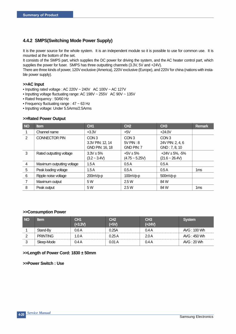
4.4.2 SMPS(Switching Mode Power Supply)
It is the power source for the whole system. It is an independent module so it is possible to use for common use. It ismounted at the bottom of the set.It consists of the SMPS part, which supplies the DC power for driving the system, and the AC heater control part, whichsupplies the power for fuser. SMPS has three outputting channels (3.3V, 5V and +24V).There are three kinds of power, 120V exclusive (America), 220V exclusive (Europe), and 220V for china (nations with insta-ble power supply).
>>AC Input• Inputting rated voltage : AC 220V ~ 240V AC 100V ~ AC 127V• Inputting voltage fluctuating range: AC 198V ~ 255V AC 90V ~ 135V• Rated frequency : 50/60 Hz• Frequency fluctuating range : 47 ~ 63 Hz• Inputting voltage: Under 5.5Arms/2.5Arms
>>Rated Power Output
>>Consumption Power
>>Length of Power Cord: 1830 ± 50mm
>>Power Switch : Use
NO Item CH1 CH2 CH3 Remark1 Channel name +3.3V +5V +24.0V
2 CONNECTOR PIN CON 3 CON 3 CON 33.3V PIN: 12, 14 5V PIN : 8 24V PIN: 2, 4, 6GND PIN: 16, 18 GND PIN: 7 GND : 7, 8, 10
3 Rated outputting voltage 3.3V ± 5% +5V ± 5% +24V ± 5%, -5%(3.2 ~ 3.4V) (4.75 ~ 5.25V) (21.6 ~ 26.4V)
4 Maximum outputting voltage 1.5 A 0.5 A 0.5 A
5 Peak loading voltage 1.5 A 0.5 A 0.5 A 1ms
6 Ripple noise voltage 200mVp-p 100mVp-p 500mVp-p
7 Maximum output 5 W 2.5 W 84 W
8 Peak output 5 W 2.5 W 84 W 1ms
NO Item CH1 CH2 CH3 System(+3.3V) (+5V) (+24V)
1 Stand-By 0.6 A 0.25A 0.4 A AVG : 100 Wh
2 PRINTING 1.0 A 0.25 A 2.0 A AVG : 450 Wh
3 Sleep-Mode 0.4 A 0.01 A 0.4 A AVG : 20 Wh

Summary of Product
Service Manual 4-21Samsung Electronics
>>Feature • Insulating resistance : over 50MΩ(at DC 500V) • Insulating revisiting pressure Must be no problem within 1min. (at 1500Vzc, 10mA)• Leaking voltage : under 3.5mA• Running voltage : under 50A peak (at 25°C, Cold start)Under 60A peak (in other conditions)• Rising Time : Within 2sec• Falling Time : over 20ms• Surge: Ring Wave 6KV-500A (Normal, Common)
>>Environment Condition• Operating temperature range : 0°C~50°C• Maintaining temperature range : -25°C~85°C• Maintaining humid range : 10% ~90% RH• Operating atmospheric pressure range: 1
>>EMI RequirementCISPR ,FCC, CE, MIC, C-Tick,
>>Safety Requirement IEC950 UL1950, CSA950, C-UL, TUV, Semko, iK, CB, CCC(CCIB),GOST, EPA
4.4.3 Fuser AC Power Control
Fuser (HEAT LAMP) gets heat by using AC power. The AC power controls the switch with the Triac, a semiconductorswitch. The 'On/Off control' is operated when the gate of the Triac is turned on/off by Photo triac, which is insulting part.In the other words, the AC control part is passive circuit, so it turns the heater on/off with taking signal from engine controlpart. When the 'HEATER ON' signal is turned on at engine, the LED of PC1 (Photo Triac) takes the voltage and flashes.From the flashing light, the Triac part (light receiving part) takes the voltage, and the voltage is supplied to the gate of Triacand flows into the Triac. As a result, the AC current flows in the heat lamp, and heat is occurred.On the other hand, when the signal is off, the PC1 is off, the voltage is cut off at the gate of Triac, the Triac becomes off,and then the heat lamp is turned off.
>>Triac (THY1) feature:12A,600V SWITCHING
>>Phototriac Coupler (PC3) • Turn On If Current : 16mA• High Repetive Peak Off State Voltage : Min 600V

Service Manual
Summary of Product
4-22Samsung Electronics
4.5 Engine F/W
4.5.1 Feeding
If feeding from a cassette, the drive of the pickup roller is controlled by controlling the solenoid. The on/off of the solenoidis controlled by controlling the general output port or the external output port. If feeding from a manual feeder, decide toinsert the paper according to the operation of the manual sensor, and by driving the main motor, insert the paper in frontof the feed sensor. While paper moves, occurrence of jam is judged as below. (Refer to the [6.2 Paper Transfer rout])
4.5.1.1 Jam 0• After picking up, paper cannot entered due to paper mis-feed.• After picking up, paper entered but it cannot reach to the feed sensor in certain time due to slip, etc.• After picking up, if the feed sensor is not on, repack up. After repacking up, if the feed sensor is not on
after certain time, it is Jam 0.- It is a status that the leading edge of the paper doesn’t pass the feed sensor.
• Even though the paper reaches to the feed sensor, the feed sensor doesn’t turn on.- It is a status that the leading edge of the paper already passed the feed sensor.
4.5.1.2 Jam 1• After the leading edge of the paper passes the feed sensor, the tailing edge of the paper cannot pass the
feed sensor after certain time. (The feed sensor cannot be Off)• After the leading edge of the paper passes the feed sensor, the paper cannot reach the exit sensor after
certain time. (The exit sensor cannot be On)- The paper exists between the feed sensor and the exit sensor.
4.5.1.3 Jam 2• After the tailing edge of the paper passes the feed sensor, the paper cannot pass the exit sensor after
certain time.
4.5.1.4 Duplex Jam 1A leading edge of a paper didn't reach a Duplex Sensor after certain time passes.
4.5.1.5 Duplex Jam 2After a leading edge of the paper passes the Duplex Sensor, the rear edge of the paper does not pass aDuplex Sensor within a certain time.
4.5.2 DriveA main motor (BLDC) drives a feeding and developing unit and an exit motor (Step) drives a Fuser and anExit ass'y.When printing with a duplex function, it rotates the Exit Motor to a normal/reverse direction. It controls bydividing the acceleration section, standard speed section, and reducing speed section. A BLDC Motor isoperated by a clock and enable signal, and a Step Motor is managed with an A3977 driver IC.
4.5.3 Transfer
The charging voltage, developing voltage and the transfer voltage are controller by PWM (Pulse WidthModulation). The each output voltage is changeable due to the PWM duty. The transfer voltage admittedwhen the paper passes the transfer roller is decided by environment recognition. The resistance value ofthe transfer roller is changed due to the surrounding environment or the environment of the set, and thevoltage value, which changes due to the environments, is changed through AD converter. The voltagevalue for impressing to the transfer roller is decided by the changed value.

Summary of Product
Service Manual 4-23Samsung Electronics
4.5.4 Fusing
The temperature change of the heat roller’s surface is changed to the resistance value through the thermistor. By con-verting the voltage value, which impressed to the resistance, to the digital value through the AD converter, the temperatureis decided. The AC power is controlled by comparing the target temperature to the value from the thermistor. If the valuefrom the thermistor is out of the controlling range while controlling the fusing, the error stated in the table occurs. (For thedomestic model, the Q-PID method has been applied.)
4.5.5 LSU
The LSU is consisted of the LD (Laser Diode) and the polygon motor control. When the printing signal occurs,it turns the LD and drives the polygon motor. When the receiving light part detects the beam, Hsync occurs.When the polygon motor speed becomes a normal, LReady occurs. If two conditions are satisfied, the sta-tus bit of the LSU controller register becomes 1 to be judged that the LSU is ready. If two conditions are notsatisfied, the error shown in below occurs.
Error Description LCD DisplayOpen Heat Error When warming up, it has been lower Engine Fuser Error
than 68°C over 28 seconds
Lower Heat Error • Standby: Engine Fuser Low Heat ErrorIt has been lower than 130°C over 10 seconds
• Printing: - 3 consecutive page; it has been 20°C lower than the fixed fusing temperature over 7 seconds.
Over Heat Error It have been higher than 230°C over 10 seconds Engine Fuser Over Heat Error
Error Description LCDPolygon motor error When the polygon motor’s speed doesn’t Engine LSUError
become a normal
Hsync error The polygon motor’s speed is normal, HSYNC Errorbut the Hsync signal is not created.
55
5-1Samsung Electronics
Disassembly and Reassembly
Service Manual
5. Disassembly and Reassembly
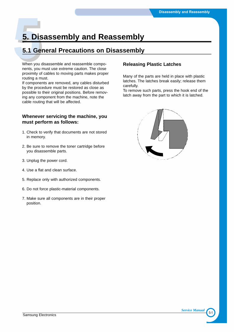
5.1 General Precautions on Disassembly
When you disassemble and reassemble compo-nents, you must use extreme caution. The closeproximity of cables to moving parts makes properrouting a must. If components are removed, any cables disturbedby the procedure must be restored as close aspossible to their original positions. Before remov-ing any component from the machine, note thecable routing that will be affected.
Whenever servicing the machine, youmust perform as follows:
1. Check to verify that documents are not storedin memory.
2. Be sure to remove the toner cartridge beforeyou disassemble parts.
3. Unplug the power cord.
4. Use a flat and clean surface.
5. Replace only with authorized components.
6. Do not force plastic-material components.
7. Make sure all components are in their properposition.
Releasing Plastic Latches
Many of the parts are held in place with plasticlatches. The latches break easily; release themcarefully. To remove such parts, press the hook end of thelatch away from the part to which it is latched.

5-2
Disassembly and Reassembly
Samsung ElectronicsService Manual
5.2 Transfer Roller
1. Open the Ope Cover. 2. Hold the lever at the both end of the roller, thenremove the roller.
Open Cover
Transfer RollerTransfer RollerTransfer Roller
Transfer Roller
Holder
<Cautions When Replacing a Transfer Roller>* Do not grab the transfer roller shown in picture (A). It may cause a malfunction due
to a foreign object.* Hold the both sides of the transfer roller shown in picture (B) when replacing it.
(A)
1. Open the Ope Cover. 2. Hold the lever at the both ends of the roller,then remove the roller.
(B)
5-3Samsung Electronics
Disassembly and Reassembly
Service Manual
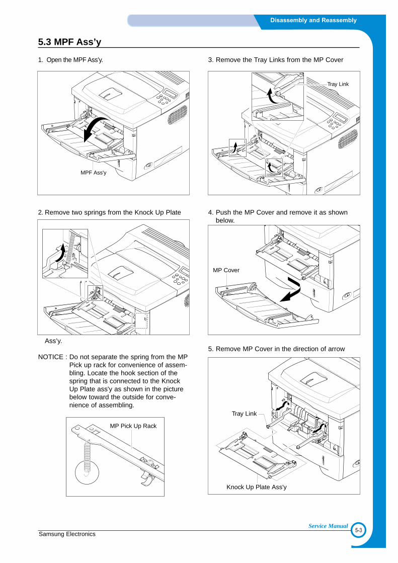
5.3 MPF Ass’y
1. Open the MPF Ass’y.
2. Remove two springs from the Knock Up Plate
Ass’y.
NOTICE : Do not separate the spring from the MPPick up rack for convenience of assem-bling. Locate the hook section of thespring that is connected to the KnockUp Plate ass'y as shown in the picturebelow toward the outside for conve-nience of assembling.
3. Remove the Tray Links from the MP Cover
4. Push the MP Cover and remove it as shownbelow.
5. Remove MP Cover in the direction of arrow
MPF Ass'y
Tray Link
MP Cover
MP Pick Up Rack
Knock Up Plate Ass'y
Tray Link

5-4
Disassembly and Reassembly
Samsung ElectronicsService Manual
5.4 Holder Pad Ass’y
1. Before you remove the Holder Pad Ass'y, you shouldremove:- MPF Ass’y (Refer to the 5.3)
2. Unplug the connector and remove the two screws, asshown below.
3. Remove the photo interrupter and the MP Actuatoras shown below.
Holder Pad Ass'y
MP Actuator
Photo Interrupter
5.5 RH Cover
1. Pull the Cassette out of the printer.
2. Remove two screws and take out the RH Cover.
Cassette
RH Cover

5-5Samsung Electronics
Disassembly and Reassembly
Service Manual
5.6 Control Board
1. Before you remove the Control Board Ass'y, youshould remove:- RH Cover (Refer to the 5.5)
2. Unplug the all connector, as shown below.
3. :The connectors are located as shown below.
4. Remove six screws and take out the ControlBoard.
5. Remove four screws and take out the ControlBoard Bracket.
NOTICE : One screw among the screws is lockedon the Engine Shield.(Refer to 5.25.3)
LSU
ExitMotor
Catridge
Key Panel
DC FanOpen Cover
DCU
Engine
PTL (REGI)
Maine Motor
Connector Board
Control Board
Control Board Bracket

5-6
Disassembly and Reassembly
Samsung ElectronicsService Manual
5.7 Main Drive Ass’y
1. Before you remove the RH Cover Ass'y, you shouldremove:- RH Cover (Refer to the 5.5)
2. Unplug the two connectors from the Main Boardand the Connector Board.
3. Remove the e-ring and take out the Clutch.
4.Remove six screws and take out the Main DriveAss’y.
5. When separating the Main Motor ass'y, discon-nect the connector form the Main PBA, remove4 screws, and then remove the Main Motorass'y.
Clutch
Main Drive Ass'y
Main Motor Ass'y

5-7Samsung Electronics
Disassembly and Reassembly
Service Manual
5.8 Connector Board
1. Before you remove the Connector Board, you shouldremove:- RH Cover (Refer to the 5.5)
2. Unplug all of the connectors from the ConnectorBoard and take it out.
3. The connectors are located as shown below.
Connector Board
MP Solenoid
Main Solenoid
Clutch
MP Empty
Control Board
5.9 Solenoid
1. Before you remove the Connector Board, you shouldremove:- RH Cover (Refer to the 5.5)
2. Unplug the MP Solenoid Harness and the MainSolenoid Harness from the Connector Board.
3. Remove two screws and take out the MPSolenoid.
4. Remove two screws and take out the MainSolenoid.
NOTICE : It is not necessary to disassemble theMain Drive Ass’y to remove the MPSolenoid
MP Solenoid
Main Solenoid

5-8
Disassembly and Reassembly
Samsung ElectronicsService Manual
5.10 LH Cover
1. Before you remove the LH Cover, you should remove:- Cassette (Refer to the 5.5)
2. Open the Rear Cover and remove two screws.
3.Remove two screws and take out the RH Cover.
Rear Cover
LH Cover
5-9Samsung Electronics
Disassembly and Reassembly
Service Manual
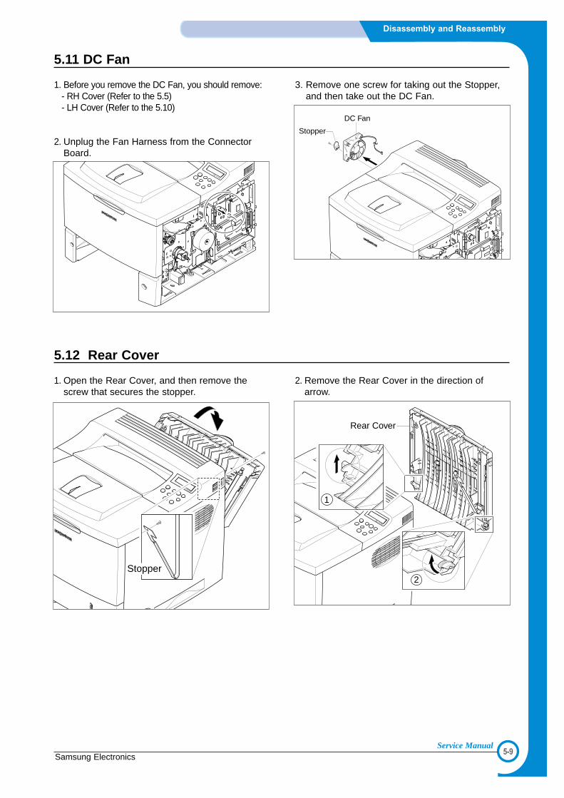
5.11 DC Fan
1. Before you remove the DC Fan, you should remove:- RH Cover (Refer to the 5.5)- LH Cover (Refer to the 5.10)
2. Unplug the Fan Harness from the ConnectorBoard.
3. Remove one screw for taking out the Stopper,and then take out the DC Fan.
DC Fan
Stopper
5.12 Rear Cover
1. Open the Rear Cover, and then remove thescrew that secures the stopper.
2. Remove the Rear Cover in the direction ofarrow.
Stopper
Rear Cover
1
2

5-10
Disassembly and Reassembly
Samsung ElectronicsService Manual
5.13 Top Cover
1. Before you remove the Top Cover, you shouldremove:- RH Cover (Refer to the 5.5)- LH Cover (Refer to the 5.10)
2. Open the MPF Ass’y, the Rear Cover, the OpenCover.
3. Unplug the two Connectors after you removethe three screws frome the Control Board.
4. Unlatch both ends of the Top Cover.
5.Unlatch the hook and take out the Top Cover.
6. Remove 7 screws, and then take out the LCDPanel and the Key Panel.
Top Cover
Key Panel
LCD PAnel
Key Panel
Cover Open

5-11Samsung Electronics
Disassembly and Reassembly
Service Manual
5.14 Open Cover
1. Before you remove the Open Cover, you shouldremove:- Top Cover (Refer to the 5.13)
2. Remove two screws and take out the Stopper.
3. Take out the Open Cover as shown below.
4. Release the lock as shown below and lift up theSensor Cap.
Stopper
Micro Switch PBA
Sensor Cap
Open Cover
5.15 Inner Cover
1. Before you remove the Inner Cover, you shouldremove:- MPF Ass/y (Refer to the 5.3) - Top Cover (Refer to the 5.13)
2. Remove two screws and take out the Inner Cover.
Inner Cover

5-12
Disassembly and Reassembly
Samsung ElectronicsService Manual
5.16 Fuser Ass’y
1. Before you remove the Fuser Ass’y, you shouldremove:- Rear Cover Refer to the 5.12)
2. Remove four screws and take out the FuserAss’y.
3. Remove two screws and take the Thermostatout of the Fuser Ass’y.
4. Remove one screw, and then take out theThermister from the Fuser Ass’y.
5. Remove two screws and take the HalogenLamp out of the Heat Roller.
6. Remove three screws and take out the Gearbracket.
7. Remove two screws and divide the Fuser intotwo parts.
Fuser Ass'y
Halogen Lamp
Gear Bracket
Fuser Upper Unit
Thermistor
Thermostat

5-13Samsung Electronics
Disassembly and Reassembly
Service Manual
8. Take out the Heat Roller as shown below. 9. Take out the Pressure Roller as shown below.
Heat Roller
Bushing
FuserGear
Pressure Roller
Bushing

5-14
Disassembly and Reassembly
Samsung ElectronicsService Manual
5.17 Exit Drive
1. Before you remove the Exit Driver, you shouldremove:- Top Cover (Refer to the 5.13)
2. Unplug the Exit Driver Harness from the ControlBoard.
3. Remove three screws and take out the ExitDriver Ass’y.
4.Remove two screws and take out the Exit Motor.
Exit Motor

5-15Samsung Electronics
Disassembly and Reassembly
Service Manual
5.18 Exit Roller
1. Before you remove the Exit Roller, you shouldremove:- Top Cover (Refer to the 5.13) - Exit Drive (Refer to the 5.17)
2. Remove the Exit Roller and Bearing as shownbelow.
3. Take out the Exit Gear as shown below.
4. Take out the Duplex Exit Roller as samemethod of the code
Bearing
Exit Roller
Duplex Exit Roller
Exit Gear
Bearing
5-16
Disassembly and Reassembly
Samsung ElectronicsService Manual
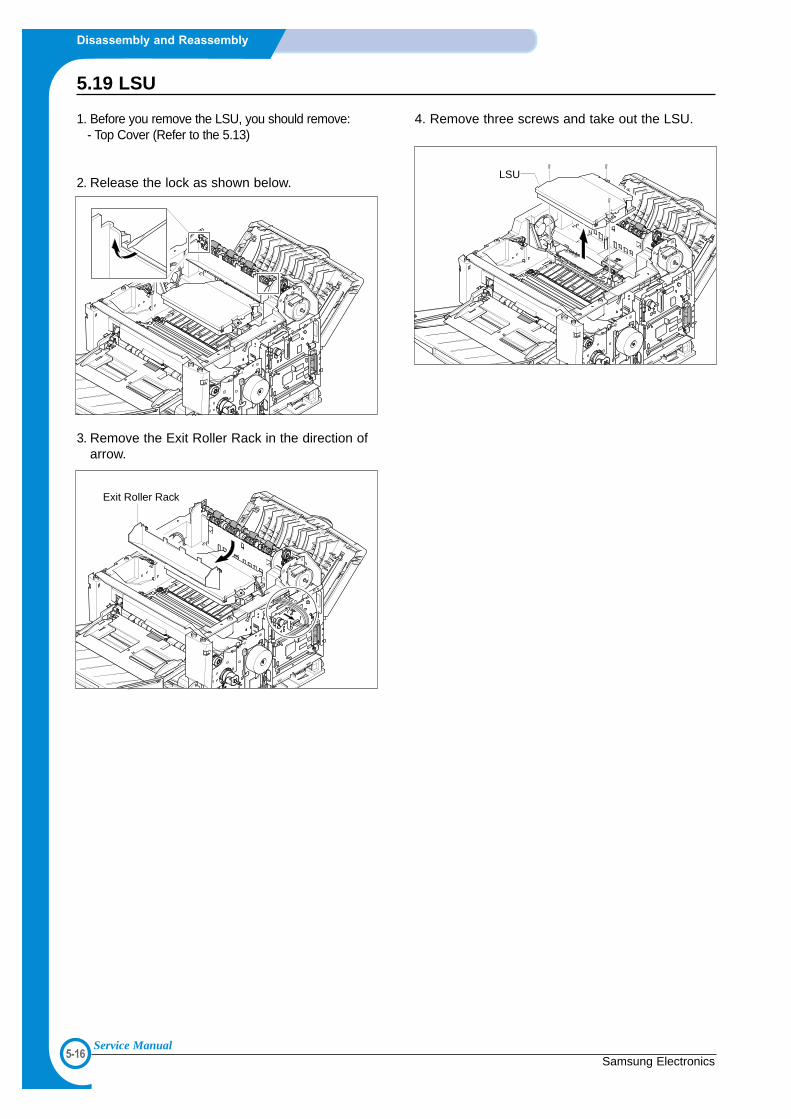
5.19 LSU
1. Before you remove the LSU, you should remove:- Top Cover (Refer to the 5.13)
2. Release the lock as shown below.
3. Remove the Exit Roller Rack in the direction ofarrow.
4. Remove three screws and take out the LSU.
LSU
Exit Roller Rack

5-17Samsung Electronics
Disassembly and Reassembly
Service Manual
5.20 Toner Sensor Board
1. Before you remove the Toner Sensor Board, youshould remove:- Top Cover (Refer to the 5.13) - LSU (Refer to the 5.19)
2. Unplug 4 Harness from the Toner Sensor Board.
3. Remove 4 screws and take out the TonerSensor Board.
4. Remove 3 screws and take out the LSU LowerCover.
LSU Lower Cover
HV SmallSpring
Toner Sensor Board

5-18
Disassembly and Reassembly
Samsung ElectronicsService Manual
5.21 REGI Ass’y
1. Before you remove the REGI Ass’y, you shouldremove:- Top Cover (Refer to the 5.13)
2. Unplug the Harness, Remove 3 screws.
3. Release the lock as shown below and lift up theGear Cap.
4. Take out the Regi. Ass’y as shown below.
5. Remove one screw and take out the Regi.Sensor.
6. Unplug the Harness, remove one screw andtake out the PTL PBA.
REGI Sensor
Sensor Holder
PTL PBA
PTL Upper
Gear Cap
REGI Ass'y

5-19Samsung Electronics
Disassembly and Reassembly
Service Manual
5.22 MP Pick Up Ass’y
1. Before you remove the MP Pick Up Ass’y, you shouldremove:- MPF Ass’y (Refer to the 5.3)- Main Drive Ass’y (Refer to the 5.7) - Top Cover (Refer to the 5.13) - Inner Cover (Refer to the 5.15)
2. First of all remove two screws. Lift up the MPPick Up Shaft for taking out the MP Pick UpRack.
3. Remove the E-Rings on both ends of GearAss’y and remove Ass’y as shown below.
4. Pull and remove the lock equipment, then rotatethe Bearing as shown below.
5. Slide the cam to the left by pulling on the MPPick-up shaft
MP Pick Up Rack
Rack
Bearing
CamMP Pick Up Shaft
Gear Ass'y
E-Ring

5-20
Disassembly and Reassembly
Samsung ElectronicsService Manual
6. First lift the left side of the Shaft and thenremove the Shaft.
7. Push the idles toward the ends of shaft thentake out the Housing as shown below.
1
2
Idle
Housing
1
2
1
Idle

5-21Samsung Electronics
Disassembly and Reassembly
Service Manual
5.23 Retard Ass’y
1. Before you remove the Retard Ass’y, you shouldremove:- MPF Ass’y (Refer to the 5.3) - Main Drive Ass’y (Refer to the 5.7) - Top Cover (Refer to the 5.13) - Inner Cover (Refer to the 5.15)
2. Remove two screws. Then lift the Roller Ass’y,as shown below.
3. Take out the Gear, as shown below.
4. Remove the lock equipment and rotate theBearing as shown below.
5. Slide the shaft (gear side) to the left side asshown in the picture. Next, left side of the sjaftto the right side. Be careful not to mass up withthe Holder Pad ass'y.
Roller Ass'y
1
2
Retard Gear
Bearing

5-22
Disassembly and Reassembly
Samsung ElectronicsService Manual
5.24 Pick Up Unit
1. Before you remove the Pick Up Unit, you shouldremove:- MPF Ass’y (Refer to the 5.3) - Main Drive Ass’y (Refer to the 5.7) - Top Cover (Refer to the5.13) - Inner Cover (Refer to the5.15)
2. Remove four screws. Then lift the Bottom CrossBar, as shown below.
3. Remove E-Ring and take The Gear Ass’y out.
4. Remove two springs from the Pick Up Ass’y.
5. Release the lock as shown below and lift up theStopper.
6. Lift ICU Shield out in the direction of arrow as shownbelow.
Bottom Cross Bar
Stopper
ICU Shield
Gear Ass'y

5-23Samsung Electronics
Disassembly and Reassembly
Service Manual
7. Remove the locking equipment rotate the FeedRoller and Pick Up Roller Shaft’s in the directionof the arrows and slide the bearings off asshown below.
8. Remove four screws and lift the Pick Up Unit out inthe direction of the arrow as shown below.
9. Remove the Feed Ass’y as shown below.
10. Remove the Pick Up Ass’y as shown below.
Pick Up Unit
Pick Up Roller
Feed Roller

5-24
Disassembly and Reassembly
Samsung ElectronicsService Manual
5.25 Engine Shield
1. Before you remove the Engine Shield, you shouldremove:- ICU Shield Refer to the 5.24)
2. Remove the Actuator as shown below.
Notice: Be careful not to get burnt when separat-ing an Engine PBA.
3. Remove ten screws and slightly lift the EngineShield, as shown below.
4. Unplug all of the connectors from the EngineBoard. Then take out the Engine Shield Ass’y.
Actuator
12
Engine Shield

5-25Samsung Electronics
Disassembly and Reassembly
Service Manual
5.26 Engine Board
1. Before you remove the Engine Board, you shouldremove:- Engine Shield (Refer to the 5.25)
2. Remove four screws and take the Engine Boardout of the Duplex Unit.
Engine Board
LH Guide(Duplex)
RH Guide(Duplex)

66
6-1Samsung Electronics
ALIGNMENT & ADJUSTMENTS
Service Manual
6. Alignment and Adjustments
This chapter describes the main functions for service, such as the product maintenancemethod, the test output related to maintenance and repair, DCU using method, Jam removingmethod, and so on. It includes the contents of manual.
6.1 How to use EDC (Engine Diagnostic Control) Mode
6.1.1 EDC Setup
• EDC(Engine Diagnostic Control, EDC will be used below) is considered to test and check whether each functions ofmachinery and h/w module are normal or not. All of the test function are able to be controlled by the keys and LCDwindow on the panel without any other kits.
• It’s developed for related engineers, not for users.
6.1.2 Entering/Exiting Method For EDC
<1> Outline• The method for entering “EDC” mode is especial because it is intended for technicians and not users• After Entering the mode, the message, “Engine EDC Mode” is displayed.• On the mode, an engineer should press the “Menu Key” to search each function he would like to test.• Turn the power off, after the test is entirely end.
<2> Usage1. Power off the printer.2. Pressing the “Select key”, power the printer on.3. Keep pressing it until the message, “Engine EDC Mode” is shown on the panel.4. Follow the usage for a function you would like to use.5. Turn the power off, after the test is complete.
6.1.3 Usage & Function of Key on OPE
6.1.4 Usage & Function of LCD
Key Function Description Remarks
Menu Menu To enter the main Menu
Arrow (right) Search a Menu/ Input Data To search a Menu and input a data
Arrow (left) Search a Menu/ Input Data To search a Menu and input a data
Select Execute / Select To execute a function
Cancel Stop / Cancel To stop a function
Upper Level Move To move to the upper level
Line Characters Description Remarks
Top 16 Make engineers recognizing a test location.
[Main Menu] or [Function] is displayed.
Bottom 16 Make engineers recognizing a menu or function to be tested
A menu or function name displayed

6-2
ALIGNMENT & ADJUSTMENTS
Samsung ElectronicsService Manual
6.1.2 How to use EDC (Engine Diagnostic Control) Mode
Tray3 Interface
Interface Test
Pattern Print
Setting Temperature TestLaser Diode TestLaser Ready Test
Dev Bias Test Charge Roll Voltage Transfer Positive Voltage Transfer Negative VoltagePTL Test
Main Motor Laser Motor Duplex Forward Duplex Reverse Tray3 Motor Fan Test
Tray1 Sensor Tray2 SensorTray3 Sensor Duplex Sensor Cover Open SensorFeed SensorExit Sensor
Solenoid Test
Motor/Fan Test
Sensor TestHVPS Test
Development Test
Test Pattern Print
Tray1 Solenoid Test Tray2 Solenoid Test Tray3 Solenoid Test Tray2 Clutch Test Tray3 Clutch Test

6-3Samsung Electronics
ALIGNMENT & ADJUSTMENTS
Service Manual
6.1.2.1 Interface Test (Main controller and Tray3 controller)
- This Function is used to check the communication state between the main controller and the tray3 controller.
1. Press the "Menu Key", until finding "Interface Test" message on the panel.2. Press the "Select Key", when it's found.
Sub Menu Description Display (LCD)
Tray3 Interface After it is on the test, confirm a message on the panel. Tray 2 I/F : PASS(FAIL)
The I/F is normal for the message, "PASS" and
abnormal for the message, "FAIL" on the bottom line.
6.1.2.2 Test Pattern and Paper path
- These Functions are considered to check the total print process state.- On the EDC mode, a Test pattern is able to be printed. While the printing job is processing, the
location of the paper is continuously displayed.
1. Press the “Menu Key” until finding “Test Pattern Print” message on the panel.2. Press the “Select Key”, when it’s found.3. Confirm the message “Choose a tray: 1”(default: 1).4. Press the “Arrow keys” (< / >) to select a tray you would like to choose.5. Fill a Tray(1, 2, 3) with papers.5. Press the “Select Key”, if you would like to print it.
Location order: Pick up a Feed On → Exit On → Feed Off → Exit Off → End(It is possible that Feed Off → Exit On, when a paper size is small)
Sub Menu Description Display (LCD) Remark
Test Pattern Print The test pattern is printed after the execution Pattern Print Example ->
key is chosen and “More?” is displayed. (Location) Pattern Print
Press the “Select Key” for printing more, : Exit On
the “Cancel Key” for stopping.

6-4
ALIGNMENT & ADJUSTMENTS
Samsung ElectronicsService Manual
6.1.2.3 Motor & Fan Test
- These Functions are used to check the present state (normal or not) of the motors and fan.
1. Press the "Menu Key", until finding "Motor/Fan Test" is displayed on the panel.2. Press the "Select Key", when it's found.3. Press the "Arrow keys" (< / >), until finding the desired function
(Refer to the table below).4. Press the "Select Key", when it's found.5. Press the "Select Key" for execution or the "Cancel key" to stop.
Sub Menu Description Remarks
Main Motor The main motor keeps running after the execution key Main Motor On(Off)
is chosen and stops when the stop key is chosen.
Laser Motor The laser motor keeps running after the execution key Laser Motor On(Off)
is chosen and stops when the stop key is chosen.
Duplex Duplex Forward The duplex motor keeps running on the forward direction Duplex Forward On(Off)
Motor after the execution key is chosen and stops when
the stop key is chosen.
Duplex Reverse The duplex motor keeps running on the backward direction Duplex Backward On(Off)
after the execution key is chosen and stops when
stop key is chosen.
Tray3 Motor The Tray3 motor keeps running after the execution key Tray 3 Motor On(Off)
is chosen and stops when the stop key is chosen.
--> When a tray 3 is not installed, this function is not
processed and "Tray 3 Not Installed" is shown.
FAN The fan keeps running after the execution key is chosen Fan On(Off)
and stops when the stop key is chosen.

6-5Samsung Electronics
ALIGNMENT & ADJUSTMENTS
Service Manual
6.1.2.4 Solenoid & Clutch Test
- These Functions are used to check the present state (normal or not) of the solenoids and clutches.
1. Press the "Menu Key", until finding "Solenoid Test" is displayed on the panel.2. Press the "Select Key", when it's found.3. Press the "Arrow keys" (< / >), until finding the desired function.
(Refer to the table below)4. Press the "Cancel Key", when it's found.5. Press the "Select Key" for execution
Sub Menu Description Remarks
Tray1 Solenoid Test The tray1 solenoid is on for 150ms and then it automatically stops, Tray 1 Solenoid On/Off
when the execution is chosen.
Tray2 Solenoid Test The tray2 solenoid is on for 150ms and then it automatically stops, Tray 2 Solenoid On/Off
when the execution is chosen.
Tray3 Solenoid Test The tray3 solenoid is on for 150ms and then it automatically stops, Tray 3 Solenoid On/Off
when the execution is chosen.
Tray2 Clutch Test The tray2 clutch is on for 1sec and then it automatically stops, Tray 2 Clutch On/Off
when the execution is chosen.
On this function, the main motor runs before 2sec from the point
of the clutch on in order to check the clutch state.
Tray3 Clutch Test The tray3 clutch is on for 1sec and then it automatically stops, Tray 3 Clutch On/Of
when the execution is chosen.
On this mode, the tray 3 motor runs before 2sec from the point
of the clutch on in order to check the clutch state.
--> When a tray 3 is not installed, this function is not processed
and "Tray 3 Not Installed" is shown.

6-6
ALIGNMENT & ADJUSTMENTS
Samsung ElectronicsService Manual
6.1.2.5 Sensor Test
- These Functions are considered to check the present state (normal or not) of the Sensors.
1. Press the "Menu Key", until finding "Sensors Test" message on the panel.2. Press the "Select Key", when it's found.3. Press the "Arrow keys" (< / >), until finding a suitable function.4. Press the "Select Key", when it's found.3. Touch a sensor you would like to test.4. Confirm a message on the LCD window for the state of it.
Sub Menu Description Display(LCD)
Befor touching After touching
Tray1 Sensor After the tray 1 is gotten down, touch the sensor Tray 1 Sensor Off Tray 1 Sensor Oo
and confirm the message changed "Tray 1 Sensor Off"
to "Tray 1 Sensor On"
Tray2 Sensor After the tray 2 is pulled out, touch the sensor Tray 2 Sensor Off Tray 2 Sensor On
and confirm the message changed "Tray 2 Sensor Off"
to "Tray 2 Sensor On".
Tray3 Sensor After the tray 3 is pulled out, touch the sensor Tray 3 Sensor Off Tray 3 Sensor On
and confirm the message changed "Tray 3 Sensor Off"
to "Tray 3 Sensor On".
Duplex Sensor After the back cover is open, push a paper into the Duplex Sensor Off Duplex Sensor On
duplex path and confirm the message changed
"Duplex Sensor Off" to "Duplex Sensor On".
Cover Open After the cover is open, touch the sensor and confirm Cover Open Cover Close
Sensor the message changed "Cover Open" to " Cover Close"
Feed Sensor Touch the Feed sensor. Feed Off Feed On
Exit Sensor Touch the Feed sensor. Exit Off Exit On

6-7Samsung Electronics
ALIGNMENT & ADJUSTMENTS
Service Manual
6.1.2.6 HVPS Test Item : High Voltage Power Supply
- These Functions are used to check whether the control for HVPS is normal or not.
1. Press the "Menu Key", until finding "Developing Test" is displayed on the panel.2. Press the "Select Key", when it's found.3. Press the "Arrow keys" (< / >), until finding a suitable function
(Refer to the table below).4. Press the "Select Key", when it's found.5. Press the "Select Key" for execution or the "Cancel key" for stop.
Sub Menu Description Display (LCD) Remarks
Dev Bias Test Dev bias(- 470V) and Supply bias(- 650V) are Dev Bias On (Off)
supplied and after the execution key is chosen
and it stops when the stop key is chosen.
Charge Roll Charge roll voltage (- 1500V) is supplied after Charge: -1500V [Value] ADC value
Voltage Test the execution key is chosen and it stops when displayed
the stop key is chosen.
Transfer (+) Test Transfer positive voltage (+1000V) is supplied after Transfer: +1000V [Value ADC value
the execution key is chosen and it stops when displayed
the stop key is chosen.
Transfer (-) Test Transfer negative voltage(- 600 ~ -1000 V) is Transfer(-) On(Off) Voltage in
supplied after the execution key is chosen and it the range
stops when the stop key is chosen.
PTL Test PTL(Pre-Transfer Lamp) is on after the execution PTL On(Off)
key is chosen and it stops when the stop key
is chosen.
6.1.2.7 Developing Test Item : Fuser,Laser Scanning Unit
- These Functions are used to check whether functions related to the development are normal or not. (Fuser,OPC, LSU)
1. Press the "Menu Key", until finding "Developing Test" is displayed on the panel.2. Press the "Select Key", when it's found.3. Press the "arrow keys" (< / >), until finding a suitable function
(Refer to the table below).4. Press the "Select Key", when it's found.5. Press the "Select Key" for execution or the "Cancel key" for stop.
Sub Menu Description Display (LCD) Remarks
Setting Temperature When “Temp” is displayed, Input a temperature [Temperature]: Test T:[target value]
you would like to set with the “arrow keys( )”. C:[current value]
It will be displayed on the bottom line. on/off
Laser Diode Test “Diode On” is displayed, when the laser diode is on. Ld On(Off)
On the other case “Diode Off” is displayed.
Laser Ready Test “Laser Leady” is displayed, When the Laser Laser Leady (Error)
Scanning Unit is ready to print. On the other case
“Laser Error”

6-8
ALIGNMENT & ADJUSTMENTS
Samsung ElectronicsService Manual
6.2 Paper Path
LSU
솔레노이드솔레노이드
Toner CartridgeToner Cartridge
MPFFuserFuser
LSUToner Cartridge
MPFFuser
R1R1R1
S1
S2
S3
S4
S5
R9R9R9
R3R10R10R10
R1R11R11
R12R12R12
R2R2R2R3R3
R4R4
R3
R4 R5R5R5
R6R6R6R7R7R7R8R8R8
R1 : OPC Drum R7 : Feed Roller S1: Paper Empty(Cassette) Sensor
R2 : Transfer Roller R8 : Pick-UP Roller S2: Paper Empty(MPF) Sensor
R3 : Regi Roller R9 : Heat Roller S3: Regi Sensor
R4 : Idle Roller R10 : Pressure Roller S4: Exit SensorR5 : MP Pick-UP Roller R11 : Duplex Roller S5: Duplex Sensor
R6 : Retard Roller R12 : Duplex Idle Roller
<Jam 0> <Jam 1>

6-9Samsung Electronics
ALIGNMENT & ADJUSTMENTS
Service Manual
• Simplex1) A paper is fed from a cassette or MPF by a printing order.2) The fed paper passes a paper feeding sensor.
- If the sensor does not operate after feeding the paper, the Jam0 occurs. 3) The paper passes a paper exit sensor, and it comes out from a machine.
- If the tailing edge of the paper does not come out from a machine after the leading edgeof the paper passes the sensor, then certain time later, a Jam2 occurs.
• Duplex1) A paper is fad from a cassette or MPF by a printing order.2) The fed paper passes a paper feeding sensor.
- If the sensor does not operate after feeding the paper, a Jam0 occurs. 3) The paper that passes a paper exit sensor takes several printing processes, and moves to a
paper exit sensor.- If the sensor does not operate after certain time, a Jam 1 occurs.
4) If the paper does not discharge until the paper passes an exit roller and a Roller-Exit-F/Down, aJam 2 occurs.
5) The printing paper starts to be printed for duplex only by reversing rotation by an exit motor. Theprinting paper enters to a machine through an exit roller, and reaches to duplex sensor.
- If the printing paper cannot reach to the duplex sensor after certain time, a duplex Jam 1occurs.
6) The printing paper that passes the duplex sensor reaches to a feed sensor again and a printingoperation is tried over again.
- If the printing paper cannot reach to a feed sensor after certain time later, a duplex Jam 2occurs.
<Jam 2>
<Jam Duplex 1> <Jam Duplex 2>
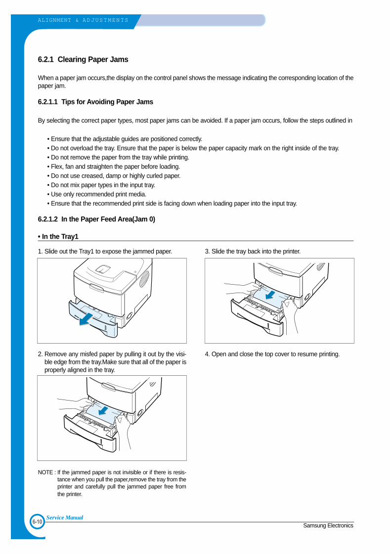
6-10
ALIGNMENT & ADJUSTMENTS
Samsung ElectronicsService Manual
6.2.1 Clearing Paper Jams
When a paper jam occurs,the display on the control panel shows the message indicating the corresponding location of thepaper jam.
6.2.1.1 Tips for Avoiding Paper Jams
By selecting the correct paper types, most paper jams can be avoided. If a paper jam occurs, follow the steps outlined in
• Ensure that the adjustable guides are positioned correctly.• Do not overload the tray. Ensure that the paper is below the paper capacity mark on the right inside of the tray.• Do not remove the paper from the tray while printing.• Flex, fan and straighten the paper before loading. • Do not use creased, damp or highly curled paper.• Do not mix paper types in the input tray.• Use only recommended print media.• Ensure that the recommended print side is facing down when loading paper into the input tray.
6.2.1.2 In the Paper Feed Area(Jam 0)
• In the Tray1
1. Slide out the Tray1 to expose the jammed paper.
2. Remove any misfed paper by pulling it out by the visi-ble edge from the tray.Make sure that all of the paper isproperly aligned in the tray.
NOTE : If the jammed paper is not invisible or if there is resis-tance when you pull the paper,remove the tray from theprinter and carefully pull the jammed paper free fromthe printer.
3. Slide the tray back into the printer.
4. Open and close the top cover to resume printing.

6-11Samsung Electronics
ALIGNMENT & ADJUSTMENTS
Service Manual
• In the Optional Tray2
1. Pull the optional Tray2 out of the printer.
2. If you see the jammed paper,remove the paper fromthe tray.
3. If you cannot find the jammed paper in the Tray2,pullthe Tray1 half way out of the printer,and remove thepaper.
4. Slide the trays back into the printer. Open and close thetop cover.Printing can be resumed.
• In the Multi-Purpose Tray
1. Open the Multi-Purpose Tray.
2. Carefully remove the jammed paper from the tray.
3. Open and close the top cover.Printing can be resumed.

6-12
ALIGNMENT & ADJUSTMENTS
Samsung ElectronicsService Manual
6.2.1.3 Around the Toner Cartridge (Jam1)
1. Open and close the top cover,and the jammed papershould exit the printer.
If not,continue to Step 2.
2. Open the top cover and remove the toner cartridge.
CAUTION : To prevent damage to the toner cartridge,do notexpose it to light for more than a few minutes.Placea piece of paper over the top of the toner cartridgeto shield it while it is out of the printer.
3. Carefully lift up the guide feed.
4. Gently pull the jammed paper towards you to remove itfrom the printer.
If the jammed paper is not visible or there is resistancewhen you pull the paper,go to “In the Paper Exit Area ”.
5. Flip down the guide feed and reinstall the toner car-tridge.
NOTE : If the toner cartridge is difficult to reinstall,make surethat the guide feed has been flipped back down intoposition.
6. Close the top cover.Printing can be resumed.
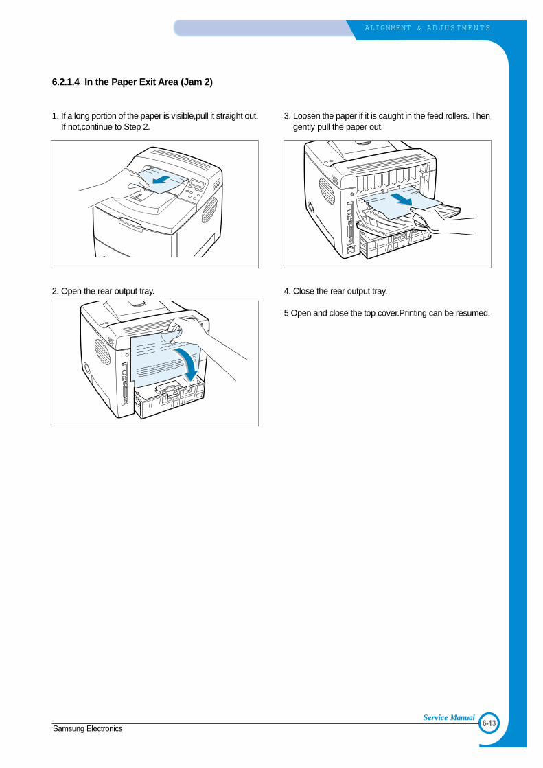
6-13Samsung Electronics
ALIGNMENT & ADJUSTMENTS
Service Manual
6.2.1.4 In the Paper Exit Area (Jam 2)
1. If a long portion of the paper is visible,pull it straight out.If not,continue to Step 2.
2. Open the rear output tray.
3. Loosen the paper if it is caught in the feed rollers. Thengently pull the paper out.
4. Close the rear output tray.
5 Open and close the top cover.Printing can be resumed.

6-14
ALIGNMENT & ADJUSTMENTS
Samsung ElectronicsService Manual
6.2.1.5 In the Duplex Area
• Duplex Jam 1
1. Open the rear output tray.
2. Remove the jammed paper.
3. Close the rear output cover.
4. Open and close the top cover.Printing can be resumed.
• Duplex Jam 2
1. Pull the paper tray out of the printer.
2. Pull down the metal plate inside of the printer.
CAUTION : Pulling the plate could cause an injury.Use the leveron the left.
3. Remove the jammed paper.
4. Slide the tray back into the printer.
5. Open and close the top cover.Printing can be resumed.

6-15Samsung Electronics
ALIGNMENT & ADJUSTMENTS
Service Manual
6.3 Sample Pattern
This product has the several sample patterns for maintenance. With the sample patterns, check the existence of the abnor-mality. The patterns help to regularly maintain the product.
6.3.1 Printing a Demo PagePrint a demo page to make sure that the printer is operating correctly.
1. Press the Menu button on the control panel until you see “Information ” on the bottom line of the display..
2. Press the Enter button to access the Menu.
3. Press the scroll button until you see “Demo Page ” on the bottom line.
4. Press the Enter button .
A demo page showing the printer ’s features and capabilities prints out.
6.3.2 Printing a cleaning sheetIf you are experiencing blurred,faded or smeared printouts,you can clear the problem by printing a cleaning sheet,provid-ed by your printer.You can print:
• OPC Cleaning sheet:cleans the OPC drum of the toner cartridge.• Fuser Cleaning sheet:cleans the fuser unit inside the printer.
This process will produce a page with toner debris,which should be discarded.
1. Ensure that the printer is turned on and in ready mode with paper loaded in the tray.
2. Press the Menu button on the control panel until you see “Setup ” on the bottom line of the display..
3. Press the Enter button to access the Menu.
4. Press the scroll button until “Maintenance ” displays on the bottom line and press the Enter button .
5. Press the scroll button to select the required option,“OPC Cleaning ” or “Fuser Cleaning.”
6. Press the Enter button .
Your printer automatically picks up a sheet of paper from the tray and prints out a cleaning sheet with dust or tonerparticles on it.

6-16
ALIGNMENT & ADJUSTMENTS
Samsung ElectronicsService Manual
6.3.3 Checking the toner cartridge count
Information about the 'toner cartridge count' can be checked by printing the Configuration Sheet.
6.3.3.1 Remaining Toner: xx%- Contents: Shows the remaining amount of toner.- Description: It starts with 100%, and it reduces every 5% unit until it becomes 0%. (A message "Low
Toner" is displayed in a LCD when it reaches 10%.)* In a low toner status, additional 800 sheets can be printed (5% coverage pattern standard-8K car-
tridge)
6.3.3.2 OPC Count: XXXXXX- Contents: It starts with 0 and increases to display count.- Description: It is an imaginary page count that accumulates a rotating time of a Main Motor. When the
count reaches 20,000(pages), a message "Replace cart" is displayed in LCD. It meansthe life span of the toner cartridge (except a toner part) has ended. Even though it is acase that a toner is refilled, the rest of major parts should end, so entire toner cartridgeshould be replaced. In the worst case, when an OPC rotates over 20,000 pages, it is pos-sible that a toner may overflow. When the count reaches to 20,000 pages, the printedimage becomes misty, and an On-Line key that is flashing on a set must be pressed for asingle print. If an OPC count is under 8,000 when displaying a message "RemainingToner:0%", it means that a high-coverage has been used. If an OPC count is over 8,000and if it has not been reached to 0% yet, a low-coverage should was used.
6.3.3.3 Manufacture Date: 2003.01- Contents: Shows the product year and the month of the developer.
6.3.3.4 Supplier: SAMSUNG- Contents: shows the brand name of the developer. (Supplier is Samsung)- Description: If a supplier is other OEM, the other OEM's name is displayed. If a supplier is different
between a set and developer, a message "invalid toner" will be displayed in a LCD of a set,and a machine turns to an impossible status to print.

6-17Samsung Electronics
ALIGNMENT & ADJUSTMENTS
Service Manual
6.3.3.5 A checking method of a toner remaining amount(1) Check a configuration sheet.(2) Check by using a key of a set. (Setup-maintenance-remain toner)(3) Check with a network: Check on a Webthru (Setup Menu-remaining toner)
Jumper
Caution(1) Please be careful not to damage atoner sensor part when assembling anddisassembling a developer.(2) Please be careful not to stain any-thing to jumper (4), which is shown in thepicture.

6-18
ALIGNMENT & ADJUSTMENTS
Samsung ElectronicsService Manual
COMPONENT REPLACEMENT CYCLE
Pick-up Roller 100,000 Pages
Paper Feeding Roller(Friction Pad) 100,000 Pages
Transfer Roller 100,000 Pages
Fuser 100,000 Pages
Toner Cartridge Normal cartridge : 8,000 Pages (A4 5% Pattern)
Starter cartridge : 4,000 Pages (A4 5% Pattern)
6.4 Consumables and Replacement Parts
The cycle period outlined below is a general guideline for maintenance. The example list is for an average usage of 50 transmitted and received documents per day. Environmental conditions and actual use will vary these factors. The cycle period given below is for reference only.
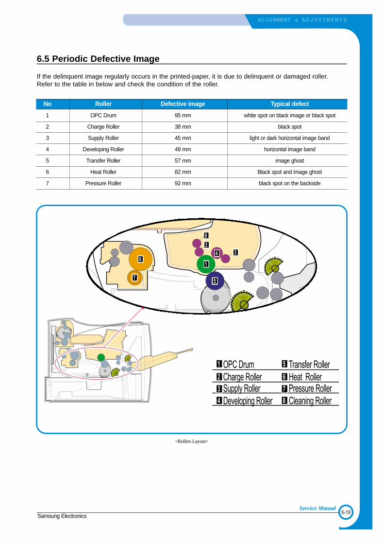
6-19Samsung Electronics
ALIGNMENT & ADJUSTMENTS
Service Manual
6.5 Periodic Defective Image
If the delinquent image regularly occurs in the printed-paper, it is due to delinquent or damaged roller.Refer to the table in below and check the condition of the roller.
No Roller Defective image Typical defect
1 OPC Drum 95 mm white spot on black image or black spot
2 Charge Roller 38 mm black spot
3 Supply Roller 45 mm light or dark horizontal image band
4 Developing Roller 49 mm horizontal image band
5 Transfer Roller 57 mm image ghost
6 Heat Roller 82 mm Black spot and image ghost
7 Pressure Roller 92 mm black spot on the backside
솔레노이드솔레노이드
R1R11
R12R12
OPC DrumCharge RollerSupply RollerDeveloping Roller
Transfer RollerHeat RollerPressure RollerCleaning Roller
1
2
3
4
1
8
34
5
6
7
2
5
6
7
8
<Rollers Layout>

6-20
ALIGNMENT & ADJUSTMENTS
Samsung ElectronicsService Manual
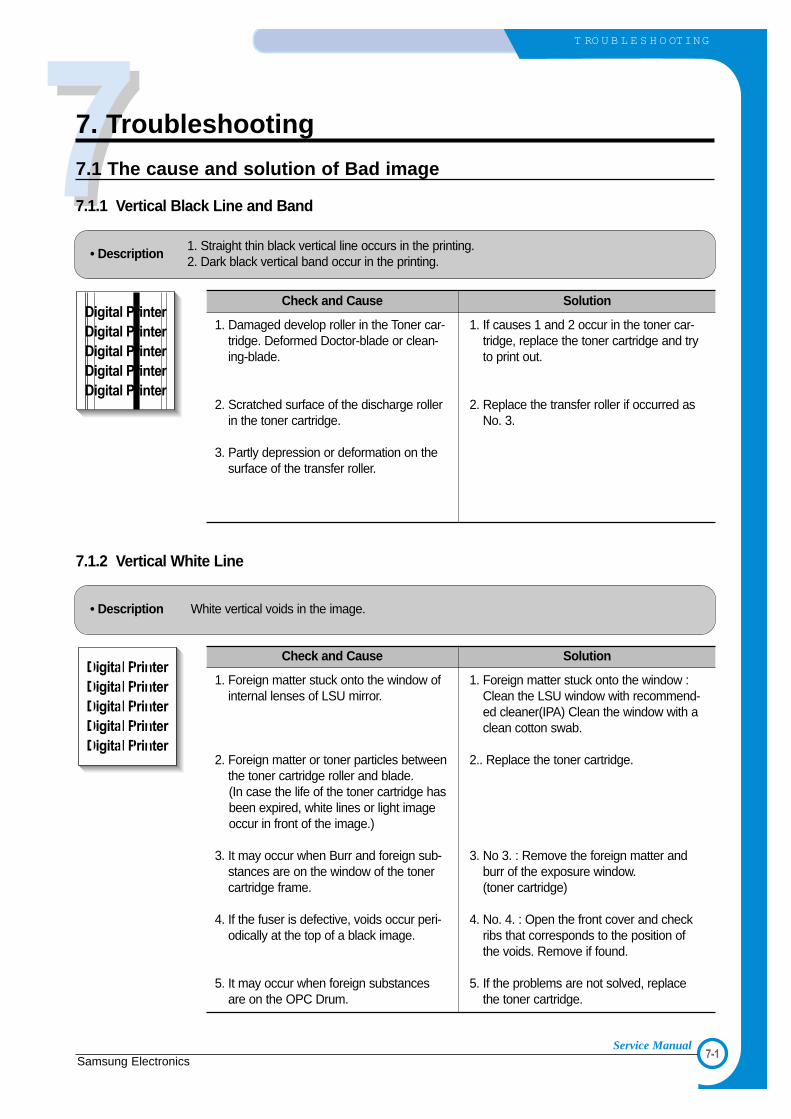
77
7-1Samsung Electronics
T RO U B L E S H O OTING
Service Manual
7. Troubleshooting
7.1 The cause and solution of Bad image
7.1.1 Vertical Black Line and Band
• Description1. Straight thin black vertical line occurs in the printing.2. Dark black vertical band occur in the printing.
Digital PrinterDigital PrinterDigital PrinterDigital PrinterDigital Printer
Check and Cause Solution
1. Damaged develop roller in the Toner car-tridge. Deformed Doctor-blade or clean-ing-blade.
2. Scratched surface of the discharge rollerin the toner cartridge.
3. Partly depression or deformation on thesurface of the transfer roller.
1. If causes 1 and 2 occur in the toner car-tridge, replace the toner cartridge and tryto print out.
2. Replace the transfer roller if occurred asNo. 3.
7.1.2 Vertical White Line
• Description White vertical voids in the image.
Digital PrinterDigital PrinterDigital PrinterDigital PrinterDigital Printer
Check and Cause Solution
1. Foreign matter stuck onto the window ofinternal lenses of LSU mirror.
2. Foreign matter or toner particles betweenthe toner cartridge roller and blade.(In case the life of the toner cartridge hasbeen expired, white lines or light imageoccur in front of the image.)
3. It may occur when Burr and foreign sub-stances are on the window of the tonercartridge frame.
4. If the fuser is defective, voids occur peri-odically at the top of a black image.
5. It may occur when foreign substancesare on the OPC Drum.
1. Foreign matter stuck onto the window :Clean the LSU window with recommend-ed cleaner(IPA) Clean the window with aclean cotton swab.
2.. Replace the toner cartridge.
3. No 3. : Remove the foreign matter andburr of the exposure window.(toner cartridge)
4. No. 4. : Open the front cover and checkribs that corresponds to the position ofthe voids. Remove if found.
5. If the problems are not solved, replacethe toner cartridge.

7-2
T RO U B L E S H O OTING
Samsung ElectronicsService Manual
7.1.3 Horizontal Black Band
• Description1. Dark or blurry horizontal stripes occur in the printing periodically.
(They may not occur periodically.)
Digital PrinterDigital PrinterDigital PrinterDigital PrinterDigital Printer
Check and Cause Solution
1. Bad contacts of the voltage terminals totoner cartridge.
2. The rollers of toner cartridge may bestained.
Charge roller = 38mmSupply roller = 45mmDevelop roller = 49mmTransfer roller = 57mm
1. Clean each voltage terminal of the Charge,Supply, Develop and Transfer roller.(remove the toner particles and paper par-ticles)
2. Clean the left Gear that has relativelysmall gap of the teeth in the OPC.
3. If the malfunction persists, replace thetoner cartridge.
7.1.4 Black/White Spot
• Description1. Dark or blurry black spots occur periodically in the printing.2. White spots occur periodically in the printing.
Digital PrinterDigital PrinterDigital PrinterDigital PrinterDigital Printer
Check and Cause Solution
1. If dark or blurry black spots occur periodi-cally, the rollers in the Toner cartridgemay be contaminated with foreign matteor paper particles.( Charge roller : 38 mm intervalOPC drum : 95 mm interval)
2. If faded areas or voids occur in a blackimage at intervals of 95 mm, or blackspots occur elsewhere, the OPC drumsurface is damaged.
3. If a black image is partially broken, thetransfer voltage is abnormal or the trans-fer roller's life has expired.
1. Run OPC cleaning Mode Print and run theSelf-test 2 or 3 times.
2. In case of 95 mm interval unremovable in 1,cleanly remove foreign substances stuck onthe OPC location equivalent to black spotsand white spots with a dry duster.
3. The transfer roller guarantees 10,000sheets printing. If the roller's life is expired,replace it.
4. In case of 95 mm interval unremovable in 1,take measures as to replace the toner car-tridge and try to print out.
5. Clean the inside of the set against the paperparticles and foreign matter in order not tocause the trouble.

7-3Samsung Electronics
T RO U B L E S H O OTING
Service Manual
7.1.5 Light Image
• Description The printed image is light, with no ghost.
Digital PrinterDigital PrinterDigital PrinterDigital PrinterDigital Printer
Check and Cause Solution
1. Develop roller is stained when the tonerof toner cartridge is almost consumed.
2. Ambient temperature is below than 10°C.
3. Bad contact caused by the toner stainsbetween the high voltage terminal in theHVPS and the one in the set.
4. Abnormal output from the HVPS.(Run self-test and check 1~4)
1. Check if the Toner Save mode is off.
2. No 1 : Replace the toner cartridge and tryto print out.
3. No 2 : Wait 30 minutes after printer is pow-ered on before you start printing.
4. No3 : Clean up the contaminated area bythe toner.
5. Replace the HVPS if the problems are notsolved by the above four instructions.
7.1.6 Dark Image or a Black Page
• Description The printed image is dark.
Digital PrinterDigital PrinterDigital PrinterDigital PrinterDigital Printer
Check and Cause Solution
1. No charge voltage in the engine board.
2. Charge voltage is not turned on due tothe bad contacts between power supplyin the side of the Toner cartridge andcharge terminal of HVPS.
3. VD0 signal of the Main PBA is Low state.
1. Clean the high voltage charge terminal.
2. Check the state of the connector whichconnects the engine board and HVPS.
3. Replace the HVPS if not solved by theabove direction 1 and 2.
4. Replace the LSU Unit or Main PBA.

7-4
T RO U B L E S H O OTING
Samsung ElectronicsService Manual
7.1.7 Uneven Density
• Description Print density is uneven between left and right.
Check and Cause Solution
1. The pressure force on the left and rightsprings of the transfer roller is not even,the springs are damaged, the transferroller is improperly installed, or the trans-fer roller bushing or holder is damaged.
2. The life of the Toner cartridge hasexpired.
3. The toner level is not even on the tonercartridge roller due to the bad blade.
1. Replace both the left and right SpringHolder.
2. Occur in the toner cartridge, replace thetoner cartridge and try to print out.
7.1.8 Background
• Description Light dark background appears in whole area of the printing.
Digital PrinterDigital PrinterDigital PrinterDigital PrinterDigital Printer
Check and Cause Solution
1. Does character exist less than 2%per a page, and hasn’t it been usedlong time?
2. Is a recycled toner cartridge beused?
3. Has the life span of the toner car-tridge ended?
4. Is the movement(Up and Down) ofthe transfer roller smooth?
5. Is the HVPS normal?
1. The toner cartridge is basicallydesigned to print 8,000 sheets with5% image. If it prints more than12,000 sheets with 2% coverage, abackground can occur.
2. The B/S is not guaranteed if using arecyled the toner cartridger.
3. Replace the toner cartridge when thelife span of it has been ended.
4. Clean the bushing part of the transferroller.
5. If the problem is still not solved,replace the toner cartridge.

7-5Samsung Electronics
T RO U B L E S H O OTING
Service Manual
7.1.9 Ghost (1)
• Description Ghost occurs at 95 mm intervals of the OPC drum in the whole printing.
Digital Printer
Digital Printer
Digital Printer
Digital Printer
Digital Printer
Digital Printer
95 mm
Check and Cause Solution
1. Bad contacts caused by contaminationfrom toner particles between high voltageterminal in the main body and the elec-trode of the Toner cartridge.
2. Bad contacts caused by contaminationfrom toner particles between high voltageterminal in the main body and the one inthe HVPS board.
3. The life of toner cartridge is expired.
4. Transfer roller lifetime(100,000 sheets)has expired.
5. Abnormal low temperature(below 10°C).
6. Damaged cleaning blade in the toner car-tridge.
1. Clean the terminals when contaminated bytoner particles.
2. Occur in the toner cartridge, replace thetoner cartridge and try to print out.
3. Replace the engine board if not solved bythe above directions 1-2.
4. If not solved by the direction 3, check thetransfer roller lifetime and replace it.
5. Wait about 1 hour after power on beforeusing printer.
6. Occur in the toner cartridge, replace thetoner cartridge and try to print out.
7.1.10 Ghost (2)
• DescriptionGhost occurs at 95 mm intervals of the OPC drum in the whole printing.(When printing on card stock or transparencies using manual feeder)
Digital Printer
Digital Printer
Digital Printer
Digital Printer
Digital Printer
Digital Printer
95 mm
Check and Cause Solution
When printing on card stock thicker than nor-mal paper or transparencies such as OHP,higher transfer voltage is required.
Select 'Thick Mode' on paper type menu fromthe software application and after using return-ing to the original mode is recommended.

7-6
T RO U B L E S H O OTING
Samsung ElectronicsService Manual
7.1.11 Ghost (3) : Fuser
• Description Ghost occurs at 82 or 92 mm intervals.
Digital Printer
Digital Printer
Digital Printer
Digital Printer
Digital Printer
Digital Printer
82 or 92 mm
Check and Cause Solution
The temperature of the fuser is maintainedhigh.
1. Disassemble the fuser and remove thecontaminated toner particles on the rollerand clean the foreign matter betweenThermistor and Heat roller. ( Caution: can be deformed)
7.1.12 Satins on the Face of Page
• Description The background on the face of the printed page is stained.
Digital PrinterDigital PrinterDigital PrinterDigital PrinterDigital Printer
Check and Cause Solution
1. Toner leakage due to improperly sealedtoner cartridge.
2. If the transfer roller is contaminated, stainson the face of page will occur.
1. Replace the toner cartridge.
2. If the transfer roller is contaminated, run PCCleaning Mode Print 2 or 3 times.And perform Self-Test 2 or 3 times toremove contamination.
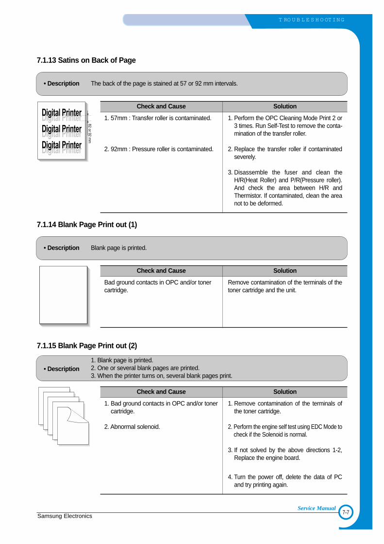
7-7Samsung Electronics
T RO U B L E S H O OTING
Service Manual
7.1.13 Satins on Back of Page
• Description The back of the page is stained at 57 or 92 mm intervals.
Digital Printer
Digital Printer
Digital Printer
Digital Printer
Digital Printer
Digital Printer
82 or 92 mm
Check and Cause Solution
1. 57mm : Transfer roller is contaminated.
2. 92mm : Pressure roller is contaminated.
1. Perform the OPC Cleaning Mode Print 2 or3 times. Run Self-Test to remove the conta-mination of the transfer roller.
2. Replace the transfer roller if contaminatedseverely.
3. Disassemble the fuser and clean theH/R(Heat Roller) and P/R(Pressure roller).And check the area between H/R andThermistor. If contaminated, clean the areanot to be deformed.
7.1.14 Blank Page Print out (1)
• Description Blank page is printed.
Digital PrinterDigital PrinterDigital PrinterDigital PrinterDigital Printer
Check and Cause Solution
Bad ground contacts in OPC and/or tonercartridge.
Remove contamination of the terminals of thetoner cartridge and the unit.
7.1.15 Blank Page Print out (2)
• Description1. Blank page is printed.2. One or several blank pages are printed.3. When the printer turns on, several blank pages print.
Check and Cause Solution
1. Bad ground contacts in OPC and/or tonercartridge.
2. Abnormal solenoid.
1. Remove contamination of the terminals ofthe toner cartridge.
2. Perform the engine self test using EDC Mode tocheck if the Solenoid is normal.
3. If not solved by the above directions 1-2,Replace the engine board.
4. Turn the power off, delete the data of PCand try printing again.

7-8
T RO U B L E S H O OTING
Samsung ElectronicsService Manual
7.2 The cause and solution of the bad discharge
7.2.1 Wrong Print Position
• Description Printing begins at wrong position on the paper.
Check and Cause Solution
Wrong sense time caused by defective feed sensoractuator.
Replace the defective actuator
7.2.2 JAM 0
• Description1. Paper is not exited from the cassette.2. Jam-0 occurs if the paper feeds into the printer.
Check and Cause Solution
1. Check the Solenoid by using EDCMode.
2. Check if the pad is loose due to badsealing of the side-pad.
3. Check the surface of the roller-pick-up for foreign matter.
4. If continuous clusters occur, checkwhether the assembly slot betweenshaft-pickup and housing-pickupopens or is broken away.
5. If the paper feeds into the printer andJam 0 occurs, perform EDC Mode tocheck feed-sensor of the engineboard.
1. Replace the solenoid.
2. Replace the side-pad Assembly L orR, if necessary.
3. Clean with soft cloth dampened withIPA(Isopropyl Alcohol) or water.
4. Replace the Main PBA and/or Sensor.

7-9Samsung Electronics
T RO U B L E S H O OTING
Service Manual
7.2.4 JAM 2
• Description1. Recording paper is jammed in front of or inside the fuser.2. Recording paper is stuck in the discharge roller and in the fuser just after passing through the
Actuator-Feed.
Check and Cause Solution
1. If the paper is completely fed out ofthe printer, but Jam 2 occurs : Exitsensor is defective.• After the paper is completely dis-
charged, actuator Exit should returnto the original position to shut thephoto-sensor. Sometimes it takeslonger hour than it should and doesnot return.
2. If the paper is rolled in the Fuser Roller:• This occurs when a Guide claw is
broken away or transformed.• It occurs when the Spring of a Guide
claw is broken away or transformed.• It occurs when the Heat-Roller or
Pressure-Roller is seriously contami-nated with the toner.
3. Paper is accordion in the fuser.
1. Check if the exit sensor actuator isdefective.• Check if the actuator exit is deformed
(Check if the lever part is deformedin shape).
• Check whether burrs occur in theassembly part of the actuator exit ornot and if the actuator is smoothlyoperated.
• Check if foreign matter and wire getcaught in the actuator exit's operation.
2. If the paper is stuck in the fuser : dis-assemble the fuser and remove thejammed paper, and clean the surfaceof the pressure roller with dry gauze.
3. Remove the jammed paper after disas-sembling the fuser : Clean the surfaceof the pressure roller with dry gauze.• Remove the toner particles stained
on the rib.• Check the assemblage and perfor-
mance of the exit.
7.2.3 JAM 1
• Description1. Recording paper is jammed in front of or inside the fuser.2. Recording paper is stuck in the discharge roller and in the fuser just after passing through the
Actuator-Feed.
Check and Cause Solution
1. If the recording paper is jammed infront of or inside the fuser.
2. If the recording paper is stuck in thedischarge roller and the fuser justafter passing through the Actuator-Feed, Feed Actuator may be defec-tive.
1. Replace the SMPS or Exit-Sensor.
2. Replace the Main PBA.
3. Reassemble the Actuator-Feed andSpring-Actuator if the movement isbad.
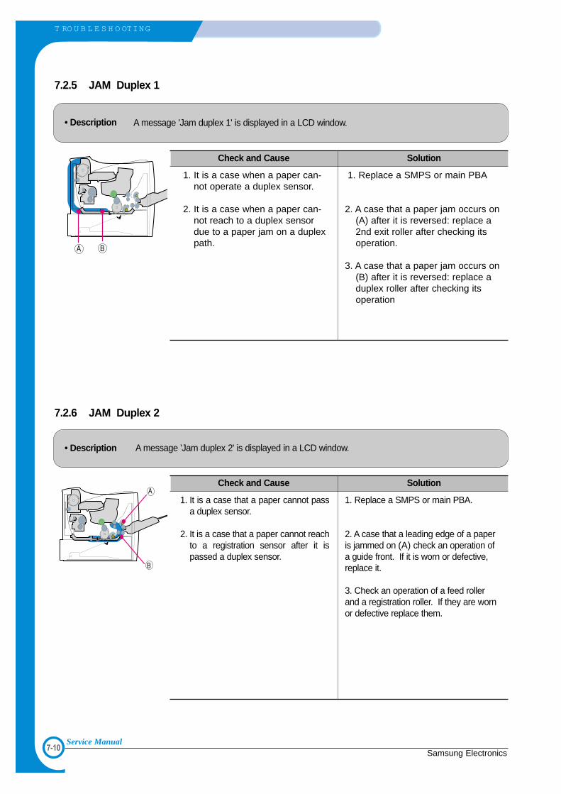
7-10
T RO U B L E S H O OTING
Samsung ElectronicsService Manual
7.2.6 JAM Duplex 2
• Description A message 'Jam duplex 2' is displayed in a LCD window.
Check and Cause Solution
1. It is a case that a paper cannot passa duplex sensor.
2. It is a case that a paper cannot reachto a registration sensor after it ispassed a duplex sensor.
1. Replace a SMPS or main PBA.
2. A case that a leading edge of a paperis jammed on (A) check an operation ofa guide front. If it is worn or defective,replace it.
3. Check an operation of a feed rollerand a registration roller. If they are wornor defective replace them.
7.2.5 JAM Duplex 1
• Description A message 'Jam duplex 1' is displayed in a LCD window.
Check and Cause Solution
1. It is a case when a paper can-not operate a duplex sensor.
2. It is a case when a paper can-not reach to a duplex sensordue to a paper jam on a duplexpath.
1. Replace a SMPS or main PBA
2. A case that a paper jam occurs on(A) after it is reversed: replace a2nd exit roller after checking itsoperation.
3. A case that a paper jam occurs on(B) after it is reversed: replace aduplex roller after checking itsoperation

7-11Samsung Electronics
T RO U B L E S H O OTING
Service Manual
7.2.7 Multi-Feeding
• Description Multiple sheets of paper are fed at once.
Check and Cause Solution
1. Solenoid malfunction(the solenoid does not workproperly): Perform EDC Mode.
2. Pad-Friction is contaminated with foreign matter.(oil...)
3. The face of paper is blended.
1. Replace the solenoid if necessary.
2. Replace the Main PBA.
3. Clean the pad friction with soft cloth dampened withIPA(Isopropyl Alcohol).
4. Use the smooth paper.
7.2.8 Paper rolled in the fuser
• Description If contaminated at intervals of 57mm on the back of a paper.
Check and Cause Solution
1. Contamination of the pressure roller or heatroller (Background, Hot off set).
2. Check the claw of the fuser whether it isdeformed.
1. After disassembling the fuser, clean contami-nation between the heat roller and the ther-mostor and remove the contamination of thepressure roller.
2. If there is heavy background, repair it by thebackground troubleshooting method.
3. Clean the surface of the heat roller with IPA orwater
4. Check the warp or separation of the print clawand the holder plate claw, and then manage it.

7-12
T RO U B L E S H O OTING
Samsung ElectronicsService Manual
7.2.9 Paper rolled on the OPC Drum
• Description Paper is rolled up in the OPC.
Check and Cause Solution
1. Paper is too much thin.
2. The face of paper is curled.
1. Recommend to use normal paper.
2. How to remove the rolled paper in the OPC.• Remove the paper while turning the OPC against
the ongoing direction. • Clean fingerprints on the OPC softly with soft
cloth dampened with tissue.

7-13Samsung Electronics
T RO U B L E S H O OTING
Service Manual
7.3 The cause and solution of the malfunction
7.3.1 Fuser Error
• Description A message "Open fuser/Over heat/Low heat' is displayed in a LCD panel.
Check and Cause Solution
1. Check whether a thermostat, AC wire, and heatlamp are open or not.
2. Check whether a thermistor is open or not.
3. Heat lamp ON/OFF test
4. It could not operate due to a gear of a fuser ismelted.
1. Replace the fuser if a thermostat is open.
2. Replace the fuser if a thermistor sensor islocated deep inside of a sponge.
3. Check whether the overheat mode circuitoperates normally or not.
4. Replace the fuser.
7.3.2 LSU Error
• Description A message "PMOTOR ERROR/HSYNC ERROR' is displayed in a LCD panel.
Check and Cause Solution
1. Check whether the LSU connector is disconnected ornot.
2. Check whether the LSU motor is rotating or not.
3. Check the HSYNC signal.
- Replace a LSU
- Replace a main board if the same error occurs againafter replacing a LSU.

7-14
T RO U B L E S H O OTING
Samsung ElectronicsService Manual
7.3.3 Not function of the gear of the fuser due to melting away
• Description The motor breaks away from its place due to gear melting away.
Check and Cause Solution
1. Check the Heat Lamp. 1. Replace the Fuser.
2. Replace the Main PBA.
2. Replace the SMPS.
7.3.4 Paper Empty
• Description The paper lamp on the operator panel is on even when paper is loaded in the cassette.
Check and Cause Solution
1. Bending or deformation of the actuator of the paper sen-sor.
2. The function of the engine board is defective
3. Check the Connector.
1. Replace the defective actuator.
2. Replace the Sensor PBA.

7-15Samsung Electronics
T RO U B L E S H O OTING
Service Manual
7.3.5 Paper Empty without indication
• Description The paper lamp on the operator panel does not come on when the paper cassette is empty.
Check and Cause Solution
1. Bending or deformation of the actuator of the paper sen-sor.
2. The function of the engine board is defective
1. Replace the defective actuator.
2. Replace the engine board.
7.3.6 Cover Open
• Description The ERROR lamp is on even when the print cover is closed.
Check and Cause Solution
1. The hook lever in the top cover may be defective.
2. Check the connector and circuit of the cover switchdepartment in the Main Control board.
1. Replace the hook lever, if defective.
2. Check the insertion of the Cover Open S/WConnect.
3. Replace the Main Control board or Cover OpenS/W.

7-16
T RO U B L E S H O OTING
Samsung ElectronicsService Manual
7.3.7 No error message when the cover is open
• Description The ERROR message does not come on even when the printer cover is open
Check and Cause Solution
1. Check the connector and circuit of the cover switchdepartment in the Main Control board. Perform EDCmode
1. Check the insertion of the Cover Open S/WConnect.
2. Replace the Main Control board or Cover OpenS/W.

7-17Samsung Electronics
T RO U B L E S H O OTING
Service Manual
7.3.8 Defective motor operation
• Description Main motor is not driving when printing, and paper does not feed into the printer, resulting 'Jam 0'.
Check and Cause Solution
1. The Motor harness or Motor PCB may be defective.
2. Check the motor operation in the EDC Mode.
1. Check the motor harness, replace it, if defective.
2. Replace the Main PBA.
7.3.9 No Power
• Description When system power is turned on, all lamps on the operator panel do not come on.
Check and Cause Solution
1. Check if the power input and SMPS output are normal.
2. Check the inferiority of LED-Panel or LDC window on thefront-cover if the OP panel does not appear after normalwarming-up.
1. Replace the power supply cord or SMPS.
2. Replace the control board.
3. Replace the OP panel.

7-18
T RO U B L E S H O OTING
Samsung ElectronicsService Manual
7.3.10 Vertical Line Getting Curved
• Description When printing, vertical line gets curved.
Check and Cause Solution
1. If the supply of +24v is unstable in the Main Control boardlinking with LSU, check drive by EDC Mode: LSU Check.
2. Chect the Deve PBA in the Toner Cartridge.
1. Replace LSU.
2. Replace theToner Joint PBA.
2. Replace the MainPBA.

7-19Samsung Electronics
T RO U B L E S H O OTING
Service Manual
7.4 Toner Cartridge Service
It is not guaranteed for the default caused by using other toner cartridge other than the cartridge supplied by the
Samsung Electronic or caused by non-licensed refill production.
7.4.1 Precautions on Safe-keeping of Toner CartridgeExcessive exposure to direct light more than a few minutes may cause damage to the cartridge.
7.4.2 Service for the Life of Toner CartridgeIf the printed image is light due to the life of the toner, you can temporarily improve the print quality by redistributing the
toner(Shake the toner cartridge), however, you should replace the toner cartridge to solve the problem thoroughly.
7.4.3 Distinguish function for choice cartridge
• Distinguish function for choice cartridgeAn EEP ROM is mounted to a cartridge for distinguishing a choice developer. Items written in below are
detected by checking up memory information.
If the data of the EEP ROM is broken, it cannot be detected.
1) Detecting existence of a toner cartridge: It detects whether a toner cartridge is mounted or not.
2) Detecting a serial no of a developer: If a serial no code is different with a supplying company°Øs
serial no., it is not operated.
3) Detecting a developer supplying company: If it is not Samsung’s, it is not operated.
4) Detecting page counter: It detects the life span of a developer.
5) Detecting an OPC rotating counter: It detects the life span of an OPC drum.
• Distinguish a refilled cartridge. (with eyes)1) Check whether One-way screw is damaged or not
2) Check the page counter (Print out the self-test configuration)
: Even though a toner has left a lot, a page counter is over 8K (7~8K). It is suspected as a
refilled cartridge.

7-20
T RO U B L E S H O OTING
Samsung ElectronicsService Manual
7.4.4 Error message (LCD window) related in a toner sensorIt explains a message related in toner sensor in a LCD.
7.4.4.1 Invalid Toner- Contents: It is displayed when a supplier is different between a developer and a set. If this message is shown up, a
printing process cannot operate.
- Solution: Attach a suitable developer (the same supplier's) to a set. (A unique key has been applied.)
7.4.4.2 Low Toner- Contents: This message shows up when a message "remaining toner: 10%" is displayed in a cartridge count informa-
tion. And the same message shows up when an OPC count becomes 18,000 (page).
- Solution: It means that a toner in the developer has been almost ended. Replace the developer.
7.4.4.3 Replace Cartridge- Contents: This message shows up when an OPC count becomes 20,000 (pages). It means the life span of a toner
cartridge (except a toner part) has been ended. Even though a case that a toner is refilled, the rest of major
parts have been ended, so entire toner cartridge might be replaced.
- Solution: If an OPC rotates about 20,000 (page), in a worst case, a toner overflows and it may cause a system fail.
Therefore, recommend a user to replace a developer. When continuously using, even though a count reach-
es to 20,000 pages, a printed image becomes misty, and an on-line key that is flashing on a set must be
pressed for a single print.

7-21Samsung Electronics
T RO U B L E S H O OTING
Service Manual
7.4.5 Signs and Measures at Poor toner cartridge
Fault Signs Cause & Check Solution
Light image andpartially blankimage(The life is ended.)
TonerContamination
• The printed imageis light or uncleanand untidy.
• Some part of theimage is not print-ed.
• Periodically a noiseas "tick tick" occurs.
• Toner is fallen onthe papers periodi-cally.
• Contaminated withtoner on prints part-ly or over the wholesurface.
1. If the image is light or uncleanand untidy printed image -Shake the toner cartridge andthen recheck.
(1)NG: Check the weight of thetoner cartridge
(2)OK: Lack of toner, so the lifeis nearly closed.
2. Some part of image is notprinted - Shake the tonercartridge and then recheck.
(1)NG: Check the weight of thetoner cartridge andclean the LSU windowwith a cotton swab,then recheck.
(2)OK: Lack of toner, so the lifeis nearly closed.
3. Periodically a noise as "ticktick" occurs - Measure thecycle and the weight of thetoner cartridge.
4. White vertical stripes on thewhole screen or partly : Check the weight of the tonercartridge.
1. Toner is fallen on the paperperiodically.
(1)Check the cycle of thefalling of the toner.
(2)Check the appearance ofboth ends of the toner car-tridge OPC drum.
2.The center of the printed mat-ter is contaminated with toner.(1)Check whether foreign sub-
stances or toner are stuckto the terminal (contactpoint) of the toner cartridge.
(2)Check whether the state ofthe terminal assembly isnormal.
1. All of 1, 2, 3 above-If it become better by shaking,replace with a new toner car-tridge after 50-100 sheets in theclosing state of the life span.
2. In case of 2-If it becomes better after clean-ing the LSU window, then thetoner cartridge is normal.(Because of foreign substanceon the LSU window, the imagehas not been printed partly.)
3. In case of 3-If the cycle of noise is about 2seconds, the toner inside thetoner cartridge has been nearlyexhausted.( Purchase andreplace with a new toner car-tridge after using about 200sheets at the point of occur-rence)
4. In case of 3-This is a phenomenon causedby lack of toner, so replace witha new toner cartridge.
1. If both ends of the OPC drumare contaminated with toner:Check the life of the toner car-tridge.
2. Check whether it could be recy-cled.
3. If it cannot be recycled:Replace the toner cartridge.
Digital PrinterDigital PrinterDigital PrinterDigital PrinterDigital Printer
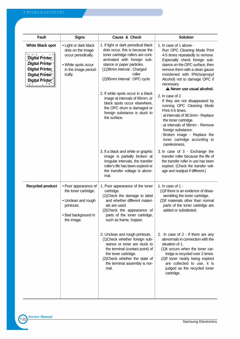
7-22
T RO U B L E S H O OTING
Samsung ElectronicsService Manual
Fault Signs Cause & Check Solution
White Black spot
Recycled product
• Light or dark blackdots on the imageoccur periodically.
• White spots occurin the image period-ically.
• Poor appearance ofthe toner cartridge.
• Unclean and roughprintouts.
• Bad background inthe image.
1. If light or dark periodical blackdots occur, this is because thetoner cartridge rollers are cont-aminated with foreign sub-stance or paper particles.(1)38mm interval : Charged
roller(2)95mm interval : OPC cycle
2. If white spots occur in a blackimage at intervals of 95mm, orblack spots occur elsewhere,the OPC drum is damaged orforeign substance is stuck tothe surface.
3. If a black and white or graphicimage is partially broken atirregular intervals, the transferroller's life has been expired orthe transfer voltage is abnor-mal.
1. Poor appearance of the tonercartridge.
(1)Check the damage to labeland whether different materi-als are used.
(2)Check the appearance ofparts of the toner cartridge,such as frame, hopper.
2. Unclean and rough printouts.(1)Check whether foreign sub-
stance or toner are stuck tothe terminal (contact point) ofthe toner cartridge.
(2)Check whether the state ofthe terminal assembly is nor-mal.
1. In case of 1 above -Run OPC Cleaning Mode Print4-5 times repeatedly to remove.Especially check foreign sub-stance on the OPC surface, thenremove them with a clean gauzemoistened with IPA(IsopropylAlcohol) not to damage OPC ifnecessary.
Never use usual alcohol.
2. In case of 2If they are not disappeared byrunning OPC Cleaning ModePrint 4-5 times. : at intervals of 38.5mm - Replacethe toner cartridge.
: at intervals of 96mm - Removeforeign substance.
: Broken image - Replace thetoner cartridge according tocarelessness.
3. In case of 3 - Exchange thetransfer roller because the life ofthe transfer roller in use has beenexpired. (Check the transfer volt-age and readjust if different.)
1. In case of 1 -(1)If there is an evidence of disas-
sembling the toner cartridge.(2)If materials other than normal
parts of the toner cartridge areadded or substituted.
2. In case of 2 - If there are anyabnormals in connection with thesituation of 1.(1)It occurs when the toner car-
tridge is recycled over 2 times.(2)If toner nearly being expired
are collected to use, it isjudged as the recycled tonercartridge.
Digital PrinterDigital PrinterDigital PrinterDigital PrinterDigital Printer

7-23Samsung Electronics
T RO U B L E S H O OTING
Service Manual
Fault Signs Cause & Check Solution
Ghost & ImageContamination
• The printed imageis too light or dark,or partially contami-nated black.
• Totally contaminat-edblack.(Black image print-ed out)
• The density of print-outs is too dark andghost occurs.
1. The printed image is too lightor dark, or partially contami-nated black.
(1)Check whether foreign sub-stance or toner are stuck tothe terminal(point of contact)of the toner cartridge.
(2)Check whether the terminalassembly is normal.
2. Totally contaminated black.(Black image printed out)
(1)Check whether foreign sub-stances are stuck to the ter-minal(point of contact) of thetoner cartridge and the stateof assembly. (Especially check thecharged roller terminal.)
3. The printed image is dark andghost occurs.
(1)Check foreign substanceattached to the terminal(point of contact) of thetoner cartridge and the stateof assembly. (Especially check the devel-oping roller terminal.)
1. All of 1, 2, 3 above(1)Remove toner and foreign sub-
stances adhered to the contactpoint of the toner cartridge.
(2)The contact point of the unitfacing that of the toner car-tridge also must be cleaned.
(3)If the terminal assembly isunsafe:
• Fully stick the terminal to orreassemble it after disassem-bling.
• Disassemble the side plate andpush the terminal to be stuck,then reassemble it.
2. In case of 2It is a phenomenon when theOPC drum of the toner cartridgeis not electrically charged. Cleanthe terminals of the chargedroller, then recheck it.
3. In case of 3It is a phenomenon as the devel-oping bias voltage of the tonercartridge. Clean the terminals ofthe developing roller, thenrecheck it.

7-24
T RO U B L E S H O OTING
Samsung ElectronicsService Manual
7.5 The cause and solutions of bad environment of the software
7.5.1 The printer is not working (1)
• Description While Power turned on, the printer is not working in the printing mode.
Check and Cause Solution
1. Run Self-Test Mode: Turn the power on while pressingthe test printing button for 2 or 3 seconds before printingworks.
2. Check if the PC and the printer is properly connectedand the toner cartridge installed.
3. Printing is nor working in the Windows.
4. Check if the printer cable is directly connected to periph-eral devices
1.Check the power of the printer and perform the Self-Test. If the test printing works, that means no prob-lems in the printer itself. If the test printing does notwork, that means bad functioning of the printer(notbecause of software).
2. Replace the printer cable. If the problems not solvedeven after the cable replaced, check the amount ofthe remaining tone.(refer to Toner Cartridge Service 4-5)
3. Check if the connection between PC and printer portis proper. If you use windows, check if the printer dri-ver in the controller is set up. If the printer driver isproperly set up, check in which program the printingis not working. The best way to find out is to open thememo pad to check the function of printing. If it is notworking in a certain program, adjust the setup theprogram requires. Sometimes, the printout is normalwithin the Windows basic programs, but it's not work-ing in a particular program. In such case, install thenew driver again. If not working in the Windows basicprogram, Check the setup of the port of CMOS is onECP. And check the address of IRQ 7 and 378
4. If the scanner needs to be connected to the printer,first the remove the scanner from the PC to see if theprinter is properly working alone.

7-25Samsung Electronics
T RO U B L E S H O OTING
Service Manual
7.5.2 The printer is not working (2)
• Description After receiving the printing order, no response at all or the low speed of printing occurs due to wrong setup of the environment rather than malfunction of the printer itself.
Check and Cause Solution
1. Secure more space of the hard disk.
2. Printing error occurs even if there is enough space inthe hard disk.
3. Check the parallel-port-related items in the CMOSSetup.
4. Reboot the system to print.
1. Not working with the message 'insufficient printermemory' means hard disk space problem rather thanthe RAM problem. In this case, provide more spacefor the hard disk. Secure more space using the diskutilities program.
2. The connection of the cable and printer port is notproper. Check if the connection is properly done andif the parallel port in CMOS is rightly set up.
3. As a printer port, Select ECP or SPP amongSPP(Normal), ECP, and EPP modes(increase print-ing speed) SPP normal mode support 8-bit datatransfer, while ECP Mode transfer the 12-bit data.
4. If the regular font is not printing, the cable or theprinter driver may be defective.Turn the PC and printer off, and reboot the systemto print again. If not solved, double-click the printer inmy computer If the regular fonts are not printed thistime again. the cable must be defective so replacethe cable with new one.
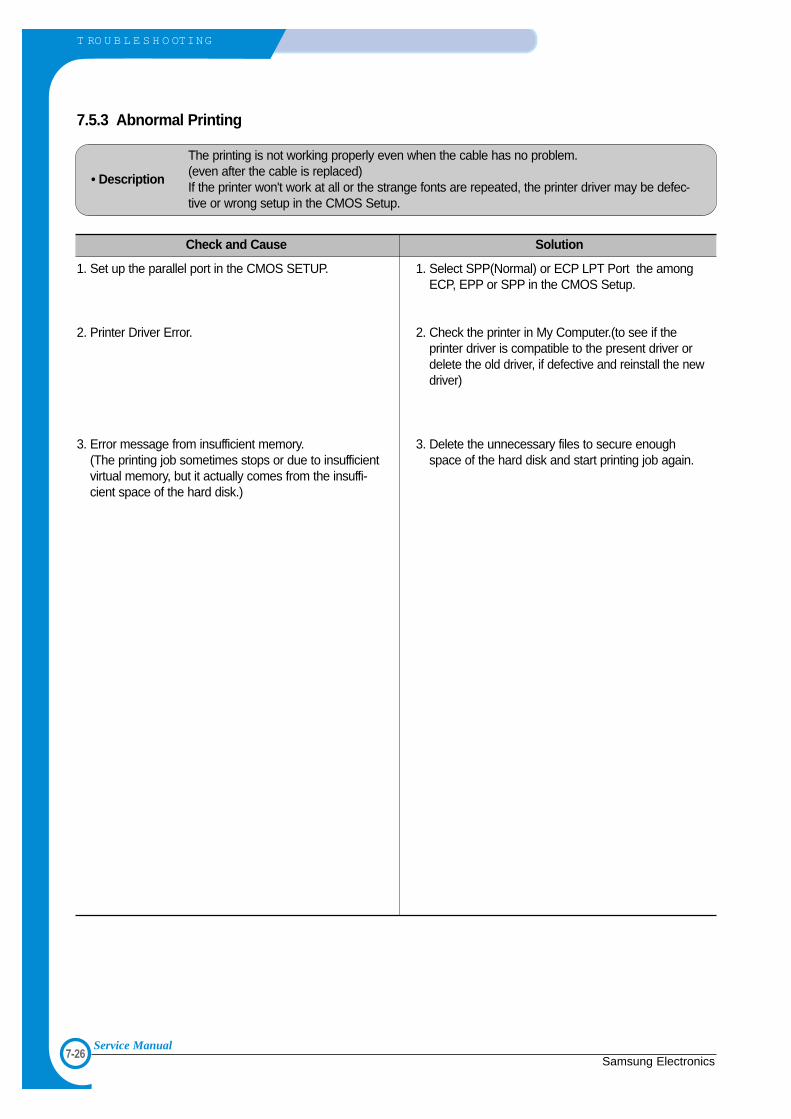
7-26
T RO U B L E S H O OTING
Samsung ElectronicsService Manual
7.5.3 Abnormal Printing
• Description
The printing is not working properly even when the cable has no problem.(even after the cable is replaced) If the printer won't work at all or the strange fonts are repeated, the printer driver may be defec-tive or wrong setup in the CMOS Setup.
Check and Cause Solution
1. Set up the parallel port in the CMOS SETUP.
2. Printer Driver Error.
3. Error message from insufficient memory. (The printing job sometimes stops or due to insufficientvirtual memory, but it actually comes from the insuffi-cient space of the hard disk.)
1. Select SPP(Normal) or ECP LPT Port the amongECP, EPP or SPP in the CMOS Setup.
2. Check the printer in My Computer.(to see if theprinter driver is compatible to the present driver ordelete the old driver, if defective and reinstall the newdriver)
3. Delete the unnecessary files to secure enoughspace of the hard disk and start printing job again.

7-27Samsung Electronics
T RO U B L E S H O OTING
Service Manual
7.5.4 SPOOL Error
• Description
To spool which stands for "simultaneous peripheral operations online" a computer document ortask list (or "job") is to read it in and store it, usually on a hard disk or larger storage medium sothat it can be printed or otherwise processed at a more convenient time (for example, when aprinter is finished printing its current document).
Check and Cause Solution
1. Insufficient space of the hard disk in the directoryassigned for the basic spool.
2. If the previous printing error not solved.
3. When expected to collide with other program.
4. When an application program or the printer driver isdamaged.
5. When some files related to OS are damaged or virusinfected.
6. Memory is less than suggested one.
1. Delete the unnecessary files to provide more spaceto start printing job.
2. If there are some files with the extension name of****.jnl, Delete them and Reboot the Windows torestart printing job.
3. Shut down all other programs except the currentone, if possible.
4. Delete the printer driver completely and reinstall it.
5 After rebooting the computer, check for viruses,restore the damaged files and reinstall the programto do the printing job.
6. Add up enough memory to the PC.
How to delete the data in the spool manager.
In the spool manager, the installed drivers and the list of the documents waiting to be printed are shown. Select the document to be deleted and check the delete menu.
If you intend to delete the current document being printed, the data being transferred to the printer will be putout and then the document is removed. Before choosing the document, the menu is still inactive.
Or put the document out of the list and repeat the routine as in the above or finish the spool manager.

7-28
T RO U B L E S H O OTING
Samsung ElectronicsService Manual

Exploded Views & Parts List
Samsung ElectronicsService Manual 8-1
888.1 Main Assembly p.8-2
8.2 Base-Houshing Assembly p.8-6
8.3 Frame Assembly (1) p.8-7
Frame Assembly (2) p.8-8
8.4 Fuser Assembly p.8-13
8.5 Main Driver Assembly p.8-16
8.6 Exit Driver Assembly p.8-17
8.7 Regi Assembly p.8-18
8.8 SMPS Assembly p.8-19
8.9 Cassette Assembly p.8-21
8.10 SCF Assembly p.8-23
8. Exploded Views and Parts List
Contents
Part Number & Description format.
There are two types of Part number format.
Part numbers and descriptions are defined according to a company standard. The information below will help you to understand the part number format and assist when ordering spare parts.
This format is used throughout Samsung on all product ranges. Typically it is used for small components and electronic parts.
This format is controlled by individual Samsung Divisions and is used on specific products, typically for mechanical parts. Type 2 format part numbers fall into 2 categories:
Assemblies consisting of 2 or more parts. Also used for Service manuals, user guides and diagrams.
Ass’y parts and A/S privately used Parts can be distinguished by the part Code and Description. They are always Type 2 format. The 2 leading characters indicate private or assembly parts.
number letter

Samsung ElectronicsService Manual
Exploded Views & Parts List
8-2
8.1 Main Assembly
0
3
2-1
2-2
2
4
5
3-1
3-2
3-33-4
3-4
3-5
3-6
1
7
16
11
3238
30
13
18
8
6
14
14-2
14-114-3
17
33
9 22
34
22
29 28
44
19
20
45
31
20
20
2736
35
27-1
27-227-3
42
24 24-1
24-2
24-4
24-3
25
25-125-225-3
43
23
21
26
3710
41(ML-2551N only)
41-1
41-2
39
40
15

Exploded Views & Parts List
Samsung ElectronicsService Manual 8-3
Main Assembly Parts List(1/2)
No. Location Description SEC.Code Q’ty SA Remark
1 H6001 ELA HOU BASE-HOUSING ; SEC JC96-02695T 1 X ML-2550
ELA HOU BASE-HOUSING ; SEC JC96-02695W 1 X ML-2551N
2 Z2293 ELA UNIT-COVER MP ; ML-2060A,SEC,220V JC96-02679A 1 O
2-1 Z2204 COVER-M-MP ; ML-2060,ABS,V0,SEC JC63-00127A 1 O
2-2 T4136 TRAY-M-EXTEND MP ; ML-2060,ABS JC63-00128A 1 O
3 K3145 ELA UNIT-KNOCKUP MP ; ML-2060A,SEC,220V JC96-02680A 1 O
3-1 P5146 PLATE-M-KNOCK UP MP ; ML-2060,ABS JC61-00686A 1 O
3-2 G2299 PMO-SIDE GUIDE MP(L) ; ML-2060,PC+ABS JC72-01005A 1 O
3-3 G2301 PMO-SIDE GUIDE MP(R) ; ML-2060,PC+ABS JC72-01006A 1 O
3-4 K5006 PMO-IDLE KNOCK UP MP ; ML-2060,POM,WHITE JC72-01004A 2 O
3-5 P0019 MPR-PAD KNOCK UP MP ; ML-6060A,CR+CORK JC74-00011A 1 X
3-6 G0369 GEAR-PINION ; SF4000,POM,WHT,M1,Z16 JG66-40003A 1 O
4 T4137 TRAY-M-LINK MP(L) ; ML-2060,HIPS JC63-00129A 1 O
5 T4138 TRAY-M-LINK MP(R) ; ML-2060,HIPS JC63-00130A 1 O
6 K3096 ELA UNIT-CASSETTE(550) ; ML-2150,SEC JC96-02845A 1 O
7 B0075 ELA UNIT-FRAME BASE ; ML-2550,SEC,110V JC96-02627F 1 O 110V
ELA UNIT-FRAME BASE ; ML-2550,SEC,220V JC96-02627G 1 O 220V
8 T2060 ELA UNIT-DEVE KIT ; ML-2550,SAMSUNG JC96-02640G 1 O 110V
ELA UNIT-DEVE KIT ; ML-2550,SAMSUNG JC96-02640J 1 O 220V
9 K3171 ELA UNIT-REGI ; ML-2060A,SEC,220V JC96-02626A 1 O
10 Z1024 PBA MAIN-CONTROLLER JC92-01487B 1 O
11 M2098 ELA UNIT-MOTOR MAIN CAR 25 ; ML-2550,XEROX JC96-02725B 1 O
12 M2097 ELA UNIT-MOTOR EXIT CARDINAL2 ; ML-2550,XE JC96-02857A 1 O
13 S7016 ELA HOU-SMPS_HVPS_V1(110V) ; ML-2550,SEC JC96-02779B 1 X 110V
ELA HOU-SMPS_HVPS_V2(220V) ; ML-2550,SEC JC96-02777B 1 X 220V
14 K3567 MEA UNIT-GUIDE FRONT, DUP ; ML-2150,SEC JC97-01715A 1 O
14-1 G2085 GUIDE-P-FRONT, DUP ; ML-2060,SECC,0.8,76 JC61-00660A 1 O
14-2 L4035 LEVER-M-OPEN, DUP ; ML-2060,PC,2.5,12,40 JC66-00443A 1 O
14-3 H1067 CBF HARNESS-EARTH (TX MOTOR) ; SF-3100,CBF JC39-00017A 1 O None N/W Card
15 D2001 BRACKET-P-BLADE ; ML-2060,SECC,1.2,20,230 JC61-00634A 1 X ML-2550 Only
16 L7044 UNIT-LSU_CARDINAL_25 ; ML-2550,600DPI JC59-00019B 1 O
17 K2861 BAR-P_CROSS BOTTOM ; ML-2060,SECC T1 JC71-00042A 2 O
18 K3816 PMO-ACTUATOR EMPTY ; ML-2060,PC,BLK JC72-00991A 1 O
19 F5016 FAN-DC CARDINAL ; AD0424LS-C50 JC31-00029A 1 O
20 F5029 STOPPER-M-FAN80 ; ML-2060,ABS,BLK JC61-00667A 3 O
21 G0439 GEAR-TR29 ; ML-6060A,POM,BLK,0.6,29 JC66-00039A 1 O
22 G0415 GEAR-REGI Z25 ; ML-2060,M90-44,0.8,25,5.6 JC66-00420A 2 O
23 Z3014 ROLLER-TRANSFER ; ML-2060,NBR SPONGE+SUM/N JC66-00540A 1 O
24 K3139 ELA UNIT-HOLDER TR R ; ML-6060A,SAMSUNG JC96-01729A 1 O
24-1 K3741 PMO-TRANSFER HOLDER R ; ML-6060A,ABS,PANTO JC72-41145C 1 X
24-2 K3852 PMO-BUSHING TR ; ML-5000A,POM,BLK JC72-41142A 1 X
24-3 Z4278 SPRING-TR R HAWK ; ML-6060A,SUS 304 WPB JC61-00046A 1 X
24-4 K3379 IPR-PLATE TR ; ML-5000A,BSBM1/2H,T0.2 JC70-11053A 1 X
SA : Service AvailableO : Service available X : Service not available
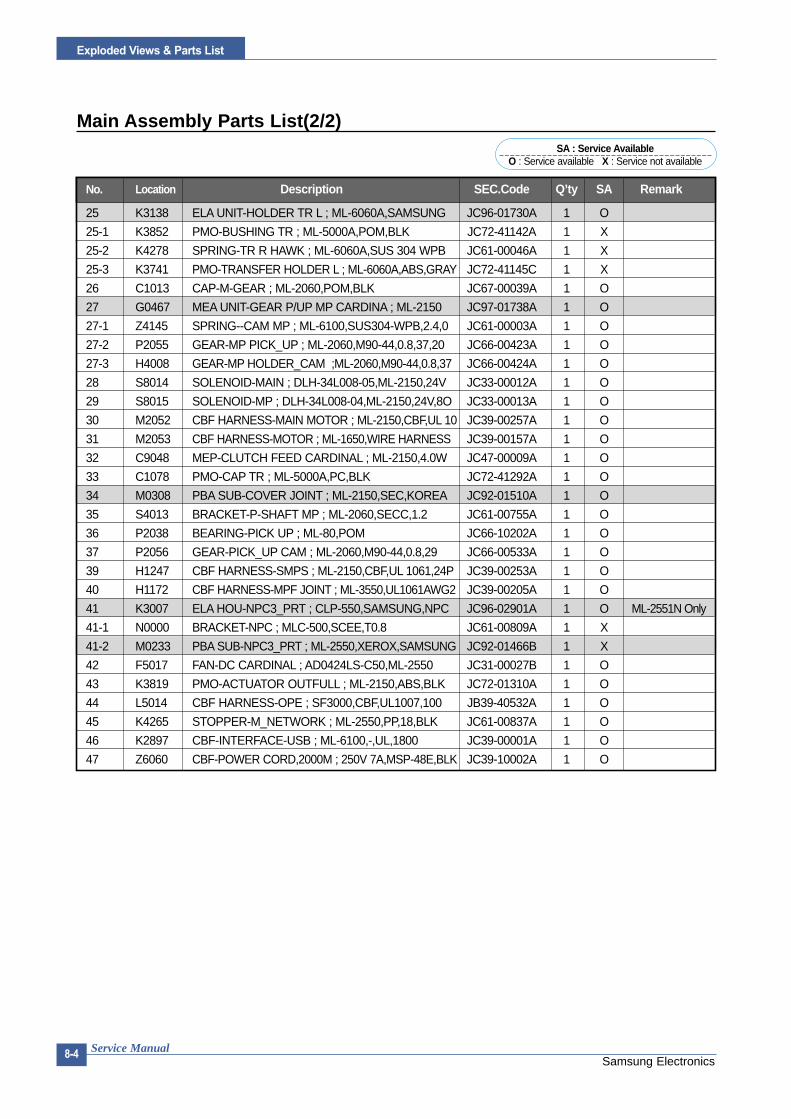
Samsung ElectronicsService Manual
Exploded Views & Parts List
8-4
Main Assembly Parts List(2/2)
No. Location Description SEC.Code Q’ty SA Remark
25 K3138 ELA UNIT-HOLDER TR L ; ML-6060A,SAMSUNG JC96-01730A 1 O
25-1 K3852 PMO-BUSHING TR ; ML-5000A,POM,BLK JC72-41142A 1 X
25-2 K4278 SPRING-TR R HAWK ; ML-6060A,SUS 304 WPB JC61-00046A 1 X
25-3 K3741 PMO-TRANSFER HOLDER L ; ML-6060A,ABS,GRAY JC72-41145C 1 X
26 C1013 CAP-M-GEAR ; ML-2060,POM,BLK JC67-00039A 1 O
27 G0467 MEA UNIT-GEAR P/UP MP CARDINA ; ML-2150 JC97-01738A 1 O
27-1 Z4145 SPRING--CAM MP ; ML-6100,SUS304-WPB,2.4,0 JC61-00003A 1 O
27-2 P2055 GEAR-MP PICK_UP ; ML-2060,M90-44,0.8,37,20 JC66-00423A 1 O
27-3 H4008 GEAR-MP HOLDER_CAM ;ML-2060,M90-44,0.8,37 JC66-00424A 1 O
28 S8014 SOLENOID-MAIN ; DLH-34L008-05,ML-2150,24V JC33-00012A 1 O
29 S8015 SOLENOID-MP ; DLH-34L008-04,ML-2150,24V,8O JC33-00013A 1 O
30 M2052 CBF HARNESS-MAIN MOTOR ; ML-2150,CBF,UL 10 JC39-00257A 1 O
31 M2053 CBF HARNESS-MOTOR ; ML-1650,WIRE HARNESS JC39-00157A 1 O
32 C9048 MEP-CLUTCH FEED CARDINAL ; ML-2150,4.0W JC47-00009A 1 O
33 C1078 PMO-CAP TR ; ML-5000A,PC,BLK JC72-41292A 1 O
34 M0308 PBA SUB-COVER JOINT ; ML-2150,SEC,KOREA JC92-01510A 1 O
35 S4013 BRACKET-P-SHAFT MP ; ML-2060,SECC,1.2 JC61-00755A 1 O
36 P2038 BEARING-PICK UP ; ML-80,POM JC66-10202A 1 O
37 P2056 GEAR-PICK_UP CAM ; ML-2060,M90-44,0.8,29 JC66-00533A 1 O
39 H1247 CBF HARNESS-SMPS ; ML-2150,CBF,UL 1061,24P JC39-00253A 1 O
40 H1172 CBF HARNESS-MPF JOINT ; ML-3550,UL1061AWG2 JC39-00205A 1 O
41 K3007 ELA HOU-NPC3_PRT ; CLP-550,SAMSUNG,NPC JC96-02901A 1 O ML-2551N Only
41-1 N0000 BRACKET-NPC ; MLC-500,SCEE,T0.8 JC61-00809A 1 X
41-2 M0233 PBA SUB-NPC3_PRT ; ML-2550,XEROX,SAMSUNG JC92-01466B 1 X
42 F5017 FAN-DC CARDINAL ; AD0424LS-C50,ML-2550 JC31-00027B 1 O
43 K3819 PMO-ACTUATOR OUTFULL ; ML-2150,ABS,BLK JC72-01310A 1 O
44 L5014 CBF HARNESS-OPE ; SF3000,CBF,UL1007,100 JB39-40532A 1 O
45 K4265 STOPPER-M_NETWORK ; ML-2550,PP,18,BLK JC61-00837A 1 O
46 K2897 CBF-INTERFACE-USB ; ML-6100,-,UL,1800 JC39-00001A 1 O
47 Z6060 CBF-POWER CORD,2000M ; 250V 7A,MSP-48E,BLK JC39-10002A 1 O
SA : Service AvailableO : Service available X : Service not available

Exploded Views & Parts List
Samsung ElectronicsService Manual 8-5
8.2 Base-Houshing Assembly
1
1-1
1-21-3
1-31-18
1-41-5
1-6
1-7
1-12
1-13
1-14
1-14
1-16
1-17
5
3
2
3-1
3-5
3-2
3-8
3-33-73-6
3-4
0
4
2-1
2-2
6
1-8
1-151-11
1-9
1-10
3-9

Samsung ElectronicsService Manual
Exploded Views & Parts List
8-6
Base-Houshing Assembly Parts List
No. Location Description SEC.Code Q’ty SA Remark
0 H6001 ELA HOU BASE-HOUSING ; SEC,USA,11 JC96-02695T 1 X ML-2550
ELA HOU BASE-HOUSING ; SEC,USA,11 JC96-02695W 1 X ML-2551N
1 Z2299 ELA UNIT-COVER TOP ; SEC,USA,11 JC96-02696T 1 O ML-2550
ELA UNIT-COVER TOP ; SEC,USA,11 JC96-02696W 1 O ML-2551N
1-1 Z2168 COVER-M_TOP ; ML-2551N,ABS ,2.5,V0 JC63-00119R 1 O ML-2550
COVER-M_TOP ; ML-2551N,ABS ,2.5,V0 JC63-00119V 1 O ML-2551N
1-2 B5010 MEC- BRUSH ANTISTATIC ; ML-6060A,SEC,NTR JC75-00095A 1 O
1-3 L4034 LEVER-M_STACKING 25 ; ML-2550,PCABS,0.2,24 JC66-00646B 2 O
1-4 K2882 BUSH-M-RETAINER ; ML-2060,POM JC61-00657A 1 O
1-5 Z4169 SPRING ETC-DUPLEX COVER ; ML-9400W,SUS304W JC61-00391A 1 O
1-6 L6053 PMO-STACKER LOCKER ; ML-2060,ABS,0810 JC72-00995A 1 O
1-7 K4284 WINDOW-M-LCD ; ML-2060,ACRYL,TRANS JC64-00048A 1 O
1-8 K0033 KEY-M-BUTTON ; ML-2060,ABS JC64-00045A 1 O
1-9 K2377 PBA MAIN-LCD PANEL ; ML-2150,SEC,KOREA,LCD JC92-01473A 1 X
1-10 K0037 KEY-M-DUPLEX ; ML-2060,ACRYL,NATURAL JC64-00044A 1 O
1-11 K0045 KEY-M-ON LINE ; ML-2060,ACRYL,NATURAL JC64-00046A 1 O
1-12 Z2213 COVER-M-OPEN ; ML-2060,ABS,V0 JC63-00116A 1 O
1-13 S5090 PMO-STACKER_RX ; ML-2150,ABS,LIGHT GRAY JC72-00973B 1 O
1-14 H3073 STOPPER-M-HINGE OPEN ; ML-2060,ABS JC61-00656A 2 O
1-15 K0049 KEY-M-SAVE MODE ; ML-2060,ACRYL,NATURA JC64-00047A 1 O
1-16 Z2496 PBA SUB-COVER OPEN ; ML-2150,SEC,KOREA JC92-01514A 1 O
1-17 S3037 CAP-M-SENSOR ; ML-2060,ABS,2.5 JC67-00034A 1 X
1-18 Z2247 COVER-WINDOW ; ML-2150,PVC FILM,T0.15,78MM JC63-00256A 1 X
2 Z2298 ELA UNIT-COVER RIGHT ; ML-2060,SEC,220V JC96-02697A 1 O
2-1 Z2224 COVER-M-RIGHT ; ML-2060,ABS JC63-00115A 1 O
2-2 B3006 BUTTON-M-POWER ; ML-2060,ABS,V0 JC64-00043A 1 O
3 Z2421 MEA UNIT-COVER REAR ; ML-2150,SEC,USA JC97-01743A 1 O
3-1 Z2220 COVER-M-REAR ; ML-2060,ABS,V0 JC63-00120A 1 O
3-2 Z5062 PMO-STACKER REAR ; ML-2060,ABS,0810P JC72-00996A 1 O
3-3 F6217 SPRING-TS ; SWRS 82A,-,PI0.8,D11.5,-,N11.5 6107-001157 2 O
3-4 G2059 GUIDE-M-DUPLEX ; ML-2060,PC,BLK JC61-00658A 2 O
3-5 K3247 ICT-BRKT REAR COVER ; ML-7000,SPCC,T1.2,ZN JC70-00007A 1 X
3-6 S4049 IEX-SHAFT IDLE,F/UP ; ML-5000A,SUS304 JC70-20901A 2 O
3-7 K3804 PEX-ROLLER F/UP(2) ; ML-5000A,TE JC72-20902A 2 O
3-8 D2086 PMO-DUMMY FRAME FUSER ; ML-2060,PET G/F20% JC72-00999A 1 O
3-9 E1008 IPR-TENSION PLATE ; ML-2150,SUS304,T0.25 JC70-00465A 1 X
4 Z2196 COVER-M-LEFT ; ML-2060,ABS,V0 JC63-00117A 1 O
5 Z2191 COVER-M-FRONT INNER ; ML-2060,ABS,VO JC63-00118A 1 O
6 Z2189 COVER-M-FRAME EXIT ; ML-2060,ABS,2.5 JC63-00122A 1 O
SA : Service AvailableO : Service available X : Service not available

Exploded Views & Parts List
Samsung ElectronicsService Manual 8-7
8.3 Frame Assembly (1)
1
2
6
6
2-1
7
2-22-2
2-3
2-4
2-4 -1
2-4-2
2-4-3
7-1
7-2
7-3
7-8
7-4
7-5
7-6
7-7
5
14
15
16
16
15
8
13
9
10
1919-1
19-2
19-3
19-4
19
20
34
37 21
22
23
20
73
24
7374
1112
28
4
3
26
2729
13
30
17
3132
66
3636-1
36-3
36-2
0
60
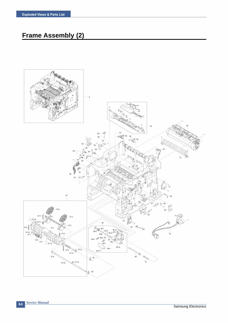
Samsung ElectronicsService Manual
Exploded Views & Parts List
8-8
Frame Assembly (2)
53
67
68
69
67-167-2
67-3
67-367-4
67-5
67-567-13
67-7
67-9
67-667-7
67-8
67-12
67-9
67-10 67-13
39
67-11
68-168-13
68-S68-5
70
39
42
65
45
46
47 48
49
50
72
51
57
56 58
5659
41
60
636338
50
38
4438
43
5266
61
62
71
64
68-368-2
68-10
68-468-6
68-1268-1168-9
68-8
68-7
67-14
67-14
40
0

Exploded Views & Parts List
Samsung ElectronicsService Manual 8-9
Frame Assembly Parts List(1/3)
No. Location Description SEC.Code Q’ty SA Remark
0 B0075 ELA UNIT-FRAME BASE ; ML-2550,SEC,110V JC96-02627F 1 O 110V
ELA UNIT-FRAME BASE ; ML-2550,SEC,220V JC96-02627G 1 O 220V
1 B0080 FRAME-M-BASE ; ML-2060,ABS,BLK JC61-00677A 1 O
2 P2052 ELA UNIT-PICKUP MP ; ML-2060,SEC,220V JC96-02681A 1 O
2-1 P2153 SHAFT-M-PICK UP MP ; ML-2060,PC JC66-00453A 1 O
2-2 P2131 PMO-IDLE PICK UP MP ; ML-2060,POM,WHITE JC72-01003A 2 O
2-3 P2041 CAM-M-PICK UP MP ; ML-2060,POM,NTR JC66-00452A 1 O
2-4 K3174 ELA UNIT-ROLLER P/UP MP ; ML-2060,SEC,220V JC96-02686A 1 O
2-4-1 P2062 HOLDER-M-PICKUP MP ; ML-2060,ABS,BLK JC61-00705A 1 O
2-4-2 P2064 HOUSING-M-PICK UP MP ; ML-2060,ABS,B JC61-00685A 1 O
2-4-3 P2148 RUBBER-PICK UP MP ; ML-2060,NBB,GRAY JC73-00131A 1 X
3 K3422 IPR-TERMINAL FU ; ML-165,C5210P,T0.3 JC70-10961A 2 O
4 H6086 PMO-HOUSING TERMINAL ; ML-165,ABS GF20%,BL JC72-41010A 1 O
5 H1085 CBF HARNESS-FUSER ; ML-2150,CBF,UL 3122,2P JC39-00279A 1 O
6 F1017 COM,FOOT-RUBBER ; CR70,BLK JC61-40001A 2 O
7 P0006 ELA HOU BASE-HOLDER PAD ; ML-2060,SEC,110V JC96-02675A 1 O
7-1 P0008 FRAME-M-HOLDER PAD ; ML-2060,ABS,-,HB,BLAC JC61-00683A 1 O
7-2 H4029 HOLDER-M-PAD ; ML-2060,ABS,BLK JC61-00684A 1 O
7-3 P0034 RPR-FRICTION PAD MP ; ML-2060,NBB,54*10*T1 JC73-00132A 1 O
7-4 K3818 PMO-ACTUATOR MP ; ML-2060,PC,BLK JC72-01002A 1 O
7-5 Z4247 SPRING ETC-REMAIN ; ML-9400W,SUS304WPB,0.4 JC61-00414A 1 O
7-6 K2483 PHOTO-INTERRUPTER ; TR,-,200mW,DIP-4,ST 0604-001095 1 O
7-7 H1168 CBF HARNESS-MP EMPTY ; ML-2150,CBF,UL 1061 JC39-00256A 1 O
7-8 Z4226 SPRING ETC-PAD ; ML-9400W,SUS304WPB,7.55 JC61-00387A 1 O
8 G2083 GUIDE-P_TRANSFER ; ML-2060,SECC,0.6 JC61-00678A 1 O
9 K3376 PMO-HOLDER PLATE SAW ; ML-6060A,-,PC,WHT JC72-40247B 1 X
10 K3377 IPR-PLATE SAW 2150 ; ML-2150,SUS304CSP JC70-10232C 1 X
11 Z0013 PMO-CAP CONNECTOR L ; ML-6060A,PC,VO JC72-00463A 1 O
12 Z0014 PMO-CAP CONNECTOR U ; ML-6060A,PC,VO JC72-00465A 1 O
13 L5014 CBF HARNESS-OPE ; SF3000,CBF,UL1007,100 JB39-40532A 1 O
14 G2082 GUIDE-P_REGI UPPER ; ML-2060,SECC,1.2 JC61-00675A 1 O
15 L4002 SPRING LEVER ; ML-165,SUS304 WPB,PIO.5,D4 JC61-70918A 2 O
16 H4023 HOLDER-M-BUSHING TX ; ML-2060,POM,BL JC61-00671A 2 O
17 G2091 GUIDE-PLATE PAPER ; ML-2060,SECC,T0.6 JC61-00691A 1 O
19 E4060 MEA RACK-EXIT ROLLER ; ML-1605,SUMSUNG,KOR JC97-01034A 4 O
19-1 E4126 PMO-HOLDER EXIT ROLL ; ML-165,PC,BLK,HB JC72-41006A 1 O
19-2 K4063 PMO-ROLLER FD F ; ML-165,POM,BLK,HB JC72-41007A 1 O
19-3 K4064 PMO-ROLLER FD R ; ML-165,POM,BLK,HB JC72-41008A 1 O
19-4 E7004 SPRING-EXIT ROLL FD ; ML-165,SUS304 WPB,PI JC61-70911A 1 O
20 H4009 HOLDER-BEARING EXIT/DOWN ; SCX-4216F JC61-00829A 2 O
21 E4159 ROLLER-EXIT_F/DOWN ; ML-2150,EPDM JC66-00668A 1 O
22 E4041 GEAR-EXIT ; ML-80,POM,BLK JC66-40209A 1 O
SA : Service AvailableO : Service available X : Service not available

Samsung ElectronicsService Manual
Exploded Views & Parts List
8-10
Frame Assembly Parts List(2/3)
No. Location Description SEC.Code Q’ty SA Remark
24 E4156 RMO-RUBBER EXIT_DUP; ML-2150,EPDM JC73-40915B 1 O
25 K3425 IPR-TERMINAL TR HAWK ; ML-6060A,SUS301,T0 JC70-00132A 1 X
26 C1015 CAP-M-WIRE PTL LOWER ; ML-2060,POM JC67-00036A 1 O
27 M0411 PBA SUB-PTL2 ; ML-2150,SEC,KOREA,PTL2 JC92-01516A 1 O
28 H1267 CBF HARNESS-THRMISTOR ; ML-2150,CBF,UL 106 JC39-00255A 1 O
29 K4276 TERMINAL-P_PTL ; SUS,T0.2 JC65-00001A 2 O
30 Z1040 SHIELD-P_CONTROLLER ; ML-2060,SECC,0.8 JC63-00124A 1 O
31 N1000 NUT-HEX ; 2C,M3,ZPC(YEL),SM20C 6021-000222 2 X
32 K2756 CABLE_TIE ; DA-80,NONE,T1,W2.5,L80,NTR,NYL 6501-000004 1 X
34 K2483 PHOTO-INTERRUPTER ; TR,-,200mW,DIP-4,ST 0604-001095 1 O
36 S3002 ELA HOU-CST SENSOR HAWK16 ; ML-7250,XEROX JC96-02127A 1 O
36-1 S3058 IPR-PLATE SENSOR ; ML-7250,SUS301,-,0.2T JC70-00192A 1 O
36-2 S3055 BRACKET-SENSOR ; ML-7250,SECC,1.0T JC70-00195A 1 O
36-3 M0301 PBA SUB-CASSETTE ; ML-1650,KOREA/EXPORT JC92-01336A 1 X
37 H1013 CBF-HARNESS ; ML-80,JUMPER,AWG22,52mm,SILV JC39-40511A 1 X
38 K3638 MEA UNIT-TERMINAL:TR ; ML-5000A,SAMSUNG,KO JC97-01401A 3 O
39 S4068 PMO-BEARING SHAFT ; ML-2150,POM,BLK,-,DE89 JC72-41191B 5 O
40 F4068 ELA UNIT-FUSER_25 ; ML-2550,XEROX,USA,110V JC96-02693C 1 O 110V
ELA UNIT-FUSER_25 ; ML-2550,XEROX,USA,220V JC96-02693D 1 O 220V
41 M0442 PBA MAIN-ZENER ; ML-2150,SEC,KOREA,ZENER B JC92-01488A 1 X
42 Z0012 PBA SUB-CONNECTOR B'D ; ML-2550,SEC,KOREA JC92-01530A 1 O
43 O0020 IPR-P_GROUND OPC;ML-2060,SUS,0.2 JC70-00332A 1 O
44 M0326 PBA SUB-EMPTY SENSOR ; ML-2150,SEC,KOREA JC92-01511A 1 O
45 F6097 IPR-P_GND SOLENOIDE FEED ; ML-2060,SUS JC70-00336A 1 O
46 S1052 IPR-P_GROUND SCF MAIN ; ML-2060,SUS,0.2 JC70-00334A 1 O
47 K3366 IPR-P_GROUND REGI ROLLER ; ML-2060,SUS JC70-00333A 1 O
48 K3053 ELA HOU-VARISTOR ; ML-6060,NEC/SEC,110/220 JC96-01772A 1 O
49 M2124 IPR-P_GROUND MOTOR MAIN2 ; ML-2060,SUS JC70-00330A 1 O
50 G2130 IPR-P_GROUND GUIDE TR ; ML-2060,SUS,0.2 JC70-00328A 2 O
51 H1104 CBF HARNESS-INLET ; ML-2150,CBF,UL 1617 JC39-00246A 1 O
52 G2096 HINGE-M-FRONT GUIDE, DUP ; ML-2060,POM, HB JC61-00666A 1 O
53 L7015 FRAME-M-LSU LOWER ; ML-2060,ABS,BLK JC61-00676A 1 O
56 Z4188 SPRING-GUIDE DEVE ; ML-5000A,SUS304 WPB,PI JC61-70932A 2 O
57 T2158 PMO-GUIDE DEVE L ; ML-6060A,ABS,BLACK,V0 JC72-00317A 1 O
58 T2159 PMO-GUIDE DEVE R ; ML-6060A,ABS,BLACK,V0 JC72-00318A 1 O
59 K4277 TERMINAL-P_TR CARDINAL ; SUS,T0.2 JC65-00005A 1 O
60 K3319 IPR-GND-P-PAPER_SIZE ; ML-2550,SUS,0.2 JC70-00467A 1 O
61 P5064 IPR-P_GROUND PLATE PAPER ; ML-2060,SUS JC70-00339A 1 O
62 M0330 PBA SUB-EXIT SENSOR ; ML-2150,SEC,KOREA,EX JC92-01512A 1 O
63 K4272 TERMINAL-P_HV CARDINAL ; SUS,T0.2 JC65-00006A 3 O
SA : Service AvailableO : Service available X : Service not available

Exploded Views & Parts List
Samsung ElectronicsService Manual 8-11
Frame Assembly Parts List(3/3)
No. Location Description SEC.Code Q’ty SA Remark
64 H1098 CBF HARNESS-HVPS ; ML-2150,CBF,UL 1007,4PI JC39-00247A 1 O
65 Z0004 CBF HARNESS-CONNECTOR ; ML-2150,CBF,UL 106 JC39-00259A 1 O
66 H1242 CBF HARNESS-SENSOR ; ML-2150,CBF,UL 1061,4 JC39-00261A 1 O
67 P2051 ELA UNIT-PICK UP ; ML-2060,SEC,220V JC96-02683A 1 O
67-1 P2054 FRAME-M-PICKUP ; ML-2060,PC,BLACK JC61-00641A 1 O
67-2 P2068 HOUSING-M-PICKUP ; ML-2060,ABS,BLK JC61-00636A 1 O
67-3 P2148 RUBBER-PICK UP ; ML-2060,PNR,30,GRAY JC73-00127A 2 O
67-4 E5025 SPRING-EXTENSION ; ML-5000A,SUS304WPB,PI0 JC61-70950A 1 O
67-5 F6161 PMO-BUSHING FEED ; ML-1710,DELRIN8903,WHIT JC72-00382B 2 O
67-6 F6089 HOUSING-M-FEED ; ML-2060,ABS,BLK,V0 JC61-00637A 1 O
67-7 F6207 RUBBER-FEED ; ML-2060,PNR,30,GRAY,SE JC73-00128A 1 X
67-8 P2038 BEARING-PICK UP ; ML-80,POM JC66-10202A 3 O
67-9 Z4203 SPRING-KNOCK UP MP ; ML-165,SUS304 WPB,PI0 JC61-70913A 2 O
67-10 F6208 SHAFT-FEED, DUP ; ML-2060,SUM24L,61,4.0 JC66-00445A 1 X
67-11 S4068 PMO-BEARING SHAFT ; ML-2150,POM,BLK,DE89 JC72-41191B 1 O
67-12 P2153 SHAFT-M-PICK UP MP ; ML-2060,PC JC66-00453A 1 O
67-14 P2161 SHEET-COVER PICKUP ; ML-2550,PVC,T0.2 JC63-00293A 2 O
68 K3172 ELA UNIT-RETARD ; ML-2060,SEC,220V JC96-02682A 1 O
68-1 F2120 FRAME-M-RETARD ; ML-2060,PC,BLACK JC61-00640A 1 O
68-2 H6035 HOUSING-M-RETARD ; ML-2060,ABS,BLK JC61-00635A 1 O
68-3 K2883 BUSH-M-RETARD ; ML-2060,POM(M90-44) JC61-00652A 2 O
68-4 Z4226 SPRING ETC-PAD ; ML-9400W,SUS304WPB,7.55 JC61-00387A 2 O
68-5 H4033 HOLDER-M-RETARD ; ML-2060,ABS,BLK,V0 JC61-00638A 1 O
68-7 K2701 SPRING-TS ; SUS304,PI0.45,D3.85,L20,W1 6107-001159 1 O
68-8 K4020 PMO-HUB IN RETARD ; ML-2060,POM,BLK,M90 JC72-00994A 1 O
68-9 K4021 PMO-HUB OUT RETARD ; ML-2060,POM,BLK,M90 JC72-00993A 1 O
68-10 K4024 RUBBER-RETARD ; ML-2060,PNR,30,GRAY JC73-00129A 1 X
68-11 S4130 SHAFT-RETARD ; ML-2060,SUM 24L,60 JC66-00590A 1 O
68-12 S4107 SHAFT-HUB IN ; ML-2060,SUM 24L,10,2 JC66-00591A 1 O
68-13 B5010 MEC- BRUSH ANTISTATIC ; ML-6060A,SEC,NTR JC75-00095A 1 O
69 S4116 SHAFT-M-COUPLING RETARD ; ML-2060,PC+GF20% JC66-00439A 1 O
70 S4120 SHAFT-M-GEAR RETARD ; ML-2060,PC+GF20% JC66-00438A 1 O
71 G2048 GUIDE-M_FRONT ; ML-2150,PET+GF30%+MD JC61-00801A 1 O
72 F2122 FRAME-P-FUSER ; ML-2060,SECC T1.2 JC61-00621A 1 X
73 T2017 BUSH-M-EXIT ; ML-2550,POM,7,7,WHITE JC61-00845A 2 X
74 G0331 GEAR-M-EXIT Z17 ; ML-2550,M90-44,1.0,17 JC66-00674A 1 O
SA : Service AvailableO : Service available X : Service not available

Samsung ElectronicsService Manual
Exploded Views & Parts List
8-12
8.4 Fuser Assembly
2-1
2-2
2-2
2-8
2-8
2-52-10
2-3
2-7
3-1
2-6
2-9
2-4
3-6
3-7
3-2
3-4
3-3
1-17
1-14
1-6
1-10
1-141-10
7
3-8
3-5
1-6
5
3
2
1-81-16
8
1-2
1-13
1-19
7
1-9
8
1-7
1-5
6
1-31-11
1-4 1-12
1-1
7
9
4-4
7
4-14-1
74-2
1-18 1-15
7
4-3
1-181-15
1
0
4
2-1
10
1-2
1-20

Exploded Views & Parts List
Samsung ElectronicsService Manual 8-13
Fuser Unit Assembly Parts List(1/2)
No. Location Description SEC.Code Q’ty SA Remark
0 F4068 ELA UNIT-FUSER_25 ; ML-2550,XEROX,USA,110V JC96-02693C 1 O 110V
ELA UNIT-FUSER_25 ; ML-2550,XEROX,USA,220V JC96-02693D 1 O 220V
1 W3182 ELA UNIT-UPPER FUSER ; ML-2150,SEC,USA JC96-02694A 1 X
1-1 F4127 THERMISTOR-NTC ; 7KOHM,-,3370K,0.3MW/C 1404-001305 1 O
1-2 S2003 SCREW-ASSY MACH ; WSP,PH,+,M3,10,ZPC(YEL) 6006-001193 2 X
1-3 N1000 NUT-HEX ; 2C,M3,ZPC(YEL),SM20C 6021-000222 2 O
1-5 Z4107 SPRING-TS ; SUS304,-,PI0.6,D3.6,L22,-,W20 6107-001156 2 O
1-7 K4279 THERMOSTAT-150 ; ML-1510,-,125/250V,15/7.5 JC47-00005A 1 O
1-8 Z4254 SPRING-SAPERATION ; ML-165,SUS304 WPB,PI0 JC61-70909A 5 O
1-9 Z2194 COVER-M-FUSER ; ML-2060,PET+GF30%+MD JC63-00110A 1 O
1-10 S4049 IEX-SHAFT IDLE,F/UP ; ML-5000A,SUS304,PI1 JC70-20901A 2 O
1-11 E0001 ELECTRODE-P-FU_M ; ML-2060,T0.6,6,L72,C521 JC71-00039A 1 O
1-12 E0002 ELECTRODE-P-FU_R ; ML-2060,T0.6,6,L72,C521 JC71-00040A 1 O
1-13 E0000 ELECTRODE-P_FU_L ; ML-2060,T0.6,6,L90,C521 JC71-00041A 1 O
1-14 K3804 PEX-ROLLER F/UP(2) ; ML-5000A,TE JC72-20902A 2 O
1-15 K4068 PMO-ROLLER UPPER DP ; ML-165,POM,WHT,HB JC72-40981A 2 O
1-16 C7003 PMO-GUIDE CLAW ; ML-165,PEEK,BLK JC72-41012A 5 O
1-17 B5010 MEC- BRUSH ANTISTATIC ; ML-6060A,SEC,NTR JC75-00095A 1 O
1-18 H4027 HOLDER-M-IDLE ROLLER;ML-2150,PC,BL JC61-00785A 2 O
1-19 C1015 CAP-M-FUSER_L ; ML-2550,OFL4036,T1.5,B JC67-00056A 1 X
1-20 C1016 CAP-M-FUSER_R ; ML-2550,OFL4036,T1.5 JC67-00057A 1 X
2 F4020 MEA UNIT-LOWER FUSER ; ML-2150,SEC,USA JC97-01718A 1 X
2-2 Z4230 SPRING-PR(7300) ; ML-7300,PIANO WIRE,1.0,6 JC61-00056A 2 O
2-3 K2881 BUSH-M-HR_R ; ML-2060,PPS,BLK JC61-00615A 1 O
2-4 F4084 GEAR-FUSER 7300 ; ML-7300,PPS, OFL4036,1,3 JC66-40913B 1 O
2-5 F2122 FRAME-P-FUSER ; ML-2060,SECC T1.2 JC61-00621A 1 O
2-6 H2010 ROLLER-HEAT ; ML-2150,AL PIPE T1.8MM,26MM JC66-00597A 1 O
2-7 P6014 ROLLER-PRESSURE ; ML-2150,HTV SP JC66-00599A 1 O
2-8 P6004 BEARING-PRESSURE/R ; ML-165,PPS,5,4.8 JC66-10901A 2 O
2-9 B1019 BEARING-H/R L ; ML-165,PPS(RBA313),ID26.2 JC66-10902A 1 O
2-10 K2680 SPACER-DEV ; ID6.0,OD19.6,T0.2,NTR,TEFLON JC60-40902A 2 X
3 K3570 MEA UNIT-GUIDE REAR ; ML-2150,SEC,USA JC97-01719A 1 X
3-1 G2074 GUIDE-M-REAR ; ML-2060,PET+GF30%+MD JC61-00620A 1 O
3-2 Z4132 SPRING-ACTUATOR ; ML-165,SWPB,P0.15,D7,L1 JC61-70903A 1 O
3-3 S4119 SHAFT-M-EXIT_F/UP ; ML-2060,PC JC66-00402A 1 O
3-4 E4041 GEAR-EXIT ; ML-80,POM,BLK JC66-40209A 1 O
3-5 L0213 LABEL(R)-CAU_HOT_FU ; ML-5000A/XRX,PVC,40X JC68-30928B 1 X
3-6 B6027 PMO-BUSHING TX ; ML-6060A,POM,BLK JC72-00382A 3 X
3-7 E4093 PMO-ACTUATOR EXIT ; ML-2060,PC,BLK JC72-00988A 1 O
3-8 E4158 RMO-RUBBER EXIT_F/UP ; ML-2150,EPDM JC73-40909B 2 X
SA : Service AvailableO : Service available X : Service not available
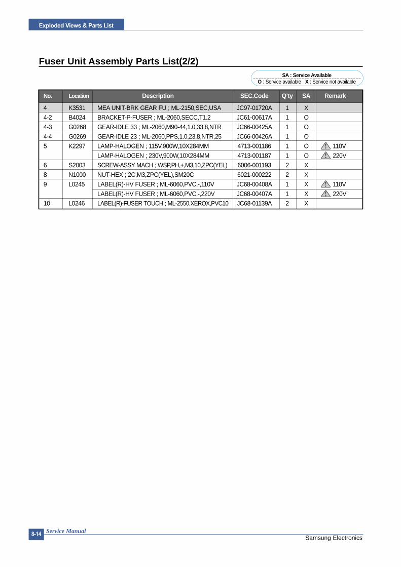
Samsung ElectronicsService Manual
Exploded Views & Parts List
8-14
Fuser Unit Assembly Parts List(2/2)
No. Location Description SEC.Code Q’ty SA Remark
4 K3531 MEA UNIT-BRK GEAR FU ; ML-2150,SEC,USA JC97-01720A 1 X
4-2 B4024 BRACKET-P-FUSER ; ML-2060,SECC,T1.2 JC61-00617A 1 O
4-3 G0268 GEAR-IDLE 33 ; ML-2060,M90-44,1.0,33,8,NTR JC66-00425A 1 O
4-4 G0269 GEAR-IDLE 23 ; ML-2060,PPS,1.0,23,8,NTR,25 JC66-00426A 1 O
5 K2297 LAMP-HALOGEN ; 115V,900W,10X284MM 4713-001186 1 O 110V
LAMP-HALOGEN ; 230V,900W,10X284MM 4713-001187 1 O 220V
6 S2003 SCREW-ASSY MACH ; WSP,PH,+,M3,10,ZPC(YEL) 6006-001193 2 X
8 N1000 NUT-HEX ; 2C,M3,ZPC(YEL),SM20C 6021-000222 2 X
9 L0245 LABEL(R)-HV FUSER ; ML-6060,PVC,-,110V JC68-00408A 1 X 110V
LABEL(R)-HV FUSER ; ML-6060,PVC,-,220V JC68-00407A 1 X 220V
10 L0246 LABEL(R)-FUSER TOUCH ; ML-2550,XEROX,PVC10 JC68-01139A 2 X
SA : Service AvailableO : Service available X : Service not available

Exploded Views & Parts List
Samsung ElectronicsService Manual 8-15
8.5 Main Driver Assembly
0
1
1525
3
17
4
6
7
8
9
10
16
1213
14
Harness-Main Motor
11
Main Driver Assembly Parts List
No. Location Description SEC.Code Q’ty SA Remark
0 M2098 ELA UNIT-MOTOR MAIN CAR 25 ; ML-2550,XEROX JC96-02725B 1 O
1 M2140 MOTOR DC-BLDC CARDINAL ; 50M8432030,1.7A JC31-00024A 1 O
2 B4029 BRACKET-P-MAIN ; ML-2060,SECC,1.6,163,123 JC61-00622A 1 O
3 P2057 GEAR-RDCN PICK_UP ; ML-2060,M90-44,0.8,63 JC66-00411A 1 O
4 P2056 GEAR-PICK_UP DRV ; ML-2060,SW-01,0.8,59,10 JC66-00412A 1 O
5 G0400 GEAR-RDCN RETARD ; ML-2060,SW-01,0.8,27/19 JC66-00410A 1 O
6 F6085 GEAR-RDCN FEED ; ML-2060,SW-01,0.8,33/23,1 JC66-00409A 1 O
7 G0339 GEAR-MP DRV ; ML-2060,M90-44,0.8,45,7.5,NT JC66-00413A 1 O
8 G0413 GEAR-REGI IDLE ; ML-2060,M90-44,0.8,29,15E JC66-00408A 1 O
9 G0399 GEAR-RDCN REGI ; ML-2060,SW-01,0.5/0.8,59 JC66-00407A 1 O
10 G0346 GEAR-OPC DRV INNER ; ML-2150,M90-44,0.5,53 JC66-00644A 1 O
11 W0002 WASHER-PLAIN ; NYLON,CUTTING,ID5,OD9,T0.5 6031-001255 2 O
12 O0012 GEAR-RDCN OPC ; ML-2060,M90-44,0.5,61/26,1 JC66-00405A 1 O
13 D3019 GEAR-DUPLEX IDLE ; ML-2060,M90-44,1.0,23,3 JC66-00415A 1 O
14 D3022 GEAR-RDCN DUPLEX ; ML-2060,SW-01,0.8/1.0,1 JC66-00414A 1 O
15 F1017 COM,FOOT-RUBBER ; CR70,BLK JC61-40001A 1 O
16 G0348 GEAR-OPC DRV OUTER ; ML-2150,M90-44,0.8,31 JC66-00645A 1 O
17 L0028 LABEL(P)-CAUTION MOTOR ; SF-5100,PVC,12*29 JC68-00261A 1 X
SA : Service AvailableO : Service available X : Service not available

Samsung ElectronicsService Manual
Exploded Views & Parts List
8-16
8.6 Exit Driver Assembly
0 4
1
2
Harness-Motor
3
4
5
6
6
89
1011
12
7
9
Parts List
No. Location Description SEC.Code Q’ty SA Remark
0 M2097 ELA UNIT-MOTOR EXIT CARDINAL2 ; ML-2550,XE JC96-02857A 1 O
1 M2153 MOTOR STEP-CARDINAL 2;M49SP-2NK,ML-2550 JC31-00028C 1 O
2 K4023 PMO-IMPELLER_DRV ; ML-6200,-,PC,BLK,V0 JC72-00825A 1 X
3 B4022 BRACKET-P-EXIT ; ML-2060,SECC,1.2,77,85 JC61-00623A 1 O
4 G0198 GEAR-DP,IDLE ; ML-165,POM(NW-02),WHT,M1,Z2 JC66-40911A 2 O
5 E4047 GEAR-RDCN EXIT ; ML-2060,M90-44,0.5/1.0,53 JC66-00419A 1 O
7 F4087 GEAR-FUSER IDLE ; ML-2060,SW-01,1.0,29,8,N JC66-00418A 1 O
8 E4045 GEAR-EXIT/U,ID ; ML-1605,POM,BLK JC66-40211B 1 O
10 F4098 GEAR-RDCN FUSER IN ; ML-2060,M90-44,0.5,79 JC66-00416A 1 O
11 C9033 GEAR-HUB CLUTCH ; SCX-5100,POM,M0.8,Z13 JC66-00340A 1 O
12 F4099 GEAR-RDCN FUSER OUT ; ML-2060,M90-44,1.0,2 JC66-00417A 1 O
SA : Service AvailableO : Service available X : Service not available

Exploded Views & Parts List
Samsung ElectronicsService Manual 8-17
8.7 Regi Assembly
12
12
3
4
5
4
18
16
1218
1212
6
7
21
20
17
810
9
15
11 13
14
0
Parts List
No. Location Description SEC.Code Q’ty SA Remark
0 K3171 ELA UNIT-REGI ; ML-2060A,SEC,220V JC96-02626A 1 O
1 G2080 GUIDE-P_REGI LOWER ; ML-2060,SECC,1.2 JC61-00674A 1 O
2 K4228 ROLLER-REGI LOWER L ; ML-2060,CR,13.6,BL JC66-00450A 1 X
3 S4129 SHAFT-REGI UPPER ; ML-2060,SUM,6 JC66-00446A 1 X
4 K4220 ROLLER-M_REGI IDLE S25 ; ML-2150,POM,11.9 JC66-00648A 2 O
5 K4221 ROLLER-M_REGI IDLE L25 ; ML-2150,POM,12.1 JC66-00647A 2 O
6 Z4109 SPRING-TS ; SUS304,-,PI0.45,D5.45,L19.8 6107-001160 1 O
7 S6005 PMO-ACTUATOR REGISHUTTER ; ML-2060,PET G/F JC72-00998A 1 O
8 G2081 GUIDE-P_REGI PLATE ; ML-2060,SECC,1.2 JC61-00670A 1 O
9 H4035 HOLDER-M-SENSOR ; ML-2060,HIPS,BLK JC61-00672A 1 O
10 K2483 PHOTO-INTERRUPTER ; TR,90%,150mW,DIP-4,BK 0604-001095 1 O
11 K2884 BUSH-M-ROLLER REGI L ; ML-2060,POM(M90-44) JC61-00668A 2 O
13 K2885 BUSH-M-ROLLER REGI U ; ML-2060,POM(M90-44) JC61-00669A 2 O
14 Z4110 SPRING-ES ; SWP-WPB,-,PI0.55,-,L25,N29 6107-001155 2 O
15 H1168 CBF HARNESS-MP EMPTY ; ML-2150,CBF,UL 1061 JC39-00256A 1 O
16 W0002 WASHER-PLAIN ; NYLON,CUTTING,ID5,OD9,T0.5 6031-001255 1 O
17 C1016 CAP-M-WIRE PTL UPPER ; ML-2060,POM,B JC67-00035A 1 O
18 A0003 CAP-M_BUSHING ACTUATOR ; ML-2060,POM JC67-00047A 2 O
19 C1017 CAP-P_BUSHING REGI LOWER;ML-2060,SUS,T0 JC67-00038A 2 O
20 M0248 PBA MAIN-PTL1 ; ML-2150,SEC,KOREA,PTL1 B'D JC92-01475A 1 X21 B5010 MEC- BRUSH ANTISTATIC ; ML-6060A,SEC,NTR JC75-00095A 1 O
SA : Service AvailableO : Service available X : Service not available

Samsung ElectronicsService Manual
Exploded Views & Parts List
8-18
8.8 SMPS Assembly
0
1
2-1
2
2-13
2-15
2-142-12
2-142-3
2-4
2-5
2-6
2-72-8
2-11
2-9
2-10
2-2
2-16

Exploded Views & Parts List
Samsung ElectronicsService Manual 8-19
SMPS Unit Parts List
No. Location Description SEC.Code Q’ty SA Remark
0 S7016 ELA HOU-SMPS_HVPS_V1(110V) ; ML-2550,SEC JC96-02779B 1 O 110V
ELA HOU-SMPS_HVPS_V2(220V) ; ML-2550,SEC JC96-02777B 1 O 220V
1 S7050 SMPS-V1_HVPS ; ML-2150,CARDINAL-V1,AC/DC JC44-00052A 1 O 110V
SMPS-V2_HVPS ; ML-2150,CARDINAL-V2,AC/DC JC44-00053A 1 O 220V
2 D3026 MEA UNIT-DUPLEX ; ML-2550,XEROX,USA,DUPLEX JC97-01714B 1 O
2-1 G2066 GUIDE-M-LEFT, DUP ; ML-2060,HIPS, HB,2.0,4 JC61-00664A 1 O
2-2 G2084 GUIDE-P-BOTTOM, DUP ; ML-2060,SECC,0.8,248 JC61-00661A 1 O
2-3 F6137 MEA UNIT-ROLLER FEED, DUP ; ML-2150,SEC JC97-01713A 1 X
2-4 G0456 ICT-STUD DRV GEAR, DUP ; ML-2060,SWCH10181 JC70-00327A 1 O
2-5 G0198 GEAR-DP,IDLE ; ML-165,POM(NW-02),WHT,M1,Z2 JC66-40911A 1 O
2-6 S4108 SHAFT-IDLE ROLL, DUP ; ML-2060,SUM24L,24,2 JC66-00444A 1 O
2-7 K4223 ROLLER-M-IDLE, DUP ; ML-2060,POM, SW01,8.0 JC66-00442A 1 O
2-8 K2702 SPRING-TS ; SUS304-WPB,-,PI0.4,D6.7 6107-001158 1 O
2-9 Z4110 SPRING-EMPTY ; ML-6000,SUS304-WPB,PI0.25 JC61-70965A 1 O
2-10 E6155 PMO-ACTUATOR FEED, DUP ; ML-2060,POM,BLK JC72-00997A 1 O
2-11 W0003 PCT-SILP WASHER ; SRP-350,PET,T0.5 JK72-00058A 1 X
2-12 G2098 ICT-STUD PAPER GUIDE, DP ; ML-2150,SUS 303 JC70-00457A 2 O
2-13 G2075 GUIDE-M-RIGHT, DUP ; ML-2060,ABS, V0,2.0,5 JC61-00662A 1 O
2-14 F6042 BUSH-M-FEED, DUP ; ML-2060,POM, SW01,4.1,7 JC61-00665A 2 O
2-15 K3929 GUIDE-P_SKEW, DUP ; ML-2150,SUS304,0.15,13 JC61-00787A 1 X
2-16 S5071 SHEET-GUIDE BOTTOM ; ML-2550,WEBSULER,T5 JC63-00297A 1 O
SA : Service AvailableO : Service available X : Service not available

Samsung ElectronicsService Manual
Exploded Views & Parts List
8-20
8.9 Cassette Assembly
19
19
20
20
1110
1212
11
8
11
13
12
11
14
7
23
24
22
21
1
27
9
26
1617
27
27
12
15
18
6
5
2
34

Exploded Views & Parts List
Samsung ElectronicsService Manual 8-21
Cassette Assembly Parts List
No. Location Description SEC.Code Q’ty SA Remark
0 K3096 ELA UNIT-CASSETTE(550) ; ML-2150,SEC,110 JC96-02845A 1 O
1 F2112 FRAME-M-CASSETTE ; ML-2060,HIPS,HB,BLACK JC61-00642A 1 O
2 G2062 GUIDE-M-HANDLE ; ML-2060,ABS,V0,IVOR JC61-00655A 1 O
3 L0209 LABEL(R)-CASSETTE ; ML-2060,SAMSUNG,TETRON JC68-01031A 1 X
4 G2064 GUIDE-M-INNER CST ; ML-2060,HIPS,HB JC61-00704A 1 O
5 H4028 HOLDER-M-INDICATOR ; ML-2060,ABS,BLK JC61-00639A 1 O
6 K3263 INDICATOR-M-EMPTY ; ML-2060,HIPS,-,RED,HB JC64-00041A 1 O
7 E5005 GUIDE-M-EXTENSION CST ; ML-2060,HIPS,HB JC61-00644A 1 O
8 G2264 GUIDE-P-SIDE,L ; ML-2060,SECC,T1.2 JC61-00647A 1 X
9 C1014 CAP-M-GUIDE SIDE,L ; ML-2060,ABS,BLK JC67-00037A 1 O
10 F0004 IPR-P-FINGER LEFT ; ML-2060,SPCC,T1.2 JC70-00325A 1 O
11 F0001 BUSH-M-FINGER,F ; ML-2060,POM(M90-44) JC61-00653A 4 O
12 W0002 WASHER-PLAIN ; NYLON,CUTTING,ID5,OD9,T0.5 6031-001255 4 O
13 G2265 GUIDE-P-SIDE,R ; ML-2060,SECC,T1.2 JC61-00649A 1 X
14 G2076 GUIDE-M-SIDE LOCK ; ML-2060,ABS,HB JC61-00645A 1 O
15 F0005 IPR-P-FINGER RIGHT ; ML-2060,SPCC,T1.2 JC70-00326A 1 O
16 G0369 GEAR-PINION ; SF4000,POM,WHT,M1,Z16 JG66-40003A 1 O
18 P5146 PLATE-P-KNOCK_UP ; ML-2060,SECC,T1.0,243 JC61-00651A 1 X
19 K4243 RPR-PAD CST ; ML-165,CORK,25.8*24.6,NTR JC73-10910A 2 O
21 G2073 GUIDE-M-REAR ; ML-2060,HIPS,HB,IVORY JC61-00646A 1 O
22 G2068 GUIDE-M-LOCK A ; ML-2150,ABS,HB,C750 JC61-00267B 1 O
23 K3429 KNOB-M-REAR ; ML-2060,ABS,IVORY JC64-00042A 1 O
24 Z4247 SPRING ETC-REMAIN ; ML-9400W,SUS304WPB,0.4 JC61-00414A 1 O
25 G2088 GUIDE-P-REAR PAPER CST ; ML-2060,SUS-301,0 JC61-00751A 1 O
26 G2071 GUIDE-M-PAPER SIZE ; ML-2060,POM,WHT JC61-00648A 1 O
28 K4264 STOPPER-GUIDE_SIDE ; ML-2150,CR V0,10.0 JC61-00842A 4 O
SA : Service AvailableO : Service available X : Service not available

Samsung ElectronicsService Manual
Exploded Views & Parts List
8-22
8.10 SCF Assembly
105
105
32
31
102
101
28
103
38
102
18-1
24
0
101
101
20
27
27
11
12
27
10-1104
104
10-2
10-3
10-4
10-5
101
109
4
26
26
4
56
6 6
1314
17 15 33
16
23
104
105
8
87
125
101
22
34
102
33 19
18
101
102
21
2918-2
18-3
18-4
18-5
18-6
2336
3535-1
35-3
35-235-4
101
37

Exploded Views & Parts List
Samsung ElectronicsService Manual 8-23
SCF Assembly Parts List(1/2)
No. Location Description SEC.Code Q’ty SA Remark
0 L1012 ELA UNIT-SCF ; ML-2150 JC96-02842B 1 X
1 S1031 FRAME-M-SCF ; ML-2060, JC61-00643A 1 O
2 P2051 MEA UNIT-PICK UP ASS'Y JC96-02683A 1 O
2-1 P2068 HOUSING-M-PICKUP ; ML- JC61-00636A 1 O
2-2 P2148 RUBBER-PICK UP ; ML-21 JC73-00127A 2 O
3 E5025 SPRING ETC-EXTENSION JC61-70950A 1 O
4 F6161 PMO-BUSHING FEED ; ML- JC72-00382B 2 O
5 P2153 SHAFT-M-PICK UP ; ML-2 JC66-00440A 1 O
6 S4068 PMO-BEARING SHAFT ; ML JC72-41191B 4 O
7 F6089 HOUSING-M-FEED ; ML-21 JC61-00637A 1 O
8 P2038 BEARING-PICK UP ; ML-8 JC66-10202A 2 O
9 G2065 GUIDE-M-INNER,SCF ; ML JC61-00650A 1 O
10 K3172 ELA UNIT-RETARD ; ML-2 JC96-02682A 1 O
11 S4116 SHAFT-M-COUPLING RET JC66-00441A 1 O
12 S4120 SHAFT-M-GEAR RETARD; JC66-00438A 1 O
13 P2059 GEAR-SCF PICK_UP CAM JC66-00534A 1 O
14 S8014 SOLENOID-MP;DLH-34L0 JC33-00013A 1 O
15 F6211 SHAFT-FEED SCF ; ML-20 JC66-00593A 1 O
16 C9049 MEP-CLUTCH FEED SCF; JC47-00009B 1 O
17 G0415 GEAR-REGI Z25 ; ML-215 JC66-00420A 1 O
18 M2101 ELA UNIT-MOTOR SCF ; M JC96-02858A 1 O
18-1 M2165 MOTOR STEP-SCF ; -,ML- JC31-00005E 1 O
18-2 S1009 BRACKET-P-SCF ; ML-206 JC61-00624A 1 O
18-3 G0413 GEAR-REGI IDLE ; ML-21 JC66-00408A 1 O
18-4 G0400 GEAR-RDCN RETARD ; ML- JC66-00410A 1 O
18-5 P2060 GEAR-SCF RDCN PICK_U JC66-00428A 1 O
18-6 F6087 GEAR-SCF RDCN FEED ; M JC66-00427A 1 O
19 F6094 IPR-GROUND SPRING_ F JC70-00464A 1 O
20 W3026 PHOTO-INTERRUPTER ; TR 0604-001095 1 O
21 M0416 PBA SUB-SCF ; ML-2060, JC92-01436A 1 O
22 H1227 CBF HARNESS-SCF ; ML-2 JC39-00248A 1 O
23 H1230 CBF HARNESS-SCF EMPT JC39-00250A 1 O
24 S1071 PMO-ACTUATOR EMPTY,S JC72-00992A 1 O
25 K3332 IPR-GROUND TOP ; ML-60 JC70-11028A 1 O
26 F1013 FOOT-ML80;ML-80,CR70 JC61-40001A 2 O
27 K2861 BAR-P_CROSS BOTTOM ; M JC71-00042A 3 O
28 S1011 COVER-M-LEFT SCF ; ML- JC63-00112A 1 O
29 S1013 COVER-M-RIGHT SCF ; ML JC63-00113A 1 O
30 D2010 COVER-M-DUMMY SCF ; ML JC63-00114A 1 O
31 H1231 CBF HARNESS-SCF GND; JC39-40608A 1 O
32 L5004 CBF HARNESS-LIU GND; JB39-00103A 1 O
33 H1182 CBF HARNESS-OPE ; SF30 JB39-40532A 1 O
34 C0029 BUSH-CABLE ; ML-2150,N JC61-00804A 1 O
SA : Service AvailableO : Service available X : Service not available

Samsung ElectronicsService Manual
Exploded Views & Parts List
8-24
SCF Assembly Parts List(2/2)
No. Location Description SEC.Code Q’ty SA Remark
35 K2953 ELA HOU-CST SENSOR H JC96-02127A 1 O
35-1 S3058 IPR-PLATE SENSOR ; ML- JC70-00192A 1 O
35-2 S3055 IPR-BRACKET SENSOR ; M JC70-00195A 1 O
35-3 M0301 PBA SUB-CASSETTE ; ML- JC92-01336A 1 X
36 H1234 CBF HARNESS-SCF PAPE JC39-00297A 1 O
37 M2053 CBF HARNESS-MOTOR ; ML JC39-00157A 1 O
38 G2069 GUIDE-M-PAPER PATH ;M JC61-00803A 1 O
SA : Service AvailableO : Service available X : Service not available

99
9-1Samsung Electronics
B LOCK DIAG R A M
Service Manual
9. Block Diagram
ACK* ,BU SY,SELECT ,ERROR,FAULT *
SELIN*ST ROBE*AUT OFD*
INI *
PD(0:7)

9-2
B LOCK DIAG R A M
Samsung ElectronicsService Manual

1100
10-1Samsung Electronics
CONNECTION DIAG R A M
Service Manual
10. Connection DiagramLS
U
CO
VER
OPE
NB
’D
PAN
EL
CO
VER
JOIN
T
CO
NN
EC
TOR
B’D
PTL
MA
IN-C
LUTC
H
SM
PS
/H
VP
S
CO
NTR
OLL
ERS
MP
S/
HV
PS
CO
NTR
OLL
ER
SUB
MO
TOR
LAM
P
INLE
TA
SS’Y
REG
I-CLU
TCH
3P
2P
EXIT
SEN
SO
R
1V
CC
2S
IGN
AL
3G
ND3P
TONE
R CA
RTRI
DGE
4P
1M
HV
2N
C
3N
C
4O
PC
GN
D
5N
C
6S
UPP
LY
7N
C
8D
EV
24P
SEN
SO
RB
’D
THER
MIS
TOR
JOIN
TB
’D
2P
1T
HER
M1
2T
HER
M2
1G
ND
2P
_RE
GI
3P
_EM
PTY
4V
CC4P
11P
1LS
UC
LK
2LR
EAD
Y*
3P
MO
TOR
*
4G
ND
524
V
63.
3V
7V
DO
-
8V
DO
+
9LD
_ON
*
10G
ND
115V
S
12nH
SYN
C
1G
ND
2C
AR
T_C
LK
3C
AR
T_D
ATA
43.
3V
5P
_EM
PTY
6P
_RE
GI
7TH
ER
M1
8TH
ER
M2
9P
_SIZ
E1
10P
_SIZ
E2
11P
_SIZ
E3
12P
1V
CC
23.
3V
3P
ANE
L_TX
4P
ANE
L_R
X
5P
ANE
L_R
ESE
T
6G
ND
6P 6P
124
V
224
V
324
VS
424
VS
5G
ND
65V
S
2P1
24
224
VS
MA
INM
OTO
R
4P
1P
A_1
2P
A_2
3P
B_1
4P
B_2
8P
124
VS
224
VS
3G
ND
4G
ND
5G
ND
6V
CC
7nS
TAR
T_ST
OP
8M
OTO
R_R
EAD
Y
9M
OTO
R_C
LK
2P
124
VS
2M
AIN
_CLU
T
3M
P_C
LUT
4R
EG
I_C
LUT
8P
5M
P_E
MPT
Y
63.
3V
7P
RO
_MF
8G
ND
MP
-CLU
TCH
REG
ISE
NS
OR
3P
1V
CC
2S
IGN
AL
3G
ND
MP
-EM
PTY
3P 2P 2P 3P
1N
C
224
V
3D
EV
_PW
M
424
V
5M
HV
_PW
M
624
V
7G
ND
8G
ND
9M
HV
_REA
D
10G
ND
11T
HV
_RE
AD
123.
3V
13T
HV
_EN
143.
3V
15T
HV
_PW
M
16G
ND
1724
VS
18G
ND
19V
CC
20V
CC
21N
C
22P
_EX
IT
23P
_DU
PLE
X
24F
US
ER
13.
3V
2S
CF
_ST
S
3S
CF
_CM
D
4S
CF
_CL
K
5S
CF
_RD
Y
624
V
7G
ND
8G
ND
SC
F8P
FAN
3P

10-2
CONNECTION DIAG R A M
Samsung ElectronicsService Manual

11. Schematic Diagrams
11-1 Main Circuit Diagram(1/9)
11-1

Main Circuit Diagram(2/9)
11-2
Schematic Diagrams

Main Circuit Diagram(3/9)
11-3
Schematic Diagrams

Main Circuit Diagram(4/9)
11-4
Schematic Diagrams

Main Circuit Diagram(5/9)
11-5
Schematic Diagrams

Main Circuit Diagram(6/9)
11-6
Schematic Diagrams

Main Circuit Diagram(7/90)
11-7
Schematic Diagrams

Main Circuit Diagram(8/9)
11-8
Schematic Diagrams

Main Circuit Diagram(9/9)
11-9
Schematic Diagrams

11-10
Schematic Diagrams
R50
95.
6K
DE
V50
K
R51
330
KF
R51
61/
2W15
MF
R51
010
0K
Q50
4C
2316
Q50
3C
945C
-YZ
D50
22.
7VB
R51
147
0
ZD
501
2.7V
R50
810
K
R50
410
K
R50
333
0KF
C50
447
2
Q50
1A
708-
Y
D50
44K
V
D50
3D
1NL2
0U
C50
7M
Y-2A
103
C50
510
4
R51
5M
F1/
2W50
K
R51
7M
F1/
2W50
K
ZD
503
180V
T50
1R
550
1/2W
1.8M
C50
93K
V47
1
C55
02K
V10
1
R51
41/
2W10
MF
R51
21/
4W10
R40
95.
6K
R40
810
K
R41
010
0K
R41
61/
2W10
0M
ZD
403
100V
D40
21N
4148
C40
333
1
C40
447
2R
403
1.5M
R40
410
K
C40
210
2
R40
147
KR
402
22K
C40
147
3
D40
44K
V
C40
510
4R
411
470
Q40
3C
945C
-YR
412
1/4W
5
Q40
4C
2316
ZD
402
2.7V
BD
403
D1N
L20U
D40
11N
4148
ZD
401
2.7V
Q40
1A
708-
Y
R41
5M
F1/
2W10
0K
T40
1
24V
1
5V1
D50
11N
4148
R50
147
KR
502
22K
5V1
D45
51N
4148
R46
0R
D1/
8W1.
5KC
456
MY
2A47
3
1312
IC10
3/F
7407 1
2
MH
V_R
EA
D50
KR
458
RS
1/8W
30K
F
C45
8M
Y2A
473
D45
61N
4148
+3
-2
1
8 4
R50
05.
6K
5V1
R40
05.
6K
C50
147
3
INO
UT
GND
IC10
1K
A78
05
+12
-13
14
IC10
4/D
KA
324
+5
-6
7
C40
6C
E-1
03 C40
7 103
C45
7C
E-1
03
C50
6C
E-1
03
R41
41/
2W60
MF
R46
1R
D1/
8W2.
2KJ
C10
235
V47
uF
C45
91K
V22
1
R45
01/
2W56
0K
5V1C40
93K
V47
1
C41
0C
E-1
04C46
047
uF
R41
330
KF
MH
V20
K
R41
710
0J
5V1
C50
847
uF5V1
Q10
2B
1151
-Y
R10
13K
J R10
21K
JQ
101
C10
08
R10
410
0J
R10
31W
1KJ
C50
210
2
C50
368
1D
502
1N41
48
ZD
404
3.3B
R51
810
0J
5V1
C10
1
35V
47uF
24V
1
BIA
S
MH
V
MH
V_R
EA
D
5V1
24V
S
3.3V
24V
1
HV
PS
_+5V
>>
BIA
S-s
en>
>D
EV
>>
SU
PP
LY
>>
MH
V-s
en
>>
MH
V-s
en>
>O
PC
>>
MH
V
>>
BIA
S-s
en
CN
1-#4
BIA
S P
WM
MH
V P
WM
CN
1-#6
MH
V R
EA
DC
N1-
#10
4 2 5 1
4 2 156 7
6 7
11-2 HVPS Circuit Diagram(1/2)

11-11
Schematic Diagrams
R30
2R
D1/
8W47
0KC
302
CE
-103
R21
3B
LR1/
2W30
M
R20
810
K
ZD
201
2.7V
B
Q20
3C
2383
D20
2D
1NL2
0U
D20
3D
1NL2
0U
ZD
301
2.7V
B
D30
1D
1NL2
0U
Q30
2C
2383
C30
43K
V15
1
R30
5M
GR
1/2W
50M
C30
5C
E-1
04D
304
1N41
48
Q20
294
5C-Y
C20
8M
Y-2A
681
R21
2R
D1/
2W10
0K
D30
31N
4148
D30
24K
V
24V
1 24V
1
R30
81.
5K
IND
EX
50K
C20
7C
E-1
03R
209
100K
5V1
D20
11N
4148
C20
4C
E-1
03
R20
522
KR
204
47K
C20
210
2
T30
1
C20
6M
Y-2A
104
C30
310
3
TH
V50
K
R20
616
.2K
F
C20
368
1
T20
1
R30
6R
S1/
8W10
0KF
C30
1M
Y2A
104J
R30
41/
4W4.
7
C30
6M
Y2A
473J
D30
51N
4148
R30
3R
D1/
8W47
0
+5
-6
7
IC10
5/B
5V1
R20
310
0
R20
243
0
Q20
1A
708-
Y
R30
010
0
R30
143
0
Q30
0A
708-
Y
R21
11/
4W4.
7J
Q30
194
5C-Y
C20
1M
Y2A
473
R20
1R
-/6W
2KJ
+3
-2
1
11 4
IC10
5/A
KA
358
R21
05.
6KJ
5V1
R31
12.
2k
R31
01K
D20
4
6KV
C21
0
6KV
221
C21
16K
V22
1
C20
96K
V22
1 D20
56K
VD
206
6KV
C20
5M
Y-2A
471
R20
733
0KF
C30
7M
Y2A
473J
ZD
302
3.3B
VA
201
7D43
1K
VA
202
7D43
1K
C21
32K
V22
1
R30
7
RS
1/8W
330K
F
TH
V_R
EA
D
TH
V
TH
V
>>
TH
V-s
en
TH
V R
EA
DC
N1-
#12
>>
TH
V
>>
TH
V-s
en
4 2 5 1 4 2 5 1
6 7
+5V
1
CN
1-#1
6T
HV
PW
M CN
1-#1
4T
HV
-E
A
76
HVPS Circuit Diagram(220V)

11-12
Schematic Diagrams
BD
1D
5SB
A60
CN
1
F2
125V
5A
C6
200V
560u
F
R4
3W47
KJ
C7
630V
103K
C22
50V
104J
D5
200V
20A
T1/
A
I1
O2
G3
C4
IC4
KA
378R
33
D4
C16
C17
50V
104J
C25
R25 R26
C26
TH
2
TH
110
D-1
5
B3,
B4
L1
3.3V
OP
1
C33
50V
104J
R40
100J
R38
100J
CN
4
5301
4-03
10
D1
F1
125V
8A R1
LF1
C1
474
C3
C4
LF2
AR
1
CN
2
L2 AY-
70H
C14
474
IC6
TLP
3061
F
IC5 Q
2C
1008
-Y
R33
RD
1/4W
1.5K
J
R34
1KJ
R17
15K
J
N.C1
SOFT START2
FEED BACK3
I-S
EN
SO
R4
GATE5
VCC6
GND7
N.C
8
IC1
IC-I
CE
2XS
01
D2
1N41
48R
64.
7J
R5
82J
D3
B2
Q1
11N
60
C34
B1
1
4 3
2
PC
1 IC2
KA
431Z
C20
C19
C9
472M
AA
C13
35V
33uF
R3
1W47
KJ
R2
1W47
KJ
C31
50V
104J
R31
1W10
0J
R32
1W18
0J
R30
1W47
J
C30
630V
333
GA
P2
C15
R20
,24,
27,1
42W
2KJ*
4
C21
R12
2.49
KF
R21
47K
F
D7
D6
60V
3AC
24
I1
O2
G3
C4
IC3
KA
278R
05
C23
TN
R1
10D
221K
GA
P1
AR
2
R10
1/4W
22J R
1510
KJ
C10
683J
C5
683J
C8
222J
R13
120J
R7
1W0.
25J
R39
15K
J
R8
2KJ
R11
22.6
KF
C35
68pF
+24
V3.
0A
+3.
3V1.
5A
GN
D
GN
D
24P
in24
PIN
+24
VS
2
FU
SE
R_O
N
IC4_
IN
IC4_
IN
HV
PS
__+
5V
+5V
0.7A
GN
D
2
CN
3-1,
3,5
4
10,1
1,12
9
15
8 7
NO
MA
RK
ING
RE
SIS
TO
R 1
/8W
-J(5
%)
CN
3-11
,13
CN
3-15
,17
10,1
1,12
CN
3-7,
9
DU
PLE
X S
EN
SO
RE
XIT
SE
NS
OR
FU
SIB
LE
CN
3-9
CN
3-10
FU
SIB
LE
14
10,1
1,12
13
CN
3-11
,13
CN
3-15
,17
PC
1
11-3 SMPS Circuit Diagram(110V)

BD
1D
5SB
A60
CN
1
F2
250V
3.15
A
C6
400V
270u
F
R4
3W47
KJ
C22
50V
104J
D5
200V
20A
T1/
A
I1
O2
G3
C4
IC4
KA
378R
33
D4
C16
C17
50V
104J
C25
R25 R26
C26
TH
2
TH
110
D-1
3
B3,
B4
L1
3.3V
OP
1
C33
50V
104J
R40
100J
R38
100J
CN
4
5301
4-03
10
D1
F1
250V
5A R1
LF1
C1
474
C3
C4
LF2
AR
1
CN
2
L2 AY-
70H
C14
474
IC6
TLP
3061
F
IC5 Q
2C
1008
-Y
R33
RD
1/4W
1.5K
J
R34
1KJ
R17
15K
J
N.C1
SOFT START2
FEED BACK3
I-S
EN
SO
R4
GATE 5
VCC 6
GND7N
.C8
IC1
IC-I
CE
2XS
01
D2
1N41
48R
64.
7J
R5
82J
D3
B2
Q1
08N
80
C34
B1
1
4 3
2
PC
1 IC2
KA
431Z
C20
C19
C9
472M
AA
C13
35V
33uF
R3
1W12
0KJ
R2
1W12
0KJ
C31
50V
104J
R31
1W22
J
R32
1W18
0J
R30
1W47
J
C30
630V
333
GA
P2
C15
R20
,24,
27,1
42W
2KJ*
4
C21
R12
2.49
KF
R21
47K
F
D7
D6
60V
3AC
24
I1
O2
G3
C4
IC3
KA
278R
05
C23
TN
R1
10D
561K
GA
P1
AR
2
R10
1/4W
22J R
1510
KJ
C10
683J
C5
683J
C8
222J
R13
330J
R7
1W0.
45J
R39
15K
J
R8
2KJ
R11
22.6
KF
C7
630V
103K
C35
68pF
+24
V3.
0A
+3.
3V1.
5A
GN
D
GN
D
24P
in24
PIN
+24
VS
2
FU
SE
R_O
N
IC4_
IN
IC4_
IN
HV
PS
__+
5V
+5V
0.7A
GN
D
2
CN
3-1,
3,5
4
10,1
1,12
9
15
8 7
NO
MA
RK
ING
RE
SIS
TO
R 1
/8W
-J(5
%)
CN
3-11
,13
CN
3-15
,17
10,1
1,12
CN
3-7,
9
DU
PLE
X S
EN
SO
RE
XIT
SE
NS
OR
FU
SIB
LE
CN
3-9
CN
3-10
FU
SIB
LE
14
10,1
1,12
13
CN
3-11
,13
CN
3-15
,17
PC
1
11-13
Schematic Diagrams
SMPS Circuit Diagram(220V)

11-14
Schematic Diagrams
BD
1D
5SB
A60
CN
1
F2
250V
3.15
A
C6
450V
270u
F
R4
3W47
KJ
C7
630V
103K
C22
50V
104J
D5
200V
20A
T1/
A
I1
O2
G3
C4
IC4
KA
378R
33
D4
C16
C17
50V
104J
C25
R25 R26
C26
TH
2
TH
110
D-1
3
B3,
B4
L1
3.3V
OP
1
C33
50V
104J
R40
100J
R38
100J
CN
4
5301
4-03
10
D1
F1
250V
5A R1
LF1
C1
474
C3
C4
LF2
AR
1
CN
2
L2 AY-
70H
C14
474
IC6
TLP
3061
F
IC5 Q
2C
1008
-Y
R33
RD
1/4W
1.5K
J
R34
1KJ
R17
15K
J
N.C1
SOFT START2
FEED BACK3
I-S
EN
SO
R4
GATE 5
VCC 6
GND7N
.C8
IC1
IC-I
CE
2XS
01
D2
1N41
48R
64.
7J
R5
82J
D3
B2
Q1
08N
80
C34
B1
1
4 3
2
PC
1 IC2
KA
431Z
C20
C19
C9
472M
AA
C13
35V
33uF
R3
1W12
0KJ
R2
1W12
0KJ
C31
50V
104J
R31
1W22
J
R32
1W18
0J
R30
1W47
J
C30
630V
333
GA
P2
C15
R20
,24,
27,1
42W
2KJ*
4
C21
R12
2.49
KF
R21
47K
F
D7
D6
60V
3AC
24
I1
O2
G3
C4
IC3
KA
278R
05
C23
TN
R1
10D
561K
GA
P1
AR
2
R10
1/4W
22J R
1510
KJ
C10
683J
C5
683J
C8
222J
R13
330J
R7
1W0.
45J
R39
15K
J
R8
2KJ
R11
22.6
KF
C35
68pF
+24
V3.
0A
+3.
3V1.
5A
GN
D
GN
D
24P
in24
PIN
+24
VS
2
FU
SE
R_O
N
IC4_
IN
IC4_
IN
HV
PS
__+
5V
+5V
0.7A
GN
D
2
CN
3-1,
3,5
4
10,1
1,12
9
15
8 7
NO
MA
RK
ING
RE
SIS
TO
R 1
/8W
-J(5
%)
CN
3-11
,13
CN
3-15
,17
10,1
1,12
CN
3-7,
9
DU
PLE
X S
EN
SO
RE
XIT
SE
NS
OR
FU
SIB
LE
CN
3-9
CN
3-10
FU
SIB
LE
14
10,1
1,12
13
CN
3-11
,13
CN
3-15
,17
PC
1
SMPS Circuit Diagram(220V for China)

11-15
Schematic Diagrams
11-3 Network Card Circuit Diagram(1/5)
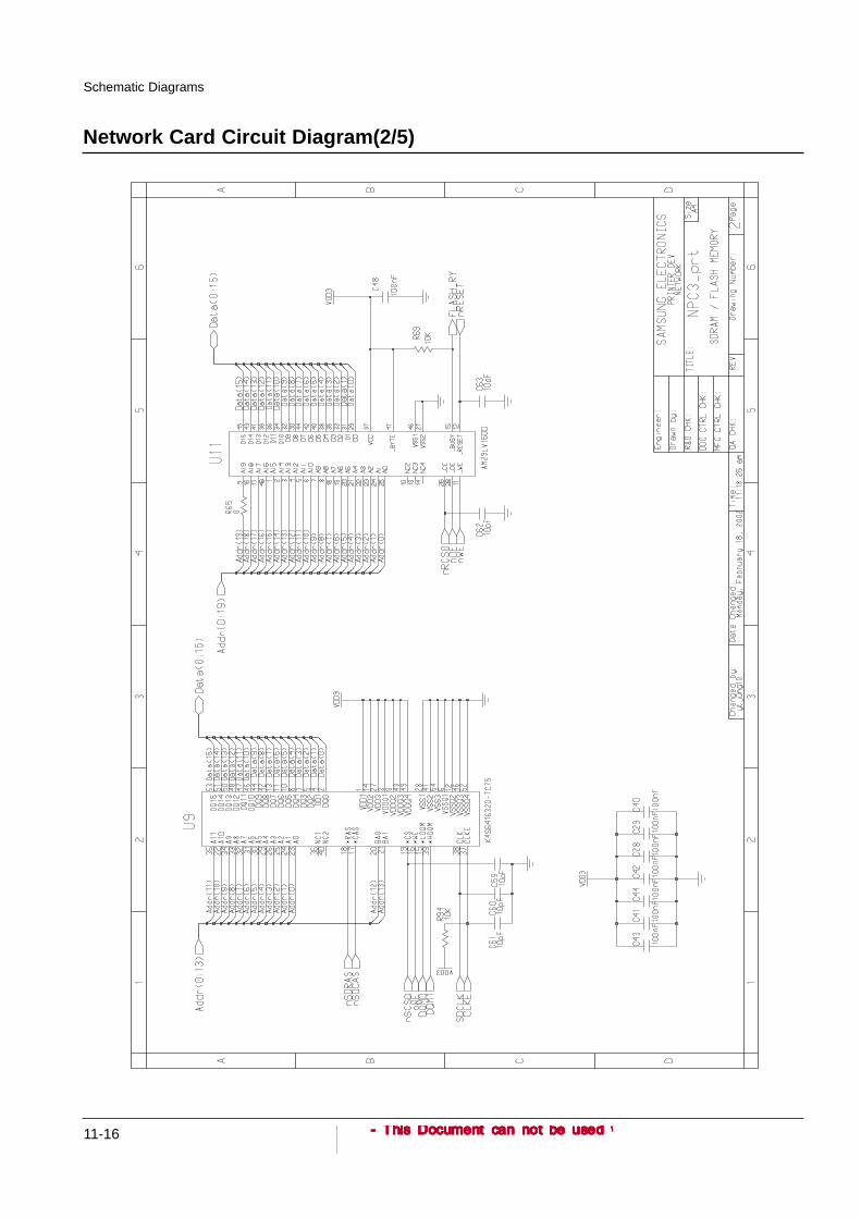
11-16
Schematic Diagrams
Network Card Circuit Diagram(2/5)

11-17
Schematic Diagrams
PLL OFF
DEBUG
NORMAL
. . XP I/F
IEEE1284
USB Disable
1 . .
ML-2152W ONLY
.
0 1
Addr19
Addr20
Addr21
Addr22
0 1
8BIT
16BIT
EDO DRAM
SDRAM
16BIT
SDRAM
Addr17
.
0 1
PLL ON
USB Enable
PLL ON
1 0
XP I/F
USB Enable
Addr18
0NORMAL
1 0
Network Card Circuit Diagram(3/5)

11-18
Schematic Diagrams
Network Card Circuit Diagram(4/5)

11-19
Schematic Diagrams
Network Card Circuit Diagram(5/5)

11-20
Schematic Diagrams
11-4 SCF PBA Circuit Diagram(1/2)

11-21
Schematic Diagrams
SCF PBA Circuit Diagram(2/2)

11-22
Schematic Diagrams
11-5 RAM DIMM Circuit Diagram(1/2)

11-23
Schematic Diagrams
RAM DIMM Circuit Diagram(2/2)

11-24
Schematic Diagrams
11-6 Panel PBA Circuit Diagram

11-7 PS3 ROM Circuit Diagram
11-25
Schematic Diagrams

11-26
Schematic Diagrams
11-8 Connector PBA Circuit Diagram
11-9 Cover Open Sensor Circuit Diagram

11-27
Schematic Diagrams
11-11 Exit Sensor Circuit Diagram
11-10 Enpty Sensor Circuit Diagram

11-28
Schematic Diagrams
11-12 OPC PBA Circuit Diagram
11-13 Toner PBA Circuit Diagram

11-29
Schematic Diagrams
11-14 Zener PBA Circuit Diagram

© Samsung Electronics Co.,Ltd. April 2003Printed in Korea.
VERSION NO. : 1.00 CODE : JC-0089A
This service manual is also provided on the web, the ITSELF system f Samsung Electronics Co., Ltd.
http://itself.sec.samsung.co.kr

Copyright(c) 2003.04