miter saw - images-na.ssl-images-amazon.com · 3 8. don’t force tool. it will do the job bet-ter...
TRANSCRIPT

I N S T R U C T I O N M A N U A L
WARNING:For your personal safety, READ and UNDERSTAND before using.SAVE THESE INSTRUCTIONS FOR FUTURE REFERENCE.
w w w. m a k i t a t o o l s . c o m
Miter SawEquipped with Electric Blade Brake355 mm (14”)MODEL LS1440
DOUBLEINSULATION

2
SPECIFICATIONSBlade diameter : ............................................................................................. 355 mm (14”)
Hole diameter : ................................................................25 mm (31/32”) and 25.4 mm (1”)
Max. Miter angle : ...................................................................................Left 45° , Right 45°
Max. Cutting capacities (H x W)
No load speed (RPM) : ........................................................................................ 3,200/min.
Dimensions (L x W x H) : .......................530 mm x440 mm x 610 mm (21” x 17-1/4” x 24”)
Net weight : ..................................................................................................... 30 kg (66 lbs)
• Manufacturer reserves the right to change specifications without notice.
• Specifications may differ from country to country.
For Your Own Safety Read Instruction Manual Before Operating Tool Save it for future reference GENERAL SAFETY PRECAUTIONS USA007-1
(For All Tools)1. KNOW YOUR POWER TOOL. Read the
owner’s manual carefully. Learn the tool’sapplications and limitations, as well as thespecific potential hazards peculiar to it.
2. KEEP GUARDS IN PLACE and in workingorder.
3. REMOVE ADJUSTING KEYS ANDWRENCHES. Form habit of checking tosee that keys and adjusting wrenches areremoved from tool before turning it on.
4. KEEP WORK AREA CLEAN. Clutteredareas and benches invite accidents.
5. DON’T USE IN DANGEROUS ENVIRON-MENT. Don’t use power tools in damp orwet locations, or expose them to rain.Keep work area well lighted. Don’t usetool in presence of flammable liquids orgases.
6. KEEP CHILDREN AWAY. All visitorsshould be kept safe distance from workarea.
7. MAKE WORKSHOP KID PROOF with pad-locks, master switches, or by removingstarter keys.
Miter angle
0° 45° (left and right)
122 mm x 152 mm(4-3/4” x 6”)
122 mm x 115 mm(4-3/4” x 4-1/2”)
3
8. DON’T FORCE TOOL. It will do the job bet-ter and safer at the rate for which it wasdesigned.
9. USE RIGHT TOOL. Don’t force tool orattachment to do a job for which it was notdesigned.
10. WEAR PROPER APPAREL. Do not wearloose clothing, gloves, neckties, rings,bracelets, or other jewelry which may getcaught in moving parts. Nonslip footwearis recommended. Wear protective haircovering to contain long hair.
11. ALWAYS USE SAFETY GLASSES. Alsouse face or dust mask if cutting operationis dusty. Everyday eyeglasses only haveimpact resistant lenses, they are NOTsafety glasses.
12. SECURE WORK. Use clamps or a vise tohold work when practical. It’s safer thanusing your hand and it frees both hands tooperate tool.
13. DON’T OVERREACH. Keep proper footingand balance at all times.
14. MAINTAIN TOOLS WITH CARE. Keep toolssharp and clean for best and safest perfor-mance. Follow instructions for lubricatingand changing accessories.
15. DISCONNECT TOOLS before servicing;when changing accessories such asblades, bits, cutters, and the like.
16. REDUCE THE RISK OF UNINTENTIONALSTARTING. Make sure switch is in offposition before plugging in.
17. USE RECOMMENDED ACCESSORIES.Consult the owner’s manual for recom-mended accessories. The use of improperaccessories may cause risk of injury topersons.
18. NEVER STAND ON TOOL. Serious injurycould occur if the tool is tipped or if thecutting tool is unintentionally contacted.
19. CHECK DAMAGED PARTS. Before furtheruse of the tool, a guard or other part thatis damaged should be carefully checkedto determine that it will operate properlyand perform its intended function - checkfor alignment of moving parts, binding ofmoving parts, breakage of parts, mount-ing, and any other conditions that mayaffect its operation. A guard or other partthat is damaged should be properlyrepaired or replaced.
20. DIRECTION OF FEED. Feed work into ablade or cutter against the direction ofrotation of the blade or cutter only.
21. NEVER LEAVE TOOL RUNNING UNAT-TENDED. TURN POWER OFF. Don’t leavetool until it comes to a complete stop.
22. REPLACEMENT PARTS. When servicinguse only identical replacement parts.
23. POLARIZED PLUGS. To reduce the risk ofelectric shock, this equipment has apolarized plug (one blade is wider thanthe other). This plug will fit in a polarizedoutlet only one way. If the plug does not fitfully in the outlet, reverse the plug. If itstill does not fit, contact a qualified elec-trician to install the proper outlet. Do notchange the plug in any way.
VOLTAGE WARNING: Before connecting the tool to a power source (receptacle, outlet, etc.)be sure the voltage supplied is the same as that specified on the nameplate of the tool. Apower source with voltage greater than that specified for the tool can result in SERIOUSINJURY to the user - as well as damage to the tool. If in doubt, DO NOT PLUG IN THETOOL. Using a power source with voltage less than the nameplate rating is harmful to themotor.

4
USE PROPER EXTENSION CORD. Make sure your extension cord is in good condition.When using an extension cord, be sure to use one heavy enough to carry the current yourproduct will draw. An undersized cord will cause a drop in line voltage resulting in loss ofpower and overheating. Table 1 shows the correct size to use depending on cord length andnameplate ampere rating. If in doubt, use the next heavier gage. The smaller the gage num-ber, the heavier the cord.
ADDITIONAL SAFETY RULES USB037-2
DO NOT let comfort or familiarity with product (gained fromrepeated use) replace strict adherence to miter saw safety rules.If you use this tool unsafely or incorrectly, you can suffer seri-ous personal injury.1. Wear eye protection.
2. Keep hands out of path of saw blade.Avoid contact with any coasting blade. Itcan still cause severe injury.
3. Do not operate saw without guards inplace. Check blade guard for proper clos-ing before each use. Do not operate saw ifblade guard does not move freely andclose instantly. Never clamp or tie theblade guard into the open position.
4. Do not perform any operation freehand.The workpiece must be secured firmlyagainst the turn base and guide fence witha vise during all operations. Never useyour hand to secure the workpiece.
5. Never reach around saw blade.
6. Turn off tool and wait for saw blade tostop before moving workpiece or chang-ing settings.
7. Unplug tool before changing blade or ser-vicing.
8. Always secure all moving portions beforecarrying the tool.
9. Do not use the tool in the presence offlammable liquids or gases.
10. Check the blade carefully for cracks ordamage before operation. Replacecracked or damaged blade immediately.Gum and wood pitch hardened on bladesslows saw and increases potential forkickback. Keep blade clean by first remov-ing it from tool, then cleaning it with gumand pitch remover, hot water or kerosene.Never use gasoline to clean blade.
Table 1: Minimum gage for cord
Ampere RatingVolts Total length of cord in feet120 V 25 ft. 50 ft. 100 ft. 150 ft.
More Than Not More Than AWG
0 6 18 16 16 146 10 18 16 14 12
10 12 16 16 14 1212 16 14 12 Not Recommended
5
11. Use only flanges specified for this tool.
12. Be careful not to damage the arbor,flanges (especially the installing surface)or bolt. Damage to these parts couldresult in blade breakage.
13. Make sure that the turn base is properlysecured so it will not move during opera-tion. Use the holes in the base to fastenthe saw to a stable work platform orbench. NEVER use tool where operatorpositioning would be awkward.
14. For your safety, remove the chips, smallpieces, etc. from the table top before oper-ation.
15. Avoid cutting nails. Inspect for andremove all nails from the workpiece beforeoperation.
16. Make sure the shaft lock is releasedbefore the switch is turned on.
17. Be sure that the blade does not contactthe turn base in the lowest position.
18. Hold the handle firmly. Be aware that thesaw moves up or down slightly duringstart-up and stopping.
19. Make sure the blade is not contacting theworkpiece before the switch is turned on.
20. Before using the tool on an actual work-piece, let it run for a while. Watch for vibra-tion or wobbling that could indicate poorinstallation or a poorly balanced blade.
21. Wait until the blade attains full speedbefore cutting.
22. Stop operation immediately if you noticeanything abnormal.
23. Do not attempt to lock the trigger in the onposition.
24. Be alert at all times, especially duringrepetitive, monotonous operations. Donot be lulled into a false sense of security.Blades are extremely unforgiving.
25. Always use accessories recommended inthis manual. Use of improper accessoriessuch as abrasive wheels may cause aninjury.
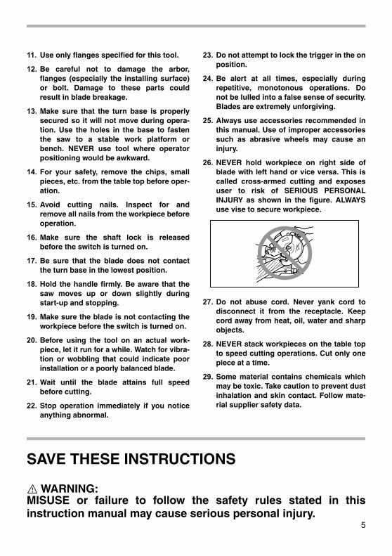
26. NEVER hold workpiece on right side ofblade with left hand or vice versa. This iscalled cross-armed cutting and exposesuser to risk of SERIOUS PERSONALINJURY as shown in the figure. ALWAYSuse vise to secure workpiece.
27. Do not abuse cord. Never yank cord todisconnect it from the receptacle. Keepcord away from heat, oil, water and sharpobjects.
28. NEVER stack workpieces on the table topto speed cutting operations. Cut only onepiece at a time.
29. Some material contains chemicals whichmay be toxic. Take caution to prevent dustinhalation and skin contact. Follow mate-rial supplier safety data.
SAVE THESE INSTRUCTIONS
WARNING:MISUSE or failure to follow the safety rules stated in thisinstruction manual may cause serious personal injury.
6
INSTALLATION
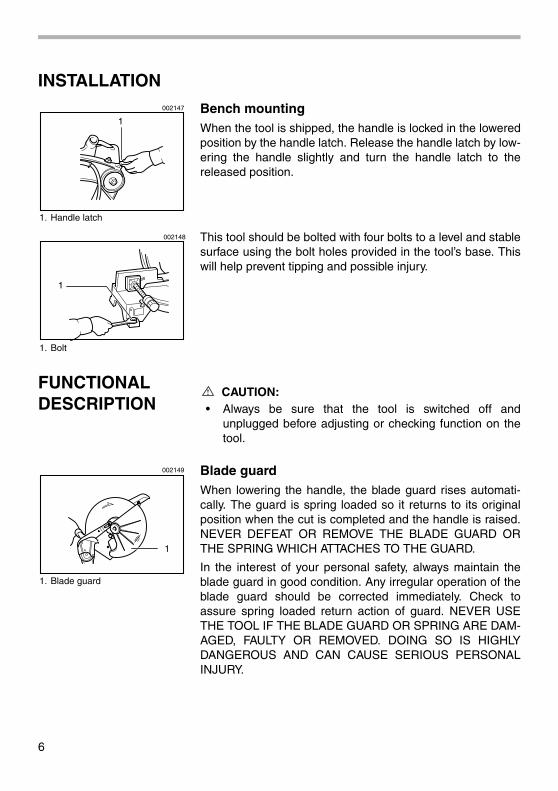
Bench mountingWhen the tool is shipped, the handle is locked in the loweredposition by the handle latch. Release the handle latch by low-ering the handle slightly and turn the handle latch to thereleased position.
This tool should be bolted with four bolts to a level and stablesurface using the bolt holes provided in the tool’s base. Thiswill help prevent tipping and possible injury.
FUNCTIONAL DESCRIPTION
CAUTION:• Always be sure that the tool is switched off and
unplugged before adjusting or checking function on thetool.
Blade guardWhen lowering the handle, the blade guard rises automati-cally. The guard is spring loaded so it returns to its originalposition when the cut is completed and the handle is raised.NEVER DEFEAT OR REMOVE THE BLADE GUARD ORTHE SPRING WHICH ATTACHES TO THE GUARD.
In the interest of your personal safety, always maintain theblade guard in good condition. Any irregular operation of theblade guard should be corrected immediately. Check toassure spring loaded return action of guard. NEVER USETHE TOOL IF THE BLADE GUARD OR SPRING ARE DAM-AGED, FAULTY OR REMOVED. DOING SO IS HIGHLYDANGEROUS AND CAN CAUSE SERIOUS PERSONALINJURY.
1. Handle latch
1
002147
1. Bolt
1
002148
1. Blade guard
1
002149

7
If the see-through blade guard becomes dirty, or sawdustadheres to it in such a way that the blade is no longer easilyvisible, unplug the saw and clean the guard carefully with adamp cloth. Do not use solvents or any petroleum-basedcleaners on the plastic guard.
If the blade guard is especially dirty and vision through theguard is impaired, use the supplied socket wrench to loosenthe hex bolt holding the center cover. Loosen the hex bolt byturning it counterclockwise and raise the blade guard andcenter cover. With the blade guard so positioned, cleaningcan be more completely and efficiently accomplished. Whencleaning is complete, reverse procedure above and securebolt. Do not remove spring holding blade guard. If guardbecomes discolored through age or UV light exposure, con-tact a Makita service center for a new guard. DO NOTDEFEAT OR REMOVE GUARD.
Kerf boardThis tool is provided with the kerf board in the turn base tominimize tearing on the exit side of a cut. If the kerf groovehas not yet been cut in the kerf board by the factory, youshould cut the groove before actually using the tool to cut aworkpiece. Switch on the tool and lower the blade gently tocut a groove in the kerf board.
Maintaining maximum cutting capacityThis tool is factory adjusted to provide the maximum cuttingcapacity for a 355 mm (14”) saw blade.
When installing a new blade, always check the lower limitposition of the blade and if necessary, adjust it as follows:
First, unplug the tool. Lower the handle completely. Loosenthe hex nut at the rear of the gear housing. Use a screwdriverto turn the adjusting bolt until the periphery of the bladeextends slightly below the top surface of the turn base at thepoint where the front face of the guide fence meets the topsurface of the turn base.
1. Blade guard
1
001782
1. Turn base2. Kerf board
1 2
002150
1. Gear housing2. Hex nut3. Adjusting bolt
1
23
002151

8
With the tool unplugged, rotate the blade by hand while hold-ing the handle all the way down to be sure that the bladedoes not contact any part of the lower base. Re-adjustslightly, if necessary.
After adjusting, tighten the hex nut with the wrench whilecarefully holding the adjusting bolt in position with the screw-driver.
CAUTION:• After installing a new blade, always be sure that the
blade does not contact any part of the lower base whenthe handle is lowered completely. Always do this with thetool unplugged.
Adjusting the miter angleLoosen the grip by turning counterclockwise. Turn the turnbase while pressing down the lock lever. When you havemoved the grip to the position where the pointer points to thedesired angle on the miter scale, securely tighten the gripclockwise.
CAUTION:• When turning the turn base, be sure to raise the handle
fully.
• After changing the miter angle, always secure the turnbase by tightening the grip firmly.
Fence plateThe fence plate is designed to prevent smaller cutting scrapsfrom jamming inside the blade case. The fence plate movesright or left automatically as the turn base is rotated.
Switch action
CAUTION:• Before plugging in the tool, always check to see that the
switch trigger actuates properly and returns to the “OFF”position when released.
• When not using the tool, remove the lock-off button andstore it in a secure place. This prevents unauthorizedoperation.
• Do not pull the switch trigger hard without pressing in thelock-off button. This can cause switch breakage.
1. Top surface ot turn base2. Periphery of blade3. Guide fence
21
3
001540
1. Pointer2. Latch spring3. Miter scale4. Grip
12
4
3
002152
1. Lock-off button2. Switch trigger
1
2
002153

9
To prevent the switch trigger from being accidentally pulled, alock-off button is provided. To start the tool, press in the lock-off button and pull the switch trigger. Release the switch trig-ger to stop.
WARNING:• NEVER use tool without a fully operative switch trigger.
Any tool with an inoperative switch is HIGHLYDANGEROUS and must be repaired before furtherusage.
• For your safety, this tool is equipped with a lock-offbutton which prevents the tool from unintended starting.NEVER use the tool if it runs when you simply pull theswitch trigger without pressing the lock-off button.Return tool to a Makita service center for proper repairsBEFORE further usage.
• NEVER tape down or defeat purpose and function oflock-off button.
Electric brakeThis tool is equipped with an electric blade brake. If the toolconsistently fails to quickly stop blade after switch triggerrelease, have tool serviced at a Makita service center.
The blade brake system is not a substitute for blade guard.NEVER USE TOOL WITHOUT A FUNCTIONING BLADEGUARD. SERIOUS PERSONAL INJURY CAN RESULT.
ASSEMBLYCAUTION:
• Always be sure that the tool is switched off andunplugged before carrying out any work on the tool.
Installing or removing saw blade
CAUTION:• Always be sure that the tool is switched off and
unplugged before installing or removing the blade.
• Use only the Makita socket wrench provided to install orremove the blade. Failure to do so may result inovertightening or insufficient tightening of the hex bolt.This could cause an injury.
10
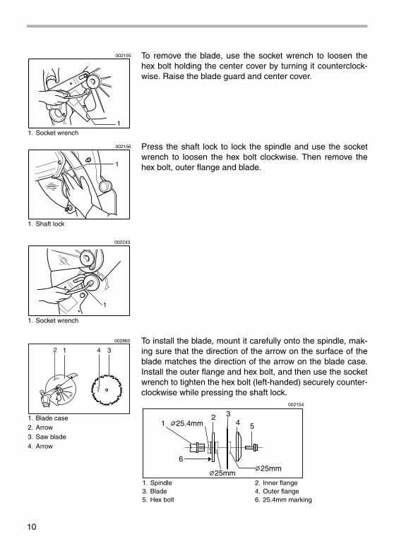
To remove the blade, use the socket wrench to loosen thehex bolt holding the center cover by turning it counterclock-wise. Raise the blade guard and center cover.
Press the shaft lock to lock the spindle and use the socketwrench to loosen the hex bolt clockwise. Then remove thehex bolt, outer flange and blade.
To install the blade, mount it carefully onto the spindle, mak-ing sure that the direction of the arrow on the surface of theblade matches the direction of the arrow on the blade case.Install the outer flange and hex bolt, and then use the socketwrench to tighten the hex bolt (left-handed) securely counter-clockwise while pressing the shaft lock.
1. Socket wrench1
002155
1. Shaft lock
1. Socket wrench
1
002156
1
002243
1. Blade case2. Arrow3. Saw blade4. Arrow
1 4 32
002860
1. Spindle 2. Inner flange3. Blade 4. Outer flange5. Hex bolt 6. 25.4mm marking
1
6
25mm
25.4mm
25mm
2 34 5
002154

11
CAUTION:• The inner flange has a 25 mm (63/64”) diameter on one
side and a 25.4 mm (1”) diameter on the other. The sidewith 25.4 mm (1”) diameter is marked by “25.4”. Use thecorrect side for the hole diameter of the blade you intendto use. Mounting the blade on the wrong side can resultin dangerous vibration.
Slip the pin on the blade guard into the slot in the guide armwhile returning the blade guard to its original fully closedposition. Then tighten the hex bolt clockwise to secure thecenter cover. Lower the handle to make sure that the bladeguard moves properly. Make sure shaft lock has releasedspindle before making cut.
Dust bagThe use of the dust bag makes cutting operations clean anddust collection easy. To attach the dust bag, fit it onto thedust nozzle.
When the dust bag is about half full, remove the dust bagfrom the tool and pull the fastener out. Empty the dust bag ofits contents, tapping it lightly so as to remove particles adher-ing to the insides which might hamper further collection.
NOTE:If you connect a Makita vacuum cleaner to your saw, moreefficient and cleaner operations can be performed.
Securing workpiece
WARNING:• It is extremely important to always secure the workpiece
properly and tightly with the vise. Failure to do so cancause the tool to be damaged and/or the workpiece tobe destroyed. PERSONAL INJURY MAY ALSO RESULT.Also, after a cutting operation, DO NOT raise the bladeuntil the blade has come to a complete stop.
1. Pin
1
002264
1. Dust nozzle2. Dust bug3. Fastener
1
2
3
002157
12
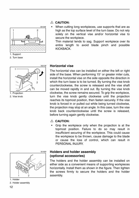
CAUTION:• When cutting long workpieces, use supports that are as
high as the top surface level of the turn base. Do not relysolely on the vertical vise and/or horizontal vise tosecure the workpiece.Thin material tends to sag. Support workpiece over itsentire length to avoid blade pinch and possibleKICKBACK.
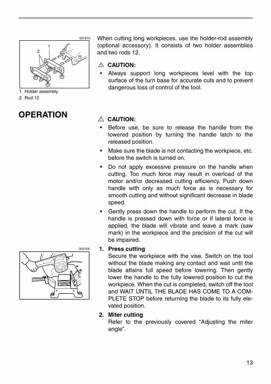
Horizontal viseThe horizontal vise can be installed on either the left or rightside of the base. When performing 15° or greater miter cuts,install the horizontal vise on the side opposite the direction inwhich the turn base is to be turned. By turning the vise knobcounterclockwise, the screw is released and the vise shaftcan be moved rapidly in and out. By turning the vise knobclockwise, the screw remains secured. To grip the workpiece,turn the vise knob gently clockwise until the projectionreaches its topmost position, then fasten securely. If the viseknob is forced in or pulled out while being turned clockwise,the projection may stop at an angle. In this case, turn the viseknob back counterclockwise until the screw is released,before turning again gently clockwise.
CAUTION:• Grip the workpiece only when the projection is at the
topmost position. Failure to do so may result ininsufficient securing of the workpiece. This could causethe workpiece to be thrown, cause damage to the bladeor cause the loss of control, which can result inPERSONAL INJURY.
Holders and holder assembly (optional accessories)The holders and the holder assembly can be installed oneither side as a convenient means of supporting workpieceshorizontally. Install them as shown in the figure. Then tightenthe screws firmly to secure the holders and the holderassembly.
1. Support2. Turn base
1 2
001549
1. Projection2. Vise knob
1
2
002158
1. Holder2. Holder assembly
1 2
001809
13
When cutting long workpieces, use the holder-rod assembly(optional accessory). It consists of two holder assembliesand two rods 12.
CAUTION:• Always support long workpieces level with the top
surface of the turn base for accurate cuts and to preventdangerous loss of control of the tool.
OPERATIONCAUTION:
• Before use, be sure to release the handle from thelowered position by turning the handle latch to thereleased position.
• Make sure the blade is not contacting the workpiece, etc.before the switch is turned on.
• Do not apply excessive pressure on the handle whencutting. Too much force may result in overload of themotor and/or decreased cutting efficiency. Push downhandle with only as much force as is necessary forsmooth cutting and without significant decrease in bladespeed.
• Gently press down the handle to perform the cut. If thehandle is pressed down with force or if lateral force isapplied, the blade will vibrate and leave a mark (sawmark) in the workpiece and the precision of the cut willbe impaired.
1. Press cuttingSecure the workpiece with the vise. Switch on the toolwithout the blade making any contact and wait until theblade attains full speed before lowering. Then gentlylower the handle to the fully lowered position to cut theworkpiece. When the cut is completed, switch off the tooland WAIT UNTIL THE BLADE HAS COME TO A COM-PLETE STOP before returning the blade to its fully ele-vated position.
2. Miter cuttingRefer to the previously covered “Adjusting the miterangle”.
1. Holder assembly2. Rod 12
12
001810
002159

14
3. Cutting aluminum extrusionWhen securing aluminum extrusions, use spacer blocksor pieces of scrap as shown in the figure to preventdeformation of the aluminum. Use a cutting lubricantwhen cutting the aluminum extrusion to prevent build-upof the aluminum material on the blade.
CAUTION:• Never attempt to cut thick or round aluminum extrusions.
Thick aluminum extrusions may come loose duringoperation and round aluminum extrusions cannot besecured firmly with this tool.
4. Wood facingUse of wood facing helps to assure splinter-free cuts inworkpieces. Attach a wood facing to the guide fenceusing the holes in the guide fence.See the figure concerning the dimensions for a sug-gested wood facing.
CAUTION:• Use straight wood of even thickness as the wood facing.
• Use screws to attach the wood facing to the guide fence.The screws should be installed so that the screw headsare below the surface of the wood facing.
• When the wood facing is attached, do not turn the turnbase with the handle lowered. The blade and/or thewood facing will be damaged.
NOTE:
• When the wood facing is attached, the maximum cuttingcapacities in width will be reduced by thickness of thewood facing.
1. Horizontal vise2. Spacer block3. Aluminum extrusion4. Guide fence
34
12
002861
1. Guide fence2. Wood facing
1
2
002160
1. Hole
10mm(3/8")
64mm(2-1/2") 154mm(6") 64mm(2-1/2")154mm(6")
45mm(1-3/4")
90mm(3-1/2")
11
Over 480mm(18-1/32")
002244

15
5. Cutting repetitive lengthsWhen cutting several pieces of stock to the same length,ranging from 300 mm (11 - 3/4”) to 400 mm (15 - 3/4”),use of the set plate (optional accessory) will facilitatemore efficient operation. Install the set plate on theholder (optional accessory) as shown in the figure.Align the cutting line on your workpiece with either theleft or right side of the groove in the kerf board, and whileholding the workpiece from moving, move the set plateflush against the end of the workpiece. Then secure theset plate with the screw. When the set plate is not used,loosen the screw and turn the set plate out of the way.
NOTE:
• Use of the holder-rod assembly (optional accessory)allows cutting repetitive lengths up to 2,200 mm (7.2 ft.)approximately.
Carrying toolMake sure that the tool is unplugged. Secure the turn base atright miter angle fully by means of the grip. Lower the handlefully and lock it in the lowered position by turning the handlelatch to the locked position.
Carry the tool by holding both sides of the tool base asshown in the figure. If you remove the holders, dust bag, etc.,you can carry the tool more easily.
CAUTION:• Always secure all moving portions before carrying the
tool.
• Handle latch is for carrying and storage purposes onlyand not for any cutting operations.
MAINTENANCECAUTION:
• Always be sure that the tool is switched off andunplugged before attempting to perform inspection ormaintenance.
1. Set plate2. Holder3. Screw
1
23
001846
1. Handle latch
1
002147
002263
16
WARNING:• Always be sure that the blade is sharp and clean for the
best and safest performance.
Adjusting the cutting angleThis tool is carefully adjusted and aligned at the factory, butrough handling may have affected the alignment. If your toolis not aligned properly, perform the following:
Loosen the grip which secures the turn base. Turn theturn base so that the pointer points to 0° on the miterscale. Then turn the turn base slightly clockwise andcounterclockwise to seat the turn base in the 0° miternotch. (Leave as it is if the pointer does not point to 0°.)Loosen the hex bolts securing the guide fence using thesocket wrench.
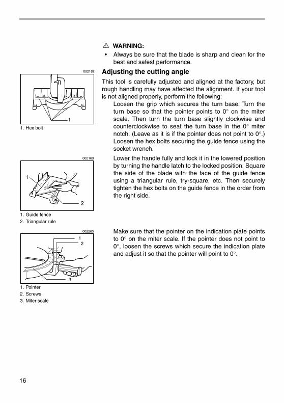
Lower the handle fully and lock it in the lowered positionby turning the handle latch to the locked position. Squarethe side of the blade with the face of the guide fenceusing a triangular rule, try-square, etc. Then securelytighten the hex bolts on the guide fence in the order fromthe right side.
Make sure that the pointer on the indication plate pointsto 0° on the miter scale. If the pointer does not point to0°, loosen the screws which secure the indication plateand adjust it so that the pointer will point to 0°.
1. Hex bolt
1
002162
1. Guide fence2. Triangular rule
1
2
002163
1. Pointer2. Screws3. Miter scale
12
3
002265

17
Adjusting for smooth handle actionThe hex lock nut which holds the gear housing and the armhas been factory adjusted to assure smooth handle action upand down and to guarantee precise cutting. Do not tamperwith it. Should looseness develop at the gear housing andarm connection, perform the following adjustment. Work thehandle up and down while tightening the hex lock nut; thebest position to tighten the hex lock nut is just before themotor body weight is obvious.After adjusting the hex lock nut, be sure that the handlereturns automatically to the initial, raised position from anyposition. If the hex lock nut is too loose, the cutting accuracywill be affected; if it is too tight, it will be hard to work the han-dle up and down. Note that this is a self locking nut. It is aspecial type that does not loosen in normal use. It should notbe overtightened or replaced with other types of nuts.
Replacing carbon brushesRemove and check the carbon brushes regularly. Replacewhen they wear down to the limit mark. Keep the carbonbrushes clean and free to slip in the holders. Both carbonbrushes should be replaced at the same time. Use only iden-tical carbon brushes.
Use a screwdriver to remove the brush holder caps. Take outthe worn carbon brushes, insert the new ones and securethe brush holder caps.
After replacing brushes, plug in the tool and break in brushesby running tool with no load for about 10 minutes. Thencheck the tool while running and electric brake operationwhen releasing the switch trigger. If electric brake is notworking well, ask your local Makita service center for repair.
After use• After use, wipe off chips and dust adhering to the tool
with a cloth or the like. Keep the blade guard cleanaccording to the directions in the previously coveredsection titled “Blade guard”. Lubricate the slidingportions with machine oil to prevent rust.
1. Gear housing2. Hex lock nut3. Arm
1
2
3
002161
1. Limit mark
1
001145
1. Screwdriver2. Brush holder cap
12
002164
18
To maintain product SAFETY and RELIABILITY, repairs, anyother maintenance or adjustment should be performed byMakita Authorized or Factory Service Centers, always usingMakita replacement parts.
ACCESSORIESCAUTION:
• These accessories or attachments are recommended foruse with your Makita tool specified in this manual. Theuse of any other accessories or attachments mightpresent a risk of injury to persons. Only use accessoryor attachment for its stated purpose.
If you need any assistance for more details regarding theseaccessories, ask your local Makita service center.
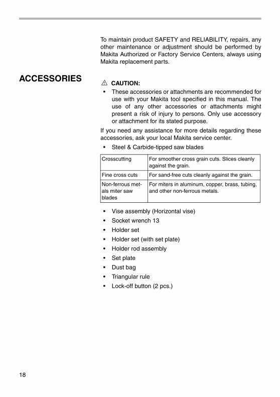
• Steel & Carbide-tipped saw blades
• Vise assembly (Horizontal vise)
• Socket wrench 13
• Holder set
• Holder set (with set plate)
• Holder rod assembly
• Set plate
• Dust bag
• Triangular rule
• Lock-off button (2 pcs.)
Crosscutting For smoother cross grain cuts. Slices cleanly against the grain.
Fine cross cuts For sand-free cuts cleanly against the grain.
Non-ferrous met-als miter saw blades
For miters in aluminum, copper, brass, tubing, and other non-ferrous metals.

Memo
19

Memo
20

21
First-ClassPostageRequired
Post Office willnot deliver
without properpostage.
Makita U.S.A., Inc.14930 Northam StreetLa Mirada, CA 90638-5753
Fold
Cut

22
1. This product was purchased from:
Home Center
Hardware/Lumber Store
Tool Distributor
Industrial Supply
Construction Supply
Other ( )
3. How did you learn about this product:
Magazine
From Dealer
Newspaper
Store Display
Catalog
Radio
Exhibition
From Friend
Previous Usage
Other ( )
2. Use of the product is intended for:
Construction Trade
Industrial Maintenance
Home Maintenance
Hobby
Other ( )
4. Most favored points are:
Repair Service
Durability
Power
Other ( )
Design
Features
Size
Price
Makita Brand
5. Any comments:
MAIL THIS PORTIONYour answers to the following questions are appreciated.
BE SURE TO COMPLETE THE CUSTOMER’S PORTION OF THIS FORM AND RETAIN FOR YOUR RECORDS.
DATE PURCHASED MODEL NO.
SERIAL NO.
INTL. LAST NAME / COMPANY NAME
STREET ADRESS
CITY
STATE
AGE:
ZIP CODE PHONE
AREACODE
STATUSMarried
SEXM FSingle
MONTH DAY YEAR
Under 19 20-29 30-39 40-49 50-60 Over 60
Please return this portion by facsimile or mail.Facsimile No: (714) 522-8133
Paste Paste Paste Paste Paste Paste Paste Paste
Pas
teP
aste
Pas
teP
aste
Pas
teP
aste
Pas
teP
aste
Pas
teP
aste
Pas
teP
aste

23
FACTORY SERVICE CENTERS1-800-4-MAKITA
RETAIN THIS PORTION FOR YOUR RECORDS
ALABAMA2365 Pelham ParkwayPelham, AL 35124 (205) 620-1791
ARIZONA3707 E. Broadway Rd., Ste. 6 Phoenix, AZ 85040 (602) 437-2850
ARKANSASShackleford Shopping Center 240 South Shackleford Rd., Ste. C Little Rock, AR 72211 (501) 224-5733
CALIFORNIA41850 Christy St. Fremont, CA 94538-5107 (510) 657-9881
1421 N. Clovis Ave., Ste. 112 Fresno, CA 93727 (559) 252-5166
14930 Northam St. La Mirada, CA 90638-5753 (714) 522-8088
1970 Fulton Avenue Sacramento, CA 95825 (916) 482-5197
1440 South “E” Street San Bernardino, CA 92408 (909) 885-1289
7674 Clairemont Mesa Blvd. San Diego, CA 92111 (858) 278-4471
1714 E.McFadden Ave., Unit M Santa Ana, CA 92705 (714) 667-5066
1565 Winchester B. Campbell, CA 95008-0501 (408) 379-0377
16735 Saticoy St., Ste. 105 Van Nuys, CA 91406 (818) 782-2440
COLORADO11839 E. 51st Ave. Denver, CO 80239-2709(303) 371-2850
CONNECTICUT508 Spring St. Windsor Locks, CT 06096(860) 292-6405
FLORIDA620 Douglas Ave. Suite 1302 Altamonte Springs, FL 32714 (407) 774-6000
750 East Sample RoadPompano Beach, FL 33064(954) 781-6333
Thompson Center Waters 5501 W. Waters Ave., Ste. 406 Tampa, FL 33634 (813) 886-8292
GEORGIA4680 River Green Parkway Duluth, GA 30096-2566 (770) 476-8911
HAWAII4510 Salt Lake Blvd., Suite A7 Honolulu, HI 96818(808) 847-0038
ILLINOIS1450 Feehanville Dr.Mt. Prospect, IL 60056-6011(847) 297-3100
INDIANA8403 Michigan Road, Unit 1Indianapolis, IN 46268(317) 334-9980
KANSAS8819 W. 95th St.Overland Park, KS 66212(913) 642-1111
KENTUCKY1215 S. Hurstbourne ParkwayLouisville, KY 40222(502) 326-3740
LOUSIANA5626 Jefferson Hwy.Harahan, LA 70123(504) 733-4138
MARYLAND7541 - 45 Ritchie HighwayGlen Burnie, MD 21061(410) 590-0160
MASSACHUSETTS232 Providence Hwy.Westwood, MA 02090(617) 461-9754
MICHIGAN37454 Ann Arbor TrailLivonia, MI 48150(313) 432-1012
MINNESOTA6427 Penn Ave. South Richfield, MN 55423 (612) 869-5199
MISSOURI9876 Watson Road St. Louis, MO 63126-2221 (314) 909-9889
NEBRASKA4129 S. 84th St. Omaha, NE 68127 (402) 597-2925
NEVADA3375 S. Decatur Blvd. Suites. 22 - 24 Las Vegas, NV 89102 (702) 368-4277
NEW JERSEY251 Herrod Blvd. Dayton, NJ 08810-1539 (609) 655-1212
NEW MEXICO5805 Menaul Blvd. NE Albuquerque, NM 87110 (505) 881-4619
NEW YORK4917 Genessee Street Cheektowaga, NY 14225 (716) 685-9503
131-35 31st Ave. Flushing, NY 11354 (718) 886-0971
NORTH CAROLINA3501-G S. Tryon St. Charlotte, NC 28217 (704) 527-0611
OHIO6253 E. Main St. Columbus, OH 43213 (614) 860-0222
6379 Pearl Road Parma Heights, OH 44130 (440) 843-7555
1617 E. Kemper Rd. Sharonville, OH 45246 (513) 771-0788
OKLAHOMA552 E. Memorial Road Oklahoma City, OK 73114 (405) 752-2655
OREGON828 19th Avenue., N.W. Portland, OR 97209 (503) 222-1823
PENNSYLVANIASpringwater Plaza364 Wilmington W. Chester Pike Glen Mills, PA 19342(610) 459-4122
6200 Babcock Blvd Pittsburgh, PA 15237 (412) 366-6363
PUERTO RICO200 Guayama St. Hato Rey, PR 00917 (787) 250-8776
TENNESSEE 4655 Nolensville Rd. Nashville, TN 37211 (615) 331-9922
TEXAS12801 Stemmons Fwy Ste. 809 Farmers Branch, TX 75234(972) 243-1150
12701 Directors Dr. Stafford, TX 77477-3701 (281) 565-8665
3453 IH-35 North, Ste. 101San Antonio, TX 78219(210) 228-0676
UTAH145 E. 1300 S., Ste. 101 Salt Lake City, UT 84115 (801) 359-3410
VIRGINIA5760 Northampton Blvd,. Ste. 102Virginia Beach, VA 23455(757) 460-0280
WASHINGTON22220 84th Ave. So., Bldg. A Kent, WA 98032(253) 395-8055
WISCONSINLincoln Plaza Shopping Ctr. 2245 S. 108th St. West Allis, WI 53227 (414) 541-4776
CUSTOMER’S RECORD
When you need service: Sendcomplete tool (prepaid) to oneof the Makita Factory ServiceCenters listed, or to an AuthorizedMakita Service Center. Be sureto attach a letter to the outside ofthe carton detailing the problemwith your tool.
Date Purchased
Dealer’s Name & Address
Model No.
Serial No.

WARNINGSome dust created by power sanding, sawing, grinding, drilling, and otherconstruction activities contains chemicals known to the State of Californiato cause cancer, birth defects or other reproductive harm. Some examplesof these chemicals are:• lead from lead-based paints, • crystalline silica from bricks and cement and other masonry products, and• arsenic and chromium from chemically-treated lumber.
Your risk from these exposures varies, depending on how often you do thistype of work. To reduce your exposure to these chemicals: work in a wellventilated area, and work with approved safety equipment, such as thosedust masks that are specially designed to filter out microscopic particles.
MAKITA LIMITED ONE YEAR WARRANTYWarranty Policy
Every Makita tool is thoroughly inspected and tested before leaving the factory. It is warranted to be free of defects from workmanship and materials for the period of ONE YEAR from the date of original purchase. Should any trouble develop during this one-year period, return the COMPLETE tool, freight prepaid, to one of Makita's Factory or Authorized Service Centers. If inspection shows the trouble is caused by defective workmanship or material, Makita will repair (or at our option, replace) without charge.
This Warranty does not apply where:
• repairs have been made or attempted by others:
• repairs are required because of normal wear and tear:
• the tool has been abused, misused or improperly maintained:
• alterations have been made to the tool.
IN NO EVENT SHALL MAKITA BE LIABLE FOR ANY INDIRECT, INCIDENTAL OR CONSEQUENTIAL DAMAGES FROM THE SALE OR USE OF THE PRODUCT. THIS DISCLAIMER APPLIES BOTH DURING AND AFTER THE TERM OF THIS WARRANTY.
MAKITA DISCLAIMS LIABILITY FOR ANY IMPLIED WARRANTIES, INCLUDING IMPLIED WARRANTIES OF "MERCHANTABILITY" AND "FITNESS FOR A SPECIFIC PURPOSE," AFTER THE ONE-YEAR TERM OF THIS WARRANTY.
This Warranty gives you specific legal rights, and you may also have other rights which vary form state to state. Some states do not allow the exclusion or limitation of incidental or consequential damages, so the above limitation or exclusion may not apply to you. Some states do not allow limitation on how long an implied warranty lasts, so the above limitation may not apply to you.
Makita Corporation3-11-8, Sumiyoshi-cho,
Anjo, Aichi 446-8502 Japan
883619E060