installation and operation manual - babco lathes/rl-4500/rl-4500... · brake drums / first scratch...
TRANSCRIPT
Forward this manual to all operators.Failure to operate this equipment asdirected may cause injury or death.
MODEL RL4500COMBINATION BRAKE LATHE
FOR RESURFACING AUTOMOBILE AND LIGHT TRUCKDRUMS, ROTORS AND FLYWHEELS
INSTALLATION AND OPERATION MANUAL
SHIPPING DAMAGE CLAIMSWhen this equipment is shipped, title passes to thepurchaser upon receipt from the carrier.Consequently, claims for the material damaged inshipment must be made by the purchaser against thetransportation company at the time shipment isreceived.
BE SAFEYour new Ranger brake lathe was designed andbuilt with safety in mind. However, your overallsafety can be increased by proper training andthoughtful operation on the part of the operator.DO NOT operate or repair this equipmentwithout reading this manual and the importantsafety instructions shown inside.
1645 Lemonwood Dr.Santa Paula, CA. 93060, USA
Tel: 1-805-933-9970Fax: 1-805-933-9160
Keep this operation manual near themachine at all times. Make sure that
ALL USERS read this manual .
TABLE OF CONTENTS
Contents Page No.
Owner’s Responsibility . . . . . . . . . . . . . . . . . . . . . . . .3
Definitions of Hazard Levels . . . . . . . . . . . . . . . . . . . . 3
Warning Instructions . . . . . . . . . . . . . . . . . . . . . . . . . . 4
Before You Begin . . . . . . . . . . . . . . . . . . . . . . . . . . . . .4
Electrical Requirements . . . . . . . . . . . . . . . . . . . . . . . .4
Important Safety Instructions . . . . . . . . . . . . . . . . . . . . 5
Features . . . . . . . . . . . . . . . . . . . . . . . . . . . . . . . . . . . 6
Specifications . . . . . . . . . . . . . . . . . . . . . . . . . . . . . . .6
Assembly View . . . . . . . . . . . . . . . . . . . . . . . . . . . . . .7
Installation . . . . . . . . . . . . . . . . . . . . . . . . . . . . . .8
Brake Rotor/Drum Inspection. . . . . . . . . . . . . . . . . . .8
Basic Operation. . . . . . . . . . . . . . . . . . . . . . . . . . .8
Reconditioning Brake Drums / Start. . . . . . . . . . . . . . . .9
Mounting Hubbed Brake Drums. . . . . . . . . . . . . . . .10
Mounting Hubless Brake Drums. . . . . . . . . . . . . . . . . . .10
Reconditioning Brake Drums Continued . . . . . . . . . .11
Brake Drums / First Scratch Cut . . . . . . . . . . . . . . . .11
Brake Drums / Determine Depth of Cut . . . . . . . . . . . .12
Reconditioning Brake Rotors / Start. . . . . . . . . . . . .13
Mounting Hubbed Brake Rotors . . . . . . . . . . . . . . . . . .13
Mounting Hubless Brake Rotors. . . . . . . . . . . . . . . . .14
Reconditioning Brake Rotors / Continued . . . . . . .14 - 16
Reconditioning Flywheels . . . . . . . . . . . . . . . . . .17
Adjusting Spindle Speed . . . . . . . . . . . . . . . . . . . .17
Installation Floor Space . . . . . . . . . . . . . . . . . . . .18
Maintenance . . . . . . . . . . . . . . . . . . . . . . . . . . .18
Parts Listing / Cross Feed Group . . . . . . . . . . . . . . .19
Parts Listing / Spindle Group Assembly. . . . . . . . . . .20
Parts Listing / Micro-Dial Group . . . . . . . . . . . . . . . . . 21
Parts Listing / Variable Speed Gearbox. . . . . . . . . . .22
Parts Listing / Cross Feed Assembly. . . . . . . . . . . . .23
Parts Listing / Motor - Drive Group. . . . . . . . . . .22
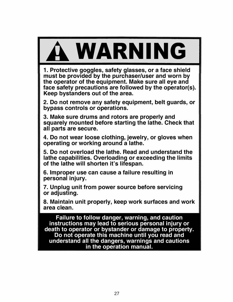
Failure to follow danger, warning, and cautioninstructions may lead to serious personal injury or death
to operator or bystander or damage to property.
Do not operate this machine until you read andunderstand all the dangers, warnings and cautions
in this manual.
For additional copiesor further information, contact:
Bend-Pak Inc. / Ranger Products1645 Lemonwood Dr.,
Santa Paula, CA. 93060 1-805-933-9970
www.bendpak.com
OPERATOR PROTECTIVEEQUIPMENT
Personal protective equipment helps make brake servicesafer. However, equipment does not take the place of safeoperating practices. Always wear durable work clothingduring service activity. Shop aprons or shop coats mayalso be worn, however loose fitting clothing should beavoided. Tight fitting leather gloves are recommended toprotect operators hands when handling brake parts.Sturdy leather work shoes with steel toes and oil resistantsoles should be used by all service personnel to helpprevent injury in typical shop activities. Eye protection isessential during rotor resurfacing. Safety glasses with sideshields, goggles, or face shields are acceptable. Backbelts provide support during lifting activities and are alsohelpful in providing operator protection. Considerationshould also be given to the use of hearing protection ifbrake service activity is performed in an enclosed area, orif noise levels are high.
THIS SYMBOL POINTS OUT IMPORTANT SAFETY INSTRUCTIONS WHICH IF NOT FOLLOWEDCOULD ENDANGER THE PERSONAL SAFETY AND/OR PROPERTY OF YOURSELF AND OTHERSAND CAN CAUSE PERSONAL INJURY OR DEATH. READ AND FOLLOW ALL INSTRUCTIONS IN
THIS MANUAL BEFORE ATTEMPTING TO OPERATE THIS MACHINE.
2

DEFINITIONS OF HAZARD LEVELS
Identify the hazard levels used in this manual with thefollowing definitions and signal words:
DANGERWatch for this symbol: It Means: Immediate hazardswhich will result in severe personal injury or death.
WARNINGWatch for this symbol: It Means: Hazards or unsafepractices which could result in severe personal injury ordeath.
CAUTIONWatch for this symbol: It Means: Hazards or unsafepractices which may result in minor personal injury orproduct or property damage.
Watch for this symbol! It means BE ALERT! Your safety, or the safety of others, is involved!
OWNER’S RESPONSIBILITY
To maintain machine and user safety, the responsibility ofthe owner is to read and follow these instructions:
Follow all installation instructions.
Make sure installation conforms to all applicable Local,State, and Federal Codes, Rules, and Regulations; suchas State and Federal OSHA Regulations and ElectricalCodes.
Carefully check the unit for correct initial function.
Read and follow the safety instructions. Keep themreadily available for machine operators.
Make certain all operators are properly trained, knowhow to safely and correctly operate the unit, and areproperly supervised.
Allow unit operation only with all parts in place andoperating safely.
Carefully inspect the unit on a regular basis andperform all maintenance as required.
Service and maintain the unit only with authorized orapproved replacement parts.
Keep all instructions permanently with the unit and alldecals on the unit clean and visible.
3

WARNING INSTRUCTIONS
1. This equipment incorporates parts such as electricalswitches which tend to produce sparks. When located in aservice facility, the unit should be in a ventilated room orenclosure provided for the purpose, or should be at least 18inches or more above floor to minimize the risk of ignitingfuel vapors.
2. Eye and face protection is required and stronglyrecommended: “Protective eye and face equipment isrequired to be used where there is a reasonable probabilityof injury that can be prevented by use of such equipment.”OSHA 1910.133 (a) Protective goggles, safety glasses, or aface shield must be provided by the purchaser/user andworn by the operator of the equipment. Make sure all eyeand face safety precautions are followed by the operator(s).Keep bystanders out of the area.
3. Do not remove any safety equipment such as guards,control switches or shut-off devices.
4. Make sure rotors are properly mounted and squarebefore starting the lathe. Check to make sure all parts aresecure.
5. Make sure the rotors are clean and mounted properlybefore attaching lathe to the caliper.
6. Do not overload the lathe. Read and understand the lathecapabilities prior to operation. Overloading the lathe canshorten the lifespan of the unit, and could cause a failureresulting in personal injury.
7. Check damaged parts carefully. Before further use of thelathe, a guard or other part that is damaged should becarefully checked. Immediately replace all damaged,missing, or non-functional parts. Check for alignment ofmoving parts, binding of moving parts, breakage of parts,mounting, and any other conditions that may affectoperation. Guards and other parts that are damaged shouldbe properly repaired or replaced before lathe is used again.
8. Always feed the blade or cutter into the work and againstthe direction of rotation. Cutters and tool bits are designedto begin the cut from near the center of the rotor to the outeredge. Do not attempt to cut from the outside edge into thecenter.
9. Never leave the brake lathe running unattended. Turn thepower off. Don’t leave the brake lathe until the power switchis turned to the OFF position.
10. Never use compressed air to blow and clear chips.Chips and dust may be driven between machined parts andinto bearings, causing undue wear. They may also contactpersons in the area causing personal injury.
BEFORE YOU BEGINReceiving:The shipment should be thoroughly inspected as soon as itis received. The signed bill of lading is acknowledgement bythe carrier of receipt in good condition of shipment coveredby your invoice. If any of the goods called for on this bill oflading are shorted or damaged, do not accept them until thecarrier makes a notation on the freight bill of the shorted ordamaged goods. Do this for your own protection.
NOTIFY THE CARRIER AT ONCE if any hidden loss ordamage is discovered after receipt and request the carrierto make an inspection. If the carrier will not do so, preparea signed statement to the effect that you have notified thecarrier (on a specific date) and that the carrier has failed tocomply with your request.
IT IS DIFFICULT TO COLLECT FOR LOSS OR DAM-AGEAFTER YOU HAVE GIVEN THE CARRIER A CLEARRECEIPT. File your claim with the carrier promptly. Supportyour claim with copies of the bill of lading, freight bill,invoice, and photographs, if available. Our willingness toassist in helping you process your claim does not makeRanger Products responsible for collection of claims orreplacement of lost or damaged materials.
ELECTRICAL REQUIREMENTSThis unit requires power from a 15 amp 110 volt electricalcircuit. The lathe must be properly grounded to protect theoperator from shock. The RL4500 is equipped with anapproved power cord and 3-prong grounding-type plug.Should an extension cord be required, be sure to use asimilar size power cord with 3-prong grounding plug and a3-prong grounding receptacle properly rated to handle theelectrical requirement of this unit. Do not modify a cord orplug to match a receptacle; have a qualified electricianinstall an appropriate outlet to match the latherequirements. Repair or replace any worn or damagedpower cords immediately.
IMPORTANT NOTEFor 220 volt operation it will be necessary to replace the
110 volt 3-prong plug with an appropriate 220 volt 3-prongplug with ground. After changing the plug, position thevoltage selector switch at the rear of the unit to the 220setting. Verify that the lathe plug and grounding-type
receptacle match.
4
IMPORTANT NOTICEDo not attempt to operate this equipment if you have never been trained on basic brake lathe operation procedures.Stay clear of moving parts that can cause injury. These instructions must be followed to insure proper installation and
operation. Failure to comply with these instructions can result in serious bodily harm and void product warranty.Manufacturer will assume no liability for loss or damage of any kind, expressed or implied resulting from improper
installation, operation or use of this product. PLEASE READ ENTIRE MANUAL PRIOR TO INSTALLATION.
5
IMPORTANT SAFETY INSTRUCTIONSBefore operating the lathe, review the warning information on the lathe and the cautions, warnings and dangers
in this manual. Also review the following general safety instructions.
When using your brake lathe basic safety precautionsshould always be followed, including the following:
KEEP GUARDS IN PLACE and in working order.
KEEP HANDS clear of moving parts at all times. Keephair, loose clothing, neckties, shop rags, jewelry, fingers,and all parts of body away from moving parts.
ALWAYS USE SAFETY GLASSES. Everyday eyeglass-es only have impact resistant lenses, they are NOT safetyglasses. Safety glasses, goggles, or a face shield will help pro-tect the operator from injury. Use a face shield and dust maskduring all operations.
SECURE WORK properly for setup and tool bitpositioning before attempting to make first cut. Do notattempt to touch rotors or drums with your hands with thelathe in operation.
REMOVE ADJUSTING KEYS AND WRENCHESfrom the lathe before turning it on.
MAINTAIN TOOLS WITH CARE. Keep tools sharpand clean for best and safest performance. Followinstructions for lubricating and changing accessories.
USE FACTORY APPROVED TOOLS ONLY. Don’tforce a tool or an attachment to do a job for which it wasnot designed. The use of improper accessories maycause risk of injury to operator or bystanders. Use only asdescribed in this manual. Use only manufacturer’srecommended attachments.
KEEP WORK AREA CLEAN and well lighted.Cluttered areas and benches invite accidents.
LOCATE POWER CORD SAFELY. Do not let powercord come in contact with moving parts.
REDUCE RISK OF FIRE. Do not operate equipment innear open containers of flammable liquids and their vapors.
PROVIDE ADEQUATE VENTILATION when workingon operating internal combustion engines. Vehicleexhaust must be vented from work area.
DRESS PROPERLY. Keep hair, loose clothing,neckties, shop rags, jewelry, fingers, and all parts of bodyaway from moving parts. Non-slip footwear isrecommended.
ALWAYS UNPLUG EQUIPMENT from electricaloutlet when not in use. Never use the cord to pull the plugfrom the outlet. Grasp plug firmly and pull to disconnect.
DO NOT TOUCH HOT PARTS. Care must be takenas burns can occur from touching hot parts.
PROPERLY MAINTAIN EQUIPMENT. Do not operateequipment with a damaged cord or if the equipment hasbeen dropped or damaged—until it has been examinedby a qualified serviceman.
REDUCE RISK OF SHOCK. Do not use on wetsurfaces or expose to rain.
KEEP CHILDREN/UNAUTHORIZED PERSONSAWAY. All bystanders should be kept completely awayfrom the work area.
REMOVE POWER AND DISCONNECT TOOLSbefore servicing the unit and when changing accessoriessuch as blades, bits, cutters, etc. Follow lock-out andtag-out procedures as required.
AVOID UNINTENTIONAL STARTING. Make sure theswitch is in the OFF position before plugging the machinein or performing any maintenance or service work.
NEVER LEAN OR STAND ON THE LATHE. Seriousinjury could occur if the lathe is tipped over or if the cut-ting tool is unintentionally contacted.
6
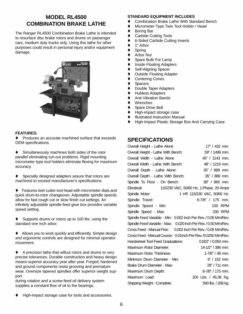
MODEL RL4500COMBINATION BRAKE LATHE
The Ranger RL4500 Combination Brake Lathe is intendedto resurface disc brake rotors and drums on passengercars, medium duty trucks only. Using this lathe for otherpurposes could result in personal injury and/or equipmentdamage.
FEATURES: Produces an accurate machined surface that exceeds
OEM specifications.
Simultaneously machines both sides of the rotorparallel eliminating run-out problems. Rigid mountingmicrometer type tool holders eliminate flexing for maximumaccuracy.
Specially designed adapters assure that rotors aremachined to exceed manufacturer's specifications.
Features twin cutter tool head with micrometer dials andquick drum-to-rotor changeover. Adjustable spindle speedsallow for fast rough cut or slow finish cut settings. Aninfinitely adjustable spindle-feed gear box provides variablespeed setting.
Supports drums or rotors up to 100 lbs. using thestandard one inch arbor.
Allows you to work quickly and efficiently. Simple designand ergonomic controls are designed for minimal operatormovement.
A precision lathe that willcut rotors and drums to veryprecise tolerances. Durable construction and heavy designmeans superior accuracy year after year. Forged, hardenedand ground components resist grooving and prematurewear. Oversize tapered spindles offer superior weight sup-portduring rotation and a screw-feed oil delivery systemsupplies a constant flow of oil to the bearings.
High-impact storage case for tools and accessories.
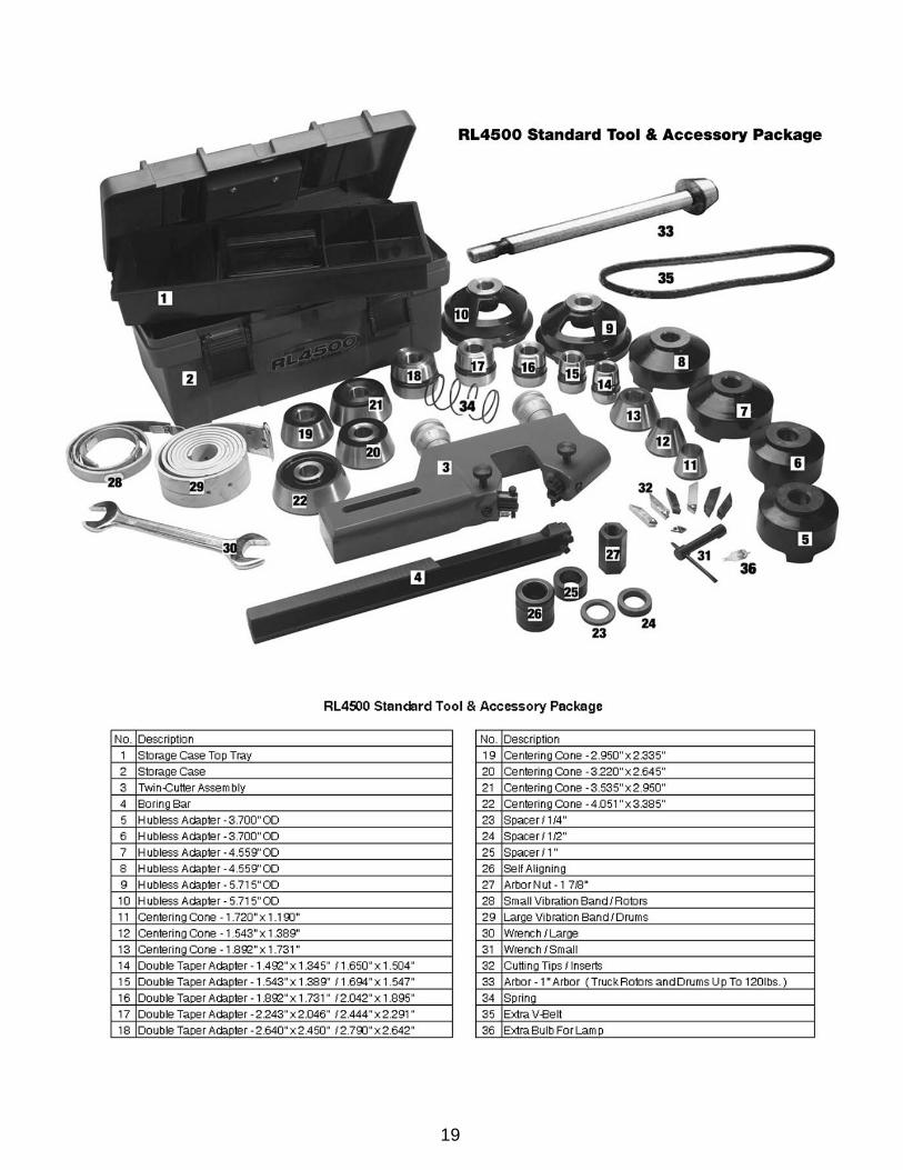
STANDARD EQUIPMENT INCLUDES Combination Brake Lathe With Standard Bench Micrometer-Type Twin Tool Holder / Head Boring Bar Carbide Cutting Tools 6-Sided Carbide Cutting Inserts 1" Arbor Spring Arbor Nut Spare Bulb For Lamp Inside Floating Adapters Self-Aligning Spacer Outside Floating Adapter Centering Cones Spacers Double Taper Adapters Hubless Adapters Anti-Vibration Bands Wrenches Spare Drive Belt High-impact storage case Illustrated Instruction Manual High-Impact Plastic Storage Box And Carrying Case
SPECIFICATIONSOverall Height - Lathe Alone 17” / 432 mm.Overall Height - Lathe With Bench: 59” / 1499 mm.Overall Width - Lathe Alone 45” / 1143 mm.Overall Width - Lathe With Bench: 48” / 1219 mm.Overall Depth - Lathe Alone: 35” / 889 mm.Overall Depth - Lathe With Bench: 35” / 889 mm.Spindle To Floor - On Bench: 38” / 965 mm.Electrical: 115/230 VAC, 50/60 Hz, 1-Phase, 20 AmpsSpindle Motor: 1 HP, 115/230 VAC, 50/60 Hz.Spindle Travel: 6-7/8” / 175 mm.Spindle Speed - Min: 100 RPMSpindle Speed - Max: 200 RPMSpindle Feed Variable: - Min: 0.002 Inch Per Rev. / 0.05 Mm/Rev.Spindle Feed Variable: - Max: 0.020 Inch Per Rev. / 0.50 Mm/Rev.Cross Feed - Manual Fine: 0.002 Inch Per Rev. / 0.05 Mm/Rev.Cross Feed - Manual Course: 0.01Inch Per Rev. /0.0250 Mm/Rev.Handwheel Tool Feed Graduations: 0.002” / 0.050 mm.Maximum Rotor Diameter: 14-1/2” / 386 mm.Maximum Rotor Thickness: 1-7/8” / 48 mm.Minimum Drum Diameter - Min: 6” / 152 mm.Brake Drum Diameter - Max: 28” / 711 mm.Maximum Drum Depth: 6-7/8” / 175 mm.Maximum Load: 100 Lbs. / 45.36 Kg.Shipping Weight - Complete: 590 lbs. / 268 kg.

7

INSTALLATION
1. Assemble the bench and chip trays according to thediagram on page 7. Tighten all fasteners securely.
2. After assembly, the bench should be leveled. The benchmay be bolted down with 3/8” concrete bolts or lag screws.
3. Unbolt the lathe from the shipping pallet and removeany packing materials and protective wrapping. Lift thelathe onto the bench.
Always follow safe lifting practices when lifting heavy loads.Use a forklift or crane only. Do not attempt to lift lathe unit
onto the bench without the use of material handlingequipment with a lifting capacity 400 pounds or greater.
4. Bolt the lathe to the bench with the hardware provided.Tighten fasteners securely.
5. Remove any packing materials and protective wrappingfrom the lathe and components.
6. Make sure the lathe is turned off. Plug lathe into a properlyinstalled and grounded outlet that matches the lathe plug.
IMPORTANT NOTEPosition the voltage selector switch at the rear of the unit tothe appropriate voltage setting before plugging the lathe into
outlet. Verify that the lathe plug and grounding-typereceptacle match.
7. Remove the oil plug, insert the oil dipstick, and check oillevel. The lathe is shipped with the correct amount andtype of oil. Add oil as necessary to reach the correct markon the dipstick. Use only EP-80-90 gear oil. Oil levelshould be checked often.
BRAKE ROTOR/DRUM INSPECTION1. Before attempting any resurfacing, rotor and/or druminspection is necessary. Determine the manufacturer'sspecifications from an approved specification guide.
2. Using a digital micrometer or other measuring tool, recordthe thickness of the rotor or drum. Observe any deep scoresand gouges. This depth will also need to be recorded.
3. Determine if the total amount of material to be removedwill meet the manufacturer's minimum specifications. If anyrotor is found to be below minimum specifications as calledfor by the vehicle manufacturer, replace as required.
BASIC OPERATIONTo help you understand drum and rotor turning, read thefollowing that helps explain the features, operation andprinciples of drum and rotor resurfacing.
Horizontal Spindle / ArborThe spindle (horizontal main shaft) is motor driven andturns the arbor (main rod with threaded tip) which the brakedrums or rotors are mounted on. When turning the drum orrotor via the arbor and holding a cutting tool against thebraking surface, metal can be removed making the finalresult a smooth finish that meets original factoryspecifications. Smooth brake surfaces will extend the life ofthe brake pads and increase brake operation efficiency.
8
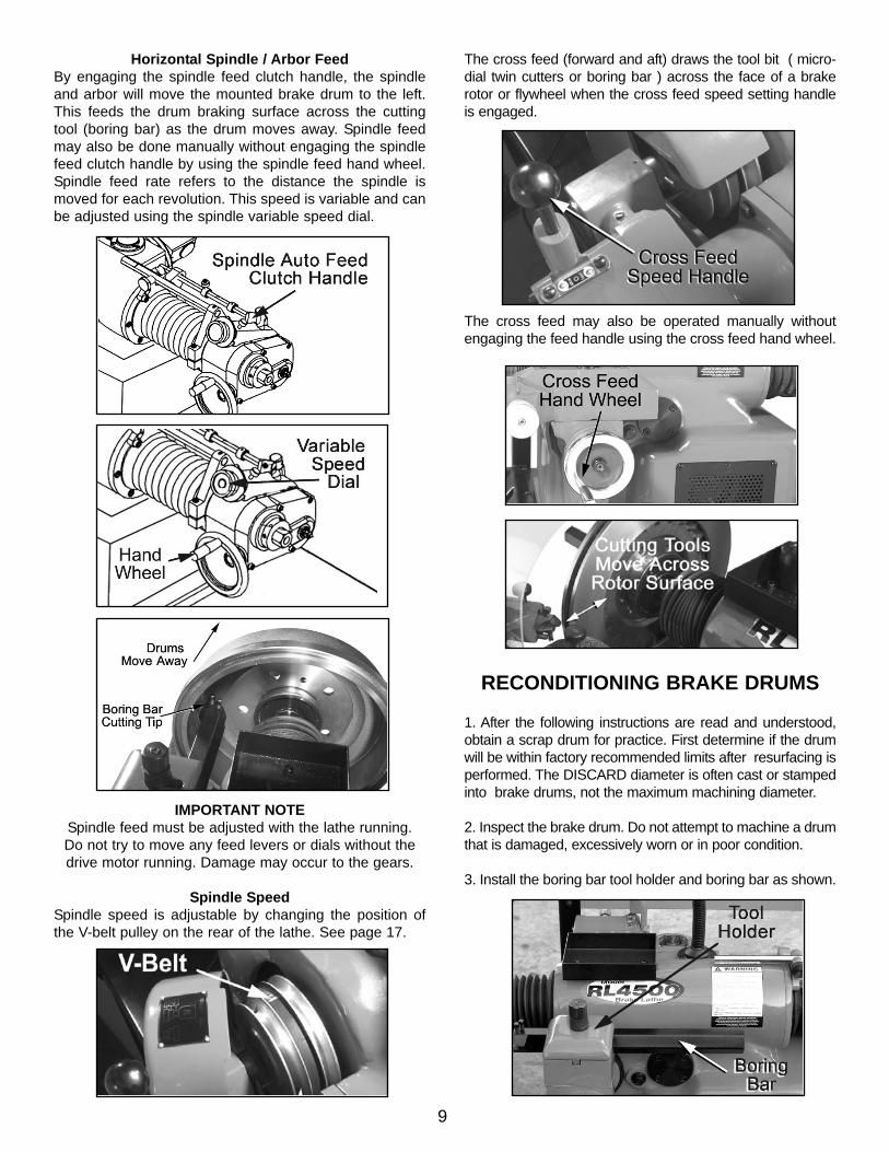
Horizontal Spindle / Arbor FeedBy engaging the spindle feed clutch handle, the spindleand arbor will move the mounted brake drum to the left.This feeds the drum braking surface across the cuttingtool (boring bar) as the drum moves away. Spindle feedmay also be done manually without engaging the spindlefeed clutch handle by using the spindle feed hand wheel.Spindle feed rate refers to the distance the spindle ismoved for each revolution. This speed is variable and canbe adjusted using the spindle variable speed dial.
IMPORTANT NOTESpindle feed must be adjusted with the lathe running. Do not try to move any feed levers or dials without thedrive motor running. Damage may occur to the gears.
Spindle SpeedSpindle speed is adjustable by changing the position ofthe V-belt pulley on the rear of the lathe. See page 17.
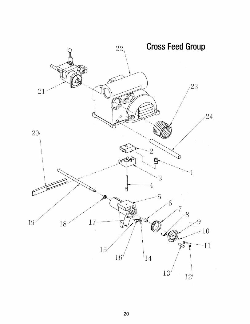
Cross Feed
The cross feed (forward and aft) draws the tool bit ( micro-dial twin cutters or boring bar ) across the face of a brakerotor or flywheel when the cross feed speed setting handleis engaged.
The cross feed may also be operated manually withoutengaging the feed handle using the cross feed hand wheel.
RECONDITIONING BRAKE DRUMS
1. After the following instructions are read and understood,obtain a scrap drum for practice. First determine if the drumwill be within factory recommended limits after resurfacing isperformed. The DISCARD diameter is often cast or stampedinto brake drums, not the maximum machining diameter.
2. Inspect the brake drum. Do not attempt to machine a drumthat is damaged, excessively worn or in poor condition.
3. Install the boring bar tool holder and boring bar as shown.
9

4. Be sure that a proper tool bit is secure in the boring barand the cutting tip is not excessively worn. Sharp cuttingtips must be used at all times. A dull cutter will affect thefinish of both drums and rotors. If the cutting edge isdamaged, replace it promptly. Be sure no metal chips areunder tip when changing tips.
5. Mount the drum on the arbor using the proper adapters,cones, and spacers.
Mounting Hubbed Brake DrumsTapered centering cones or double taper adapters fit in thebearing seats. Be sure to make contact as close as possible tothe middle of the bearing race as possible. Various adaptersand/or spacers may be used to fill out the shaft of the arbor.
Mounting Hubless Brake DrumsSelect the largest hubless adapter possible that will fit insidethe drum against the flat lug hole surface. Be sure tostraddle the bolt holes to avoid mounting against a burr, orremove the burrs with a grinding stone before mounting.Slip the hubless adapter onto the arbor followed by a spring,centering cone, the drum, and another similar size hublessadapter. The centering cone will fit into the center hole of thedrum from the inside to center the drum on the arbor. Fill outthe remaining shaft with various adapters and/or spacersas needed.
IMPORTANT NOTEThe arbor nut has REVERSE THREADS. Tighten by
turning the arbor nut COUNTER-CLOCKWISE.
IMPORTANT NOTEThe self-aligning spacer should always be used next tothe arbor nut when tightening. To avoid overtightening,
wrench turn the arbor nut counterclockwise until thedrum and adapters become fixed snug on the arbor andso that you are unable to freely turn them. Then continue
to advance the wrench 1/4 of a turn only. DO NOTovertighten the arbor nut.
Handle Adapters With CareThe adapters, arbor, and spindle are made
of top grade steel, hardened, and precision ground toclose tolerances. Great care should be taken in their use,
handling, and storage. The smallest nick or scratch cancause incorrect drum or rotor alignment resulting in
inaccurate resurfacing.
6. Wrap a drum silencing band snugly around the drum.Be sure it is positioned towards the right-hand edge ornearest the open side of the drum. IMPORTANT - Failureto use a silencing band will cause premature wear of toolcutters and result in a poor finish cut.
10

7. Using the cross feed hand wheel, move the cross feedto its innermost position by turning the hand wheelclockwise.
8. Using the spindle feed hand wheel, move the spindle toits innermost (right hand) position by turning the handwheel clockwise and then back off by turning dial wheelfive turns counterclockwise. NOTE: If the hand wheel doesnot turn freely, check to make sure the spindle lock andtravel control lock knobs are loosened.
9. Next, position the boring bar by loosening the tool holdernut and sliding the boring bar towards the innermost side ofthe drum, within 1/4” away from the braking surface.
IMPORTANT NOTEThe boring bar position will have to be changed
whenever a drum of different diameter is machined. Theentire boring bar tool holder may be swiveled to achieve
the best cutting position.
10. Check all clearances closely to make sure that nothingwill “crash” when the power is turned on and the drumstarts rotating. NOTE: It may help to turn the arbor nutcounter-clockwise and manually turn the drum by hand topre-check all clearances.
Before turning the power on, make sure the cross feedspeed setting handle and the spindle feed clutch handle
are in their neutral positions.
11. Turn the power on.
12. Turn the cross feed hand wheel counterclockwise andbring the boring bar cutting tip into the braking surfaceuntil it just barely contacts the drum surface and makes aslight scratch cut.
KEEP HANDS clear of moving parts at all times. Keephair, loose clothing, neckties, shop rags, jewelry, fingers,
and all parts of body away from moving parts.
Always wear safety glasses or a face shield. Cutting anexposed surface such as a brake drum or rotor will
produce flying chips and debris.
11
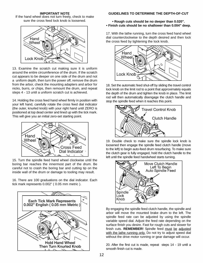
IMPORTANT NOTEIf the hand wheel does not turn freely, check to make
sure the cross feed lock knob is loosened.
13. Examine the scratch cut making sure it is uniformaround the entire circumference of the drum. If the scratchcut appears to be deeper on one side of the drum and nota uniform depth, then turn the power off, remove the drumfrom the arbor, check the mounting adapters and arbor fornicks, burrs, or chips, then remount the drum, and repeatsteps 4 - 13 until a uniform scratch cut is achieved.
14. Holding the cross feed hand wheel firmly in position withyour left hand, carefully rotate the cross feed dial indicator(the outer, knurled knob) with your right hand until ZERO ispositioned at top dead center and lined up with the tick mark.This will give you an initial zero-set starting point.
15. Turn the spindle feed hand wheel clockwise until theboring bar reaches the innermost part of the drum. Becareful not to crash the boring bar and cutting tip on theinside wall of the drum or damage to tooling may result.
16. There are 100 graduations on the dial indicator. Eachtick mark represents 0.002” ( 0.05 mm metric ).
GUIDELINES TO DETERMINE THE DEPTH-OF-CUT
• Rough cuts should be no deeper than 0.020”.• Finish cuts should be no shallower than 0.004” deep.
17. With the lathe running, turn the cross feed hand wheeldial counterclockwise to the depth desired and then lockthe cross feed by tightening the lock knob.
18. Set the automatic feed shut-off by sliding the travel controllock knob on the limit rod to a point that approximately equalsthe depth of the drum and tighten the knob in place. The limitrod will then automatically disengage the clutch handle andstop the spindle feed when it reaches this point.
19. Double check to make sure the spindle lock knob isloosened then engage the spindle feed clutch handle (moveto the left) to begin auto-feed drum resurfacing. To make surethe clutch gear is fully engaged, hold the clutch handle to theleft until the spindle feed handwheel starts turning.
By engaging the spindle feed clutch handle, the spindle andarbor will move the mounted brake drum to the left. Thespindle feed rate can be adjusted by using the spindlevariable speed dial. Adjust the feed rate depending on thesurface finish you desire. Fast for rough cuts and slower forfinish cuts. REMEMBER! Spindle feed must be adjustedwith the lathe running only. Do not try to adjust speed dialwithout the drive motor running or gear damage will occur.
20. After the first cut is made, repeat steps 14 - 19 until asmooth finish cut is made.
12

RECONDITIONING BRAKE ROTORS
After the following instructions are read and understood,obtain a scrap rotor for practice. Inspect all rotorscarefully for excessive scoring, rust ridges (at the innerand outer circumference of the rotor), and blemished hardspots. Any excessive wear or deformity should be noted. Ifthe rotor is not within acceptable limits, the rotor should bereplaced.
Always use a micrometer to check the thickness of therotor. If the rotor thickness is less than the minimumestablished by the manufacturer, or if it will be less afterreconditioning, the rotor should be replaced.
Twin CuttersA micro-dial twin cutter tool assembly is used to
recondition both surfaces of a brake rotor at the sametime. The twin cutter replaces the boring bar on top ofthe cross feed after removing the boring bar and tool
holder boring bar brackets.
Practice setting the micro-dial cutters for machining rotors.Learn all the functions thoroughly to insure properoperation. Most rotors will have the minimum thicknessvalues cast into the outer surface.
The proper procedure for determining whether toresurface rotors or discard them is as follows:
A. Using a micrometer or some other micrometer suitablefor measuring the thickness of the rotor to be machined,check the rotor thickness at four points (90 degrees apart)about 1" from the outer diameter.
B. If the thickness at any of the four points is less than theminimum established by car manufacturers as shown onthe rotor or in a current brake specifications book, replacethe rotor.
C. The rotor may be resurfaced if scored or it has a smallamount of runout, provided it is within the minimumthickness requirement.
D. After the rotor is machined, measure the thicknessagain, and, if it is not within the allowable minimum limits,discard it. NOTE: This check requires a measurement inonly one spot if both braking surfaces cleaned up 100%,because the turning operation assures almost absoluteparallelism.
Preparing For Twin Cutters1. Remove the boring bar and tool holder brackets.
2. Using the spindle feed hand wheel, move the spindle toits innermost (right hand) position by turning the handwheel clockwise and then back off by turning dial wheelthree turns counterclockwise. On some deeper rotors itmay be necessary to move the spindle farther left. Forbest results, always position the spindle as far to the rightas the job will allow. NOTE: If the hand wheel does notturn freely, check to make sure the spindle lock and trav-el control lock knobs are loosened.
3. Turn the cross feed hand wheel counterclockwise andmove the cross feed assembly away from the arbor. Thiswill make room for the twin cutters after the rotor isinstalled. If the hand wheel does not turn freely, check tomake sure the cross feed lock knob is loosened.
IMPORTANT NOTEIf the cross feed assembly moves too far outward the
feed screw may exit the feed screw nut and cause thecross feed assembly to become disengaged from the
hand wheel. If this happens, simply push firmly forwardon the RIGHT SIDE of the cross feed assembly while at
the same time turning the cross feed hand wheelclockwise until the feed screw engages the feed screw
nut and the cross feed assembly begins to move.
Mounting Brake Rotors4. Clean excess grease from bearing races of rotor. Inspectbearing races for damage and replace if necessary.
5. With the power turned off, mount the rotor on the arborusing the proper adapters, cones, and spacers.
Hubbed Brake RotorsTapered centering cones or double taper adapters fit in thebearing seats. Be sure to make contact near the middle ofthe bearing race whenever possible rather than near anedge. Various adapters and/or spacers may be used to fillout the shaft of the arbor.
13

Hubless Brake RotorsSelect a hubless adapter which will fit inside the drumagainst the flat surface. Be sure to remove any burrs withsandpaper or wire brush. Slip the hubless adapter onto thearbor followed by a spring, centering cone, the drum, andanother hubless adapter. Fill out the remaining shaft withvarious adapters and/or spacers as needed.
6. With the power turned off, mount the micro-dial twincutter assembly on the tool holder stud bolt extending thebolt through the cast slot. The slot of the twin cutter shouldbe approximately parallel to the lathe spindle and the centerof the twin cutters lined up with the centerline of the rotor.NOTE: It helps to use the safety shield mounting bolt as aguide to line up twin cutters with the centerline of rotor.
7. Secure the twin cutter to the tool holder with the selfaligning nut and washer assembly. Tighten the nut firmly.
8. Install the safety shield if it was removed for storagethen review the cautions and dangers section and thegeneral safety information at the beginning of thismanual. The safety shield is easily screwed onto the twincutter in the threaded mounting hole provided.
IMPORTANT NOTE: Do not overtighten arbor nut when mounting rotors on
the spindle. The pressure of one hand on the wrench issufficient to tighten. If centering cones, adapters andspacers are not clean and free of nicks and burrs orforeign matter when the arbor is tightened, it could
introduce spindle runout or “wobble”.
9. With the power turned off, install a silencer band that isappropriate for the rotor being machined. Stretch the bandaround the rotor and hook the metal loop over a lead weight.
10. Adjust both micrometer tool-feed knobs on the toolholders making sure the cutting bits are opened wider thanthe width of the rotor.
11.Turn the cross feed hand wheel clockwise andmanually feed the cutting tools inward stopping near thecenter of the rotor. Remember, the hand wheel will not turnmanually unless the cross feed lock knob is loosened.
14
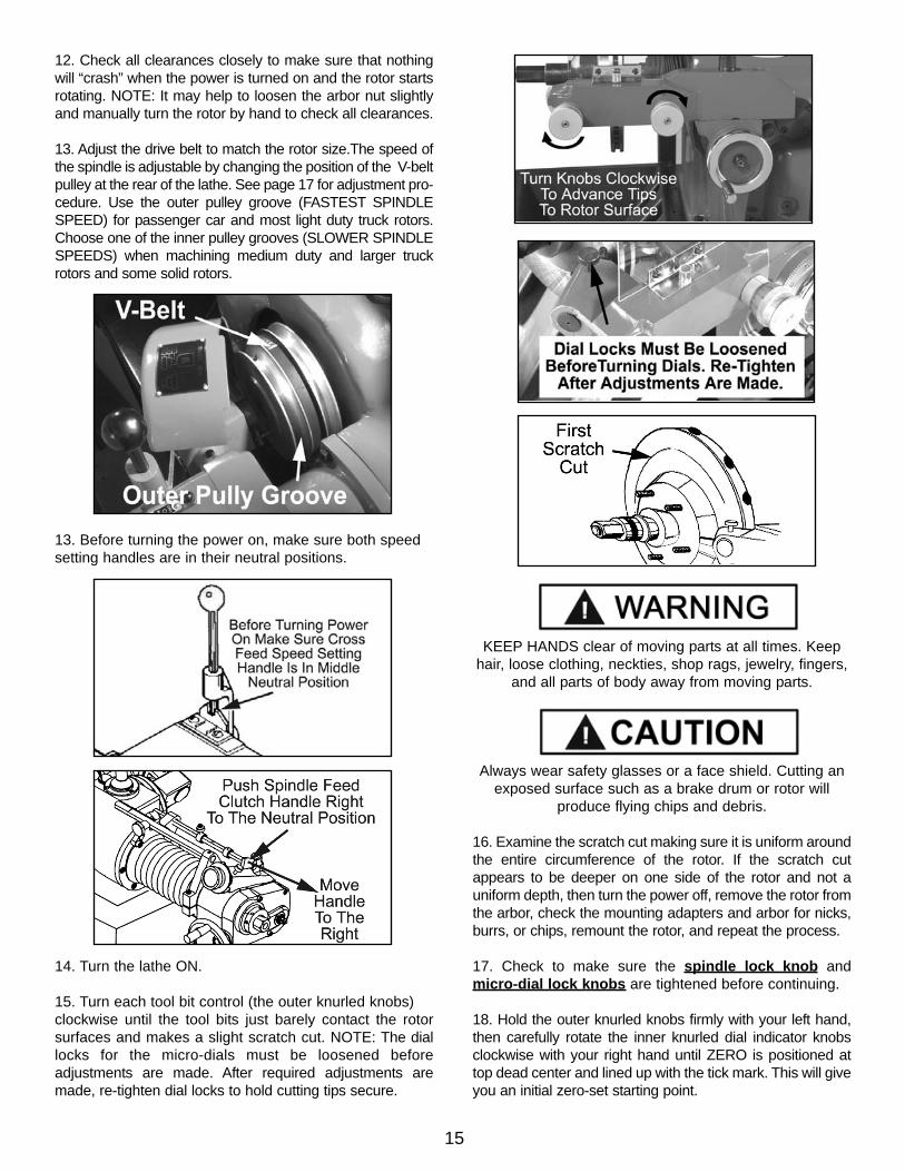
12. Check all clearances closely to make sure that nothingwill “crash” when the power is turned on and the rotor startsrotating. NOTE: It may help to loosen the arbor nut slightlyand manually turn the rotor by hand to check all clearances.
13. Adjust the drive belt to match the rotor size.The speed ofthe spindle is adjustable by changing the position of the V-beltpulley at the rear of the lathe. See page 17 for adjustment pro-cedure. Use the outer pulley groove (FASTEST SPINDLESPEED) for passenger car and most light duty truck rotors.Choose one of the inner pulley grooves (SLOWER SPINDLESPEEDS) when machining medium duty and larger truckrotors and some solid rotors.
13. Before turning the power on, make sure both speedsetting handles are in their neutral positions.
14. Turn the lathe ON.
15. Turn each tool bit control (the outer knurled knobs)clockwise until the tool bits just barely contact the rotorsurfaces and makes a slight scratch cut. NOTE: The diallocks for the micro-dials must be loosened beforeadjustments are made. After required adjustments aremade, re-tighten dial locks to hold cutting tips secure.
KEEP HANDS clear of moving parts at all times. Keephair, loose clothing, neckties, shop rags, jewelry, fingers,
and all parts of body away from moving parts.
Always wear safety glasses or a face shield. Cutting anexposed surface such as a brake drum or rotor will
produce flying chips and debris.
16. Examine the scratch cut making sure it is uniform aroundthe entire circumference of the rotor. If the scratch cutappears to be deeper on one side of the rotor and not auniform depth, then turn the power off, remove the rotor fromthe arbor, check the mounting adapters and arbor for nicks,burrs, or chips, remount the rotor, and repeat the process.
17. Check to make sure the spindle lock knob andmicro-dial lock knobs are tightened before continuing.
18. Hold the outer knurled knobs firmly with your left hand,then carefully rotate the inner knurled dial indicator knobsclockwise with your right hand until ZERO is positioned attop dead center and lined up with the tick mark. This will giveyou an initial zero-set starting point.
15

19. Manually turn the cross feed hand wheelcounterclockwise and move the cutting tools outwardtoward the edge of the rotor to remove any rust build-up orhigh areas on the outer edge.
20. After cleaning up the outer edge of the rotor manuallyfeed the cutting tools inward towards the center of the rotorto a point slightly beyond the contact surface of the brakepads being careful not to run the carbide inserts into thehub portion of the rotor.
21.Turn both tool bit controls (OUTER KNURLEDKNOBS) to the desired depth-of cut then lock them inposition by tightening the dial lock knobs.
USE THESE GENERAL GUIDELINES TO DETERMINE THE DEPTH-OF-CUT
Either rough or finish cuts may be taken to resurface arotor. Generally, finish cuts should be 0.004” (0.10 mm)to 0.006” (0.15 mm) per side. Very shallow cuts of lessthan 0.004” (10 mm) per side tend to reduce tool bit lifebecause the heat generated during reconditioning isn’ttransferred to the rotor efficiently. Rough cuts may be
taken from 0.006” to 0.010” per side.
IMPORTANT NOTEHold OUTER knobs with one hand and turn CLOCK-WISE to move cutting tips inward towards rotor. There
are 10 large graduations on each dial indicator. Each markrepresents 0.002” english ( 0.05 mm metric ).
22. Engage the automatic cross feed to begin the cut bymoving the lever to the desired speed. The cross feed willstop automatically when the cutting tools have moved allthe way across the face of the rotor.
IMPORTANT NOTEFor roughing cuts, move the cross feed lever to the
FAST position. Rough cuts may be taken from 0.006” to0.010” per side.
23. Manually feed the cutting tools inward towards thecenter of the rotor to a point slightly beyond the contactsurface of the brake pads being careful not to run thecarbide inserts into the hub portion of the rotor.
24. Turn the end knob of each tool bar micro-dialindividually to set each tool bit to the desired depth-of cut.Remove only enough material to clean up each side.
25. Engage the automatic cross feed to begin another cut.
26. When the tool bits have cleared the rotor, disengagethe cross feed and turn the lathe OFF.
27. Inspect the brake surfaces. If part of the surface wasnot cut, leave the tool bars locked in position, turn thelathe ON, slowly turn the cross feed handwheel clockwiseuntil the outer tool reaches the groove at the rotor hub,and repeat steps 20 -23.
28. Repeat steps until a smooth finish cut is made.
16
RECONDITIONING FLYWHEELS
Mounting Flywheels1. Clean the machined surfaces, so they are free of rust,dirt and burrs.
2. Mount the flywheel in the same manner as a hublessrotor or drum, with the side to be machined facing thelathe.
IMPORTANT NOTEDowel pins or studs must be removed before machiningcan be performed. Use silencers when possible. Magnet
packs or bars may be used as silencers.
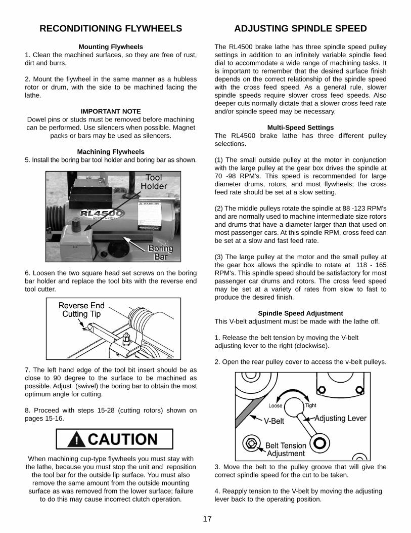
Machining Flywheels5. Install the boring bar tool holder and boring bar as shown.
6. Loosen the two square head set screws on the boringbar holder and replace the tool bits with the reverse endtool cutter.
7. The left hand edge of the tool bit insert should be asclose to 90 degree to the surface to be machined aspossible. Adjust (swivel) the boring bar to obtain the mostoptimum angle for cutting.
8. Proceed with steps 15-28 (cutting rotors) shown onpages 15-16.
When machining cup-type flywheels you must stay withthe lathe, because you must stop the unit and reposition
the tool bar for the outside lip surface. You must alsoremove the same amount from the outside mounting
surface as was removed from the lower surface; failureto do this may cause incorrect clutch operation.
ADJUSTING SPINDLE SPEED
The RL4500 brake lathe has three spindle speed pulleysettings in addition to an infinitely variable spindle feeddial to accommodate a wide range of machining tasks. Itis important to remember that the desired surface finishdepends on the correct relationship of the spindle speedwith the cross feed speed. As a general rule, slowerspindle speeds require slower cross feed speeds. Alsodeeper cuts normally dictate that a slower cross feed rateand/or spindle speed may be necessary.
Multi-Speed SettingsThe RL4500 brake lathe has three different pulleyselections.
(1) The small outside pulley at the motor in conjunctionwith the large pulley at the gear box drives the spindle at70 -98 RPM's. This speed is recommended for largediameter drums, rotors, and most flywheels; the crossfeed rate should be set at a slow setting.
(2) The middle pulleys rotate the spindle at 88 -123 RPM'sand are normally used to machine intermediate size rotorsand drums that have a diameter larger than that used onmost passenger cars. At this spindle RPM, cross feed canbe set at a slow and fast feed rate.
(3) The large pulley at the motor and the small pulley atthe gear box allows the spindle to rotate at 118 - 165RPM's. This spindle speed should be satisfactory for mostpassenger car drums and rotors. The cross feed speedmay be set at a variety of rates from slow to fast toproduce the desired finish.
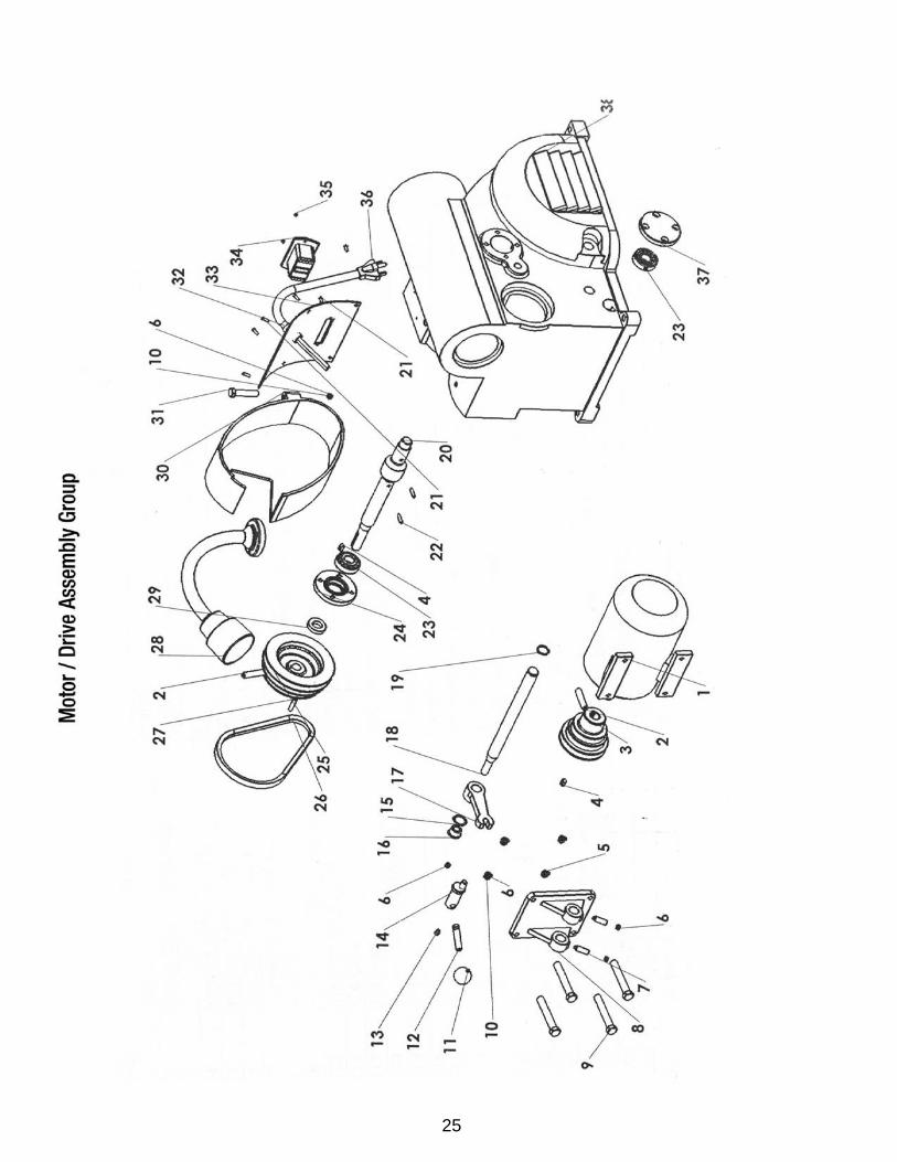
Spindle Speed AdjustmentThis V-belt adjustment must be made with the lathe off.
1. Release the belt tension by moving the V-beltadjusting lever to the right (clockwise).
2. Open the rear pulley cover to access the v-belt pulleys.
3. Move the belt to the pulley groove that will give thecorrect spindle speed for the cut to be taken.
4. Reapply tension to the V-belt by moving the adjustinglever back to the operating position.
17
INSTALLATION INSTRUCTIONS
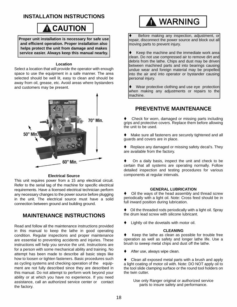
LocationSelect a location that will provide the operator with enoughspace to use the equipment in a safe manner. The areaselected should be well lit, easy to clean and should beaway from oil, grease, etc. Avoid areas where bystandersand customers may be present.
Electrical SourceThis unit requires power from a 15 amp electrical circuit.Refer to the serial tag of the machine for specific electricalrequirements. Have a licensed electrical technician performany necessary changes to the power source before pluggingin the unit. The electrical source must have a solidconnection between ground and building ground.
MAINTENANCE INSTRUCTIONS
Read and follow all the maintenance instructions providedin this manual to keep the lathe in good operatingcondition. Regular inspections and proper maintenanceare essential to preventing accidents and injuries. Theseinstructions will help you service the unit. Instructions arefor a person with some mechanical ability and training. Noattempt has been made to describe all basic steps likehow to loosen or tighten fasteners. Basic procedures suchas cycling systems and checking operation of the equip-ment are not fully described since they are described inthis manual. Do not attempt to perform work beyond yourability or at which you have no experience. If you needassistance, call an authorized service center or contactthe factory.
PREVENTIVE MAINTENANCE
Check for worn, damaged or missing parts includinggrips and protective covers. Replace them before allowingthe unit to be used.
Make sure all fasteners are securely tightened and allguards and covers are in place.
Replace any damaged or missing safety decal’s. Theyare available from the factory.
On a daily basis, inspect the unit and check to becertain that all systems are operating normally. Followdetailed inspection and testing procedures for variouscomponents at regular intervals.
GENERAL LUBRICATION Oil the ways of the head assembly and thread screw
periodically with a light oil. Note: Cross feed should be infull inward position during lubrication.
Oil the threaded rods periodically with a light oil. Spraythe drum lead screw with silicone lubricant.
Lightly oil the dovetails with motor oil.
CLEANING Keep the lathe as clean as possible for trouble free
operation as well as safety and longer lathe life. Use abrush to sweep metal chips and dust off the lathe.
After use, always wipe clean.
Clean all exposed metal parts with a brush and applya light coating of motor oil with. Note: DO NOT apply oil tothe tool slide clamping surface or the round tool holders onthe twin cutter.
Use only Ranger original or authorized serviceparts to insure safety and performance.
18
Before making any inspection, adjustment, orrepair, disconnect the power source and block out allmoving parts to prevent injury.
Keep the machine and the immediate work areaclean. Do not use compressed air to remove dirt anddebris from the lathe. Chips and dust may be drivenbetween machined parts and into bearings causingundue wear and foreign material may be propelledinto the air and into operator or bystander causingpersonal injury.
Wear protective clothing and use eye protectionwhen making any adjustments or repairs to themachine.
Proper unit installation is necessary for safe useand efficient operation. Proper installation alsohelps protect the unit from damage and makesservice easier. Always keep this manual nearby.
19
20

21

22

23

24
25
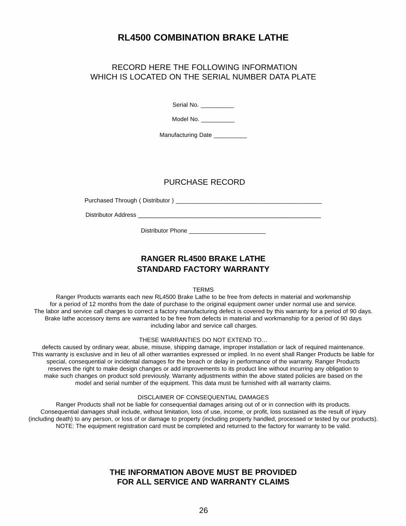
RL4500 COMBINATION BRAKE LATHE
RECORD HERE THE FOLLOWING INFORMATION WHICH IS LOCATED ON THE SERIAL NUMBER DATA PLATE
Serial No. __________
Model No. __________
Manufacturing Date __________
PURCHASE RECORD
Purchased Through ( Distributor ) ____________________________________________
Distributor Address _______________________________________________________
Distributor Phone _______________________
RANGER RL4500 BRAKE LATHESTANDARD FACTORY WARRANTY
TERMSRanger Products warrants each new RL4500 Brake Lathe to be free from defects in material and workmanship
for a period of 12 months from the date of purchase to the original equipment owner under normal use and service. The labor and service call charges to correct a factory manufacturing defect is covered by this warranty for a period of 90 days.
Brake lathe accessory items are warranted to be free from defects in material and workmanship for a period of 90 daysincluding labor and service call charges.
THESE WARRANTIES DO NOT EXTEND TO…defects caused by ordinary wear, abuse, misuse, shipping damage, improper installation or lack of required maintenance.
This warranty is exclusive and in lieu of all other warranties expressed or implied. In no event shall Ranger Products be liable for special, consequential or incidental damages for the breach or delay in performance of the warranty. Ranger Products reserves the right to make design changes or add improvements to its product line without incurring any obligation to
make such changes on product sold previously. Warranty adjustments within the above stated policies are based on the model and serial number of the equipment. This data must be furnished with all warranty claims.
DISCLAIMER OF CONSEQUENTIAL DAMAGESRanger Products shall not be liable for consequential damages arising out of or in connection with its products.
Consequential damages shall include, without limitation, loss of use, income, or profit, loss sustained as the result of injury (including death) to any person, or loss of or damage to property (including property handled, processed or tested by our products).
NOTE: The equipment registration card must be completed and returned to the factory for warranty to be valid.
THE INFORMATION ABOVE MUST BE PROVIDED FOR ALL SERVICE AND WARRANTY CLAIMS
26
27

For Parts Or ServiceContact:
Bend-Pak Inc. / Ranger Products1645 Lemonwood Dr.
Santa Paula, CA. 93060
Tel: 1-805-933-9970Fax: 1-805-933-9160
www.bendpak.comwww.rangerproducts.com