mitel sx200 ons integration using dialogic media gateways sx-200... · mitel sx200 ons integration...
TRANSCRIPT

Rev date: 05/22/12
Innovation Voice Mail PBX Installation and Testing Guide
Mitel SX200 ONS Integration using Dialogic Media Gateways
1841 Bourbon Road
Cross Plains, Wisconsin 1-800-424-6757
www.innovationtw.com
Innovation Voice Mail PBX Installation and Testing Guide
1
Mitel SX-200 ONS Integration REQUIREMENTS: ♦ If G1004 series, revision E23 or higher is required. ♦ If G1005 (LW15), revision F19 or higher is required ♦ LW16 or higher is fully supported. ♦ An ONS station for each voicemail port. ♦ An analog station (or dedicated CO line) for the system’s modem. ♦ One Dialogic DMG1008LSW gateway for every 8 analog ports PBX PROGRAMMING: System Option Programming – Form 04 Set the following system options as specified:
Enable Option 21 (INCOMING TO OUTGOING CALL FORWARD) Enable Option 22 (LAST PARTY CLEAR-DIAL TONE)1 Enable Option 38 (SWITCH-HOOK FLASH) Set MINIMUM FLASH TIMER to 20 Set MAXIMUM FLASH TIMER to 100
Voicemail COS Programming – Form 03 Enable the following options in the ONS voice mail line COS:
Enable Option 212 (CAN FLASH IF TALKING TO AN INCOMING TRUNK) Enable Option 213 (CAN FLASH IF TALKING TO AN OUTGOING TRUNK) Enable Option 216 (DATA SECURITY) Enable Option 220 (DO NOT DISTURB) Enable Option 238 (OVERRIDE SECURITY) Enable Option 239 (PRIORITY DIAL 0) – Optional Enable Option 259 (MESSAGE SENDING) Enable Option 261 (ONS VOICE MAIL PORT) (Newer 200ICP systems) – Set Option 506 (ONS POSITIVE DISCONNECT) to a value of 3.
If this option number is present on your system, then System Option 22 (LAST PART CLEAR-DIAL TONE) does not need to be enabled
Voicemail COS Programming – Form 09 Create a new ONS station for each voicemail port in this form. Assign the COS you created for voicemail to these stations. Voicemail Hunt Group Programming – Form 17 Place all the ONS voicemail stations in a hunt group. ONS stations that will perform outdial functions (message waiting, wake-up calls, call and pager notification) should be placed in DO NOT DISTURB. Another method is to have all outdial stations in there own hunt group. This is a necessity if you plan to have more than one station issue message waiting commands.
1 Check first if your Mitel SX-200 supports COS Option 506 first. If not, then enable system option 22 to use dial tone for disconnect.

Innovation Voice Mail PBX Installation and Testing Guide
2
Voicemail User COS Programming – Form 03 Enable the following COS options for all voice mail users:
Enable Option 206 (CALL FORWARDING – BUSY) Enable Option 207 (CALL FORWARDING – DON’T ANSWER) Enable Option 208 (CALL FORWARDING – EXTERNAL) Enable Option 232 (MESSAGE WAITING SETUP – LAMP) Enable Option 245 (ABBREVIATED DIALING ACCESS)
Feature Access Code Programming – Form 02 Assign a feature access code to the following feature numbers:
Feature Number 03 (CALL FORWARDING – ALL CALLS) – Optional Feature Number 24 (ABBREVIATED DIAL ACCESS) Feature Number 41 (SEND MESSAGE)
System Abbreviated Dial Programming – Form 31 Special codes need to be entered in this form. They control what in-band DTMF digits the SX-200 generates to the voicemail system. For Message Retrieval: Create or modify an existing index number (such as “6” for example), and enter the following digit string: XXX*91*6 XXX = Hunt Group Access Code *9 = One second pause 1 = Identifies the call as a direct call to voicemail *6 = Tones out the calling parties station number For Message Forward: Create or modify an existing index number (such as “999” for example), and enter the following digit string: XXX*90*6***8 XXX = Hunt Group Access Code *9 = One second pause 0 = Identifies the call as a call forwarded call to voicemail *6 = Tones out the called parties station number ** = Separator digit *8 = Tones out the calling parties station number

Innovation Voice Mail PBX Installation and Testing Guide
3
Form 31 programming example: The example shown below assumes that 520 is the Hunt Group access code to the voicemail ONS stations:
If 6 is your abbreviated dial access code, voicemail users would dial 66 to access voicemail. All stations would be forwarded on a busy and no answer to 6999. In the event that your Mitel PBX (Typically ones that are G1004) DOES NOT support the separator digit (**) and the ability to tone out the calling parties’ station number (*8), program your digit strings as shown in the example below:
The *9 at the end of each digit string may (or may not) be needed. Sometimes the older SX-200’s needed an extra one second pause to finish sending the in-band digits. Testing your call integration will determine if this one second pause at the end is required. Other Items • Enabling Option 320 (TRANSPARENT MULTI-CONSOLE OPERATION) in the attendant
console’s COS will allow you to view what device turned a message lamp on. This could be helpful in the event devices other than the voicemail hunt group turned on a stations message indicator, and you need to troubleshoot this issue.
• Enable Option 119 (ATTENDANT TONE SIGNALING) in the attendant console’s COS. This
will allow the console user to turn TONES ON (F0 key) and interact with the voice mail. • Create a LDN DIR NUMBER and label as VMAIL DIAL 0. By using the Priority Dial 0 routing
feature in FORM 19, you can route dial 0 calls from voice mail to an F key on the attendant console. Remember to enable Option 239 (PRIORITY DIAL 0) in the ONS voice mail stations COS if you plan on doing this.
• Create a LDN DIR NUMBER and label as VM OVERFLOW. Enter this LDN DIR NUMBER in
the Overflow section of FORM 17, under “options”. This will allow direct or forwarded calls to voice mail to overflow to an F key on the attendant console, if all voice mail stations are busy.
• Forward each voice mail station on a no answer to a LDN DIR NUMBER appearance on the
attendant console. Label as VMAIL OFF! This will allow direct or forwarded calls to the voice mail to ring at the attendant console if the voice mail system is off-line.
• Do not program any station number (such as an attendant LDN) in the field: “Station illegal
number routing for this tenant”. This is located in FORM 19 – Call Rerouting Table. During database swaps with a PMS, the voicemail will send the “lamp-off” code for each check-out resync message it receives, even if the lamp is currently off. If a station number is programmed in the “station illegal…” field, the SX-200 will ring this station for each lamp off code dialed by the voice mail.

Innovation Voice Mail PBX Installation and Testing Guide
4
NETWORK CONNECTIONS: INSTALLATIONS WITH ONE GATEWAY (8 ports or less) On the back of the InnLine IP voicemail system, connect a network cable from the top left hand corner network jack, and connect it directly to the LAN network connector on the DMG1008LSW media gateway. The IP addresses for each device are ITW default settings.
(192.168.210.2)
(Mitel ONS analog stations 1 – 8) / (192.168.210.10)

Innovation Voice Mail PBX Installation and Testing Guide
5
INSTALLATIONS WITH MULTIPLE GATEWAYS (more than 8 ports) Connect a network cable from the top left hand corner network jack, and connect it to the jack labeled #5 of the NETGEAR switch. Then connect another network cable from the jack labeled #1 on the NETGEAR switch to the LAN network jack on the Dialogic DMG1008LSW media gateway. Repeat the connections from the NETGEAR switch (#2 through #4) for connecting your additional media gateways. The example below shows connectivity for a 32 port system. The IP addresses for each device are ITW default settings.
(192.168.210.2)
(Mitel ONS analog stations 1 – 8) / (192.168.210.10)
(Mitel ONS analog stations 9 – 16) / (192.168.210.11)
(Mitel ONS analog stations 17 – 24) / (192.168.210.12)
(Mitel ONS analog stations 25 – 32 / (192.168.210.13)

Innovation Voice Mail PBX Installation and Testing Guide
6
PBX TERMINATIONS: The Dialogic DMG1008LSW has 8 RJ14 style connectors on the back. Connect the Mitel ONS analog stations to the gateway’s RJ14 jacks numbered 1 through 8 using standard line cords.
As you connect each line cord, the Port Status led indicator for that line will change from red to green. This indicates that Carrier is present.
Port Status definitions:
• Steady Green – indicates that Carrier is present. • Flashing Green – indicates that there is activity on the port. • Steady Yellow – Hardware Carrier is present, but no software communication. • Flashing Yellow – External power detected, but port cannot gain carrier • Steady Red – Indicates that no Carrier is present and no external power detected

Innovation Voice Mail PBX Installation and Testing Guide
7
VOICEMAIL PROGRAMMING:
InnLine IP Configuration Utility (IIPConfig) On the desktop, open the file InnLine IP Config and review the following information:
Local IP Address: This field displays the static IP Address assigned to the InnLine IP voicemail. SIP Proxy Address: This is the IP Address of the first Dialogic Media Gateway. The default value is 192.168.210.10. SIP Password: This is the password that is programmed for each Mitel ONS analog station that is connected to the media gateway(s). Authentication Realm: This is the realm name that is referenced for each of the Mitel ONS analog stations that are connected to the media gateway(s) If you have changed anything, click Save, then Cancel to exit. In order for these changes to take, you must stop InnLine IP application, and then re-start it (by double-clicking the InnLine IP icon located on the desktop.

Innovation Voice Mail PBX Installation and Testing Guide
8
Voice Port Configuration – single gateway Go to Do > Configure System > Voice Ports and double the Port Wizard (choose Yes to run the port wizard at this time
If your Mitel ONS analog stations are concurrent, enter the first number in BOTH the 1st Extension and Sip Alias fields. Click OK. The port wizard will now automatically populate these fields in the other Port Screens IMPORTANT NOTE: The last port is always set to Out-Bound only. This port needs to be protected from inbound calls. Put that Mitel ONS analog station into DND. If you require additional ports to perform outbound events, then these Mitel ONS analog stations need to be put into DND as well.
Innovation Voice Mail PBX Installation and Testing Guide
9
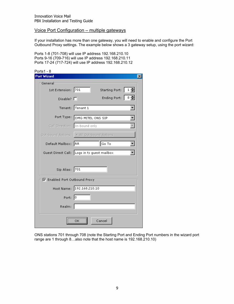
Voice Port Configuration – multiple gateways If your installation has more than one gateway, you will need to enable and configure the Port Outbound Proxy settings. The example below shows a 3 gateway setup, using the port wizard: Ports 1-8 (701-708) will use IP address 192.168.210.10 Ports 9-16 (709-716) will use IP address 192.168.210.11 Ports 17-24 (717-724) will use IP address 192.168.210.12 Ports1 - 8
ONS stations 701 through 708 (note the Starting Port and Ending Port numbers in the wizard port range are 1 through 8…also note that the host name is 192.168.210.10)

Innovation Voice Mail PBX Installation and Testing Guide
10
Ports 9 - 16
ONS stations 709 through 716 (note the Starting Port and Ending Port numbers in the wizard port range are 9 through 16…also note that the host name is 192.168.210.11)

Innovation Voice Mail PBX Installation and Testing Guide
11
Ports 17-24
ONS stations 717 through 724 (note the Starting Port and Ending Port numbers in the wizard port range are 17 through 24…also note that the Port Outbound Proxy does not need to be enabled). The IP address 192.168.210.12 of the third gateway will be referenced in the IIP Config utility’s SIP Proxy Address field:

Innovation Voice Mail PBX Installation and Testing Guide
12
DIALOGIC MEDIA GATEWAY PROGRAMMING: You will need to program your ONS station numbers into each media gateway. Open a web browser, and connect to 192.168.210.10 as shown below:
Enter the following user credentials - User name: admin Password: innlineip
On the left hand side of the web page, under Configuration, browse to VoIP > Authentication

Innovation Voice Mail PBX Installation and Testing Guide
13
VOIP Authentication configuration – single gateway (192.168.210.10) Program all eight voicemail ONS stations in each of the User Name fields. DO NOT change the Password information. Click the Submit button when done. The screen shot below shows an example of ONS stations 701 through 708: 192.168.210.10 (Ports 1 – 8) – FIRST GATEWAY

Innovation Voice Mail PBX Installation and Testing Guide
14
VOIP Authentication configuration – multiple gateways If you have a second gateway, the next eight ONS stations (example shown is 709 through 716) will be programmed into the 192.168.210.11 gateway. If you have a third, the next eight ONS stations (example shown is 717 through 724) are programmed into the 192.168.210.12 gateway. Use this numbering scheme for additional gateways. 192.168.210.11 (Ports 9 – 16) – SECOND GATEWAY

Innovation Voice Mail PBX Installation and Testing Guide
15
192.168.210.12 (Ports 17 – 24) – THIRD GATEWAY

Innovation Voice Mail PBX Installation and Testing Guide
16
TESTING: Testing disconnect supervision When a caller is connected to voicemail and hangs up, dial tone is presented immediately to the ONS voice mail port. This is the systems indication to disconnect. Test this by placing a call from a station (configured as a staff mailbox) to the voicemail system. After voicemail answers, hang up. The voicemail port should return to a wait for call… state. If the call stays connected, and only hangs up after 3 menu iterations, then dial tone isn’t being returned to the ONS station port. If disconnect supervision does not work, make sure that System Option 22 (LAST PARTY CLEAR – DIAL TONE) is enabled. For a trunk to station test, call the hotel’s main number, and have the attendant transfer you to voicemail. When voicemail answers, hang-up and watch for the loop current drop detected message to be displayed. Testing direct call integration (From any station) From any station (guest or staff), place a call to the abbreviated dial feature number and index number that was programmed for Message Retrieval. The activity window will show what station number is calling. (Example below shows staff extension 699 calling the voicemail access code) 001 << DIRECT CALL FROM 699 >> 001 play 513 008 call *412699 001 wait for call... Testing call forward integration Call forward one guest extension on a “busy/no answer” to the abbreviated dial feature number and index number that was programmed for Message Forward for this test. Call forwarding may be programmed from the attendant console (provided it’s COS allows this function), or from the station itself. From a staff extension, call the guest extension, allowing it to forward to voicemail. The information will show both the calling and called party. 003 << FORWARDED CALL FROM 7112 DIALED BY 699 >> 003 play GUNA 003 wait for call... Perform this forwarding test via a trunk as well.

Innovation Voice Mail PBX Installation and Testing Guide
17
Testing message lamps To test message lamps, enter the SEND MESSAGE feature access code in both Dial String Prefix fields of the Indicator On and Indicator Off sections, found under the MWI tab of the Mitel ONS port type. In the example below, *41 is the SEND MESSAGE feature code, followed by a 1 for ON, or a 2 for OFF.
Check under FORM 02 in the Mitel SX-200 programming to verify that you entered the correct SEND MESSAGE code.
Innovation Voice Mail PBX Installation and Testing Guide
18
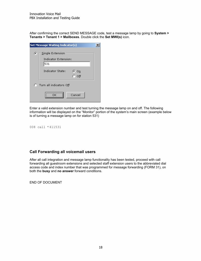
After confirming the correct SEND MESSAGE code, test a message lamp by going to System > Tenants > Tenant 1 > Mailboxes. Double click the Set MWI(s) icon.
Enter a valid extension number and test turning the message lamp on and off. The following information will be displayed on the “Monitor” portion of the system’s main screen (example below is of turning a message lamp on for station 531) 008 call *411531 Call Forwarding all voicemail users After all call integration and message lamp functionality has been tested, proceed with call forwarding all guestroom extensions and selected staff extension users to the abbreviated dial access code and index number that was programmed for message forwarding (FORM 31), on both the busy and no answer forward conditions. END OF DOCUMENT