miscellaneous electrical materials
TRANSCRIPT
9.1 Thermocouple Materials
9.1.1 The Seebeck Effect
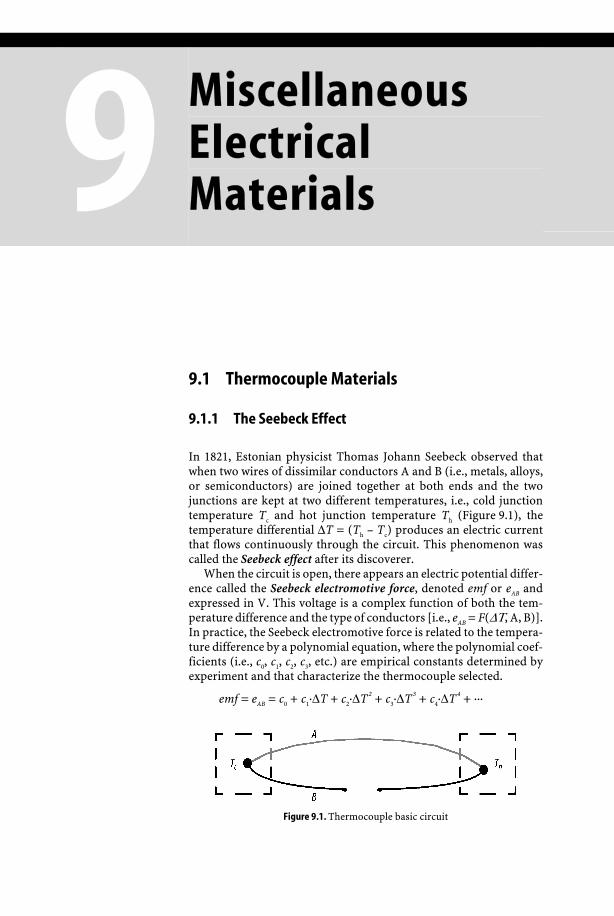
In 1821, Estonian physicist Thomas Johann Seebeck observed that when two wires of dissimilar conductors A and B (i.e., metals, alloys, or semiconductors) are joined together at both ends and the two junctions are kept at two different temperatures, i.e., cold junction temperature Tc and hot junction temperature Th (Figure 9.1), the temperature differential ΔT = (Th – Tc) produces an electric current that flows continuously through the circuit. This phenomenon was called the Seebeck effect after its discoverer.
When the circuit is open, there appears an electric potential differ-ence called the Seebeck electromotive force, denoted emf or eAB and expressed in V. This voltage is a complex function of both the tem-perature difference and the type of conductors [i.e., eAB = F(ΔΤ, A, B)]. In practice, the Seebeck electromotive force is related to the tempera-ture difference by a polynomial equation, where the polynomial coef-ficients (i.e., c0, c1, c2, c3, etc.) are empirical constants determined by experiment and that characterize the thermocouple selected.
emf = eAB = c0 + c1·ΔT + c2·ΔT 2 + c3·ΔT 3 + c4·ΔT 4 + ···
Figure 9.1. Thermocouple basic circuit
Miscellaneous Electrical Materials
544 Miscellaneous Electrical Materials
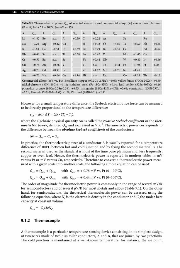
Table 9.1. Thermoelectric power QAB of selected elements and commercial alloys (A) versus pure platinum (B = Pt) for a ΔT = 100°C (in mV vs. Pt)
A QAB A QAB A QAB A QAB A QAB A QAB A QAB
Li +1.82 Be n.a. Al +0.39 C +0.22 As Se Ru
Na –0.20 Mg +0.42 Ga Si +44.8 Sb +4.89 Te +50.0 Rh +0.65
K –0.83 Ca –0.51 In +0.69 Ge +33.9 Bi –7.34 Cr Pd –0.47
Rb +0.46 Sr n.a. Tl +0.58 Sn +0.42 V Mo +1.45 Os
Cs +0.50 Ba n.a. Sc Pb +0.44 Nb W +0.80 Ir +0.66
Cu +0.75 Zn +0.76 Y Ti n.a. Ta +0.41 Fe +1.98 Pt 0.00
Ag +0.73 Cd +0.91 La Zr +1.17 Mn +0.70 Ni –1.48 U
Au +0.70 Hg +0.06 Ce +1.14 Hf n.a. Re Co –1.33 Th –0.13
Commercial alloys (mV vs. Pt): Beryllium-copper (97.3Cu-2.7Be): +0.67; yellow brass (70Cu-30Zn): +0.60; nickel-chrome (80Ni-20Cr): +1.14; stainless steel (Fe-18Cr-8Ni): +0.44; lead solder (50Sn-50Pb): +0.46; phosphor bronze (96Cu-3.5Sn-0.3P): +0.55; manganin (84Cu-12Mn-4Ni): +0.61; constantan (45Ni-55Cu): –3.51; Alumel (95Ni-2Mn-2Al): –1.29; Chromel (90Ni-9Cr): +2.81.
However for a small temperature difference, the Seebeck electromotive force can be assumed to be directly proportional to the temperature difference:
eAB = Δα · ΔT = Δα · (Th – Tc),
where the algebraic physical quantity Δα is called the relative Seebeck coefficient or the ther-moelectric power, denoted QAB and expressed in V.K–1. Thermoelectric power corresponds to the difference between the absolute Seebeck coefficients of the conductors:
Δα = QAB = αA – αB.
In practice, the thermoelectric power of a conductor A is usually reported for a temperature difference of 100°C between hot and cold junction and by fixing the second material B. The second material used as the standard is most of the time pure platinum and, less frequently, copper or even lead. Hence, the thermoelectric power is reported in modern tables in mV versus Pt or mV versus Cu, respectively. Therefore to convert a thermoelectric power meas-ured with a given scale into another scale, the following simple equation can be used:
QAPt = QACu + QCuPt with QCuPt = + 0.75 mV vs. Pt (0–100°C),
QAPt = QAPb + QPbPt with QPbPt = + 0.44 mV vs. Pt (0–100°C).
The order of magnitude for thermoelectric power is commonly in the range of several mV/K for semiconductors and of several μV/K for most metals and alloys (Table 9.1). On the other hand, for semiconductors, the theoretical thermoelectric power can be assessed using the following equation, where Ne is the electronic density in the conductor and Cv the molar heat capacity at constant volume:
QAB = –Cv /3eNe.
9.1.2 Thermocouple
A thermocouple is a particular temperature-sensing device consisting, in its simplest design, of two wires made of two dissimilar conductors, A and B, that are joined by two junctions. The cold junction is maintained at a well-known temperature, for instance, the ice point,

Thermocouple Materials 545
9 Miscel-laneous
Electrical Materials
while the other junction serves as probe. The electromotive force measured with a high-precision voltmeter is then proportional to the temperature of the hot junction. The signal can even be amplified by connecting in series n identical thermocouples (Figure 9.2).
The resulting overall electromotive force ΔV is the sum of all the individual emf of each thermocouple and is easier to measure with accuracy:
ΔV = QAB · ΔT + QAB · ΔT2 + QAB · ΔT3 + QAB · ΔT4 + ··· + QAB · ΔTn = QAB · ∑kΔTk.
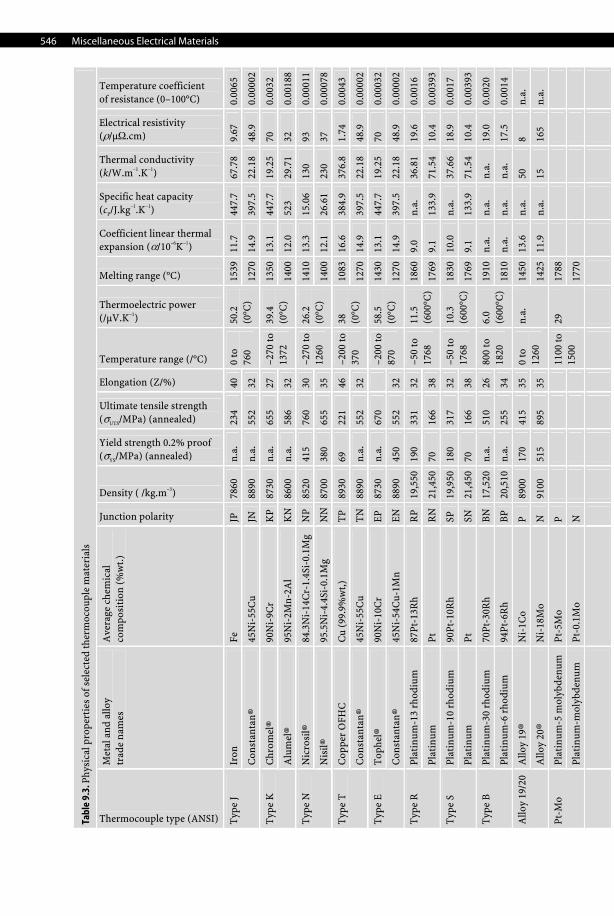
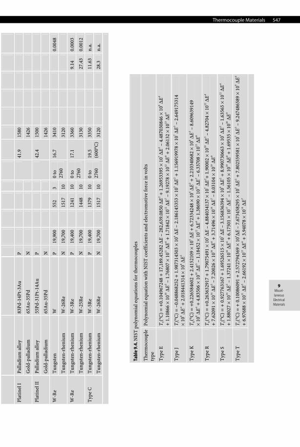
9.1.3 Properties of Common Thermocouple Materials
Table 9.2. Standard thermocouple types and common uses
Type Description
Type J Suitable in reducing, vacuum, or inert atmospheres but limited use in oxidizing atmosphere at high temperature. Not recommended for low temperatures.
Type K Clean and oxidizing atmospheres, limited use in vacuum or reducing atmospheres. Wide temperature range.
Type S Oxidizing or inert atmospheres. Beware of contamination. For high temperatures.
Type R Oxidizing or inert atmospheres. Beware of contamination. For high temperatures.
Type N More stable than type K at high temperature.
Type B Oxidizing or inert atmospheres. Beware of contamination. For high temperatures.
Type E Oxidizing or inert atmospheres, limited use in vacuum or reducing atmospheres. Highest thermoelectric power.
Type C Suitable in reducing, vacuum, or inert atmospheres. Beware of embrittlement. Not suitable for oxidizing atmospheres and not practical below 400°C.
Type T Suitable in mid-oxidizing, reducing, vacuum, or inert atmospheres. Good for cryogenic applications.
Figure 9.2. Thermocouples in series
546 Miscellaneous Electrical Materials
Ta
ble
9.3.
Phy
sica
l pro
pert
ies
of s
elec
ted
ther
moc
oupl
e m
ater
ials
Thermocouple type (ANSI)
Met
al a
nd a
lloy
tr
ade
nam
es
Ave
rage
che
mic
al
com
posi
tion
(%
wt.
)
Junction polarity
Density ( /kg.m–3)
Yield strength 0.2% proof (σYS/MPa) (annealed)
Ultimate tensile strength (σUTS/MPa) (annealed)
Elongation (Z/%)
Temperature range (/°C)
Thermoelectric power (/μV.K–1)
Melting range (°C)
Coefficient linear thermal expansion (α/10–6K–1)
Specific heat capacity (cP/J.kg–1.K–1)
Thermal conductivity (k/W.m–1.K–1)
Electrical resistivity (ρ/μΩ.cm)
Temperature coefficient of resistance (0–100°C)
Iron
Fe
JP
78
60
n.a.
23
4 40
15
39
11.7
44
7.7
67.7
8 9.
67
0.00
65
Typ
e J
Con
stan
tan
® 45
Ni-
55C
u JN
88
90
n.a.
55
2 32
0 to
76
0 50
.2
(0°C
) 12
70
14.9
39
7.5
22.1
8 48
.9
0.00
002
Chr
omel
® 90
Ni-
9Cr
KP
8730
n.
a.
655
27
1350
13
.1
447.
7 19
.25
70
0.00
32
Typ
e K
Alu
mel
® 95
Ni-
2Mn-
2Al
KN
8600
n.
a.
586
32
–270
to
1372
39
.4
(0°C
) 14
00
12.0
52
3 29
.71
32
0.00
188
Nic
rosi
l®
84.3
Ni-
14C
r-1.
4Si-
0.1M
g N
P 85
20
415
760
30
1410
13
.3
15.0
6 13
0 93
0.
0001
1T
ype
N
Nis
il®
95.5
Ni-
4.4S
i-0.
1Mg
NN
8700
38
0 65
5 35
–270
to
1260
26
.2
(0°C
) 14
00
12.1
26
.61
230
37
0.00
078
Cop
per
OFH
C
Cu
(99.
9%w
t,)
TP
8930
69
22
1 46
10
83
16.6
38
4.9
376.
8 1.
74
0.00
43
Typ
e T
Con
stan
tan
® 45
Ni-
55C
u T
N
8890
n.
a.
552
32
–200
to
370
38
(0°C
) 12
70
14.9
39
7.5
22.1
8 48
.9
0.00
002
Top
hel®
90
Ni-
10C
r EP
87
30
n.a.
67
0
1430
13
.1
447.
7 19
.25
70
0.00
032
Typ
e E
Con
stan
tan
® 45
Ni-
54C
u-1M
n EN
88
90
450
552
32
–200
to
870
58.5
(0
°C)
1270
14
.9
397.
5 22
.18
48.9
0.
0000
2
Plat
inum
-13
rhod
ium
87
Pt-1
3Rh
RP
19,5
5019
0 33
1 32
18
60
9.0
n.a.
36
.81
19.6
0.
0016
T
ype
R
Plat
inum
Pt
R
N
21,4
5070
16
6 38
–50
to
1768
11
.5
(600
°C)
1769
9.
1 13
3.9
71.5
4 10
.4
0.00
393
Plat
inum
-10
rhod
ium
90
Pt-1
0Rh
SP
19,9
5018
0 31
7 32
18
30
10.0
n.
a.
37.6
6 18
.9
0.00
17
Typ
e S
Plat
inum
Pt
SN
21
,450
70
166
38
–50
to
1768
10
.3
(600
°C)
1769
9.
1 13
3.9
71.5
4 10
.4
0.00
393
Plat
inum
-30
rhod
ium
70
Pt-3
0Rh
BN
17
,520
n.a.
51
0 26
19
10
n.a.
n.
a.
n.a.
19
.0
0.00
20
Typ
e B
Plat
inum
-6 r
hodi
um
94Pt
-6R
h B
P 20
,510
n.a.
25
5 34
800
to
1820
6.
0
(600
°C)
1810
n.
a.
n.a.
n.
a.
17.5
0.
0014
Allo
y 19
® N
i-1C
o P
8900
17
0 41
5 35
14
50
13.6
n.
a.
50
8 n.
a.
Allo
y 19
/20
Allo
y 20
® N
i-18
Mo
N
9100
51
5 89
5 35
0 to
12
60
n.a.
1425
11
.9
n.a.
15
16
5 n.
a.
Plat
inum
-5 m
olyb
denu
m
Pt-5
Mo
P
17
88
Pt
-Mo
Plat
inum
-mol
ybde
num
Pt
-0.1
Mo
N
1100
to
1500
29
1770
Thermocouple Materials 547
9 Miscel-laneous
Electrical Materials
Palla
dium
allo
y 83
Pd-1
4Pt-
3Au
P
15
80
Pl
atin
el I
Gol
d-pa
lladi
um
65A
u-35
Pd
N
41
.9
1426
Palla
dium
allo
y 55
Pd-3
1Pt-
14A
u P
1500
Plat
inel
II
Gol
d-pa
lladi
um
65A
u-35
Pd
N
42
.4
1426
Tun
gste
n W
P
19,9
00
552
3 34
10
0.00
48
W-R
e
Tun
gste
n-rh
eniu
m
W-2
6Re
N
19,7
00
1517
10
0 to
27
60
16.7
3120
Tun
gste
n-rh
eniu
m
W-3
Re
P 19
,400
12
41
10
3360
9.14
0.
0003
W
-Re
Tun
gste
n-rh
eniu
m
W-2
5Re
N
19,7
00
1448
10
0 to
27
60
17.1
3130
27.4
3 0.
0012
Tun
gste
n-rh
eniu
m
W-5
Re
P 19
,400
13
79
10
3350
11.6
3 n.
a.
Typ
e C
Tun
gste
n-rh
eniu
m
W-2
6Re
N
19,7
00
1517
10
0 to
27
60
19.5
(6
00°C
) 31
20
28
.3
n.a.
Tabl
e 9.
4. N
IST
pol
ynom
ial e
quat
ions
for
ther
moc
oupl
es
The
rmoc
oupl
e
type
Po
lyn
omia
l equ
atio
n w
ith
NIS
T c
oeff
icie
nts
and
elec
trom
otiv
e fo
rce
in v
olts
Typ
e E
T
E(°
C)
= +
0.10
4967
248
+ 1
7,18
9.45
282
ΔE –
282
,639
.085
0 ΔE
2 + 1
.269
5339
5 ×
107 Δ
E 3 –
4.4
8703
0846
× 1
08 ΔE
4 +
1.1
0866
× 1
010 Δ
E 5 –
1.7
6807
× 1
011 Δ
E 6 +
1.7
1842
× 1
012 Δ
E 7 –
9.1
9278
× 1
012 Δ
E 8 +
2.0
6132
× 1
013 Δ
E 9
Typ
e J
TJ(°
C)
= –
0.04
8868
252
+ 1
.987
3145
03 ×
104 Δ
E –
2.18
6145
353
× 10
5 ΔE
2 + 1
.156
9199
78 ×
107 Δ
E 3 –
2.6
4917
5314
×
108 Δ
E 4 +
2.0
1844
1314
× 1
08 ΔE
5
Typ
e K
T
K(°
C)
= +
0.22
6584
602
+ 2
.415
2109
× 1
04 ΔE
+ 6
.723
3424
8 ×
104 Δ
E 2 +
2.2
1034
0682
× 1
06 ΔE
3 – 8
.609
6391
49
× 10
8 ΔE
4 + 4
.835
06 ×
1010
ΔE
5 – 1
.184
52 ×
1012
ΔE
6 + 1
.386
90 ×
1013
ΔE
7 – 6
.337
08 ×
1013
ΔE
8
Typ
e R
T
R(°
C)
= +
0.26
3632
917
+ 1
.790
7549
1 ×
105 Δ
E –
4.88
4034
137
× 10
7 ΔE
2 + 1
.900
02 ×
1010
ΔE
3 – 4
.827
04 ×
1012
ΔE
4 +
7.6
2091
× 1
014 Δ
E 5 –
7.2
0026
× 1
016 Δ
E 6 +
3.7
1496
× 1
018 Δ
E 7 –
8.0
3104
× 1
019 Δ
E 8
Typ
e S
TS(
°C)
= +
0.9
2776
3167
+ 1
.695
2651
5 ×
105 Δ
E –
3.15
6836
394
× 10
9 ΔE
2 + 8
.990
7306
63 ×
109 Δ
E 3 –
1.6
3565
× 1
012 Δ
E 4
+ 1
.880
27 ×
1014
ΔE
5 – 1
.372
41 ×
1016
ΔE
6 + 6
.175
01 ×
1017
ΔE
7 – 1
.561
05 ×
1019
ΔE
8 + 1
.695
35 ×
1020
ΔE
9
Typ
e T
T
T(°
C)
= +
0.1
0086
091
+ 2
.572
7943
69 ×
104 ΔE
– 7
.673
4582
95 ×
105 Δ
E 2 +
7.8
0255
9581
× 1
07 ΔE
3 – 9
.247
4865
89 ×
109 Δ
E 4
+ 6
.976
88 ×
1011
ΔE
5 – 2
.661
92 ×
1013
ΔE
6 + 3
.940
78 ×
1014
ΔE
7
548 Miscellaneous Electrical Materials
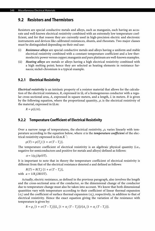
9.2 Resistors and Thermistors
Resistors are special conductive metals and alloys, such as manganin, each having an accu-rate and well-known electrical resistivity combined with an extremely low temperature coef-ficient, and for that reason they are currently used in high-precision electric and electronic instruments and devices like calibrated resistances, shunts, and rheostats. Two major classes must be distinguished depending on their end use:
(i) Resistance alloys are special conductive metals and alloys having a uniform and stable electrical resistivity combined with a constant temperature coefficient and a low ther-moelectric power versus copper; manganin and pure platinum are well-known examples.
(ii) Heating alloys are metals or alloys having a high electrical resistivity combined with a high melting point; hence they are selected as heating elements in resistance fur-naces; nickel-chromium is a typical example.
9.2.1 Electrical Resistivity
Electrical resistivity is an intrinsic property of a resistor material that allows for the calcula-tion of the electrical resistance, R, expressed in Ω, of a homogeneous conductor with a regu-lar cross-sectional area, A, expressed in square meters, and a length, L in meters. R is given by the following equation, where the proportional quantity, ρ, is the electrical resistivity of the material, expressed in Ω.m:
R = ρ(L/A).
9.2.2 Temperature Coefficient of Electrical Resistivity
Over a narrow range of temperatures, the electrical resistivity, ρ, varies linearly with tem-perature according to the equation below, where α is the temperature coefficient of the elec-trical resistivity expressed in Ω.m.K–1:
ρ(T) = ρ(T0) [1 + α (T – T0)].
The temperature coefficient of electrical resistivity is an algebraic physical quantity (i.e., negative for semiconductors and positive for metals and alloys) defined as follows:
α = 1/ρ0(∂ρ/∂T).
It is important to note that in theory the temperature coefficient of electrical resistivity is different from that of the electrical resistance denoted a and defined as follows:
R(T) = R(T0) [1 + a (T – T0)], with a = 1/R0(∂R/∂T).
Actually, electric resistance, as defined in the previous paragraph, also involves the length and the cross-sectional area of the conductor, so the dimensional change of the conductor due to temperature change must also be taken into account. We know that both dimensional quantities vary with temperature according to their coefficient of linear thermal expansion (αL) and the coefficient of surface thermal expansion (αS), respectively, in addition to that of electrical resistivity. Hence the exact equation giving the variation of the resistance with temperature is given by:
R = ρ0 [1 + α (T – T0)]{L0 [1 + αL (T – T0)]}/{A0 [1 + αS (T – T0)]}.

Resistors and Thermistors 549
9 Miscel-laneous
Electrical Materials
Tabl
e 9.
5. R
esis
tors
use
d in
ele
ctri
cal a
nd e
lect
roni
c de
vice
s (s
hunt
s an
d rh
eost
ats)
Resistor material (composition)
Density (ρ/kg.m–3)
Yield strength (σYS/MPa)
Ultimate tensile strength (σUTS/MPa)
Elongation (Z/%)
Thermal conductivity (k/Wm–1K–1)
Specific heat capacity (cp/Jkg–1K–1)
Coefficient of linear thermal exp. up to 1000°C (a/10–6K–1)
Electrical resistivity (ρ/μΩ.cm)
Temperature coeff. electrical resistivity (0–100°C) (a/10–6 K–1)
Maximum operating temperature (T/°C)
Major uses
Alk
roth
al®
14
(93.
8Fe-
15C
r-0.
7Si-
0.5M
n)
7280
44
5–45
5 60
0–63
0 22
16
46
0 15
12
5
1100
El
ectr
ical
res
ista
nce
wir
e fo
r lo
w-t
empe
ratu
re a
pplic
atio
ns
Con
stan
tan
® (4
5Ni-
54C
u-1M
n)
8890
45
0 55
2 32
410
19.5
48
.9
–20
600
Wir
e-w
ound
pre
cisi
on r
esis
tors
, pot
enti
omet
ers,
vol
ume-
co
ntro
l dev
ices
, win
ding
hea
vy-d
uty
indu
stri
al r
heos
tats
, an
d el
ectr
ic m
otor
res
ista
nces
Kan
thal
® 52
(52
Ni-
48Fe
) 82
00
340
610
30
17
500
10
37
+33
00
Kan
thal
® 70
(70
Ni-
30Fe
) 84
50
340
640
30
17
520
15
21
+35
00
600
Low
-res
isti
vity
mat
eria
l wit
h a
high
tem
pera
ture
coe
ffic
ient
of
res
ista
nce
used
in v
olta
ge r
egul
ator
s, ti
min
g de
vice
s,
tem
pera
ture
-sen
siti
ve r
esis
tors
, tem
pera
ture
-com
pens
atin
g de
vice
s, a
nd lo
w-t
empe
ratu
re h
eati
ng
appl
icat
ions
Man
gani
n®
(84C
u-12
Mn-
4Ni)
84
10
275
620
20
18.7
48
.2
+15
Mat
eria
l wit
h lo
w c
oeff
icie
nt o
f res
ista
nce
used
in s
hun
ts
Man
gani
n-sh
unt®
(8
6Cu-
10M
n-4N
i)
8420
34
5 69
0
18.7
38
+
10
MnL
ow
8410
420–
690
25
43
Pr
ecis
ion
elec
tric
al m
easu
ring
app
arat
us a
nd r
esis
tors
Nic
hrom
e® 8
0-20
83
00
300–
420
725–
810
30
15
460
18
109
+50
11
00
Hea
ters
Res
isto
r A
lloy
30
8900
29
0 64
0 25
30
40
0
Res
isto
r A
lloy
15
8900
34
0 69
0 25
15
40
0
Res
isto
r A
lloy
10
8900
23
0 68
0 25
10
40
0
Res
isto
r A
lloy
5 89
00
220
440
25
5
40
0
Gen
eral
res
ista
nce
wir
es, c
ores
of l
ow-t
empe
ratu
re h
eate
rs,
resi
stan
ce e
lem
ents
of h
eate
rs fo
r el
ectr
ical
cir
cuit
br
eake
rs/f
uses
550 Miscellaneous Electrical Materials
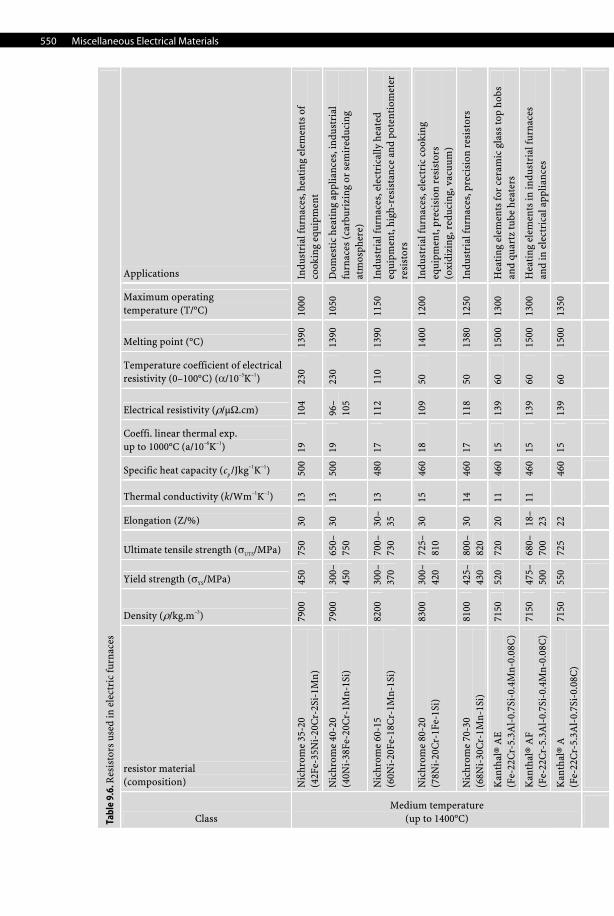
Tabl
e 9.
6. R
esis
tors
use
d in
ele
ctri
c fu
rnac
es
Class
resistor material (composition)
Density (ρ/kg.m–3)
Yield strength (σYS/MPa)
Ultimate tensile strength (σUTS/MPa)
Elongation (Z/%)
Thermal conductivity (k/Wm–1K–1)
Specific heat capacity (cp /Jkg–1K–1)
Coeffi. linear thermal exp. up to 1000°C (a/10–6K–1)
Electrical resistivity (ρ/μΩ.cm)
Temperature coefficient of electrical resistivity (0–100°C) (α/10–5K–1)
Melting point (°C)
Maximum operating temperature (T/°C)
Applications
Nic
hrom
e 35
-20
(42F
e-35
Ni-
20C
r-2S
i-1M
n)
7900
45
0 75
0 30
13
50
019
10
4 23
0 13
90
1000
In
dust
rial
furn
aces
, hea
ting
ele
men
ts o
f co
okin
g eq
uipm
ent
Nic
hrom
e 40
-20
(40N
i-38
Fe-2
0Cr-
1Mn-
1Si)
79
00
300–
450
650–
750
30
13
500
19
96–
105
230
1390
10
50
Dom
esti
c he
atin
g ap
plia
nces
, ind
ustr
ial
furn
aces
(ca
rbur
izin
g or
sem
ired
ucin
g
atm
osph
ere)
Nic
hrom
e 60
-15
(60N
i-20
Fe-1
8Cr-
1Mn-
1Si)
82
00
300–
370
700–
730
30–
35
13
480
17
112
110
1390
11
50
Indu
stri
al fu
rnac
es, e
lect
rica
lly h
eate
d
equi
pmen
t, hi
gh-r
esis
tanc
e an
d po
tent
iom
eter
re
sist
ors
Nic
hrom
e 80
-20
(78N
i-20
Cr-
1Fe-
1Si)
83
00
300–
420
725–
810
30
15
460
18
109
50
1400
12
00
Indu
stri
al fu
rnac
es, e
lect
ric
cook
ing
eq
uipm
ent,
prec
isio
n re
sist
ors
(o
xidi
zing
, red
ucin
g, v
acuu
m)
Nic
hrom
e 70
-30
(68N
i-30
Cr-
1Mn-
1Si)
81
00
425–
430
800–
820
30
14
460
17
118
50
1380
12
50
Indu
stri
al fu
rnac
es, p
reci
sion
res
isto
rs
Kan
thal
® A
E
(Fe-
22C
r-5.
3Al-
0.7S
i-0.
4Mn-
0.08
C)
7150
52
0 72
0 20
11
46
015
13
9 60
15
00
1300
H
eati
ng e
lem
ents
for
cera
mic
gla
ss to
p ho
bs
and
quar
tz tu
be h
eate
rs
Kan
thal
® A
F (F
e-22
Cr-
5.3A
l-0.
7Si-
0.4M
n-0.
08C
) 71
50
475–
500
680–
700
18–
23
11
460
15
139
60
1500
13
00
Hea
ting
ele
men
ts in
indu
stri
al fu
rnac
es
and
in e
lect
rica
l app
lianc
es
Medium temperature (up to 1400°C)
Kan
thal
® A
(F
e-22
Cr-
5.3A
l-0.
7Si-
0.08
C)
7150
55
0 72
5 22
460
15
139
60
1500
13
50
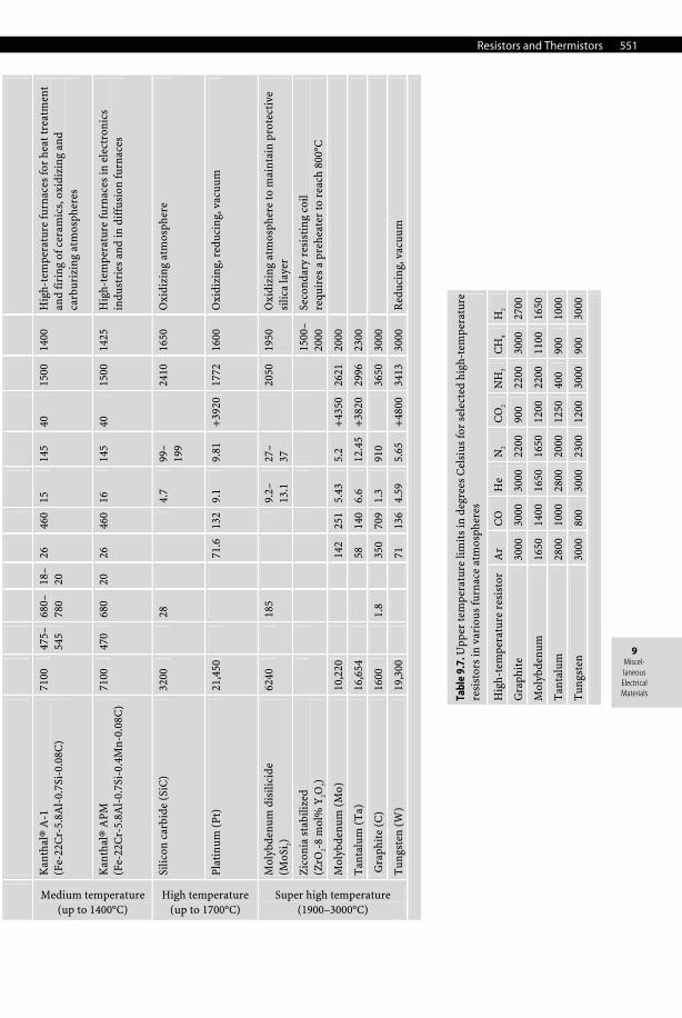
Resistors and Thermistors 551
9 Miscel-laneous
Electrical Materials
Kan
thal
® A
-1
(Fe-
22C
r-5.
8Al-
0.7S
i-0.
08C
) 71
00
475–
545
680–
780
18–
20
26
460
15
145
40
1500
14
00
Hig
h-te
mpe
ratu
re fu
rnac
es fo
r he
at tr
eatm
ent
and
firi
ng o
f cer
amic
s, o
xidi
zing
and
ca
rbur
izin
g at
mos
pher
es
Medium temperature (up to 1400°C)
Kan
thal
® A
PM
(Fe-
22C
r-5.
8Al-
0.7S
i-0.
4Mn-
0.08
C)
7100
47
0 68
0 20
26
46
016
14
5 40
15
00
1425
H
igh-
tem
pera
ture
furn
aces
in e
lect
roni
cs
indu
stri
es a
nd in
dif
fusi
on fu
rnac
es
Silic
on c
arbi
de (
SiC
) 32
00
28
4.7
99–
199
24
10
1650
O
xidi
zing
atm
osph
ere
High temperature (up to 1700°C)
Plat
inum
(Pt
) 21
,450
71.6
132
9.1
9.81
+
3920
17
72
1600
O
xidi
zing
, red
ucin
g, v
acuu
m
Mol
ybde
num
dis
ilici
de
(MoS
i 2)
6240
185
9.
2–
13.1
27
– 37
2050
19
50
Oxi
dizi
ng a
tmos
pher
e to
mai
ntai
n pr
otec
tive
si
lica
laye
r
Zic
onia
sta
biliz
ed
(ZrO
2-8
mol
% Y
2O3)
15
00–
2000
Se
cond
ary
resi
stin
g co
il re
quir
es a
pre
heat
er to
rea
ch 8
00°C
Mol
ybde
num
(M
o)
10,2
20
14
2 25
15.
43
5.2
+43
50
2621
20
00
Tan
talu
m (
Ta)
16
,654
58
140
6.6
12.4
5+
3820
29
96
2300
Gra
phit
e (C
) 16
00
1.
8
350
709
1.3
910
36
50
3000
Super high temperature (1900–3000°C)
Tun
gste
n (W
) 19
,300
71
136
4.59
5.
65
+48
00
3413
30
00
Red
ucin
g, v
acuu
m
Tabl
e 9.
7. U
pper
tem
pera
ture
lim
its
in d
egre
es C
elsi
us fo
r se
lect
ed h
igh-
tem
pera
ture
re
sist
ors
in v
ario
us fu
rnac
e at
mos
pher
es
Hig
h-te
mpe
ratu
re r
esis
tor
Ar
CO
H
e N
2 C
O2
NH
3 C
H4
H2
Gra
phit
e 30
00
3000
30
00
2200
90
0 22
00
3000
27
00
Mol
ybde
num
16
50
1400
16
50
1650
12
00
2200
11
00
1650
Tan
talu
m
2800
10
00
2800
20
00
1250
40
0 90
0 10
00
Tun
gste
n 30
00
800
3000
23
00
1200
30
00
900
3000
552 Miscellaneous Electrical Materials
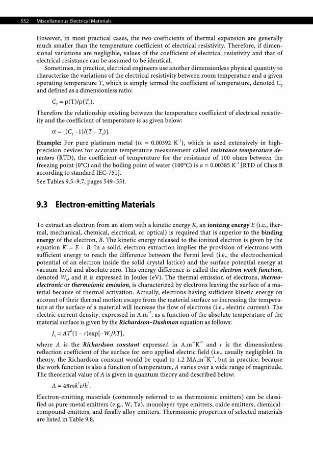
However, in most practical cases, the two coefficients of thermal expansion are generally much smaller than the temperature coefficient of electrical resistivity. Therefore, if dimen-sional variations are negligible, values of the coefficient of electrical resistivity and that of electrical resistance can be assumed to be identical.
Sometimes, in practice, electrical engineers use another dimensionless physical quantity to characterize the variations of the electrical resistivity between room temperature and a given operating temperature T, which is simply termed the coefficient of temperature, denoted CT and defined as a dimensionless ratio:
CT = ρ(T)/ρ(T0).
Therefore the relationship existing between the temperature coefficient of electrical resistiv-ity and the coefficient of temperature is as given below:
α = [(CT –1)/(T – T0)].
Example: For pure platinum metal (α = 0.00392 K–1), which is used extensively in high-precision devices for accurate temperature measurement called resistance temperature de-tectors (RTD), the coefficient of temperature for the resistance of 100 ohms between the freezing point (0°C) and the boiling point of water (100°C) is a = 0.00385 K–1 [RTD of Class B according to standard IEC-751]. See Tables 9.5–9.7, pages 549–551.
9.3 Electron-emitting Materials
To extract an electron from an atom with a kinetic energy K, an ionizing energy E (i.e., ther-mal, mechanical, chemical, electrical, or optical) is required that is superior to the binding energy of the electron, B. The kinetic energy released to the ionized electron is given by the equation K = E – B. In a solid, electron extraction implies the provision of electrons with sufficient energy to reach the difference between the Fermi level (i.e., the electrochemical potential of an electron inside the solid crystal lattice) and the surface potential energy at vacuum level and absolute zero. This energy difference is called the electron work function, denoted WS, and it is expressed in Joules (eV). The thermal emission of electrons, thermo-electronic or thermoionic emission, is characterized by electrons leaving the surface of a ma-terial because of thermal activation. Actually, electrons having sufficient kinetic energy on account of their thermal motion escape from the material surface so increasing the tempera-ture at the surface of a material will increase the flow of electrons (i.e., electric current). The electric current density, expressed in A.m–2, as a function of the absolute temperature of the material surface is given by the Richardson–Dushman equation as follows:
JS = AT2(1 – r)exp[–WS/kT],
where A is the Richardson constant expressed in A.m–2K–2 and r is the dimensionless reflection coefficient of the surface for zero applied electric field (i.e., usually negligible). In theory, the Richardson constant would be equal to 1.2 MA.m–2K–2, but in practice, because the work function is also a function of temperature, A varies over a wide range of magnitude. The theoretical value of A is given in quantum theory and described below:
A = 4πmk2e/h3.
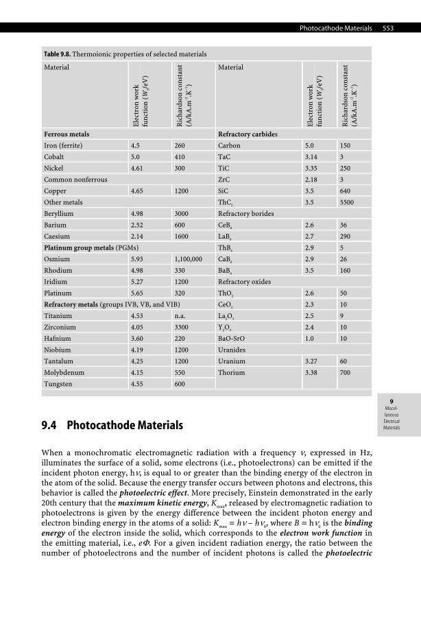
Electron-emitting materials (commonly referred to as thermoionic emitters) can be classi-fied as pure-metal emitters (e.g., W, Ta), monolayer-type emitters, oxide emitters, chemical-compound emitters, and finally alloy emitters. Thermoionic properties of selected materials are listed in Table 9.8.
Photocathode Materials 553
9 Miscel-laneous
Electrical Materials
Table 9.8. Thermoionic properties of selected materials
Material
Ele
ctro
n w
ork
func
tion
(W
S/eV
)
Ric
hard
son
cons
tant
(A
/kA
.m–2
.K–1
)
Material
Ele
ctro
n w
ork
func
tion
(W
S/eV
)
Ric
hard
son
cons
tant
(A
/kA
.m–2
.K–1
)
Ferrous metals Refractory carbides
Iron (ferrite) 4.5 260 Carbon 5.0 150
Cobalt 5.0 410 TaC 3.14 3
Nickel 4.61 300 TiC 3.35 250
Common nonferrous ZrC 2.18 3
Copper 4.65 1200 SiC 3.5 640
Other metals ThC2 3.5 5500
Beryllium 4.98 3000 Refractory borides
Barium 2.52 600 CeB6 2.6 36
Caesium 2.14 1600 LaB6 2.7 290
Platinum group metals (PGMs) ThB6 2.9 5
Osmium 5.93 1,100,000 CaB6 2.9 26
Rhodium 4.98 330 BaB6 3.5 160
Iridium 5.27 1200 Refractory oxides
Platinum 5.65 320 ThO2 2.6 50
Refractory metals (groups IVB, VB, and VIB) CeO2 2.3 10
Titanium 4.53 n.a. La2O3 2.5 9
Zirconium 4.05 3300 Y2O3 2.4 10
Hafnium 3.60 220 BaO-SrO 1.0 10
Niobium 4.19 1200 Uranides
Tantalum 4.25 1200 Uranium 3.27 60
Molybdenum 4.15 550
Tungsten 4.55 600
Thorium 3.38 700
9.4 Photocathode Materials
When a monochromatic electromagnetic radiation with a frequency ν, expressed in Hz, illuminates the surface of a solid, some electrons (i.e., photoelectrons) can be emitted if the incident photon energy, hν, is equal to or greater than the binding energy of the electron in the atom of the solid. Because the energy transfer occurs between photons and electrons, this behavior is called the photoelectric effect. More precisely, Einstein demonstrated in the early 20th century that the maximum kinetic energy, Kmax, released by electromagnetic radiation to photoelectrons is given by the energy difference between the incident photon energy and electron binding energy in the atoms of a solid: Kmax = hν – hν0, where B = hν0 is the binding energy of the electron inside the solid, which corresponds to the electron work function in the emitting material, i.e., eΦ. For a given incident radiation energy, the ratio between the number of photoelectrons and the number of incident photons is called the photoelectric
554 Miscellaneous Electrical Materials
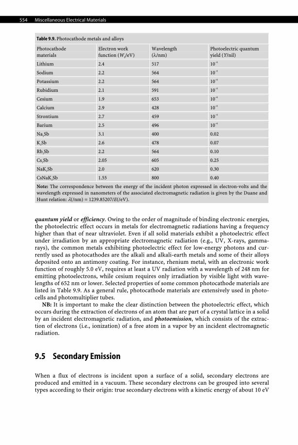
Table 9.9. Photocathode metals and alloys
Photocathode materials
Electron work function (WS/eV)
Wavelength (λ/nm)
Photoelectric quantum yield (Y/nil)
Lithium 2.4 517 10–4
Sodium 2.2 564 10–4
Potassium 2.2 564 10–4
Rubidium 2.1 591 10–4
Cesium 1.9 653 10–4
Calcium 2.9 428 10–4
Strontium 2.7 459 10–4
Barium 2.5 496 10–4
Na3Sb 3.1 400 0.02
K3Sb 2.6 478 0.07
Rb3Sb 2.2 564 0.10
Cs3Sb 2.05 605 0.25
NaK3Sb 2.0 620 0.30
CsNaK3Sb 1.55 800 0.40
Note: The correspondence between the energy of the incident photon expressed in electron-volts and the wavelength expressed in nanometers of the associated electromagnetic radiation is given by the Duane and Hunt relation: λ(/nm) = 1239.85207/E(/eV).
quantum yield or efficiency. Owing to the order of magnitude of binding electronic energies, the photoelectric effect occurs in metals for electromagnetic radiations having a frequency higher than that of near ultraviolet. Even if all solid materials exhibit a photoelectric effect under irradiation by an appropriate electromagnetic radiation (e.g., UV, X-rays, gamma-rays), the common metals exhibiting photoelectric effect for low-energy photons and cur-rently used as photocathodes are the alkali and alkali-earth metals and some of their alloys deposited onto an antimony coating. For instance, rhenium metal, with an electronic work function of roughly 5.0 eV, requires at least a UV radiation with a wavelength of 248 nm for emitting photoelectrons, while cesium requires only irradiation by visible light with wave-lengths of 652 nm or lower. Selected properties of some common photocathode materials are listed in Table 9.9. As a general rule, photocathode materials are extensively used in photo-cells and photomultiplier tubes.
NB: It is important to make the clear distinction between the photoelectric effect, which occurs during the extraction of electrons of an atom that are part of a crystal lattice in a solid by an incident electromagnetic radiation, and photoemission, which consists of the extrac-tion of electrons (i.e., ionization) of a free atom in a vapor by an incident electromagnetic radiation.
9.5 Secondary Emission
When a flux of electrons is incident upon a surface of a solid, secondary electrons are produced and emitted in a vacuum. These secondary electrons can be grouped into several types according to their origin: true secondary electrons with a kinetic energy of about 10 eV
Electrolytes 555
9 Miscel-laneous
Electrical Materials
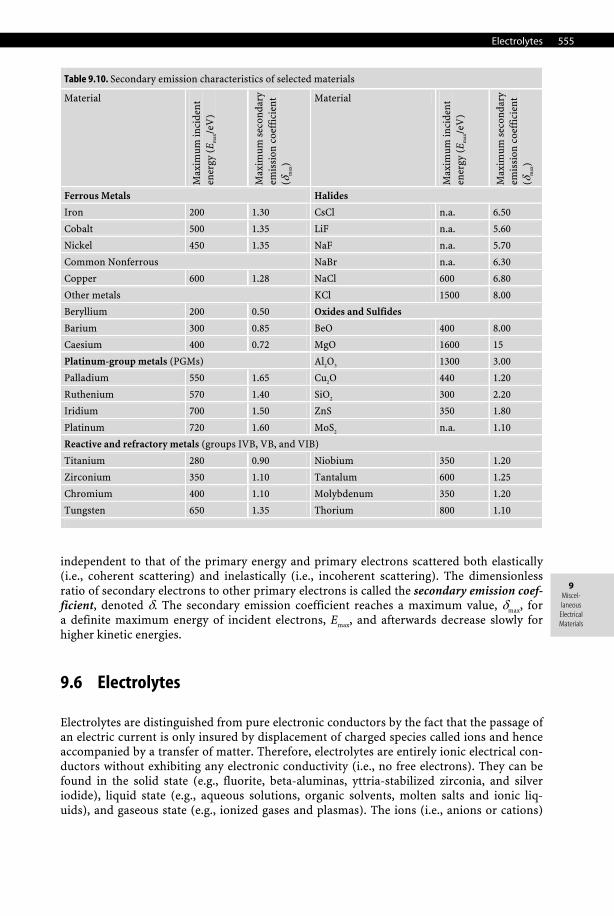
Table 9.10. Secondary emission characteristics of selected materials
Material
Max
imum
inci
den
t en
ergy
(E m
ax/e
V)
Max
imum
sec
onda
ry
emis
sion
coe
ffic
ient
(δ
max
)
Material
Max
imum
inci
den
t en
ergy
(E m
ax/e
V)
Max
imum
sec
onda
ry
emis
sion
coe
ffic
ient
(δ
max
)
Ferrous Metals Halides
Iron 200 1.30 CsCl n.a. 6.50
Cobalt 500 1.35 LiF n.a. 5.60
Nickel 450 1.35 NaF n.a. 5.70
Common Nonferrous NaBr n.a. 6.30
Copper 600 1.28 NaCl 600 6.80
Other metals KCl 1500 8.00
Beryllium 200 0.50 Oxides and Sulfides
Barium 300 0.85 BeO 400 8.00
Caesium 400 0.72 MgO 1600 15
Platinum-group metals (PGMs) Al2O3 1300 3.00
Palladium 550 1.65 Cu2O 440 1.20
Ruthenium 570 1.40 SiO2 300 2.20
Iridium 700 1.50 ZnS 350 1.80
Platinum 720 1.60 MoS2 n.a. 1.10
Reactive and refractory metals (groups IVB, VB, and VIB)
Titanium 280 0.90 Niobium 350 1.20
Zirconium 350 1.10 Tantalum 600 1.25
Chromium 400 1.10 Molybdenum 350 1.20
Tungsten 650 1.35 Thorium 800 1.10
independent to that of the primary energy and primary electrons scattered both elastically (i.e., coherent scattering) and inelastically (i.e., incoherent scattering). The dimensionless ratio of secondary electrons to other primary electrons is called the secondary emission coef-ficient, denoted δ. The secondary emission coefficient reaches a maximum value, δmax, for a definite maximum energy of incident electrons, Emax, and afterwards decrease slowly for higher kinetic energies.
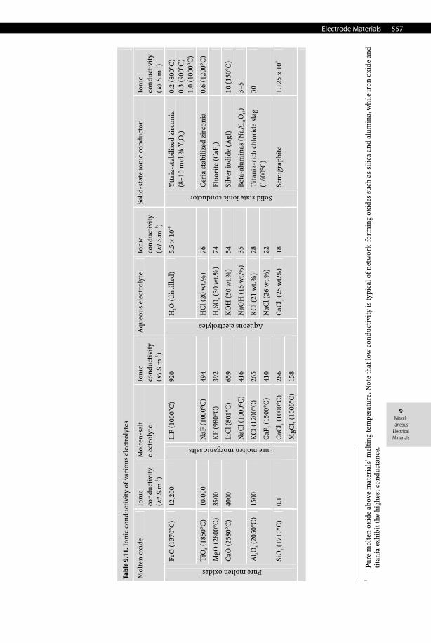
9.6 Electrolytes
Electrolytes are distinguished from pure electronic conductors by the fact that the passage of an electric current is only insured by displacement of charged species called ions and hence accompanied by a transfer of matter. Therefore, electrolytes are entirely ionic electrical con-ductors without exhibiting any electronic conductivity (i.e., no free electrons). They can be found in the solid state (e.g., fluorite, beta-aluminas, yttria-stabilized zirconia, and silver iodide), liquid state (e.g., aqueous solutions, organic solvents, molten salts and ionic liq-uids), and gaseous state (e.g., ionized gases and plasmas). The ions (i.e., anions or cations)
556 Miscellaneous Electrical Materials
ensure the proper ionic conductivity by moving under the electrical field imposed by the electrodes. Usually, electrolytes can be grouped into three main classes:
• Pure electrolytes. This class is entirely represented by molten or fused salts (e.g., molten cryolite, Na3AlF6) and usually requires high temperatures—largely above the melting or liquidus temperature of the salt—to provide sufficient ionic conductivity.
• Ionic solutions. This class is represented by electrolytic solutions and is also split into two subclasses according to ionic conductivity and dissociation constant. − Strong electrolytes (ionophores). Potassium chloride (KCl) is the main example of the
class of ionophores, that is, pure ionic compounds (solids, liquids, or gases) already made of anions and cations. The dissolution of these ionophores simply involves the dispersion of preexisting ions of the crystal lattice into an appropriate solvent followed by a reorganization of solvent molecules around ions (i.e., the solvation process). This phenomenon strongly depends on the relative electric permittivity εr (i.e., formerly the dielectric constant) of the solvent. Actually, in ionizing solvents—those, like water (εr = 78.36 at 298.15K), having a high electric permittivity—the coulombic interaction between ions is strongly decreased. Hence, ions maintain a certain independence in their displacement, and they are totally dissociated (i.e., ionized). By contrast, in inert solvents (e.g., benzene)—those exhibiting a low electric permittivity—ionic entities such as pairs or clusters form, losing their freedom. For instance, in a series of solvents of decreasing permittivity, ions form double, triple, and quadruple associations such as LiBF4 in dimethoxyethane (εr = 7.15 at 298.15K).
− Weak electrolytes. In this case the solute is only partially ionized (e.g., NH4Cl in water). Salts obtained by the neutralization of a weak acid by a strong base (e.g., CH3COO–Na+), a weak base by a strong acid (e.g., NH4Cl), or a weak acid by a weak base (e.g., CH3COO–NH4
+) are typical examples of weak electrolytes. • Solid electrolytes. These correspond to solid materials in which the ionic mobility is in-
sured by various intrinsic and extrinsic defects and are called solid ion conductors. Com-mon examples are ion-conducting solids with rock salt or halite-type solids with a B1 structure (e.g., α-AgI), oxygen-conducting solids with a fluorite-type C1 structure (AIIO2), for instance CaF2 and yttria-stabilized zirconia (YSZ, ZrO2 with 8 mol.% Y2O3), a pyro-chlore structure (A2B2O7), perovskite-type oxides (AIIBIVO3), La2Mo2O9, or solids with the spinel-type structure such as beta-aluminas (NaAl11O17) for which the ionic conduction is ensured by Na+ mobility.
See Table 9.11.
9.7 Electrode Materials
9.7.1 Electrode Materials for Batteries and Fuel Cells
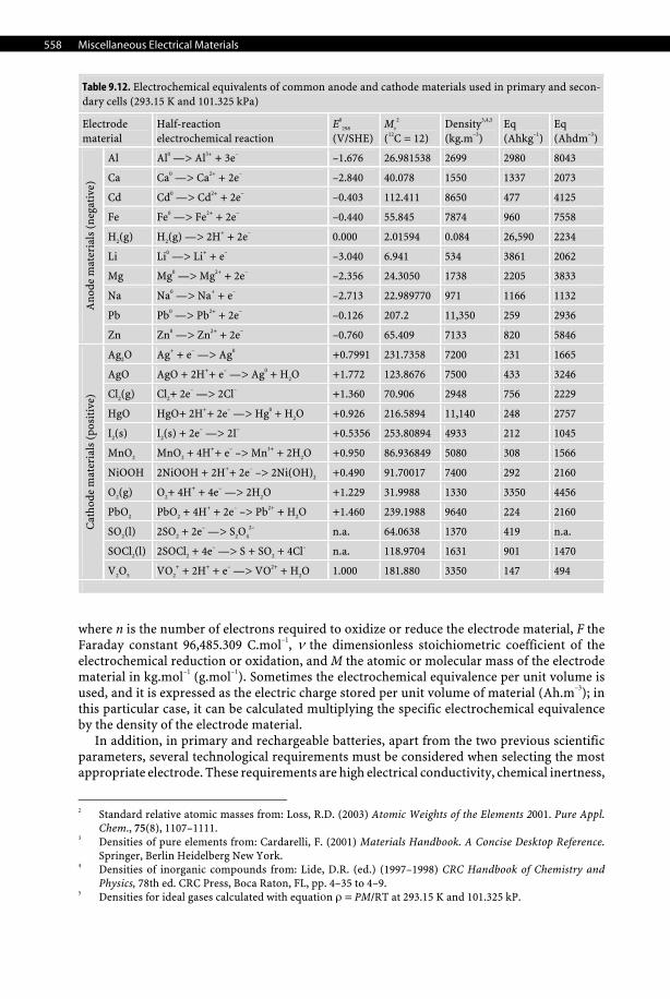
In power sources, i.e., primary and secondary batteries, and fuel cells, the electrode material of both cathode and anode must exhibit a high standard electrode potential expressed in volts (V). Actually, an anode material must be highly electropositive, i.e., reducing, while a cathode material must be highly electronegative, i.e., oxidizing. The second important physical quantity required to select the most appropriate electrode material is its electro-chemical equivalence. The electrochemical equivalence, denoted Eq, of an electrode material expresses the available electric charge stored per unit mass of material, and hence it is ex-pressed in C.kg–1 (Ah.g–1) and calculated with the following equation:
Eq = n·F/v·M,
Electrode Materials 557
9 Miscel-laneous
Electrical Materials
1
Pure
mol
ten
oxid
e ab
ove
mat
eria
ls’ m
elti
ng te
mpe
ratu
re. N
ote
that
low
con
duct
ivit
y is
typi
cal o
f net
wor
k-fo
rmin
g ox
ides
suc
h as
sili
ca a
nd a
lum
ina,
whi
le ir
on o
xide
and
ti
tani
a ex
hibi
t the
hig
hest
con
duct
ance
.
Tabl
e 9.
11. I
onic
con
duct
ivit
y of
var
ious
ele
ctro
lyte
s
Mol
ten
oxid
e Io
nic
co
nduc
tivi
ty
(κ /
S.m
–1)
Mol
ten-
salt
el
ectr
olyt
e Io
nic
co
nduc
tivi
ty(κ
/ S.
m–1
)
Aqu
eous
ele
ctro
lyte
Io
nic
co
nduc
tivi
ty
(κ /
S.m
–1)
Solid
-sta
te io
nic
cond
ucto
r Io
nic
co
nduc
tivi
ty(κ
/ S.
m–1
)
FeO
(13
70°C
) 12
,200
Li
F (1
000°
C)
920
H2O
(di
still
ed)
5.5
× 10
–6
Ytt
ria-
stab
ilize
d zi
rcon
ia
(8–1
0 m
ol.%
Y2O
3)
0.2
(800
°C)
0.3
(900
°C)
1.0
(100
0°C
)
TiO
2 (18
50°C
) 10
,000
N
aF (
1000
°C)
494
HC
l (20
wt.%
) 76
C
eria
sta
biliz
ed z
irco
nia
0.6
(120
0°C
)
MgO
(28
00°C
) 35
00
KF
(980
°C)
392
H2S
O4 (
30 w
t.%)
74
Fluo
rite
(C
aF2)
LiC
l (80
1°C
) 65
9 K
OH
(30
wt.%
) 54
Si
lver
iodi
de (
AgI
) 10
(15
0°C
) C
aO (
2580
°C)
4000
NaC
l (10
00°C
) 41
6 N
aOH
(15
wt.
%)
35
Bet
a-al
umin
as (
NaA
l 11O
17)
3–5
KC
l (12
00°C
) 26
5 K
Cl (
21 w
t.%)
28
Al 2O
3 (20
50°C
) 15
00
CaF
2 (15
00°C
) 41
0 N
aCl (
26 w
t.%
) 22
Tit
ania
-ric
h ch
lori
de s
lag
(1
600°
C)
30
CaC
l 2 (10
00°C
) 26
6
Pure molten oxides1
SiO
2 (17
10°C
) 0.
1
Pure molten inorganic salts
MgC
l 2 (10
00°C
) 15
8
Aqueous electrolytes
CaC
l 2 (25
wt.%
) 18
Solid state ionic conductor
Sem
igra
phit
e 1.
125
x 10
5
558 Miscellaneous Electrical Materials
Table 9.12. Electrochemical equivalents of common anode and cathode materials used in primary and secon-dary cells (293.15 K and 101.325 kPa)
Electrode material
Half-reaction electrochemical reaction
E0
298
(V/SHE) Mr
2
(12C = 12) Density3,4,5
(kg.m–3) Eq (Ahkg–1)
Eq (Ahdm–3)
Al Al0 —> Al3+ + 3e– –1.676 26.981538 2699 2980 8043
Ca Ca0 —> Ca2+ + 2e– –2.840 40.078 1550 1337 2073
Cd Cd0 —> Cd2+ + 2e– –0.403 112.411 8650 477 4125
Fe Fe0 —> Fe2+ + 2e– –0.440 55.845 7874 960 7558
H2(g) H2(g) —> 2H+ + 2e– 0.000 2.01594 0.084 26,590 2234
Li Li0 —> Li+ + e– –3.040 6.941 534 3861 2062
Mg Mg0 —> Mg2+ + 2e– –2.356 24.3050 1738 2205 3833
Na Na0 —> Na+ + e– –2.713 22.989770 971 1166 1132
Pb Pb0 —> Pb2+ + 2e– –0.126 207.2 11,350 259 2936
Ano
de m
ater
ials
(ne
gati
ve)
Zn Zn0 —> Zn2+ + 2e– –0.760 65.409 7133 820 5846
Ag2O Ag+ + e– —> Ag0 +0.7991 231.7358 7200 231 1665
AgO AgO + 2H++ e– —> Ag0 + H2O +1.772 123.8676 7500 433 3246
Cl2(g) Cl2+ 2e– —> 2Cl– +1.360 70.906 2948 756 2229
HgO HgO+ 2H++ 2e– —> Hg0 + H2O +0.926 216.5894 11,140 248 2757
I2(s) I2(s) + 2e– —> 2I– +0.5356 253.80894 4933 212 1045
MnO2 MnO2 + 4H++ e– –> Mn3+ + 2H2O +0.950 86.936849 5080 308 1566
NiOOH 2NiOOH + 2H++ 2e– –> 2Ni(OH)2 +0.490 91.70017 7400 292 2160
O2(g) O2+ 4H+ + 4e– —> 2H2O +1.229 31.9988 1330 3350 4456
PbO2 PbO2 + 4H+ + 2e– –> Pb2+ + H2O +1.460 239.1988 9640 224 2160
SO2(l) 2SO2 + 2e– —> S2O4
2– n.a. 64.0638 1370 419 n.a.
SOCl2(l) 2SOCl2 + 4e– —> S + SO2 + 4Cl– n.a. 118.9704 1631 901 1470
Cat
hode
mat
eria
ls (
posi
tive
)
V2O5 VO2
+ + 2H+ + e– —> VO2+ + H2O 1.000 181.880 3350 147 494
where n is the number of electrons required to oxidize or reduce the electrode material, F the Faraday constant 96,485.309 C.mol–1, ν the dimensionless stoichiometric coefficient of the electrochemical reduction or oxidation, and M the atomic or molecular mass of the electrode material in kg.mol–1 (g.mol–1). Sometimes the electrochemical equivalence per unit volume is used, and it is expressed as the electric charge stored per unit volume of material (Ah.m–3); in this particular case, it can be calculated multiplying the specific electrochemical equivalence by the density of the electrode material.
In addition, in primary and rechargeable batteries, apart from the two previous scientific parameters, several technological requirements must be considered when selecting the most appropriate electrode. These requirements are high electrical conductivity, chemical inertness,
2 Standard relative atomic masses from: Loss, R.D. (2003) Atomic Weights of the Elements 2001. Pure Appl.
Chem., 75(8), 1107–1111. 3 Densities of pure elements from: Cardarelli, F. (2001) Materials Handbook. A Concise Desktop Reference.
Springer, Berlin Heidelberg New York. 4 Densities of inorganic compounds from: Lide, D.R. (ed.) (1997–1998) CRC Handbook of Chemistry and
Physics, 78th ed. CRC Press, Boca Raton, FL, pp. 4–35 to 4–9. 5 Densities for ideal gases calculated with equatiοn ρ = PM/RT at 293.15 K and 101.325 kP.
Electrode Materials 559
9 Miscel-laneous
Electrical Materials
ease of fabrication, involvement of nonstrategic materials, low cost, and finally commercial availability. As a general rule, metals and alloys represent the major anode materials in batter-ies, except for the particular case of hydrogen in fuel cells, while metallic oxides, hydroxides, chlorides, and sulfides represent the major anodic materials, except oxygen, in fuel cells.
9.7.2 Intercalation Compounds
Insertion, also called intercalation, is a topotactic reaction that consists of the insertion of a species, atom, or molecule inside the interstitial crystal lattice of a solid host material, with or without charge transfer. Historically, the first intercalation compounds were the graphites (1841) for which the intercalation of cations of alkali metals occurred between the graphene lamellar planes and the hydrogen/palladium system (1866). Later, in 1959, the phenomenon was recorded in lamellar dichalcogenides and since the 1970s hundreds of new compounds have been reported, several of them now being used in rechargeable batteries such as Ni-MH or lithium batteries.
In the particular case of lithiation or delithiation of cathode materials used in lithium sec-ondary batteries, the calculation of the electrochemical equivalent involves an additional parameter related to the reaction of intercalation of lithium cations into the crystal lattice of the host cathode materials. Consider the theoretical reversible reaction of intercalation of lithium into a crystal lattice of a solid host material (e.g., oxide, sulfide):
xLi+ + yM + xe– <—> LixMy
with Li+ lithium cations, M solid host cathode material, x,y dimensionless stoichiometric coefficients, x dimensionless number of electrons exchanged.
Hence during the lithiation reaction (i.e., charge), x moles of lithium cations are reduced and intercalated into y moles of the solid host material, and a quantity of electricity, xF, must be supplied to the cell. Conversely, during delithiation (i.e., discharge), x moles of lithium cations are produced and a quantity of electricity, xF, is supplied to the external circuit of the cell. Therefore, the quantity of electricity, Q, expressed in coulombs (Ah), delivered following the deintercalation of lithium from a mass, mM, of the solid host material or a mass, mLixMy, of the final intercalated compound is given by the two following relations:
Q = mM . (xF/yMM) = mLixMy . (xF/MLixMy),
with mM mass of the solid host material, in kg, mLixMy mass of the intercalated compound, in kg, x, y dimensionless stoichiometric coefficients, MM molar mass of the solid host materials, in kg.mol–1, MLixMy molar mass of the intercalated compounds, in kg.mol–1, x dimensionless number of electrons exchanged, F Faraday constant F = 96,485.309 C.mol–1.
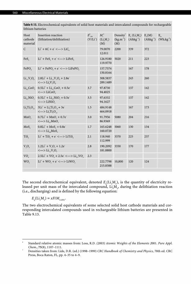
From the above equation it is possible to define two types of electrochemical equivalents. The first electrochemical equivalent, denoted Eq(M), is the quantity of electricity consumed per unit mass of the solid host material, M, during the lithiation reaction (i.e., charging) and is defined by the following equation:
Eq(M) = xF/yMM.
560 Miscellaneous Electrical Materials
Table 9.13. Electrochemical equivalents of solid host materials and intercalated compounds for rechargeable lithium batteries
Host cathode material
Insertion reaction (lithiation/delithiation)
E0
298
(V/Li+)Mr
6
(LixMy) (M)
Density7
(kg.m–3)(M)
Eq (LixMy)(Ahkg–1)
Eq(M) (Ahkg–1)
Em
(Wh.kg–3)
C Li+ + 6C + e– <—> LiC6 79.0070 12.011
2200 339 372
FeS2 Li+ + FeS2 + e– <—> LiFeS2 126.9180119.9770
5020 211 223
FePO4 Li+ + FePO4 + e– <—> LiFePO4 157.7574150.8164
167 178
Li1.2V3O8 2.8Li+ + Li1.2V3O8 + 2.8e– <—> Li4V3O8
308.5837289.1489
243 260
Li0.5CoO2 0.5Li+ + Li0.5CoO2 + 0.5e– <—> LiCoO2
3.7 97.8730 94.4025
137 142
Li0.5NiO2 0.5Li+ + Li0.5NiO2 + 0.5e– <—> LiNiO2
3.5 97.6332 94.1627
137 142
Li4Ti5O12 3Li+ + Li4Ti5O12 + 3e– <—> Li7Ti5O12
1.5 484.9148464.0918
167 173
MnO2 0.7Li+ + MnO2 + 0.7e–
<—> Li0.7MnO2 3.0 91.7956
86.9369 5080 204 216
MoS2 0.8Li+ + MoS2 + 0.8e– <—> Li0.8MoS2
1.7 165.6248160.0720
5060 130 134
TiS2 Li+ + TiS2 + e– <—> LiTiS2 2.1 118.940 112.999
3370 225 237
V2O5 1.2Li+ + V2O5 + 1.2e– <—> Li1.2V2O5
2.8 190.2092181.8800
3350 170 177
VOx 2.5Li+ + VOx + 2.5e– <—> Li2.5VOx 2.3
WO2 Li+ + WO2 + e– <—> LiWO2 222.7798215.8388
10,800 120 124
The second electrochemical equivalent, denoted Eq(LixMy), is the quantity of electricity re-leased per unit mass of the intercalated compound, LixMy, during the delithiation reaction (i.e., discharging) and is defined by the following equation:
Eq(LixMy) = xF/MLixMy.
The two electrochemical equivalents of some selected solid host cathode materials and cor-responding intercalated compounds used in rechargeable lithium batteries are presented in Table 9.13.
6 Standard relative atomic masses from: Loss, R.D. (2003) Atomic Weights of the Elements 2001. Pure Appl.
Chem., 75(8), 1107–1111. 7 Densities taken from: Lide, D.R. (ed.) (1998–1999) CRC Handbook of Chemistry and Physics, 78th ed. CRC
Press, Boca Raton, FL, pp. 4–35 to 4–9.
Electrode Materials 561
9 Miscel-laneous
Electrical Materials
9.7.3 Electrode Materials for Electrolytic Cells
Today, in modern the chemical process industry, electrochemistry occupies an important place. Electrochemical processes are actually widely used in the inorganic syntheses.8 Actu-ally, it is the only method for preparing and recovering several pure elements (e.g., alumi-num, magnesium, alkali and alkali-earth metals, chlorine, and fluorine).9 Furthermore, it occupies an important place in hydrometallurgy for electrowinning and electrorefining metals of groups IB (e.g., Cu, Ag, Au), IIB (e.g., Zn, Cd), and IVA (e.g., Sn, Pb).10,11 In addi-tion, its development also concerns organic synthesis, where some processes reach industrial scale (e.g., Monsanto, Nalco, and Philips processes).12 Apart from electrochemical processes for preparing inorganic and organic compounds, other electrolytic processes are also used in various fields: in extractive hydrometallurgy (e.g., the electrolytic recovery of zinc13), in zinc electroplating (e.g., high-speed electrogalvanizing of steel plates14), in electrodialysis (e.g., the salt-splitting regeneration of sulfuric acid and sodium hydroxide from sodium sulfate waste brines,15,16 the regeneration of the leaching solutions of uranium ores, the electrolytic regeneration of spent pickling solutions17), and finally in processes for a cleaner environ-ment, where electrochemistry is used to achieve the electrooxidation of organic pollutants (i.e., electrolytic mineralization or electroincineration), and in the removal of hazardous metal cations from liquid wastes effluents.18
Electrochemical processes are performed in an electrolytic cell19 (i.e., electrolyser). The electrolyzer is a reactor vessel, filled with an electrolytic bath or electrolyte, in which the elec-trodes are immersed and electrically connected via busbars to a power supply. When the electrolyzer is split into two compartments by a separator (e.g., diaphragm, membrane), the electrolyte has two different compositions (i.e., anolyte and catholyte). The electrodes are the main parts of an electrolyzer and consist of the anode (i.e., positive, +) where the oxidation reaction occurs, while at the cathode (i.e., negative, –) a reduction takes place. Among the several issues encountered by engineers for designing an industrial electrochemical reactor, one of them consists in reducing the specific electric energy consumption (i.e., electric energy per unit mass of product). The specific energy consumption can be minimized in two ways: increasing the current efficiency and lowering the operating cell voltage. Other issues for designing electrochemical cells are discussed in more detail elsewhere in the literature.20,21,22 8 Srinivasan, V.; Lipp, L. (2003) Report on the electrolytic industries for the year 2002. J. Electrochem. Soc.,
150(12), K15–38. 9 Pletcher, D.; Walsh, F.C. (1990) Industrial Electrochemistry, 2nd ed. Chapman & Hall, London. 10 Kuhn, A.T. (1977) Electrochemistry of Lead. Academic, London. 11 Gonzalez-Dominguez, J.A.; Peters, E.; Dreisinger, D.B. (1991) The refining of lead by the Betts process. J.
Appl. Electrochem., 21(3), 189–202. 12 Baizer, M.M.; Lund, H. (1983) Organic Electrochemistry: An Introduction and a Guide, 2nd ed. Marcel
Dekker, New York. 13 Karavasteva, M.; Karaivanov, St. (1993) Electrowinning of zinc at high current density in the presence of
some surfactants. J. Appl. Electrochem., 23(7), 763–765. 14 Hardee, K.L.; Mitchell, L.K.; Rudd, E.D. (1989) Plat. Surf. Finish., 76(4), 68. 15 Thompson, J.; Genders, D. (1992) Process for producing sodium hydroxide and ammonium sulfate from
sodium sulfate. US Patent 5,098,532; March 24, 1992. 16 Pletcher, D.; Genders, J.D.; Weinberg, N.L.; Spiegel, E.F. (1993) Electrochemical methods for production
of alkali metal hydroxides without the co-production of chlorine. US Patent 5,246,551; September 21, 1993.
17 Schneider, L. (1995) Process and apparatus for regenerating an aqueous solution containing metal ions and sulfuric acid. US Patent 5,478,448; December 26, 1995.
18 Genders, D.; Weinberg, N.L. (eds.) (1992) Electrochemistry for a Cleaner Environment. Electrosynthesis Co., Lancaster, NY.
19 Wendt, S.; Kreysa, G. (1999) Electrochemical Engineering. Springer, Berlin Heidelberg New York. 20 Pickett, D.J. (1979) Electrochemical Reactor Design. Elsevier, Amsterdam. 21 Rousar, I.; Micka, K.; Kimla, A. (1985) Electrochemical Engineering, Vols. 1 and 2. Elsevier, Amsterdam.
562 Miscellaneous Electrical Materials
The overall cell voltage at a given current density, Ucell, can be classically described as the following algebraic sum:
ΔUcell = ∑k(Ea,th – Ec,th) + ∑k(ηa,k – ηc,k) + i∑kRk + ΔUt = ΔUth + Δη + iRtot+ ΔUt,
where the first term corresponds to the Nernstian theoretical or thermodynamic cell voltage and consists of the algebraic difference between the thermodynamic potentials of the anode and cathode respectively (i.e., Nernst electrode potentials), the second term is the summation of all the electrode overpotentials (e.g., activation, concentration, passivation, etc.), the third term is the summation of all the ohmic drops (e.g., electrolytes, both anolyte and catholyte, separators, connectors, and busbars), and finally cell potential drift is due to the aging of electrodes (e.g., corrosion, deactivation, and passivation) and/or separator materials (e.g., fooling, degradation, and swelling).
Hence, the operating cell voltage could be reduced In several ways.23 First, an appropriate counter electrode reaction minimizes the reversible cell voltage. Second, a narrow interelec-trode gap and electrode-membrane gap in association with a highly conductive electrolyte and separator and highly conductive metals for busbars, feeders, and connectors diminish the overall ohmic drop. Third, turbulent promoters should be used to enhance convection and hence the mass transfer coefficient in order to reduce the concentration overpotential. Finally, the activation overpotential could be reduced by using an efficient and appropriate electrocatalyst. The selection of a catalyst is an important problem to solve, particularly in the case of oxygen or chlorine anodes. For theoretical aspects of electrocatalysis, they are reviewed extensively in more detail by Trasatti.24 Indeed, because of the complex behavior of electrodes, the selection of an electrocatalyst for a given process cannot be made simply on the basis of electrochemical kinetic considerations (i.e., exchange current density, Tafel slopes). An experimental approach is compulsory. Actually, the prediction of an electrode’s service life requires real standardized tests (i.e., accelerated service-life tests). For the prac-ticing engineer, several scientific and technical criteria must be considered when selecting an appropriate electrode material. Therefore, electrode materials must exhibit the following requirements:
(i) high exchange current density (jo) and a good electron transfer coefficient (α or β ) for the selected electrochemical reaction to decrease activation overpotential;
(ii) good electronic conductivity to decrease the ohmic drop and the Joule’s heating; (iii) good corrosion resistance to both chemical and electrochemical reactions, combined
with no passivating and blistering behavior, leading to abnormal electrode degradation and consumption;
(iv) a good set of mechanical properties suited for industrial use (i.e., low density, high tensile strength, stiffness);
(v) ease of fabrication (i.e., machining, joining, and cleaning) allowing one to obtain clean and intricate shapes;
(vi) low cost combined with commercial availability and a wide variety of products (e.g., rod, sheet, expanded metal);
(vii) nonhazardous, nontoxic, and environmentally friendly material.
It is important to note that the combination of criteria (3) and (4) is essential for the di-mensional stability of an electrode and its service life.
22 Hine, F. (1985) Electrode Processes and Electrochemical Engineering. Plenum, New York. 23 Couper, A.M.; Pletcher, D.; Walsh, F.C. (1990) Electrode materials for electrosynthesis. Chem. Rev., 90(5),
837−865. 24 Trasatti, S. In: Lipkowski, J.; Ross, P.N. (eds.) (1994) The Electrochemistry of Novel Materials. VCH, New
York, Chap. 5, pp. 207–295.
Electrode Materials 563
9 Miscel-laneous
Electrical Materials
9.7.3.1 Industrial Cathode Materials Generally speaking, the selection of a cathode material is easier for the electrochemist or the electrochemical engineer than selecting an anode material. Actually, given that the most important factor in selecting a cathode material is the overpotential for the evolution of hydrogen, there exists a wide range of electronically conductive materials with the desired overpotential for both acid and alkaline electrolytes. For instance, some metals exhibit a high overpotential (e.g., Cd, Pb, Hg), while other materials are characterized by a low overpoten-tial (e.g, Pt, Cu, Ag, platinized C, and Ni). The second most important factor is the stability of the cathode material toward nascent hydrogen gas evolved during the cathodic polariza-tion of the material. Several refractory metals used as cathodes (e.g., Ti, Nb, Ta, Fe, and steels) are prone to hydrogen pickup and hence are extremely sensitive to hydrogen embrit-tlement, which leads to the blistering or even spalling of the metal affecting its dimensional stability. Therefore, these metals are not suited for the type of manufacturing cathodes that must be used in aqueous electrolytes.
9.7.3.1.1 Low-Carbon Steel Cathodes Low-carbon steel exhibits a low hydrogen overpotential and a low cost and can be obtained in a wide variety of mill products. In addition, with its ease of fabrication, joining, and clean-ing, it is the standard cathode material in the chlor-alkali industry in either the membrane or diaphragm processes. If cathodically polarized during shutdowns and carefully handled, it offers an unlimited service life. When the hydrogen overpotential must be decreased, Ni- and Co-based coatings can be applied onto it by electrochemical or thermal decomposition techniques. Sometimes a Ni-Zn or Ni-Al coating is deposited and the Zn or Al is later re-moved by an alkaline hot leach with 50 wt.% NaOH, leaving a Raney nickel catalyst, greatly enhancing the active surface area. Recently, noble-metal coatings, combined with the intro-duction of a catalyst into the electrolyte, have also been reported in the literature.
9.7.3.1.2 Aluminum Cathodes Aluminum metal and, to a lesser extent, aluminum alloys are suitable materials for manufac-turing industrial cathodes. Actually, pure aluminum metal exhibits a low density (2690 kg.m–3) and high thermal conductivity (237 Wm–1K–1), is a good electrical conductor (2.6548 μΩ.cm), does not form hydride with nascent hydrogen, and passivates when polarized anodically. All these characteristics, along with a reasonable average cost of 2.734 US$/kg (for 99.7 wt.% Al), are major assets for its wide utilization especially in zinc electrowinning.
Industrial applications. In zinc electrowinning, zinc is directly plated onto aluminum cathodes while oxygen is evolved at the Pb-Ag anode. Once the zinc electrodeposit reaches a desired thickness, the aluminum cathodes are removed from the cells, followed by either manually or automatically stripping the zinc deposit. On the other hand, molten aluminum is used as liquid cathode during the electrowinning of aluminum in the Hall–Heroult process.
Failure modes. In zinc electrowinning, when the cathodes are lifted from the electrolyte, removed from the cells, and stripped, some corrosive sulfate electrolyte remains on the sur-face of the cathodes despite the water rinsing treatment. As a result, the cathodes, especially in the area close to the edges of the cathode, is corroded to a varying degree, depending on the amount and concentration of the acid in contact with the cathode. Evaporation of the electrolyte is also observed at the surface of the cathode, resulting in precipitation of insolu-ble zinc-sulfate salts and other impurities, causing an increase in the corrosion rate of the aluminum cathode. The overall effect of this corrosion attack can be seen on the smoothness of the aluminum cathode, i.e., patches of rough areas appear at times on the surface of the aluminum. Because of the unevenness in the surface of the cathode and of the presence of impurities, the zinc deposition process is affected resulting in the formation of rough zinc
564 Miscellaneous Electrical Materials
deposits. Usually, these areas are seen as “puffed” sections of the deposits that, because of their closer proximity to the anode, tend to affect the current distribution in the electrolysis cell. As the zinc electrowinning process is sensitive to variations in current density, the un-even current distribution observed with puffed zinc deposits causes a decrease in the current efficiency of zinc deposition. Under these conditions, higher corrosion rates of the Pb-Ag anode are observed that result in an increase in the Pb content of the zinc deposits. Another effect of the impurities on the surface of the aluminum cathode is the formation of pinholes on the zinc deposit. This also results in lower current efficiency of zinc deposition. A known method of preventing the occurrence of puffed zinc deposits consists of mechanically or manually buffing the aluminum cathodes using metal or plastic brushes. Mechanical buffing is carried out using automated machines that apply a scrubbing action at the surface of the cathode. As a result the surface of the cathode is maintained free of deposited impurities. However, due to the presence of edge strips located at the sides and bottom of the aluminum cathode to prevent electrodeposition of zinc on the sides of the cathode and facilitate the stripping of the deposits, the mechanical buffing machines are not efficient in treating the entire surface of the cathode. Furthermore, mechanical or manual buffing of the affected cathodes does not completely remove the deposited impurities, and insoluble zinc-sulfate salts from the surface of the electrode as the treated areas become affected after about three weeks, necessitating rebuffing of the electrode. To facilitate removal of impurities and in-soluble zinc-sulfate salts from an aluminum cathode used in zinc electrowinning, a chemical treatment has been developed consisting of a mild HCl cleaning and water rinsing.
9.7.3.1.3 Titanium Cathodes Titanium metal is a light metal with near half the density of copper (4540 kg.m–3), exhibits an excellent strength-to-density ratio allowing one to use thinner and lightweight anode plates without sacrificing the mechanical stiffness of the cathode, and has an excellent corrosion resistance to various corrosive environments. The only drawbacks of titanium are its high electrical resistivity (42 μΩ.cm) and the high cost of the mill products (e.g., sheet, plate, rods), which can reach 46 US$/kg in some cases.
Titanium grades. The common titanium grades used in electroplating as cathodes are the chemically pure titanium such as ASTM grades 1 or 2, while for more demanding applica-tions, especially when corrosion resistance to reducing acid is a requirement, titanium when alloyed with palladium (Ti-0.15Pd), like ASTM grades 7 and 11, or recently with ruthenium (Ti-0.10Ru) like ASTM grades 26 and 27, is recommended despite being more expensive than C.P. titanium.
Industrial applications. Electrorefining of copper is based on the unsupported process using permanent titanium cathode plates and an associated stripping machine. Electrolytic iron is also electrodeposited from ferrous-chloride or ferrous-sulfate baths onto titanium cathodes owing to the great ease of removal of the iron plate by mechanical stripping. Usu-ally titanium must be etched with hot 20 wt.% HCl or a cold mixture of a fluoronitric mix-ture (HF-HNO3) prior to performing the cathodic electrodeposition in order to remove the passivating rutile layer.
Failure modes. C.P. titanium metal and its alloys are susceptible to hydrogen pickup25 and hence extremely sensitive to embrittlement by nascent hydrogen gas26; moreover in corrosive electrolytes the cathode must be polarized cathodically during shutdowns.
25 La Conti, A.B.; Fragala, A.R.; Boyack, J.R. (1977) ECS Meeting, Philadelphia, May 1977. 26 Bishop, C.R.; Stern, M. (1961) Hydrogen embrittlement of tantalum in aqueous media. Corrosion, 17,
379t–385t.
Electrode Materials 565
9 Miscel-laneous
Electrical Materials
9.7.3.1.4 Zirconium Cathodes Zirconium metal (6510 kg.m–3) is denser but exhibits a better corrosion resistance and is less prone to hydrogen embrittlement than titanium metal. Moreover, zirconium is highly corro-sion resistant in strong alkaline solutions and has a good inertness toward organic and inor-ganic acids. Zirconium grades: The most common zirconium grade used in electroplating is Zircadyne® 702.
9.7.3.1.5 Nickel Cathodes Nickel, due to its immune behavior, is a strongly alkaline and especially concentrated solu-tion of NaOH and KOH and, because it does not form hydride with hydrogen, is used exten-sively as a cathode in alkaline electrolytes.
9.7.3.1.6 Mercury Cathode Mercury is the only liquid metal cathode used industrially in aqueous solutions due to its high overpotential for the evolution of hydrogen, which even allows it to electrodeposit al-kali and alkali-earth metals from aqueous electrolytes, forming amalgams. For that reason, it was used extensively in the chlor-alkali industry despite being progressively phased out for both obvious health, safety, and environmental reasons. Moreover, with an average price of 580 US$ per UK flask (i.e., 76 lb.) in 2006, which corresponds to 16.8 US$/kg, it is an expen-sive material to use in large quantities such as those required in chlor-alkali plants. See Tables 9.14–9.16, pages 566–568.
9.7.3.2 Industrial Anode Materials Although the selection of the right material for an anode follows the same pattern as for cathode materials, this step still represents a critical issue in the final design of an industrial electrolyzer due to the particular operating conditions that anodes must withstand. Actually, historically, the failure of the anode has often led to the abandonment of some industrial processes. For instance, in aqueous solutions, a major problem arises because the anode is the electrode where the electrochemical oxidation occurs; hence the anode material must withstand harsh conditions due to both the elevated positive potential and the high acidity of the electrolyte. Moreover, traces of impurities in the electrolyte might be an additional source of corrosion and deactivation in some cases. Therefore, the material selection process must always be based on: strong knowledge of previous methods and clear understanding of the properties of the materials involved, experimental results acquired from accelerated service-life tests performed in the laboratory, and finally field tests conducted over long periods of time. The following paragraphs present the most common anode materials avail-able industrially with a brief historical background, key properties, their techniques of preparation, their failure modes, and major industrial applications.
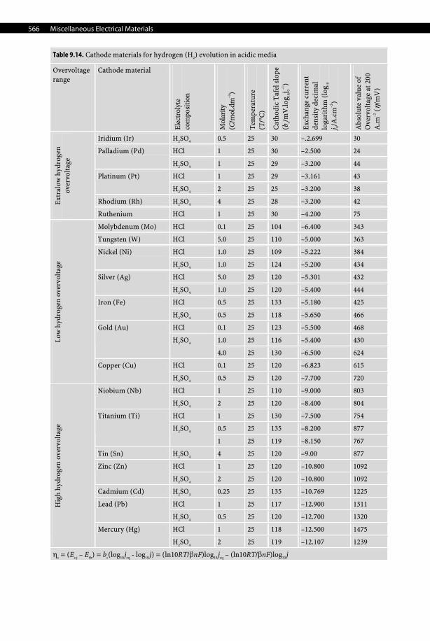
566 Miscellaneous Electrical Materials
Table 9.14. (continued)
Overvoltage range
Cathode material
Elec
trol
yte
com
posi
tion
Mol
arity
(C
/mol
.dm
–3)
Tem
pera
ture
(T
/°C
)
Cat
hodi
c T
afel
slo
pe
(bc/m
V.lo
g 10j 0–1
)
Exc
hang
e cu
rren
t de
nsit
y de
cim
al
loga
rith
m (
log 10
j 0/
A.c
m–2
)
Abs
olut
e va
lue
of
Ove
rvol
tage
at 2
00
A.m
–2 (
η/m
V)
Iridium (Ir) H2SO4 0.5 25 30 –.2.699 30
HCl 1 25 30 –2.500 24 Palladium (Pd)
H2SO4 1 25 29 –3.200 44
HCl 1 25 29 –3.161 43 Platinum (Pt)
H2SO4 2 25 25 –3.200 38
Rhodium (Rh) H2SO4 4 25 28 –3.200 42 Extr
alow
hyd
roge
n ov
ervo
ltag
e
Ruthenium HCl 1 25 30 –4.200 75
Molybdenum (Mo) HCl 0.1 25 104 –6.400 343
Tungsten (W) HCl 5.0 25 110 –5.000 363
HCl 1.0 25 109 –5.222 384 Nickel (Ni)
H2SO4 1.0 25 124 –5.200 434
HCl 5.0 25 120 –5.301 432 Silver (Ag)
H2SO4 1.0 25 120 –5.400 444
HCl 0.5 25 133 –5.180 425 Iron (Fe)
H2SO4 0.5 25 118 –5.650 466
HCl 0.1 25 123 –5.500 468
1.0 25 116 –5.400 430
Gold (Au)
H2SO4
4.0 25 130 –6.500 624
HCl 0.1 25 120 –6.823 615
Low
hyd
roge
n ov
ervo
ltag
e
Copper (Cu)
H2SO4 0.5 25 120 –7.700 720
HCl 1 25 110 –9.000 803 Niobium (Nb)
H2SO4 2 25 120 –8.400 804
HCl 1 25 130 –7.500 754
0.5 25 135 –8.200 877
Titanium (Ti)
H2SO4
1 25 119 –8.150 767
Tin (Sn) H2SO4 4 25 120 –9.00 877
HCl 1 25 120 –10.800 1092 Zinc (Zn)
H2SO4 2 25 120 –10.800 1092
Cadmium (Cd) H2SO4 0.25 25 135 –10.769 1225
HCl 1 25 117 –12.900 1311 Lead (Pb)
H2SO4 0.5 25 120 –12.700 1320
HCl 1 25 118 –12.500 1475
Hig
h hy
drog
en o
verv
olta
ge
Mercury (Hg)
H2SO4 2 25 119 –12.107 1239
ηc = (Ec,j – Eth) = bc(log10 jeq - log10 j) = (ln10RT/βnF)log10 jeq – (ln10RT/βnF)log10 j
Table 9.14. Cathode materials for hydrogen (H2) evolution in acidic media
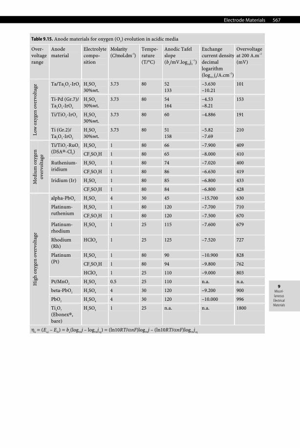
Electrode Materials 567
9 Miscel-laneous
Electrical Materials
Table 9.15. Anode materials for oxygen (O2) evolution in acidic media
Over-voltage range
Anode material
Electrolyte compo-sition
Molarity (C/mol.dm–3)
Tempe-rature (T/°C)
Anodic Tafel slope (ba/mV.log10j0
–1)
Exchange current densitydecimal logarithm (log10 j0/A.cm–2)
Overvoltage at 200 A.m–2 (mV)
Ta/Ta2O5-IrO2 H2SO4
30%wt. 3.73 80 52
133 –3.630 –10.21
101
Ti-Pd (Gr.7)/ Ta2O5-IrO2
H2SO4
30%wt. 3.73 80 54
164 –4.53 –8.21
153
Ti/TiO2-IrO2 H2SO4
30%wt. 3.73 80 60 –4.886 191
Low
oxy
gen
over
volt
age
Ti (Gr.2)/ Ta2O5-IrO2
H2SO4
30%wt. 3.73 80 51
158 –5.82 –7.69
210
H2SO4 1 80 66 –7.900 409 Ti/TiO2-RuO2 (DSA®-Cl2) CF3SO3H 1 80 65 –8.000 410
H2SO4 1 80 74 –7.020 400 Ruthenium-iridium CF3SO3H 1 80 86 –6.630 419
H2SO4 1 80 85 –6.800 433 Med
ium
oxy
gen
over
volt
age
Iridium (Ir)
CF3SO3H 1 80 84 –6.800 428
alpha-PbO2 H2SO4 4 30 45 –15.700 630
H2SO4 1 80 120 –7.700 710 Platinum-ruthenium CF3SO3H 1 80 120 –7.500 670
Platinum-rhodium
H2SO4 1 25 115 –7.600 679
Rhodium (Rh)
HClO4 1 25 125 –7.520 727
H2SO4 1 80 90 –10.900 828
CF3SO3H 1 80 94 –9.800 762
Platinum (Pt)
HClO4 1 25 110 –9.000 803
Pt/MnO2 H2SO4 0.5 25 110 n.a. n.a.
beta-PbO2 H2SO4 4 30 120 –9.200 900
PbO2 H2SO4 4 30 120 –10.000 996
Hig
h ox
ygen
ove
rvol
tage
Ti4O7 (Ebonex®, bare)
H2SO4 1 25 n.a. n.a. 1800
ηa = (Ea,j – Eth) = ba(log10 j – log10 jeq) = (ln10RT/αnF)log10 j – (ln10RT/αnF)log10 jeq
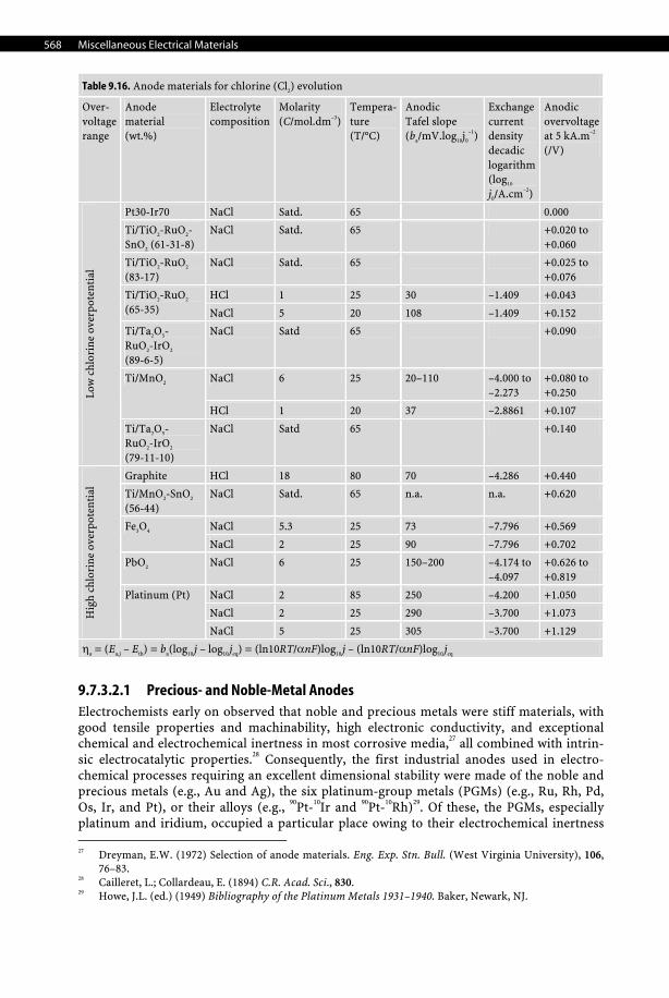
568 Miscellaneous Electrical Materials
Table 9.16. Anode materials for chlorine (Cl2) evolution
Over- voltage range
Anode material (wt.%)
Electrolyte composition
Molarity (C/mol.dm–3)
Tempera-ture (T/°C)
Anodic Tafel slope (ba/mV.log10j0
–1)
Exchange current density decadic logarithm (log10 j0/A.cm–2)
Anodic overvoltage at 5 kA.m–2 (/V)
Pt30-Ir70 NaCl Satd. 65 0.000
Ti/TiO2-RuO2- SnO2 (61-31-8)
NaCl Satd. 65 +0.020 to +0.060
Ti/TiO2-RuO2
(83-17) NaCl Satd. 65 +0.025 to
+0.076
HCl 1 25 30 –1.409 +0.043 Ti/TiO2-RuO2 (65-35) NaCl 5 20 108 –1.409 +0.152
Ti/Ta2O5- RuO2-IrO2 (89-6-5)
NaCl Satd 65 +0.090
NaCl 6 25 20–110 –4.000 to –2.273
+0.080 to +0.250
Ti/MnO2
HCl 1 20 37 –2.8861 +0.107
Low
chl
orin
e ov
erpo
tent
ial
Ti/Ta2O5- RuO2-IrO2 (79-11-10)
NaCl Satd 65 +0.140
Graphite HCl 18 80 70 –4.286 +0.440
Ti/MnO2-SnO2 (56-44)
NaCl Satd. 65 n.a. n.a. +0.620
NaCl 5.3 25 73 –7.796 +0.569 Fe3O4
NaCl 2 25 90 –7.796 +0.702
PbO2 NaCl 6 25 150–200 –4.174 to –4.097
+0.626 to +0.819
NaCl 2 85 250 –4.200 +1.050
NaCl 2 25 290 –3.700 +1.073 Hig
h ch
lori
ne o
verp
oten
tial
Platinum (Pt)
NaCl 5 25 305 –3.700 +1.129
ηa = (Ea,j – Eth) = ba(log10 j – log10 jeq) = (ln10RT/αnF)log10 j – (ln10RT/αnF)log10 jeq
9.7.3.2.1 Precious- and Noble-Metal Anodes Electrochemists early on observed that noble and precious metals were stiff materials, with good tensile properties and machinability, high electronic conductivity, and exceptional chemical and electrochemical inertness in most corrosive media,27 all combined with intrin-sic electrocatalytic properties.28 Consequently, the first industrial anodes used in electro-chemical processes requiring an excellent dimensional stability were made of the noble and precious metals (e.g., Au and Ag), the six platinum-group metals (PGMs) (e.g., Ru, Rh, Pd, Os, Ir, and Pt), or their alloys (e.g., 90Pt-10Ir and 90Pt-10Rh)29. Of these, the PGMs, especially platinum and iridium, occupied a particular place owing to their electrochemical inertness 27 Dreyman, E.W. (1972) Selection of anode materials. Eng. Exp. Stn. Bull. (West Virginia University), 106,
76–83. 28 Cailleret, L.; Collardeau, E. (1894) C.R. Acad. Sci., 830. 29 Howe, J.L. (ed.) (1949) Bibliography of the Platinum Metals 1931–1940. Baker, Newark, NJ.
Electrode Materials 569
9 Miscel-laneous
Electrical Materials
and intrinsic electrocatalytic activity. Actually, platinum is the most appropriate anode ma-terial for the preparation of persulfates, perchlorates, and periodates and for the regenera-tion of cerium (IV). However, the extremely high price of the bulk metal, which reached 1100 US$/oz. in early 2006, combined with its density (21,450 kg.m–3), has drastically re-stricted its industrial uses. However, early in the century there was an attempt to develop an inert anode for oxygen evolution in sulfuric-acid-based electrolytes. The anode was obtained by coating a cheaper base metal with a thin layer of platinum or iridium. These first compos-ite electrodes were patented in 1913 by Stevens.30,31 The thin platinum or iridium layers were electroplated onto a refractory metal such as tungsten or tantalum. The role of the platinum coating was to insure the electrical conduction of the base metal, even under anodic polari-zation. Despite its novelty, this bright idea was not industrially developed at that time be-cause it was impossible commercially to obtain these refractory metals, especially their mill products (e.g., plates, rods, sheet, and strips) needed for manufacturing large size industrial anodes. It was not until the 1960s that the first commercial platinized anodes appeared.
Besides the precious-metal anodes, early electrochemists used anodes made of two inex-pensive materials such as lead and carbon-based materials such as graphite. The lead and the graphite were actually the only cheap anode materials that were industrially used up to the 1960s.
9.7.3.2.2 Lead and Lead-Alloy Anodes Historically, the use of lead anodes resulted first from the widespread use of lead vessels in industrial manufacturing involving corrosive media such as the synthesis of sulfuric acid32 and later from the original studies in the lead-acid battery invented by Gaston Planté in 1859.33
Properties. Lead is a common and cheap metal, and the average price for lead of 99.99 wt.% purity is 0.980 US$/kg.34 Pure lead exhibits several attractive features, such as good electronic conductivity (20.64 μΩ.cm) and a good chemical and electrochemical corrosion resistance in numerous corrosive and oxidizing environments (e.g., chromates, sulfates, carbonates, and phosphates).35 This chemical and electrochemical inertness is due to the self-formation of a protective passivating layer. For instance, the corrosion rate of the pure metal in 50 wt.% sulfuric acid is 130 μm per year at 25°C. When the metal undergoes an anodic current density of 1 kA.m–2 in 60 wt.% sulfuric acid, the corrosion rate reaches only 9 mm per year.36,37 In fact, Pavlov38 has shown in acidic sulfate electrolytes that, with an increasing anodic polarization, first an insulating layer of anglesite (PbSO4) forms between 1.52 and 1.72 V/SHE, then a brown colored layer of semiconductive lead dioxide (PbO2) appears. If anodic polarization is increased further, an insulating film of PbO forms, preventing the current from flowing. The lead anode is characterized by a high anodic overpotential for the evolution of oxygen. It is important to note that among the dimorphic forms of PbO2 only the plattnerite with a rutile structure is electrocatalytic to oxygen evolution (cf. section on lead-dioxide anodes). Because
30 Stevens, R.H. (1913) Platinum-plated tungsten electrode. US Patent 1,077,894; November 4, 1913. 31 Stevens, R.H. (1913) Iridium-plated tungsten electrode. US Patent 1,077,920; November 4, 1913. 32 Lunge, G.; Naville, J. (1878) Traité de la grande industrie chimique. Tome I: acide sulfurique et oléum.
Masson & Cie, Paris. 33 Planté, G. (1859) Compt. Rend. Acad. Sci., 49, 221. 34 Metal Bulletin Weekly, May 8, 2006. 35 Greenwood, N.N.; Earnshaw, N. (1984) Chemistry of the Elements. Pergamon, Oxford, p. 435. 36 Beck, F. (1971) Lead dioxide-coated titanium anodes. German Patent 2,023,292; May 13, 1971. 37 Beck, F.; Csizi, G. (1971) Lead dioxide-titanium compound electrodes. German Patent 2,119,570; April 22,
1971. 38 Pavlov, D.; Rogachev, T. (1986) Mechanism of the action of silver and arsenic on the anodic corrosion of
lead and oxygen evolution at the lead/lead oxide (PbO2–x)/water/oxygen/sulfuric acid electrode system. Electrochim. Acta., 31(2), 241–249.
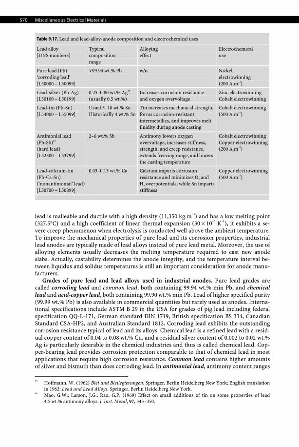
570 Miscellaneous Electrical Materials
Table 9.17. Lead and lead-alloy-anode composition and electrochemical uses
Lead alloy [UNS numbers]
Typical composition range
Alloying effect
Electrochemical use
Pure lead (Pb) ‘corroding lead’ [L50000 – L50099]
>99.94 wt.% Pb w/o Nickel electrowinning (200 A.m–2)
Lead-silver (Pb-Ag) [L50100 – L50199]
0.25–0.80 wt.% Ag39 (usually 0.5 wt.%)
Increases corrosion resistance and oxygen overvoltage
Zinc electrowinning Cobalt electrowinning
Lead-tin (Pb-Sn) [L54000 – L55099]
Usual 5–10 wt.% Sn Historically 4 wt.% Sn
Tin increases mechanical strength, forms corrosion-resistant intermetallics, and improves melt fluidity during anode casting
Cobalt electrowinning (500 A.m–2)
Antimonial lead (Pb-Sb)40 (hard lead) [L52500 – L53799]
2–6 wt.% Sb Antimony lowers oxygen overvoltage, increases stiffness, strength, and creep resistance, extends freezing range, and lowersthe casting temperature
Cobalt electrowinning Copper electrowinning (200 A.m–2)
Lead-calcium-tin (Pb-Ca-Sn) (‘nonantimonial’ lead)[L50700 – L50899]
0.03–0.15 wt.% Ca Calcium imparts corrosion resistance and minimizes O2 and H2 overpotentials, while Sn impartsstiffness
Copper electrowinning (500 A.m–2)
lead is malleable and ductile with a high density (11,350 kg.m–3) and has a low melting point (327.5°C) and a high coefficient of linear thermal expansion (30 × 10–6 K–1), it exhibits a se-vere creep phenomenon when electrolysis is conducted well above the ambient temperature. To improve the mechanical properties of pure lead and its corrosion properties, industrial lead anodes are typically made of lead alloys instead of pure lead metal. Moreover, the use of alloying elements usually decreases the melting temperature required to cast new anode slabs. Actually, castability determines the anode integrity, and the temperature interval be-tween liquidus and solidus temperatures is still an important consideration for anode manu-facturers.
Grades of pure lead and lead alloys used in industrial anodes. Pure lead grades are called corroding lead and common lead, both containing 99.94 wt.% min Pb, and chemical lead and acid-copper lead, both containing 99.90 wt.% min Pb. Lead of higher specified purity (99.99 wt.% Pb) is also available in commercial quantities but rarely used as anodes. Interna-tional specifications include ASTM B 29 in the USA for grades of pig lead including federal specification QQ-L-171, German standard DIN 1719, British specification BS 334, Canadian Standard CSA-HP2, and Australian Standard 1812. Corroding lead exhibits the outstanding corrosion resistance typical of lead and its alloys. Chemical lead is a refined lead with a resid-ual copper content of 0.04 to 0.08 wt.% Cu, and a residual silver content of 0.002 to 0.02 wt.% Ag is particularly desirable in the chemical industries and thus is called chemical lead. Cop-per-bearing lead provides corrosion protection comparable to that of chemical lead in most applications that require high corrosion resistance. Common lead contains higher amounts of silver and bismuth than does corroding lead. In antimonial lead, antimony content ranges
39 Hoffmann, W. (1962) Blei und Bleilegierungen. Springer, Berlin Heidelberg New York; English translation
in 1962: Lead and Lead Alloys. Springer, Berlin Heidelberg New York. 40 Mao, G.W.; Larson, J.G.; Rao, G.P. (1969) Effect on small additions of tin on some properties of lead
4.5 wt.% antimony alloys. J. Inst. Metal, 97, 343–350.
Electrode Materials 571
9 Miscel-laneous
Electrical Materials
from 0.5 to 25 wt.% Sb, but it is usually between 2 to 5 wt.% Sb. Antimony imparts greater hardness and strength. Lead-calcium alloys have replaced lead-antimony alloys in a number of applications. These alloys contain 0.03 to 0.15 wt.% Ca. More recently, aluminum has been added to calcium-lead and calcium-tin-lead alloys as a stabilizer for calcium. Adding tin to lead or lead alloys increases hardness and strength, but lead-tin alloys are more commonly used for their good melting, casting, and wetting properties. Tin gives an alloy the ability to wet and bond with metals such as steel and copper; unalloyed lead has poor wetting charac-teristics. The most common lead alloys used to manufacture industrial anodes together with their electrochemical applications are briefly summarized in Table 9.17.
Industrial applications. For those reasons, and despite its poor electrocatalytic properties and problems related to its toxicity arising with anodic dissolution, today lead anodes are the most common industrial anodes used worldwide for electrowinning metals from acidic sulfate electrolytes41 (e.g., Zn, Co, Ni) and in hexavalent chromium electroplating.42 The low price of lead anodes compared to titanium-coated electrodes and a service life in the range of 1 to 3 years are their major advantages. Moreover, the low melting temperature of lead and its alloys makes it possible to recycle in-house spent industrial lead anodes by simply remelting the discarded anodes and cast the recycled molten metal into new anode slabs. Zinc electrow-inning uses lead-silver. Pb-Ag is the standard because cobalt addition cannot be used. The silver alloy imparts some corrosion resistance to the base lead. Lead-based anodes are used because of their low cost and robustness. But the major drawbacks are sludge generation leading to product quality issues and high oxygen overpotential, i.e., higher power costs. Copper electrowinning uses lead-calcium-tin. Lead-calcium-tin is favored to avoid the cost of silver addition. Stabilization of Pb-Ca-Sn anodes is ensured by the careful addition of co-balt (II) as depolarizer in the electrowinning electrolyte. In the electrolytic production of manganese metal, silver-lead anodes (1 wt.% Ag) are used in producing electrolytic metallic manganese, which results in anode sliming of 0.38 to 0.45 tonnes per tonne of Mn. Slime of manganese and lead compounds is a process waste that engenders a number of problems:
(i) environment pollution by waste products; (ii) unproductive raw-material consumption, resulting in an increase in the overall volume
of facilities and capital investments; (iii) high specific energy consumption during preparation of additional quantities of man-
ganese-containing solutions for electrolysis baths; (iv) unpredictable anode destruction caused by active corrosion along waterlines; (v) frequent cleanup of anodes and baths (once every 20 to 24 days), replacement of dia-
phragms, and remelting of anodes.
Recent developments. Some work is still being carried out to overcome some of the drawbacks of industrial lead anodes. For instance, the Japanese subsidiary of De Nora, Permelec Co., has developed a reinforced lead anode for the electrowinning of zinc from sulfate baths. This anode is made of a skin portion formed by a conventional silver-lead alloy and a stiffening reinforcing component made of titanium or zirconium mesh. The reduction in the thickness of the anodes, which is made possible by the provision of the reinforcing member, results in substantial savings in the amount of silver-bearing lead that is immobi-lized and a substantial reduction in the mass of the bulk anode. Later, Eltech Systems Corp. introduced its new patented technology,43 known by the brand name Mesh-on-LeadTM (MOL)
41 De Nora, O. (1962) Anodes for use in the evolution of chlorine. British Patent 902,023; July 25, 1962. 42 Nidola, A. (1995) Technologie di cromatura galvanica a spessore. Rivista AIFM: Galvanotecnica e nuove
finiture, 5, 203–218. 43 Brown, C.W.; Bishara, J.I.; Ernes, L.M.; Getsy, A.W.; Hardee, K.L.; Martin, B.L.; Pohto, G.R. (2002) Lead
electrode structure having mesh surface. US Patent 6,352,622; March 5, 2002.
572 Miscellaneous Electrical Materials
anode. The MOL anode is in fact a composite structure obtained by attaching disposable electrocatalytically active titanium mesh to existing lead anodes. Hence, it combines the benefits of a standard lead anode with power savings of a precious-metal-oxide-coated tita-nium found typically in dimensionally stable anodes (see DSA). The MOL product is still being developed to overcome its major drawback, cost. This new anode is specifically desig-nated for replacing Pb-Ca-Sn anodes for primary copper electrowinning operations (e.g., SXEW process). The MOL concept was demonstrated with full-scale anodes at several pre-mier commercial tankhouses. During these demonstrations MOL anodes exhibited numerous performance advantages relative to standard Pb-Ca-Sn anodes: they reduced specific energy consumption due to lower oxygen evolution overpotential, improved cathode quality, mini-mized lead-sludge generation, eliminated cobalt addition as a result of stabilized lead sub-strate, and improved current efficiency due to reduced short circuiting.44
Failure modes. In acidic sulfate baths, the most common failure mode of lead anodes consists of the formation of a thick solid and intermediate passivating layer of PbSO4 and PbO2 that can grow up to 5 mm thick and that eventually flakes off, leaving patches of freshly exposed surface. This deactivation of the lead anode is accompanied by two major draw-backs of industrial electrolysis: loss of faradic efficiency, usually below 90% for zinc and below 95% for cobalt, and an uneven and dendritic aspect of the electrodeposited metal usually contaminated by traces of lead. Another important failure mode occurs due to the deleterious effect of manganese (II) cations. Actually, the presence of manganous cations as impurities in many electrolyte streams may cause important secondary anodic reactions to occur. During the anodic process manganous cations Mn2+ may either react at the anode surface to form soluble permanganate species (MnO4
–) or insoluble manganese dioxide (MnO2) that passivates the anode surface and then impedes the proper evolution of oxygen. Eventually, flakes on the anode can detach as slime that contains oxides and/or sulfates, which are the major source of lead contamination in electrowinned cathodes. In copper electrowinning, Co (II) is often used as depolarizer for the oxygen evolution reaction. How-ever, cobalt can not be used during zinc electrowinning because it affects the overall current efficiency.
9.7.3.2.3 Carbon Anodes History. Carbon-based electrode materials (e.g., carbon, semigraphite, and graphite) have been used in various electrochemical technologies since the beginning of electrochemistry, including electroanalysis, energy storage devices, and electrosynthesis. For instance, due to its chemical inertness toward hydrochloric acid and hydrogen chloride, graphite was the early anode material selected for HCl electrolysis for producing chlorine gas.45 This process, initially developed in Germany during World War II46 by Holemann and Messner at IG Far-ben Industrie,47,48 was continued in the 1950s by De Nora-Monsanto49,50 and Hoechst-Uhde.51,52
44 Moats, M.; Hardee, K.; Brown, Jr., C. (2003) Mesh-on-Lead anodes for copper electrowinning. JOM, 55(7),
46–48 45 Isfort, H. (1985) State of the art after 20 years experience with industrial hydrochloric acid electrolysis.
DECHEMA Monographien, 98, 141–155. 46 Gardiner, W.C. (1946) Hydrochloric Acid Electrolysis at Wolfen. Field Information Agency, Technical
(FIAT) Report No. 832, US Office of Military Government for Germany. 47 Gardiner, W.C. (1947) Hydrochloric acid electrolysis. Chem. Eng., 54(1), 100–101. 48 Holemann, H. (1962) The hydrochloric acid electrolysis. Chem. Ing. Techn., 34, 371–376. 49 Gallone, P.; Messner, G. (1965) Direct electrolysis of hydrochloric acid. Electrochem. Technol., 3(11–12),
321–326. 50 Messner, G. (1966) Cells for the production of chlorine from hydrochloric acid. US Patent 3,236,760;
February 22, 1966. 51 Grosselfinger, F.B. (1964) New chlorine source: by-product hydrochloric acid. Chem. Eng., 71(19), 172–174. 52 Donges, E.; Janson, H.G. (1966) Chem. Ing. Techn., 38, 443.
Electrode Materials 573
9 Miscel-laneous
Electrical Materials
Structure. As a general rule, carbon-based materials have similar microstructures consist-ing of a planar network of a six-membered aromatic-forming layered structure with sp2-hybridized carbon atoms trigonally bonded to one another. The crystallite size and extent of microstructural order can vary from material to material (i.e., edge-to-basal-plane ratio), which has important implications for electron-transfer kinetics.
Properties. Carbon-based electrodes are attractive because carbon is a cheap material with an excellent chemical inertness, and it is easy to machine and has a low bulk density (2260 kg.m–3). Furthermore, there is a great diversity of commercially available products (e.g., graphite, pyrolytic, impervious, or glassy) and in several forms (e.g., fibers, cloths, blacks, powders, or reticulated). The graphite variety, despite its anisotropy, high electrical resistivity (1375 μΩ.cm), and extreme brittleness, was once widely used for the electrolysis of brines. Graphite is highly corrosion resistant to concentrated hydrochloric acid even at the high anodic potential required for producing chlorine. Corrosion is not detectable if the concentration of hydrochloric acid is always maintained above 20 wt.% HCl during elec-trolysis. Carbon anodes are also the only appropriate anode material in certain processes where no other materials exhibit both a low cost and a satisfactory corrosion resistance. Actually, several industrial electrolytic processes performed in molten-salt electrolytes con-tinue to use carbon anodes; these processes are: the electrowinning of aluminum by the Hall–Heroult process, the electrolytic production of alkali metals (e.g., Na, Li) and alkali-earth metals (e.g., Be, Mg), and finally the electrolytic production of elemental fluorine. However, the use of carbon anodes in the chlor-alkali process for the production of chlorine gas has now been discontinued due to the replacement by modern and more efficient an-odes. In fact, in the 1960s, the improvement of the chlor-alkali processes (e.g., mercury cath-ode cell and diaphragm cell) required great efforts in research and development. The re-search was essentially focused on improving graphite anodes, which had some serious drawbacks: first, the nondimensional stability of the carbon anodes during electrolysis led to continuous increases in the interelectrode gap, which caused an ohmic drop; second, it had a high chlorine evolution overpotential; and third, it had a very short service life (i.e., 6 to 24 months) due to the corrosion by the chlorine and the inescapable traces of oxygen, which formed chlorinated hydrocarbons and carbon dioxide. These efforts led to the birth of the third generation of industrial dimensionally stable anodes (vide infra).
Failure modes. Due to its lamellar structure, graphite severely corrodes due to the inter-calation of anions between graphene planes such as sulfate or perchlorate during anodic discharge, while alkali-metal cations and ammonium intercalate when cathodically polarized leads to severe exfoliation of the electrode materials. The degradation of carbon-based mate-rials depends on the electrolyte, the nature of the carbon materials, and the concentration of intercalating species. Once the graphite particles float on the electrolyte surface, they can lead to serious electrical continuity issues (i.e., short circuit), especially in molten-salt elec-trolytes that are denser than graphite.
9.7.3.2.4 Lead Dioxide (PbO2) Structure. Lead dioxide exhibits two polymorphic forms: (i) scrutinyite (α-PbO2) with ortho-rhombic crystals (a = 497.1 pm, b = 595.6 pm, and c = 543.8 pm) with a density of 9867 kg.m–3, and (ii) plattnerite (β-PbO2) with tetragonal crystals (a = 495.25 pm and c = 338.63 pm) having a rutile-type structure and a density of 9564 kg.m–3.
Properties. Only plattnerite has attractive features for electrochemical applications such as a low electrical resistivity (40 to 50 μΩ.cm), a good chemical and electrochemical corrosion resistance in sulfates media even at low pH, and a high overvoltage for the evolu-tion of oxygen in sulfuric- and nitric-acid-containing electrolytes while it withstands chlo-rine evolution in hydrochloric acid. In fact, the more electrochemically active phase consists
574 Miscellaneous Electrical Materials
of a nonstoichiometric lead dioxide with the empirical chemical formula PbOn (with 1.4 < n < 2). A review of its preparation is presented by Thangappan et al.53
Preparation. Lead dioxide forms on pure lead, in dilute sulfuric acid, when polarized anodically at electrode potentials ranging from +1.5 to +1.8 V/SHE. Hence, industrially, lead-dioxide anodes are prepared by in situ anodization of a pure lead anode carried out at 20°C. The lead anode and a copper cathode are immersed in an undivided cell containing a dilute sulfuric acid (98 g.dm–3 H2SO4) flowing with a rate ranging from 5 to 10 dm3.min–1, and the electrodeposition is conducted galvanostatically by applying an anodic current density of 100 A.m–2 for 30 min. The inherent brittleness of the PbO2 ceramic coating on soft lead can be overcome by electrodepositing anodically lead dioxide onto inert and stiff substrates such as titanium, niobium, tantalum, graphite, and Ebonex®. These supported anodes, that is, Ti/PbO2 and Ta/PbO2,
54 are now commercially available.55,56 The anodic electrodeposition of a layer of PbO2 is usually conducted in an undivided cell with a copper cathode and a station-ary or flowing electrolyte consisting of dilute sulfuric acid (98 g.dm–3 H2SO4) containing 1 mol.dm–3 lead (II) nitrate with minute amounts of copper (II) or nickel (II) nitrate. Copper and nickel cations are used as cathodic depolarizers to impede the deleterious electrodeposi-tion of lead on the cathode. Prior to coating, the metal substrate is first sandblasted to in-crease roughness and enhance the coating adhesion; this is followed by chemical etching. Etching is conducted, for instance, in boiling concentrated hydrochloric acid for titanium and its alloys or in cold concentrated hydrofluoric acid for niobium and tantalum. Etching re-moves the passivation layer that is always present on refractory metals. Then lead dioxide is electrodeposited galvanostatically at 200 A.m–2 for several hours to reach anode loadings of several grams per square meter. The PbO2 coating obtained is smooth, dense, hard, uniform, and free of pinholes and adheres to the surface of the substrate material. Sometimes a thin intermediate platinum layer is inserted between the base metal and the PbO2 coating to en-hance the service life by preventing the undermining process. Finally, for particular applica-tions requiring bulk ceramic anodes, the electrodeposited lead dioxide can also be crushed, melted, and cast into intricate shapes.
Applications. PbO2-based anodes are used for their inertness and low cost and when the oxidation should be carried out without the competitive evolution of oxygen. PbO2 anodes were once used as a substitute for the conventional graphite and platinum electrodes for regenerating potassium dichromate and in the production of chlorates and perchlorates.57 These anodes were also extensively used in hydrometallurgy as oxygen anodes for electro-plating copper and zinc in sulfate baths58,59,60 and in organic electrosynthesis for the produc-tion of glyoxilic acid from oxalic acid using sulfuric acid as supporting electrolyte.61
Failure modes. For lead dioxide supported on lead, the mismatch of strength and thermal expansion between the lead metal substrate and its lead-dioxide ceramic coating leads to flak-ing and spalling with loss of coating. As mentioned previously, a thin platinum underlayer can
53 Thangappan, R.; Nachippan, S.; Sampath, S. (1970) Lead dioxide-graphite electrode. Ind. Eng. Chem. Prod.
Res. Dev., 9(4), 563–567. 54 Pohl, J.P.; Richert, H. (1980) In: Trasatti, S. (ed.) Electrodes of Conductive Metallic Oxides, Part A. Elsevier,
Amsterdam, Chap. 4, pp. 183–220. 55 De Nora, O. (1962) Anodes for use in the evolution of chlorine. British Patent 902,023; July 25, 1962. 56 Kuhn, A.T. (1976) The electrochemical evolution of oxygen on lead dioxide anodes. – Chemistry & Indus-
try, 20, 867–871. 57 Grigger, J.C.; Miller, H.C.; Loomis, F.D. (1958) Lead dioxide anode for commercial use. J. Electrochem.
Soc., 105, 100–102. 58 Engelhardt, V.; Huth, M. (1909) Electrolytic recovery of zinc. US Patent 935,250; September 28, 1909. 59 Gaunce, F.S. (1964) Treatment of lead or lead alloy electrodes. French Patent 1,419,356; November 26, 1964. 60 Higley, L.W.; Dressel, W.M.; Cole, E.R. (1976) U.S. Bureau of Mines, Report No. R8111. 61 Goodridge, F.; Lister, K.; Plimley, R.; Scott, K. (1980) Scale-up studies of the electrolytic reduction of
oxalic to glyoxylic acid. J. Appl. Electrochem., 10(1), 55–60.
Electrode Materials 575
9 Miscel-laneous
Electrical Materials
delay the catastrophic undermining process induced by the loss of coating, but usually the use of lead-dioxide-coated titanium anodes solves this issue but increases capital costs. Another failure mode occurs when manganese (II) cations are present that form insoluble manganese dioxide (MnO2). Eventually, flakes on the anode can detach, entraining the coating and form-ing slimes at the bottom of the electrolyzer.
9.7.3.2.5 Manganese Dioxide (MnO2) Manganese dioxide was used for a long time following the work of Huth,62 where hard and dense anodes of MnO2 were obtained by forming a main body of the MnO2 anode and then repeatedly treating this body with Mn(NO3)2 and heating it to decompose the nitrate and form additional MnO2. These anodes were once used extensively in hydrometallurgy for the elec-trowinning or electroplating of zinc,63 copper, and finally nickel in sulfate baths. They are prepared by solution impregnation-calcination64 or by anodization in a sulfuric solution con-taining manganous cations. However, they never have the same full expansion of lead dioxide owing to their high corrosion rate under extreme conditions, that is, at high temperature, high pH, and elevated anodic current density. Nevertheless, some improvements have been made to increase their stability. Feige prepared a supported Ti/MnO2 anode made by sintering tita-nium and lead particles with MnO2.
65 De Nora et al. obtained a Ti/MnO2-type anode by the application of the classical painting-thermal decomposition procedure employed for the preparation of DSA®.66
9.7.3.2.6 Spinel (AB2O4)- and Perovskite (ABO3)-Type Oxides Structure. It is well known that some ceramic oxides of the inner transition metals (e.g., Mn, Fe, Co, and Ni) with a spinel-type structure (AIIBIII
2O4) or, to a lesser extent, a perovskite-type structure (AIIBIVO3) are electrical conductors with electrocatalytic activities when doped with Li, Ni, and Co. Moreover, being sufficiently stable in corrosive electrolytes, they were devel-oped as good candidates for the development of oxygen-evolving electrodes. Spinels are oxides with the general formula IV(A1–xBx)
VI(AxB2–x)O4, where the divalent cations are denoted A = Mg2+, Fe2+, Ni2+, Co2+, and Zn2+ and trivalent cations B = Al3+, Fe3+, Cr3+, and V3+. Hence two types of spinel structure must be distinguished: normal spinels with x = 0, meaning that all the divalent cations occupy tetrahedral sites, and inverse spinels with x = 1. Of these, rods of pure magnetite (Fe3O4) or its doped form67 obtained by casting molten iron oxides have been used as industrial anodes since 1870. Apart from magnetite and ferrites, today other classes of spinels have been investigated such as cobaltites and chromites. Due to their better electrocatalytic properties and fewer health and safety issues, cobaltites (e.g., MCo2O4 with M= Mg, Cu, and Zn) are now preferred and are the only ones being developed.
Properties. These anodes, despite their good chemical inertness and electrochemical stability under high positive potential,68,69 have nevertheless two main drawbacks: they are
62 Huth, M. (1919) Anodes of solid manganese peroxide. US Patent 1,296,188; March 4, 1919. 63 Bennett, J.E.; O’Leary, K.J. (1973) Oxygen anodes. US Patent 3,775,284; November 27, 1973. 64 Ohzawa, K.; Shimizu, K.; Takasue, T. (1967) Insoluble electrode for electrolysis. US Patent 3,616,302;
February 27, 1967. 65 Feige, N.G. (1974) Method for producing a coated anode. US Patent 3,855,084; December 17, 1974. 66 De Nora, O.; Nidola, O.; Spaziante, P.M. (1978) Manganese dioxide electrodes. US Patent 4,072,586;
February 7, 1978. 67 Kuhn, A.T.; Wright, P.M. In: Kuhn, A.T. (ed.) (1971) Industrial Electrochemical Processes, Chap. 14.
Elsevier, New York. 68 Matsumura, Takashi; Itai, R.; Shibuya, M.; Ishi, G. (1968) Electrolytic manufacture of sodium chlorate
with magnetite anodes. Electrochem. Technol., 6(11–12), 402–404. 69 Itai, R.; Shibuya, M.; Matsumura, T.; Ishi, G. (1971) Electrical resistivity of magnetite anodes. J. Electro-
chem. Soc., 118(10), 1709–1711.
576 Miscellaneous Electrical Materials
brittle, which means a ceramic must be supported on a stiff metal substrate, and they exhibit very high electrical resistivities (27,000 μΩ.cm) with respect to other electrode materials.
Preparation. These oxides are usually produced by firing metallic precursors (e.g., ni-trates, oxalates) in a moderately oxidizing atmosphere (e.g., steam, or argon-carbon dioxide mixture) at moderate temperatures (700 to 900°C). For reinforcing a brittle ceramic, these oxides can be used supported on a stiff base metal such as titanium.70 Sometimes, such as for PbO2 anodes, an thin intermediate layer of platinum is deposited between the base metal and the magnetite to enhance the service life and delay the undermining process.
9.7.3.2.7 Ebonex®(Ti4O7 and Ti5O9) Since 1983, the date of the original patent of Hayfield71 from IMI (Marston) describing a novel semiconductive electrode material that was prepared from substoichiometric oxides of titanium. These ceramics have attracted particular attention in the electrochemical com-munity.72,73 Soon after, the intellectual property related to the suboxides of titanium was purchased by the company Ebonex Technologies Incorporated (ETI), which was itself a subsidiary of ICI (Americas) and commercialized under the trade name Ebonex®.74 Later, in 1992, the company was renamed Atraverda Limited. Bulk ceramic electrodes are manufac-tured in various forms (e.g., plates, tubes, rods, honeycombs, fibers, powders, and pellets) and grades (e.g., vitreous and porous). From a crystallochemical point of view, these ceram-ics consist of substoichiometric oxides of titanium with the Andersson–Magnéli crystal lat-tice structure75 and the general chemical formula TinO2n–1, where n is an integer equal to or greater than 4 (e.g.,Ti4O7, Ti5O9, Ti6O11, Ti7O13, Ti8O15, Ti9O17, and Ti10O19). They are usually prepared by thermal reduction at 1300°C of pure TiO2 by hydrogen, methane, or carbon monoxide, or a blend of titanium dioxide and titanium metal powder. These oxides have all comparably elevated electronic conductivity similar, and in some cases superior, to that of graphite (e.g., 630 μΩ.cm for Ti4O7 compared with 1375 μΩ.cm for graphite). From a corro-sion point of view, Ebonex® exhibits an unusual chemical inertness in several corrosive media such as strong, oxidizing, or reducing mineral acids (e.g., HCl, H2SO4, HNO3, and even HF). The anomalous high resistance to HF, and fluoride anions that usually readily attack titania even in dilute solutions, seems due to the difference in the lattice structure and the absence of hydrates. Ebonex® has also served as substrate for electrodepositing with a plati-num coating76 and been used as a platinized anode.77 These anodes show no major differ-ences with bulk platinum anodes.
Moreover, Pletcher and coworkers succeeded in electroplating coatings of metals such as Cu, Au, Ni, Pd, and Pt without any pretreatment of the substrate. In addition, by contrast
70 Hayes, M.; Kuhn, A.T. (1978) The preparation and behavior of magnetite anodes. J. Appl. Electrochem.,
8(4), 327−332. 71 Hayfield, P.C.S. (1983) Electrode material, electrode and electrochemical cell. US Patent 4,422,917; De-
cember 27, 1983. 72 Baez, V.B.; Graves, J.E.; Pletcher, D. (1992) The reduction of oxygen on titanium oxide electrodes. J. Elec-
troanal. Chem., 340(1–2), 273–86. 73 Graves, J.E.; Pletcher, D.; Clarke, R.L.; Walsch, F.C. (1991) The electrochemistry of Magneli phase titanium
oxide ceramic electrodes. I. The deposition and properties of metal coatings. J. Appl. Electrochem., 21(10), 848–857.
74 Clarke, R.; Pardoe, R. (1992) Applications of ebonex conductive ceramics in effluent treatment. In: Gen-ders, D.; Weinberg, N. (eds.) Electrochemistry for a Cleaner Environment. Electrosynthesis Company, Amherst, NY, pp. 349–363.
75 Andersson, S.; Collen, B.; Kuylienstierna, U.; Magneli, A. Acta Chem. Scand., 11, 1641. 76 Farndon, E.E.; Pletcher, D.; Saraby-Reintjes, A. (1997) The electrodeposition of platinum onto a conduct-
ing ceramic, Ebonex. Electrochimica Acta, 42(8), 1269–1279. 77 Farndon, E.E.; Pletcher, D. (1997) Studies of platinized Ebonex electrodes. Electrochimica Acta, 42(8),
1281–1285.
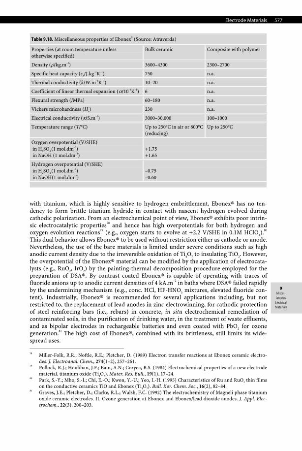
Electrode Materials 577
9 Miscel-laneous
Electrical Materials
Table 9.18. Miscellaneous properties of Ebonex® (Source: Atraverda)
Properties (at room temperature unless otherwise specified)
Bulk ceramic Composite with polymer
Density (ρ/kg.m–3) 3600–4300 2300–2700
Specific heat capacity (cP/J.kg–1K–1) 750 n.a.
Thermal conductivity (k/W.m–1K–1) 10–20 n.a.
Coefficient of linear thermal expansion (α/10–6K–1) 6 n.a.
Flexural strength (/MPa) 60–180 n.a.
Vickers microhardness (Hv) 230 n.a.
Electrical conductivity (κ/S.m–1) 3000–30,000 100–1000
Temperature range (T/°C) Up to 250°C in air or 800°C (reducing)
Up to 250°C
Oxygen overpotential (V/SHE) in H2SO4 (1 mol.dm–3) in NaOH (1 mol.dm–3)
+1.75 +1.65
Hydrogen overpotential (V/SHE) in H2SO4 (1 mol.dm–3) in NaOH(1 mol.dm–3)
–0.75 –0.60
with titanium, which is highly sensitive to hydrogen embrittlement, Ebonex® has no ten-dency to form brittle titanium hydride in contact with nascent hydrogen evolved during cathodic polarization. From an electrochemical point of view, Ebonex® exhibits poor intrin-sic electrocatalytic properties78 and hence has high overpotentials for both hydrogen and oxygen evolution reactions79 (e.g., oxygen starts to evolve at +2.2 V/SHE in 0.1M HClO4).80 This dual behavior allows Ebonex® to be used without restriction either as cathode or anode. Nevertheless, the use of the bare materials is limited under severe conditions such as high anodic current density due to the irreversible oxidation of Ti4O7 to insulating TiO2. However, the overpotential of the Ebonex® material can be modified by the application of electrocata-lysts (e.g., RuO2, IrO2) by the painting-thermal decomposition procedure employed for the preparation of DSA®. By contrast coated Ebonex® is capable of operating with traces of fluoride anions up to anodic current densities of 4 kA.m–2 in baths where DSA® failed rapidly by the undermining mechanism (e.g., conc. HCl, HF-HNO3 mixtures, elevated fluoride con-tent). Industrially, Ebonex® is recommended for several applications including, but not restricted to, the replacement of lead anodes in zinc electrowinning, for cathodic protection of steel reinforcing bars (i.e., rebars) in concrete, in situ electrochemical remediation of contaminated soils, in the purification of drinking water, in the treatment of waste effluents, and as bipolar electrodes in rechargeable batteries and even coated with PbO2 for ozone generation.81 The high cost of Ebonex®, combined with its brittleness, still limits its wide-spread uses. 78 Miller-Folk, R.R.; Noftle, R.E.; Pletcher, D. (1989) Electron transfer reactions at Ebonex ceramic electro-
des. J. Electroanal. Chem., 274(1–2), 257–261. 79 Pollock, R.J.; Houlihan, J.F.; Bain, A.N.; Coryea, B.S. (1984) Electrochemical properties of a new electrode
material, titanium oxide (Ti4O7). Mater. Res. Bull., 19(1), 17–24. 80 Park, S.-Y.; Mho, S.-I.; Chi, E.-O.; Kwon, Y.-U.; Yeo, I.-H. (1995) Characteristics of Ru and RuO2 thin films
on the conductive ceramics TiO and Ebonex (Ti4O7). Bull. Kor. Chem. Soc., 16(2), 82–84. 81 Graves, J.E.; Pletcher, D.; Clarke, R.L.; Walsh, F.C. (1992) The electrochemistry of Magneli phase titanium
oxide ceramic electrodes. II. Ozone generation at Ebonex and Ebonex/lead dioxide anodes. J. Appl. Elec-trochem., 22(3), 200–203.
578 Miscellaneous Electrical Materials
9.7.3.2.8 Noble-Metal-Coated Titanium Anodes (NMCT) During the 1950s and 1960s, at the peak of expansion of the American and Russian aircraft and space programs and with the development of nuclear power plants, industrial processes for the production of refractory metals (e.g., Ti, Zr, Hf, Nb, and Ta) reached commercial scale. These processes, like the Kroll process,82 made reactive metals with a wide range of alloy compositions available for the first time. This development brought several advantages: a reduction in production costs, the standardization of alloy grades, and a great effort in R&D for using these metals beyond their original aircraft and nuclear applications. At this stage, all the difficulties associated with preparing anodes of refractory metals coated with precious metals vanished, and the idea invented 40 years ago by Stevens reappeared. Hence, niobium- and tantalum-platinized anodes were prepared following the works of Rhoda83 and Rosen-blatt84 in 1955. In the latter patent, a layer of platinum was obtained on tantalum by the ther-mal decomposition of H2PtCl6 in an inert atmosphere. This thermal treatment, which was conducted between 800 and 1000°C, gave a thin interdiffusion layer of a few micrometers, consisting of an alloy between Ta and Pt. Furthermore, titanium, now commercially available due to the strong demand for turbine blades in aircraft engines, was studied both from a corrosion and electrochemical point of view at ICI by Cotton.85,86 The study showed that the exceptional resistance of titanium to corrosion in seawater was due to the valve action property of its oxide, which allowed the metal to be protected under anodic polarization by an insulating layer of rutile (TiO2). It is only in 1957 that Beer87 at Magneto Chemie (The Netherlands) and Cotton88,89 with the help of Angell at ICI (UK) showed independently but concurrently that attaching rhodium or platinum at the surface of titanium, either by electro-plating or by spot welding, provided sufficient electrical conductivity to the base metal that it could be polarized anodically despite its passivation. It was assumed that anodic current passed through platinum or rhodium metal. These rhodized or platinized titanium bielec-trodes were named noble metal coated titanium (NMCT). During the following decade, NMCTs were actively developed through a partnership between ICI and Magneto Chemie with the close contribution of other companies such as Inco, Engelhard,90,91 and IMI-Kynock.92 Other firms such as W.C. Heraeus,93 Metallgeselschaft,94 and Texas Instruments95 have also worked independently on the subject. The best preparation procedure involves electroplating with platinum or rhodium because the electrodeposition allows for smooth and nonporous deposits with a good throwing power without requiring an expensive amount of platinum.96
82 Kroll, W.J. (1940) The production of ductile titanium. Trans. Electrochem. Soc., 112, 35–47. 83 Rhoda, R.N. (1952) Electroless palladium plating. Trans. Inst. Met. Finish., 36(3), 82–85. 84 Rosenblatt, E.F.; Cohn, J.G. (1955) Platinum-metal-coated tantalum anodes. US Patent 2,719,797; October
4, 1955. 85 Cotton, J.B. (1958) Anodic polarization of titanium. Chem. & Ind., 3, 492–493. 86 Cotton, J.B. (1958) The corrosion resistance of titanium. Chem. Ind., 3, 640–646. 87 Beer, H.B. (1960) Precious-metal anode with a titanium core. British Patent 855,107; November 11, 1960. 88 Cotton, J.B.; Williams, E.C.; Barber, A.H. (1957) Titanium electrodes plated with platinum-group metals
for electrolytic processes and cathodic protection. Electrodes. British Patent 877,901; July 17, 1957. 89 Cotton, J.B. (1958) Platinum-faced titanium for electrochemical anodes. A new electrode material for
impressed current cathodic protection. Platinum Metals Rev., 2, 45–47. 90 Haley, A.J.; Keith, C.D.; May, J.E. (1969) Two-layer metallic electrodes. US Patent 3,461,058. 91 May, J.E.; Haley, A.J. (1970) Electroplating with auxiliary platinum-coated tungsten anodes. US Patent
3,505,178; April 7, 1970. 92 Cotton, J.B.; Hayfield, P.C.S. (1965) Electrodes and methods of making same. British Patent 1,113,421;
May 15, 1965. 93 Muller, P.; Speidel, H. (1960) New forms of platinum-tantalum electrodes. Metall. 14, 695–696. 94 Schleicher, H.W. (1963) Electrodes for electrolytic processes. British Patent 941,177; November 6, 1963. 95 Whiting, K.A. (1964) Cladding copper articles with niobium or tantalum and platinum outside. US Patent
3,156,976; November 17, 1964. 96 Balko, E.N. (1991) Electrochemical Applications of the Platinum Group: Metal Coated Anodes. In: Hartley,
F.R. (ed.) Chemistry of the Platinum Group Metals: Recent Developments. Elsevier, New York.
Electrode Materials 579
9 Miscel-laneous
Electrical Materials
The electroplating baths contain a platinum salt such as the so-called P-salt, the hexachloro-platinic acid, or the sodium hexachloroplatinate (IV).97 The electrocatalytic coating consists of platinum and rhodium present in their metallic forms. However, both rhodium and plati-num have high chlorine overvoltage (e.g. 300 mV for Rh and 486 mV for Pt at 10 kA.m–2) and exhibit a slight corrosion with the rate depending on the electrolyte and the nature of bath impurities (e.g., Cl–, F–, organics).
9.7.3.2.9 Platinized Titanium and Niobium Anodes (70/30 Pt/Ir) The improvement of the noble-metal-coated-titanium anodes was the starting point of the study and preparation of platinized titanium anodes by the thermal decomposition of a precursor with the pioneering work of, for example, Angell and Deriaz, both from ICI.98,99 The precursor consisted of a given mixture of hexachloroplatinic (H2PtCl6) and hexachloroiridic acids (H2IrCl6) dissolved in an appropriate organic solvent (e.g., linalool, isopropanol, or ethyl acetoacetate). Prior to applying the painting solution, the titanium substrate was thoroughly sandblasted to increase roughness and chemically etched to remove the passivating layer. Etchants included various chemicals such as hot concentrated hydrochloric acid, hot 10 wt.% oxalic acid, and hot 30 wt.% sulfuric acid. After each application the treated piece underwent a long thermal treatment at high temperature in air between 400 and 500°C. At that temperature thermal oxidation of the underlying titanium substrate is negligible. This original protocol was inspired by Taylor’s works100 used in the 1930s to obtain reflective coatings of Pt on glass for the manufacture of optical mirrors. The study of the thermal decomposition of these par-ticular painting solutions was conducted by Hopper101 in 1923 and more recently by Kuo102 in 1974. Other companies interested in platinized titanium anodes prepared by thermal decom-position were Engelhard103 and Ionics.104 After long-term trials, the formulation and procedure were finally optimized. These anodes were initially commercialized in 1968 by IMI (Marston) under the trade name K-type® or 70/30 Pt/Ir.105 For optimum performance, the commercially pure titanium must be from ASTM grade 1 or 2 with equiaxed grain sizes ranging between 30 and 50 μm. The electrocatalytic coating consists of platinum and rhodium present in their metallic forms either as separate phases or as platinum-iridium intermetallic. In fact, after thermal decomposition titanium is coated with a highly divided mixture of metal oxides con-sisting essentially of 70 wt.% PtOx to 30 wt.% IrOx. The common anode loading is 10 g.m–2. Later, Millington106 observed that niobium, tantalum, and even tungsten107 could also be used as substrates, but they were only considered by certain suppliers108 when titanium showed deficiencies owing to their greater cost. These anodes were rapidly used in numerous proc-esses requiring a long service life under severe conditions. For example, they were 97 Lowenheim, F.A. (1974) Modern Electroplating, 3rd ed. Wiley, New York. 98 Angell, C.H.; Deriaz, M.G. (1961) Improvements in or relating to a method for the production of assem-
blies comprising titanium. British Patent 885,819; December 28, 1961. 99 Angell, C.H.; Deriaz, M.G. (1965) Improvements in or relating to a method for the production of assem-
blies comprising titanium. British Patent 984,973; March 3, 1965. 100 Taylor, J.F. (1929) J. Opt. Soc. Am., 18, 138. 101 Hopper, R.T. (1923) Ceram. Ind. (June). 102 Kuo, C.Y. (1974) Electrical applications of thin-films produced by metallo-organic deposition. – Solid
State Technol. 17(2), 49–55. 103 Anderson, E.P. (1961) Method for preparing anodes for cathodic protection systems. US Patent 2,998,359;
August 29, 1961. 104 Tirrel, C.E. (1964) Method for making non corroding electrode. US Patent 3,117,023; January 7, 1964. 105 Hayfield, P.C.S.; Jacob, W.R. (1980) In: Coulter, M.O. (ed.) Modern Chlor-Alkali Technology. Ellis Hor-
wood, London, Chap. 9, pp. 103–120. 106 Millington, J.P. (1974) Lead dioxide electrode. British Patent 1,373,611; November 13, 1974. 107 May, J.E.; Haley, Jr., A.J. (1970) Electroplating with auxiliary platinum-coated tungsten anodes. US Patent
3,505,178; April 7, 1970. 108 Haley, Jr., A.J. (1967) Engelhardt Ind. Tech. Bull., 7, 157.
580 Miscellaneous Electrical Materials
employed for the cathodic protection of immersed plants such as oil rigs, storage tanks, and subterranean pipe-lines,109,110 in the electrolytic processes for the production of sodium hy-pochlorite,111 electrodialysis, for regeneration of Ce(IV) in perchloric or nitric acid,112 and for oxidation of sulfuric acid in peroxodisulfuric acid.113 It is interesting to note that De Nora reg-istered a patent on a Pt-coated anode in which the base metal was a ferrosilicon with some amounts of chromium.114 Other formulations consisted of clad platinum metal on a copper-clad titanium or niobium core by roll bonding or a sandwich of platinum-titanium (or nio-bium)-copper. This technique, which provides a thick, dense, and impervious platinum coat-ing, is now commercialized by Anomet in the USA for the cathodic protection of oil rigs. This continuous research effort, always developed under pressure from industry, resulted in the 1960s in a new generation of anodes that are still widely used in all electrochemical fields and are discussed below. Nevertheless, although platinized titanium electrodes were found active, they still were found to be unsatisfactory for chlorine production. It was for this reason that Beer patented a new type of anode, discussed in the next section.
9.7.3.2.10 Dimensionally Stable Anodes (DSA®) for Chlorine Evolution In the 1960s, Henri Bernard Beer, who worked at Permelec115and the Italian team of Bianchi, Vittorio De Nora, Gallone, and Nidola, started studying the electrocatalytic behavior of mixed metal oxides and nitride coatings for the evolution of chlorine and oxygen.116,117 These oxides were obtained by the calcination of precursors but in an oxidizing atmosphere (i.e., air or pure oxygen). These RuO2-based anodes or so-called “ruthenized titanium anodes,” composed of mixed metal oxides (TiO2-RuO2) coated on a titanium metal, have been devel-oped with great success since 1965, the year of Beer’s famous patent.118 At this stage, the selection of ruthenium was made only based on the low cost of the metal and its commercial availability. These electrodes were later protected by several patents.119,120,121,122 It was the birth of the activated titanium anode (ATA), also called oxide-coated titanium anode (OCTA), designation now obsolete and modernized in the 1990 to mixed metal oxides (MMO). These anodes are characterized by a geometrical stability and a constant potential over a long time (more than 2 to 3 years). It is this dimensional stability in comparison with the graphite anodes that gives it its actual trade name: dimensionally stable anodes (the acronym DSA® is
109 Cotton, J.B.; Williams, E.C.; Barber, A.H. (1961) Improvements relating to electrodes and uses thereof.
British Patent 877,901; September 20, 1961. 110 Anderson, E.P. (1961) Method for preparing anodes for cathodic protection systems. US Patent 2,998,359;
August 29, 1961. 111 Adamson, A.F.; Lever, B.G.; Stones, W.F. (1963) J. Appl. Chem., 13, 483. 112 Ibl, N.; Kramer, R.; Ponto, L.; Robertson, P.M. (1979) Electroorganic Synthesis Technology. AIChE Sympo-
sium Series No. 185 75, 45. 113 Rakov, A.A.; Veselovskii, V.I.; Kasatkin, E.V.; Potapova, G.F.; Sviridon, V.V. (1977) Zh. Prikl. Khim. 50,
334. 114 Bianchi, G.; Gallone, P.; Nidola, A.E. (1970) Composite anodes. US Patent 3,491,014; January 20, 1970. 115 Beer, H.B. (1963) Noble metal coated titanium electrode and method for making and using it. US Patent
3,096,272; July 2, 1963. 116 Bianchi, G.; De Nora, V.; Gallone, P.; Nidola, A. (1971) Titanium or tantalum base electrodes with applied
titanium or tantalum oxide face activated with noble metals or noble metal oxides. US Patent 3,616,445; October 26, 1971.
117 Bianchi, G.; De Nora, V.; Gallone, P.; Nidola, A. (1976) Valve metal electrode with valve metal oxide semi-conductive face. US Patent 3,948,751; April 6, 1976.
118 Beer, H.B. (1966) Electrode and method for making the same. US Patent 3,234,110; February 8, 1966. 119 Beer, H.B. (1966) Method of chemically plating base layers with precious metals of the platinum group.
US Patent 3,265,526; August 9, 1966. 120 Beer, H.B. (1972) Electrode and coating therefor. US Patent 3,632,498; January 4, 1972. 121 Beer, H.B. (1973) Electrode having a platinum metal oxide. US Patent 3,711,385; January 13, 1973. 122 Beer, H.B. (1973) Electrode and coating therefor. US Patent 3,751,291; August 7, 1973.
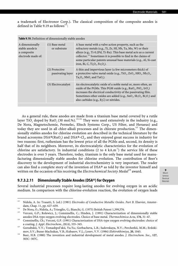
Electrode Materials 581
9 Miscel-laneous
Electrical Materials
a trademark of Electronor Corp.). The classical composition of the composite anodes is defined in Table 9.19 as follows123:
Table 9.19. Definition of dimensionally stable anodes
(1) Base metal or substrate
A base metal with a valve action property, such as the refractory metals (e.g., Ti, Zr, Hf, Nb, Ta, Mo, W) or their alloys (e.g., Ti-0.2Pd, Ti-Ru). This base metal acts as a current collector.124 Sometimes it is possible to find in the claims of some particular patents unusual base materials (e.g., Al, Si-cast iron, Bi, C, Ti4O7, Fe3O4).
(2) Protective passivating layer
A thin and impervious layer (a few micrometers thick) of a protective valve metal oxide (e.g., TiO2, ZrO2, HfO2, Nb2O5, Ta2O5, NbO2 and TaO2).
A dimensionally stable anode is a composite electrode made of:
(3) Electrocatalyst An electrocatalytic oxide of a noble metal or, more often, an oxide of the PGMs. This PGM oxide (e.g., RuO2, PtOx, IrO2) increases the electrical conductivity of the passivating film. Sometimes other oxides are added (e.g., SnO2, Sb2O5, Bi2O3) and also carbides (e.g., B4C) or nitrides.
As a general rule, these anodes are made from a titanium base metal covered by a rutile layer TiO2 doped by RuO2 (30 mol.%).125,126 They were used extensively in the industry (e.g., De Nora, Magnetochemie, Permelec, Eltech Systems Corp., US Filter, and Heraeus) and today they are used in all chlor-alkali processes and in chlorate production.127 The dimen-sionally stables anodes for chlorine evolution are described in the technical literature by the brand acronyms DSA®(RuO2) and DSA®-Cl2, and they enjoyed great success in industry for two reasons: first, ruthenium has the lowest price of all the PGMs and, second, its density is half that of its neighbors. Moreover, its electrocatalytic characteristics for the evolution of chlorine are satisfactory. In industrial conditions (2 to 4 kA.m–2) the service life of these electrodes is over 5 years. Therefore, today, titanium is the only base metal used for manu-facturing dimensionally stable anodes for chlorine evolution. The contribution of Beer’s discovery to the development of industrial electrochemistry is very important. The reader can also find a complete story of the invention of DSA® as told by the inventor himself and written on the occasion of his receiving the Electrochemical Society Medal128 award.
9.7.3.2.11 Dimensionally Stable Anodes (DSA®) for Oxygen Several industrial processes require long-lasting anodes for evolving oxygen in an acidic medium. In comparison with the chlorine-evolution reaction, the evolution of oxygen leads
123 Nidola, A. In: Trasatti, S. (ed.) (1981) Electrodes of Conductive Metallic Oxides. Part B. Elsevier, Amster-
dam, Chap. 11, pp. 627–659. 124 De Nora, O.; Nidola, A.; Trisoglio, G.; Bianchi, G. (1973) British Patent 1,399,576. 125 Vercesi, G.P.; Rolewicz, J.; Comninellis, C.; Hinden, J. (1991) Characterization of dimensionally stable
anodes DSA-type oxygen evolving electrodes. Choice of base metal. Thermochimica Acta, 176, 31–47. 126 Comninellis, Ch.; Vercesi, G.P. (1991) Characterization of DSA-type oxygen evolving electrodes: choice of
a coating. J. Appl. Electrochem., 21(4), 335–345. 127 Gorodtskii, V.V.; Tomashpol’skii, Yu.Ya.; Gorbacheva, L.B.; Sadovskaya, N.V.; Percherkii, M.M.; Erdoki-
mov, S.V.; Busse-Machukas, V.B.; Kubasov, V.L.; Losev, V.V. (1984) Elektrokhimiya, 20, 1045. 128 Beer, H.B. (1980) The invention and industrial development of metal anodes. J. Electrochem. Soc., 127,
303C−307C.
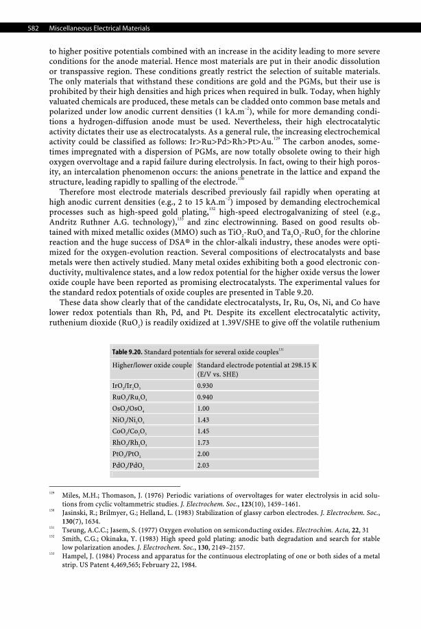
582 Miscellaneous Electrical Materials
to higher positive potentials combined with an increase in the acidity leading to more severe conditions for the anode material. Hence most materials are put in their anodic dissolution or transpassive region. These conditions greatly restrict the selection of suitable materials. The only materials that withstand these conditions are gold and the PGMs, but their use is prohibited by their high densities and high prices when required in bulk. Today, when highly valuated chemicals are produced, these metals can be cladded onto common base metals and polarized under low anodic current densities (1 kA.m–2), while for more demanding condi-tions a hydrogen-diffusion anode must be used. Nevertheless, their high electrocatalytic activity dictates their use as electrocatalysts. As a general rule, the increasing electrochemical activity could be classified as follows: Ir>Ru>Pd>Rh>Pt>Au.129 The carbon anodes, some-times impregnated with a dispersion of PGMs, are now totally obsolete owing to their high oxygen overvoltage and a rapid failure during electrolysis. In fact, owing to their high poros-ity, an intercalation phenomenon occurs: the anions penetrate in the lattice and expand the structure, leading rapidly to spalling of the electrode.130
Therefore most electrode materials described previously fail rapidly when operating at high anodic current densities (e.g., 2 to 15 kA.m–2) imposed by demanding electrochemical processes such as high-speed gold plating,132 high-speed electrogalvanizing of steel (e.g., Andritz Ruthner A.G. technology),133 and zinc electrowinning. Based on good results ob-tained with mixed metallic oxides (MMO) such as TiO2-RuO2 and Ta2O5-RuO2 for the chlorine reaction and the huge success of DSA® in the chlor-alkali industry, these anodes were opti-mized for the oxygen-evolution reaction. Several compositions of electrocatalysts and base metals were then actively studied. Many metal oxides exhibiting both a good electronic con-ductivity, multivalence states, and a low redox potential for the higher oxide versus the lower oxide couple have been reported as promising electrocatalysts. The experimental values for the standard redox potentials of oxide couples are presented in Table 9.20.
These data show clearly that of the candidate electrocatalysts, Ir, Ru, Os, Ni, and Co have lower redox potentials than Rh, Pd, and Pt. Despite its excellent electrocatalytic activity, ruthenium dioxide (RuO2) is readily oxidized at 1.39V/SHE to give off the volatile ruthenium
129 Miles, M.H.; Thomason, J. (1976) Periodic variations of overvoltages for water electrolysis in acid solu-
tions from cyclic voltammetric studies. J. Electrochem. Soc., 123(10), 1459–1461. 130 Jasinski, R.; Brilmyer, G.; Helland, L. (1983) Stabilization of glassy carbon electrodes. J. Electrochem. Soc.,
130(7), 1634. 131 Tseung, A.C.C.; Jasem, S. (1977) Oxygen evolution on semiconducting oxides. Electrochim. Acta, 22, 31 132 Smith, C.G.; Okinaka, Y. (1983) High speed gold plating: anodic bath degradation and search for stable
low polarization anodes. J. Electrochem. Soc., 130, 2149–2157. 133 Hampel, J. (1984) Process and apparatus for the continuous electroplating of one or both sides of a metal
strip. US Patent 4,469,565; February 22, 1984.
Table 9.20. Standard potentials for several oxide couples131
Higher/lower oxide couple Standard electrode potential at 298.15 K(E/V vs. SHE)
IrO2/Ir2O3 0.930
RuO2/Ru2O3 0.940
OsO2/OsO4 1.00
NiO2/Ni2O3 1.43
CoO2/Co2O3 1.45
RhO2/Rh2O3 1.73
PtO3/PtO2 2.00
PdO3/PdO2 2.03
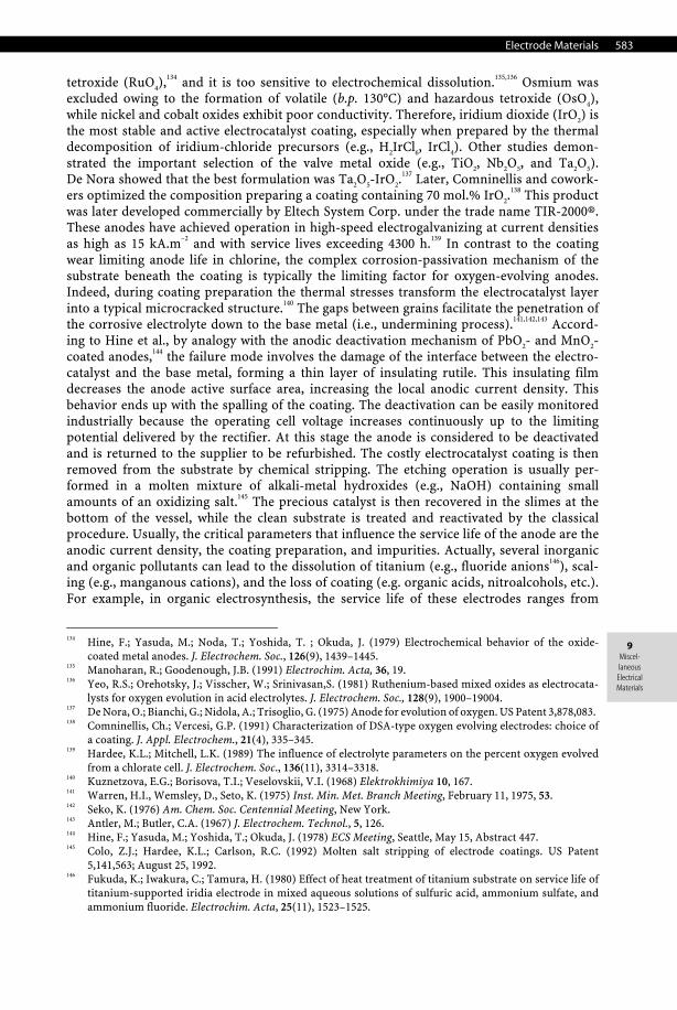
Electrode Materials 583
9 Miscel-laneous
Electrical Materials
tetroxide (RuO4),134 and it is too sensitive to electrochemical dissolution.135,136 Osmium was excluded owing to the formation of volatile (b.p. 130°C) and hazardous tetroxide (OsO4), while nickel and cobalt oxides exhibit poor conductivity. Therefore, iridium dioxide (IrO2) is the most stable and active electrocatalyst coating, especially when prepared by the thermal decomposition of iridium-chloride precursors (e.g., H2IrCl6, IrCl4). Other studies demon-strated the important selection of the valve metal oxide (e.g., TiO2, Nb2O5, and Ta2O5). De Nora showed that the best formulation was Ta2O5-IrO2.
137 Later, Comninellis and cowork-ers optimized the composition preparing a coating containing 70 mol.% IrO2.
138 This product was later developed commercially by Eltech System Corp. under the trade name TIR-2000®. These anodes have achieved operation in high-speed electrogalvanizing at current densities as high as 15 kA.m–2 and with service lives exceeding 4300 h.139 In contrast to the coating wear limiting anode life in chlorine, the complex corrosion-passivation mechanism of the substrate beneath the coating is typically the limiting factor for oxygen-evolving anodes. Indeed, during coating preparation the thermal stresses transform the electrocatalyst layer into a typical microcracked structure.140 The gaps between grains facilitate the penetration of the corrosive electrolyte down to the base metal (i.e., undermining process).141,142,143 Accord-ing to Hine et al., by analogy with the anodic deactivation mechanism of PbO2- and MnO2-coated anodes,144 the failure mode involves the damage of the interface between the electro-catalyst and the base metal, forming a thin layer of insulating rutile. This insulating film decreases the anode active surface area, increasing the local anodic current density. This behavior ends up with the spalling of the coating. The deactivation can be easily monitored industrially because the operating cell voltage increases continuously up to the limiting potential delivered by the rectifier. At this stage the anode is considered to be deactivated and is returned to the supplier to be refurbished. The costly electrocatalyst coating is then removed from the substrate by chemical stripping. The etching operation is usually per-formed in a molten mixture of alkali-metal hydroxides (e.g., NaOH) containing small amounts of an oxidizing salt.145 The precious catalyst is then recovered in the slimes at the bottom of the vessel, while the clean substrate is treated and reactivated by the classical procedure. Usually, the critical parameters that influence the service life of the anode are the anodic current density, the coating preparation, and impurities. Actually, several inorganic and organic pollutants can lead to the dissolution of titanium (e.g., fluoride anions146), scal-ing (e.g., manganous cations), and the loss of coating (e.g. organic acids, nitroalcohols, etc.). For example, in organic electrosynthesis, the service life of these electrodes ranges from
134 Hine, F.; Yasuda, M.; Noda, T.; Yoshida, T. ; Okuda, J. (1979) Electrochemical behavior of the oxide-
coated metal anodes. J. Electrochem. Soc., 126(9), 1439–1445. 135 Manoharan, R.; Goodenough, J.B. (1991) Electrochim. Acta, 36, 19. 136 Yeo, R.S.; Orehotsky, J.; Visscher, W.; Srinivasan,S. (1981) Ruthenium-based mixed oxides as electrocata-
lysts for oxygen evolution in acid electrolytes. J. Electrochem. Soc., 128(9), 1900–19004. 137 De Nora, O.; Bianchi, G.; Nidola, A.; Trisoglio, G. (1975) Anode for evolution of oxygen. US Patent 3,878,083. 138 Comninellis, Ch.; Vercesi, G.P. (1991) Characterization of DSA-type oxygen evolving electrodes: choice of
a coating. J. Appl. Electrochem., 21(4), 335–345. 139 Hardee, K.L.; Mitchell, L.K. (1989) The influence of electrolyte parameters on the percent oxygen evolved
from a chlorate cell. J. Electrochem. Soc., 136(11), 3314–3318. 140 Kuznetzova, E.G.; Borisova, T.I.; Veselovskii, V.I. (1968) Elektrokhimiya 10, 167. 141 Warren, H.I., Wemsley, D., Seto, K. (1975) Inst. Min. Met. Branch Meeting, February 11, 1975, 53. 142 Seko, K. (1976) Am. Chem. Soc. Centennial Meeting, New York. 143 Antler, M.; Butler, C.A. (1967) J. Electrochem. Technol., 5, 126. 144 Hine, F.; Yasuda, M.; Yoshida, T.; Okuda, J. (1978) ECS Meeting, Seattle, May 15, Abstract 447. 145 Colo, Z.J.; Hardee, K.L.; Carlson, R.C. (1992) Molten salt stripping of electrode coatings. US Patent
5,141,563; August 25, 1992. 146 Fukuda, K.; Iwakura, C.; Tamura, H. (1980) Effect of heat treatment of titanium substrate on service life of
titanium-supported iridia electrode in mixed aqueous solutions of sulfuric acid, ammonium sulfate, and ammonium fluoride. Electrochim. Acta, 25(11), 1523–1525.
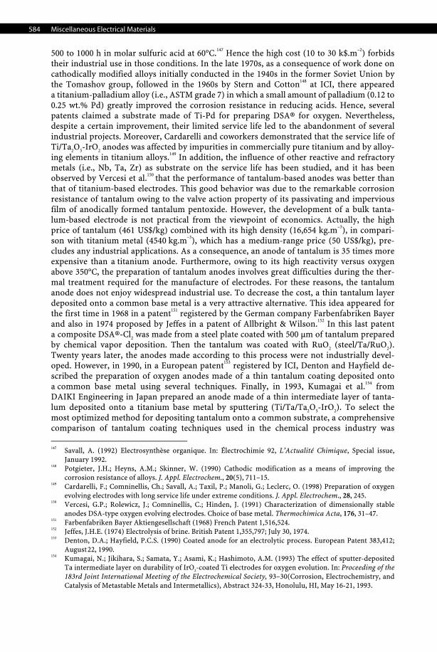
584 Miscellaneous Electrical Materials
500 to 1000 h in molar sulfuric acid at 60°C.147 Hence the high cost (10 to 30 k$.m–2) forbids their industrial use in those conditions. In the late 1970s, as a consequence of work done on cathodically modified alloys initially conducted in the 1940s in the former Soviet Union by the Tomashov group, followed in the 1960s by Stern and Cotton148 at ICI, there appeared a titanium-palladium alloy (i.e., ASTM grade 7) in which a small amount of palladium (0.12 to 0.25 wt.% Pd) greatly improved the corrosion resistance in reducing acids. Hence, several patents claimed a substrate made of Ti-Pd for preparing DSA® for oxygen. Nevertheless, despite a certain improvement, their limited service life led to the abandonment of several industrial projects. Moreover, Cardarelli and coworkers demonstrated that the service life of Ti/Ta2O5-IrO2 anodes was affected by impurities in commercially pure titanium and by alloy-ing elements in titanium alloys.149 In addition, the influence of other reactive and refractory metals (i.e., Nb, Ta, Zr) as substrate on the service life has been studied, and it has been observed by Vercesi et al.150 that the performance of tantalum-based anodes was better than that of titanium-based electrodes. This good behavior was due to the remarkable corrosion resistance of tantalum owing to the valve action property of its passivating and impervious film of anodically formed tantalum pentoxide. However, the development of a bulk tanta-lum-based electrode is not practical from the viewpoint of economics. Actually, the high price of tantalum (461 US$/kg) combined with its high density (16,654 kg.m–3), in compari-son with titanium metal (4540 kg.m–3), which has a medium-range price (50 US$/kg), pre-cludes any industrial applications. As a consequence, an anode of tantalum is 35 times more expensive than a titanium anode. Furthermore, owing to its high reactivity versus oxygen above 350°C, the preparation of tantalum anodes involves great difficulties during the ther-mal treatment required for the manufacture of electrodes. For these reasons, the tantalum anode does not enjoy widespread industrial use. To decrease the cost, a thin tantalum layer deposited onto a common base metal is a very attractive alternative. This idea appeared for the first time in 1968 in a patent151 registered by the German company Farbenfabriken Bayer and also in 1974 proposed by Jeffes in a patent of Allbright & Wilson.152 In this last patent a composite DSA®-Cl2 was made from a steel plate coated with 500 μm of tantalum prepared by chemical vapor deposition. Then the tantalum was coated with RuO2 (steel/Ta/RuO2). Twenty years later, the anodes made according to this process were not industrially devel-oped. However, in 1990, in a European patent153 registered by ICI, Denton and Hayfield de-scribed the preparation of oxygen anodes made of a thin tantalum coating deposited onto a common base metal using several techniques. Finally, in 1993, Kumagai et al.154 from DAIKI Engineering in Japan prepared an anode made of a thin intermediate layer of tanta-lum deposited onto a titanium base metal by sputtering (Ti/Ta/Ta2O5-IrO2). To select the most optimized method for depositing tantalum onto a common substrate, a comprehensive comparison of tantalum coating techniques used in the chemical process industry was
147 Savall, A. (1992) Electrosynthèse organique. In: Électrochimie 92, L’Actualité Chimique, Special issue,
January 1992. 148 Potgieter, J.H.; Heyns, A.M.; Skinner, W. (1990) Cathodic modification as a means of improving the
corrosion resistance of alloys. J. Appl. Electrochem., 20(5), 711–15. 149 Cardarelli, F.; Comninellis, Ch.; Savall, A.; Taxil, P.; Manoli, G.; Leclerc, O. (1998) Preparation of oxygen
evolving electrodes with long service life under extreme conditions. J. Appl. Electrochem., 28, 245. 150 Vercesi, G.P.; Rolewicz, J.; Comninellis, C.; Hinden, J. (1991) Characterization of dimensionally stable
anodes DSA-type oxygen evolving electrodes. Choice of base metal. Thermochimica Acta, 176, 31–47. 151 Farbenfabriken Bayer Aktiengesellschaft (1968) French Patent 1,516,524. 152 Jeffes, J.H.E. (1974) Electrolysis of brine. British Patent 1,355,797; July 30, 1974. 153 Denton, D.A.; Hayfield, P.C.S. (1990) Coated anode for an electrolytic process. European Patent 383,412;
August 22, 1990. 154 Kumagai, N.; Jikihara, S.; Samata, Y.; Asami, K.; Hashimoto, A.M. (1993) The effect of sputter-deposited
Ta intermediate layer on durability of IrO2-coated Ti electrodes for oxygen evolution. In: Proceeding of the 183rd Joint International Meeting of the Electrochemical Society, 93–30(Corrosion, Electrochemistry, and Catalysis of Metastable Metals and Intermetallics), Abstract 324-33, Honolulu, HI, May 16-21, 1993.
Electrode Materials 585
9 Miscel-laneous
Electrical Materials
recently reviewed by Cardarelli et al.155 Moreover, the same authors developed anodes made from a thin tantalum layer deposited onto a common base metal (e.g. copper, nickel, or stainless steel) coated with an electrocatalytic mixture of oxides Ta2O5-IrO2 produced by calcination. The performances of these anodes (stainless steel/Ta/IrO2) are identical to that obtained with solid tantalum base metal (Ta/IrO2).156
9.7.3.2.12 Synthetic Diamond Electrodes Structure. The use of synthetic semiconductive diamond thin films in electrochemistry has only recently been reported.157 Former designations such as diamondlike carbon (DLC) are now obsolete and so are not used in this book. By contrast with its other carbon allotropes, in diamond each carbon atom is tetrahedrally bonded to four other carbons using sp3-hybrid orbitals.
Properties. Diamond has several attractive properties including the highest Young’s modulus, thermal conductivity, and hardness of all solid materials, high electrical resistance, excellent chemical inertness, high electron and hole mobilities, and a wide optical transpar-ency range (Section 12.5.1). The pure material is a wide bandgap insulator (Eg = 5.5 eV) and offers advantages for electronic applications under extreme environmental conditions. Nev-ertheless, when doped with boron, the material exhibits p-type semiconductive properties (i.e., IIb type diamond). Actually, doped diamond thin films can possess electronic conduc-tivity ranging from that of an insulator at low doping levels to those of a good semiconduc-tor for highly doped films (i.e., impurity level >1019 atoms.cm–3). For instance, synthetic diamond thin films grown using hot-filament or microwave-assisted chemical vapor deposi-tion can be doped to as high as 10,000 ppm at. of boron per carbon atom, resulting in films with resistivities of less than 105 μΩ.cm. Boron atoms that are electron acceptors form a band located roughly 0.35 eV above the valence band edge. At room temperature, some of the valence-band electrons are thermally promoted to this intermediate level, leaving free elec-trons in the dopant band and holes, or vacancies, in the valence band to support the flow of current. In addition, boron-doped diamond thin films commonly possess a rough, polycrys-talline morphology with grain boundaries at the surface and a small-volume fraction of nondiamond carbon impurity. Hence, the electrical conductivity of the film surface and the bulk is influenced by the boron-doping level, the grain boundaries, and the impurities. Sev-eral interesting electrochemical properties distinguish boron-doped diamond thin films from conventional carbon-based electrodes. As a general rule, boron-doped diamond films exhibit voltammetric background currents and double-layer capacitances up to an order of magnitude lower than for glassy carbon. The residual or background current density in 0.1 M KCl measured by linear sweep voltammetry is less than 50 μA.cm–2 between –1.0 and +1.0 V/SHE. This indicates that the diamond-electrolyte interface is almost ideally polariz-able. The evolution of hydrogen starts at roughly –1.75 V/SHE. The electrochemical span or working potential window, defined as the potentials at which the anodic and cathodic cur-rents reach 250 μA.cm–2, is 3.5 V for diamond compared to 2.5 V for glassy carbon. The over-potentials for hydrogen and oxygen evolution reactions are directly related to the nondia-mond carbon impurity content. The higher the fraction of nondiamond carbon present, the lower the overpotentials for both these reactions. The double-layer capacitance for BDD in
155 Cardarelli, F.; Taxil, P.; Savall, A. (1996) Tantalum protective thin coating techniques for the chemical
process industry: molten salts electrocoating as a new alternative. Int. J. Refract. Metals Hard Mater., 14, 365.
156 Cardarelli, F.; Comninellis, Ch.; Leclerc, O.; Saval, A.; Taxil, P.; Manoli, G. (1997) Fabrication of an anode with enhanced durability and method for making the same. PCT International Patent Application WO 97/43465A1.
157 Swain, G.; Ramesham, R. (1993) The electrochemical activity of boron-doped polycrystalline diamond thin film electrodes. Anal. Chem., 65(4), 345–351.
586 Miscellaneous Electrical Materials
1 M KCl ranges from 4 to 8 μF.cm–2 over a 2-V potential window. There is a general trend to-ward increasing capacitance with more positive potentials, which is characteristic for p-type semiconductor electrode-electrolyte interfaces.158 These capacitance values are comparable in magnitude to those observed for the basal plane of highly oriented pyrolytic graphite and significantly lower than those for glassy carbon (25 to 35 μF.cm–2). The capacitance versus potential profile shape and magnitude for diamond is largely independent of the electrolyte composition and solution pH. On the other hand, boron-doped diamond electrodes have good electrochemical activity without any pretreatment.
Preparation. Diamond thin films can be prepared on a substrate from thermal decompo-sition of dilute mixtures of a hydrocarbon gas (e.g., methane) in hydrogen using one of sev-eral energy-assisted CVD methods, the most popular being hot-filament and microwave discharge.159,160 The growth methods mainly differ in the manner in which the gas thermal activation is accomplished. Typical growth conditions are C/H ratios of 0.5 to 2 vol%, reduce pressures ranging from 1.33 to 13.3 kPa, a substrate temperature between 800 and 1000°C, and microwave powers of 1 to 1.3 kW, or filament temperatures of ca. 2100°C, depending on the method used. The film grows by nucleation at rates in the 0.1- to 1-μm/h range. For the substrates to be continuously coated with diamond, the nominal film thickness must be 1 μm. Wafer diameters of several centimeters can easily be coated in most modern reactors. Boron doping is accomplished from the gas phase by mixing a boron-containing gas such as dibo-rane (B2H6) with the source gases, or from the solid state by gasifying a piece of hexagonal-boron nitride (h-BN).161 Prior to deposition the substrate must be pretreated by cleaning it with a series of solvents, and nucleation sites are provided by embedding tiny diamond par-ticles that are polished with a diamond paste. Hydrogen plays an important role in all of the growth methods as it prevents surface reconstruction from a saturated sp3-hybridized dia-mond microstructure to an unsaturated sp2-hybridized graphite microstructure; it also sup-presses the formation of nondiamond carbon impurity, and it prevents several species from forming reactive radicals.
9.7.4 Electrodes for Corrosion Protection and Control
Apart from batteries, fuel cells, and industrial electrolyzers, corrosion protection and control is another field in which electrode materials occupy an important place.
9.7.4.1 Cathodes for Anodic Protection Anodic protection162 is a modern electrochemical technique for protecting metallic equip-ment used in the chemical-process industry against corrosion and handling highly corrosive chemicals (e.g., concentrated sulfuric and orthophosphoric acids). The technique consists in impressing a very low anodic current (i.e., usually 10 μA.m–2) on a piece of metallic equip-ment (e.g., tanks, thermowells, columns) to protect against corrosion. This anodic polariza-tion puts the electrochemical potential of the metal in the passivity region of its Pourbaix
158 Alehashem, S.; Chambers, F.; Strojek, J.W.; Swain, G.M.; Ramesham, R. (1995) New applications of dia-
mond thin film technology in electro chemical systems. Anal. Chem., 67, 2812. 159 Angus, J.C.; Hayman, C.C. (1988) Low-pressure, metastable growth of diamond and “diamondlike”
phases. Science 241, 913–921. 160 Argoitia, A.; Angus, J.C.; Ma, J.S.; Wang, L.; Pirouz, P.; Lambrecht, W.R.L. (1994) Pseudomorphic stabili-
zation of diamond on non-diamond substrates. J. Mater. Res., 9, 1849. 161 Vinokur, N.; Miller, B.; Avyigal, Y.; Kalish, R. (1996) Electrochemical behavior of boron-doped diamond
electrodes. J. Electrochem. Soc., 143(10), L238–L240. 162 Riggs, Jr., O.L.; Locke, C.E. (1981) Anodic Protection: Theory and Practice in the Prevention of Corrosion.
Plenum, New York.
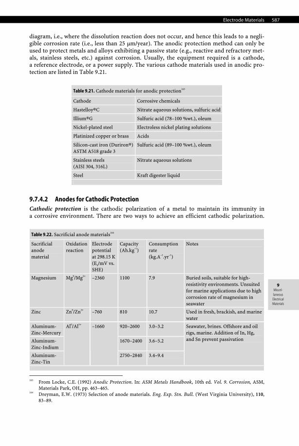
Electrode Materials 587
9 Miscel-laneous
Electrical Materials
diagram, i.e., where the dissolution reaction does not occur, and hence this leads to a negli-gible corrosion rate (i.e., less than 25 μm/year). The anodic protection method can only be used to protect metals and alloys exhibiting a passive state (e.g., reactive and refractory met-als, stainless steels, etc.) against corrosion. Usually, the equipment required is a cathode, a reference electrode, or a power supply. The various cathode materials used in anodic pro-tection are listed in Table 9.21.
Table 9.21. Cathode materials for anodic protection163
Cathode Corrosive chemicals
Hastelloy®C Nitrate aqueous solutions, sulfuric acid
Illium®G Sulfuric acid (78–100 %wt.), oleum
Nickel-plated steel Electroless nickel plating solutions
Platinized copper or brass Acids
Silicon-cast iron (Duriron®)ASTM A518 grade 3
Sulfuric acid (89–100 %wt.), oleum
Stainless steels (AISI 304, 316L)
Nitrate aqueous solutions
Steel Kraft digester liquid
9.7.4.2 Anodes for Cathodic Protection Cathodic protection is the cathodic polarization of a metal to maintain its immunity in a corrosive environment. There are two ways to achieve an efficient cathodic polarization.
163 From Locke, C.E. (1992) Anodic Protection. In: ASM Metals Handbook, 10th ed. Vol. 9. Corrosion, ASM,
Materials Park, OH, pp. 463–465. 164 Dreyman, E.W. (1973) Selection of anode materials. Eng. Exp. Stn. Bull. (West Virginia University), 110,
83–89.
Table 9.22. Sacrificial anode materials164
Sacrificial anode material
Oxidation reaction
Electrode potential at 298.15 K (E0/mV vs. SHE)
Capacity (Ah.kg–1)
Consumption rate (kg.A–1.yr–1)
Notes
Magnesium Mg0/Mg2+ –2360 1100 7.9 Buried soils, suitable for high-resistivity environments. Unsuited for marine applications due to high corrosion rate of magnesium in seawater
Zinc Zn0/Zn2+ –760 810 10.7 Used in fresh, brackish, and marine water
Aluminum-Zinc-Mercury
920–2600 3.0–3.2
Aluminum-Zinc-Indium
1670–2400 3.6–5.2
Aluminum-Zinc-Tin
Al0/Al3+ –1660
2750–2840 3.4–9.4
Seawater, brines. Offshore and oil rigs, marine. Addition of In, Hg, and Sn prevent passivation
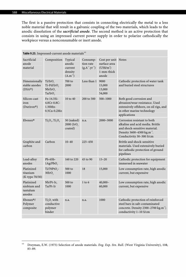
588 Miscellaneous Electrical Materials
The first is a passive protection that consists in connecting electrically the metal to a less noble material that will result in a galvanic coupling of the two materials, which leads to the anodic dissolution of the sacrificial anode. The second method is an active protection that consists in using an impressed current power supply in order to polarize cathodically the workpiece versus a nonconsumable or inert anode.
Table 9.23. Impressed-current anode materials165
Sacrificial anode material
Composition Typical anodic current density (A.m–2)
Consump-tion rate (g.A–1.yr–1)
Cost per unit surface area (US$/m2) 1-mm-thick anode
Notes
Dimensionally stable anodes (DSA®)
Ti/IrO2
Ti-Pd/IrO2
Nb/IrO2
Ta/IrO2
700 to 2000
Less than 1 9000 15,000 13,000 54,000
Cathodic protection of water tank and buried steel structures
Silicon-cast iron (Duriron®)
Fe-14.5Si-4.0Cr-0.8C-1.50Mn-0.5Cu-0.2Mo
10 to 40 200 to 500 500–1000 Both good corrosion and abrasion/wear resistance. Used extensively offshore, on oil rigs, and in other marine technology applications
Ebonex® Ti4O7, Ti5O9 50 (naked)2000 (IrO2 coated)
n.a. 2000–3000 Corrosion resistant to both alkaline and acid media. Brittle and shock-sensitive material. Density 3600–4300 kg.m–3. Conductivity 30–300 S/cm
Graphite and carbon
Carbon 10–40 225–450 Brittle and shock-sensitive materials. Used extensively buried for cathodic protection of ground pipelines
Lead-alloy anodes
Pb-6Sb-1Ag/PbO2
160 to 220 45 to 90 15–20 Cathodic protection for equipment immersed in seawater
Platinized titanium (K-type 70/30)
Ti/70PtOx-30IrO2
500 to 1000
18 15,000 Low consumption rate, high anodic current, but expensive
Platinized niobium and tantalum anodes
Nb/Pt-Ir, Ta/Pt-Ir
500 to 1000
1 to 6 40,000–60,000
Low consumption rate, high anodic current, but expensive
Ebonex®/ Polymer composite
Ti4O7 with
conductive polymer binder
n.a. n.a. 1000 Cathodic protection of reinforced steel bars in salt-contaminated concrete. Density 2300–2700 kg.m–3; conductivity 1–10 S/cm
165 Dreyman, E.W. (1973) Selection of anode materials. Eng. Exp. Stn. Bull. (West Virginia University), 110,
83–89.
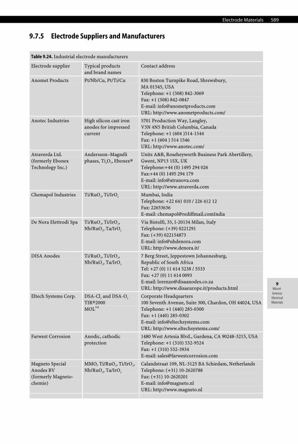
Electrode Materials 589
9 Miscel-laneous
Electrical Materials
9.7.5 Electrode Suppliers and Manufacturers
Table 9.24. (continued)
Electrode supplier Typical products and brand names
Contact address
Anomet Products Pt/Nb/Cu, Pt/Ti/Cu 830 Boston Turnpike Road, Shrewsbury, MA 01545, USA Telephone: +1 (508) 842-3069 Fax: +1 (508) 842-0847 E-mail: [email protected] URL: http://www.anometproducts.com/
Anotec Industries High silicon cast iron anodes for impressed current
5701 Production Way, Langley, V3N 4N5 British Columbia, Canada Telephone: +1 (604 )514-1544 Fax: +1 (604 ) 514 1546 URL: http://www.anotec.com/
Atraverda Ltd. (formerly Ebonex Technology Inc.)
Andersson–Magnéli phases, Ti4O7, Ebonex®
Units A&B, Roseheyworth Business Park Abertillery, Gwent, NP13 1SX, UK Telephone:+44 (0) 1495 294 026 Fax:+44 (0) 1495 294 179 E-mail: [email protected] URL: http://www.atraverda.com
Chemapol Industries Ti/RuO2, Ti/IrO2 Mumbai, India Telephone: +22 641 010 / 226 412 12 Fax: 22653636 E-mail: [email protected]
De Nora Elettrodi Spa Ti/RuO2, Ti/IrO2, Nb/RuO2, Ta/IrO2
Via Bistolfi, 35, I-20134 Milan, Italy Telephone: (+39) 0221291 Fax: (+39) 022154873 E-mail: [email protected] URL: http://www.denora.it/
DISA Anodes Ti/RuO2, Ti/IrO2, Nb/RuO2, Ta/IrO2
7 Berg Street, Jeppestown Johannesburg, Republic of South Africa Tel: +27 (0) 11 614 5238 / 5533 Fax: +27 (0) 11 614 0093 E-mail: [email protected] URL: http://www.disaeurope.it/products.html
Eltech Systems Corp. DSA-Cl2 and DSA-O2 TIR®2000 MOLTM
Corporate Headquarters 100 Seventh Avenue, Suite 300, Chardon, OH 44024, USA Telephone: +1 (440) 285-0300 Fax: +1 (440) 285-0302 E-mail: [email protected] URL: http://www.eltechsystems.com/
Farwest Corrosion Anodic, cathodic protection
1480 West Artesia Blvd., Gardena, CA 90248-3215, USA Telephone: +1 (310) 532-9524 Fax: +1 (310) 532-3934 E-mail: [email protected]
Magneto Special Anodes BV (formerly Magneto- chemie)
MMO, Ti/RuO2, Ti/IrO2, Nb/RuO2, Ta/IrO2
Calandstraat 109, NL-3125 BA Schiedam, Netherlands Telephone: (+31) 10-2620788 Fax: (+31) 10-2620201 E-mail: [email protected] URL: http://www.magneto.nl
Table 9.24. Industrial electrode manufacturers
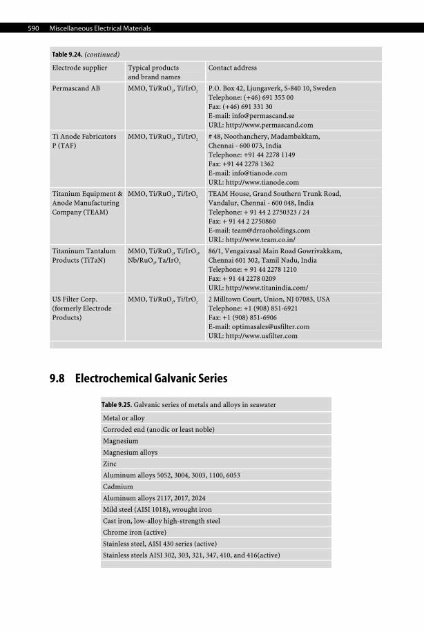
590 Miscellaneous Electrical Materials
Table 9.24. (continued)
Electrode supplier Typical products and brand names
Contact address
Permascand AB MMO, Ti/RuO2, Ti/IrO2 P.O. Box 42, Ljungaverk, S-840 10, Sweden Telephone: (+46) 691 355 00 Fax: (+46) 691 331 30 E-mail: [email protected] URL: http://www.permascand.com
Ti Anode Fabricators P (TAF)
MMO, Ti/RuO2, Ti/IrO2 # 48, Noothanchery, Madambakkam, Chennai - 600 073, India Telephone: +91 44 2278 1149 Fax: +91 44 2278 1362 E-mail: [email protected] URL: http://www.tianode.com
Titanium Equipment & Anode Manufacturing Company (TEAM)
MMO, Ti/RuO2, Ti/IrO2 TEAM House, Grand Southern Trunk Road, Vandalur, Chennai - 600 048, India Telephone: + 91 44 2 2750323 / 24 Fax: + 91 44 2 2750860 E-mail: [email protected] URL: http://www.team.co.in/
Titaninum Tantalum Products (TiTaN)
MMO, Ti/RuO2, Ti/IrO2, Nb/RuO2, Ta/IrO2
86/1, Vengaivasal Main Road Gowrivakkam, Chennai 601 302, Tamil Nadu, India Telephone: + 91 44 2278 1210 Fax: + 91 44 2278 0209 URL: http://www.titanindia.com/
US Filter Corp. (formerly Electrode Products)
MMO, Ti/RuO2, Ti/IrO2 2 Milltown Court, Union, NJ 07083, USA Telephone: +1 (908) 851-6921 Fax: +1 (908) 851-6906 E-mail: [email protected] URL: http://www.usfilter.com
9.8 Electrochemical Galvanic Series
Table 9.25. (continued)
Metal or alloy
Corroded end (anodic or least noble)
Magnesium
Magnesium alloys
Zinc
Aluminum alloys 5052, 3004, 3003, 1100, 6053
Cadmium
Aluminum alloys 2117, 2017, 2024
Mild steel (AISI 1018), wrought iron
Cast iron, low-alloy high-strength steel
Chrome iron (active)
Stainless steel, AISI 430 series (active)
Stainless steels AISI 302, 303, 321, 347, 410, and 416(active)
Table 9.25. Galvanic series of metals and alloys in seawater
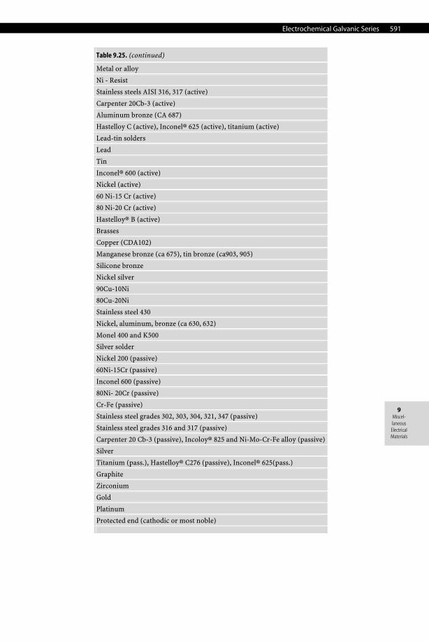
Electrochemical Galvanic Series 591
9 Miscel-laneous
Electrical Materials
Table 9.25. (continued)
Metal or alloy
Ni - Resist
Stainless steels AISI 316, 317 (active)
Carpenter 20Cb-3 (active)
Aluminum bronze (CA 687)
Hastelloy C (active), Inconel® 625 (active), titanium (active)
Lead-tin solders
Lead
Tin
Inconel® 600 (active)
Nickel (active)
60 Ni-15 Cr (active)
80 Ni-20 Cr (active)
Hastelloy® B (active)
Brasses
Copper (CDA102)
Manganese bronze (ca 675), tin bronze (ca903, 905)
Silicone bronze
Nickel silver
90Cu-10Ni
80Cu-20Ni
Stainless steel 430
Nickel, aluminum, bronze (ca 630, 632)
Monel 400 and K500
Silver solder
Nickel 200 (passive)
60Ni-15Cr (passive)
Inconel 600 (passive)
80Ni- 20Cr (passive)
Cr-Fe (passive)
Stainless steel grades 302, 303, 304, 321, 347 (passive)
Stainless steel grades 316 and 317 (passive)
Carpenter 20 Cb-3 (passive), Incoloy® 825 and Ni-Mo-Cr-Fe alloy (passive)
Silver
Titanium (pass.), Hastelloy® C276 (passive), Inconel® 625(pass.)
Graphite
Zirconium
Gold
Platinum
Protected end (cathodic or most noble)

http://www.springer.com/978-1-84628-668-1