mirage & matrix - mmopa to service manual mirage... · as with all other high ... asking...
TRANSCRIPT
Return to Service Manual for
PA46 Aircraft
Mirage & Matrix

PROVIDED AS A MEMBER BENEFIT FOR MMOPA
CONTRIBUTORS
Mary Bryant - Malibu
Ron Cox- Mirage
John Mariani- JetProp
Dick Rochfort- Meridian
MECHANICAL REVIEW
Kevin Mead
ORGANIZED AND EDITED
Jeff Schweitzer
Richard Geist
COPYRIGHT © 2009, 2011
MALIBU/MIRAGE OWNERS AND PILOTS ASSICIATION
P.O. Box 1288 Green Valley, AZ 85622
Reproduction prohibited without permission.

Overview
Proper maintenance is essential to safety in aviation. As with all other high-performance aircraft,
the PA46 requires close scrutiny and regular maintenance to ensure that all systems are
functioning properly. At a minimum, the aircraft undergoes extensive disassembly during the
annual inspection. Mid-year events or unpleasant discoveries during routine 100 hour
inspections often call for substantial unscheduled maintenance between annuals. No matter the
timing or cause, the first flight after extensive maintenance requires an extra dose of care and
caution.
The combination of the airplane’s incredible complexity and the inherent imperfections of people
working on them means that maintenance itself can have the ironic effect of causing systems
failures. The more extensive the maintenance, the greater is the chance for a potential problem.
The primary means of identifying any issues and correcting them before one or more become
catastrophic is to follow carefully an extensive and well-structured checklist.1
A good return-to-service post-maintenance checklist covers a comprehensive pre-flight and a
structured first check-flight to prove that all systems are functioning properly. Anticipating the
unforeseen, the first flight is conducted with certain precautions not routinely incorporated into
normal flight operations. An example is staying close to the airport, which of course is not
practical for cross-country flying but essential to the safety of an initial check-flight.
Background and History
In 1991 the first edition of our MMOPA magazine included the first of several installments on
preparing the plane for return to service after a major maintenance event.
The five part series was written by Andrew Cindric, a former Piper Director of the Aircraft
Completion Center in Vero Beach.
His series was converted into booklet form and distributed to all members for easy use with the
plane at the point of service. Andrew’s introduction is still applicable today:
Return-to-Service Test Flight
Is it really necessary? Is it a legal requirement? Why should I do it? Who should
do it? How long does it take?
We will take a look at the answers to these questions and many more in the
following discussion. I personally believe a Return-to-Service Test Fight should
be performed any time engine or control surface repairs and adjustments were
made, an aircraft is coming out of an annual or 100 hour inspection, after major
maintenance was performed, etc.
1 The pilot-in-command is responsible for the safe and proper operation of his/her aircraft and it is the responsibility
of the pilot-in-command to operate that aircraft in compliance with that aircraft’s Pilot’s Operating Handbook and
other official manuals and directives.

Legally, it depends on how the mechanic or inspector interprets the regulations.
One shop may indicate a test flight is necessary, another may say don't worry
about it. "Why should the answer to this be any different than most other rules
regarding aviation?"
The reason a test flight should be performed is to prove that everything is
operating the way it was intended to operate. If it initially doesn't, then you can
find the problem during a test flight where you the pilot and maybe an assistant
are the only ones aboard the aircraft. Some of the discrepancies 1 have come
across over the years on the first flight after maintenance, I sure would not have
wanted to encounter on a dark, rainy night with the weather near minimums.
Andrew’s narrative style manual is no longer in print but the original articles are viewable on the
MMOPA web site.
With the addition of new PA46 models, engines and techniques it seems reasonable to update
this valuable manual for all members. The Board of Directors commissioned this update by
asking instructors and a mechanic experienced in each model to write a Return to Service manual
specific to a model and in a format that can easily be used in the plane. Because of the wide
variety of avionics and aftermarket products, only the standard systems usually found in the
PA46 will are covered.
This manual is provided as a MMOPA member benefit for the exclusive use by its members. It is
copyrighted and may not be copied or reproduced without permission.
General Principles
The time to discover a problem resulting from a significant maintenance event and repairs or
modifications is before carrying passengers or in hard instrument conditions.
The Test Flight should be performed after the following events:
Annual Inspection to prove airplane airworthiness and systems function.
Extensive airframe repairs or alterations to prove basic airworthiness.
Extensive engine repairs or alterations (such as engine replacement) to prove proper
functioning.
When airplane has not been flown for an extended period of time.
Extensive avionics alterations or upgrades to prove proper functioning and interfaces
with the autopilot, and to prove other systems have not been affected.
And potentially:
Prior to annual inspection in order to fine-tune the squawk list.
Prior to purchase.
Common sense dictates that no matter what airplane is being flown, certain essentials must be
addressed prior to the first post-maintenance check-flight.

Review and discuss with the mechanic all the maintenance that was completed, and use that as
an initial guide to focus early attention for the first flight.
Pay attention to any parts that were replaced in addition to normal checklist items.
Consider taking a good look under the cowling and any access panels before taking the
aircraft out of the shop.
Test as many systems as possible on the ground before lifting off. Test the autopilot, but
also get a good feel of the plane by hand-flying a portion of the test flight.
This is a good time to check infrequently-used or rarely-tested systems like emergency
gear extension, stall warning and anti-icing, for example.
Fly multiple approaches to test avionics in multiple scenarios, and to ensure the integrity
of the navigation equipment at the most critical moments of a flight.
Following major maintenance, the aircraft preflight inspection should take about one hour.
Do not rush through this process. As has been found whether air-racing or just completing
a normal flight, the event is usually “won” on the ground and lost in the air. Invest the
necessary time up-front to have a safe and uneventful return to service. Use the Piper Event
Checklists to help conduct the inspection in an organized fashion so that nothing is missed.
These checklists are available from any Piper dealer. Some items on the checklists require
tools, but remember this is a pilot inspection, not an annual inspection: do not use tools on
the expanded walk-around except for a bright flashlight, notebook and pen. Document all
items and functions that do not reflect a normal condition.
Position the aircraft to an area suitable to a comfortable inspection, with the expectation of lying
prone on the ground for some time to look into the wheel wells and nose gear bay. If
inexperienced, bring along someone with the proper experience to help. The most common
problems and issues are highlighted here, but everything must be checked for normal condition
and function. Perform the preflight inspection per POH procedures.
If the airframe and/or engine have undergone extensive repairs or alterations, it would be
desirable to perform the preflight with a knowledgeable representative of the shop that
performed the work. The same is true for extensive avionics work or upgrades. A
knowledgeable representative of the shop that performed the work should go through an avionics
cockpit check, explain any installation-unique features and review all the interfaces with the
autopilot. Note that due to previously-installed avionics many of these avionics alterations or
upgrades have features that are unique to the airplane being tested. These features have to be
clearly understood by the test pilot before an effective Test Flight can be conducted.
A responsible and knowledgeable representative of the shop that performed the work must also
be ready and willing to ride along on the Test Flight, if so requested by the test pilot. This is a
non-negotiable condition and should be made clear to the shop before any work is performed. If
the shop refuses to agree to these terms, find another shop.
Pilot Qualifications
The pilot performing the Test Flight has to be well qualified in the operation of the airplane and
all of its systems. A low-time pilot, or a pilot just qualified in the airplane, should not be
performing the Test Flight (no time-builders allowed) without a competent instructor on board.
No passengers allowed. No flight training should be conducted during the Test Flight. At the
most, a qualified assistant (such as a mechanic or avionics technician) can be carried. If you do
not feel qualified to perform the Test Flight, seek assistance.
A test pilot should be prepared for the unexpected and, equally important, should have
confidence in his own abilities to deal with emergencies. The test pilot should also be inquisitive
as to what was done to the airplane, and by whom. Trust, but verify. Remember, reasonable
paranoia is a good attribute for a test pilot.
Equipment on Board
The equipment to be carried is sometimes determined by the nature of the systems to be checked,
for example a propeller strobe to measure accurate RPM. Sometimes no specialized equipment
needs to be carried for the Test Flight. However, the following basic equipment, at a minimum,
should be carried at all times:
A note pad and a pen (to write down any discrepancies during the Test Flight).
A pocket multi-tool such as a Leatherman®, or equivalent, but always remember you are
not a mechanic.
A portable VHF transceiver (with a charged battery).
A Halon (1211 or 1211-1301 blend) fire extinguisher.
Flight Area and Environmental Conditions
Conduct the Test Flight in good day VFR only, and remain close to the airport, straying no more
than 50 NM. Make no exception to this rule. An airport equipped with good emergency services
(firefighting and first aid) would be highly desirable. Also, depending on the importance of the
items being checked (i.e. basic airworthiness of the airframe and engine), it would be desirable to
remain closer (within 10 NM or within easy gliding distance) of the departing airport.
Safety
While obvious, safety must be the number one priority of any Test Flight. The test pilot should
never be rushed or under pressure to complete the flight. If any condition arises that puts the
safe outcome of the Test Flight in doubt, the flight must be terminated immediately. Be prepared
to declare an emergency even if suspecting the conditions require such action.
Checklist Structure
Each model of the PA46 has a unique configuration based on engine type and year of production.
Reflecting that diversity, there are several versions of this manual. Each devoted to one model:

the Meridian, JetProp, Mirage/Matrix or Malibu. The Matrix is combined with the Mirage, with
the expectation that Matrix pilots will simply ignore any checklist items relating to
pressurization. Each member will receive the section applicable to his/her model. The return-to-
service checklist for each variation of the PA46 is unique, even if much of the checklist is
common to all.
Liability Limitation
This checklist is not provided from, endorsed by, affiliated with, nor supported by the New Piper
Aircraft, Inc., Lycoming Engines, Continental, Pratt and Whitney, JetProp or any other parts or
equipment vendor in any way. All copyrights remain the property of their respective owners. The
procedures contained within are necessarily based upon generic flight operations and intended to
supplement compliance with all operating manuals for the aircraft and systems described therein.
These procedures are not always accurate in all situations. MMOPA (including but not limited to
the authors contributing to the checklist or editors of the checklists) assumes no liability for any
incorrect information. The purpose of the checklist is not to claim ownership of any content
herein, rather, to show flight operations and performance of the PA46 based on available public
information.
Material in the checklist may include technical inaccuracies or typographical errors. Changes
may be periodically incorporated into this material. MMOPA may make improvements and/or
changes to the content described in these materials at any time without notice.
THE CHECKLIST MATERIALS ARE PROVIDED "AS IS" WITHOUT WARRANTY OF ANY
KIND, EITHER EXPRESSED OR IMPLIED, INCLUDING, BUT NOT LIMITED TO, THE IMPLIED
WARRANTIES OF MERCHANTABILITY OR FITNESS FOR A PARTICULAR PURPOSE.
IN NO EVENT SHALL MMOPA, (including but not limited to the authors contributing to the checklist
or editors of the checklists,) BE LIABLE FOR ANY DAMAGES WHATSOEVER, INCLUDING
SPECIAL, INDIRECT, CONSEQUENTIAL OR INCIDENTAL DAMAGES OR DAMAGES FOR
LOSS OF PROFITS, REVENUE, USE, OR DATA WHETHER BROUGHT IN CONTRACT OR
TORT, ARISING OUT OF OR CONNECTED WITH ANY OF THE CHECKLIST OR THE USE,
RELIANCE UPON OR PERFORMANCE OF ANY MATERIAL CONTAINED IN THE
CHECKLISTS.
THERE IS NO WARRANTY, REPRESENTATION, OR CONDITION OF ANY KIND; AND ANY
WARRANTY, EXPRESS OR IMPLIED, IS EXCLUDED AND DISCLAIMED, INCLUDING THE
IMPLIED WARRANTIES OF MERCHANTABILITY AND OF FITNESS FOR A PARTICULAR
PURPOSE.
THE PILOT IN COMMAND IS RESPONSIBLE FOR THE SAFE AND PROPER
OPERATION OF HIS/HER AIRCRAFT AND IT IS THE RESPONSIBILITY OF THE PILOT IN
COMMAND TO OPERATE THAT AIRCRAFT IN COMPLIANCE WITH THAT AIRCRAFT'S
PILOT'S OPERATING HANDBOOK AND OTHER OFFICIAL MANUALS AND DIRECTIVES.

ANNOTATED CHECKLIST

Preflight
Since the PA-46-350P has been in production continuously from 1989 to the present there have
been several modifications to the airframe, avionics, and components. Each Mirage therefore
will be a little different than other production units, but all have more in common than
differences. Avionics, autopilots, instruments, switches, interiors props, and cowlings are the
greatest changes and differ mostly by year of manufacturing. Items specific to the Mirage or
Matrix are noted.
Aircraft and Maintenance Documents
Review with the shop all the maintenance requested on the squawk list.
Query mechanic as to status and results of each item, including: incoming squawks
and new items mechanic may have found; intermittent items or UTD (unable to
determine); results of his engine ground check for operation and leaks; results of oil
analysis and type of oil used to replenish the engine; and remember to get the keys
to the aircraft.
Aircraft Inspector (IA) signs off in the maintenance logs.
Maintenance logs must be reviewed for completion of work. Several insurance
companies have denied claims because the aircraft was not properly returned to
service with appropriate entries entered into the maintenance log books and
properly authenticated by an IA. The logs do not have to be in the aircraft.
Verify that all Airworthiness Directives (AD) are complied with.
Verify the revision level of the POH.
Call any Piper Service Center Parts Department. The representative will need the
“VB” number in the lower right corner of the page, and the serial number of the
aircraft. Piper will provide up to 3 revision levels free of charge. If the book is 4 or
more revisions out of date, a new book will need to be purchased. To ensure the
timeliest response, contact Piper in writing and inform Piper the request comes from
the aircraft owner. Note that the FAA database on ownership transfers can lag 90
days or more.
Verify that the current weight and balance data sheet is in the aircraft.
Verify that airworthiness certificate (with correct information) is in the aircraft.
On board the aircraft must be the pilot operating handbook (POH). It contains three
required documents required by the FAA: a) Weight and balance data, b) aircraft
limitations, and c) performance data. Also the aircraft registration and airworthiness
certificate must be prominently displayed on board, normally on the aft bulkhead.
Check for complete and correct placards on the aircraft using the up-to-date POH.
A list of required placards is found in Section 2, “Limitations.”
Check weather and file flight plan for a local flight, if the early preflight to this point
has not precluded continuing with the flight.
Checkouts should be done in VFR conditions or conditions providing adequate
weather should unanticipated equipment failures be experienced. Minimal
personnel should be on board. One doesn’t want to be with her grandchildren over
the Rockies en-route home when unresolved maintenance issues are discovered.
However, a knowledgeable second person can be helpful during later portions of the
checkout when the pilot’s attention needs to be focused on flying the aircraft.
Initial Observations
Observe the general condition of the aircraft as you approach. Verify the struts are
level.
Approach the aircraft with all senses keenly operating. Sight, smell, touch, feel, and
hearing must be used on the pre-flight. A polished, clean, and level aircraft is a
good start to a preflight inspection. Make sure nothing is hanging, dripping, or
inappropriately attached, unattached or missing.
Check fuel visually and note level. Secure the caps.
Verify that the correct tires are installed.
Check tire pressure with a pressure gauge.
Use a gauge with the correct pressure range. Bring a small right-angle Phillips
screw driver to remove the main wheel fairings that cover the valve stems. (Main
tire is 600x6 8 ply, pressure is 55 lbs; nose tire is 500x5 6 ply, pressure is 50 lbs).
Verify the airplane has been washed after the maintenance was complete.
Initial Cockpit and Interior Check
Note: do not test the windshield heat and stall warning heat on the ground, as it can cause
overheat damage to these components.

Enter cockpit and verify that magnetos are off.
Confirm gear selector down.
Fuel tank selector in either left or right position.
All switches off as expected.
Pay particular attention to pressurization switches, knobs, fuel boost switch,
day/night dimmer switch, HSI slaving selector, fans, blowers and other high draw
items. Some of the switch positions may have been changed by the mechanic and
the battery may be low from repeated activation of electrical items during
maintenance without use of auxiliary ground power.
Check that all circuit breakers are in.
If any are out, verify why.
Check Ground Clearance Switch.
With Battery Master OFF and no power on the airplane, turn the Ground Clearance
ON: one Com radio should come on. Perform a radio check with an appropriate
ground facility. Turn Ground Clearance switch OFF after the radio check.
Push in static drain.
Do not cover the drain when pushing in the valve. Some instructors recommend that
pilots avoid draining static system unless clearly indicated need to do so. Instead,
verify that the static drain is secure. Draining the system introduces moisture into
an otherwise closed system. If the drain is not absolutely secure, the aircraft will
experience both pressurization and instrumentation anomalies.
Check elevator is free and correct.
Check for free and correct movement with full travel of control wheel. The elevator
should deflect trailing-edge up when the control wheel is moved aft, and trailing-
edge down when the control wheel is moved forward.
Pull control wheel full aft to the stop and verify that it moves full forward under the
force of the spring when released.
Check elevator trim.
Move elevator trim wheel manually through its full travel (nose-up and nose-down)
and verify indicator accuracy and no binding. The trim tab should deflect trailing-
edge up when the trim wheel is moved nose-down, and trailing-edge down when
the trim wheel is moved nose-up. Have someone confirm outside.
Check ailerons are free and correct.
Check for free and correct movement with full travel of control wheel. Left turn:
left aileron up; right turn: right aileron up. Check ailerons neutral with control
wheel level. Check that both control wheels line up with each other. Check that
fixed trim tab on right aileron is reasonably faired-in with top surface of aileron (an
excessively bent tab likely indicates an out-of-rig condition).
Check power lever.
Check for freedom of movement and operation of friction lock, and then move to
idle position.
Battery switch on.
Check voltage to ensure battery charged. Look for a minimum of 22 volts for start.
Charge or arrange power assisted start, if appropriate. Verify power to all
equipment.
Check for fuel quantity and verify fuel indicators consistent with visual check.
Test stall warning device test switch for electrical continuity.
Push the stall test button for an audible sound. This confirms there is electrical
continuity in the unit. All Mirage aircraft have the Safe Flight computerized stall
warning indicators on the left wing. Because of the design sensitivity of this left
detector a “no touch” policy has to exist for all Mirage aircraft and their lift
detectors.
Check all internal lights for operation.
Determine annunciators illuminated as expected, check remaining annunciators for
illumination using test switch, and verify 3 green gear lights.
Place flap handle in full down position 36 degrees.
Lower the flaps to the full down or 36 degree position for the walk around
inspection outside. Confirm that the flap indicator shows the appropriate position on
its gauge.
Check alternate air door for full and unobstructed operation.

Ensure moves properly, noting proper resistance and confirm sound of opening and
closing. Verify shut completely to avoid ingesting debris when start engine. Avoid
opening when engine running on the ground.
With assistance from someone outside, verify all lights operate.
Check the function of all exterior lights (position, strobe, navigation,
landing, taxi, pulse and ice).
Check stall vane function
Vane function: press the stall warning test button while someone observes the vane.
The vane should move full deflection when the test button is pushed.
Vane heating: When your Mirage or Matrix came from the factory its stall vane heater
was wired through the left main gear door switch. However, after compliance with Piper
AD 2008-26-11, which requires installation of the stall warning heat control modification
kit, the high stall heat will instead be activated by actuation of the squat switch. If AD
2008-26-11 has been accomplished, test stall heat on the ground using the following
procedure. With the stall heat switch in the cabin “on”, have someone actuate the squat
switch, located on the left main gear scissor. Have a second person feel the mounting
base of the stall transducer. It should get hot almost immediately, after which the squat
switch should be released. Do not touch the stall transducer tab.
Battery, radio master and magnetos off and secured.
Check side or storm window for cracks and security.
Check oxygen system (Matrix only) by plugging in mask, pulling the oxygen flow
valve open and observing flow by seeing the black ball rise in the column when held
vertically. Record amount of oxygen in the tank before and after the flight as a decrease
suggests a leak.
Interior checks of seats, belts, cabinets, emergency exit, and cargo netting for security
and cracks.
Check hydraulic fluid level in area aft of baggage storage. Remove panel or use sight
gauge. Add fluid (MIL-H-5606) if necessary.
Do not overfill this reservoir or serious damage can result.
Check all of the seat backs for integrity and cracks beneath the carpeted backs.
Check the clear plastic document pouch for the presence of the correct airworthiness
certificate and registration.

Remove old and outdated documents.
Verify that the spring loaded seat back release latches are operating normally and not
damaged or binding.
Ensure that required equipment is available in the airplane.
This list would include at least the following:
microphone or headset
self-calibrating precision strobe tachometer
screw driver
fire extinguisher
pencil or pen and paper to record results
carbon monoxide detector
handheld Nav/Com
fuel strainer
Main Cabin Door (MCD)
Check main cabin door pressure seal.
The main cabin door (MCD) should be checked for pressure seal abrasions and
punctures, particularly at the door locking pin wells. Sometimes the pin damage
even extends to the fuselage skin in front of the pin wells. While this is indeed ugly,
paint damage does not affect performance.
Inspect the fuselage below and aft of the MCD for skin and paint damage from baggage
transfer.
The top half of the MCD may be misaligned at the seam between the door and
fuselage, tight on the forward side and wide on the aft. This is typical on older
aircraft.
Visually inspect the cables for broken strands and/or loose hardware. Check the cables
for even tension fore and aft.
Proper and equal tension will ensure that even weight is applied when the steps are
used.
Inspect the hinge of the lower half of the MCD for evidence of corrosion.
This hinge area is exposed to a lot of water. Almost any airplane three years older
or more will experience some corrosion here.
Left Wing
Verify condition of flaps.
Upside-down bolt in position and secured.
No cracks on forward flap bell crank.
Flap idler arm secured.
Flap rollers free and no excessive play or wear.
Flap tracks clear of debris. Light coating of water soluble grease.
No dents or cracks in the flaps.
Check presence and condition of Mylar chafe tape under the wing overhang.
Recommend application of chafe tape of top side of flaps.
Check for missing static wicks.
Verify that the two stall strips on each wing, located mid-wing and near the wing root,
are present and secured.
Inspect the aileron.
All rollers and cable routings on the aft side of the wing should be free and correct
to the aileron sector pulley. Stops on the pulley must be set for the aileron limits of
travel. Counterweights on the leading edge of the aileron must be secured. The
aileron should move freely throughout its range of motion.
Check aileron cables for routing, corrosion, and kinking.
Check aileron guides for positioning and security.
Sector pulley secured.
Limit bolts secured.
Free in all range of travel.
Aileron counterweights installed.
Confirm that wing tip is absent any hanger rash.
Check all surfaces for loose rivets.
Strobe and navigation lights secured, with no corrosion around light mountings.
Remove Pitot cover.
Verify that the main span “I” beam upper and lower surface is free of cracks or
deformation.

Confirm fuel vent open and clear.
Ensure that the NACA fuel vent is clear and open. Do not put any object in the fuel
vent that can damage the rubber portion of the fuel relief valve.
Check carefully the dielectric paint (the flat black paint that borders the boot).
Check boot integrity, looking for pin holes or tears.
During flight a boot inflation test should be conducted to see if the boots are
inflating properly and the appropriate lights showing the boot cycle should be on
for the designated time. The only problem with this test is that the pilot cannot see
all the positions of the boots in flight. While on the ground and at an RPM of 2,000
the pilot with the assistance of an outside observer should conduct an inflation cycle
and have him/her observe each of the boot pads for proper inflation. The 2000 RPM
engine speed is required in order to develop enough vacuum pressure for the test.
Obviously extreme care must be taken to ensure the observer remains clear of the
propeller. If this test is conducted, when complete, shut down and continue
preflight.
Inspect bottom of the wing for fuel leaks.
Check the landing gear doors for security and proper angle 10 degrees out.
The left main landing gear door should be firmly attached and angled out
approximately 10 degrees from the gear strut. This will assist in pulling the main
gear out during emergency gear extension operations.
Verify that the squat switch (left gear only) is clean, and all electrical leads attached.
Confirm that struts are inflated 3.5 inches with full fuel.
Verify that there is no excessive play or wear on landing gear torque links.
The scissor links should have no noticeable play.
Check tire condition.
Look for any excessive wear, and no chord should be showing. Main tire pressure is
55 lbs, nose tire pressure is 50 lbs.
Check brake pad thickness. Minimum allowable thickness is 0.10” or about the
thickness of two stacked pennies.
Verify that the brake line security bolt head is facing away from the tire.
Confirm that no brake lines leaking.
Verify that the gear actuator attachment point at rod end safe tied.
Ensure that the wheel well is clean of debris.
Drain fuel.
Note that draining the fuel at the collector tank can create problems with a stuck
drain. Do not twist the drain valve when draining fuel. This will allow the valve to
stick open. While draining the fuel look at the bottom of the airplane; any oil,
exhaust, or grease stains should be investigated at this time especially if the stains
appear fresh from the last flight or inspection.
Engine Cowling and Nose Section
Inspect the front baggage area.
Confirm that the handle and lock are secured.
Confirm that the door ajar is off on annunciator panel.
Check brake fluid level.
Check condition of instrument filter for dirt.
Check security of cross-over bleed air pipes.
Check that the battery drain orifice is open and unobstructed.
Inspect the exhaust pipe.
Verify that the oil breather tube is attached to exhaust pipe (left exhaust only).
Confirm no excessive play on the exhaust pipe. This is a no fly condition due to
the potential fire hazard.
Check under aircraft for signs of excessive oil usage or leaks.
Ensure that all of the cowling fasteners are present and flush with the cowling.
Inspect the nose gear doors.
Check the piano hinge for security.
Check for cracks or bend marks on the doors (indicating sequence valve
failure).
Confirm there are no rub marks on the doors.
Verify that Mylar chafe tape is attached to lower edge of RH nosegear door.
Inspect the nose wheel.
The nose gear should be tight with little as .025 play in the steering arm rollers fore
and aft when moving the nose gear strut. Check for excessive turn limits of greater
than 30 degrees by checking the turn limits stops on the left and right portion of the
steering arm. Ensure that the locking pin on the nose wheel is in place.
Check tire for cuts or excessive wear. No chord should be showing. Inflate to 50
PSI.
Confirm the stem valve is in good condition and properly positioned.
Strut should be inflated to a minimum of 1.5 inches with fuel tanks fuel.
Confirm that the torque link is secure, with no noticeable play.
Place your foot on the top of the nose wheel tire and try to push the tire
rearward. There should be no play in the strut.
Check the gear-assist spring for security. Ensure that the safety wire is installed
through the actuator attach bolt.
Look up into the nose wheel bay.
Lie on your back to get a good look into the engine well (good reason to be
wearing old clothes for these inspections.
Check the nose steering bar for security and roller-to-bell crank clearance.
Check the position of the gear door sequence valve. You should see no bending
on plunger.
Check for oil leaks on engine bottom pan and landing gear actuators.
Check control cables for throttle, prop, mixture, and alternate air box for
security. Ensure there are no bends in the cables.
Inspect the cowling.
Check for cracks.
Check security of the nose bowl.
Ensure that all of the cowling fasteners are present and flush with the cowling.
Check security of air box.
Check oil level and condition.
Check the quantity to ensure a 9 quarts minimum (12 full).
Check the condition of the oil. Black oil after eight to nine hours of usage
indicates excessive carbon on the pistons, or oil rings leaking.
Check for oil leaks on the bottom of the engine.
Inspect the propeller.
There are three basic type of props approved for the Mirage a two bladed
aluminum, the German MT wood core laminated four bladed, and the three bladed

Kevlar composite. What matters on any prop is the amount of thickness left in the
chord line of the prop. This determines the serviceability of the prop. Corrosion of
any type in and around the internal components of the prop is grounds for declaring
the entire prop hub unserviceable, this is usually the result of water seeping into the
hub and not properly servicing the prop at recommended intervals. Any detected
play of the blades near the hub attachment point is also grounds for determining the
prop to be unserviceable.
Two-blade metal
The two bladed prop should be inspected for nicks and gouges. This prop allows for
some filing to dress the props of any nicks picked up by small stones on the
taxiway.
Check for cracks, nicks, and dings on the blades.
Check the back spinner for cracks.
Check the prop hub for cracks, dents, or bulges.
Inspect prop de-ice pads for security.
Three- and four-blade
The four bladed MT and three bladed Hartzell prop cannot be externally filed like
the two bladed aluminum prop and only composite material build up can be applied
to eradicate any nicks in the prop.
Check for delaminating props.
Check for nicks or punctures of the protective metal guard (remember that there
is no filing of composite props).
Check prop spinner and back plate for cracks.
Inspect prop de-ice pads for security.
Check lower cowl exhaust tunnels for security and clearance.
Test the alternator belt to ensure the belt is tight and verify that the #1 alternator is
attached securely.
Check the heat muff.
The heat muff on the lower right cowling should be checked for security. No visible
oil or any other fluids should be observed leaking out of the engine compartment of
the aircraft.
Right Wing
Drain fuel.
Move directly from checking the heat muff to inspect and drain the right fuel sump.
Repeat inspection as with Left Wing.
Fuselage Right Side
Check emergency exit for security.
No corrosion should be observed around the attachment point of the window. The
window should have been removed and replaced in accordance with procedures
outlined in the aircraft maintenance manual.
Check that the relief tube is operational (using water).
Confirm that the drain vents on bottom of fuselage are clear.
Verify that the A/C drain bevel is facing aft.
Look for oil, hydraulic fluid on belly of aircraft.
Look for corrosion where the alternate static ports and outflow valve pads are located
under aircraft.
Check the inspection port for the rudder and elevator for security.
Check static ports for water contamination.
Check the upper empennage for antenna security.
Horizontal Stabilizer
Check attachment bolts for security.
Also note that forward of the elevator the forty-five degree rivet line should have no
working rivets.
Move the stabilizer up and down to feel for any movement (none should be felt).
Check boots for attachment and holes.
Check elevator attachment bolts for security and corrosion.
Tail Cone
Check trim tubes for security. No fore or aft play.
Check drain hole in tail cone is clear.
Check rivets on top of horizontal stabilizer.
Rudder
Move the ruder slowly to make sure it is securely attached.
Check attachment bolts visually for security.
Check for cracks or dents.
Fuselage Left Side
Check static ports for water contamination.
Check A/C condenser screens for security
Inspect oxygen access door (Matrix only), insure the filling cap is secure and pressure
at 1850 psi. Record pressure.
Enter airplane and secure door.
Verify locked with four greens and a secure and locked handle.
Pilot and Copilot Seats
Check all functions just as with the passenger seats.
Check seats for positive engagement of seat latch, and for installed stops at each seat
track.
Check the height adjustment, the fore/aft slide adjustment and lumbar support function.
Verify proper seat belt function.

Make sure that the seat belts on all seats are installed correctly and not bound by the
seat track or seat position.
Check lap belts and shoulder harnesses for fraying. Check shoulder harnesses for
proper operation of inertia reels (should lock when tugged).

FIRST TEST FLIGHT
Before Engine Start
Check the security and function of each and every switch, left to right around the
cockpit.
Turn the night lights up and verify that all lights and dimmer knobs are working,
particularly the standby instrument internal lights.
Press the annunciator panel test button and observe all of the pretty lights.
Verify the primary static air source is selected.
Complete all other items listed in the POH checklist.
Engine Start
Start the engine using the approved checklist in the POH.
Before completing the check list, turn on the 5 important switches. These switches
are master, 2 mags, and 2 alternators. Then complete the checklist as indicated.
This approach will help avoid trying to start the aircraft with the mags off as can
easily happen if distracted while completing the checklist per the POH.
Note Hobbs time, local time and fuel on board.
Test autopilot per POH.
Elevator trim test.
Check manual electric operation for full travel in both directions; check each half of
split-switch; check trim disconnect; check priority of Pilot’s trim over Copilot’s
trim (if installed); pull pitch trim C/B and verify electric trim is disabled; reset pitch
trim C/B and set trim for Takeoff.
Yaw damper off. (Mirage only)
Verify rudder trim is neutral and make sure Yaw Damper is OFF before taxiing.
Test brakes.
Test brakes before taxiing.

Navigation and anti-collision lights on or off, as required.
Check operation of cockpit lights.
Verify proper operation of heating and air conditioning.
Check operation (with OAT <20 degrees C). Verify AUX HEAT does not operate
with VENT/DEFOG fan OFF. Check operation of Air Conditioning (HI and LO
fan).
After Engine Start
Conduct the post-start checklist per the POH, and note any discrepancies.
Verify all data subscriptions are up to date and that all avionics boot up correctly.
Copy and set the clearance into the panel in the usual way.
Note any discrepancies as data are entered. An IFR clearance will be needed for the
portion of the checks done above 17,500 feet, but that does not mean flying in IMC.
Fly in VMC on the first flight test; some low altitude checks require VMC. To
avoid delays, take off VFR and pickup the IFR clearance at a filed time, altitude and
fix (a VFR/IFR flight plan).
Check the flight control systems for free and correct operation.
This is so basic but is perhaps one of the more important checks made during any
flight preparation but especially return to service. Completion of this check cannot
be overemphasized. Aircraft should track straight ahead with rudder properly
trimmed. No excessive drifting should be observed.
Check the free and normal movement of the power lever.
Check normal operations of the autopilot.
This will include a check of all lights and disconnects, and a full check per the A/P
supplement.

Taxi
Verify braking action on all four pedals if a co-pilot is on board.
Check for play in the rudder steering mechanism. There should be none. Check the
copilot side as well.
Note the free and correct movement of all of the instruments including the compass.
Pay close attention to the HSI, turn and bank, and attitude indicator. Verify the
presence and correctness of the compass card.
Check the ELT. Plan to run the ELT for a few cycles while monitoring 121.5, but only
during the first 5 minutes after the hour.
Press and hold each Pitot-Static System Condensate Drain for a second or two, and
observe that there are no “nervous” pitot static instruments.
Flaps to take-off position.
Verify COM and NAV frequencies are set properly.
Verify flight instruments.
ASI (zero reading) / ADI (erect) / ALT (indicates within 40 feet of field elevation
when set to current altimeter setting) / TC (check when turning and no red flag) /
HSI and DG (check for proper indication on known heading; reset DG as required) /
VSI (zero reading).
Check magnetic compass.
Check for proper indication on known heading. Check agreement with HSI within
10 degrees (with air conditioning and re-circulating blowers OFF).
Run Up
Listen for any new, changed or unusual sounds.
Investigate anything that seems out of the ordinary. Remember that the aircraft just
underwent major maintenance.
Conduct a full-power check.

In accordance with the POH, conduct a full power check for thirty seconds to
observe any abnormalities in the power plant, not just 2,000 RPM. Check both
magnetos at full power and switch fuel tanks to check for any interruption of fuel
flow. Anti-ice and aircraft de-ice should be checked at the 2,000 RPM level.
Complete a normal run up according to the POH.
Be extremely thorough. Function test every system in the aircraft. Use a flow
starting at the left top of the panel and “read” right until everything in the top row
has been tested and each switch operated, then start back at the left and go across
again. Continue this process until everything has been checked. Any circuit
breakers not exercised by now should be pulled and verification of the proper result
and warning (equipment fails, annunciators on, flags up) confirmed. Take the time
to test the electrical system with each alternator separately, with #1 on and #2 off
first, then #1 off and #2 on.
Complete a high-speed taxi test.
If significant engine work has been completed, a high speed taxi run is advised.
Ensure runway length adequate and brakes have been tested during taxi to run up
area. After being cleared on to runway and centering up on center line, apply power
smoothly while holding brakes. During the test, look for the following after
releasing brakes:
Full Manifold pressure of 42” inches should be obtained. Note reading.
RPM of approximately 2500 should be obtained. Note reading. Engine should not
surge and power should not vacillate.
Oil temperature and pressure should be in range.
Fuel flow should be 37-42 gallons. Note reading.
Cylinder temperature and TIT should increase with the application of power.
Aircraft performs normally; acceleration and distance to obtain speeds approaching
take off speeds as anticipated.
Do not exceed safe speed to stop aircraft on remaining runway.
Brake, stop, exit runway.
Take-off/Climb
Identify emergency landing sites near the airport.
For all practical purposes this is a new aircraft and special consideration should be
give to engine-out procedures on takeoff. Turn backs below six hundred feet are
impractical. Several alternate landing areas left and right of your departure path
should be identified if the engine quits below six hundred feet.
Verify again that flaps and trim are in take-off position.

Use normal callouts for the take-off roll and initial climb.
Bring up the power to at least 42” MAP before brake release. Ensure that engine
power, fuel flow, and prop rpm are all in the green before brake release.
Note engine instrumentation on take-off roll and during climb and record them once the
autopilot is engaged.
Note the length of the take-off roll and record once the autopilot is engaged.
Observe gear cycle time and verify normal operations.
Maintain Vy (110 KIAS) and remain close, within 2 NM of the airport.
Check flight controls.
Verify normal and proper response during climb.
Confirm the pressurization system is active passing 1,000 ft AGL. (Mirage only)
Low Altitude
Set up for VMC cruise flight between 8,000 and 10,000 AGL if possible; verify all pilot
and copilot instrumentation are in agreement and within limits.
Verify engine parameters are operating in normal range.
Verify proper operation of the fuel system.
Switch tanks and verify normal operations.
Check wing balance and airplane rigging.
Fuel should be precisely balanced and the rudder trim centered. Verify that the ball
is centered in the turn and bank indicator. At cruise airspeeds disconnect autopilot,
if employed, and release control wheel. If aircraft rolls left or right, it is wing
heavy. Note how many seconds it takes to make a 20 degree change in bank angle
and provide this information to the mechanic. Adjustment of the ground adjustable
tab on the right aileron can improve this condition but it is a bit of a hit and miss
proposition and may take more than one attempt.
Check flap operations and rigging.

Trim the airplane for 110 KIAS in level flight (below full-flaps extension speed of
117 KIAS) and set rudder trim for zero yaw.
While maintaining 110 KIAS, cycle flaps through each position (10, 20, 36 degrees
and then UP) while visually verifying the flaps position and agreement with the flap
handle position.
With landing gear retracted, verify that the gear warning horn sounds and the gear
warning light illuminates when the flaps position is 20 degrees or greater.
While maintaining 100 KIAS in level flight with flaps fully deflected (36 degrees),
release ailerons and time any roll to a 20-degree angle of bank. It should not exceed
10 seconds.
Check ice protection.
Check function and verify ammeter reading.
Check proper functioning of propeller heat, stall warning heat, and windshield heat
(both HI and LOW if so equipped).
Check proper inflation and sequence (empennage-lower wing-upper wing) of
pneumatic boots. Check complete deflation of boots after inflation cycle.
Verify airspeed indicator operations.
The Copilot’s Airspeed Indicator, if installed, should read within 5 knots of the
Pilot’s Airspeed Indicator.
Verify attitude indicator (AI) operations.
Check proper functioning of pilot’s, copilot’s (if installed) and stand-by (if
installed) Attitude Indicators.
Perform a 45-degree bank turn (for a full 360 degrees) in level flight and check
agreement of all ADI’s.
Perform a 15-degree pitch climb and descent (for at least 500 feet) and check
agreement of all ADI’s.
Verify turn coordinator operations.
While maintaining level flight, perform and time a left and right standard-rate turn
for 180 degrees. The 180-degree standard-rate turn should take 1 minute (+/- 7
seconds).
Verify HSI/DG operations.
Check proper functioning of pilot’s HSI, and copilot’s DG (if installed).
Perform 30-degree bank turns and check agreement of HSI/DG with each other and
with magnetic compass at the end of the turn. The DG should not precess more than
4 degrees in 10 minutes.
Verify vertical speed indicator (VSI) operations.
While maintaining level flight, the VSI(s) should indicate zero.
Per the VSI indication, time a 500 ft/min. climb and descent for 1 minute. After 1
minute, the indicated altitude change should be 500 ft +/- 100.
Verify landing gear operations.
With the landing gear retracted, accelerate to top of the green arc. The red gear
warning light should not illuminate. Check for any unusual vibrations and buffeting.
Slow down to 169 KIAS and extend the landing gear at 169 KIAS. In smooth air,
accelerate to top of the green arc. Check for any unusual vibrations and buffeting.
After this test, slow down to below130 KIAS and retract the landing gear.
Test the Emergency Gear Extension system per the POH.
Perform the emergency gear extension using precisely the procedure as outlined in
your POH. It is essential that the procedure be completed properly to avoid
equipment damage. If gear does not extend using the specified airspeed, deactivate
each switch/knob in the reverse order and start the procedure again at a slower
airspeed until deployment of gear using the emergency procedure is achieved. Note
speed at which gear will extend. Avoid speeds so slow as to incur stalls. Use of up
to 20 degrees flaps can decrease stall airspeeds during this procedure. If gear does
not extend properly with this procedure, the gear nose spring likely needs to be
replaced.
Engage the autopilot and confirm the settings on the altitude pre-select and autopilot
annunciator panel.
Check all modes (refer to POH/Pilot’s Guide for procedures of specific autopilot
installed in airplane). Confirm heading and navigation modes for tracking. Allow
the aircraft to level off at a predetermined altitude and ensure that the autopilot
captures the altitude smoothly and accurately. If adjustments are required, note if
the up/down trim selector allows precise changes to the altitude mode on the
autopilot. Use the Control Wheel Steering (CWS) function on the control wheel and

adjust the altitude 100 ft or more, and note if the autopilot hold reflect the new
altitude.
Verify correct operation of the Cabin Pressurization System. (Mirage only)
Below 10,000 feet MSL, Pull the cabin pressure control knob on copilot side and
verify that cabin begins to depressurize. With cabin pressure differential at 2 psid or
less, push the cabin Dump Switch to DUMP (the cabin should depressurize
rapidly). After this test, reset (push and secure) the cabin pressure control knob on
copilot side and set the Dump Switch to NORM. The cabin should re-pressurize.
Below a Pressure Altitude of 14,000 ft., with the cabin Isobaric Pressure Controller
set at 1000 ft. (outer scale), the cabin altitude should be 1000 ft. +/- 500.
Below a Pressure Altitude of 14,000 ft., reset the cabin Isobaric Pressure Controller
from 1000 ft. to 8000 ft. (on outer scale). Turn the rate control fully counter-
clockwise: the rate of climb of the cabin should be 200 fpm +/- 100.
Turn the rate control fully clockwise: the rate of climb of the cabin should be 2000
fpm +/- 500.
Reset the cabin Isobaric Pressure Controller to 1000 ft. (outer scale), and reset the
rate control at 9 o’clock position
Activate the alternate static system and verify correct operation.
In level flight with the A/P off and at approximately 160 KIAS with static source on
primary (toggle down), note the altimeter reading. Switch to the alternate static
source (toggle up) and record new altimeter reading. It should be within 50 feet of
previous reading.
Test cabin heat and defrost.
Check operation of (push-pull knob). Check operation of defrost knob (with
VENT/DEFOG FAN on, check flow on both sides of windshield center-post).
Check operation of Auxiliary Electric Heat. Verify AUX HEAT does not operate
with VENT/DEFOG fan OFF.
Test recirculating blowers and air conditioning.
Check operation of recirculating blowers in LO and HI positions. Check operation
of Air Conditioning (HI and LO blower settings). Check heading of Magnetic
Compass with Air Conditioning and/or blowers. Expect compass inaccuracies when
air conditioner is on.
Reduce power until the gear warning horn sounds (do not stall). Return cruise power
and verify that the horn silencer has reset.
Perform imminent stalls to verify that the stall horn works correctly in dirty and clean
configurations.
Below 10,000 feet, but at an altitude high enough to ensure recovery, perform
power on and power off stalls.
Perform a power-off, wings-level full stall (beyond the aerodynamic buffet) with
flaps up and with flaps full down. When approaching the full stall, the rate of
airspeed reduction should be 1 knot/second or less. The airplane must be
controllable before, during, and in the recovery phase of the stall.
Verify that the gear warning horn activates when 20 degrees or more of flaps are
deployed and gear is not down. Since the power will be substantially reduced, this
is a good time to verify that the gear horn also sounds when power is reduced below
13 “+/- 2” MAP and the gear is not down. The prop should be full forward for this
check. If this does not occur, position the throttle to deliver 13” MAP and use a
pencil to mark both the front and the rear of the throttle lever on the throttle
quadrant so that the micro switch can be reset by the mechanic to activate the horn
properly.
Operate and verify correct operation of all threat ID equipment on board: NEXRAD,
RADAR, lightning detection/sferics, terrain awareness, ground proximity warning,
TAS, and TIS.
Test all avionics.
Check all modes, (refer to POH/Pilot’s Guide for procedures of specific avionics
equipment installed in airplane).
For each Com radios, check the squelch and volume control. For each Com radio,
perform a radio check in flight with the appropriate ATC facility.
Check the proper functioning of the Audio Selector Panel.
For transponders, ask ATC for a discrete code to check the Mode C/S accuracy.
Communicate with ATC and ensure transponder altitude matches aircraft’s altitude.
High Altitude and Cruise
Climb to FL250 if possible, but at least to 14,000 feet. (12,500 for Matrix)

Check max cabin pressure differential. (Mirage only)
With the cabin Isobaric Pressure Controller set at 1000 ft. (outer scale). The cabin
Pressure Altitude.
Lean the engine to high, normal, and low cruise power settings, and confirm power
settings and fuel flows per the POH.
Use the auto pilot during this phase when attention is be diverted. Lean slowly. As
approach peak TIT, lean at no more than about ½ gallon per adjustment or you will
quickly exceed peak and see TIT start to drop prematurely. After each fuel
reduction, allow TIT to stabilize before reducing further.
Engine should have normal oil, cylinder, and TIT temperatures. Record manifold
pressure, RPM, fuel flow, CHT and TIT every few thousand feet through about
15,000 and then record every thousand feet thereafter to make sure you note critical
altitude. Be sure to note altitude, outside air temperature and indicated airspeed
each time a reading is taken. Any surging or bootstrapping in the aircraft, the pilot
should note the altitude, OAT, DA, IAS, MAP, prop RPM, and fuel flow settings at
the time of the abnormality.
Check all on board navigation gear for reception and accuracy.
Maneuver aircraft in a variety of turns and climbs to ensure control surface responses.
No abnormal vibrations should be felt throughout the test flight.
Ensure that all gear fall free with minimum rudder or elevator input.
Check electrical loads.
Cycle alternators to ensure both pick up the applicable loads..
Confirm proper function of fuel system.
Fuel tanks should be switched and no interruption in fuel flow should occur.
Engage “emergency boost pump” fuel flow gauge should show slight increase when
switch is engaged.
Check operation of the CABIN ALT. (Mirage only)
CABIN ALT annunciator should illuminate if the cabin altitude exceeds 10,000
feet: set the pressurization controller to 11,000 feet on the outside scale to allow the
cabin to climb. Note that the annunciator illuminates appropriately. This will also

depressurize the aircraft so that the coming stall sequence will not unduly
discomfort the crew’s ears.
Complete any additional checks the mechanic may have requested if he is not in the
airplane.
Conduct an emergency descent per the POH.
If in very smooth air, descend briefly at a higher than normal speed, for instance
180 KIA to verify the gear warning light does not illuminate, and that there are no
whistles indicating possible leaks or other odd sounds.
Prior to arrival reduce to normal descent speed of 170 KIA or less. This speed
allows deployment of either one notch of flaps or gear at any time, if desired.
Arrival
Reduce power slowly.
Power reductions should be made slowly, no more than 2 inches per minute, when
able. Reduce RPM in 100 rpm increments comparing and note aircraft tach reading
compared to precision strobe tach reading. Engine should operate vibration free.
Fly numerous approaches.
Conduct a variety of instrument approaches to include ILS, GPS, and VOR with the
autopilot engage. Check the complete operation of coupled approaches. Ensure
tracking limits on the approach once established inbound on the approach from the
final approach fix.
Test brakes before landing.
Pressurized air can force its way into the system via the actuators resulting in air in
the lines and soft braking. Pumping the brakes may restore pressure if brakes are
soft, or sometimes the brakes will operate properly on the co-pilot side if the pilot
side does not. If you are comfortable landing from the other seat, go for it. In any
event, select an adequate runway for a no brake landing.
Landings
Complete several landings.
Include normal, short field, cross wind, and no flap landings. Aircraft should track
true in all landing configurations.
Test brakes.
Application of the brakes should be without any grabbing or veering of the aircraft.
Shutdown
Normal engine shutdown.
Note Hobbs and total elapsed time.
Generally, about 80% of engine start to shutdown time would be expected on the
Hobbs, but the discrepancy may be different since more time than usual was
probably spent on the ground portion of the flight.
Complete shutdown per the POH.
Make sure all switches are turned off. Lights and blowers often are left on and
these can be high draw items depleting the battery for the next start. Mags off, then
battery and alternators last. Always verify one last time that the same 5 switches
used to start the aircraft are turned off before leaving the aircraft.
Post Flight
Check the exterior of the aircraft for evidence of leaks.
Check the fluid level of the hydraulic pump inside the cabin.
Once outside of the cabin, walk around the airplane and pay careful attention to
check for any leaks (fuel, oil, hydraulic fluid) and check:
Engine oil level.
Left hand side of the nose wheel tire.
Actuators and struts.
Nose wheel bay.
Belly and the tail tie-down ring.
After using the air conditioner, it is normal for water to drain from the evaporators
drain (short pipe) below the aft fuselage.
Log all discrepancies noted during preflight and flight.
All discrepancies noted during the flight should be logged and submitted to the
maintenance chief. If the aircraft is going to be returned to service immediately
upon the conclusion of the test flight, the log books should have a statement noting
that the aircraft meets all appropriate maintenance FARs and procedures and found
acceptable to be returned to service. The plane is considered at this time to be legal
and ready for flight depending on the Kinds List certifications listed in Chapter 2 of
the POH.

ACTION CHECKLIST
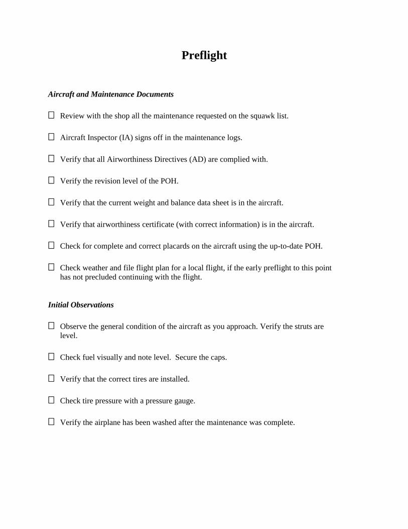
Preflight
Aircraft and Maintenance Documents
Review with the shop all the maintenance requested on the squawk list.
Aircraft Inspector (IA) signs off in the maintenance logs.
Verify that all Airworthiness Directives (AD) are complied with.
Verify the revision level of the POH.
Verify that the current weight and balance data sheet is in the aircraft.
Verify that airworthiness certificate (with correct information) is in the aircraft.
Check for complete and correct placards on the aircraft using the up-to-date POH.
Check weather and file flight plan for a local flight, if the early preflight to this point
has not precluded continuing with the flight.
Initial Observations
Observe the general condition of the aircraft as you approach. Verify the struts are
level.
Check fuel visually and note level. Secure the caps.
Verify that the correct tires are installed.
Check tire pressure with a pressure gauge.
Verify the airplane has been washed after the maintenance was complete.
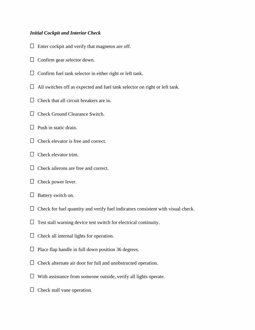
Initial Cockpit and Interior Check
Enter cockpit and verify that magnetos are off.
Confirm gear selector down.
Confirm fuel tank selector in either right or left tank.
All switches off as expected and fuel tank selector on right or left tank.
Check that all circuit breakers are in.
Check Ground Clearance Switch.
Push in static drain.
Check elevator is free and correct.
Check elevator trim.
Check ailerons are free and correct.
Check power lever.
Battery switch on.
Check for fuel quantity and verify fuel indicators consistent with visual check.
Test stall warning device test switch for electrical continuity.
Check all internal lights for operation.
Place flap handle in full down position 36 degrees.
Check alternate air door for full and unobstructed operation.
With assistance from someone outside, verify all lights operate.
Check stall vane operation.

Battery, radio master and magnetos off and secured.
Confirm oxygen system (Matrix only) is functioning and record amount in tank.
Check side or storm window for cracks and security.
Interior checks of seats, belts, cabinets, emergency exit, and cargo netting for security
and cracks.
Check hydraulic fluid level in area aft of baggage storage. Remove panel or use sight
gauge. Add fluid (MIL-H-5606) if necessary.
Check all of the seat backs for integrity and cracks beneath the carpeted backs.
Check the clear plastic document pouch for the presence of the correct airworthiness
certificate and registration.
Verify that the spring loaded seat back release latches are operating normally and not
damaged or binding.
Ensure that required equipment is available in the airplane.
Main Cabin Door (MCD)
Check main cabin door pressure seal.
Inspect the fuselage below and aft of the MCD for skin and paint damage from baggage
transfer.
Visually inspect the cables for broken strands and/or loose hardware. Check the cables
for even tension fore and aft.
Inspect the hinge of the lower half of the MCD for evidence of corrosion.
Left Wing
Verify condition of flaps.

Check presence and condition of Mylar chafe tape under the wing overhang.
Recommend application of chafe tape of top side of flaps.
Check for missing static wicks.
Verify that the two stall strips on each wing, located mid-wing and near the wing root,
are present and secured.
Inspect the aileron.
Confirm that wing tip is absent any hanger rash.
Check all surfaces for loose rivets.
Strobe and navigation lights secured, with no corrosion around light mountings.
Remove Pitot cover.
Verify that the main span “I” beam upper and lower surface is free of cracks or
deformation.
Confirm fuel vent open and clear.
Check carefully the dielectric paint (the flat black paint that borders the boot).
Check boot integrity, looking for pin holes or tears.
Inspect bottom of the wing for fuel leaks.
Check the landing gear doors for security and proper angle of 10 degrees out.
Verify that the squat switch (left gear only) is clean, and all electrical leads attached.
Confirm that struts are inflated 3.5 inches with full fuel.
Verify that there is no excessive play or wear on landing gear torque links.
Check tire condition.

Check brake pad thickness. Minimum allowable thickness is 0.10” or about the
thickness of two stacked pennies.
Verify that the brake line security bolt head is facing away from the tire.
Confirm that no brake lines are leaking.
Verify that the gear actuator attachment point at rod end safe tied.
Ensure that the wheel well is clean of debris.
Drain fuel.
Engine Cowling and Nose Section
Inspect the front baggage area.
Check that the battery drain orifice is open and unobstructed.
Inspect the exhaust pipe.
Ensure that all of the cowling fasteners are present and flush with the cowling.
Inspect the nose gear doors.
Inspect the nose wheel.
Look up into the nose wheel bay for any discrepancies
Inspect the cowling.
Check oil level and condition.
Inspect the propeller.
Test the alternator belt to ensure the belt is tight and verify that the #1 alternator is
attached securely.
Check the heat muff.

Right Wing
Drain fuel.
Repeat inspection as with Left Wing.
Fuselage Right Side
Check emergency exit for security.
Check that the relief tube is operational (using water).
Confirm that the drain vents on bottom of fuselage are clear.
Verify that the A/C drain bevel is facing aft.
Look for oil, hydraulic fluid on belly of aircraft.
Look for corrosion where the alternate static ports and outflow valve pads are located
under aircraft.
Check the inspection port for the rudder and elevator for security.
Check static ports for water contamination.
Check the upper empennage for antenna security.
Horizontal Stabilizer
Check attachment bolts for security.
Move the stabilizer up and down to feel for any movement (none should be felt).
Check boots for attachment and holes.
Check elevator attachment bolts for security and corrosion.

Tail Cone
Check trim tubes for security. No fore or aft play.
Check drain hole in tail cone is clear.
Check rivets on top of horizontal stabilizer.
Rudder
Move the ruder slowly to make sure it is securely attached.
Check attachment bolts visually for security.
Check for cracks or dents.
Fuselage Left Side
Check static ports for water contamination.
Check A/C condenser screens for security.
Inspect oxygen access door (Matrix only) and security of filler cap. Record tank
pressure.
Enter airplane and secure door.
Pilot and Copilot Seats
Check all functions just as with the passenger seats.
Check seats for positive engagement of seat latch, and for installed stops at each seat
track.
Check the height adjustment, the fore/aft slide adjustment and lumbar support function.
Verify proper seat belt function.
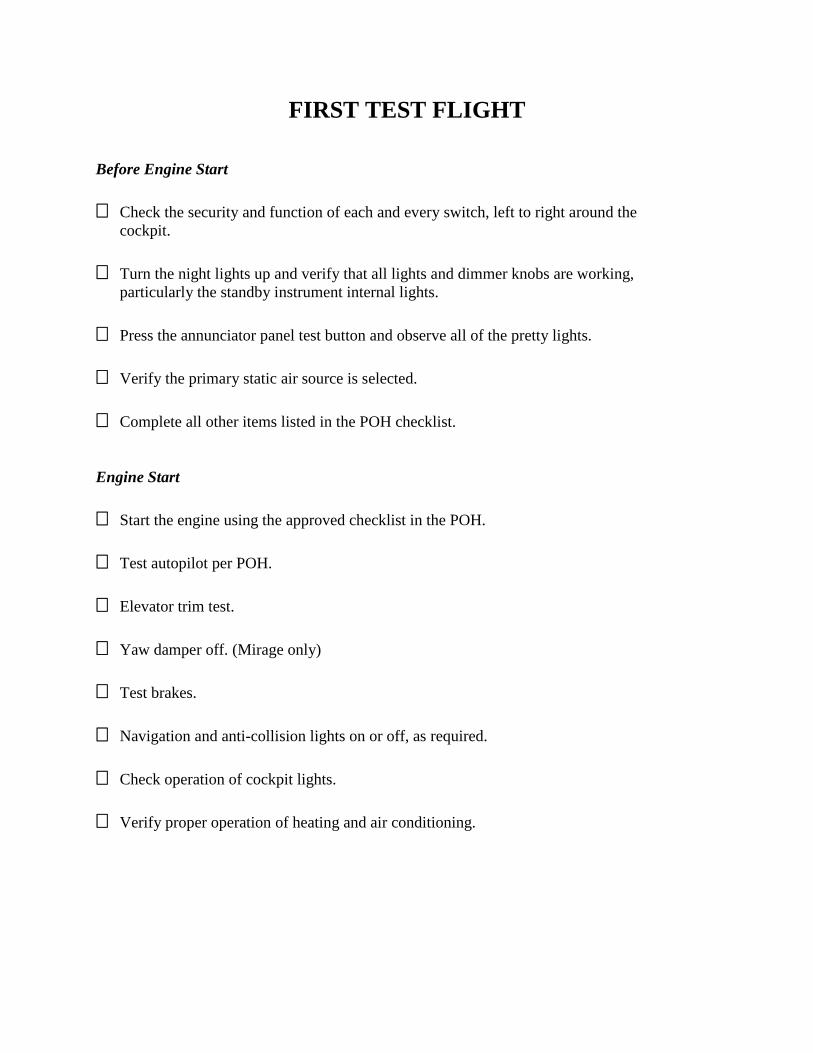
FIRST TEST FLIGHT
Before Engine Start
Check the security and function of each and every switch, left to right around the
cockpit.
Turn the night lights up and verify that all lights and dimmer knobs are working,
particularly the standby instrument internal lights.
Press the annunciator panel test button and observe all of the pretty lights.
Verify the primary static air source is selected.
Complete all other items listed in the POH checklist.
Engine Start
Start the engine using the approved checklist in the POH.
Test autopilot per POH.
Elevator trim test.
Yaw damper off. (Mirage only)
Test brakes.
Navigation and anti-collision lights on or off, as required.
Check operation of cockpit lights.
Verify proper operation of heating and air conditioning.

After Engine Start
Conduct the post-start checklist per the POH, and note any discrepancies.
Note Hobbs time, local time and fuel on board
Verify all data subscriptions are up to date and that all avionics boot up correctly.
Copy and set the clearance into the panel in the usual way.
Check the flight control systems for free and correct operation.
Check the free and normal movement of the power lever.
Check normal operations of the autopilot.
Taxi
Verify braking action on all four pedals if a co-pilot is on board.
Check for play in the rudder steering mechanism. There should be none. Check the
copilot side as well.
Note the free and correct movement of all of the instruments including the compass.
Check the ELT. Plan to run the ELT for a few cycles while monitoring 121.5, but only
during the first 5 minutes after the hour.
Press and hold each Pitot-Static System Condensate Drain for a second or two, and
observe that there are no “nervous” pitot static instruments.
Flaps to take-off position.
Verify COM and NAV frequencies are set properly.
Verify flight instruments.
Check magnetic compass.

Run Up
Listen for any new, changed or unusual sounds.
Follow the procedure for the autopilot check in the POH.
Conduct a full-power check.
Complete a normal run up according to the POH.
Complete a high-speed taxi test.
Take-off/Climb
Identify emergency landing sites near the airport.
Verify again that flaps and trim are in take-off position.
Use normal callouts for the take-off roll and initial climb.
Note engine instrumentation on take-off roll and during climb and record them once the
autopilot is engaged.
Note the length of the take-off roll and record once the autopilot is engaged.
Observe gear cycle time and verify normal operations.
Maintain Vy (110 KIAS) and remain close, within 2 NM of the airport.
Check flight controls.
Confirm the pressurization system is active passing 1,000 ft AGL. (Mirage only)
Low Altitude
Set up for VMC cruise flight between 8,000 and 10,000 AGL if possible; verify all pilot
and copilot instrumentation are in agreement and within limits.

Verify engine parameters are operating in normal range.
Verify proper operation of the fuel system.
Check wing balance and airplane rigging.
Check flap operations and rigging.
Check ice protection.
Verify airspeed indicator operations.
Verify attitude indicator (AI) operations.
Verify turn coordinator operations.
Verify HSI/DG operations.
Verify vertical speed indicator (VSI) operations.
Verify landing gear operations.
Test the Emergency Gear Extension system per the POH.
Engage the autopilot and confirm the settings on the altitude pre-select and autopilot
annunciator panel.
Verify correct operation of the Cabin Pressurization System. (Mirage only)
Activate the alternate static system and verify correct operation.
Test cabin heat and defrost.
Test recirculating blowers and air conditioning.
Reduce power until the gear warning horn sounds (do not stall). Return cruise power
and verify that the horn silencer has reset.
Perform imminent stalls to verify that the stall horn works correctly in dirty and clean
configurations.

Operate and verify correct operation of all threat ID equipment on board: NEXRAD,
RADAR, lightning detection/sferics, terrain awareness, ground proximity warning,
TAS, and TIS.
Test all avionics.
Communicate with ATC and ensure transponder altitude matches aircraft’s.
High Altitude and Cruise
Climb to FL250 if possible, but at least to 14,000 feet.(12,500 for Matrix)
Check max cabin pressure differential. (Mirage only)
Lean the engine to high, normal, and low cruise power settings, and confirm power
settings and fuel flows per the POH.
Check all on board navigation gear for reception and accuracy.
Maneuver aircraft in a variety of turns and climbs to ensure control surface responses.
Ensure that all gear fall free with minimum rudder or elevator input.
Check electrical loads.
Confirm proper function of fuel system and boost pump.
Check operation of the CABIN ALT. (Mirage only)
Complete any additional checks the mechanic may have requested if he is not in the
airplane.
Conduct an emergency descent per the POH.

Arrival
Reduce power slowly.
Fly numerous approaches.
Test brakes before landing.
Landings
Complete several landings.
Test brakes.
Shutdown
Normal engine shutdown.
Note Hobbs and total elapsed time.
Complete shutdown per the POH.
Record remaining oxygen pressure (Matrix only).
Post Flight
Check the exterior of the aircraft for evidence of leaks.
Log all discrepancies noted during preflight and flight.

NOTES
____________________________________________________________________________________
____________________________________________________________________________________
____________________________________________________________________________________
____________________________________________________________________________________
____________________________________________________________________________________
____________________________________________________________________________________
____________________________________________________________________________________
____________________________________________________________________________________
____________________________________________________________________________________
____________________________________________________________________________________
____________________________________________________________________________________
____________________________________________________________________________________
____________________________________________________________________________________
____________________________________________________________________________________
____________________________________________________________________________________
____________________________________________________________________________________
____________________________________________________________________________________
____________________________________________________________________________________
____________________________________________________________________________________
____________________________________________________________________________________
____________________________________________________________________________________
____________________________________________________________________________________
____________________________________________________________________________________
____________________________________________________________________________________
____________________________________________________________________________________
____________________________________________________________________________________
____________________________________________________________________________________