electrical - mirage performancetech.mirage-performance.com/manuals/mirage service...
TRANSCRIPT

54-1
ELECTRICAL CONTENTS
AIR CONDITIONING ............... Refer to GROUP 55
SYSTEM ......................... Refer to GROUP 13G AUTOMATIC SEAT BELT ......... Refer to GROUP 52A BATTERY ............................................ 3
SERVICE ADJUSTMENT PROCEDURES . . . . . . . . . . . . 3
AUTO-CRUISE CONTROL
Battery Charging .............................. . 3 Battery Inspection .............................. 3 Battery Testing Procedure ...................... . 4
BUZZER ........................................... 50 BUZZER ........................................ 50 TROUBLESHOOTING ............................ 50
CIGARETTE LIGHTER .............................. 58 CIGARETTE LIGHTER ........................... 59 TROUBLESHOOTING ............................ 58
CLOCK ............................................ 60 CLOCK ......................................... 61 TROUBLESHOOTING ............................ 60
COLUMN SWITCH* ................................ 46 DOOR GLASS AND REGULATOR (POWER WINDOWS) .............. Refer to GROUP 42 DOOR HANDLE AND LATCH (CENTRAL DOOR LOCKING SYSTEM) ......................... Refer to GROUP 42
I
110003620
DOOR MIRROR (ELECTRONIC CONTROL DOOR MIRROR) .................. Refer to GROUP 51 HEADLIGHT ....................................... 19
SPECIAL TOOL SERVICE ADJUSTMENT PROCEDURES . . . . . . . . . . 22
. . . . . . . Headlight Aiming . . . . . . . . . . . . . . . 22 Bulb Replacement ............................ 25
SERVICE SPECIFICATIONS ...................... 19 TROUBLESHOOTING .. . . . . . . . . . . . . . . . . . . . 20
HEATER .......................... Refer to GROUP 55 HIGH MOUNTED STOP LIGHT ...................... 43
TROUBLESHOOTING . . . . . . . . . . . . . . . 43 HORN .........................
HORN .......................................... 55 TROUBLESHOOTING ............................ 52
IGNITION SWITCH .................................. .5 INTERIOR LIGHT ................................... 44
. . . . . . . .
TROUBLESHOOTING . . . . . . . .
CONTINUED ON NEXT PAGE
WARNINGS REGARDING SERVICING OF SUPPLEMENTAL RESTRAINT SYSTEM (SRS) EQUIPPED VEHICLES
WARNING! (1) Improper service or maintenance of any component of the SRS, or any SRS-related component, can lead to
personal Injury or death to service personnel (from inadvertent firing of the air bag) or to the driver and passenger (from rendering the SRS inoperative).
(2) Service or maintenance of any SRS component or SRS-related component must be performed only at an authorized MlTSUBlSHl dealer.
(3) MlTSUBlSHl dealer personnel must thoroughly review this manual, and especially its GROUP 52B -Supple- mental Restraint System (SRS) and GROUP 00- Maintenance Service, before beginning any service or mainte- nance of any component of the SRS or any SRS-related component.
NOTE The SRS includes the following components: SRS air bag control unit, SRS warning light, air bag module, clock spring and interconnecting wiring. Other SRS-related components (that may have to be removedhnstalled in connection with SRS setvice or maintenance) are indicated in the table of contents by an asterisk (*).

54-2
METERS AND GAUGES .............................. 7 METERS AND GAUGES SEALANTS . . . . . . . . . . . . SERVICE ADJUSTMENT PROCEDURES .. . . . . . . . . 12
Engine Coolant Temperature Gauge Simple Inspection ...................... 15 Engine Coolant Temperature Gauge Unit Inspection
HAZARD LIGHT .................................... 28 PARKING AND SIDE-MARKER LIGHT. HAZARD LIGHT 37 TROUBLESHOOTING ............................ 28
RADIATOR (RADIATOR FAN MOTOR) ......... Refer to GROUP 14 RADIO AND TAPE PLAYER ........................ 62
RADIO AND TAPE PLAYER ...................... 85 TROUBLESHOOTING ............................ 62
REAR COMBINATION LIGHT ....................... 39 REAR COMBINATION LIGHT ..................... 42 TROUBLESHOOTING ............................ 39
REAR WINDOW DEFOGGER ....................... 88 REAR WINDOW DEFOGGER .................... 91 SERVICE ADJUSTMENT PROCEDURES .. . . . . . . . . 90
Printed-heater Line Check ..................... 90 Printed-heater Line Repair ..................... 90
TROUBLESHOOTING ............................ 88 RHEOSTAT ........................................ 48

CHASSIS ELECTRICAL - Battery 54-3
White Blue I I
Charging Good, necessary condition
16Y1814
16F0123
00001 560
BATTERY 110003621
SERVICE ADJUSTMENT PROCEDURES BATTERY INSPECTION BATTERY VISUAL INSPECTION (1) The battery contains a visual test indicator which gives blue signal when an adequate charge level exists, and white signal when charging is required. BATTERY VISUAL INSPECTION (2) Make sure ignition switch is in OFF position and all battery feed accessories are OFF. I .
2.
3.
4.
5.
6.
7.
8. 9.
Disconnect ground cable from battery before disconnecting (+) cable. Remove battery from vehicle. Caution Care should be taken in the event battery case is cracked or leaking to protect hands from the electrolyte. A suitable pair of rubber gloves (not the household type) should be worn when removing battery by hand. Inspect battery carrier for damage caused by loss of acid from battery. If acid damage is present, it will be necessary to clean area with a solution of clean warm water and baking soda. Scrub area with a stiff bristle brush and wipe off with a cloth moistened with ammonia or baking soda in water. Clean top of battery with same solutions as described in step 3. Inspect battery case and cover for cracks. If cracks are present, battery must be replaced. Clean the battery post with a suitable battery post cleaning tool. Clean the inside surfaces of the terminal clamps with a suitable battery terminal cleaning tool. Replace damaged or frayed cables and broken terminal clamps. Install the battery in vehicle. Connect (+) and (-) cables to battery in the order of mention.
-- -: :
10. Tighten the clamp nut securely.
BATTERY CHARGING 110003622
Caution When batteries are being charged, an explosive gas forms beneath thecover of each cell. Do not smoke near batteries on charge or which have recently been charged. Do not break live circuits at the terminals of the batteries on charge. A spark will occur where the live circuit is broken. i _"
Keep all open flames away from the battery. . ,

54-4 CHASSIS ELECTRICAL - Batterv
~
(1) Remove hold-downs and shields (2) Check for brokenkracked case or cover
Battery electrolyte temperature may temporarily be When the dot appears or when maximum charge allowed to rise to 55°C (131°F). Increase of electro- shown below is reached, charging should be lyte temperature above 55°C (131°F) is harmful stopped. to the battery, causing deformation of battery cell, NOTE
If the indicator does not turn to blue even after decrease in life of battery, etc. CHARGE RATE the battery is charged, the battery should be re- If the test indicator IS white, the battery should be placed; do not overcharge. charged as outlined below.
- Replace battery
Charge Rate Chart Battery I 55B24R (433 amps) 1 Battery I 55B24R (433 amps)
(4) Read open circuit voltage
Charge Rate Chart Battery I 55B24R (433 amps) 1 Battery I 55B24R (433 amps)
Re-test
Slow charging
(1) Connect a load tester to the battery. (2) Load the battely at the recommended discharge rate (see
(4) Compare the measured value with the minimum voltage (See
LOAD TEST RATE CHART) for 15 seconds I(3) Read voltage after 15 seconds, then remove load 1 LOAD TEST CHART)
OK. Hiaher than the minimum voltaae
1 5 amps 10 hrs.
+ Replace battery
1 10 amps 5 hrs.
Application
Fast charging I
55B24R
20 amps 2.5 hrs. t 30 amps 1.5 hrs.
BATTERY TESTING PROCEDURE 110003623
TEST STEP
+OK Normal
LOAD TEST CHART I Temperature 21 (70) I 16 (60) 10 (50) 1 4 (40) I -1 (30) 1 -7 (20) I -12 (10) 1-18 (0) "C (OF) I and I
I 1 above I I I I I I I
I 9.6 Minimum voltage 1 9.5
, 1 9.1 I i 8.9 I 8.7 1 85
LOAD TEST RATE CHART
Cranking rating (0°F) 433 amps
Reserve capacity 79 minutes

CHASSIS ELECTRICAL - lanition Switch 54-5 - .
IGNITION SWITCH REMOVAL AND INSTALLATION 110003624
4 A b
5
1 A1650124
Steering lock cylinder removal steps 1. Knee protector 2. Column cover lower 3. Column cover upper 4. Ignition key ring 5. Steering lock cylinder
Ignition switch segment removal aeps 1. Knee protector 2. Column cover lower 3. Column cover upper 6. Ignition switch
-
Lock pin 21650339
Key reminder switch removal steps 1. Knee protector 2 Column cover lower - - 3. Column cover upper 7. Push nut
+b 8. Key reminder switch
REMOVAL SERVICE POINTS + A F STEERING LOCK CYLINDER REMOVAL (1) Insert the key in the steering lock cylinder and turn it
to the “ACC” position. (2) Using a cross-tip (+) screwdriver (small) or a similar tool,
push the lock pin of the steering lock cylinder inward and then pull the steering lock cylinder toward you.
+Bb KEY REMINDER SWITCH REMOVAL Insert a flat-tipped screwdriver or similar tool in the slot and pry out the projection as indicated by an arrow to remove the connector.
-
I TSB Revision I

54-6 CHASSIS ELECTRICAL - Ignition Switch
1 2 3 4 5 position
Z16L0300
6
INSPECTION IGNITION SWITCH (1) Remove the knee protector, and the column cover. (2) Disconnect the wiring connector from the ignition switch,
and connect an ohmmeter to the switch side connector. (3) Operate the switch, and check the continuity between
the terminals.
I Ignition I Terminal No.
3 START
KEY REMINDER SWITCH (1) Remove the knee protector, and the column cover. (2) Remove the ignition switch mounting screws and pull out
(3) Disconnect the connector of the key cylinder switch. (4) Insert the key into and remove it from the steering lock
the ignition switch.
cylinder to check for continuity between the terminals.
I Ignition I Terminal No.
I I I I I 1 I
Pull out 101
1 I I I I I
CHASSIS ELECTRICAL - Meters and Gauaes
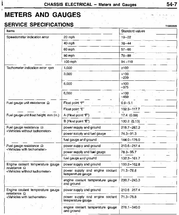
20 mph
54-7
Standard values
19-22
METERS AND GAUGES -- .
3,000
5,000
6,000
Float point “F”
Float point “ E
A (Float point “ F )
SERVICE SPECIFICATIONS 1100036
+loo -200
+loo -375
+loo -450
0.9-5.1
102.3-1 17.7
17.4 (0.69)
Items
power supply and ground
power supply and fuel gauge
fuel gauge and ground
power supply and ground
power supply and engine coolant temperature gauge
engine coolant temperature gauge and ground
power supply and ground
power supply and engine coolant temperature gauge
Speedometer indication error
210.6-257.4
78.3-95.7
132.3-161.7
133.2-162.8
71.3-78.8
200.7-245.3
210.6-257.4
71.3-78.8
Tachometer indication error rpm
Fuel gauge unit resistance R
Fuel gauge unit float height mm (in.)
Fuel gauge resistance 12 <Vehicles without tachometers
-
Fuel gauge resistance 8 <Vehicles with tachometer>
Engine coolant temperature gauge resistance R <Vehicles without tachometer>
Engine coolant temperature gauge resistance S2 <Vehicles with tachometer>
engine coolant temperature gauge I 278.1 -340.0 and ground I

54-8 CHASSIS ELECTRICAL - Meters and Gauges
CIRCUIT DIAGRAM
IGNIT I - -
COMBINATION METER
B
28
COIL - IGNITION SWITCH (IG1)
' IGNIT'ON
.MFI SYSTEM S Y a T E M
ACTOMPTIC S E A T BZLT (UP T O ALY4MODELS) SYSTEM A U T O - C H U I S E MF SYSTEM
' TG*$ITION COMTEOL SYSTEM AUTOMAT I C S E A T BELT (UP .O 1YY4 MUDELS) BUZZER

CHASSIS ELECTRICAL - Meters and Gauges 54-9
I
:Q
Y
Y
B
1. 258
1.25B
2B
4
0 (Dm
6
ENGI ME CONTROL MODULE
. .
- NOTE :< 1 : 1993 MODELS. ::2:FROM 1994 MODELS.
HEIOMOOAB
TSB Revision

54-1 0 CHASSIS ELECTRICAL - Meters and Gauges
CIRCUIT DIAGRAM (CONTINUED)
T A I LL 11 2R-1
FEDACATED
G-li
I G-W
G-I + TAILLIGHT, PARKING AND SIDE-MARKER LiGHT AND LICENSE PLATE LIGHT r
L G-b
.3-SPEED B-k AUTOMATIC TRANSAXLE
SYSTEM AUTOMATIC TRANSAXLE
.AIR CONDITIONING
.ELC 4-SPFED
B-'
B-' ,AUTO-CRUISE CONTROL
,CIGARETTE LitiHTER ,REAR WINDOW
SYSTEM
DEFOGGER
1 (B-Y)
B - l
' R E L A Y
1
'0 0 G-W v
,AUTO-CRUISE CONTROL SYSTFM .CIGARETTE
.HEAR WINDOW L I GHTER DEFOGGER
.--i
G - h 9
' HEATER ,RADID AND TAPE PLAYFR
T ~ - y I R H E O S T A T
(ELECTRONIC TYPE)
2 0
COk ME?
J 1 - B
1 TURN-SIGNAL LIGHT AND HAZARD LIGHT
TURN-SIGNAL LIGHT AND HAZARD LIGHT v
B-Y I
YOTE %2:FROM 1994 MODELS. 1 : 1993 MODELS.
\TI ON
R H F O S T A T (MECHANICAL TYPE) m
J/B qL

CHASSIS ELECTRICAL - Meters and Gauges 54-1 1
Items
Engine coolant temperature gauge unit threaded portion
-- - SEALANTS
Specified sealants
3M Adhesive nut locking No. 4171 or equivalent
11 0003626
TROUBLESHOOTING OPERATION <Fuel gauge>
, 0
0
When the ignition key is at the “ON” position, the fuel gauge is activated. When there is much fuel, the unit’s resistance is small and the current flowing in the circuit is great, so the gauge’s indicator indicates in the “ F area. When there is little fuel, the unit’s resistance is high and the current flowing in the circuit is small, so the gauge’s indicator indicates in the “E” area.
When the ignition key is at the “ON” position, the engine coolant temperature gauge is acti- vated. When the engine coolant temperature is high, the unit’s resistance is low and there is a great flow of current in the circuit, so the gauge’s indicator indicates in the “ H area. When the engine coolant temperature is low, the unit’s resistance is high and there is a small flow of current in the circuit, so the gauge’s indicator indicates in the “ C area.
Pulses are produced in accordance with the vehicle speed, and vehicle-speed signals are input to systems (the transaxle-control system, etc.) that regulate according to the vehicle speed.
0
<Engine coolant temperature gauge> 0
0
0
<Reed switch>
110003627
TROUBLESHOOTING HINTS 1. The fuel gauge doesn’t function, or shows the
incorrect indication. 1) Disconnect the connector of the fuel gauge
unit; the “F” side is indicated when terminal 1 is then grounded. 0 Check the fuel gauge.
2. The engine coolant temperature gauge doesn’t function, or shows the incorrect indication. 1) The “H” side is indicated when the connector
of the engine coolant temperature gauge unit is disconnected and then grounded. 0 Check the engine coolant temperature
gauge unit. 3. Systems dependent upon control according to
the vehicle speed do not function correctly. 0 Check the reed switch (located within the
speedometer). 4. The meter illumination light does not illuminate.
1) The tail lights illuminate. Check the rheostat.
COMPONENT LOCATION
Engine control module
54-1 2 CHASSIS ELECTRICAL - Meters and Gauaes
Z16P0296
Anchoring bars ,
Front
Anchor plate
6- Z16P0209 I I
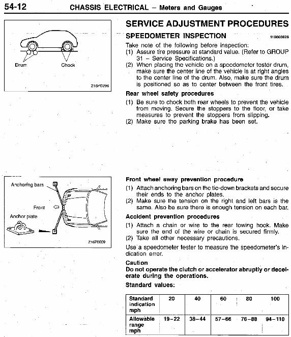
SERVICE ADJUSTMENT PROCEDURES
Take note of the following before inspection: (1) Assure tire pressure at standard value. (Refer to GROUP
31 - Service Specifications.) (2) When placing the vehicle on a speedometer tester drum,
make sure the center line of the vehicle is at right angles to the center line of the drum. Also, make sure the drum is positioned so as to center between the front tires.
SPEEDOMETER INSPECTION 110003628
Rear wheel safety procedures (1) Be sure to chock both rear wheels to prevent the vehicle
from moving. Secure the stoppers to the floor, or take measures to prevent the stoppers from slipping.
(2) Make sure the parking brake has been set.
Front wheel sway prevention procedure (1) Attach anchoring bars on the tie-down brackets and secure
their ends to the anchor plates. (2) Make sure the tension on the right and left bars is the
same. Also be sure there is enough tension on each bar. Accident prevention procedures (1) Attach a chain or wire to the rear towing hook. Make
sure the end of the wire or chain is secured firmly. (2) Take all other necessary precautions. Use a speedometer tester to measure the speedometer’s in- dication error. Caution Do not operate the clutch or accelerator abruptly or decel- erate during the operations. Standard values:
!33;dard ~ 20 ~ 40 ~ 60 ~ 80 ~ 100 indication
Allowable 19-22 38-44 57-66 76-88 94-110 range mPh

CHASSIS ELECTRICAL - Meters and Gauaes 54-1 3
3 Z16SO303
TACHOMETER INSPECTION 110003629
(1) Insert paper clip into the engine revolution speed detection terminal provided in the engine compartment, and connect the engine tachometer to the inserted paper clip. Caution As the tachometer is negative grounded, do not con- nect battery conversely to prevent damaging transis- tor and diode. NOTE For tachometer inspection, use of a fluxmeter-type engine tachometer is recommended. (Because a fluxmeter only needs to be clipped to the high tension cable.)
(2) Connect the engine tachometer and compare the engine tachometer and tachometer readings. Replace tachometer if difference IS excessive.
t :
Standard value: f
Indicated variation -200 rlmin
6,000
+loo -450
c
FUEL GAUGE SIMPLE INSPECTION
Remove the fuel gauge unit coupling connector.
1 Connect a test light to the [ness connector.
t )he test light and gauge conditions.
I 1. Test light lights. (Pointer of gauge does not swing.) 1 p:Test light lights. (Pointer of gauge swings.)
3. Test light does not light. (Pointer of gauge does not swing.)
110003630
+ Replace fuel gauge.
+I Replace fuel gauge unit.

54-1 4 CHASSIS ELECTRICAL - Meters and Gauges
I Z16P0143 I
Fuel gauge terminal
I
Ground terminal
Z16PO144
Z16PO145
FUEL GAUGE UNIT INSPECTION 110003631
To check, remove fuel gauge unit from fuel tank. (Refer to GROUP 13F - Fuel Tank.)
Float Height of Fuel Gauge Unit Move float and measure the height at point F (highest) and point E (lowest) with float arm touching stopper. Standard value: Point F: 17.4 mm (.69 in.)
Point E: 130.2 mm (5.13 in.)
Standard Resistance of Fuel Gauge Unit (1) Check that resistance value between the fuel gauge termi-
nal and ground terminal is at standard value when fuel gauge unit float is at point F (highest) and point E (lowest). Standard value: Point F: 9-5.1 R
Point E: 102.3-117.7 R (2) Check that resistance value changes smoothly when float
moves slowly between point F (highest) and point E (low- est).
FUEL SENSOR Connect fuel gauge unit to battery via test light (12V-3.4W). Immerse in water. Condition good if light goes off when unit thermistor is in water and lights when unit is removed from water. Caution After completing this test, wipe the unit dry and install it in the fuel tank.

CHASSIS ELECTRICAL - Meters and Gauges 54-1 5
-
ENGINE COOLANT TEMPERATURE GAUGE SIMPLE INSPECTION
Replace water temperature gauge.
temperature gauge unit cou- pling connector.
Connect the harness connector . via a test light to the ground.
+
Place the ignition switch in the ' ON Dosition.
Replace water temperature gauge unit.
4
-
Check the test light and gauge conditions.
Correct harness. I
I 1. Test light lights. (Pointer of gauge does not swing.) I
Circuit
Sens
zi cow9
1 2. Test light lights. (Pointer of gauge swings.) I
ENGINE COOLANTTEMPERATURE GAUGE UNIT
To check, remove engine coolant temperature gauge unit from intake manifold. Standard Resistance of Engine Coolant Temperature Gauge Unit (1) Immerse unit in 70°C (158°F) water to measure resistance.
INSPECTION 11 0003633
Standard value: 104k13.5 !2
3. Test light does not light. (Pointer of gauge does not swing.)
110003632

54-1 6 CHASSIS ELECTRICAL - Meters and Gauges
METERS AND GAUGES REMOVAL AND INSTALLATION 11 0003634
Removal steps 1. Meter bezel 2. Combination meter 3. Adapter 4. Speedometer cable
4 A b 4w
Adapter
k
Z16S0280
Z1680325 v
REMOVAL SERVICE POINTS + A b ADAPTER REMOVAL (1) Remove the adapter lock. (2) Pull the speedometer cable slightly into the passenger
Compartment, and remove the rear side of the adapter from the cable.
(3) After turning the adapter so that the notched section is aligned with the tab on the cable side, remove the adapter by sliding it backwards.
ABb SPEEDOMETER REMOVAL Tie a cord to the end of the speedometer cable that is in the passenger compartment. Then remove the grommet inside the engine compartment, and pull the cable into the engine compartment.
1 TSB Revision I

CHASSIS ELECTRICAL - Meters and Gauges 54-1 7
I Z16S0082
<Vehicles without tachometer>
Engine coolant temperature
<Vehicles with tachometer>
Engine cS- Power coolant / temperature
, Ground
-ie Z1650079
INSPECTION REED SWITCH Using an ohmmeter, check that continuity and discontinuity alternates between terminals 1 and 2 four times at every rota- tion of the shaft of the speedometer cable connection.
FUEL GAUGE RESISTANCE AND ENGINE COOLANT TEMPERATURE GAUGE RESISTANCE <Vehicles without tachometer> (1) Remove the power supply tightening screw. (2) Use an ohmmeter to measure the resistance value be-
tween the terminals. Caution When inserting the testing probe into the power supply terminal, be careful not to touch the printed board. Standard value:
Fuel gauge resistance Power supply-Ground: 21 8.7-267.3 Q Power supply-Fuel gauge: 74.7-91.3 R Fuel gauge-Ground: 144.0-176.0 Q
Engine coolant temperature gauge resistance Power supply-Ground: 133.2-162.8 rr Power supply-Engine coolant temperature gauge: 71.3-78.8 s2 Engine coolant temperature gauge-Ground: 200.7-245.3 s2
<Vehicles with tachometer> Use an ohmmeter to measure the resistance value between the terminals.
Standard value: Fuel gauge resistance
Power supply-Ground: 210.6-257.4 Cl
Power supply-Fuel gauge: 78.3-95.7 Q
Fuel gauge-Ground: 132.3-161.7 s2 Engine coolant temperature gauge resistance
Power supply-Ground: 210.6-257.4 Q
Power supply -Engine coolant temperature gauge: 71.3-78.8 s2 Engine coolant temperature gauge-Ground: 278.1 -340.0 i2

54-1 a CHASSIS ELECTRICAL - Meters and Gauges
DISASSEMBLY AND REASSEMBLY 110W3635
<Vehicles without tachometer>
<Vehicles with tachometers
Zi650077
Z1650078 \ 1
Disassembly steps 1. Meter glass, window plate 2. Engine coolant temperature gauge
<Vehicles without tachometer> Fuel gauge, engine coolant temperature gauge <Vehicles with tachometer>
<Vehicles without tachometer> Speedometer, tachometer <Vehicles with tachometer>
<Vehicles without tachometer>
3. Speedometer
4. Fuel gauge
5. Bulb, socket 6. Printed-circuit board 7. Meter case
00001 561

CHASSIS ELECTRICAL - Headlight 54-1 9
Items
Headlight intensity
HEADLIGHT
Limit
20,000 cd or more
SPECIAL TOOL Tool Tool number and name
Headlight aimer
Supersession
General service tool
110003637
Application
Headlight aiming

54-20 CHASSIS ELECTRICAL - Headlight
0 . 85R W
TROUBLESHOOTING 110003638
'2 " 3 rn !A31) "3 "2 2
w m io
E UI m 6 0.85R 6
I )
CIRCUIT DIAGRAM
I .
FUSIBLE LINK 0 1. 25R-B
2 R - B
_ _ _ _ _ _ _ _ _ _ _ _ _ _ _ _ _ TAILLIGHT 'CHARGI MG PARKING AfJD SIDE MARKER SYSTEM LIGHT AND LICENSE PLATE LIGHT
2R-I
Y-R
Y-I;
I
2R-L I
DED I CATED FUSE
0
I I
R I
R-Y ( R - Y )
R-'
R-Y
i r
3
3 0
TAIL RELE
G-Y i: (G-Y)"'
x _ _ _ _ _
I GHT
LI 1. 25B I
!OTE ,~ 1 : 1993 MODELS. X2:FROM 1094 MODELS. ::3:UP TO 1994 MODELS 1 :4 :FROM 1995 MODELS.

CHASSIS ELECTRICAL - Headlight
Lighting switch Dimmer/passing switch
“HEAD” -
- “PASS”
OPERATION Conditions for switch-ON of headlight relay See the fig.1. <Low-beam operatiom 0
0
The headlight relay is switched ON when the lighting switch is set to the “HEAD position. The low beam of the headlights will illuminate when, in this condition, the dimmedpassing switch is set to the “LO position.
!
<Upper-beam operatiom c 0 The headlight relay is switched ON when the
lighting switch is set to the “HEAD position. The high beam of the headlights will illuminate when, in this condition, the dimmedpassing switch is set to the “HI” position.
This indicator illuminates during use of the high beam of the headlights, and when the passing signal (high beam) is activated, thus indicating that the headlights’ high beam is illuminated.
When the dimmer/passing switch is set to the “ON” position, the headlight relay is switched ON and the upper beam of the headlight illumi- nates.
0
<Upper-beam indicator light> 0
’ <Passing operatiom 0
Headlight relay
ON
ON
TROUBLESHOOTING HINTS 1. Headlights don’t come on.
1) But the tail lights do illuminate. 0 Check the headlight relay. 0 Check the lighting switch.
2) The tail lights also don’t illuminate. 0 Check the fusible link No. 3.
2. The low beam at both sides doesn’t illuminate. 0 Check the “LO contacts of the dimmer
switch. 3. The upper beam at both sides doesn’t illuminate.
1) The passing signal functions OK. 0 Check the “HI” contacts of the dimmer
switch. 2) The passing signal doesn’t function.
0 Check the dimmer switch. 4. One headlight doesn’t illuminate.
0 Check the bulb. 5. Can’t switch from lowto high beam orvice-versa.
0 Check the dimmer switch. 6. The high beam indicator light doesn’t illuminate.
1) The high beam of the headlights is normal. 0 Check dedicated fuse No. 4. 0 Check the bulb.
. COMPONENT LOCATION
Headlight relay

54-22 CHASSIS ELECTRICAL - Headlight
-
rear tire
Must be used
SERVICE ADJUSTMENT PROCEDURES HEADLIGHTS AIMING 11 0003639
PRE-AIMING INSTRUCTIONS 1. Test dimmer switch operation. 2. Observe operation of high beam light mounted in instru-
ment cluster. 3. Inspect for badly rusted or faulty headlight assemblies.
These conditions must be corrected before a satisfactory adjustment can be made.
4. Place vehicle on a level floor. 5. Bounce front suspension through three (3) oscillations
by applying body weight to hood or bumper. 6. Inspect tire inflation. 7. Rock vehicle sideways to allow vehicle to assume its nor-
mal position. 8. If fuel tank is not full, place a weight in trunk of vehicle
to simulate weight of a full tank [3 kg (6.5 Ibs.) per gallon]. 9. There should be no other load in the vehicle other than
driver or substituted weight of approximately 70 kg (150 Ibs.) placed in driver’s position.
10. Thoroughly clean headlight lenses.
1. Calibration fixture
3. Level vial 4. Floor level offset dial 5. Horizontal dial knob 6. Vertical dial knob 7. Aimer level vial 8. Level vial bubble 9. Top port hole 10. Viewing port
2. Thumb adjusting screws Z16B0245
COMPENSATING THE AIMERS FOR FLOOR SLOPE The floor level offset dial must coincide with the floor slope for accurate aiming. Calibration fixtures are included with the aimers. 1. Attach one calibration fixture to each aimer. Fixtures will
easily snap into position on aimer when properly posi-
Bubble not centered Bubble centered 21680246
2.
I
3.
4.
5.
6.
tioned. Place aimers at center line of each wheel on one side of vehicle. Unit A must be placed at rear wheel with target facing forward. Unit B must be placed at front wheel with target facing rearward. Adjust thumb adjusting screw on each calibration fixture by turning either clockwise or counterclockwise until level vial bubble registers in a centered, level position. Look into top port hole of Unit A. Turn horizontal knob
I until split image is aligned. Transfer plus or minus reading indicated on horizontal dial to floor level offset dial on each aimer. Press floor
I Remove calibration fixtures from both units. level dial inward to set reading.
1 I
TESTING AlMER CALIBRATION The aimer calibration may be off due to extended use. Calibra- tion fixtures used in conjunction with aimers can be used to check and adjust aimers. 1
1. Turn thumb adjusting screw on each calibration fixture until it is approximately the same distance as the supporting posts. I
2. Attach calibration fixtures to each unit with level vials on top. 3
1 I TSB Revision

CHASSIS ELECTRICAL - Headlight 54-23
Small universal I - adaptor
-4 216PO334
Sight openings (Must face each other)
Z16sOO87
Split Image Split image not aligned aligned Z16K1749
3. Locate a true vertical plate glass window or smooth surface and secure aimers three to five feet apart so split image targets can be located in viewing ports.
4. Set floor level dial at zero. 5. Rotate thumb adjusting screws on each calibration fixture
until level vials on fixtures are centered. 6. With both calibration level vials centered, turn vertical dial
knobs on each aimer until aimer level vials are centered. If aimer vertical dial pointers read between 1/2 up and 1/2 down, aimers are within allowable vertical tolerance. Recalibrate units if beyond these limits. Vertical dial pointer reading (on each aimer): 112 up to 112 down
7. Adjust horizontal dial knob on each aimer until split image targets align. I f aimer horizontal dial pointers read between 1 left and 1 right, the aimers are within allowable tolerance limits. Recalibrate units if beyond these limits. Horizontal dial pointer reading (on each aimer): 1 left to 1 right
MOUNTING AIMERS 1. If necessary to expose adjusting screws, remove headlight
trim rings. 2.
full contact with aimer mounting flange. Snap proper adaptor into position on each aim
3. Position aimers on headlights by pushing piston handle forward, engaging rubber suction cup. Immediately pull back piston handle until it locks in place. NOTE Steel inserts are molded into position on the adaptor to insure accuracy. These inserts must be in contact with the three guide points on the lights when the aimers are properly positioned.
HORIZONTAL ADJUSTMENT 1. Set horizontal dial to zero. 2. Check to see that the split image target lines are visible
in the viewing port. If necessary, rotate each aimer slightly to locate the target.
3. Turn horizontal screw on side of headlight until split image of target line appears in mirrors as one solid line. To remove “backlash”, make final adjustment by turning adjusting screw in a clockwise direction.
4. Repeat the last three steps on opposite headlight.
1 TSB Revision

CHASSIS ELECTRICAL - Headlight
(r& : ) c F 3 3 Bubble not Bubble 216K1748 centered centered
Vertical center line ahead of 1 z p I/ right headlight I
1
Height of light centers
Vertical center lineahead of left headlight
nign I 1 area High intensity area
I
I l l Z16K771
VERTICAL ADJUSTMENT 1. The vertical dial should be set at zero. (For passenger
vehicles an “ 0 setting is generally required. For special settings, consult local state laws.)
2. Turn vertical adjusting screw until the level bubble is cen- tered between the lines.
3. Repeat the last two steps on the opposite headlight. 4. Re-check target alignment on both aimers and readjust
horizontal aim if necessary. 5. Remove aimers by pressing “vacuum release” button lo-
cated on piston handle.
AIMING WITH SCREEN HEADLIGHT AIM PREPARATION Place vehicle on a known level floor 7.6 m (25 feet) from aiming screen or light colored wall. Four lines of adhesive tape or like are required on screen or wall: 1. Position a vertical tape so that it is aligned with the vehicle
center line. 2. Position a horizontal tape with reference to center line
of headlight. 4
3. Position a vertical tape on the screen with reference to the center line of each of headlights.
VISUAL HEADLIGHT ADJUSTMENT 1. A properly aimed lower beam will appear on the aiming
screen 7.6 m (25 feet) in front of the vehicle. The shaded area as shown in the illustration indicates high intensity zone.
2. Adjust low beam of headlights to match the low beam pattern of the right and left headlights. Caution When adjusting one headlight, the other headlight should be turned off if possible. If this is not possible, do not cover the other headlight for more than three minutes while it is turned on. Otherwise, heat from the bulb may warp the headlight lens. NOTE Once the headlight low beams have been visually adjusted, high beam adjustment is unnecessary.
LUMINOUS INTENSITY MEASUREMENT Measure the luminous intensity of headlights with a photometer in accordance with the instruction manual prepared by the manufacturer of the photometer and make sure that the lumi- nous intensity is within the following limit. Limit: 20,000 cd or more NOTE (1) When measuring the luminous intensity of headlight, keep
the engine at 2,000 r/min and have the battery changed. (2) If there are specific regulations for luminous intensity of
headlights in the region where the vehicle is operated, make sure that the intensity conforms to the requirements of such regulations.
1

CHASSIS ELECTRICAL - Headlight 54-25
BULB REPLACEMENT 1. 2. 3.
110003640
4.
Disconnect the connector. Turn and remove the locking cap. Pull out the bulb. Caution Do not touch the surface of the headlight bulb with hands or dirty gloves. If the surface dies become dirty, clean it with alcohol or thinner, and let it dry thoroughly before installing Push the locking cap toward the front of the vehicle while it is turned and installed. NOTE If the locking cap is not securely installed, the lens will be out of focus, or water will get inside the light unit, so the cap should be securely installed.

54-26 CHASSIS ELECTRICAL - Headlight
HEADLIGHT REMOVAL AND INSTALLATION 110003641
Removal steps
2. Radiator grille 4 A b b B 4 1. Front turn-signal light
(Refer to GROUP 51 - Radiator Grille)
4Bb .A+ 3. Headlight
Z16S0040
i
REMOVAL SERVICE POINTS 4 A b FRONT TURN SIGNAL LIGHT REMOVAL Remove the set spring, and pull the front turn signal light forward to remove it.
4Bb HEADLIGHT REMOVAL After removing the inside of the headlight while pulling the bumper towards you as shown in the illustration, remove the outside, and then remove the headlight. NOTE Remove the reservoir tank before removing the right side headlight (Refer to GROUP 14 - Radiator)
I TSB Revision I

CHASSIS ELECTRICAL - Headlight 54-27
Power is supplied
Power is not sup-
18W0350 1
4-5 terminals Continuity
4-5terminals No continuity
\ 21650066 I
INSPECTION HEADLIGHT RELAY (1) Take out the headlight relay from the engine compartment
(2) Connect battery to terminal 1 and checkcontinuity between relay box.
terminals with terminal 3 grounded.
INSTALLATION SERVICE POINTS ,A+ HEADLIGHT INSTALLATION Tighten the mounting nuts in the order A, B, C and D.
Set spring I .B+ FRONT TURN SIGNAL LIGHT INSTALLATION (1) After aligning the positioning boss of the front turn signal
light with the fender insertion hole, align the ribs with the headlight insertion holes.
(2) While pressing in the front turn signal light towards the rear of the vehicle, hook the set spring to the fender shield inner to secure the front turn signal light to the vehicle body.
54-28 CHASSIS ELECTRICAL - Parking and Side-marker Light, Hazard Light
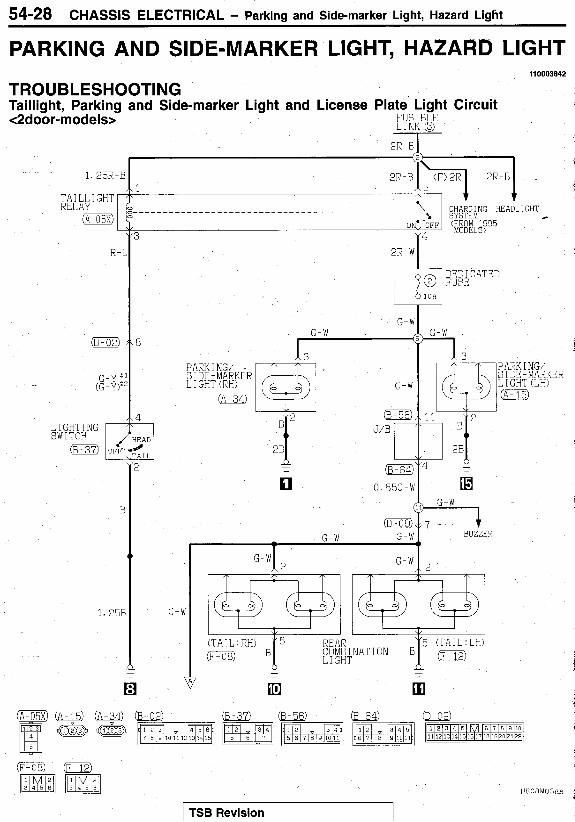
PARKING AND SIDE-MARKER LIGHT, HAZARD LIGHT
TROUBLESHOOTING Taillight, Parking and Side-marker Light and License Plate Light Circuit <2door-models>
I10003642
FUSIBLE LINK 8
1. 25R-B I \ 1 " TA I LI, I GHT
R E L A Y
"I -OFF (f1!&@5 4
!
PARK I NG/ SIDE-MARKER L I GHT (LH) m
G-W
G-W G-W
- G-W
,\ 2 4 1
-
COMBINATION REAR LIGHT
1.2% G-W
BUZZER
I TSB Revision I

CHASSIS ELECTRICAL - Parking and Side-marker Light, Hazard Light 54-29
G
E
c B
- 1. 258
!OTC 1 : 1593 MODELS.
12: F O R M 1954 MODELS.

54-30
<4-door models>
CHASSIS ELECTRICAL - Parking and Side-marker Light, Hazard Light
R - L I
0
2R-V
I
i
+ G-V
G - 12'
(864: -
0 0. 85G-V
0
G-W G-W
G-h - G-W
2 REAK COMBINATI3N LIGIIT
2 -,Ii#
1 3 P A R K I KG/ 5 I DE -MARKER L I GHT {LH) 0
m 3 BUZZER
1
G W

-
CHASSIS ELECTRICAL - Parking and Side-marker Light, Hazard Light 54-31
REAR SIDE- MARKER L I GHT (RH)
G-I
G-\
,1: I
B
B
1. 258
G-W
1cF-os)
G
9
- !OTE - 1 : 1Y93 MODELS. ":FROM 1994 MODELS.

54-32 CHASSIS ELECTRICAL - Parking and Side-marker Light, Hazard Ligtit
OPERATION TROUBLESHOOTING HINTS <Taillight, Parking / Side-marker light, License plate light operatiom 1) The headlights also do not illuminate.
When the lighting switch is set to the “TAIL” or “HEAD position, electricity flows via dedi- cated fuse No. 2 to each light, and each light illuminates.
1. All lights do not illuminate.
2) The headlights illuminate. Check fusible link No. 3
0 Check dedicated fuse No. 2
COMPONENT LOCATION
I Tailliaht relav ’ Enaine I I coipartment I //I’ ?> relav box .

CHASSIS ELECTRICAL - Parking and Side-marker Light, Hazard Light 54-33 OPERATION <Turn-signal light> 1. In normal operating condition
When the ignition switch is placed in the ON position, battery voltage is applied through the hazard switch to the turn-signal and hazard flasher unit. When the turn signal switch is turned to the “LH” or “ R H position, the relay contact turns “ON” and “OFF” repeatedly due to the switching operation of the condenser and transistor inside the flasher unit, and the turn signal light and the “LH” and “RH” of the turn signal indicator light flash.
When either one of the turn signal lights is burnt, the resistance of the entire light circuit increases, so that the time required for charging and discharging of the con- denser is shortened, causing the “ON” “OFF cycle of the relay to become faster than normal and the number of flashes to increase.
<Hazard-warning lights>
2. When one bulb is burnt
When the hazard-warning switch is switched to the “ON” position, the relay contact of the flasher unit is switched ON and OFF repeatedly, in the same manner as for the operation of the turn-signal lights, and the left and right turn- signal lights and turn-signal indicator lights si- multaneously flash repeatedly. NOTE The number of flashes of the hazard-warning lights does not change if there is damaged or disconnected wiring of one light.
COMPONENT LOCATION
TROUBLESHOOTING HINTS 1. The turn-signal lights and hazard-warning lights
do not operate at all. Check the hazard-warning switch contact (power supply side).
0 Check the flasher unit. 2. All turn-signal lights at the left (or right) side
do not function. 1) The hazard-warning lights function normal-
ly. Check the hazard-warning switch con- tact (turn-signal side). Check the turn-signal switch.
3. Turn-signal lights continue to illuminate. Check the bulbs.
4. The hazard-warning lights do not function. 1) The turn-signal lights function normally.
Check the hazard-warning switch con- tact (hazard-warning light side).
I
Turn signal and hazard flasher unit

54-34
Turn-signal Light and Hazard Light Circuit
CHASSIS ELECTRICAL - Parking and Side-marker Light, Hazard Light
TAIL REL!
2R-W
DEDICATED FUSE
G-W
TAILLIGHT, PARKING AND SIDE-MARKER LIGHT AND LICENSE PLATE LIGHT
G-W
m G-W
,AUTO-CRUISE .CIGARETTE 'REAR
CONTROL SYSTEM LIGHTER WINUUW DEFOGGER G-W
HAZARD SWITCH L
I GHT -
7
1
IGNI' SWITl -
2B-W
I "-:I 2B-W
10A
1 . A I R CONDITIONING SYSTEM .HEATER .METER AND GAUGES
0. 85B-W B-W *
3
) I L L
~
10
BATTER FJSIBL
R-I
R-f
E-E
LINK 0
DEDICATED FUSE 7
10 m
11
F

CHASSIS ELECTRICAL - Parking and Side-marker Light, Hazard Light 54-35
h A Z A R D SWITCH .3-SPEED . P I R CONDITIONING SYSTEM
i iAZARD SW I T C H AUTOMAT1 C TRANSAXLE
.AUTO-CRUISE . E X 4-SPEED CONTROL SYSTEM AUTOMATIC TRANSAXLE
J/B
G-W
I:
.CIGARETTE LIGHTER .HEATER
.REAR WINDOW .METER AND GAUGES DEFOGGER .RADIO AND TAPE. PLAYER
3 J/B TURN S I G N A L
AND HAZARD F L A S H E R U N I T
B-k
0 0
Y
G-L R H E O S T A T (MECHANICAL TYPE) 0
I C l U COME I NAT METER m
R H E O S T A T TYPE) L (ELECTRONIC
0
d NOTE II 1 1993 MC3ELS Z2.FROM 1994 MODELS.
- , -
H

54-36
Turn-signal Light and Hazard Light Circuit (Continued)
CHASSIS ELECTRICAL - barking and Side-marker Light, Hazard Light
TURN SIGNAL SWITCH
H M A R D SW I "CE
G-L G-E
0
1
_ ~ -
G-R
3
1 . e5G-1 0. 85G-L G-L
FRONT TURF SIGNAL L I GHT (LH) 0 i
E
2E
;1 REAR ; , COMBINATION . L I GHT (RY)
1 I E
i I
YDTE %2:FROM 1934 MODELS. *1:19'33 MDDCLS. - El
HEOQMOOBP
TSB Revision

CHASSIS ELECTRICAL - Parking and Side-marker Light, Hazard Light 54-37
PARKING AND SIDE-MARKER LIGHT, HAZARD LIGHT REMOVAL AND INSTALLATION I10003643
<Front Turn-signal Light>
4 A b b B 4 1. Front turn-signal light
/
~
,’ <Hazard Light Switch>
3
A16S0727
2
Removal steps 2. Knee protector
4 B b b A 4 3. Air outlet center panel assembly 4. Switch holder 5. Hazard light switch
REMOVAL SERVICE POINTS +AP FRONT TURN SIGNAL LIGHT REMOVAL Remove the set spring, and pull the front turn signal light forward to remove it.
I TSB Revision

54-38 CHASSIS ELECTRICAL - Parking and Side-marker Light, Hazard Light
position
OFF
z19soo90
1 2 3 4 5 6 7 8 9 10
e-a C+-@-O
Z20S015
4 B b A I R OUTLET CENTER PANEL ASSEMBLY
(1) Remove the cool air bypass lever cable of the air outlet center panel assembly at the heater unit side.
(2) Remove the air outlet center panel assembly mounting screws, and remove the air outlet center panel assembly.
REMOVAL
INSPECTION Hazard Light Switch Operate the switch and check for continuity between the termi- nals.
I Switch I Terminal No.
Illumination light I
INSTALLATION SERVICE POINTS .A4 AIR OUTLET CENTER PANEL ASSEMBLY
(1) Install the air outlet center panel assembly to the instrument
(2) Turn the cool air bypass lever of the air outlet center panel
INSTAL LATlO N
panel.
assembly fully upward (in the direction of the arrow).
(3) Turn the cool air bypass damper lever at the heater unit side fully downward (in the direction of the arrow), and install the cool air bypass lever cable.
b B 4 FRONT TURN SIGNAL LIGHT INSTALLATION (1) After aligning the positioning boss of the front turn signal
light with the fender insertion hole, align the ribs with the headlight insertion holes.
(2) While pressing in the front turn signal light towards the rear of the vehicle, hook the set spring to the fender shield inner to secure the front turn signal light to the vehicle body.
I
TSB Revision
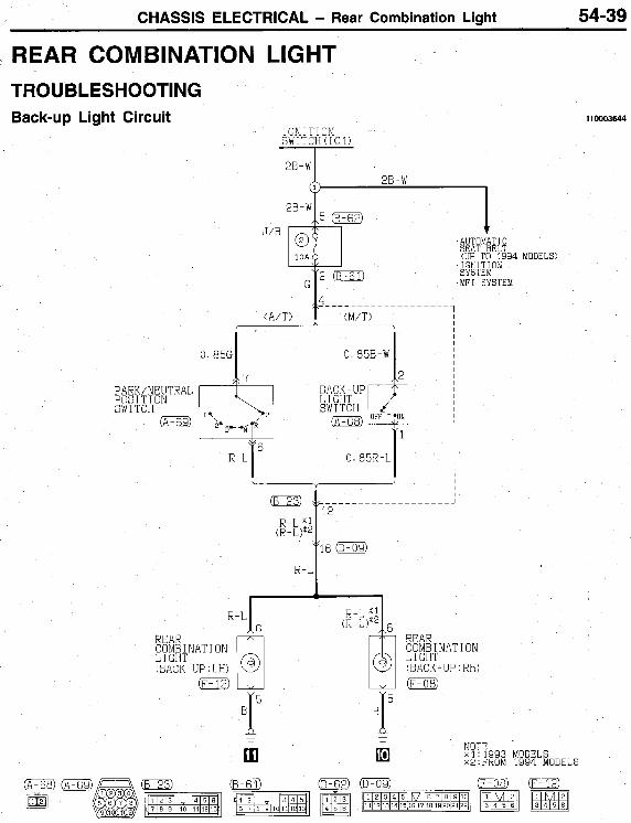
CHASSIS ELECTRICAL - Rear Combination Light 54-39
REAR COMBINATION TROUBLESHOOTING Back-up Light Circuit
LIGHT
J/B
IGNI T I ON SWITCH(IG1) I 2B-W I
2B-W 1
PARK/NEUTRAL POSIT1 ON SWITCH 0
0.85G
R-L
0. a5B-W
BACK-UP SWITCH
0.85R-L
f16
110003644
MODELS)

54-40 CHASSIS ELECTRICAL - Rear Combination Liaht
Stop Light Circuit <2-door models>
FUS I BLE L I KK@
AuTr C X J I SF rrrwm WITHOUT CONTROL
0. 85G c; ::
STOP L I CHT SW I TCY ot3
0. 851
(
1
G I n .
15

CHASSIS ELECTRICAL - Rear Combination Light 54-41
Stop Light Circuit c6door models>
TUS I BLE L I NK@ I
WITHOUT CONTROL
v
0. 85R-W 0. 85R-W
T Q
NOTE -
$ 2 kROM 1994 MODELS
-
1 1993 MODELS
NO CONNECTION mx4
REAR COMB I NAT I ON L I GHT (STOP : RH)
54-42 CHASSIS ELECTRICAL - Rear Combination Liaht
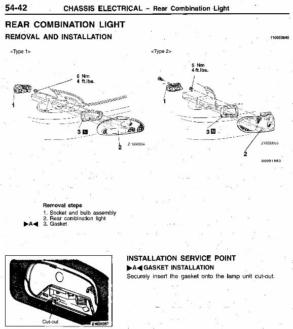
REAR COMBINATION LIGHT REMOVAL AND INSTALLATION 110003645
<Type 1 > <Type 2>
5 Nrn 4ft.lbs.
5 Nm
2 00001 563
Removal steps 1. Socket and bulb assembly 2. Rear combination light
F A + 3. Gasket
INSTALLATION S ERVlC E POINT F A 4 GASKET INSTALLATION Securely insert the gasket onto the lamp unit cut-out
CHASSIS ELECTRICAL - High Mounted Stop Light 54-43
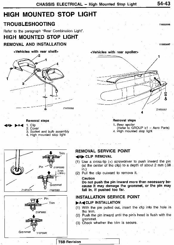
HIGH MOUNTED STOP LIGHT TROUBLESHOOTING
HIGH MOUNTED STOP LIGHT Refer to the paragraph “Rear Combination Light”.
REMOVAL AND INSTALLATION
<Vehicles with rear shelf> /2
Removal steps
2. Cover 3. Socket and bulb assembly 4. High mounted stop light
+ A F F A 4 1. Clip
Zi9POO71 Z19POO81
Trim
z1 BP0082
110003646
110003647
<Vehicles with rear spoiler>
/ 21 650057 4
Removal steps 1. Rear spoiler
(Refer to GROUP 51 - Aero Parts) 4. High mounted stop light
REMOVAL SERVICE POINT 4 A F CLIP REMOVAL (1) Use a cross-tip (+) screwdriver to push inward the pin
(at the center of the clip) to a depth of about 2 mm (.08 in.)
(2) Pull the clip outward to remove it. Caution Do not push the pin inward more than necessary be- cause it may damage the grommet, or the pin may fall in, if pushed too far.
INSTALLATION SERVICE POINT F A 4 CLIP INSTALLATION (1) With the pin pulled out, insert the clip into the hole in
(2) Push the pin inward until the pin’s head is flush with the
(3) Check whether the trim is secure.
the trim.
grommet.
I
rTSB Revision
54-44 CHASSIS ELECTRICAL - Interior Liaht
- I
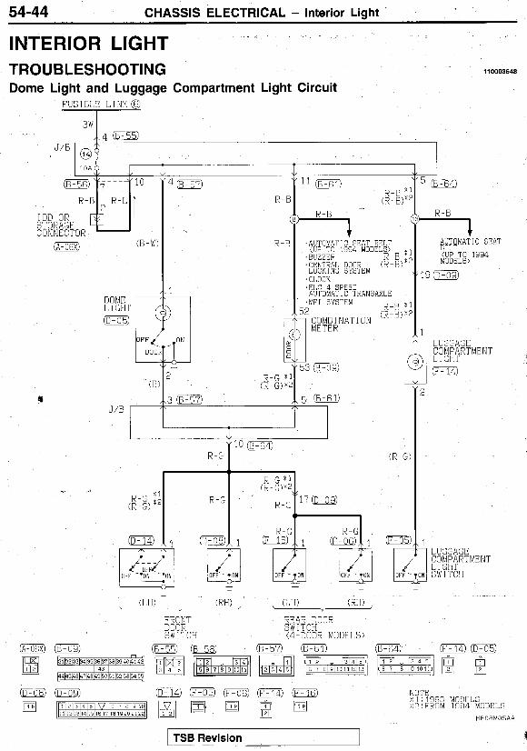
INTERIOR LIGHT TROUBLESHOOTING 110003648
Dome Light and Luggage Compartment Light Circuit FUSIBLE LINKG
A V IOD OR STORAGE CONNECTOR 0 (B-W)
I , I G H T 0
J/B
,AUTOMATIC SEAT BELT (UP TO 1994 MODELS) *
'BUZZER R - B 'CENTRAL DOOR (R-B) R-B I LOCKING SYSTEM . C l . f l C K .ELC 4-SPEED I AJTOMATIC TRANSAXLE
1 AUTOMATIC SEAT BELT (UP TO 1994 MODELS)
19 (D-OS)
LUGGAGE
~ - (LH) (RH) (LH) (RH)
FRONT REAR DOOR DOOR SWITCH SWITCH (4-300R MODELS)
L- i- ,
gOTE n>l: 1993 MODELS ":FROM 1934 MODELS
HEOBMOSAA
I TSB Revision

CHASSIS ELECTRICAL - Interior Light 54-45 OPERATION <Dome light> 0
0
The dome light is always illuminated when the dome light switch is at the “ON” position. The dome light illuminates when any door is opened while the dome light switch is at the “DOOR” position. The dome light switches OFF when all doors are closed.
Battery voltage is always applied (via fusible link No. 6 and multipurpose fuse No. 14) to the luggage Compartment light.
0 When the trunk lid is opened, the luggage Compartment light switch is switched ON and the luggage compartment light illuminates.
0
<Luggage compartment light> 0
TROUBLESHOOTING HINTS 1. The dome light does not illuminate.
1) The clock is stopped also. 0 Check multipurpose fuse No. 14.
2) The dome light does not illuminate when, with the dome light switch at the “DOOR” position, any door is opened. 0 Check the bulb. 0
3) The dome light does not illuminate when, with the dome light switch at the “DOOR” position, a certain door or doors islare opened. 0 Check the door switch [the door
switch(es) for the door(s) that does not activate the dome light when opened].
2. The luggage compartment light does not illumi-
Check the dome light switch.
nate. 1) The dome light is normal.
0 Check the bulb. 0 Check the luggage compartment light
switch.
54-46 CHASSIS ELECTRICAL - Column Switch
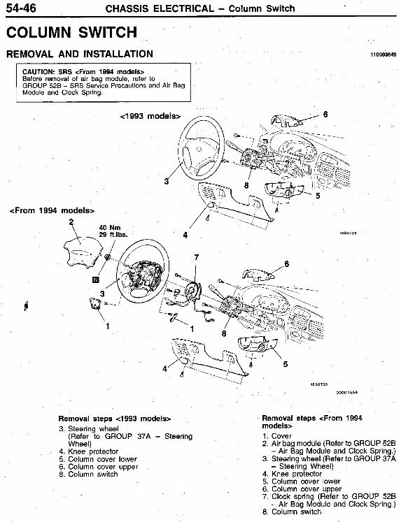
COLUMN SWITCH REMOVAL AND INSTALLATION
I
HOW3649
CAUTION: SRS <From 1994 modelsr Before removal of air bag module, refer to GROUP 528 - SRS Service Precautions and Air Bag Module and Clock Spring.
<From 1994
Removal steps 4993 models> 3. Steering wheel
(Refer to GROUP 37A - Steering Wheel)
4. Knee protector 5. Column cover lower 6. Column cover upper 8. Column switch
Removal steps <From 1994 models> 1. Cover 2. Air bag module (Refer to GROUP 52B
- Air Bag Module and Clock Spring.) 3. Steering wheel (Refer to GROUP 37A
- Steering Wheel) 4. Knee protector 5. Column cover lower 6. Column cover upper 7. Clock spring (Refer to GROUP 526
- Air Bag Module and Clock Spring.) 8. Column switch

CHASSIS ELECTRICAL - Column Switch 54-47
Connector A
Z16SO315
Wl Connector B
21 6.50308
INSPECTION Operate the switch and check for continuity between the termi- nals.
Switch position
LIGHTING I OFF
DIMMER/ PASSING
TURN SIGNAL
PASS- f OFF
Terminal No.
Connector A I Conngector
WIPER AND WASHER SWITCH Refer to GROUP 51 - Windshield Wiper and Washer.

54-48 CHASSIS ELECTRICAL - Rheostat
RHEOSTAT <
REMOVAL AND INSTALLATION I10003650
<Mechanical type> <Electronic type>
,
690540
5 21 650529
00001565
Removal steps <Mechanical types 1. Garnish
3. Ring nut 5. Rheostat
Q 2. Knob
Removal steps <Electronic type> 4. Air outlet panel assembly 5. Rheostat
INSPECTION <Mechanical type> (1) With the connector disconnected, measure the continuity
between the rheostat terminals with an ohmmeter. (2) If the resistance value varies smoothly between 0 and
10 ohms throughout the entire operation range, the rheo- stat is functioning properly.

CHASSIS ELECTRICAL - Rheostat 54-49
<Electronic type>
21 650307
Connect the battery and the test bulb (40W) as shown in the illustration. Operate the rheostat, and if the brightness changes smoothly without switching off, then the rheostat function is normal.

54-50 CHASSIS ELECTRICAL - Buzzer
BUZZER TROUBLESHOOTING
BUZZER REMOVAL AND INSTALLATION llWW652
Refer to the paragraph “Parking and side-marker light, hazard light”.
1
Removal steps B 1. Knee protector
3. Radio and tape player 4. Cup holder 5. Buzzer
4 A b F A 4 2. Air outlet center panel assembly
\ / z19soo9
110009651
A 1 6 0 7 3 3
REMOVAL SERVICE POINT A A b AIR OUTLET CENTER PANEL ASSEMBLY
(1) Remove the cool air bypass lever cable of the air outlet center panel assembly at the heater unit side.
(2) Remove the air outlet center panel assembly mounting screws, and remove the air outlet center panel assembly.
REMOVAL

CHASSIS ELECTRICAL - Buzzer 54-51
Z16C035:
0 -
*# F IP INSPECTION LIGHTING MONITOR BUZZER (1) Apply battery voltage between the terminals 2, 8 and 10. (2) Check to be sure that the buzzer sounds when terminal
3 is grounded.
INSTALLATION SERVICE POINT FA+ AIR OUTLET CENTER PANEL ASSEMBLY
INSTALLATION (1 ) Install the air outlet center panel assembly to the instrument
(2) Turn the cool air bypass lever of the air outlet center panel panel.
assembly fully upward (in the direction of the arrow).
(3) Turn the cool air bypass damper lever at the heater unit side fully downward (in the direction of the arrow), and install the cool air bypass lever cable.

54-52 CHASSIS ELECTRICAL - Horn
0 . E5G-B
0. E 5 G - B
HORN TROUBLESHOOTING
-
;?12 0
110003653
CIRCUIT DIAGRAM el993 models> I G N I T I f l N SWITCH(ACC)
WITHOUT AUTO-CRUISE CONTROL
0 COLUMN SWITCH
G-B
STEERING WHEEL ASSEMBLY
SWITCH

CHASSIS ELECTRICAL - Horn 54-53 CIRCUIT DIAGRAM 4 9 9 4 models>
IGNITION ~
L
G-B
G-R
i. G-R
J/B / @
0.85L \
ITCH (ACC)
HORN RELAY 0
I 0. 85B
2E
C. 85B I
0

54-54 CHASSIS ELECTRICAL - Horn
CIRCUIT DIAGRAM <From 1995 models> C r
L
G-F
r-
G-E
0
G-E
m G-I;
IGNITION S W I T C H ( A C C ) I
CLOCK
9 - I J/B

CHASSIS ELECTRICAL - Horn 54-55
COMPONENT LOCATION
Horn relay 4 9 9 4 models> 1 <-,-
HORN REMOVAL AND INSTALLATION
I Horn relav <From 1995 models>
Z1680297
Removal steps 0 Headlight (Refer to P.54-26.) 1. Horn
NOTE Remove the horn at the L.H. side by the same procedure.
Z1680297

54-56 CHASSIS ELECTRICAL - Horn
1
I 4994 models>
2 1. 3 4
--1
Not applied
Applied
+a 1 3
0 0 0 0 0 0
l 8 W 0 3 5 0 I <From 1995 models>
I 2 0 W 0 2 0 6 00001 566
INSPECTION HORN RELAY (I) Remove the horn relay. (2) Check for continuity between the terminals. el994 models>

54-58 CHASSIS ELECTRICAL - Cigarette Lighter
CIGARETTE LIGHTER TROUBLESHOOTING CIRCUIT DIAGRAM
IGNI' SWIT(
2L
J'B
0.S5L
C I G A R E T T E
L .AUTD-CRUISE .REAR WINDOW CONTROL SYSTEM DEFOGGER 0. 8% v I (B-Y)
REAR WINDOW AUTO-CRUISE- DEFOGGER CONTROL SYsiEV
1 1 I 0.85E
0.85E
J/E - 28
IN (ACC)
TAIL LAMF - 2R-'
DED I GATED
G-1
G-\
(G-W) ic-os)
C-08 IN
G - \ ' 3-SPEFD AU I UMATI C TRANSAXLE AIR CCNDITI ONING SYSTEM AUTDMfiT I C TRANSEXLE . HEATER (G-W .METER AND GAUGES 'TURN-SIGNAL LIGHT AND HAZARD LIGHT TAPE PGfiYER
.ELC 4-SPEED
. RADIO AND
I(B58: 1 I B-k
110003655
I GHT i E L A Y
1 TAILLIGHT, PARKING AND
1 PLATE LIGHT 11 0 E g p ~ ~ ; E E I C E N S E
ASHTRAY 9 ~u!! I NAT I ON C- 14
I (A)
- RHEOSTAT 0
AUT CON REA DEF
lRUISE IL SYSTEM :INDOW rE R

CHASSIS ELECTRICAL - Cigarette Lighter 54-59 _ _ _ ~
CIGARETTE LIGHTER REMOVAL AND INSTALLATION
i
110003656 * 1
Removal steps 1. Plug 6. Fixing ring 2. Radio and Tape player 3. Cup holder 4. Cigarette lighter illumination light 5. Cigarette lighter power supply 10. Socket
7. Ground connector 8. Socket case 9. Plate
connector 11 . Protector
INSPECTION 0 Take out the plug, and check for a worn edge on the
element spot connection, and for shreds of tobacco or other material on the element. Using an ohmmeter, check the continuity of the element. 0
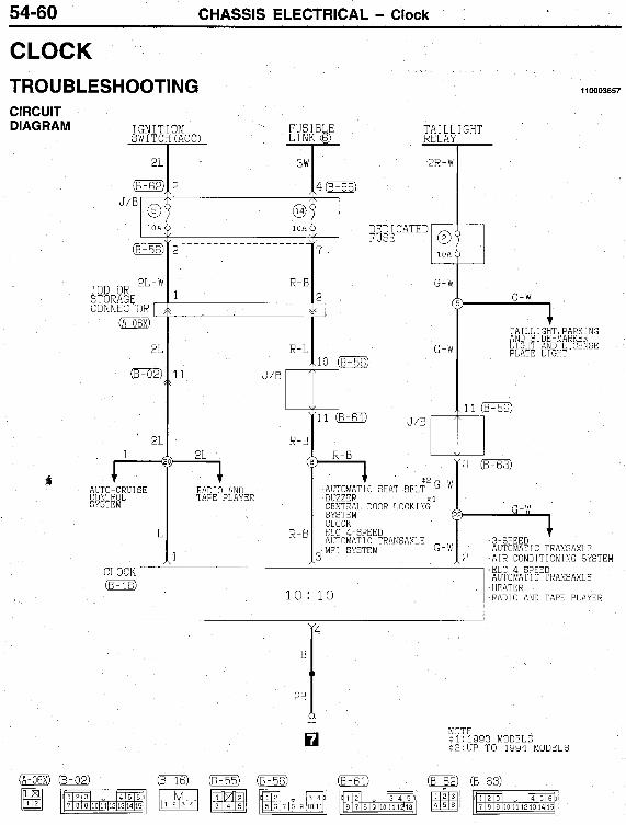
54-60 CHASSIS ELECTRICAL - Clock
CLOCK TROUBLESHOOTING CIRCUIT DIAGRAM IGNI ' I
SW I TC
2L
(B-62:
(B-56:
IOD 2L-iz
CONNECTOR r S T 0 RAGE
0
8 2L
' AUTO-CRUISE CONTROL SYSTEM
L
CLOCK ml-
3\
10f
R - I
J'B c 1
R-E
1 RAnig AWD- TAFE FLAY-R
2-€
LE EL
(8-55)
1 1
I10003657
TAI LL IGHT RELAY
2R-W
D i D I C A T E D E FUSE
G-W
G-W 0 0 1
I 1
J'B I 1 0
R-B I 1 + *2 G-W .AUTOMATIC SEAT BELT 'BUZZER :I ,CENTRAL DOOR LOCKING SYSTEM ( ,CLOCK ,FLC &SPEED 'MF! SYSTEM G-W AUTOVATIC TRANSAXLE
10: 10
1
i
1 'TAIL& IGHT, PARKING AND 3IDE-MARKER LIGHT AND LICENSE PLATE LIGHT
11 m
-1
1 .S-SPEED AUTOMATIC TRANSAXLE
? .AIR CONDITIONING SYSTEM .ELC 4-SPEED AUTOMATIC TRANSAXLE 1 .HEATER I .RADIO AN0 TAPE FLAYEK

CHASSIS ELECTRICAL - Clock 54-6 1
CLOCK REMOVAL AND INSTALLATION llWIM658
$ -L
7 - -
i--
I , ,
Amson?
Removal steps 1. Knee protector 2. Air outlet center panel assembly (Refer +e 4. Clock
3. Radio and tape player
to P.54-38.)
REMOVAL SERVICE POINT + A F CLOCK REMOVAL (1) Remove the heater control assembly mounting screws.
(2) Remove the heater control assembly boss from reinforcement (L.H.).
center
(3) Push the heater control assembly into the instrument panel, remove the clock mounting screws, and remove the clock.
I TSB Revision I

54-62 CHASSIS ELECTRICAL - Radio and Tape Player
RADIO AND TAPE PLAYER TROUBLESHOOTING CIRCUIT DIAGRAM 4 9 9 3 MODELS
IGNITION SWITC+:ACC) FUB I BLE
2L
2 L - w
IOD OR STORAGE CONNECTOR 0
2 L
21
t <
2L
\
(A-06X) (8-02)
3w !O
@ 1 OA
R - B
I
2-B
( i 3 AUTO-CRUISE ' CLOCK CONTROL SYSTEM
R-B
TAIL LINK @ RELA
2R-W
-
1 0 DEDICATED FIJSE 1
7 0
G-W
G-W
10
1 AUTO-CRUI SE CONTROL SYSTEM
G-W
' CLOCK ' HEATER
G-W -
7
110003659
SPT
1
r ,-w
-P. ILL I GHT SIDE-MARKER -1GH'I AND LICENSE PLkTE LIGHT
PARK I NG AND
' 1 0
1 TURN-SIGNAL LIGHT AUTO CRUISE AND HAZARD LIGHT CONTROL SVSTEM
' C I GA'ZETTE L I GHTER DEFOGGER
1 .3-SPEED AUTOMAT I C -RANSAXLE .AIR CONDITIONING SYSTEM 'ELC 4 SPEED AUTOMATI TRANS AXLE
~ ~ I ~ ~ ' @ J f p & J q 7 0 9 101112331415 3 4 5 5 6 7 8 9 1011 7 0 9 101112131415

CHASSIS ELECTRICAL - Radio and Tape Player 54-63
G-1
I
AUTO-CRUISE CIGARETTE L IGHrER DEFOGGER
B-Y (ELECTRONIC I (MECHANICAL TYPE) ~ TYPE)
I I I I I I I I
I I I I I L.
w-L
RADIO AND TAPE PLAYER
(LH)
Y-R
1
CR-T;
(RH) (LH)
-
10
Y-I;
3
I
4.~00~
'? (D-os: MODELS
)
0
. -
FRONT SPEAKER R F A R SPEAKER
HE14M02AB
TSB Revision

54-64 CHASSIS ELECTRICAL - Radio and Tape Player
CIRCUIT DIAGRAM 4 9 9 4 MODELS
IGNI' SW I TI
21
-
2L-I
IOD OR STORAGE [ CONNECTOR 0
21
21
21
IN ACC) FUS I EL -
311 m
R - I
R - I
i ' AUTO-CRU'SE ' CLOCS CCNTWL SYSTZM
(B-63
R-I
R-I
TAIL RELA -
G-W
( 1
G- w n I J
1 AUYO-CRUISE CONTROL SYSTEM G-W
' CLOCK ' HEATER
G-W
GHT
1 1
11
TURN-SIGNAL LIGHT AUTO-CRUISE AND HAZARD LI2HT CONTROL SYSTEM
, C!CARETTE LIGHTER
' REAR UEFOGGER w I m w
1 .3-SPEED AUTOMAT I C TRANSAXLE SYSTEM AUTOMAT I C TRANS AXLE
'AIR CONDITIONING 'ELC 4-SPEED

CHASSIS ELECTRICAL - Radio and Tape Player 54-65
rt
G-
RADIO AND TAPE PLAYER
B-I
1
6-R
1
1
G E L
Y - I ,
3
5 (B-2Sl
GR-R I- _ _ _ _ _ _ _ _ _ _ 2
(LH) (RH) .- Y-
FRONT SPEAKER REPR SPEAKER
HE 14M03AB
I TSB Revision

54-66 CHASSIS ELECTRICAL - Radio and TaDe Plaver
CIRCUIT DIAGRAM <FROM 1995 MODELS>
I G N I l SW I TC
2L
2 L - w
IOD OR STORAGE [ CONNECTOR
m 2 L
2 L
I
2L
IN (ACC) FUS I BLE
3w
-
? -
@ 10A
?
R-B
R-L
c ' 1 0
R - E
L 1
. AUTO-CRUISE CONTROL SYSTEM
. CLOCK
R-E
1
TAIL L I N K 8 RELL -
G-V
il G-V
1
AUTO-CRUISE CONTROL SYSTEM
G - \
, CLOCK ' HEATER
G-V
GHT
1 TAILLIGHT,
LIGHT AND LICENSE PLATE 1,IGHT ;:$g!;gR;gg
'1-
G-W
(G-W)
G - w TURN SIGNAL LIGHT , AUTO-CRUISE 17: LIGIITER DEFOGGER WINDOW AND HAZARD LIGHT CONTROL SYSTEM
' CIGARETTE
1

CHASSIS ELECTRICAL - Radio and Tape Player 54-67
. T
I I ,3-SPEED AUTOMATIC L TRANSAXLE CONDITIONING SYSTEM AUTOMAT I C TRANSAXLE
.AIR
,ELC 4-SPEED E-Y
1 (B-Y) ~
I B-Y AUTO CRUISE CONTROL SYSTEM C I GARETTE L 1 GHTER
' REAR WINDOW B-Y DEFOGGER
1 (B Y) ~
E-Y
12
w-L
12 0 TURN-SIGNAL LIGHT ;AN: -HiZAr LIGHT
:MECHANICAL TYPE) 7
, p ,,3
\I
0 "2
I 1
om2
RHEOSTAT
0 - (T. F
w-L
I l l
KADIO AND TAPE PLAYER
6
B-
V-R
Y-L
2 m
Y-L
3
GR-1
1
3
GR-F
- Y I
FRONT SPEAKER REAR SPEAKER
l iE14M05AB
I TSB Revision I

54-68 CHASSIS ELECTRICAL - Radio and Tape Player
Problem symptom
TROUBLESHOOTING CHART Relevant chart Item
1. No sound.
2. No sound from one speaker. -
A. Noise
B-1
B-2
B. Radio
8. Too few automatic select stations.
9. Insufficient memory (preset stations are erased).
1. Cassette tape will not insert.
4
B-8
5-9
c-1 C. Cassette player
3. No sound from one speaker.
4. Sound quality is poor, or sound is weak.
5. Cassette tape will not eject.
c-3
c -4
c-5
1. Noise appears at certain places when traveling (AM).
2. Noise appears at certain places when traveling (FM).
3. Mixed with noise, only at night (AM). A-3
7. Automatic search does not work (only for models with automatic search function).
~ -~ -
8. Faulty auto reverse.
9. Tape gets caught in mechanism.
4. Broadcasts can be heard but both AM and FM have a lot of noise. 1 A-4
C-7
- _ _ C-8
c -9
5. There is more noise either on AM or on FM. I A-5
6. There is noise when starting the engine.
7. Some noise appears when there is vibration or shocks during traveling. ~-
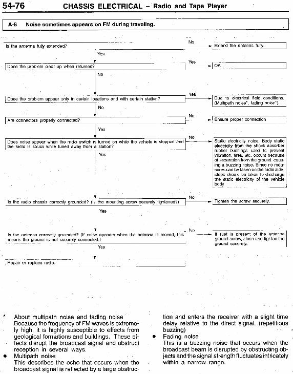
8. Noise sometimes appears on FM during traveling. 1 A-8
9. Ever-present noise. I A-9
3. There is noise but no reception for both AM and FM. I 8-3
4. No sound from AM, or no sound from FM. I 8-4
5. Insufficient sensitivity.
6. Distortion on AM or on both AM and FM.
7. Distortion on FM only.
2. No sound. 1 c -2
6. Uneven revolution. Tape speed is fast or slow. I C-6

CHASSIS ELECTRICAL - Radio and Tape Player 54-69
CHART A. NOISE
1 A-1 Noise appears at certain places when traveling (AM). I
Is there a particular structure? I 1. Change to a different station with a strong
sianal to boost resistance to interference.
Find out the following information from the user:
2 3. Extend antenna completely.
Sippress high tones to reduce noise.
1 Place 2. Locality conditions (valley, moun-
tain, etc ) 3. Name and frequency of stations
affected by noise Yes
OK Inspect the vehicle's noise suppressor (refer to A-6).
1 If due to vehicle noise: It may not be possible to prevent noise if the signal is weak.
1 cases, prevention on the receiver side is impossible. Weak signals especially
If there is more noise than other radios, find out the noise conditions and the name and frequency of the receiving stations from the user, and consult with the service center.
1

54-70 CHASSIS ELECTRICAL - Radio and Tape Plaver
Do the following measures eliminate the noise? 0 Change to a different station with a strong signal to boost resistance to interference. 0 Suppress high tones to reduce noise. 0 Extend antenna completely.
~~
yes
NOTE as mountains or buildings, interference of the About FM waves: FM waves have the same properties as light, and can be deflected and blocked. Wave recep- tion is not possible in the shadow of obstructions such as buildings or mountains. The signal becomes weak as the distance from the station’s transmission antenna increases. Although this may vary according to the signal strength of the transmitting station and interven- ing geographical formations or buildings, the area of good reception is approx. 20-25 km (12-16 miles) for stereo reception, and 30-40 km (19-25 miles) for monaural reception. The signal becomes weak when an area of shadow from the transmitting antenna (places where there are obstructions such as mountains or buildings between the antenna and the car), and noise will appear. <This is called first fading, and gives a steady buzzing noise>. If a direct signal hits the antenna at the same time as a signal reflected by obstructions such
two signals will generate noise. During traveling, noise will appear each time the vehicle’s anten- na passes through this kind of obstructed area. The strength and interval of the noise varies according to the signal strength and the condi- tions of deflection. <This is called multipath noise, and is a repetitious buzzing>.
4. Since FM stereo transmission and reception has a weaker field than monaural, it is often accompanied by a hissing noise.
5. Ordinary vehicles are more susceptible to these types of interference than vehicles equipped with an FM diversity antenna system. If the problem vehicle is identical to a vehicle (radio) of the same type, the variation may be due to different antenna systems. FM diversity an- tenna system: Two types of antennas (whip or motor antenna and glass antenna) are used. This system allows selection of the antenna that gives the best reception.
FM sianal ch FM broadcast good reception areas . . . . - and signal interference
..~ .. .aracteristics
I (19-25 miles) I 11 For monaural: 30-40 km . h l a 07 I
. . . . ’ For home stereos 80-90 km
Z16A0664 (50-56 miles) Z16A0663

CHASSIS ELECTRICAL - Radio and TaDe Plaver 54-71
I A-3 Mixed with noise, only at night (AM).
The following factors can be considered as possible causes of noise appearing at night. 1. Factors due to signal conditions: Due to the
fact that long-distance signals are more easily received at night, even stations that are received without problem during the day may experience interference in a general worsening of reception conditions. The weaker a station is the more susceptible it is to interference, and a change
to a different station or the appearance of a beating sound* may occur.
Beat sound: Two signals close in frequency interfere with each other, creating a repetitious high-pitched sound. This sound is generated not only by sound signals but by electrical waves as well. .
2. Factors due to vehicle noise: Alternator noise may be a cause.
tenna.
ground wire mounting area Mount the antenna secure-
Do the following measures eliminate the noise? 0 Tune to a strong station 0 Tune to a station with a strong signal
without comoletely extending the 1 OK I I antenna. I I (reier to A-6). No
1 Is the noise eliminated? 1
t Does the following measure eliminate the noise? 0 Move the harness on the vehicle
side away from the radio body (If the harness is not In the proper posi- tlon).
No
I
1 If there is more noise than other radios, consult a service center.
I
No

54-72 CHASSIS ELECTRICAL - Radio and Tape Player
I Noise occurswhen the engine is stopped
I A-4 Broadcasts can be heard but both AM and FM have a lot of noise. I
Noise occurs when the engine in running

CHASSIS ELECTRICAL - Radio and Tape Player
I A-5 There is more noise either on AM or on FM. I 1. There is much noise only on AM
Due to differences in AM and FM systems, AM is more susceptible to noise interference.
such as the following present when noise was received? 0 Lightning was flashing. A motorcycle was passing
A vehicle passed close by, but it appeared to be a vehicle generating a particularly large amount of noise radiation Passed beneath a power line. Passed under a bridge Passed beneath a telephone line. Passed close by a signal generator Passed close by some other source of electrical noise.
Yes
No
isdifficult lfthe problem is particular- ly worse than other radios, consult
1 Continue to check for static; when static is Ltected, check for the conditions listed above 1 No
If the problem is particularly worse than other radios, consult a service center
2. There is much noise only on FM a) Due to differences in FM and AM systems, FM
is not as susceptible as AM to interference from engines, power lines, lightning, etc. On the other hand, there are cases due to the character- istics of FM waves of noise or distortion gener- ated by typical noise interference (first fading and multipath). (Refer to A-2) <Noise (hissing) occurs in weak signal areas such as mountain-
ous regions, but this is not due to a problem with the radio.>
b) Ordinary vehicles are more susceptible to these types of interference than vehicles equipped with an FM diversity antenna system. If the prob- lem vehicle is identical to a vehicle (radio) of the same type, the variation may be due to different antenna systems.

54-74 CHASSIS ELECTRICAL - Radio and Tape Player
I A-6 There is noise when starting the engine.
Noise type Sounds are in parentheses ( ).
AM, FM: Ignition noise (Popping Snapping Cracking Buzzing)
AM, FM: Alternator noise (AM, FM) (Swishing)
AM, FM: wiper mo- tor noise (Low-pitched buzzing Electrical buzzing)
Other electrical components
Static electricity (Crackling Crinkling)
Conditions
~~
0 Increasing the engine speed causing the popping sound to speed up, and volume de- creases.
0 Disappears when the ignition switch is turned to ACC.
Noise becomes higher as en- gine speed increase, and in many cases is not present ai idle speed.
0 Appears with wiper operatior and increases with wiper speed. Disappears when the wipers are stopped.
0
0
Disappears when the vehicle is completely stopped. Severe when the clutch is en. gaged.
0 Various noises are produced de pending on the body part of the vehicle.
Cause
0
0
Mainly due to the spark
Due to the engine noise. plugs.
0 Due to ripples* con- tained in thevoltage pro- duced by the alternator.
0 The amount of fluctua- tion in voltage during full wave rectification of the three phase A.C. current of the alternator is called a ripple.
0 Due to the wiper brushes.
Noise may appear as electri- cal components become older.
Occurs when parts or wiring move for some reason and contact metal parts of the body.
Due to detachment from the body of the front hood, bumpers, exhaust pipe and muffler, suspension, etc.
Response
P Noise filter
P ' Noise condense
P Ground cable
0 Noise condenser
0 Noise filter
Repair or replace
~. ~ _ _ _ Return parts or wiring to their proper position.
Ground parts by bond- ing. Cases where the problem is not elimi- nated by a single re- sponse to one area are common, due to several body parts being imperfectly grounded.
Caution 1. Connecting a high tension cable to the noise
filter may destroy the noise filter and should never be done.
2. Check that there is no external noise. Since failure due this may result in misdiagnosis due to inability to identify the noise source, this operation must be performed.
3. Noise prevention should be performed by suppressing strong sources of noise step by step.
NOTE 1. Condenser
The condenser does not pass D.C. current, but as the number of waves increases when it
oasses A.C. current. imoedance [resistance against A.C.) decreases,' and current flow is facilitated. A noise suppressing condenser which takes advantage of this property is in- serted between the power line for the noise source and the ground. This suppresses noise by grounding the noise component (A.C. or pulse signal) to the body of the vehicle.
The coil passes D.C. current, but impedance rises as the number of waves increases relative to the A.C. current. A noise suppressing coil which takes advantage of this property is in- serted into the power line for the noise source, and works by preventing the noise component from flowing or radiating out of the line.
2. Coil
TSB Revision

CHASSIS ELECTRICAL - Radio and Tape Player 54-75
NOISE SUPPRESSOR MOUNTING LOCATION
-
Ground cable
Ensure proper connection
I
I A-7 Some nolse appears when there is vibration or shocks during traveling. I
~- I Are connectors Drooerlv connected?
1 Yes
appear when the radio switch is turned on while the vehicle is stopped and struck while tuned awav from a station?
Yes
j Yes
ground screw, clean and tighten the Is the antenna correctly grounded? (If noise means the ground is not securely connected.)
1 Yes
1 Repair or replace radio.
54-76
-
CHASSIS ELECTRICAL - Radio and Tape Player
1 Does the problem clear up when returned? - OK
Are connectors properly connected? Ensure proper connection
- j Yes
Due to electrical field conditions
No Static electricity noise Body static electricity from the shock absorber rubber bushings used to prevent vibration, tires, etc occurs because of separation from the ground, caus- ing a buzzing noise. Since no mea- sures can be taken on the radio side, steps should be taken to discharge the static electricity of the vehicle
Does noise appear when the radio switch the radio is struck while tuned away from a station?
I
-
No Tighten the screw securely.
~ ~ I Is the radio chassis correctly grounded? (Is the mounting screw securely tightened?) 1 p - I 1 Yes
ground screw, clean and tighten the
1 No appears when the antenna IS moved, this -I If rust 1s Present of the antenna
means the ground is not securely connected ) 1 ground securely. i Yes
4 -1 I Repair or replace radio
About multipath noise and fading noise Because the frequency of FM waves is extreme- ly high, it is highly susceptible to effects from geological formations and buildings. These ef- fects disrupt the broadcast signal and obstruct reception in several ways. Multipath noise This describes the echo that occurs when the broadcast signal is reflected by a large obstruc-
tion and enters the receiver with a slight time delay relative to the direct signal. (repetitious buzzing)
0 Fading noise This is a buzzing noise that occurs when the broadcast beam is disrupted by obstructing ob- jects and the signal strength fluctuates intricately within a narrow range.

CHASSIS ELECTRICAL - Radio and TaDe Plaver
I Is the key switch of the vehicle in the correct position (ACC OFON)? -
54-77
Perform the correct operation.
A-9 Noise.
Is the volume control adjusted properly? -
Noise is often created by the following factors, and often the radio is OK when it is checked individually. 0
0
0 Surrounding buildings 0 Signal conditions 0 Time period ter.
B. RADIO
For this reason, if there are still problems with noise even after the measures described in steps A-1 to A-8 have been taken, get information on the fac- tors listed at left as well as determining whether the problem occurs with AM or FM, the station names, frequencies, etc., and contact a service cen-
Traveling conditions of the vehicle Terrain of area traveled through
Perform the correct operation
I B-1 Nosound. I
Is there sound when a cassette tape is inserted? Repair or replace radio
Is the connector at the back of the radio connected properly’
With electronicvolume control pressafew seconds in the ‘“up”direction to check.
Connect connector securely
t the vehicle fuses blown (both ACC and BAT)? l-b, Yes Does the problem clear up with fuse I ” - p r l
replacement? + No Is the fuse blown with the connector at the back of the radio discon- v Repairor re-
place radio. 1 nected? I I No
I I Yes t Harness is snagged, or other electri- calparts are faulty 1-1 ness.
Repair har- I

54-78 CHASSIS ELECTRICAL - Radio and Tape Player
Check to see if there is any sound when the radio fader and balance knobs are centered.
I 8-2 No sound from one speaker. I
-1 OK
I Are the antenna plug and radio unit properly connected? , -
Check to see if there is any radio.
Reconnect
speaker harness for conductance.
I Check the speaker for conductance.
4 No I Repair or replace speaker
-1 ReDair or redace radio unit. I
Repair speaker har- I shorted out.
proper connection of relay connec-
B-3 There is noise but no reception for both AM and FM.
No Example, in an underground or in- side a building
+ OK Is proper performance obtained i l when the vehicle is moved?
3
Repair or replace antenna ~~ ~
1 8-4 No sound from AM, or no sound from FM.
Refer to B-3.

CHASSIS ELECTRICAL - Radio and Tane Plaver 54-79
1 Does the problem clear up when returned?
B-5 insufficient sensltlvity
OK
Yes I Is the check beina c o n d l
Is the problem limited to the reception of a specific radio station from a specific position?
I
No Example, in an underground or in- side a buildina I
Electrical field condition related (multi- path noise or fading noise')
Yes + -n IS proper p e t f o i i G Z X G Z
when the vehicle is moved?
Are the antenna plug and radio unit properly connected?
I I
Reconnect
Extend the antenna fully. I
-
c I Is the antenna fully extended?
Remove the speakers and check for torn cone paper or foreign objects Repair or replace speakers
Yes Does the problem disappear if connected to another radio? Repair or replaceradio
No
I Reoair or redace antenna I
* For multipath noise and fading noise problems, refer to page 54-76.
I B-6 Distortion on AM or on both AM and FM

54-80 CHASSIS ELECTRICAL - Radio and Tape Player
Does the distortion persist when the radio is tuned to another station7
I B-7 Distortion on FM only I Due to weak electrical field of radio station
- 1 Does the problem disappear if connected to another radio? ~-
Yes Due to multipath noise
~
c Does distortion increase or decrease when the vehicle is moved? ~-
No
1 Reoair or redace radio
Repair or replace radio
I 8-8 Too few automatic select stations.
Example. in an underground or in- side a building
OK Yes
- I IS rooer I when the vehicle is moved7 I I
Is the antenna fully extended? - Extend the antenna fully
Yes
Is the DWLOC button in the DX position? Place the button in the DX position
yes This item will not apply if the equipment does not have a DWLOC button.
1 Repair or replace antenna

CHASSIS ELECTRICAL - Radio and Tape Player 54-81
B-9 Insufficient memory (preset stations are erased)
Yes
No
b Repair or replace radio of the radio and check for a blown
C. CASSElTE PLAYER
C-1 Cassette tape will not insert.
Yes I Are there any foreign objects in the cassette play& l-wl Remove the object(s)”
Yes Does the cassette player ,peeplace tape *2
1 Repair or replace cassette player 1 NOTE *1 *2 Attempting to force a foreign object (e.g., a coin or clip, etc.) out of the cassette player may damage the mechanism. The player should be taken to a service dealer for repair.
Ensure that the tape label is not loose, that the tape itself is not deformed and that the tape is tightly wound. Also, tapes of C-120 or greater length often get caught in the mechanism and should not be used.

54-82 CHASSIS ELECTRICAL - Radio and Tape Player
Check the position of the ignition switch, ensuring that it IS at ACC or ON.
C-2 No sound (even after a tape has been inserted)
- Try again after correcting.
I Is there any sound when the balance or fader buttons are centered? }--
I C-3 No sound from one speaker
OK
and check again
.Yes Does the radio produce any sound?
L I
_ _ When sound comes from only left or right channel I of the deck
No c 1 Change the tape and check for F-1 OK sound*
No
0 A prerecorded tape should be used on both channels Ensure that the tape label is not loose, that the tape itself is not deformed and that the tape is tightly wound Tapesof C-120orgreaterlengthoftengetcaught in the mechanism and should not be used.
1 Yes 1 Clean the cassette player head c -1 OK I
Yes - 1 Reoair or reolace cassette olaver I 1 Replace the cassette player and check ag , , , I '
No
See the inspection items following B-2 connector d

CHASSIS ELECTRICAL - Radio and Tape Player 54-83
Does the player play properly when the tape player head is cleaned?
C-4 Sound quallty Is poor, or sound is weak.
Yes Does the player play properly when another tape' is inserted? ]-+I OK
I
No
Ensure that the tape label is not loose, that the tape itself is not deformed and that the tape is tightly wound. Tapes of C-120 or greater length often get caught in the mechanism and should not be used
OK
1 Is proper operation obtained when the cassette player is replaced? Repair or replace cassette player
Repair or replace speaker
Does the player play OK if the tape is changed?
I C-5 Cassette tape will not eject I
OK
The problems covered here are all the result of the use of a bad tape (deformed or not properly tightened) or of a mal- function of the cassette player itself. Malfunctions involving the tape becoming caught in the mechanism and ruining the case are also possible, and attempting to force the tape out of the player can cause damage to the mechanism. The player should be taken to a service dealer for repair.
Are there any foreign objects inside the cassette player?
C-6 Uneven revolution. Tape speed is fast or slow.
Remove foreign ob]ect(s)
- Clean
Is the head or capstan roller dirty?
Pinch roller Head Capstan roller I I
Z16A0668
I No Cassette player

I C-7 Automatic search does not work (only for models with the automatic search function).
1 Is the cassette player properly installed to the vehicle?
I Does the MSS (automatic search) button depress properly? 1 Button improperly operated
I Yes
Ensure cassette player installation
t
I 1 Does the player play OK if the tape" is changed? G-1 Tape used is bad
I Does the player play OK if the tape'2 is changed? I-+
No * When the time between songs on a tape is less than three se- conds, or when there is a three second period in the middle of a song in which the volume level is extremely low, the automatic search function may not work properly
0 Ensure that the tape label is not loose, that the tape itself IS not deformed and that the tape is tightly wound Also, tapes of C-120 or greater length often get caught in the mechanism and should not be used.
Tape used is bad
Malfunction of the cassette player unit ~ ~~ I
I C-8 Faulty auto reverse.
I Does the player play OK if the tape" is changed? , , , _Iyes , / O K 1 I
No * Ensure that the tape label is not loose, that the tape itself is not deformed and that the tape is tightly wound Tapes of C-120 or greater length often get caught in the mechanism and should not be used.
No t Does the problem only occur while the vehicle is being driven? I-FI Repair or replace cassette player 1 7
C-9 Tape gets caught in mechanism''
1
When the tape is caught in the mechanism, the case may not eject When this occurs, do not try to force the tape out as this may damage the tape player mechanism. Take the cassette to a service dealer for repair.
Ensure that the tape label is not loose, that the tape itself is not deformed and that the tape is tightly wound. Also, tapes of C-120 or greater length often get caught in the mechanism and should not be used 1 No +2 1 Cassette player unit is bad

CHASSIS ELECTRICAL - Radio and Tape Player 54-85
RADIO AND TAPE PLAYER REMOVAL AND INSTALLATION llOM)3BM)
<Radio and tape playerr
<Front speaker, 1993 models> 2
16S0528
Radio and tape player removal steps 1. Knee protector 2. Air outlet center panel assembly
3. Radio and tape player 4. Bracket
(Refer to P.54-38)
16S0728
1680290 b
00001567
Front speaker (driver’s side) removal steps c1993 models> 1. Knee protector 2. Front speaker
Front speaker (passenger’s side) removal steps 4993 models> 3. Corner panel 4. Front speaker
1 TSB Revision

54-86 CHASSIS ELECTRICAL - Radio and Tape Player
<Front speaker, From 1994 models>
3
<Rear speaker>
i
----.,’ 21850052
1
4 21650664
Front speaker removal steps <From 1994 Models>
F A 4 1. Door trim (Refer to GRqUP 42 - Door Trim and Waterproof Film.)
2. Front speaker 3. Speaker cover 4. Front speaker garnish e2-door
models>
Rear speaker removal steps 1. Rear speaker garnish
3. Speaker bracket F A 4 2. Rear speaker

CHASSIS ELECTRICAL - Radio and Tape Player 54-87
<ANTENNA>
5 2 I
A16S0736
Removal steps !
I 1. Pole 2. Knee protector 3. Air outlet center panel assembly
4. Radio and tape player 5. Cowl side trim (driver’s side) 6. Clip 7. Antenna base (Refer to P.54-38.)
I Terminal I
I 8. Base +b
REMOVAL SERVICE POINT +AF ANTENNA ASSEMBLY REMOVAL To make wiring easier when installing, tie a cord to the feeder cable terminal, and then pull out the feeder cable to the antenna side.
INSTALLATION SERVICE POINT FA+ SPEAKER INSTALLATION (1) Install the front speaker on the driver’s side with the terminal
directed forward and that on the passenger’s side with the terminal rearward (Vehicles from 1994 model).
(2) Install both right rear and left rear speakers with their terminals directed towards driver’s side.
I Frontofvehicle 1 / zi6soiii 1 TSB Revision

54-88 CHASSIS ELECTRICAL - Rear Window Defogger
DEDICATED FUSE J,BrTT 3R-B
10A I
I
REAR WINDOW DEFOGGER TROUBLESHOOTING 110003661
;:6 m G-W G-WI (B58i
(B-Y)
' AUTO-CRUISE CONTROL SYSTEM ,CIGARETTE LIGHTER
(B Y )
L-R TA I LL I GHT SIDE MARKER LIGHT AND LICENSE PLATE LIGHT
PARKING ABD
-. OFF 'ON
1 '3 SPEE3 6 AUTOVATI C TTANSAXIE
SYSTEM 0. 858 ALTOMATIC TRANSAX,E
.AIR CONDITION PUG
.tLC 4-SPEED
. HF4TFR 'MtTEF AND GAUGES AUTO-CRUISE RADIO AND TAPE PLAYER CONTROL SfSTEM 'TURN SIGNAL LIGHT .C CAKETTE CIGARETTE AND HfiZfiRD LIGHT L ! GHTER L I CHTER
B-Y (B) 0. 85B
SYSTEM HEATER METER AND GAUGES TURWSIGNAL LIGHT AND HAZARD LIGHT
CIGARETTE LICHWK
(ELECTRONIC (MECHANICAL TYPE)
I I -h TYPE)
RHEOSTAT $1 0
rn
3B-R
@3j) r
d - YOTE - - 1 1993 MODELS
X2:FROM 1994 MODELS
I TSB Revision I

CHASSIS ELECTRICAL - Rear Window Defogger 54-89
OPERATION 0 When the defogger switch is turned ON with
the ignition switch in ON position, the defogger relay is energized causing defogger to operate. At the same time, the defogger indicator light lights up indicating that the defogger is in opera- tion.
0
COMPONENT LOCATION
I Defogger Relay -
V16S0359
TROUBLESHOOTING HINTS 1. Defogger is inoperative.
1) Indicator does not come on, either. 0
0 Check defogger relay. 2) Indicator comes on.
0 Check defogger.
Check multi-purpose fuse No. 15.
. . ..
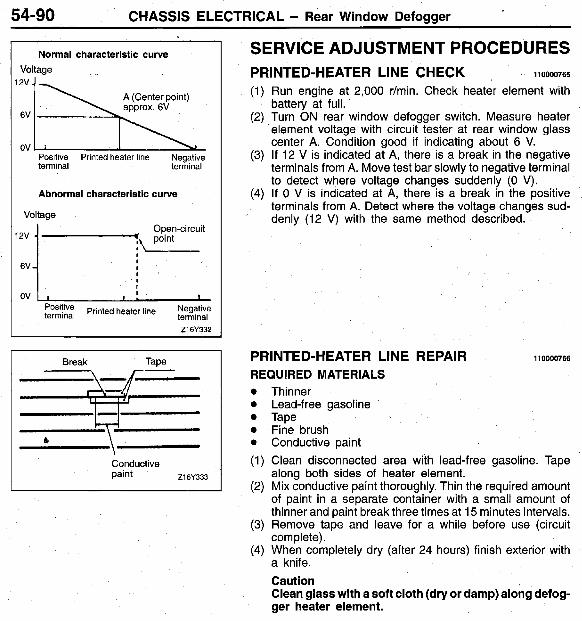
54-90 CHASSIS ELECTRICAL - Rear Window Defogger
Normal characteristic curve Voltage 2v
6V
ov Positive Printed heater line Negative terminal terminal
Abnormal characteristic curve
Voltage Open-circuit
y, point
ov 1 I I I , I
Printed heater line Negative terminal Z16Y332
Break Tape
\ 64
Conductive paint 216Y333
SERVICE ADJUSTMENT PROCEDURES
(1) Run engine at 2,000 r/min. Check heater element with battery at full.
(2) Turn ON rear window defogger switch. Measure heater element voltage with circuit tester at rear window glass center A. Condition good if indicating about 6 V.
(3) If 12 V is indicated at A, there is a break in the negative terminals from A. Move test bar slowly to negative terminal to detect where voltage changes suddenly (0 V).
(4) If 0 V is indicated at A, there is a break in the positive terminals from A. Detect where the voltage changes sud- denly (12 V) with the same method described.
PRINTED-HEATER LINE CHECK 110000765
PRINTED-HEATER LINE REPAIR 110000766
REQUIRED MATERIALS 0 Thinner 0 Lead-free gasoline 0 Tape 0 Fine brush 0 Conductive paint (1) Clean disconnected area with lead-free gasoline. Tape
along both sides of heater element. (2) Mix conductive paint thoroughly. Thin the required amount
of paint in a separate container with a small amount of thinner and paint break three times at 15 minutes intervals.
(3) Remove tape and leave for a while before use (circuit complete).
(4) When completely dry (after 24 hours) finish exterior with a knife. Caution Clean glass with a soft cloth (dry or damp) along defog- ger heater element.

CHASSIS ELECTRICAL - Rear Window Defogger 54-91
REAR WINDOW DEFOGGER REMOVAL AND INSTALLATION
<Rear Window Defogger Switch> - 110003662
1
Removal steps 1. Knee protector 2. Air outlet center panel assembly
(Refer to P.54-38.)
A1650732
3. Switch holder 4. Switch plug 5. Defogger switch

54-92 CHASSIS ELECTRICAL - Rear Window Defogger
INSPECTION Defogger switch
I
Indicator ,
light
OFF
ON
L
I
Illumination light
Switch Terminal No.
4 1 6 1 1 1 3
Power is not supplied
1 2-5 terminals
1 1-3 terminals
No continuity
Continuity
Defogger relay (1) Remove the defogger relay from the passenger compart-
ment relay box.
(2) Apply voltage to terminal 3, and check the continuity be- tween the terminals when terminal 1 is grounded.
1 Power is supplied 1 2-5 terminals 1 Continuitv I
I 0000’568 I