minivol portable air sampler operation...
TRANSCRIPT

MiniVolPortable Air Sampler
Operation Manual
Airmetrics2121 Franklin Boulevard, #9
Eugene, OR 97403U.S.A.
PHONE: 541. 683.5420FAX: 541. 683.1047
E-mail: [email protected] www.airmetrics.com
Notice:
Information in this manual is subject to change without notice and does not representa commitment on the part of Airmetrics, which reserves the right to make changes inconstruction, design, specifications, and/or procedures that may not be reflected inthis manual.
Printing History
Manual Version 1.0 - October, 1992, applies to Sampler Models 3.xManual Version 1.0a - November, 1992, applies to Sampler Models 3.xManual Version 1.1 - June, 1993, applies to Sampler Model 4.0Manual Version 1.1a - January, 1994, applies to Sampler Model 4.0Manual Version 1.2 - December, 1994, applies to Sampler Model 4.0Manual Version 1.2a - July, 1996, applies to Sampler Model 4.1Manual Version 4.2 - May, 1997 applies to Sampler Model 4.2Manual Version 4.2a - February, 1998 applies to Sampler Model 4.2Manual Version 4.2b - December, 2000 applies to Sampler Model 4.2Manual Version 4.2c - June, 2001 applies to Sampler Model 4.2
Table of Contents
Airmetrics i
Table of Contents
1 INTRODUCTION 1Principles of Operation . . . . . . . . . . . . . . . . . . . . . . . . . . . . . . . . . . . . . . . . . . . 1
Particulate Matter Sampling Mode . . . . . . . . . . . . . . . . . . . . . . . . . . . . . . 2Integrated Gas Sampling Mode . . . . . . . . . . . . . . . . . . . . . . . . . . . . . . . . . 3
2 GETTING STARTED 5Inspecting Components . . . . . . . . . . . . . . . . . . . . . . . . . . . . . . . . . . . . . . . . . . . 5Charging Batteries . . . . . . . . . . . . . . . . . . . . . . . . . . . . . . . . . . . . . . . . . . . . . . . 5Connecting Sampler Body and Battery Pack . . . . . . . . . . . . . . . . . . . . . . . . . . 6Removing Pump and Timer Assembly . . . . . . . . . . . . . . . . . . . . . . . . . . . . . . . 7Turning the Sampler On/Off . . . . . . . . . . . . . . . . . . . . . . . . . . . . . . . . . . . . . . . 8Programming the Timer . . . . . . . . . . . . . . . . . . . . . . . . . . . . . . . . . . . . . . . . . . 8
Setting the Real-Time Clock . . . . . . . . . . . . . . . . . . . . . . . . . . . . . . . . . . . 9Setting the On/Off Times . . . . . . . . . . . . . . . . . . . . . . . . . . . . . . . . . . . . . . 9Setting the Timer to “On,” “Auto,” and "Off" Modes . . . . . . . . . . . . . . . 10
Checking for Leaks . . . . . . . . . . . . . . . . . . . . . . . . . . . . . . . . . . . . . . . . . . . . . 11
3 CONTROLS AND ADJUSTMENTS 13All Operating Modes . . . . . . . . . . . . . . . . . . . . . . . . . . . . . . . . . . . . . . . . . . . . 13
Elapsed Time Totalizer . . . . . . . . . . . . . . . . . . . . . . . . . . . . . . . . . . . . . . 13Programmable Timer . . . . . . . . . . . . . . . . . . . . . . . . . . . . . . . . . . . . . . . . 13Flowmeter . . . . . . . . . . . . . . . . . . . . . . . . . . . . . . . . . . . . . . . . . . . . . . . . 13Flow Rate Adjustment . . . . . . . . . . . . . . . . . . . . . . . . . . . . . . . . . . . . . . . 1312V Battery Power Connector . . . . . . . . . . . . . . . . . . . . . . . . . . . . . . . . . 14Low Flow Threshold Indicator . . . . . . . . . . . . . . . . . . . . . . . . . . . . . . . . 14Low Flow Cutoff Indicator . . . . . . . . . . . . . . . . . . . . . . . . . . . . . . . . . . . 15Low Flow Zero & Cutoff Adjustments . . . . . . . . . . . . . . . . . . . . . . . . . . 15Low Battery Indicator . . . . . . . . . . . . . . . . . . . . . . . . . . . . . . . . . . . . . . . 16Lo-Flow/Lo-Battery Reset Switch . . . . . . . . . . . . . . . . . . . . . . . . . . . . . . 16ON/AUTO/OFF Button . . . . . . . . . . . . . . . . . . . . . . . . . . . . . . . . . . . . . . 17
Integrated Gas Sampling Option . . . . . . . . . . . . . . . . . . . . . . . . . . . . . . . . . . . 17Solenoid Valve Output Connectors . . . . . . . . . . . . . . . . . . . . . . . . . . . . . 18Active Solenoid Output Indicators . . . . . . . . . . . . . . . . . . . . . . . . . . . . . . 18Manual Sequence Advance Button . . . . . . . . . . . . . . . . . . . . . . . . . . . . . 18
Airmetrics MiniVol Users Guide
ii Airmetrics
Pulse Interval Adjustment . . . . . . . . . . . . . . . . . . . . . . . . . . . . . . . . . . . . 18Pulse Duration Adjustment . . . . . . . . . . . . . . . . . . . . . . . . . . . . . . . . . . . 18Power On/Off . . . . . . . . . . . . . . . . . . . . . . . . . . . . . . . . . . . . . . . . . . . . . . 19Pulse Indicator . . . . . . . . . . . . . . . . . . . . . . . . . . . . . . . . . . . . . . . . . . . . . 19Overlap Jumper . . . . . . . . . . . . . . . . . . . . . . . . . . . . . . . . . . . . . . . . . . . . 19
4 PARTICULATE MATTER SAMPLING 21Consumables . . . . . . . . . . . . . . . . . . . . . . . . . . . . . . . . . . . . . . . . . . . . . . . . . . 21Siting Requirements . . . . . . . . . . . . . . . . . . . . . . . . . . . . . . . . . . . . . . . . . . . . 21Attaching the Mounting Cradle . . . . . . . . . . . . . . . . . . . . . . . . . . . . . . . . . . . . 21Preparing the Sampler . . . . . . . . . . . . . . . . . . . . . . . . . . . . . . . . . . . . . . . . . . . 22
Flow Rate . . . . . . . . . . . . . . . . . . . . . . . . . . . . . . . . . . . . . . . . . . . . . . . . . 24Flowmeter Calibration . . . . . . . . . . . . . . . . . . . . . . . . . . . . . . . . . . . . . . . 25
Preseparator/Filter Holder Assembly . . . . . . . . . . . . . . . . . . . . . . . . . . . . . . . 25Clean and Grease Impactor . . . . . . . . . . . . . . . . . . . . . . . . . . . . . . . . . . . 25Installing Filters . . . . . . . . . . . . . . . . . . . . . . . . . . . . . . . . . . . . . . . . . . . . 26
Preparing the Battery Pack . . . . . . . . . . . . . . . . . . . . . . . . . . . . . . . . . . . . . . . 27Battery Charging . . . . . . . . . . . . . . . . . . . . . . . . . . . . . . . . . . . . . . . . . . . 27Changing/Installing Battery Pack on Sampler . . . . . . . . . . . . . . . . . . . . . 28Other Battery Checks . . . . . . . . . . . . . . . . . . . . . . . . . . . . . . . . . . . . . . . . 28
Setting the Desired Sampling Time . . . . . . . . . . . . . . . . . . . . . . . . . . . . . . . . 29Particulate Matter Sampling Procedure . . . . . . . . . . . . . . . . . . . . . . . . . . . . . 29Particulate Matter Sample Retrieval . . . . . . . . . . . . . . . . . . . . . . . . . . . . . . . . 30
Exposed Filter . . . . . . . . . . . . . . . . . . . . . . . . . . . . . . . . . . . . . . . . . . . . . 32Error Conditions . . . . . . . . . . . . . . . . . . . . . . . . . . . . . . . . . . . . . . . . . . . 33
Low Battery Indicator ON . . . . . . . . . . . . . . . . . . . . . . . . . . . . . . . . 33Low Flow Indicator ON . . . . . . . . . . . . . . . . . . . . . . . . . . . . . . . . . . 33Overriding Low Flow/Low Battery Indicators . . . . . . . . . . . . . . . . . 34
5 INTEGRATED GAS SAMPLING 35Consumables . . . . . . . . . . . . . . . . . . . . . . . . . . . . . . . . . . . . . . . . . . . . . . . . . . 35Siting Requirements . . . . . . . . . . . . . . . . . . . . . . . . . . . . . . . . . . . . . . . . . . . . 35Attaching the Mounting Cradle . . . . . . . . . . . . . . . . . . . . . . . . . . . . . . . . . . . . 35Preparing the Sampler . . . . . . . . . . . . . . . . . . . . . . . . . . . . . . . . . . . . . . . . . . . 36
Operation Modes - Standard Mode or Overlap Mode . . . . . . . . . . . . . . . 36Adjusting Pulse Frequency and Duration . . . . . . . . . . . . . . . . . . . . . . . . 39
Pulse Interval Adjustment . . . . . . . . . . . . . . . . . . . . . . . . . . . . . . . . . 40Pulse Duration Adjustment . . . . . . . . . . . . . . . . . . . . . . . . . . . . . . . . 40
Preparing the Sampler . . . . . . . . . . . . . . . . . . . . . . . . . . . . . . . . . . . . . . . . . . . 41

Table of Contents
Airmetrics iii
Installing Tedlar® Bags and Attaching Canisters . . . . . . . . . . . . . . . . . . 42Integrated Gas Sampling Procedure . . . . . . . . . . . . . . . . . . . . . . . . . . . . . . . . 44Gas Sample Retrieval . . . . . . . . . . . . . . . . . . . . . . . . . . . . . . . . . . . . . . . . . . . 45
6 HARDWARE DESCRIPTION 47Pneumatic System . . . . . . . . . . . . . . . . . . . . . . . . . . . . . . . . . . . . . . . . . . . . . . 47
Pneumatic System Flow Schematic . . . . . . . . . . . . . . . . . . . . . . . . . . . . . 47Filter Holder Assembly . . . . . . . . . . . . . . . . . . . . . . . . . . . . . . . . . . . . . . 47Flowmeter . . . . . . . . . . . . . . . . . . . . . . . . . . . . . . . . . . . . . . . . . . . . . . . . 47Flow Control System . . . . . . . . . . . . . . . . . . . . . . . . . . . . . . . . . . . . . . . . 47Miniature Brushless D.C. Double Acting Diaphragm Pump . . . . . . . . . . 47
Electronics System . . . . . . . . . . . . . . . . . . . . . . . . . . . . . . . . . . . . . . . . . . . . . 49Motherboard . . . . . . . . . . . . . . . . . . . . . . . . . . . . . . . . . . . . . . . . . . . . . . 49Power . . . . . . . . . . . . . . . . . . . . . . . . . . . . . . . . . . . . . . . . . . . . . . . . . . . . 49Programmable Timer . . . . . . . . . . . . . . . . . . . . . . . . . . . . . . . . . . . . . . . . 49Flow Controller Circuit . . . . . . . . . . . . . . . . . . . . . . . . . . . . . . . . . . . . . . 50Elapsed Time Totalizer . . . . . . . . . . . . . . . . . . . . . . . . . . . . . . . . . . . . . . 50Interconnect Board . . . . . . . . . . . . . . . . . . . . . . . . . . . . . . . . . . . . . . . . . . 50Motherboard Electronics Schematic . . . . . . . . . . . . . . . . . . . . . . . . . . . . 50Battery Pack Charger Electronics Schematic . . . . . . . . . . . . . . . . . . . . . . 50Valve Driver Board Electronics Schematic . . . . . . . . . . . . . . . . . . . . . . . 50
7 MAINTENANCE 51Preseparator/Filter Holder Assembly . . . . . . . . . . . . . . . . . . . . . . . . . . . . . . . 51
Impactor Cleaning . . . . . . . . . . . . . . . . . . . . . . . . . . . . . . . . . . . . . . . . . . 51Flow Control System . . . . . . . . . . . . . . . . . . . . . . . . . . . . . . . . . . . . . . . . . . . 52Programmable Timer . . . . . . . . . . . . . . . . . . . . . . . . . . . . . . . . . . . . . . . . . . . 53Battery Pack . . . . . . . . . . . . . . . . . . . . . . . . . . . . . . . . . . . . . . . . . . . . . . . . . . 53Cleaning/Inspecting Pump Valves and Diaphragms . . . . . . . . . . . . . . . . . . . . 53
Cleaning/Inspecting Pump Head Valves . . . . . . . . . . . . . . . . . . . . . . . . . 54
8 TROUBLESHOOTING 55
Airmetrics MiniVol Users Guide
iv Airmetrics
Appendices
A SAMPLER FLOW RATE CALIBRATION 59B GRAVIMETRIC ANALYSIS PROCEDURE 67C QUICK REFERENCE 79D WARRANTY POLICY 83E REPLACING DAMAGED/DEFECTIVE COMPONENTS 85F PARTS LIST 87G FORMS and SCHEMATICS 105
List of Figures
Figure 2.1. Attaching Battery Pack 7Figure 2.2. Programmable Timer 8Figure 3.1. Sampler Controls and Adjustments 14Figure 4.1. Mounted Sampler 23Figure 4.2. Tubing Configuration for PM Sampling Mode 24Figure 4.3. PM10 Preseparator and Filter Holder Assembly 26Figure 4.4. PM2.5 Preseparator and Filter Holder Assembly 27Figure 5.1. Tubing Configuration for Integrated Gas Sampling Mode 36Figure 5.2. Installing Tedlar® Bag 42Figure 5.3. Attaching Bag Canisters and Tubing 43Figure 6.1. Pneumatic System Flow Schematic 48Figure 7.1. Regreasing PM2.5 Impactor 52Figure A.1. Portable Sampler Calibration Output 61Figure B.1. Relative Humidity Effects on Quartz Filters 72Figure F.1. Main Circuit Board Parts Identification. 88Figure F.2. Valve Driver Board Parts Identification 90Figure F.4. Preseparator and Filter Parts Identification 94Figure F.5. Battery Pack Parts Identification 97Figure F.6. Integrated Gas Sampling Bag Parts Identification 99Figure F.7. Mounting Hardware Parts Identification 101

Section 1: Introduction
Airmetrics 1
1 INTRODUCTION
The MiniVol Portable Air Sampler is an ambient air sampler for particulate matterand non-reactive gases. The patented low flow technology used in the MiniVol wasdeveloped jointly by the U. S. Environmental Protection Agency (EPA) and theLane Regional Air Pollution Authority in an effort to address the need for portableair pollution sampling technology.
While not a reference method sampler, the MiniVol gives results that closelyapproximate reference method air quality data. Both accurate and precise, the batteryoperated, lightweight MiniVol is ideal for sampling at remote sites or areas withoutpower. In addition, the low cost of the sampler allows a network of MiniVols to bedeployed at a fraction of the cost for a similar reference station network.
The MiniVol features a 7-day programmable timer, a constant flow control system,an elapsed time totalizer, rechargeable battery packs, and all-weather PVCconstruction. The MiniVol can be configured to sample for just particulate matter,just gases, or both simultaneously.
Principles of Operation
The MiniVol Portable Air Sampler is basically a pump controlled by aprogrammable timer which can be set to make up to six "runs" within 24 hours orthroughout a week. When used outdoors it may be hung from a bracket mounted ona variety of structures—utility poles, trees, fence posts, etc.
The sampler is equipped to operate from either AC or DC power sources. In the DCoperational mode, the sampler operates from a battery pack, thus making thesampling site independent of line power. In the AC mode the battery pack isconnected to line power and mated to the sampler unit. This configuration chargesthe battery while using AC power. The MiniVol comes with two battery packs toaccomplish continuous field sampling. A charged battery pack is capable ofoperating the sampler for up to 24 sampling hours on a single charge.
The sampler is equipped with two "fault circuits":
Airmetrics MiniVol Users Guide
2 Airmetrics
� A low battery circuit automatically shuts the sampler down should therechargeable lead-acid battery fail to supply sufficient voltage (below 10.3volts) to the pump. This feature protects the battery which could be damaged ifused continuously at low voltage. A "low-battery" indicator lights to alert theoperator of this condition.
� A low flow circuit monitors the flow rate. Should excessive accumulation ofparticulate matter or some restriction in the tubing cause the air flow to fallbelow a specified rate, the sampler shuts down and a "low flow" indicator lightsto alert the operator.
An Elapsed Time Totalizer linked in parallel with the pump records the total timein hours of pump operation.
PARTICULATE MATTER SAMPLING MODE
In the particulate matter (PM) sampling mode, air is drawn through a particle sizeseparator and then through a filter medium. Particle size separation is achieved byimpaction. Critical to the collection of the correct particle size is the correct flow ratethrough the impactor. For the MiniVol, the actual volumetric flow rate must be 5liters per minute (5 lpm) at ambient conditions. To assure a constant 5 lpm flow ratethrough the size separator at differing air temperatures and atmospheric pressures,the sampler must be adjusted for each sampling project.
NOTE: The terms SIZE SEPARATOR, PRESEPARATOR and IMPACTOR areused interchangeably in this manual.
Impactors are available with a 10 micron cut-point (PM10) and a 2.5 micron cut-point(PM2.5). Operating the sampler without an impactor allows for collection of totalsuspended particulate matter (TSP).
The inlet tube downstream from the filter takes the air to the twin cylinderdiaphragm pump. From the pump, air is forced through a standard flowmeter whereit is exhausted to the atmosphere inside the sampler body.
The programmable timer will automatically turn the pump off at the end of asampling period. The sampler must then be serviced and set up for the next samplingperiod. Servicing includes removing the sampler from its hanging bracket, removingthe filter holder with the exposed filter inside from the sampler, and attaching a new

Section 1: Introduction
Airmetrics 3
filter holder with a fresh filter. The battery pack is also changed at this time.
The sampling technique used by the MiniVol is a modification of the PM10 referencemethod described in the U. S. Code of Federal Regulations (40 CFR part 50,Appendix J). Under this criteria, a PM10 sampler must have: 1) a sample air inletsystem to provide particle size discrimination, 2) a flow control device capable ofmaintaining a flow rate within specified limits, 3) means to measure the flow rateduring the sampling period, and 4) a timing control device capable of starting andstopping the sampler.
The Airmetrics MiniVol Portable Air Sampler meets all of these specifications. It isequipped with: 1) an inlet impactor capable of separating particulate matter to �10µm, 2) a flow control device which will maintain a specified flow rate, 3) aflowmeter to measure the flow rate during the sampling period, 4) an elapsed timemeter, and 5) a programmable timer that starts and stops the sampler unattended.
The MiniVol's flow rate is generally less than the flow rates used by referencemethod devices. The lower rate results in a greater deviation in accuracy at lowconcentrations of particulate matter where precision can be lost through the handlingand weighing of a minute particulate sample. However, at high particulateconcentrations the sampler produces results that are precise and comparable toreference method samplers.
While the MiniVol's sampling method is not a reference or equivalent method, it hasproven to be an excellent indicator of absolute ambient PM10 concentrations.Although the method used by portable PM10 sampling does not wholly conform orcomply with the reference method, the data collected by the sampler still serve as auseful supplement to data generated by PM10 reference methods.
INTEGRATED GAS SAMPLING MODE
In the integrated gas sampling mode, the sampler can accommodate one or two bagmodules. The bags may be filled one at a time or simultaneously within aprogrammable period. There are two circuits which control the gas sampling:
1. A tuneable intervalometer, or pulse circuit, determines the rate at which a bag isfilled. The circuit sends an electronic pulse to open a solenoid on the valvedriver board. The duration of each pulse can be adjusted from approximately 50
Airmetrics MiniVol Users Guide
4 Airmetrics
to 750 milliseconds. The pulses can also be adjusted for frequency, from onepulse every 15 seconds to continuously on.
2. A bag sequencer determines which of the two bags is being filled during anyprogrammed interval.
While the bags that are supplied with the samplers are made of relatively non-reactive Tedlar® (polyvinyl fluoride), other parts of the air path are made of PVC,polyethylene, silicone rubber, and other substances that are more reactive.Consequently, you should not use the MiniVol to collect gas samples that are to beanalyzed for reactive gases like ozone or sulfur dioxide.
In the gas sampling mode, the air that is used to fill the bags is diverted from thenormal air path just before the air is vented into the sampler case—at the end of theair path. Because of this, you may simultaneously collect a PM sample (the filterholder is situated at the beginning of the air path) while collecting a gas sample.

Section 2: Getting Started
Airmetrics 5
2 GETTING STARTED
Inspecting Components
When purchased, a standard MiniVol comes packed in two plastic carrying cases,one containing two battery packs and a transformer, the other containing the samplerand two preseparator/filter holder assemblies. A mounting cradle is shipped outsideof the carrying boxes. Each sampler includes:
� 1 pump module� 2 preseparator/filter holder assemblies� 2 battery packs� 1 18-volt transformer� 2 plastic carrying cases� 1 mounting cradle
If you ordered the Integrated Gas Sampling option, you will also receive:
� 1 valve driver board (pre-installed on back of main circuit board)� 4 collection canisters, each with a 6-liter Tedlar® bag� 1 24-inch bale bar with removable end caps� 1 special bale handle
Every order also includes an Operation Manual and a packet of spare parts.
On receipt, visually inspect the contents of the cases to account for all components.Compare the equipment delivered with the enclosed packing slip. Notify Airmetricsof any missing or damaged equipment (see Appendix D).
Charging Batteries
1. Connect the charging plug of the transformer to the charging jack on the firstbattery pack.
2. Plug the transformer into a fused AC outlet.
Airmetrics MiniVol Users Guide
6 Airmetrics
NOTE: A Switching AC Adaptor is supplied with a new sampler. This universaltransformer/adaptor is rated for 100-240 VAC, 50-60 Hz, and features a 3-poleplug. The user may need to purchase a standard computer power cord with localplug configuration to connect the transformer to a wall socket for batteryrecharge.
3. The green LED on the top of the battery will light indicating that the battery isbeing charged. When this light goes out, the battery is charged but continues toreceive a “trickle” charge as long as it is plugged into the charging transformer.A fully discharged battery requires at least 18 hours to be completely recharged.
4. If the battery will be used frequently, leave it plugged into the chargingtransformer until its next use. Leaving the battery plugged in allows it to receivea trickle charge maintaining the battery in a fully charged state. DO NOT,however, store the battery for extended periods of time while plugged into thecharging transformer.
� The charging LED (green) should light briefly even if the battery is alreadyfully charged. If the charging LED on the battery fails to light, either the LED isfaulty or the charger is defective (see "Troubleshooting" section).
� The batteries supplied with the sampler are of the lead-acid type. Since thesebatteries may vent hydrogen gas while charging, they must be charged in a well-ventilated area so that the hydrogen gas does not build to an explosiveconcentration.
Connecting Sampler Body and Battery Pack
1. Remove the packing foam from the bottom of the sampler body.
2. Lift the sampler over the battery pack and carefully insert the banana pinsextending from the sampler bottom into the sockets on the top of the batterypack. The pins are unevenly spaced and can fit only one way—the pin closestto a latch on the sampler body inserts into the odd colored receptacle on thebattery pack (see Figure 2.1).
3. Clamp the two latches.

Section 2: Getting Started
Airmetrics 7
Figure 2.1. Attaching Battery Pack
Removing Pump and Timer Assembly
The bale assembly bar secures the 6" diameter top cap to the sampler body. Toremove the pump and timer assembly from inside the sampler body:
1. Lift the pump and timer assembly out holding the 6" diameter top cap, takingcare not to pull the connecting wire loose or jar the pump hose fittings.
2. Since the short connecting wire does not allow the assembly to be removed fromthe sampler body beyond a few inches, rest the assembly on the edge of thesampler casing by using the triangular mount stand. Leave the battery attachedto the sampler to stabilize the unit, and hold the assembly by the top cap. DoNOT grasp the circuit board.
Airmetrics MiniVol Users Guide
8 Airmetrics
Figure 2.2. Programmable Timer
�
Turning the Sampler On/Off
The ON/AUTO/OFF button on theProgrammable Timer allows theoperator to manually turn thesampler on or off (or to place it inthe "Auto" mode in which it iscontrolled by programmed on/offsequences). As the ON/AUTO/OFFbutton is pressed, a bar at the loweredge of the LCD display moveshorizontally over the words "On","Auto" and "Off" which are printedon the timer case (see Figure 2.2).
With the sampler attached to acharged battery pack, press theON/AUTO/OFF button until the baris above the "On" legend. The redpower indicator (to the right of the
ON/AUTO/OFF button) shouldlight and the pump motor shouldstart.
If the Timer display does not respond, check the single AA battery on the circuitboard. Removing the battery resets the timer and clears the display.
While the sampler is running, press the ON/AUTO/OFF button, until the bar isover the OFF legend. The power indicator light will go off and the pump will stop
running.
Programming the Timer
The Programmable Timer can be set to run up to six on/off cycles within a 24 hourperiod, as well as to run for separate time periods on separate days within a 7-dayperiod. To set the timer, first set the real-time clock to establish the correct timeframe in which the cycles are to run. Next, enter the on/off times at which theprogrammed cycles are to begin and end. Finally, set the timer to "Auto" mode.

Section 2: Getting Started
Airmetrics 9
�
Refer to Figure 2.2 when performing the following procedures.
SETTING THE REAL-TIME CLOCK
1. DAY SET: Hold down the CLOCK button and press the WEEK button until thecorrect day appears at the top of the display.
2. TIME SET (Hour): Hold down the CLOCK button and press the HOUR buttonuntil the display indicates the correct hour. You may have to cycle through thehours twice to obtain the proper AM or PM (on the left side of the display).Seconds will automatically reset to zero.
3. TIME SET (Minutes): Hold down the CLOCK button and press the MIN buttonuntil the display indicates the correct minutes. Seconds will automatically resetto zero.
SETTING THE ON/OFF TIMES
1. Press the PROG button once. �2121 will appear near the lower left corner of thedisplay indicating that the power-on time for the first cycle is ready to beprogrammed.
2. Press the HOUR and MIN buttons to enter the power-on time for the first cycle.
3. Press the WEEK button to select the desired day. The days appear along the topof the display. Continuously pressing the WEEK button will sequentiallydisplay "Mo Tu We Th Fr Sa Su", "Mo", "Tu", "We", "Th", "Fr", "Sa", "Su","Mo Tu We Th Fr", "Sa Su" and finally back to "Mo Tu We Th Fr Sa Su".When more than one day is displayed, these days will all have the same power-on time.
4. After you have entered the power-on time and date for the first cycle, press thePROG button. �2))2)) now appears on the display to indicate that the power-offtime for the first cycle is ready to be programmed. Repeat steps 2 and 3 to enterthe desired power-off time.
The power-off time does not have to occur on the same day as the on time. In thisway, sampling may start on one day and end on the next day.
Airmetrics MiniVol Users Guide
10 Airmetrics
�
5. Press the PROG button again. �2121 appears on the display to indicate that thesecond power-on time is ready to be programmed. Repeat steps 2 to 4 to enterthe remaining power-on/power-off times (up to 6 on/off times).
6. Press the PROG button to step through the times you entered to make sure theyare correct.
Press the RST/RCL button to disable (ReSeT) or reactivate (ReCalL) any timeentries. When you disable a particular power-on/off entry, four dashes willappear instead of the time. When you reactivate an entry, it will return to thevalues that were set before you performed a reset.
Be sure to clear all unwanted time entries prior to sampling in the AUTO mode.Both ON and OFF entries need to be disabled for the unwanted programs to beinactive.
7. Press the CLOCK button to return to the real-time clock display.
8. Press the ON/AUTO/OFF button until the bar is positioned above the "OFF"legend.
SETTING THE TIMER TO “ON,” “AUTO,” AND "OFF" MODES
The ON/AUTO/OFF button is used to manually turn the sampler on or off, or toplace it in the "Auto" mode. A bar on the lower edge of the LCD display moves from"Off" to "Auto" to "On" as the button is pressed. In the "Auto" mode the sampler iscontrolled by the programmed on/off sequences.
� To manually turn the sampler ON, press the ON/AUTO/OFF button until the baron the lower edge of the display is above the "ON" legend. The pump will startand the power indicator will light.
� To manually turn the sampler OFF, press the ON/AUTO/OFF button until thebar is above the "OFF" legend.
� To set the timer to "AUTO" mode in which the sampler will be automaticallycontrolled by programmed sequences, first turn the sampler OFF. Then press theON/AUTO/OFF button until the bar is above the "AUTO" legend.

Section 2: Getting Started
Airmetrics 11
Checking for Leaks
To check for leaks, remove the preseparator/filter holder assembly and cover the airinlet at the top of the sampler body with the palm of the hand while the pump isrunning. The ball in the flowmeter should drop immediately to zero and remain therewithout movement. If it does not, a leak exists somewhere in the hoses and fittingsbetween the inlet and the flowmeter. Leaks on the inlet side of the pump areespecially critical, since flow measurement will not accurately reflect the amount ofair passing through the filter. The sampler will be measuring air passing through thefilter, plus whatever air may be entering through the leak.
� Verify that all push-on hose fittings are secure.
� Check the screw fittings attached to the pump. These must be screwed insecurely. Unlike pipe threads these fittings "seat" into their connecting socket.Do NOT attempt to tighten these fittings with a wrench, since too much pressurecould break them. If any appear loose, tighten by hand to a "finger snugness."
� Check the push-on hose fitting beneath the 6" white cap just below the quickconnect.
Airmetrics MiniVol Users Guide
12 Airmetrics
This page was intentionally left blank.

Section 3: Controls and Adjustments
Airmetrics 13
3 CONTROLS AND ADJUSTMENTS
All Operating Modes
The following controls (see Figure 3.1) are used to set the operation of the MiniVolin both the particulate matter sampling mode and the gas sampling mode.
ELAPSED TIME TOTALIZER
The Elapsed Time Totalizer displays the total number of hours, with a resolution oftenths of hours, that the pump has run. The totalizer accumulates time only while thepump is running. It cannot be reset to zero. The total hours should be recorded at thebeginning and end of each sampling period.
PROGRAMMABLE TIMER
The Programmable Timer controls the on/auto/off operation of the sampler. Thetimer allows up to six sampling times to be preprogrammed over twenty-four hoursor throughout a week (see "Programming the Timer").
FLOWMETER
The Flowmeter indicates the flow rate of air through the system in liters/minute. Theflow rate is adjusted using the "Flow Rate Adjustment".
The flowmeter readings must be taken from the center of the ball.
FLOW RATE ADJUSTMENT
The Flow Rate Adjustment potentiometer (knob) varies the sampler's flow rate asindicated by the level of the ball (read from the center of the ball) in the flowmeter.Slowly turn the knob until the air flow reaches the desired level. The sampler's FlowControl Circuit will attempt to maintain this flow rate by varying the speed of thepump as particulate matter accumulates on the filter.
Airmetrics MiniVol Users Guide
14 Airmetrics
ELAPSED T IMETOTALIZER
P R O G R A M M A B L ETIMER
F L O W M E T E R
S A M P L I N G F L O W R A T EA D J U S T M E N T
1 2 V B A T T E R Y P O W E RC O N N E C T O R
L O W F L O W C U T - O F FINDICATOR
ON/AUTO/OFFB U T T O N
L O - F L O WLO-BATTERY
R E S E T S W I T C H
L O W B A T T E R YINDICATOR
L O W F L O WZ E R O
A D J U S T M E N T
L O W F L O W C U T - O F FA D J U S T M E N T
L O W F L O WT H R E S H O L DINDICATOR
T R I A N G U L A RM O U N T S T A N D
Figure 3.1. Sampler Controls and Adjustments
12V BATTERY POWER CONNECTOR
The 12V Battery Power Connector is a standard phone plug-in jack which conductspower from the battery to the sampler.
LOW FLOW THRESHOLD INDICATOR
The Low Flow Threshold Indicator light is activated when the flow sensordetermines that the air flow rate has dropped some increment below the flow rate
Section 3: Controls and Adjustments
Airmetrics 15
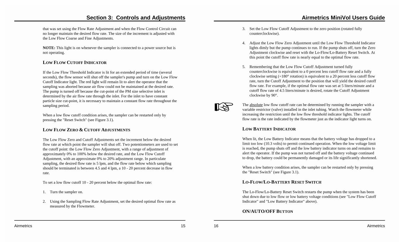
that was set using the Flow Rate Adjustment and when the Flow Control Circuit canno longer maintain the desired flow rate. The size of the increment is adjusted withthe Low Flow Coarse and Fine Adjustments.
NOTE: This light is on whenever the sampler is connected to a power source but isnot operating.
LOW FLOW CUTOFF INDICATOR
If the Low Flow Threshold Indicator is lit for an extended period of time (severalseconds), the flow sensor will shut off the sampler's pump and turn on the Low FlowCutoff Indicator light. The red light will remain lit to alert the operator that thesampling was aborted because air flow could not be maintained at the desired rate.The pump is turned off because the cut-point of the PM size selective inlet isdetermined by the air flow rate through the inlet. For the inlet to have constantparticle size cut-point, it is necessary to maintain a constant flow rate throughout thesampling period.
When a low flow cutoff condition arises, the sampler can be restarted only bypressing the "Reset Switch" (see Figure 3.1).
LOW FLOW ZERO & CUTOFF ADJUSTMENTS
The Low Flow Zero and Cutoff Adjustments set the increment below the desiredflow rate at which point the sampler will shut off. Two potentiometers are used to setthe cutoff point: the Low Flow Zero Adjustment, with a range of adjustment ofapproximately 0% to 100% below the desired rate, and the Low Flow CutoffAdjustment, with an approximate 0% to 20% adjustment range. In particulatesampling, the desired flow rate is 5 lpm, and the flow rate below which samplingshould be terminated is between 4.5 and 4 lpm, a 10 - 20 percent decrease in flowrate.
To set a low flow cutoff 10 - 20 percent below the optimal flow rate:
1. Turn the sampler on.
2. Using the Sampling Flow Rate Adjustment, set the desired optimal flow rate asmeasured by the Flowmeter.
Airmetrics MiniVol Users Guide
16 Airmetrics
�
3. Set the Low Flow Cutoff Adjustment to the zero position (rotated fullycounterclockwise).
4. Adjust the Low Flow Zero Adjustment until the Low Flow Threshold Indicatorlights dimly but the pump continues to run. If the pump shuts off, turn the ZeroAdjustment clockwise and reset with the Lo-Flow/Lo-Battery Reset Switch. Atthis point the cutoff flow rate is nearly equal to the optimal flow rate.
5. Remembering that the Low Flow Cutoff Adjustment turned fullycounterclockwise is equivalent to a 0 percent less cutoff flow rate and a fullyclockwise setting (�180° rotation) is equivalent to a 20 percent less cutoff flowrate, turn the Cutoff Adjustment to the position that will yield the desired cutoffflow rate. For example, if the optimal flow rate was set at 5 liters/minute and acutoff flow rate of 4.5 liters/minute is desired, rotate the Cutoff Adjustmentclockwise by 90°.
The absolute low flow cutoff rate can be determined by running the sampler with avariable restrictor (valve) installed in the inlet tubing. Watch the flowmeter whileincreasing the restriction until the low flow threshold indicator lights. The cutoffflow rate is the rate indicated by the flowmeter just as the indicator light turns on.
LOW BATTERY INDICATOR
When lit, the Low Battery Indicator means that the battery voltage has dropped to alimit too low (10.3 volts) to permit continued operation. When the low voltage limitis reached, the pump shuts off and the low battery indicator turns on and remains toalert the operator. If the pump was not turned off and the battery voltage continuedto drop, the battery could be permanently damaged or its life significantly shortened.
When a low battery condition arises, the sampler can be restarted only by pressingthe "Reset Switch" (see Figure 3.1).
LO-FLOW/LO-BATTERY RESET SWITCH
The Lo-Flow/Lo-Battery Reset Switch restarts the pump when the system has beenshut down due to low flow or low battery voltage conditions (see "Low Flow CutoffIndicator" and "Low Battery Indicator" above).
ON/AUTO/OFF BUTTON
Section 3: Controls and Adjustments
Airmetrics 17
The ON/AUTO/OFF Button manually turns the sampler on, off, or places it in the"Auto" mode. In the "Auto" position, the sampler is controlled by whateverprogrammed on/off sequences have been entered. A bar on the lower edge of theProgrammable Timer's LCD display moves from "On" to "Auto" to "Off" as thebutton is pressed (see "Programming the Timer" in Section 2).
Integrated Gas Sampling Option
Integrated bag filling is accomplished with a Valve Driver Circuit board that plugsinto the auxiliary connector on the back of the sampler motherboard. The ValveDriver Board controls the operation of the two solenoid valves that are mounted onthe board. This arrangement allows for collection of one or two bag samples during auser selected sampling period. For example, this option allows for collecting two 4-or 8-hour integrated bag samples.
Functionally, sample gas is supplied to the common inlet port of each normallyclosed solenoid valve by the constant back-pressure of the flow control system. Thesampler pump operates continuously at a pre-set flow rate to purge the system andsupply sample gas to the solenoids under pressure. The output port of each normallyclosed solenoid valve is connected to a bag module. Because the pump is operatingcontinuously during the sampling period, a PM sample may be collectedconcurrently with the integrated gas samples.
Electronically, the Valve Driver Board interacts with the Programmable Timer onthe motherboard to perform two functions: 1) control which solenoid valve isactivated, and 2) set the duration and frequency of the "on" time for the activesolenoid valve.
A 4-step circular sequencing circuit advances each time the programmable timer onthe motherboard is switched from the "Auto" to the "Off" mode. There are foursolenoid output connectors with corresponding indicators located in the upperlefthand corner of the board that the solenoid valves can be plugged onto. Theindicators show the output that is, or will be, active when the sampler is switched tothe "On" mode either manually or by programmed operation. When a solenoidoutput is active and the sampler is in the "On" mode, a solenoid valve plugged ontothe active output pins is opened and closed by a tunable intervalometer circuit. Bothfrequency and duration of solenoid valve operation are adjustable to allow the usermaximum flexibility in controlling the bag filling rate.
Airmetrics MiniVol Users Guide
18 Airmetrics
SOLENOID VALVE OUTPUT CONNECTORS
The Solenoid Valve Output Connectors connect the solenoid valves to thesequencing circuit.
ACTIVE SOLENOID OUTPUT INDICATORS
The Active Solenoid Output Indicator LED above each Solenoid Valve OutputConnector indicates when that set of pins is active. When active the TunableIntervalometer will open and close the solenoid valve plugged into thecorresponding connector.
MANUAL SEQUENCE ADVANCE BUTTON
The Manual Sequence Advance Button allows the operator to select which SolenoidValve Output Connector will be active when the pump is turned on. The ManualAdvance only functions when the pump is off. Each time the pump is turned off, thechannel advances automatically.
PULSE INTERVAL ADJUSTMENT
The Pulse Interval (off time) of the circuit is adjustable over a range of 0-15 secondsby a 16-position rotary switch. This switch is located just to the right of the solenoidvalve output connectors. Switch positions are marked clockwise 0-9, and continueA-F. The interval between pulses increases in 1-second increments as the switch isrotated in a clockwise direction. Position "0" enables continuously on. Position "1"corresponds to a minimum delay time of one pulse per second, and position "F"indicates the maximum delay of 15 seconds between pulses. The fine adjustmentpotentiometer next to this control is for calibrating the one-second interval (fullycounterclockwise - decrease, fully clockwise - increase).
PULSE DURATION ADJUSTMENT
The duration (on time) of each pulse is adjustable over a range of 50-750milliseconds (ms). This adjustment is made by summing the calibrated intervalvalues of the dual in-line package (DIP) switches 1-4 on the 5-position DIP switchlocated in the upper right corner of the auxiliary board. Each switch has an assigned"On Time" value, and the on time for each pulse is determined by the sum of thevalues of switches in the "off" position. The "On Time" values for each switch are as

Section 3: Controls and Adjustments
Airmetrics 19
follows:
SW-1 = 50 msSW-2 = 100 msSW-3 = 200 msSW-4 = 400 ms
For Example: If SW-1, and SW-4 are in the "off" position, the solenoid on time foreach pulse would be 450 milliseconds. (50 + 400 ms = 450 ms).
The DOWN position is "on" for these switches. The fine adjustment next to thiscontrol adds an extra 50 ms to the total pulse time (fully counterclockwise - adds 50ms, fully clockwise - adds no time).
POWER ON/OFF
Switch 5 on this DIP switch is the on/off power switch for the auxiliary board, andmust be set to the "on" position for any functions to be active. The UP position is"on" for this switch, the opposite of the other dip switches.
PULSE INDICATOR
The Pulse Indicator flashes when the system is pulsing.
OVERLAP JUMPER
With the Overlap Jumper installed, and solenoid valves plugged into output ports 2& 4, both valves are energized when the sequencing circuit advances to position #3(LEDs for positions #2,3,4 are all on at this time). This allows for programming asampling period when both bags are filling simultaneously.
Airmetrics MiniVol Users Guide
20 Airmetrics
This page was intentionally left blank.

Section 4: Particulate Matter Sampling
Airmetrics 21
4 PARTICULATE MATTER SAMPLING
Sampling procedures for TSP, PM10, and PM2.5 are identical except for theconfiguration of the preseparator/filter holder assembly.
Consumables
During particulate matter sampling, the following consumables are needed forproper operation of the MiniVol:
� Impactor grease - Glisseal® Ht, Apiezon® M Grease, etc.� Solvent to mix with grease - hexane, white gas, lantern gas, etc.� 47 mm filters - pure quartz, pure Teflon®, Teflon®-coated glass, etc.� Petri slides - for storage and transport of the filters.
A microbalance accurate to one microgram is needed to weigh the filters.
Airmetrics offers all of the above consumables (except the solvent), along with filterweighing services.
Siting Requirements
Siting recommendations in this manual conform to the U. S. EnvironmentalProtection Agency requirements as stated in the U. S. Code of Federal Regulations(40 CFR part 58, Appendix E). When operating the sampler in locations underanother jurisdiction, the operator should follow the appropriate guidelines.
The MiniVol should be positioned with the intake upward and should be located inan unobstructed area at least 30 cm from any obstacle to air flow. Accessibility to theunit under all weather conditions, along with safety and security of the monitoringpersonnel and equipment, should be prime considerations.
Attaching the Mounting Cradle
The MiniVol Mounting Cradle is designed to mount onto a standard 1 1/4 inchantenna mast or comparable metal tubing (not supplied with the sampler). The mast
Airmetrics MiniVol Users Guide
22 Airmetrics
should be strapped securely to some other suitable structure�utility pole, parkingmeter, fence post, etc. (See Figure 4.1). Available separately from Airmetrics is a Y-Bracket Assembly which attaches to poles and provides a mast for the mountingcradle. (Also shown in Figure 4.1).
Preparing the Sampler
If the sampler is equipped with a valve driver board for integrated gas sampling,make sure to turn off the power (SW-5) on the auxiliary board before samplingunless integrated gas samples will be collected simultaneously with the particulatematter samples (refer to Section 5, “Integrated Gas Sampling”, for proper samplerpreparation for gas sampling). Be sure that the tubing conforms to the arrangementshown in Figure 4.2 (if a valve driver board is not attached) or Figure 5.1 (if a valvedriver board is attached).
TSP - Remove the impactor from the preseparator/filter holder assembly priorto sampling. Since the impactor will not be used, greasing and cleaning of theimpactor’s target disk need not be done.
PM10 - Use a PM10 impactor in the preseparator/filter holder assembly (seeFigure 4.3). Greasing and cleaning of the impactor’s target disk should beperformed initially and after every seventh sample (or more often if heavyloading is observed). Refer to Section 7, Maintenance, “Impactor Cleaning.”
PM2.5 - Use a PM2.5 impactor in the preseparator/filter holder assembly and aPM10 impactor in a multiple impactor adapter mounted on the preseparatorassembly tube but below the rain hat (see Figure 4.4). Greasing and cleaning ofthe impactors’ target disks should be performed initially and after every seventhsample (or more often if heavy loading is observed). Refer to Section 7,Maintenance, “Impactor Cleaning.”
To remove impactors, use your thumb to simply push the impactor out of its tubefrom bottom to top. When correctly installed, the impactor’s top is flush with thesurrounding preseparator tube or multiple impactor adapter tube.

Section 4: Particulate Matter Sampling
Airmetrics 23
Figure 4.1. Mounted Sampler
Airmetrics MiniVol Users Guide
24 Airmetrics
Figure 4.2. Tubing Configuration for PM Sampling Mode
Before transporting the MiniVol to the field, perform a laboratory check todetermine if it is operational. Turn the sampler on and observe the motorperformance. Check all tubing for crimps, cracks or breaks. Conduct a flow checkwith a "dummy" filter in place to simulate the load against the sampler pump.Investigate and correct any malfunctions before proceeding. Perform a single-pointflow rate check using a soap-bubble meter or other flow measuring device of knownaccuracy and compare to the curve established during calibration. The flow shouldbe within ±15% of 5 lpm at current conditions. If the unit fails to operate in thisrange, check the sampler for obvious crimps, battery malfunction, etc. The samplermust be repaired or recalibrated if the flow criteria are not met.
FLOW RATE
The particle size cut point of the preseparator is a function of the velocity with whichthe air stream passing through the preseparator hits the target. The preseparator isdesigned to have the correct cut point at an air flow rate of 5 lpm at ambient

Section 4: Particulate Matter Sampling
Airmetrics 25
conditions. Since the density of air and the behavior of the flowmeter are functionsof the ambient air temperature and atmospheric pressure, a flow rate set point mustbe calculated for each different sampling project.
The sampler air flow calibration curves that are supplied with each sampler containsthe necessary information needed to determine the flowmeter set point for aparticular ambient condition. Appendix A contains the complete instructions incalculating the flow set points.
FLOWMETER CALIBRATION
The sampler should be recalibrated if the flowmeter or the pulse dampener isreplaced.
Preseparator/Filter Holder Assembly
Depending on the required particle size separation, the configuration of thePreseparator changes. The attached Filter Holder Assembly contains a filter cassettein which the 47mm filter is supported by a filter support screen (see Figure 4.3 forPM10 and Figure 4.4 for PM2.5).
CLEAN AND GREASE IMPACTOR
Initially, and after every seventh sample, the impactor target should be cleaned andgreased under a laboratory fume hood (preferably) or any well ventilated area(including on-site). The cleaning frequency should be increased or decreaseddepending on the ambient loadings and degree of soiling observed on the target disk.
For Impactor cleaning procedures, see Section 7, Maintenance, "Impactor Cleaning."
Airmetrics MiniVol Users Guide
26 Airmetrics
Figure 4.3. PM10 Preseparator andFilter Holder Assembly
INSTALLING FILTERS
This procedure should take place in alaboratory or other clean area.Contact with and handling of allfilters should be limited to the edgesof the filters. Also, the use of non-serrated, Teflon®-tipped forceps isstrongly recommended. Filtersshould be kept in protective petrislides. Filters must never be bent orfolded.
1. Select a filter and remove coverfrom petri slide.
2. Using forceps, install the newfilter into the filter cassette.
3. Place the filter cassette in thefilter holder.
4. Replace preseparator adapterand screw down snugly.
5. Place an identifying tag on thefilter holder so that the IDnumber of the filter mounted inthe holder is known.
6. Place a clean, plastic bag over the top of the preseparator adapter inlet and pushthe rain cap snugly into place over the bag.

Section 4: Particulate Matter Sampling
Airmetrics 27
Figure 4.4. PM2.5 Preseparator and Filter Holder Assembly
7. Place the entire clean filter assembly into a second plastic bag, or other case, fortransporting to the site. It is best to keep the filter assembly in a vertical positionuntil installed on the sampler.
Preparing the Battery Pack
BATTERY CHARGING
After each sampling run, the used battery pack should be charged for a minimum of18 hours or overnight. The battery need not be completely discharged beforerecharging.
Airmetrics MiniVol Users Guide
28 Airmetrics
The rechargeable battery features a green charging light and comes with a universaltransformer that connects to wall sockets by a standard computer-type power cord.Previous to December, 1997, the batteries featured a red charging light and weresupplied with an 18-VAC Tamura Transformer.
If you own both types of batteries and transformers, please note the following:
� The 18-VAC Tamura Transformer CANNOT charge the new green LED-equipped batteries. The Tamura Transformer will burn out.
� The new Universal Transformer can charge both types of batteries. The oldbatteries, however, will take slightly longer to charge on the UniversalTransformer (18 hours vs. about 14 hours).
DO NOT store the battery while attached to the sampler as this will causeirreparable damage to the battery. The indicator lights that remain on when thebattery is connected to the sampler will discharge the battery past its 10.3 voltsafety cut-off point.
See “Charging Batteries” in the Getting Started section for instructions in the properprocedure to follow in recharging the batteries.
CHANGING/INSTALLING BATTERY PACK ON SAMPLER
1. Place the charged battery pack beside the sampler.
2. Unclasp the two side latches at the base of the sampler.
3. Lift the sampler off the used battery pack and place the sampler on the chargedbattery pack.
Note: The pin on the sampler closest to a side clip inserts into the odd coloredreceptacle on the battery pack (see Figure 2.1).
4. Reclamp the two side latches.
OTHER BATTERY CHECKS

Section 4: Particulate Matter Sampling
Airmetrics 29
A single AA battery on the circuit board operates the Programmable Timer. Thelifetime for this battery is approximately six months when it is left in place on thecircuit board. Be sure to observe the correct polarity when inserting a new AAbattery into the battery compartment.
Refer to Section 8, “Troubleshooting” for additional comments on battery functions.
Setting the Desired Sampling Time
Determine the time of the day when the sampler is to turn on and off. Program thetimer to turn the sampler on and off at these times (see "Programming the Timer" inSection 2).
Particulate Matter Sampling Procedure
After the sampler has been assembled, adjusted, verified to be in proper workingorder, and a filter loaded in the Filter Assembly, the sampler is ready to collect airsamples. Note: For a quick reference to the following steps, see "Particulate MatterSampling Routine at Site" (Appendix C). If a gas sample is also to be collectedsimultaneously, refer to Section 5, “Integrated Gas Sampling” for proper gassampling procedures.
1. Carefully transport the sampler to the field site. Verify that the sampler, whenfinally installed in the mounting cradle, will be positioned with the intakeupward in an unobstructed area at least 30 cm from any obstacle to air flow.
2. Place the sampler on a firm level surface.
3. Remove the clean Preseparator/Filter Holder Assembly from the plastictransport bag and remove the protective plastic bag under the rain cap. Attachthe assembly to the sampler top at the quick connect.
4. Record the following information on the PM Field Data Sheet: number of thefilter, the battery ID, sampler ID, ambient temperature and pressure, flowmeterreading, and elapsed time meter reading. (see Figure G.1 insert at the end of thisManual).
5. Unscrew either cap of the bale assembly bar and remove the bale assembly.
Airmetrics MiniVol Users Guide
30 Airmetrics
6. Lift the pump and timer assembly out by the 6" diameter top cap and rest it onthe edge of the sampler casing, using the triangular mount stand. Take care notto pull the connecting wire loose or jar the pump hose fittings. Hold the top capand do NOT grasp the center of the circuit board.
7. To obtain the beginning flow rate, press the ON/AUTO/OFF button to start thepump. On the LCD display, the horizontal bar should move to "ON".
8. If the flowmeter, which should be in the vertical position, indicates zero or avery low reading, check for restrictions in the tubing, or improperly seatedscrew fittings between the pump and the flowmeter.
9. Using the Flow Rate Adjustment control (see Figure 3.1), set the flowmeter flowwithin specifications for the project temperature and pressure conditions. Takethe reading of the flowmeter from the center of the ball. (See Appendix A).
10. Press the ON/AUTO/OFF button twice to stop pump.
11. Press the ON/AUTO/OFF button to set the timer to "Auto" mode. The SamplerMUST be in “Auto” mode before the operator leaves.
12. Place the pump and timer assembly back into the sampler body. Replace thebale assembly bar.
13. Using the hoisting pole, hook the bale assembly bar and raise the sampler, asvertically as possible, to the mounting cradle. This position not only more easilyaccommodates the sampler's weight, but prevents the hook from hitting andpossibly dislodging or breaking the preseparator/filter holder assembly. (SeeFigure 4.1).
Particulate Matter Sample Retrieval
As soon as possible after the end of the sampling period, the operator should returnto the monitoring site to retrieve the exposed filter. Potential for filter damage orchanges in sample mass due to particle loss, passive deposition, or volatilizationincreases if the filter is left in the sampler for extended periods. On the Field DataSheet record the ambient temperature (Ta), barometric pressure (Pa), and flowmeterreading.

Section 4: Particulate Matter Sampling
Airmetrics 31
Note: Ta and Pa readings may be estimated on site or may be obtained from a nearbyUS National Weather Service Forecast Office or airport weather station. Barometricpressure readings obtained from airports must be at station pressure (not corrected tosea level), and they may have to be corrected for differences between the elevationof the monitoring site and that of the airport. If Ta and Pa readings are not available,seasonal average temperature (Tavg) and barometric pressure (Pavg) may besubstituted. Care must be taken that the actual conditions at the site can bereasonably represented by such averages. It is therefore recommended that seasonalvalues represent actual values within 20 °C and 40 mm Hg.
Note: If a gas sample is also being retrieved, refer to Section 5 “Integrated GasSampling” for proper gas sample retrieval.
1. Remove the sampler from the mounting cradle using the hoisting pole. Positionyourself directly under the sampler, hook the bale assembly bar, and lower thesampler as vertically as possible. This vertical take-away not onlyaccommodates the sampler's weight, but prevents the hook from dislodging therain cap or damaging the preseparator/filter holder assembly (see Figure 4.1).
2. Place the sampler on a firm level surface.
3. Unscrew either cap of the bale assembly bar and remove the bar. Newersamplers come with quick-release snap buttons, so the bar need not be removed.
4. Lift the pump and timer assembly out by the top cap and rest it on the edge ofsampler body using the triangular mount stand. Take care not to pull theconnecting wire loose and hold the top cap.
5. Check the sampler face plate for any error conditions. If an error conditionsexists, refer to the “Error Conditions” section at the end of this chapter.
6. Verify correct time and day of week on time LCD.
7. Record elapsed time as shown on the Elapsed Time Totalizer.
8. Obtain ending flow rate:
� Press the ON/AUTO/OFF button twice to start the pump.
Airmetrics MiniVol Users Guide
32 Airmetrics
� With the flowmeter in a vertical position, record flow rate to the nearest10th of liter/minute (read at center of ball).
Note: If flowmeter indicates zero or very low reading, check the quick-disconnect to be sure the filter assembly is completely connected.
� Press the ON/AUTO/OFF button twice to stop the pump.
9. Place the pump and timer assembly into the sampler body. Do not replace thebale assembly bar.
10. Exchange a new preseparator/filter holder assembly for the exposed filter holderassembly. If possible, perform the exchange inside a building or vehicle tominimize exposure to the elements. Perform a cross-check of the exposed filternumber with the filter number recorded on the Field Data Sheet for the run justcompleted. Also, check the filter number against the site number.
11. Change Battery Pack (see page 28)
12. Obtain beginning flow rate (see "Particulate Matter Sampling Procedure" above,steps 7 to 12).
13. Make sure the timer is set for the desired period and in the “AUTO” mode.
14. Place the pump and timer assembly back into sampler body. Replace the baleassembly bar.
15. Using the hoisting pole, hook the bale bar and raise the sampler, as vertically aspossible, to the mounting cradle.
EXPOSED FILTER
1. In the laboratory, unscrew the filter holder and remove the filter cassette.
2. Locate the petri slide with the filter number which matches the number on theside of the filter holder assembly. This is the original petri slide in which thefilter came.
3. Use the cassette separator (P/N 600-007) to remove the top half of the filter
Section 4: Particulate Matter Sampling
Airmetrics 33
cassette.
4. Using tweezers, carefully remove the exposed filter from the filter cassette andplace it into its original petri slide, replacing the petri slide lid when finished.(Be sure to replace the filter support screen in the filter cassette assembly).
5. Remove the old ID tag from the filter holder assembly base and discard.(Recheck this number to be sure it matches the number on the petri slide.)
ERROR CONDITIONS
Low Battery Indicator ON
Should the Low Battery Indicator be ON at the end of a sampling period, check theElapsed Time Totalizer to determine the length of time the sampler ran beforeshutting off. If the time is short (e.g., only 2 hours out of a programmed 8 or 10hours), perhaps the battery was not completely charged or is failing to hold a charge.Note the battery number and, after recharging in the lab, observe performance in thenext sampling period. If the battery fails again, it is most likely defective and shouldbe replaced.
If a different battery performs in the same manner after shown to be fully charged,the pump motor is perhaps drawing more current than it should. If possible, install apump from another sampler. If this solves the problem, the previous pump motor islikely defective and should be replaced. If the problem continues, a more seriousfault is occurring which should be referred to Airmetrics (see Appendix D).
Low Flow Indicator ON
Should the Low Flow Indicator be found ON at the end of sampling period, firstcheck the Elapsed Time Totalizer to determine the length of time the sampler ranbefore shutting off. The possible causes for low flow are:
� Low Battery: Although power did not fall to the 10.3V lower limit that wouldshut down the system, the pump may not have been receiving enough voltage tomaintain the desired air flow.
� Air Restriction: If the battery is sound, the problem may be due to a restrictionin the air inlet, filter holder, or tubing. Check for crimps or other possible
Airmetrics MiniVol Users Guide
34 Airmetrics
restrictions. Also, a broken or loose tubing fitting on the outlet side of the pumpcould cause a low flow condition. It is also possible for excessive moisture onthe filter (rain, condensation) to cause enough flow resistance for the Low FlowIndicator to come on.
� Pump Malfunction: The low flow condition could be the result of decreasedpump efficiency, which is usually caused by damaged or contaminated pumphead components (valves, diaphragms). Check to see if the pump can maintain afree (unrestricted) airflow rate of at least 5 lpm. If not, see Section 7 for pumpmaintenance instructions.
� NOTE: The Low Flow Threshold Indicator normally lights whenever thesampler is attached to a power source but is not operating.
Overriding Low Flow/Low Battery Indicators
When Low Flow and Low Battery Indicator lights are on, the system can be restartedby pressing the Reset Switch. The system will usually run enough to perform a brieffield inspection and to obtain final flow rates. Pressing and holding the switchprovides continuous override of the fault circuit.
Section 5: Integrated Gas Sampling
Airmetrics 35
5 INTEGRATED GAS SAMPLING
MiniVol sampling procedures for all non-reactive gases are the same. It should alsobe noted that the MiniVol simply collects a gas sample. Analyzing a gas samplemust be done separately with the proper gas analyzing equipment.
Consumables
No consumables are needed except for the occasional replacement Tedlar® bagshould one become damaged. Contact Airmetrics for replacement bags.
Siting Requirements
Siting recommendations in this manual conform to the U. S. EnvironmentalProtection Agency requirements as stated in the U. S. Code of Federal Regulations(40 CFR part 58, Appendix E). When operating the sampler in locations underanother jurisdiction, the operator should follow the appropriate guidelines.
As with particulate matter sampling, the MiniVol should be positioned with theintake upward and located in an unobstructed area at least 30 cm from any obstacleto air flow. Accessibility to the unit under all weather conditions, along with safetyand security of the monitoring personnel and equipment, should be primeconsiderations.
Attaching the Mounting Cradle
Mount the MiniVol cradle onto a standard 1 1/4 inch antenna mast or comparablemetal tubing, which itself is strapped securely to another supporting structure�utilitypole, parking meter, fence post, etc. (see Figure 4.1).
Available separately from Airmetrics is a Y-Bracket Assembly for pole mountingwhich provides a mast for attachment of the mounting cradle.
Airmetrics MiniVol Users Guide
36 Airmetrics
Figure 5.1. Tubing Configuration for Integrated Gas SamplingMode
Preparing the Sampler
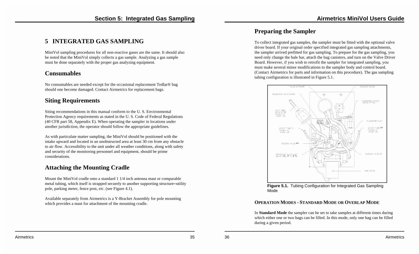
To collect integrated gas samples, the sampler must be fitted with the optional valvedriver board. If your original order specified integrated gas sampling attachments,the sampler arrived prefitted for gas sampling. To prepare for the gas sampling, youneed only change the bale bar, attach the bag canisters, and turn on the Valve DriverBoard. However, if you wish to retrofit the sampler for integrated sampling, youmust make several minor modifications to the sampler body and control board.(Contact Airmetrics for parts and information on this procedure). The gas samplingtubing configuration is illustrated in Figure 5.1.
OPERATION MODES - STANDARD MODE OR OVERLAP MODE
In Standard Mode the sampler can be set to take samples at different times duringwhich either one or two bags can be filled. In this mode, only one bag can be filledduring a given period.
Section 5: Integrated Gas Sampling
Airmetrics 37
To operate in Standard Mode:
� Plug the solenoids into desired positions 1-4.
� Remove Overlap Jumper.
� Advance to desired starting channel with Manual Advance Button.
Note: The Manual Advance only functions when the pump is off. Eachtime the pump is turned off, the channel advances automatically.
� Set timer as desired.
Active Solenoid Output Indicators in standard mode:
��� channel 1 on��� channel 2 on��� channel 3 on��� channel 4 on
Example 1: We wish to take two CO samples, one bag filling from 7:00 am to 3:00pm, and the second from 3:00 pm to 11:00 pm.
1) Plug bag 1 solenoid into Solenoid Output Connector 1; plug bag 2 solenoidinto Solenoid Output Connector 2.
2) Set the timer: set timer Program 1 to turn on at 7:00 am and off at 3:00 pm.Set timer Program 2 to turn on at 3:01 pm and off at 11:00 pm. The one minutedelay between the first program's off time and the second program's on time isnecessary to advance the sequencing valve to the next cycle.
Example 2: We wish to take two CO samples (from 7:00 am to 3:00 pm, and from3:00 pm to 11:00 pm) while also collecting a PM10 sample from 1:00 am to11:00 pm.
1) Plug bag 1 solenoid into Solenoid Output Connector 2; plug bag 2 solenoidinto Solenoid Output Connector 3.
2) Set the timer:
Airmetrics MiniVol Users Guide
38 Airmetrics
a) Set timer Program 1 to turn on at 1:00 am and off at 7:00 am. Duringthis program, neither bags will be filled but air will be drawn through the PM10
filter.
b) Set timer Program 2 to turn on at 7:01 am and off at 3:00 pm. Air willbe drawn through the filter and bag 1 will be filled.
c) Set timer Program 3 to turn on at 3:01 pm and off at 11:00 pm. Air willbe drawn through the filter and bag 2 will be filled during this programmed step.
In Overlap Mode the sampler can be set to overlap the sampling periods for thebags. For example; the operator could set the sampler to collect air in one bag from10:00 am to 6:00 pm and in the other bag from 3:00 pm to 11:00 pm. During theoverlapping period from 3:00 pm to 6:00 pm the sample would be collecting air inboth bags simultaneously.
To operate in Overlap Mode:
� Plug solenoids into positions 2 & 4.
� Place the Overlap Jumper on the pins.
� Advance to channel 2 with Manual Advance Button.
Note: The Manual Advance only functions when the pump is off. Eachtime the pump is turned off, the channel advances automatically.
� Set timer as desired.
Active Solenoid Output Indicators in Overlap Mode:
��� channel 1 on (this setting does nothing)��� channel 2 on� channels 2 & 4 on��� channel 4 on
Example: We wish collect air in one bag from 10:00 am to 6:00 pm and in the otherbag from 3:00 pm to 11:00 pm.
Section 5: Integrated Gas Sampling
Airmetrics 39
1) Place the Overlap Jumper on the pins.
2) Plug bag 1 solenoid into Solenoid Output Connector 2; plug bag 2 solenoidinto Solenoid Output Connector 4.
3) Set the timer:
a) Set timer Program 1 to turn on at 10:00 am and off at 3:00 pm. Duringthis program, bag 1 will be filling.
b) Set timer Program 2 to turn on at 3:01 am and off at 6:00 pm. Duringthis program, both solenoids will be active and both bags will be fillingsimultaneously.
c) Set timer Program 3 to turn on at 6:01 pm and off at 11:00 pm. Duringthis programmed step, only bag 2 will be filling.
ADJUSTING PULSE FREQUENCY AND DURATION
The rate at which the bags are filled is set by using a tunable intervalometer or pulsecircuit which can be adjusted both for frequency (continuously on to 1 pulse in 15seconds) and for duration (50 ms to 750 ms). The pulse frequency is controlled bythe Intervalometer Frequency Adjustment, while the duration of each pulse is setby the Pulse Duration Adjustment. The Power on/off (sw-5) enables gas samplingmode.
Adjusting the pulse circuit using the Intervalometer Frequency Adjustment and thePulse Duration Adjustment is accomplished through trial and error. A test period inthe laboratory is therefore required before the sampler can be moved to the field site.The object is to achieve a combined pulse duration and interval that will integrate asample of air over the programmed period of time. At the end of the programmedperiod the bags should be 80-90% filled. That is, the bag should not be tightly filled,since there would be no way of knowing at what point the bag became filled.
The pulse duration and frequency controls can be adjusted to suit the requirements ofthe task at hand. For example; one can take many small samples or a few largesamples over the same period of time depending on the needs of the operator.
Pulse Interval Adjustment
Airmetrics MiniVol Users Guide
40 Airmetrics
The pulse interval (off time) of the circuit is adjustable over a range of 0-15 secondsby a 16-position rotary switch. This switch is located just to the right of the solenoidvalve output connectors. Switch positions are marked clockwise 0-9, and continueA-F. The interval between pulses increases in 1-second increments as the switch isrotated in a clockwise direction. Position "0" enables continuous pulsing. Position"1" corresponds to a minimum delay time of one pulse per second, and position "F"indicates the maximum delay of 15 seconds between pulses. The fine adjustmentpotentiometer next to this control is for calibrating the one-second interval (fullycounterclockwise - decrease, fully clockwise - increase).
Pulse Duration Adjustment
The duration (on time) of each pulse is adjustable over a range of 50-750milliseconds. This adjustment is made by summing the calibrated interval values ofDIP switches 1-4 on the 5-position DIP switch located in the upper right corner ofthe auxiliary board. Each switch has an assigned "On Time" value, and the on timefor each pulse is determined by the sum of the values of switches in the "off"position. The "On Time" values for each switch are as follows:
SW-1 = 50 msSW-2 = 100 msSW-3 = 200 msSW-4 = 400 ms
For Example: If SW-1, and SW-4 are in the "off" position, the solenoid on time foreach pulse would be 450 milliseconds. (50 + 400 ms = 450 ms).
The DOWN position is "on" for these switches. The fine adjustment next to thiscontrol adds an extra 50 ms to the total pulse time (fully counterclockwise - adds 50ms, fully clockwise - adds no time).
Calculate an approximate pulse duration and frequency that would fill the 6 literTedlar® bag over the desired collection period.
Example: Suppose you wish to fill a 6 liter bag over a period of 4 hours. The firststep would be to determine the amount of air pumped during a single pulse. This canbe done by replacing the bag at the mini quick-connect with a bubble flow meter,and starting the pump in the gas sampling mode. If 1 cc of air was pumped during asingle pulse, a 10 second interval between pulses would result in 6 cc being pumped
Section 5: Integrated Gas Sampling
Airmetrics 41
per minute, or 360 cc per hour, or 1440 cc over four hours. Since this amount fallsconsiderably short of 6 liters, the pulse duration and/or frequency would have to beincreased accordingly.
In this manner, calculate an approximate pulse duration and pulse frequency for thetest period.
NOTE: New samplers are factory calibrated to deliver 1 cc per pulse.
Preparing the Sampler
1. Attach a new battery pack.
Important Note: The Valve Sequencing Board automatically resets whenthe sampler's main power is interrupted. Consequently, the battery must bechanged before setting the sequencing circuit.
2. Unscrew either cap of the bale assembly bar and remove the bale assembly.
3. Disconnect canister tubing and remove the canisters.
4. Lift the pump and timer assembly out by the 6" diameter top cap and support themounting board on the edge of the sampler casing using the pump mount standand taking care not to pull the connecting wire loose. Hold the top cap and donot grasp the center of the circuit board. Leave the battery attached.
5. Set the calculated pulse duration for the test period with the Pulse DurationControl.
6. Set the interval between pulses to the calculated setting by turning theIntervalometer Frequency Adjustment. The control is marked 0-9 then A-Fwhere zero is continuous pulsing and F is one pulse every 15 seconds.
7. Turn on the valve sequencer board by moving the Power ON/OFF Switch to theUP position. Note that the other four dip switches (which control the pulseduration) are activated in the down position.
8. Set the Valve Driver Board to either standard or overlap mode using the OverlapJumper.
Airmetrics MiniVol Users Guide
42 Airmetrics
Figure 5.2. Installing Tedlar® Bag
9. Program the timer for the desired test period.
10. Set the timer to "Auto" to begin the test period.
11. Replace the pump and timer assembly into sampler body. Replace the 6" cap,the bale assembly bar, and the canisters. Reattach the canister tubing.
12. At the end of the test period, increase or decrease the pulse frequency or pulseduration depending on the fullness of the bags.
13. When test results are within adequate limits, attach new battery pack and movesampler to field site.
INSTALLING TEDLAR® BAGS
AND ATTACHING CANISTERS
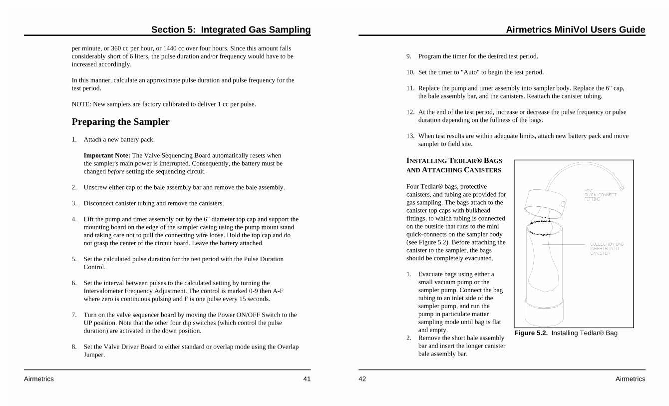
Four Tedlar® bags, protectivecanisters, and tubing are provided forgas sampling. The bags attach to thecanister top caps with bulkheadfittings, to which tubing is connectedon the outside that runs to the miniquick-connects on the sampler body(see Figure 5.2). Before attaching thecanister to the sampler, the bagsshould be completely evacuated.
1. Evacuate bags using either asmall vacuum pump or thesampler pump. Connect the bagtubing to an inlet side of thesampler pump, and run thepump in particulate mattersampling mode until bag is flatand empty.
2. Remove the short bale assemblybar and insert the longer canisterbale assembly bar.

Section 5: Integrated Gas Sampling
Airmetrics 43
Figure 5.3. Attaching Bag Canisters and Tubing
3. Slide canisters holding empty bags onto the bar and attach end caps.
4. Snap on bale handle.
5. Attach tubing from canisters to the mini quick-connect fittings on the sampler's
6" top cap (see Figure 5.3).
Airmetrics MiniVol Users Guide
44 Airmetrics
Integrated Gas Sampling Procedure
After the sampler has been assembled, the pulse frequency and duration correctlyestablished through a test run, and a fresh battery installed, the sampler is ready tocollect air samples at a field site. (See Figure G.2 insert at the end of this Manual fora sample Integrated Gas Field Data Sheet.)
NOTE: If a particulate sample is being collected simultaneously, refer to Section 4,“Particulate Matter Sampling” for proper particulate sampling procedure.
1. Transport the sampler to the field site. Verify that the sampler when installed inthe cradle will be positioned with the intake upward in an unobstructed area atleast 30 cm from any obstacle to air flow.
2. With the sampler on a firm level surface, unscrew either cap of bale assemblybar and remove bale assembly.
3. Detach canister tubing at mini quick-connect fittings and remove canisters.
4. Lift pump and timer assembly out by the 6" diameter top cap and support themounting board on the edge of the sampler casing, taking care not to pull theconnecting wire loose or jar the pump hose fittings. Hold the control assemblyby the top cap and do NOT grasp the circuit board.
5. Check that the Valve Driver Board is operational (Power Switch is in UPposition, Active Solenoid Output Indicators on).
6. Verify that all hose connections are secure. Check the pump by turning it on andthen off.
7. Select the desired mode of operation (standard or overlap) with the OverlapJumper. Make sure that the solenoid valves are plugged into the correct outputconnectors.
8. Use the Manual Sequence Advance Button to select the required channel.
Important Note: The Valve Sequencing Board automatically resets whenthe sampler's main power is interrupted. This is why the battery must bechanged before setting the sequencing circuit.

Section 5: Integrated Gas Sampling
Airmetrics 45
9. Program the on/off cycles for the desired sampling period (see page 9).
10. Press the ON/AUTO/OFF button once to set the timer to "Auto" mode. Thesampler must be in Auto mode before the operator leaves.
11. Place pump and timer assembly into sampler body. Replace bale assembly barand canisters, and connect tubing.
12. Using the hoisting pole, hook the bale and raise the sampler as vertically aspossible to the mounted mounting cradle (see Figure 4.4).
Gas Sample Retrieval
As soon as possible after the end of the sampling period, the operator should returnto the monitoring site to retrieve the filled bags. If a particulate sample is beingcollected simultaneously, refer to Section 4, “Particulate Matter Sampling” forproper particulate sample retrieval procedures.
Note: For a quick reference to the following steps, see Appendix C, "Integrated GasSampling Routine at Site."
1. Lower sampler from cradle using the hoisting pole. Positioned directly under thesampler, hook bale and lower away as vertically as possible. This vertical take-away is critical since the hook may dislodge or damage the rain cap or samplerhead. Also, the weight is more easily managed if the sampler is loweredvertically (see Figure 4.4).
2. With the sampler on a firm level surface, unscrew either cap of the baleassembly bar and remove bar assembly. Detach canister tubing at the miniquick-connect fittings and remove canisters.
3. Lift pump and timer assembly out by the top cap and rest on the edge of thesampler body, taking care not to pull the connecting wire loose. Hold the topcap. Do NOT grasp the circuit board.
4. Verify correct time and day of week on time LCD.5. Record elapsed time as shown on the elapsed time accumulator, which should
match the programmed time set at the beginning of the sampling period.
Airmetrics MiniVol Users Guide
46 Airmetrics
6. Check and record the fullness of the bag(s), adjusting the pulse interval orduration if necessary.
7. Program timer for new sampling period (see page 9).
8. Set to "Auto" mode.
9. Change battery pack (see page 28).
Important Note: The Valve Sequencing Board automatically resets whenthe sampler's main power is interrupted. This is why the battery must bechanged before setting the sequencing circuit.
10. Check the Active Solenoid Output Indicators to make sure that the desiredstarting channel has been selected. Use the Manual Sequence Advance Button toselect the required channel if necessary.
11. Lower pump and timer assembly into sampler body.
12. Replace bale bar assembly, attach new canisters, and connect tubing.
13. Using the hoisting pole, hook the bale and raise the sampler to the mountingcradle as vertically as possible.

Section 6: Hardware Description
Airmetrics 47
6 HARDWARE DESCRIPTION
Pneumatic System
PNEUMATIC SYSTEM FLOW SCHEMATIC
See Figure 6.1.
FILTER HOLDER ASSEMBLY
A 47 mm diameter filter cassette and filter holder assembly is used to hold the filtermedia.
FLOWMETER
A standard variable Flowmeter with a range of 1 to 10 lpm is used to indicatesampling flow rate. The uncalibrated accuracy of the flowmeter is ±4% of full scale.
FLOW CONTROL SYSTEM
A monitoring system designed by Airmetrics electronically controls pump speed tomaintain a specified flow setting by measuring the drop in air pressure at the outletof the flowmeter. The Flow Control System is temperature compensated forreasonable changes in ambient temperature and pressure.
MINIATURE BRUSHLESS D.C. DOUBLE ACTING DIAPHRAGM PUMP
The Double Acting Diaphragm Pump is powered by a Brailsford Type "T"magnetically commutated motor. The two pumping sections may be usedindependently, connected in parallel for increased flow or in series for higherpressure capacity. The unit is designed for 10 volt operation, but may be operatedfrom any voltage between 5 and 14 volts. Running speed varies between 2500 and3600 RPM depending upon the voltage and back pressure. Motor and crank pinbearings are double shielded, instrument type ball bearings lubricated for the life
Airmetrics MiniVol Users Guide
48 Airmetrics
Figure 6.1. Pneumatic System Flow Schematic
Section 6: Hardware Description
Airmetrics 49
of the unit. The pumping sections consist of synthetic rubber diaphragms housed inmolded plastic casing directly driven from the motor shaft by a scotch yoke-crankassembly. Valves are of the self-biasing fiberglass reinforced synthetic rubber type.No metallic springs are used in the blower. The air pumped contacts only the plasticand synthetic rubber areas. All moving parts are completely enclosed. The servicelife of the motor is in excess of 10,000 hours continuous duty. The diaphragm valveassemblies are easily replaceable. The service life expectancy of these assemblies area function of the environmental conditions, including the gases being pumped,delivery rate, and back pressure. Minimum service life for the pumping sections ison the order of 5000 or more hours continuous duty.
The motor generates no radio frequency interference and all electronic componentsare contained within the motor housing. Overall weight is 12.1 ounces (344 grams).
Electronics System
MOTHERBOARD
Virtually all sampler components connect to the motherboard--the pump,programmable timer, elapsed time totalizer, flowmeter, and flow controlcomponents. Flow control, intervalometer, and fault circuits, are built into this board,and pins are provided on the back side to mount the solenoid board for dual bagsampling.
POWER SUPPLY
The sampler is powered by removable battery packs which contain a 12 volt,12 amp-hour sealed lead-acid battery and a stepped output charger circuit. Thecharger circuit is powered by an 18 volt AC external power supply. The charger isdesigned to quick-charge the battery and then switch to a "maintenance" mode toavoid an overcharge condition. The charger can be left on for an indefinite periodwithout damaging the battery.
PROGRAMMABLE TIMER
The Programmable Timer can switch power on and off up to 6 times per day over a7-day period and is capable of individual or multi-day timer settings. It has an easyto read liquid-crystal display and its own power supply.
Airmetrics MiniVol Users Guide
50 Airmetrics
FLOW CONTROLLER CIRCUIT
The Flow Controller Circuit is designed to maintain a constant pressure drop acrossan orifice at the output of the flowmeter. Feedback from the pressure sensor is usedto control the pump speed by supplying variable voltage to the pump motor. Thesystem is temperature compensated and is capable of maintaining a constantvolumetric flow rate within ±5% of the set point over the range of 0 to 40°C.
ELAPSED TIME TOTALIZER
The Elapsed Time Totalizer is a non-resetable time totalizer which is activated whenthe programmable time controller is in the "ON" mode. The meter totals hours andtenths of hours.
INTERCONNECT BOARD
The Interconnect Board is located in the bottom of the sampler case. Power from thebattery pack is routed through banana pins on the outside of the sampler bottom tothe Interconnect Board. A phone plug in jack and cable is used to connect power tothe motherboard. A 2 amp fuse on the interconnect board provides protection to themotherboard from short circuits and high current loads.
MOTHERBOARD ELECTRONICS SCHEMATIC
See Figure G.3 insert at the end of this Manual.
BATTERY PACK CHARGER ELECTRONICS SCHEMATIC
See Figure G.4 insert at the end of this Manual.
VALVE DRIVER BOARD ELECTRONICS SCHEMATIC
See Figure G.5 insert at the end of this Manual.

Section 7: Maintenance
Airmetrics 51
7 MAINTENANCE
Ideally, records reflecting the history of maintenance (including all replacementparts, supplies, costs, expenditures) should be kept for each MiniVol, along with aninventory of on-hand spare equipment.
Check sheets should be used to record preventative and/or corrective maintenanceactivities and the subsequent sampler calibration curve.
The sampler is comprised of four basic components: preseparator/filter holderassembly, flow control system, timer, and battery pack. Following arerecommended, routine maintenance procedures for the sampler’s basic components.
Preseparator/Filter Holder Assembly
IMPACTOR CLEANING
The preseparator/filter holder assembly should be dismantled and the impactorcleaned and greased at regular intervals�i.e., every seventh sample to start, but ifheavy loadings are observed on the target disk, as often as appropriate.
1. Unmate the preseparator sections from the filter assembly and remove the raincap (see Figure 4.3 and 4.4).
2. Pushing with the thumb from the bottom, remove the impactor through top ofthe tube into the palm of your free hand.
3. Rinse the impactor from top to bottom with a solvent (hexane, white gas, lanterngas) using a squeeze bottle, paying particular attention to the impaction targetdisks. An acceptable alternative method of cleaning involves the use of anultrasonic bath with mild soapy water solution.
Impaction plates on the impactor(s) should be removed prior to regreasing. Theimpaction plate is attached to the impactor jet by spring tension only and may beseparated by simply pulling the jet from the impaction plate (see Figure 7.1).
Airmetrics MiniVol Users Guide
52 Airmetrics
Figure 7.1. Regreasing PM2.5 Impactor
4. Let the impactor air-dry.
5. Prepare a mixture of solvent andimpactor grease in a dropperbottle until thoroughly mixedand of a fluid consistency. Use a1-inch length of grease to 30 mlof solvent. Vigorously shake themixture until an opaque,uniform suspension, free fromgrease globs, is obtained.
Other low-vapor pressuregreases, such as silicone, areacceptable. However, removingthe dirty grease from theimpactor parts may be more difficult.
6. Put two or three drops of the cloudy solution on the target disk. The dropsshould saturate the disk, flowing freely to the edge.
7. Let the target disk "dry" by allowing the solvent to volatilize, leaving a thin filmof grease on the target disk.
8. Inspect the O-rings on the impactor for fitness and replace if necessary. O-ringsshould be coated with a thin film of silicone lubricant prior to use. Remove anyextraneous, loose, or hair-like shredded material from the exterior of theimpactor unit since this material could fall onto the filter below and causeerroneous gravimetric results. Carefully re-insert the impactor into the top of thepreseparator tube until the top of the impactor is flush with the top of the tube.
Flow Control System
Tubing, pulse dampener, and fittings must be routinely checked for crimps, cracks,or obstructions. Fittings should be inspected periodically for cross-threading andtightness. The flowmeter should be cleaned or replaced if it indicates no flow, lowflow, excessive flow, or erratic flow. The flowmeter can be easily cleaned usingwarm water and detergent; follow the steps below:

Section 7: Maintenance
Airmetrics 53
1. Remove the inlet and outlet tubing and detach the flowmeter from the maincircuit board.
2. Remove the flowmeter end caps and submerge in detergent solution. Sloshwater back and forth using the ball as a self-cleaning agitator. Follow with arinse in clean water.
3. Air dry and reinstall.
Programmable Timer
A single AA alkaline battery powers the programmable timer. It should last at least 6months. Since the clock and timer are sealed electronic devices, any failure requiresreplacement of the entire unit.
Battery Pack
Remove the battery pack top using a Phillips screwdriver and look for looseconnections. The battery charger board should be securely clamped to the bananajacks and the push on wire connectors securely attached to the battery. Tighten andclean any connections if corroded. The battery charging jack should be checked for asnug fit with charging transformer plug.
Cleaning/Inspecting Pump Valves and Diaphragms
After continued use, the pump valves and diaphragms will become dirty or worn.This condition usually manifests as an irregular flow rate or an inability to accuratelyadjust the flow rate. The pump may be unable to achieve or sustain a maximum flowrate (above 6 lpm). When these conditions occur, the pump valves must be cleanedor replaced. While the pump diaphragms are not usually affected by dirt, they willbecome worn and need replacement.
The side of the pump on which the valves are worn or dirty is easily determined bypinching the inlet tubes leading to the pump (first one side and then the other).Under normal conditions, the flow rate will drop by the same amount for both sidesas the lines are restricted. If the flow rate drops less for one side, the valves on thatside need cleaning or replacing.
Airmetrics MiniVol Users Guide
54 Airmetrics
When cleaning or replacing valves and diaphragms, replace or clean all valves anddiaphragms. (A "Double Diaphragm Pump Rebuild Kit" can be obtained fromAirmetrics.)
CLEANING/INSPECTING PUMP HEAD VALVES
1. Remove the pump head using a small Phillips head screwdriver. Beneath thepump head are two identical sets of three small circular rubber valve fittings (anO-ring, a white flapper valve, and a solid valve seat with a small diameter centerhole). Note that the flapper valve fits between the O-ring and the valve seat, andthat the two valve sets are inserted in reverse order to each other (i.e., on one setthe O-ring is on top, on the other the O-ring is on the bottom).
2. Carefully remove one set of valves using a pin or clip. Inspect each componentfor damage. Small cracks and imperfections can have a major impact on pumpperformance. Clean each valve part with a suitable silicone lubricant. Flip eachcomponent and replace in the same order. Repeat for the other valve set.
3. Screw on the pump head, taking care to match the alignment peg on the side ofthe pump head with its companion on the body of the pump.
4. Repeat for opposite side of the pump.
Section 8: Troubleshooting
Airmetrics 55
8 TROUBLESHOOTING
This section identifies common problems and the action necessary to correct them.
Problem Solution
The flowmeter will not zerowhen a leak check isperformed.
Prior to every sample run with the pumprunning, check for leaks by removing the inletassembly and covering the quick connect inletwith palm of the hand or a finger. The flowmetershould drop to zero. If not, a leak is present.Check all tubings and fittings for cracks andtightness. Check the pump nozzle connectionsand the flowmeter for cracks.
NOTE: when checking the fittings for tightnessDO NOT use a wrench or other tool to tightenthese connections. These fittings are made to befinger tightened. If a leak persists after fingertightening, replace the fitting.
A pump nozzle fitting hasbroken off.
Jam a small Phillips head screwdriver or tip ofpenknife blade into hole of broken fitting andturn out counterclockwise. Replace with a newfitting.
The charger light on top ofbattery fails to light whencharger is plugged in.
The charging LED on the top of the batteryshould light briefly even if the battery is alreadyfully charged. If the LED fails to light, either thetransformer is defective, the battery is defective,or the battery charger board inside the batterycase needs to be replaced.
1) Switch the transformer to the second batterypack. If the LED on this pack fails to light, thetransformer is probably defective. If you have asecond sampler, use the transformer from that
Airmetrics MiniVol Users Guide
56 Airmetrics
sampler to charge the batteries.
2) Disassemble the battery case using a Phillipsscrewdriver and connect the battery chargerboard to another battery. If the same conditionresults, the battery charger board is defective. Ifthe battery LED lights and the new batterycharges, the previous battery is defective.
The battery charger light onthe battery top does not turnoff after overnight charge.
The battery may be defective, as indicated by thecharger light remaining on "high charge" (i.e.,the battery fails to hold the charge and thecharger continues to charge). Connect a newbattery to the battery charger board. If the samecondition results, the charger board is defective.If the light turns off, the previous battery isdefective.
Battery voltage is less than 12volts after charging or thebattery will not power thesampler for a 24hr run.
1) Check the battery by connecting a volt-ohmmeter (VOM) to the negative and positivebattery terminals located on either side of thebattery charger light (the negative terminal isodd colored and located next to the samplercatch). If there is no voltage or the VOMreadings are intermittent, check that theterminals on the battery cover are tight. If not,see next step.
2) If there is still a voltage problem , remove thebattery pack top using a Phillips screwdriver andlook for loose connections. The battery chargerboard should be securely clamped to the bananajacks and connected securely to the battery.Tighten and clean any connections if corroded.Check the battery charging jack for a snug fitwith the charging transformer plug. Connect themeter directly to the internal battery terminals. Ifthere is still no or low voltage, see step 3.
Section 8: Troubleshooting
Airmetrics 57
NOTE: if loose or corroded connections werefound make sure the battery has received a fullcharge before proceeding with the next step.
3) Even if the VOM meter indicates the correctvoltage, perform the following check. Connect a12-volt light ( such as a automobile headlight )to the battery to simulate a load. Monitor thebattery voltage while connected to the simulatedload. The battery voltage should drop andstabilize somewhere between 11.5 and 12 volts.When the simulated load is disconnected thevoltage should return to approximately 12.5volts (within ±0.2 volt). If the battery fails tostabilize or does not recover to about 12.5 volts,the battery is most likely defective.
NOTE: make sure when performing these teststhe battery is charged and disconnected from thetransformer.
The flow rate cannot beaccurately adjusted using theFlow Rate Adjustment.
The pump valves and diaphragms are dirty orworn and need cleaning or replacing (see Section7, Maintenance, "Cleaning/Replacing PumpValves and Diaphragms").
Check the pulse dampener for cracks.
The flowmeter will not registera high flow rate ( 6 lpm orabove). There is no apparentrestriction or leak in theplumbing.
The pump valves and diaphragms are dirty orworn and need cleaning or replacing (see Section7, Maintenance, "Cleaning/Replacing PumpValves and Diaphragms").
Check the pulse dampener for cracks.
Bags do not fill consistently orsignificant adjustments tofrequency or pulse durationhave minimal effect.
The solenoid valve is leaking. The performanceof the solenoid valve can be determined byplacing a clear piece of tube from the outletfitting into a few inches of water and watching
Airmetrics MiniVol Users Guide
58 Airmetrics
for any back flow of water into the tube betweenpulses. If any backflow is present , check that thefittings are tight. If the problem persists, contactAirmetrics.

Appendix A: Calculating Flow Rate
Airmetrics 59
A SAMPLER FLOW RATE CALIBRATION
The MiniVol Portable Air Sampler is designed to operate at 5 lpm at ambientconditions. At the factory the sampler is calibrated at approximately 21°C at 754 mmHg, and is adjusted to operate at 5 lpm at these conditions. (See calibration curveshipped with sampler.) In other localities, the sampler must be adjusted to accountfor the different ambient temperature and barometric pressure. Adjustment within arange previously established by calibration is usually performed before everysampling project. This appendix explains how to use the calibration informationshipped with the MiniVol to determine the flow rate that will equal 5 liters/minute atlocal ambient conditions.
In the calibration procedure used by Airmetrics, the flowmeter is calibrated against aLaminar Flow Element (LFE) flow measuring device. Six flow rates, ranging fromapproximately 4 to 6 liters/minute, are typically measured. The inlet of the LFE isopen to the atmosphere while the outlet is attached to the inlet of the sampler. (Thesampler's filter assembly is not included in the air stream during the calibrationprocedure.)
Figure A.1 shows the results of a typical MiniVol calibration.
The columns in the table in Figure A.1 are defined as:
Qind Flowrate as indicated by the rotameter on the sampler.
Qact Flowrate at the actual calibration conditions as determined from the LFE.
Q@std The flowrate at standard conditions for the indicated LFE pressure drop.(Note that this is not the same as converting the actual flow rate to standardconditions.) Standard conditions are defined as an atmospheric pressure(Pstd) of 760 millimeters of mercury and a temperature (Tstd) of 298°K.
Qcalc The calculated flowrate of the sampler that is determined from the linearregression results.
Diff The percentage difference in flow rates between the measured and the
Airmetrics MiniVol Users Guide
60 Airmetrics
Q m Q bstd vo l ind vo l@ = × + (1)
calculated flow rates.
For each point in the calibration procedure, the flow rate indicated by the flowmeter,"Qind", is recorded, and the actual flow rate, “Qact” and “Q@std” are calculatedfrom the pressure drop across the LFE.
The flow rate units "lpm" are liters per minute.
The Linear Regression Results in Figure A.1 shows the results of the best fitline of Qind (independent) to Q@std (dependent) variables:
where mvol = slope of the least square linebvol = intercept the least square line
The variance (r2) is also listed in Figure A.1.

Appendix A: Calculating Flow Rate
Airmetrics 61
Figure A.1. Portable Sampler Calibration Output
Airmetrics MiniVol Users Guide
62 Airmetrics
P PE
act sea= × −
1
1 4 5 3 3 0
5 25.
(2)
Sampling at Ambient Conditions
The MiniVol's size-selective inlet is an impactor whose particle size selectioncharacteristic is dependent upon the velocity with which the air stream impacts uponthe impaction plate. The impactor is designed to have a nominal 10µm (part 206-000) or 2.5µm (part 206-100) cut off at an actual air flow rate of 5.0 liters perminute. To maintain this cut off size, the sampler’s flow rate must be adjusted(flowmeter set point - Isp) so that the flow rate through the size-selective inlet ismaintained at 5.0 lpm at ambient conditions.
To calculate the flowmeter set point, you need:
• the sampler’s calibration slope, mvol, and intercept, bvol. This information issupplied to you on the “MiniVol Portable Sampler NIST Traceable FlowCalibration” that came with your sampler (Figure A.1);
• the expected ambient temperature, Tact, in K°, and pressure, Pact, in mm Hg,expected during the sampling study. This data may be estimated from localweather service data or from other reported historical data. If the U.S WeatherService atmospheric pressure is used, be sure that the “station pressure” is used.That is, atmospheric pressure not corrected for the reporting site’s elevationabove sea level.
If the local “station pressure”, Pact is not readily available, it can be reasonablyestimated by using Equation 2.
Where Pact = ambient atmospheric pressurePsea = sea level atmospheric pressure (nominally 760 mm Hg)E = site elevation in feet
The Flowmeter Set Point, Isp, is calculated using Equation 3.
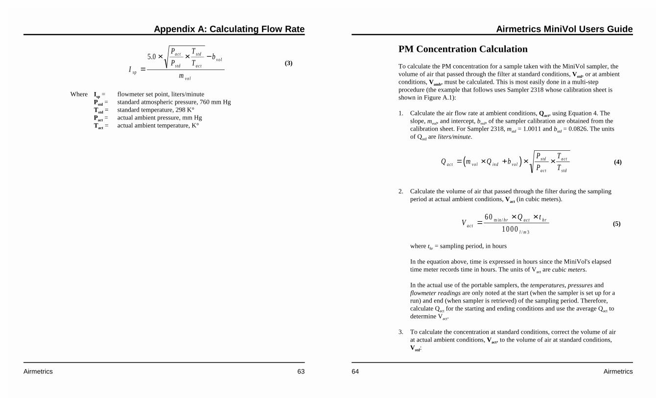
Appendix A: Calculating Flow Rate
Airmetrics 63
I
P
P
T
Tb
msp
a c t
s td
std
a c tv o l
v o l
=× × −5 0.
(3)
Where Isp = flowmeter set point, liters/minutePstd = standard atmospheric pressure, 760 mm HgTstd = standard temperature, 298 K°Pact = actual ambient pressure, mm HgTact = actual ambient temperature, K°
Airmetrics MiniVol Users Guide
64 Airmetrics
( )Q m Q bP
P
T
Ta c t v o l in d v o ls td
a c t
a c t
s td
= × + × × (4)
VQ t
a c th r a c t h r
l m
=× ×6 0
1 0 0 0 3
m in /
/
(5)
PM Concentration Calculation
To calculate the PM concentration for a sample taken with the MiniVol sampler, thevolume of air that passed through the filter at standard conditions, Vstd, or at ambientconditions, Vamb, must be calculated. This is most easily done in a multi-stepprocedure (the example that follows uses Sampler 2318 whose calibration sheet isshown in Figure A.1):
1. Calculate the air flow rate at ambient conditions, Qact, using Equation 4. Theslope, mvol, and intercept, bvol, of the sampler calibration are obtained from thecalibration sheet. For Sampler 2318, mstd = 1.0011 and bstd = 0.0826. The unitsof Qstd are liters/minute.
2. Calculate the volume of air that passed through the filter during the samplingperiod at actual ambient conditions, Vact (in cubic meters).
where thr = sampling period, in hours
In the equation above, time is expressed in hours since the MiniVol's elapsedtime meter records time in hours. The units of Vact are cubic meters.
In the actual use of the portable samplers, the temperatures, pressures andflowmeter readings are only noted at the start (when the sampler is set up for arun) and end (when sampler is retrieved) of the sampling period. Therefore,calculate Qact for the starting and ending conditions and use the average Qact todetermine Vact.
3. To calculate the concentration at standard conditions, correct the volume of airat actual ambient conditions, Vact, to the volume of air at standard conditions,Vstd:

Appendix A: Calculating Flow Rate
Airmetrics 65
V VP
P
T
Tstd a cta ct
s td
std
a ct
= ×
×
(6)
[ ]P MM
Va c tP M
a c t
= (7)
[ ]P MM
VstdP M
std
= (8)
4. To finally calculate the concentration of PM, divide the net mass gain of thefilter by the volume of air that passed through the filter.
or
where [PM]act = PM concentration, in µgrams per cubic meter (actual) [PM]std = PM concentration, in µgrams per cubic meter (standard) MPM = Mass of particulate matter collected on the filter, in
µgrams
Airmetrics MiniVol Users Guide
66 Airmetrics
This page was intentionally left blank.

Appendix B: Gravimetric Analysis Procedure
Airmetrics 67
B GRAVIMETRIC ANALYSIS PROCEDURE
Introduction
The low loadings of particulate matter caught on the filter medium by the MiniVolsampler necessitate special handling and weighing techniques. The preparation ofthe filters for sampling and the handling after return from the field have become soclosely geared to the gravimetric operations involved in mass determination that theprocedure is best considered as a single topic. Thus the sections to follow are dividedby variations in samplers or filter types rather than by operation.
Apparatus and Supplies
Listed here are the general equipment and space requirements for filter handling andmass determination.
1. Weighing table should be desk height, sturdy and vibration free, with a smooth,easily-cleaned surface; and equipped with a comfortable chair, preferablyadjustable in height, with swivel and rollers. This working area must be in anenvironment that is away from air currents and experiences minimaltemperature and humidity changes, and is substantially free of dust or othercontaminants.
2. Microbalance. We use a Cahn Model C-32 Electrobalance which has a capacityof 1.5g, and sensitivity of 0.1µg.
3. A class S 200 mg weight certified by the State Metrology Lab, and thustraceable to National Institute for Standards and Technology (NIST), is used asa primary calibrating standard.
4. Weight handling forceps with smooth plastic tips.
5. Hygrometer, Abbeon wall mounting dial-type, accurate to ±3%.
6. Thermometer. Celsius, with resolution to 0.5 degrees and range over normalroom temperatures.
Airmetrics MiniVol Users Guide
68 Airmetrics
7. Staticmaster ionizing units. One is centered in balance chamber, anothermounted conveniently on stand near balance.
8. Filter handling forceps and spatula both should be of non-magnetic stainlesssteel with rounded edges and smooth surfaces.
9. Tackle boxes modified to contain a base platform fitted with quick disconnect(female) fittings to transport sampling materials.
10. Field data sheets.
11. Petrislides, Millipore®, 47mm.
Filters and supplies for each type of sampling are listed in the appropriate section tofollow.
General Instructions for Microbalance
A. The balance must be turned on and allowed to warm up for a minimum of 30minutes. Six hours warm up is recommended by the manufacturer for maximumstability. Since we use the balance daily, it is convenient to leave it on continu-ously.
B. Handle Class S weights with care and store each in its individually-marked box.They should be handled only with plastic or bone-tipped forceps, since steel willscratch the surfaces. The forceps should not be used for any other purpose.Particular care must be exercised to prevent contamination by dirt or anythingwhich could cause oxidation, since the weights can change significantly withoutapparent deterioration.
C. Adhere to a cleaning schedule. The bench top and working surfaces should bedusted daily. All equipment and supplies in the working area should beremoved, and they and the chamber interior cleaned weekly at minimum.NOTE: Do not use freon-type pressure dusters in or around the chamber.
D. The following procedure is followed to set up the balance for each filterweighing session:
1. Set the balance to operate in the 250 mg range. 47mm quartz or Teflon®

Appendix B: Gravimetric Analysis Procedure
Airmetrics 69
filters typically weigh approximately 150 mg.
2. With nothing on the pans, press the "Tare" button on the balance after thereading has stabilized to zero the balance.
3. Place the 200 mg Class S weight on the balance. After the reading hasstabilized, calibrate the balance by pressing the "Calibrate" button.
4. Remove the calibration weight from the sample pan.
5. The balance is now ready for weighing.
E. Record each use of the microbalance in its log book.
F. Every three months, or when conditions warrant, check the working calibrationweight against a second certified 200 mg weight whose value is traceable toNIST.
The purpose of our routine checks against the certified weight is to detect anychanges in the working standard due to wear, dirt, or other damage. Record allsteps of the procedure carefully in the balance log book. Also record barometricpressure, temperature, and relative humidity. Zero and calibrate the balance withthe working standards; then weigh the certified weight and record the value.Repeat twice to provide three comparative values.
G. Data from procedure F above should be reviewed periodically to assure that tareand calibration values do not change without detection. Since our primaryinterest is in weight differences between clean and loaded filters, the absolutevalue of the balance tare is not as critical as the constancy of the value. Thus it isextremely important that frequent checks be performed to monitor changes inthe calibration weights.
Following the long-term trends of calibration weighings can furnish informationabout the calibration standards.
H. Precision and Accuracy
A measure of the precision of the microbalance has been obtained by repetitiveweighings over a four-month period of the series of substitute weights. A total
Airmetrics MiniVol Users Guide
70 Airmetrics
of 75 measurements made on six different weights resulted in a range of ±1microgram on the 200 milligram range, which is the range used in filterweighing. This is in agreement with the manufacturer's stated precision as apercent of sample load for a 200 mg range.
Repetitive weighing actually reflects the precision of the microbalance and theweights combined. Although the class S metal weights are reasonably stable andconstant, they are subject to environmental factors such as air buoyancy andtemperature and to corrosion, dirt, and handling damage.
Accuracy is defined as the agreement of a balance reading with the true samplemass. The balance accuracy is limited by digital voltmeter linearity, torquemotor linearity, precision, and range agreement. As a percent of electrical range,Cahn specifies the microbalance accuracy is ±0.005%.
The principal uncertainty is not in the balance, but in the calibration weights.The Oregon State Metrology Laboratory states the overall uncertainty for ourprimary certified weight as ±12 micrograms.
On the 250 mg range, the total uncertainty of the system becomes ±14micrograms. This figure can be used as the uncertainty in an apparent valuedetermination after the corrections discussed earlier.
In weighing as performed on membrane filters, the uncertainties associated withthe weights are assumed to cancel out because of the calibration procedures; butadditional errors are introduced by the properties of the filters and the handlingprocedures. Tracking of these errors is discussed in the section detailing eachsampling method.
Low Volume Suspended Particulate Matter
A. Equipment and Supplies
1. Filters--Quartz Microfibre (QM-A) 47 mm, manufactured by WhatmanCorporation, catalog no. 1851-047.
2. Filter Holders--Nuclepore Corp. Aerosol Holder, 47 mm Stock No. 430200.
3. Multiple holder adapters, 47 mm Nuclepore Stock No. 470400, 8 per
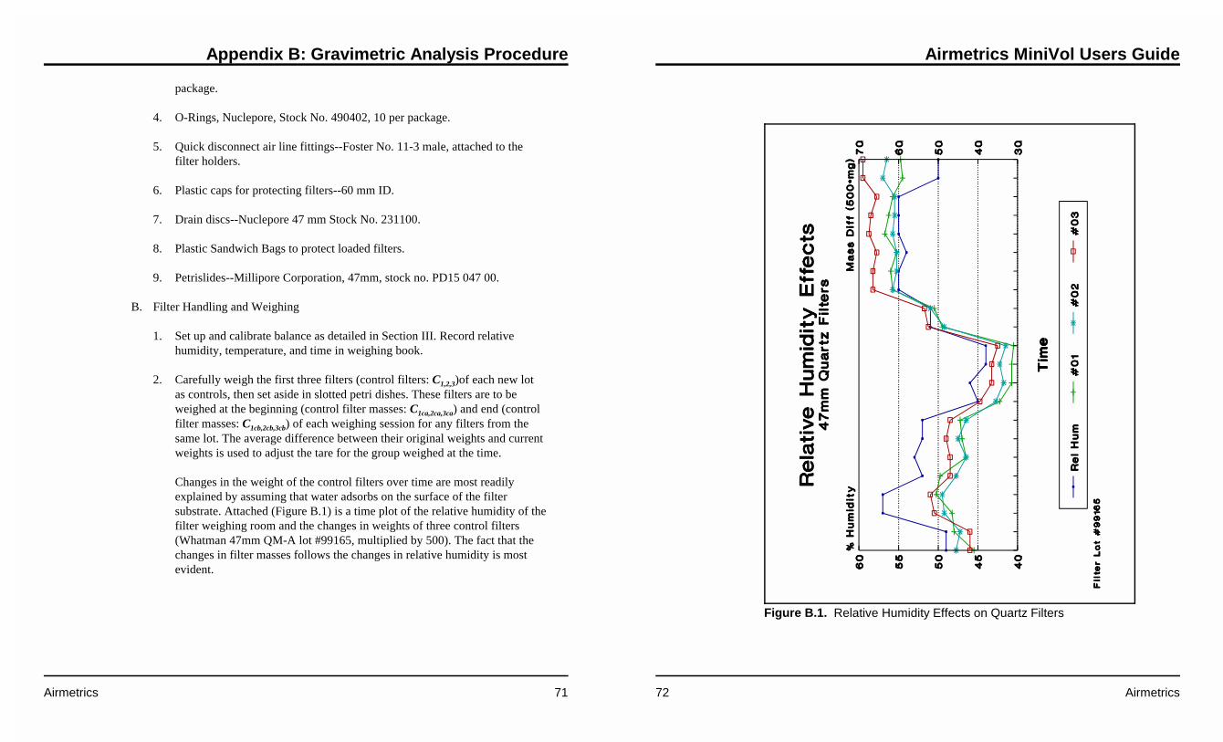
Appendix B: Gravimetric Analysis Procedure
Airmetrics 71
package.
4. O-Rings, Nuclepore, Stock No. 490402, 10 per package.
5. Quick disconnect air line fittings--Foster No. 11-3 male, attached to thefilter holders.
6. Plastic caps for protecting filters--60 mm ID.
7. Drain discs--Nuclepore 47 mm Stock No. 231100.
8. Plastic Sandwich Bags to protect loaded filters.
9. Petrislides--Millipore Corporation, 47mm, stock no. PD15 047 00.
B. Filter Handling and Weighing
1. Set up and calibrate balance as detailed in Section III. Record relativehumidity, temperature, and time in weighing book.
2. Carefully weigh the first three filters (control filters: C1,2,3)of each new lotas controls, then set aside in slotted petri dishes. These filters are to beweighed at the beginning (control filter masses: C1ca,2ca,3ca) and end (controlfilter masses: C1cb,2cb,3cb) of each weighing session for any filters from thesame lot. The average difference between their original weights and currentweights is used to adjust the tare for the group weighed at the time.
Changes in the weight of the control filters over time are most readilyexplained by assuming that water adsorbs on the surface of the filtersubstrate. Attached (Figure B.1) is a time plot of the relative humidity of thefilter weighing room and the changes in weights of three control filters(Whatman 47mm QM-A lot #99165, multiplied by 500). The fact that thechanges in filter masses follows the changes in relative humidity is mostevident.
Airmetrics MiniVol Users Guide
72 Airmetrics
Figure B.1. Relative Humidity Effects on Quartz Filters

Appendix B: Gravimetric Analysis Procedure
Airmetrics 73
Because the sample filters (both clean and exposed) are "conditioned" in thesame room as the control filters, we assume that the relative humidityaffects the sample filters to the same extent as the control filters.
Note: the Cahn C-32 Electrobalance mass units are in milligrams. All filtermasses are, therefore, recorded in milligrams.
3. Handle filter (sample filters: F) with stainless forceps and spatula. Passfilter through field of static eliminators for a few seconds, then center onbalance pan. Close door.
4. Read and record the clean sample filter weight (clean masses: Fc) onlywhen microbalance readout remains steady for a minimum of 20 seconds. Iffilters have been equilibrating and the room relative humidity and tempera-ture have been fairly constant for a few hours, this should not require over aminute or two. If the readout continues to drift for excessive time, it may benecessary to put off weighing until equilibration of the filters is complete orthe room conditions stabilize.
5. After recording the weight, load the filter in a holder above a drain disc,fasten a numbered label to the holder, then cover with a sandwich bagtopped by a plastic cap. Loaded holders are stored upright in racks toprevent contamination.
Filters to be shipped or stored in bulk for special projects are loaded intoPetrislides with two numbered labels attached. When these filters are loadedinto holders, one label is attached to the holder as above, and the otherremains with the Petrislide so the exposed filter can be returned to thecorrect slide.
6. Generally, filters are sent to the field loaded into a tackle box fitted withquick disconnect fittings. Field sampling reports or data sheets are sent witheach filter or set of filters (Figure 3).
7. Filter heads or Petrislides received from the field are first checked againstthe accompanying field sampling report for correct numbers, site and flowinformation, then the plastic bags are removed and holders are placedupright on racks for equilibration. The receiving date is logged on the fieldreport.
Airmetrics MiniVol Users Guide
74 Airmetrics
8. After a minimum of 24 hours equilibration, weigh each exposed samplefilter (exposed masses: Fe) as in 1, 2, and 3 above, making certain the threecontrol filters for each pertinent lot are reweighed (control filter massesbefore weighing exposed sample filters: C1ea,2ea,3ea, and after sampler filterweighing: C1eb,2eb,3eb) at the same time.
9. Store weighed samples in 47 mm Millipore® Petrislides with ID numberattached.
C. Calculations and Reporting
1. The gross mass of particulate matter on the sample filter (Wg) is found bysubtracting the exposed filter mass from the clean filter mass:
The change in the weighs of the control filters between the clean andexposed sample filter weighings (��C) is calculated:
where n is the number of control filters used. While it is recommended thatthree control filters be used, on occasion a control filter will becomeunusable (soiled, torn, or otherwise damaged). In these instances thenumber of available control filters will be less than three.
The net mass of particulate matter on the filter (Wn) is obtained by correct-ing the gross mass for the mass change of the control filters:
These calculations and Wn, the filter sample or loaded weight, are recordedin the appropriate filter weighing log book.
2. The field sampling report is used to calculate the air volume and sample

Appendix B: Gravimetric Analysis Procedure
Airmetrics 75
time using the lab portion below the dashed line. Start and stop air flows areread from the latest calibration plot for the orifice used for the vacuumreading. Average flow in liters per minute is the mean of the start and stopflow conversions.
The sample time (t) is ordinarily the difference between the start and stopreadings from a time totalizer. It is convenient to record time in minutes,the unit used for flow, to simplify the calculations.
Sample air volume (V), in cubic meters, is then the average flow (Q), inliters per minute, times the sample time, in minutes, times 0.001, theconversion from liters to cubic meters.
3. The information from the field sampling report and weights from the filterweighing book are entered in the sample log book. Data run assumesmidnight-to-midnight samples; if otherwise, the times and dates must beclearly indicated. Date received is when logged into the lab. The station isindicated by AIRS/SAROAD number. Sampler and filter numbers arecopied from the field report. Type refers to filter medium, in this caseWhatman QM-A Quartz Microfibre. Configuration indicates the kind ofsample, in this case TSP or PM10. Orifice number, average flow, and airvolume (V) are entered from the field report. Finally, the particulate matterconcentration (PM) in micrograms per cubic meter is found by the formula:
where the "1000" is the conversion factor from milligrams to micrograms.
4. Final concentration data is reported to AQC in the AIRS/SAROAD formatfor entry in the appropriate data base.
5. A sample day station summary is compiled for all sites listing filternumbers and air volume. The information is needed to cross referencesamples by date and station. The sheet is also used to record voids, samplelosses and other problems. Once this sheet is completed, the field sampling
Airmetrics MiniVol Users Guide
76 Airmetrics
report may be filed.
6. The computer program used to calculate particulate matter concentrationsfrom portable saturation samplers has expanded data flagging and calcula-tion features which allow for equipment limitations and data qualityassumptions appropriate for survey sampling.
a. Concentration calculations can be performed, and flagged with a codesdenoting data limitations or assumptions included in the calculations. Alisting of commonly used codes is presented below.
M: Missing field dataB: Battery failureF: Flow differentialT: Timer malfunctionS: Sampler malfunctionD: Damaged filter
b. The sampler flowrate differential flag (F:) is computer-generated, andis attached to the calculated concentration if the pre- and/or post-flowsare outside ± 15% of the samplers "ideal flow setpoint". In this case thepre-flow is used to calculate the particulate matter concentration.
c. Sometimes, a final flow is not available due to battery failure of theportable sampler. In this case, a "B:" code is assigned to the data, and apost flow equal to the pre-flow is used to calculate the concentration.This provides some assurance that the actual flowrate will be overesti-mated, and the resultant concentration biased lower.
d. The other codes are assigned based on comments made on field datasheets, or observations of the filters during post weighing procedures.Flagged data and comments are included in the printed calculations,and printed in tabular form appended to the project data summary.
D. Quality Control and Assurance
1. At least a 7% level of blanks shall be set aside during preparation of filters
Appendix B: Gravimetric Analysis Procedure
Airmetrics 77
for sampling. The blank is weighed, assigned a number in sequence withthe other filters being tared, then placed in a labeled petri dish. The codeletter B is prefixed to the filter number in the weighing book and on thepetri dish label. The blanks serve several functions:
a. As a quality control on the gravimetric procedure, each blank isreweighed at least one day after the initial weighing. At least 50% ofreweighs should be performed by someone other than the originaltechnician. The weight variations in a statistically significant number ofsuch audits are then used to establish control limits for the variation atthree standard deviations (see Quality Assurance Handbook for AirPollution Measurement Systems, Vol. 1, Appendix H). Control limitsshould be recalculated every six months from the most recent blankvalues. If a blank shows variation between weighings beyond thecontrol limits, the weighing process must be rechecked and, if thediscrepancy is not found to be associated with the second weighing, allthe filters tared with the initial blank weighing must be rechecked.
b. Blanks are selected with samples of the same lot as analysis blanks forion chromatography, X-ray spectrometry, or other tests.
c. Blanks may occasionally be needed to replace damaged control filtersfor temperature/humidity adjustments.
d. Unused blanks or portions thereof are stored in numerical order withtheir samples for at least two years before discarding.
2. Since it is known that humidity and temperature introduce most of thevariability in filter weights, close control must be maintained on thesefactors. Any change of 1% in humidity or of one degree celsius in tempera-ture during a weighing session necessitates the reweighing of the controlsand recalculation of the adjusted tare.
3. The three control filters furnish another quality check on the weighingprecision and on the accuracy of the tare adjustment. The variations in �Cbetween the controls are compared to control limits established from thepast performance of the filters--such limits are set at three standarddeviations as in 1a, above. When excess variation indicates an out-of-control condition, weighing must be suspended until the balance is checked
Airmetrics MiniVol Users Guide
78 Airmetrics
and recalibrated and the control filter reweighed.
4. Zero the balance after every twenty filter weights. Reset the zero if needed.(Caution: Large position zero displacements may be caused by dirt on thepan. Remove the pan, clean it, and then recheck the zero in such cases. Ifthe zero drift at any check is over one microgram, reset it and then recheckthe calibration before continuing. If the zero drift is over five micrograms,correct the balance and reweigh filters back to the point where thedifference is two micrograms or below.)
5. Special short-term sampling projects usually require more rigorous QA togenerate better P&A statistics over a shorter time period. In these studies itis common to perform filter reweigh checks on both clean and exposedfilters at the 10-15% level.

Appendix C: Quick Reference
Airmetrics 79
C QUICK REFERENCE
Particulate Matter Sampling Routine at Site
Note: Perform as much work as possible inside a vehicle (disassembling sampler,checking for leaks, replacing filter, etc.), particularly if the weather is rainy, windy,or snowy.
1. Hoist the sampler down from the mounting cradle, keeping the hoisting pole asvertical as possible to avoid dropping the sampler or damaging thepreseparator/filter holder assembly with the hook.
2. Inside the vehicle, remove the bale bar assembly and handle.
3. Remove the timer and pump assembly by grasping the 6" lid, taking care not todisconnect power cord from battery. Do NOT grasp center of circuit board.Mount the assembly on the edge of the sampler casing using the pump mountstand. Leave the battery attached.
4. Record the hours shown on the elapsed time totalizer.
5. Press the Timer On/Auto/Off button to start pump.
Error: If a RED LIGHT is lit (either low flow or low battery), press the Resetbutton to start pump.
6. With the sampler held vertically, read the flowmeter (to the nearest tenth atcenter of ball) and record the ending flow rate.
7. Lower assembly back into tube.
8. Before removing the preseparator/filter holder assembly from sampler, cross-check the filter sticker number on the assembly against the filter number for thatsite on the worksheet. These numbers should match. If not, make a note of this,recording the actual filter number.
Airmetrics MiniVol Users Guide
80 Airmetrics
9. Remove the preseparator/filter holder assembly at the quick-connect and place itin clean plastic bag for transport back to lab.
10. Change the battery pack. (Do not inadvertently confuse and reuse the spentbattery.) If either the low or low voltage indicator was lit, make a note that thespent battery may be defective.
11. Check the sampler for leaks. Remove the pump and timer assembly from thesampler body, start the pump by pressing the On/AUTO/Off button, and coverthe inlet with palm. The ball should drop to the bottom of the flowmeter. If itdoes not, check/tighten all tubing, joints, and quick-connect fittings until thesampler is leak-free.
12. Attach a new preseparator/filter holder assembly containing a new filter at thesampler quick-connect.
13. If the low flow indicator was lit, check for crimps or air restrictions in the inletor tubing.
14. On a new Field Data Log worksheet, record site #, sampler #, battery #, and newfilter #.
15. With the sampler running and while holding it vertically, adjust the flow rate tothe correct level. Record the beginning flow rate to the nearest tenth ofliter/minute.
16. Turn the pump off by pressing ON/AUTO/OFF button.
17. Record hours shown on the Elapsed Time Totalizer.
18. Program the Programmable Timer.
19. Lower the pump and timer assembly into the sampler body and reinsert the baleassembly bar..
20. Return the sampler to the mounting cradle, raising it as vertically as possible.
21. If also doing gas sampling, see the following Integrated Gas Sampling Routine.

Appendix C: Quick Reference
Airmetrics 81
Integrated Gas Sampling Routine At Site
Note: Perform as much work as possible inside a vehicle (disassembling sampler,replacing canisters, etc.), particularly if the weather is rainy, windy, or snowy.
1. Lower sampler from its cradle mount, keeping the hoisting pole as vertical aspossible to avoid dropping the sampler or damaging the preseparator/filterassembly with hook.
2. Inside the vehicle remove the bale bar assembly. Detach canister tubing at themini quick-connect fittings and remove canisters.
3. Remove the pump and timer assembly, taking care not to pull the connectingwire loose. Hold the top cap. Do NOT grasp the circuit board. Mount theassembly on the sampler casing using the triangular mount stand.
4. Verify correct time and day of week on time LCD.
5. Record elapsed time as shown on the Elapsed Time Totalizer, which shouldmatch the programmed time.
6. Check and record the fullness of the bag(s), adjusting the pulse interval orduration if necessary.
7. Program the timer for new sampling period (see page 9).
8. Set to "Auto" mode.
9. Change battery pack (see page 28).
IMPORTANT NOTE: The Valve Driver Board automatically resets whenthe sampler's main power is interrupted. This is why the battery must bechanged before setting the sequencing circuit.
10. Check the Active Solenoid Output Indicators. Use the Manual SequenceAdvance Button to select the required channel if necessary.
11. Lower the pump and timer assembly into the sampler body.
Airmetrics MiniVol Users Guide
82 Airmetrics
12. Replace the bale bar assembly, attach new canisters, and connect tubing.
13. Return the sampler to the mounting cradle, raising it as vertically as possible.
14. If also doing particulate matter sampling, see the preceding Particulate MatterSampling Routine.

Appendix D: Warranty Policy
Airmetrics 83
D WARRANTY POLICY
What is Covered
The MiniVol Portable Air Sampler is warranted by Airmetrics against defects inmaterials and workmanship for one year from the date of original purchase. If yousell your unit or give it as a gift, the warranty is automatically transferred to the newowner and remains in effect for the original one-year period. During the warrantyperiod, we will repair or, at our option, replace at no charge a sampler that proves tobe defective, provided you return the sampler, shipping prepaid, to Airmetrics.(Replacement may be with a newer model of equivalent or better functionality.)
This warranty gives you specific legal rights, and you may also have other rights thatvary from state to state, province to province, or country to country.
What is Not Covered
AA batteries, and damages caused by AA batteries, are not covered by theAirmetrics warranty.
This warranty does not apply if the product has been damaged by accident or misuseor as the result of service or modification by other than an Airmetrics technician.
No other express warranty is given. The repair or replacement of a product is yourexclusive remedy. Any other implied warranty of merchantability or fitness islimited to the one-year duration of this written warranty.
Some states, provinces, or countries do not allow limitations on how long an impliedwarranty lasts, so the above limitation may not apply to you. In no event shallAirmetrics be liable for consequential damages. Some states, provinces, or countriesdo not allow the exclusion of limitation of incidental or consequential damages, sothe above limitation or exclusion may not apply to you.
Warranty on Service
Airmetrics MiniVol Users Guide
84 Airmetrics
Service is warranted against defects in materials and workmanship for 90 days fromthe date of service.
Service Agreements
In the US., a support agreement is available for repair and service. For additionalinformation, contact:
Airmetrics2121 Franklin Boulevard, #9Eugene, Oregon 97403U.S.A.(541) 683-5420

Appendix E: Replacing Damaged/Defective Components
Airmetrics 85
E REPLACING DAMAGED/DEFECTIVECOMPONENTS
In the event that a MiniVol Portable Air Sampler component is missing, damaged, ordefective, follow these steps to obtain a replacement part:
� Call Airmetrics tech support and explain the problem. . . .(541) 434-9695.
� Obtain authorization to return the defective or damaged components.
� Package the item(s) carefully to prevent further damage.
� Identify the item(s) being returned on a clearly marked packing list with yourname, company name, address, and phone number.
� Ship to our shop address:
Airmetrics2121 Franklin Blvd., #9
Eugene, OR 97403U.S.A.
(541) 683-5420
� Items will be repaired/replaced and returned as soon as possible.
Airmetrics MiniVol Users Guide
86 Airmetrics
This page was intentionally left blank.

Appendix F: Parts List
Airmetrics 87
F PARTS LIST
The following Figures and Tables identify the components and parts of the MiniVolsampler.
Airmetrics MiniVol Users Guide
88 Airmetrics
Figure F.1. Main Circuit Board Parts Identification.

Appendix F: Parts List
Airmetrics 89
Main Circuit Board Card(see Figure F.1)
P/N Description
101-000 Main Circuit Board Card (w/o Pump and Flowmeter)
101-001 Elapsed Time Totalizer
101-002 Programmable Timer
101-005 Mounting Bracket
101-008 Pressure Sensor
101-009 Flowmeter Outlet/Orifice Fitting
101-010 Flowmeter Inlet Fitting
101-010-01 Poly Insert, 5/16"
101-011 Pulse Dampener
101-012 Inlet Filter
101-013 Plastic Y-connector, 3/16"
101-014 Inlet Hose Barb Fitting, 1/4" MNPT × 3/16" ID Hose
101-015 Flat Washer, s/s, 9/16" SAE
101-003 Flowmeter, 0-10 LPM
102-000 Pump, Dbl Diaphragm, 8-12 V
102-001 Pump Hose Barb Fitting, 1/4-28 × 3/16" ID Hose
102-002 Pump Mounting Bracket
102-006 Pump Rebuild Kit, 2-head
102-006-01 Pump Diaphragm, Neoprene
102-006-02 Pump Valve
Airmetrics MiniVol Users Guide
90 Airmetrics
Figure F.2. Valve Driver Board Parts Identification
102-006-03 Pump Valve Seat, Viton
102-006-04 Pump Valve O-Ring, Silicone
101-019 Pump Mount Stand, Aluminum
101-020 Ethafoam Shipping Block
101-022 Flat Washer, 5/8" SAE, s/s

Appendix F: Parts List
Airmetrics 91
Valve Driver Board(see Figure F.2)
P/N Description
103-000 Complete Valve Driver Board
103-001 Valve Driver Circuit Board
103-002 Solenoid Valve
103-003 Solenoid Output/Orifice Fitting, 10-32 × 1/8" ID Hose
104-001 Panel Mount Mini Quick Connect, male
104-011 Female Mini Quick Connect
Airmetrics MiniVol Users Guide
92 Airmetrics
This page was intentionally left blank.
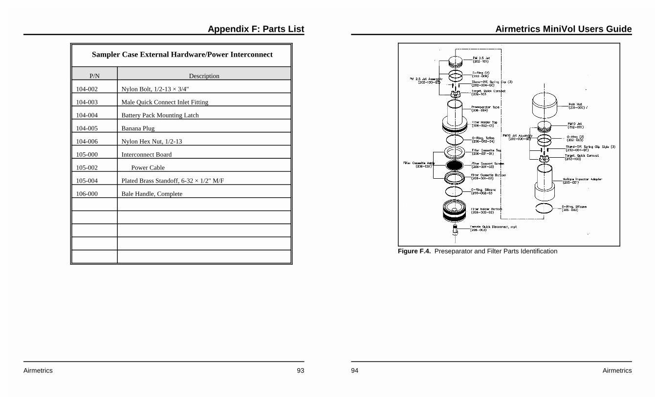
Appendix F: Parts List
Airmetrics 93
Sampler Case External Hardware/Power Interconnect
P/N Description
104-002 Nylon Bolt, 1/2-13 × 3/4"
104-003 Male Quick Connect Inlet Fitting
104-004 Battery Pack Mounting Latch
104-005 Banana Plug
104-006 Nylon Hex Nut, 1/2-13
105-000 Interconnect Board
105-002 Power Cable
105-004 Plated Brass Standoff, 6-32 × 1/2" M/F
106-000 Bale Handle, Complete
Airmetrics MiniVol Users Guide
94 Airmetrics
Figure F.4. Preseparator and Filter Parts Identification

Appendix F: Parts List
Airmetrics 95
Preseparator and Filter Holder Assembly(see Figure F.4)
P/N Description
206-000 PM10 Preseparator/Cassette Filter Holder Assembly, Complete
206-100 PM2.5 Preseparator/Cassette Filter Holder Assembly, Complete
206-001 Filter Cassette, FRM Style, Complete
206-001-03 Filter Support Screen/drain disk
206-002 Filter Holder Assembly, Grey, no tube, disconnect
206-002-01 Filter Holder, Top
206-002-02 Filter Holder, Bottom
206-002-03 O-Ring for Top, Teflon
206-002-04 O-Ring for Bottom, Viton
206-003 Quick Disconnect, 1/4" mpt, female
206-004 Preseparator Tube, Grey
201-000 PVC Rain Hat
202-000-QC Impactor, PM10, QC, Complete
202-001 Jet, PM10
202-004-QC Stand-Off, Spring Clip Style
202-103 Impaction Plate, Quick Connect
202-003 O-Ring, PM10, Silicone, Red
202-100-QC Impactor, PM2.5 QC, Complete
202-101 Jet, PM2.5
202-004-QC Stand-Off, Spring Clip Style
Airmetrics MiniVol Users Guide
96 Airmetrics
202-103 Impaction Plate, Quick Connect
202-003 O-Ring, PM2.5, Silicone, Red
205-001 Multiple Impactor Adapter, Grey
205-002 O-Ring for Adapter
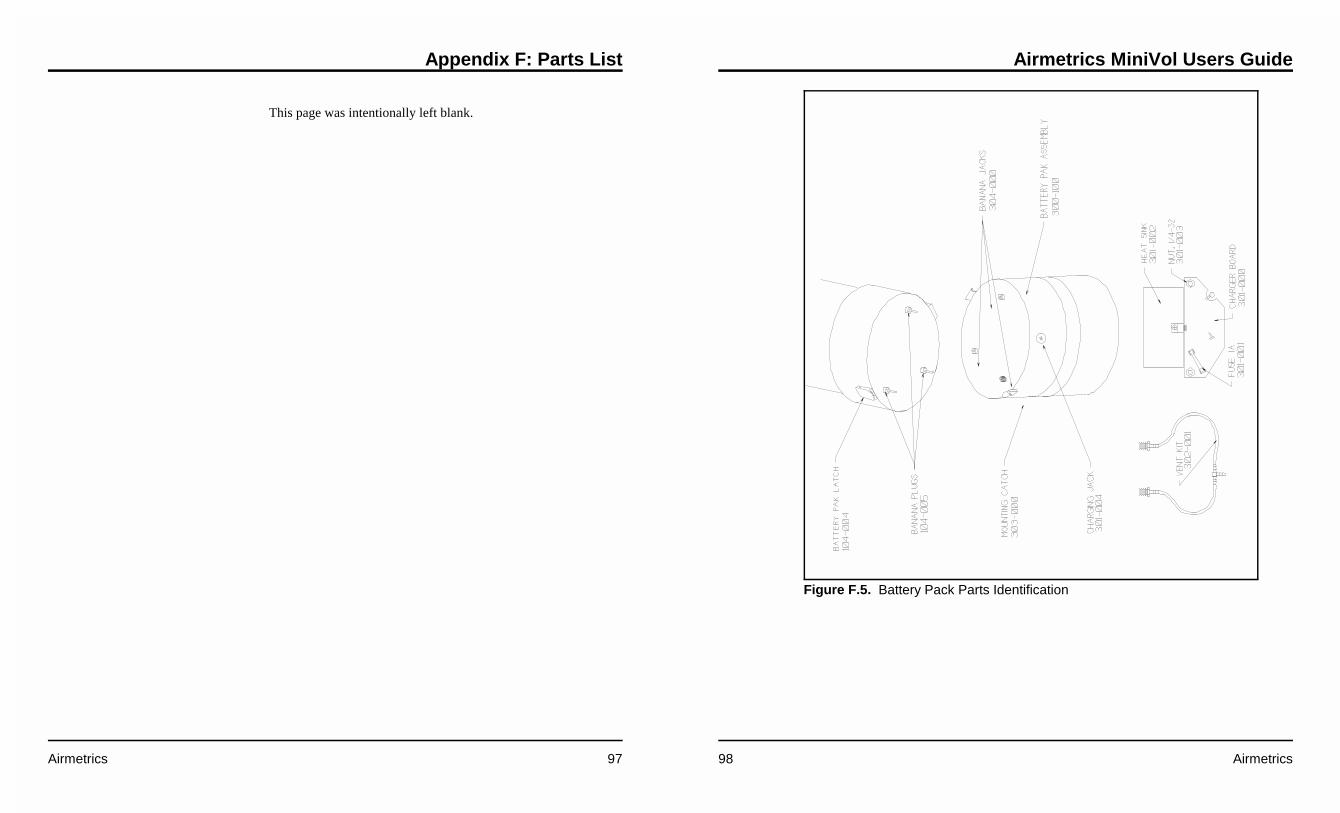
Appendix F: Parts List
Airmetrics 97
This page was intentionally left blank.
Airmetrics MiniVol Users Guide
98 Airmetrics
Figure F.5. Battery Pack Parts Identification

Appendix F: Parts List
Airmetrics 99
Battery Pack Assembly(see Figure F.5)
P/N Description
300-000 Battery Pack Assembly
301-000 Battery Charger Board
301-004 Charging Jack
302-000 Battery, 12V, 12AH
302-001 Vent Kit
303-000 Mounting Catch
304-000 Banana Jack
306-000 Transformer, 18 VAC
Airmetrics MiniVol Users Guide
100 Airmetrics
Figure F.6. Integrated Gas Sampling Bag Parts Identification

Appendix F: Parts List
Airmetrics 101
Integrated Gas Sampling Bag Assembly(see Figure F.6)
P/N Description
400-000 Complete Bag Module
400-001 Tedlar® Bag, 5 liter
400-003 Mini Quick-Connect Hose Fitting
400-004 Bag Sampling Bale Handle
400-005 Bale Bar, 24", PVC
400-006 Bale Bar, 16", PVC
400-010 Bag evacuation Fitting
Airmetrics MiniVol Users Guide
102 Airmetrics
Figure F.7. Mounting Hardware Parts Identification

Appendix F: Parts List
Airmetrics 103
Mounting Hardware(See Figure F.7)
P/N Description
501-000 Complete Telescoping Hoisting Pole Assembly
501-001 Telescoping Fiberglass Pole
501-002 Pole Hook
502-000 Mounting Cradle
503-000 Nylon Strap, 4 foot
504-000 Y-Bracket Assembly (Complete)
504-001 Cam Loop Strap
600-000 Tool Box, 9" × 9" × 18"
600-001 Operating Manual
Airmetrics MiniVol Users Guide
104 Airmetrics
Miscellaneous Parts
P/N Description

Appendix G: Forms and Schematics
Airmetrics 105
G FORMS and SCHEMATICS
The forms shown in this appendix are samples of the Field Data Sheets that may beused when performing PM sampling (Figure G.1) and Integrated Gas sampling(Figure G.2). Figures G.3, G.4 and G.5 are schematics for the electronic circuitry inthe MiniVol sampler.
Airmetrics MiniVol Users Guide
106 Airmetrics
This page was intentionally left blank.