minimizing of scour downstream hydraulic structures using sills
TRANSCRIPT

INTERNATIONAL JOURNAL OF CIVIL AND STRUCTURAL ENGINEERING
Volume 3, No 3, 2013
© Copyright by the authors - Licensee IPA- Under Creative Commons license 3.0
Research article ISSN 0976 – 4399
Received on February 2013 Published on March 2013 591
Minimizing of scour downstream hydraulic structures using sills Helal. E.Y1, Nassralla. T.H2, Abdelaziz. A.A3
1- Lecturer, Civil Eng. Dept., Minoufiya University, Egypt
2- Lecturer, Civil Eng. Dept., Benha University, Egypt
3- Demonstrator, Civil Eng. Dept., Benha University, Egypt
doi:10.6088/ijcser.201203013054
ABSTRACT
Scour is the consequence of the erosive action of flowing water, which removes and erodes
material from the bed and banks of streams and also from the vicinity of bridge piers and
abutments. Local scour downstream hydraulic structures may cause damage or complete
failure of these structures, so minimizing this phenomenon is very important. The study was
based on an experimental program included 144 tests. These tests were carried in a
rectangular flume with sills fixed in the Perspex floor of flume. Three cases of sill
arrangements were included, no sill, single line sill and fully silled floor. Different heights of
sill 2 cm, 4 cm and 6 cm, different positions at 0.4, 0.5, 0.6 and 0.7 of floor length were tested
under different flow conditions. The experiments showed that for most considered values of
sills heights and position, the value of Hd/Lf = 0.04 gave the smaller values of scour
parameters, while the value of Hd/Lf = 0.013 gave the higher values of scour parameters. Also,
it was noticed that for most considered values of sills height, the case of fully silled floor
gave the smaller values of scour parameters.
Keyword: Scour, sill, one row of sill, hydraulic structure, flume.
1. Introduction
Scour is the removal of boundary material by the action of flowing water, it occurs naturally
as a part of the morphological changes of rivers and man-made structures. Many researchers
studied scour downstream hydraulic structure. For example, M.A. Abourehim (1997) studied
the local scour phenomenon done downstream culvert outlets, particularly culvert with
triangular shape cross section, constructed on non uniform bed materials. The experimental
program included three main parts. The first part dealt with the effect of the discharge and tail
water depth on the scour hole geometry, formed downstream a culvert with triangular shape
cross section. The second part was concerned with the influence of the shape of culvert on
scour hole dimensions. Circular, square, rectangular, and triangular shapes, having the same
area, were tested. The third part was intended with determination of length of protection
required to safeguard the downstream bed material against local scour. Study showed that
scour hole geometry sensitively affected by culvert shape, discharge, and tail water depth.
Study showed also that length of scour hole was not the only criterion to determine the
required length of protection against local scour. Critical velocity might be used to estimate
the minimum length of protection.
Gamal abouzied (2006) studied the scour reach behind three vents regulator due to a drowned
and free hydraulic jump over a partially rigid apron extended to an erodible sand basin. The
study was performed in two categories; the first was to find out the sum of lengths of rigid
apron behind the gates in addition to the length of scour hole formed downstream while the

Minimizing of scour downstream hydraulic structures using sills
Helal. E.Y, Nassralla. T.H, Abdelaziz. A.A
International Journal of Civil and Structural Engineering 592
Volume 3 Issue 3 2013
second was to find the minimum length of rigid apron behind the gates to prevent erosion
downstream it. Both categories were carried out under the condition of symmetrical and
asymmetrical under-gated regulation, the mean diameter of the soil particles in the sand basin
was kept constant at 0.502 mm. He concluded that scour reach was found to be function in
the head difference between the upstream and downstream water levels (H) ,downstream tail
water depth (Y) the submergence of the under-gated regulation and the method of regulation
(symmetrical and asymmetrical). Asymmetrical under-gated regulation was not
recommended as a working regulation otherwise its effect had to be taken into consideration
during design process .Depth of scour hole formed behind an arbitrary length of floor depend
on bed shear stress due to flow motion and working head difference(H).
Abdel-Aal , et al. (2008) studied local scour mitigation around bridge piles using protective
plate. He investigated that, for all shapes of protective plates, the relative scour depth
decreased as the dimensions of the protective plate around the bridge pile increased. The
square protective plate was considered the best shape of collars for minimizing the scour hole
dimension around the pile. Moreover, the relative scour depth increased as the relative height
of collar over the mobile bed increased and vice versa. In which as the relative height of the
protective plate increased more downward flow acting was induced around the collar and
hence more scour hole was obtained in the upstream side.
R. Jafminia ,et al. (2010) used siphon spillway as a hydraulic structure which was in face of
scour problem. Used a physical model of siphon spillway, scour at the downstream of its
submerged jet was investigated. Experiments were conducted for four different discharges,
four different tail water elevations, three sizes of bed material and three different bucket
angles., the scour at downstream of its bucket was studied. Four effective parameters
(discharge of the siphon, tail water depth, bed material size and flip angle of bucket) on scour
hole size were considered and changed in various positions. Experiments showed that by
increasing the discharge, the scour hole was extended in length and depth. Increasing on tail
water depth had an inverse effect on scour geometry. In another sets of experiments, effect of
bed material sizes were investigated. To do this, three average sizes were used and results
showed that by increasing the bed material sizes, the scour hole was decreased. The angle of
takeoff was changed in these experiments (30°, 45° and 60°). The measured data indicated
that by increasing the flip angle of the bucket to vertical position, the length of scour hole was
decreased and the depth of scour hole was increased. Three empirical equations were
developed to predict the scour depth and its length.
2. Dimensional analysis
In the analysis of the problem of scour downstream hydraulic structure, the variables
considered were: H = the water head above the crest of weir, Y = tail water depth, Q =
water discharge through the flume, V = the mean velocity at the downstream cross section
of flume, g = gravitational acceleration, ρ = water density of the flow, µ = dynamic
viscosity of the water d50 = mean particle diameter, ρs = soil particle density, Lap = length
of apron, Hd = sill height, Lf = floor length, L = distance from the weir toe to sill line , So =
bed slope of the flume, B = width of flume, t= thickness of sill, Ds = maximum scour
depth,(see Figure 1).The functional relationship for the maximum scour depth Ds, could be
expressed as follow
Minimizing of scour downstream hydraulic structures using sills
Helal. E.Y, Nassralla. T.H, Abdelaziz. A.A
International Journal of Civil and Structural Engineering 593
Volume 3 Issue 3 2013
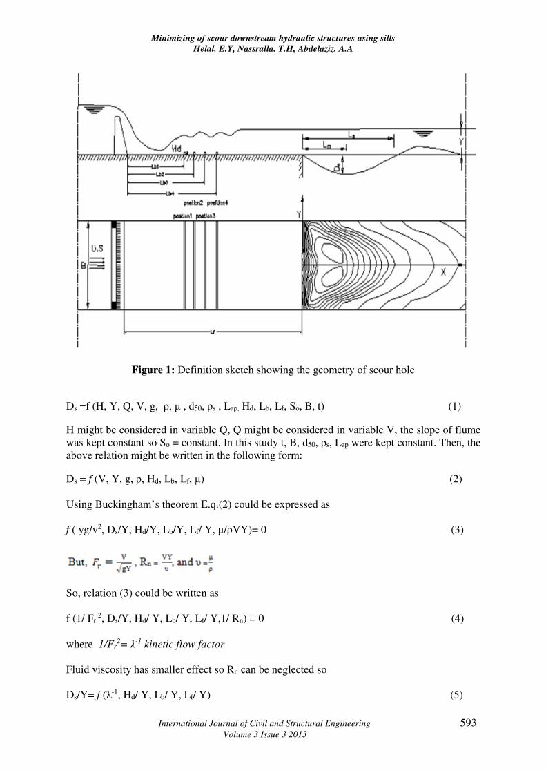
Figure 1: Definition sketch showing the geometry of scour hole
Ds =f (H, Y, Q, V, g, ρ, µ , d50, ρs , Lap, Hd, Lb, Lf, So, B, t) (1)
H might be considered in variable Q, Q might be considered in variable V, the slope of flume
was kept constant so So = constant. In this study t, B, d50, ρs, Lap were kept constant. Then, the
above relation might be written in the following form:
Ds = f (V, Y, g, ρ, Hd, Lb, Lf, µ) (2)
Using Buckingham’s theorem E.q.(2) could be expressed as
f ( yg/v2, Ds/Y, Hd/Y, Lb/Y, Lf/ Y, µ/ρVY)= 0 (3)
So, relation (3) could be written as
f (1/ Fr 2, Ds/Y, Hd/ Y, Lb/ Y, Lf/ Y,1/ Rn) = 0 (4)
where 1/Fr2= λ-1 kinetic flow factor
Fluid viscosity has smaller effect so Rn can be neglected so
Ds/Y= f (λ-1, Hd/ Y, Lb/ Y, Lf/ Y) (5)

Minimizing of scour downstream hydraulic structures using sills
Helal. E.Y, Nassralla. T.H, Abdelaziz. A.A
International Journal of Civil and Structural Engineering 594
Volume 3 Issue 3 2013
Similarly to relation (5) it can be concluded that:
Ls/Y= f (λ-1, Hd/ Y, Lb/ Y, Lf/ Y) (6)
3. Materials and methods
The experimental equipment included flume, tail gate, measuring carriage and devices for
measuring the discharge and water surface level.
3.1 The flume
It was rectangular recirculating flume with 14 m length, 0.6 m width, and 0.6 m height. The
flume was made from plexiglass fixed to a steel frame as shown in photo (1), the inlet part of
the flume consisted of elevated tank with dimensions (1.72 m length x 0.92 m width x 1.6 m
height). The head tank was connected by the channel through a vertical sluice gate. The
operating system was re-circulated through underground reservoir with 2m width, 3m length
and 2m height which was constructed to supply the flume with water. Centrifugal pump driven
by induction motor to re-circulated the flow from an underground reservoir to the flume. To
control the water flow rate, a gate valve was installed on the pipe line at delivery side of the
pump. The return channel passed water from the main channel to the underground reservoir.
The return channel was built up from brick. The depth of water in the flume was adjusted by
tail gate provided at the downstream end of the flume. Water depths and bed levels were
measured by a point-gauge ( Abdelaziz , et al.,2012).
3.2 The experimental models
The model was a Fayoum type weir made of wood was used as a heading-up structure. The
weir had 5 cm crest width, 50 cm crest length, 17 cm height, slope of 1:2 and two side
contraction wing walls each of 5 cm width, the weir was followed by a solid floor of length
1.5 m, and 0.60 m width and made of Perspex to avoid the deformations under the action of
water ( Abdelaziz , et al.,2012) , the sills was fitted in floor body, the experimental tests were
categorized in three sets as follow. 1- The first set of the experiments was carried out without
sill. 2- The second set of the experiments was carried out using one sill. It included four
positions of sill where Lb/Lf = 0.4, 0.5, 0.6, and 0.7. For each position of sill, four relative
heights of sill, Hd/Lf=1.33, 1.0, 0.66, and 0.33 were used(see photo2). 3- The third set of the
experiments was carried out using fully silled floor had the same height of sill as mentioned
for the second set. For each set, three values of discharge were used, for each value of
discharge; three values of downstream water depth were used.
3.3 The experimental procedures
After the flume was filled with bed material (sand) and accurately leveled, the leveling
accuracy was checked by means of a point gauge. The following steps were carried out for
each test:1- The sill was fitted with certain height and position, 2- The tail gate was completely
closed, back water feeding was started first until its depth reached higher than the desired
downstream water depth, 3- The control valve at the feeding opening was gradually opened till
the required discharge was maintained, 4- The exact water discharge was measured using the
sharp crested weir, 5- The tail gate was screwed gradually until the required downstream water
depth was arrived using the point gauge, 6- The time of the test was started, 7- After 2 hours
(where there is no appreciable change in scour hole profile), the pump was switched off, 8-

Minimizing of scour downstream hydraulic structures using sills
Helal. E.Y, Nassralla. T.H, Abdelaziz. A.A
International Journal of Civil and Structural Engineering 595
Volume 3 Issue 3 2013
The flume was emptied from water by tail gate very slowly in order not to disturb the scour
hole obtained, 9- After the scour hole was drained, the maximum scour depth, length were
recorded using point gauge at centerline of flume as the scour hole was symmetry( Abdelaziz ,
et al.,2012).
Photo 1: The flume (Abdelaziz , et al.,2012)
Photo 2: Case of single line of sill (Abdelaziz, A.A., et al 2012)

Minimizing of scour downstream hydraulic structures using sills
Helal. E.Y, Nassralla. T.H, Abdelaziz. A.A
International Journal of Civil and Structural Engineering 596
Volume 3 Issue 3 2013
4. Results and discussion
4.1 The effect of λ-1 on Ds/Y
Figure (2) Shows variation of Ds/Y with λ-1. It's found that for all considered heights and
positions either case of single line of sill or fully silled floor , increasing of λ-1 leads to
decrease in Ds/Y. This means that, increasing of Froude number leads to increase in Ds/Y.
For all considered values of position, the value of Hd/Lf = 0.04 gives the smaller values of
Ds/Y. except Lb/Lf =0.5 for λ-1 < 8.1 and fully silled floor for λ-1 < 7.5 the value of Hd/Lf =
0.026 gives the smaller values of Ds/Y.
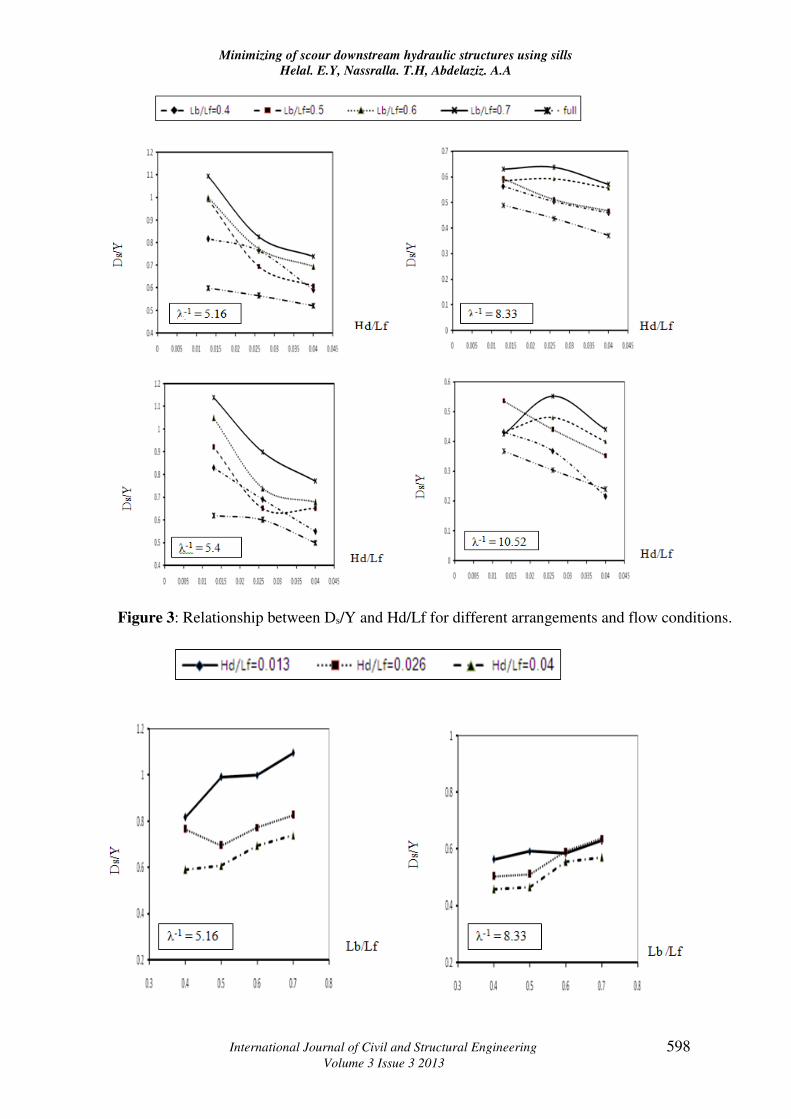
4.2 The effect of Hd/Lf on Ds/Y
Figure (3) Shows variation of Ds/Y with Hd/Lf. It's found that for all considered heights and
positions either case of single line of sill or fully silled floor, increasing Hd/Lf has no trend
with Ds/Y.
4.3 The effect of Lb/Lf on Ds/Y
Figure (4) Shows variation of Ds/Y with Lb/Lf. It's found that for all considered heights and
positions either case of single line of sill or fully silled floor, the value of Hd/Lf = 0.04 gives
the smaller values of Ds/Y.
4.4 The effect of λ-1 on Ls/Y
Figure (5) Shows variation of Ls/Y with λ-1. It's found that for all considered heights and
positions either case of single line of sill or fully silled floor, increasing of λ-1 leads to decrease
in Ls/Y. This means that, increasing of Froude number leads to increase in Ls/Y.
For all considered values of position, the value of Hd/Lf = 0.04 gives the smaller values of
Ds/Y. except fully silled floor for λ-1 < 7.5 the value of Hd/Lf = 0.026 gives the smaller values
of Ls/Y.
4.5 The effect of Hd/Lf on Ls/Y
Figure (6) Shows variation of Ls/Y with Hd/Lf. It's found that for all considered heights and
positions either case of single line of sill or fully silled floor, the value of fully silled floor
gives the smaller values of Ls/Y except λ-1 = 8.33 and Hd/Lf > 0.03, the value of Lb/Lf =0.4
give the smaller values of Ls/Y.
4.6 The effect of Lb/Lf on Ls/Y
Figure (7) Shows variation of Ls/Y with Lb/Lf. It's found that for all considered heights and
positions either case of single line of sill or fully silled floor, the value of Hd/Lf = 0.04 gives
the smaller values of Ls/Y, while the value of Hd/Lf = 0.013 gives the higher values of Ls/Y for
most considered heights and position.

Minimizing of scour downstream hydraulic structures using sills
Helal. E.Y, Nassralla. T.H, Abdelaziz. A.A
International Journal of Civil and Structural Engineering 597
Volume 3 Issue 3 2013
Figure 2: Relationship between Ds/Y and λ-1 for different arrangements and sill heights.
Minimizing of scour downstream hydraulic structures using sills
Helal. E.Y, Nassralla. T.H, Abdelaziz. A.A
International Journal of Civil and Structural Engineering 598
Volume 3 Issue 3 2013
Figure 3: Relationship between Ds/Y and Hd/Lf for different arrangements and flow conditions.

Minimizing of scour downstream hydraulic structures using sills
Helal. E.Y, Nassralla. T.H, Abdelaziz. A.A
International Journal of Civil and Structural Engineering 599
Volume 3 Issue 3 2013
Figure 4 : Relationship between Ds/Y and Lb/Lf for different sill heights and flow conditions
Figure 5: Relationship between Ls/Y and λ-1 for different arrangements and sill heights.

Minimizing of scour downstream hydraulic structures using sills
Helal. E.Y, Nassralla. T.H, Abdelaziz. A.A
International Journal of Civil and Structural Engineering 600
Volume 3 Issue 3 2013
Figure.6: Relationship between Ls/Y and Hd/Lf for different arrangements and flow
conditions

Minimizing of scour downstream hydraulic structures using sills
Helal. E.Y, Nassralla. T.H, Abdelaziz. A.A
International Journal of Civil and Structural Engineering 601
Volume 3 Issue 3 2013
Figure 7: Relationship between Ls/Y and Lb/Lf for different sill heights and flow conditions
5. Conclusion
For two cases of single line of sill and fully silled, increasing of kinetic flow factor (λ-1) leads
to decrease in the maximum scour depth for all considered opening arrangements. Most
considered values of sills heights and position, the value of Hd/Lf = 0.04 gives the smaller
values of scour parameters, while the value of Hd/Lf = 0.013 gives the higher values of scour
parameters. Also, it was noticed that for most considered values of sills height, the case of
fully silled floor gave the smaller values of scour parameters
6. References
1. Abdel-Aal, G.M, Mohamed, Y.A, Waheed E-Din, O. and El-folly, M., (2008), Local
scour mitigation around bridge piles using protective plate (collar), Scientific bulletin.
Faculty of engineering. Ain Shames University. Faculty of engineering. Cairo. Egypt.

Minimizing of scour downstream hydraulic structures using sills
Helal. E.Y, Nassralla. T.H, Abdelaziz. A.A
International Journal of Civil and Structural Engineering 602
Volume 3 Issue 3 2013
2. Abdelaziz, A.A., (2011), Minimizing of scour downstream hydraulic structures, M.Sc.
Thesis, Civil Dep., Benha University
3. Abdelaziz, A.A.(2012), Scour depth downstream weir with opening, International
journal of civil and structural engineering, 3(1), pp 259-270.
4. El-Azab, E.E.D.Y., (2003), Minimizing of scour downstream hydraulic structure using
straight deflector baffles, M.Sc. thesis, Civil Dep., Minufiya University.
5. Gamal abouzied A.Rahim., (2006), Estimation of minimum floor length behind sulice
gates against scour utilizing solid bed and erodible basin Jour. of Assuit University,
34(3).
6. M.A Abourehim., (1997), Local scour downstream culvert outlets Jour. of Alexandria
University, 36(1).
7. May, R.W.P., Ackers, J. C., Kirby, A.M., (2002), Manual on scour at bridges and other
hydraulic structures, CIRIA, pp 25-30.
8. Nassralla, T. H., (2008), Hydraulic characteristics of flow in open channels with
emergent weeds, Ph.D. Thesis, Civil Dep., Minoufiya University.