miniature active damping stage for scanning probe ... · review of scientific instruments 83,...
TRANSCRIPT

Miniature active damping stage for scanning probe applications in ultrahigh vacuumMaximilian Assig, Andreas Koch, Wolfgang Stiepany, Carola Straßer, Alexandra Ast et al. Citation: Rev. Sci. Instrum. 83, 033701 (2012); doi: 10.1063/1.3689769 View online: http://dx.doi.org/10.1063/1.3689769 View Table of Contents: http://rsi.aip.org/resource/1/RSINAK/v83/i3 Published by the American Institute of Physics. Related Articles18/20 T high magnetic field scanning tunneling microscope with fully low voltage operability, high currentresolution, and large scale searching ability Rev. Sci. Instrum. 83, 043706 (2012) Ultra compact multitip scanning tunneling microscope with a diameter of 50 mm Rev. Sci. Instrum. 83, 033707 (2012) A nanopositioner for scanning probe microscopy: The KoalaDrive Rev. Sci. Instrum. 83, 023703 (2012) Rapid measurement of a high step microstructure with 90° steep sidewall Rev. Sci. Instrum. 83, 013706 (2012) Insulated gold scanning tunneling microscopy probes for recognition tunneling in an aqueous environment Rev. Sci. Instrum. 83, 015102 (2012) Additional information on Rev. Sci. Instrum.Journal Homepage: http://rsi.aip.org Journal Information: http://rsi.aip.org/about/about_the_journal Top downloads: http://rsi.aip.org/features/most_downloaded Information for Authors: http://rsi.aip.org/authors
Downloaded 18 Apr 2012 to 134.105.184.12. Redistribution subject to AIP license or copyright; see http://rsi.aip.org/about/rights_and_permissions

REVIEW OF SCIENTIFIC INSTRUMENTS 83, 033701 (2012)
Miniature active damping stage for scanning probe applicationsin ultra high vacuum
Maximilian Assig,1,a) Andreas Koch,1 Wolfgang Stiepany,1 Carola Straßer,1
Alexandra Ast,2 Klaus Kern,1,3 and Christian R. Ast11Max-Planck-Institut für Festkörperforschung, 70569 Stuttgart, Germany2Institut für Technische und Numerische Mechanik, Universität Stuttgart, 70569 Stuttgart, Germany3Institut de Physique de la Matière Condensée, Ecole Polytechnique Fédérale de Lausanne,1015 Lausanne, Switzerland
(Received 25 August 2011; accepted 8 February 2012; published online 2 March 2012)
Scanning probe microscope (SPM) experiments demand a low vibration level to minimize theexternal influence on the measured signal. We present a miniature six-degree of freedom activedamping stage based on a Gough-Stewart platform (hexapod) which is positioned in ultra highvacuum as close to the SPM as possible. In this way, vibrations originating from the experimentalsetup can be effectively reduced providing a quiet environment for the SPM. In addition, the hexapodprovides a rigid reference point, which facilitates wiring as well as sample transfer. We outline themain working principle and show that for scanning tunneling microscopy (STM) measurements of aSi(111) 7 × 7 surface, the hexapod significantly improves the stability and quality of the topographicimages. © 2012 American Institute of Physics. [http://dx.doi.org/10.1063/1.3689769]
I. INTRODUCTION
Scanning probe microscopes (SPMs) are experimentaltools to investigate local physical phenomena on surfaces.1, 2
The observed measurement signal is extremely sensitive tovariations in the distance between tip and sample. Alreadysmall mechanical vibrations of the SPM can have very largeinfluences on the measured signal. For measurements withgood resolution a variation in the distance between tip andsample of less than a picometer is desirable. This can be doneby design considerations to reduce the response of the tip-sample distance to external vibrations,3 but in general it is ad-vantageous to have a low vibration level to begin with. Decou-pling the whole experimental chamber from the lab environ-ment is accomplished by a combined use of a set of externalactive and/or passive damping stages. However, these damp-ing stages are usually ineffective against vibrations originat-ing from the setup, e. g., vibrations from boiling cryoliquidsor cooling stages (e. g., 1 K-pot). Therefore, it is desirable toinclude additional damping stages as close as possible to theactual SPM measurement head.
A standard technique to introduce sufficient dampingclose to the SPM is the use of eddy current damping.4–6 Sincethe forces generated by the eddy currents are comparativelysmall and in order to keep a low resonance frequency, theSPM has to be weakly attached by soft springs to the sur-rounding structure, so that the damping can be effective. Asa result, additional mechanisms have to be included into thesystem in order to restrain it, when the SPM has to be accessedfrom the outside, e. g., for sample transfer or maintenance.Furthermore, because the eddy currents are induced by mag-netic fields, the approach is not applicable, if strong magneticfields are part of the experimental setup itself. An alternative
a)Author to whom correspondence should be addressed. Electronic mail:[email protected].
approach, which overcomes these drawbacks, is to decouplethe SPM from the surrounding by the use of an active me-chanical system with a stiff connection to the experimentalchamber.
Here, we describe the use of an active mechanical damp-ing system for a scanning tunneling microscope (STM) tooperate in ultra high vacuum. We have adapted the con-cept of the Gough-Stewart platform or hexapod7–9 to be in-corporated between the STM and the surrounding structureof the experimental chamber. A hexapod is a special kindof parallel kinematic machine,10 which consists of a baseplate and a payload plate connected by six legs or strutswith variable length. It enables the control of all six degreesof freedom in space (three translations and three rotations).Hexapods are widely used as positioning devices, e.g., forflight simulators.9, 11 Their usefulness as machine tools is atopic of ongoing research.12, 13 Since the beginning of the1990s, the capabilities of hexapods for the purpose of vibra-tion isolation are investigated.14 Preumont et al.15–17 furtherdeveloped these control strategies showing that it is possibleto damp prominent resonances in truss structures over a broadfrequency spectrum while keeping the ability to control theposition of the attached device.
Following the results of Preumont et al., we designed aminiature hexapod and combined it with a decentralized ac-tive damping strategy featuring local controllers for each strutof the hexapod. It decouples the STM from the rest of thestructure and can achieve a sufficiently high damping over abroad frequency spectrum. Furthermore, a robust stability ofthe system is guaranteed by the chosen control algorithm. Inthe following, the key features of the hexapod setup and thecontrol algorithm will be explained. Measurements of the sen-sor signal from the hexapod struts as well as of the tunnelingcurrent with the STM feedback loop deactivated show the ef-fectiveness of the chosen damping approach. Finally, imagesof a Si(111) 7 × 7 surface demonstrate the increase in stability
0034-6748/2012/83(3)/033701/6/$30.00 © 2012 American Institute of Physics83, 033701-1
Downloaded 18 Apr 2012 to 134.105.184.12. Redistribution subject to AIP license or copyright; see http://rsi.aip.org/about/rights_and_permissions
033701-2 Assig et al. Rev. Sci. Instrum. 83, 033701 (2012)
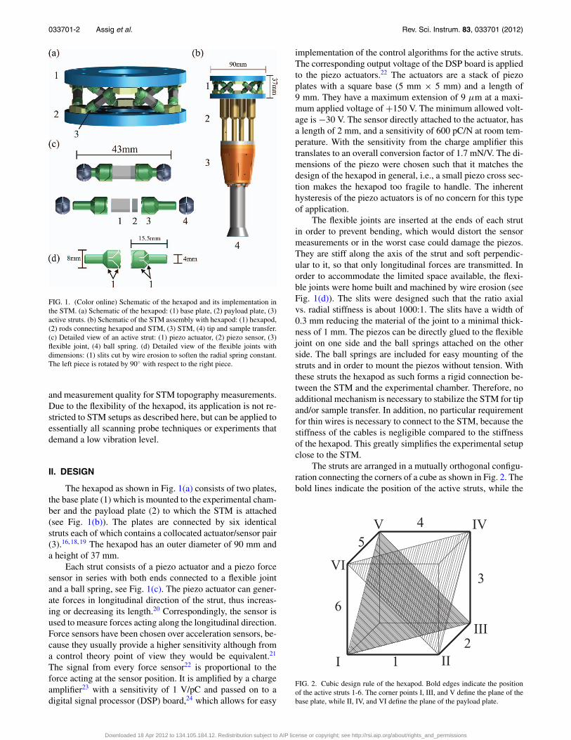
FIG. 1. (Color online) Schematic of the hexapod and its implementation inthe STM. (a) Schematic of the hexapod: (1) base plate, (2) payload plate, (3)active struts. (b) Schematic of the STM assembly with hexapod: (1) hexapod,(2) rods connecting hexapod and STM, (3) STM, (4) tip and sample transfer.(c) Detailed view of an active strut: (1) piezo actuator, (2) piezo sensor, (3)flexible joint, (4) ball spring. (d) Detailed view of the flexible joints withdimensions: (1) slits cut by wire erosion to soften the radial spring constant.The left piece is rotated by 90◦ with respect to the right piece.
and measurement quality for STM topography measurements.Due to the flexibility of the hexapod, its application is not re-stricted to STM setups as described here, but can be applied toessentially all scanning probe techniques or experiments thatdemand a low vibration level.
II. DESIGN
The hexapod as shown in Fig. 1(a) consists of two plates,the base plate (1) which is mounted to the experimental cham-ber and the payload plate (2) to which the STM is attached(see Fig. 1(b)). The plates are connected by six identicalstruts each of which contains a collocated actuator/sensor pair(3).16, 18, 19 The hexapod has an outer diameter of 90 mm anda height of 37 mm.
Each strut consists of a piezo actuator and a piezo forcesensor in series with both ends connected to a flexible jointand a ball spring, see Fig. 1(c). The piezo actuator can gener-ate forces in longitudinal direction of the strut, thus increas-ing or decreasing its length.20 Correspondingly, the sensor isused to measure forces acting along the longitudinal direction.Force sensors have been chosen over acceleration sensors, be-cause they usually provide a higher sensitivity although froma control theory point of view they would be equivalent.21
The signal from every force sensor22 is proportional to theforce acting at the sensor position. It is amplified by a chargeamplifier23 with a sensitivity of 1 V/pC and passed on to adigital signal processor (DSP) board,24 which allows for easy
implementation of the control algorithms for the active struts.The corresponding output voltage of the DSP board is appliedto the piezo actuators.22 The actuators are a stack of piezoplates with a square base (5 mm × 5 mm) and a length of9 mm. They have a maximum extension of 9 μm at a maxi-mum applied voltage of +150 V. The minimum allowed volt-age is −30 V. The sensor directly attached to the actuator, hasa length of 2 mm, and a sensitivity of 600 pC/N at room tem-perature. With the sensitivity from the charge amplifier thistranslates to an overall conversion factor of 1.7 mN/V. The di-mensions of the piezo were chosen such that it matches thedesign of the hexapod in general, i.e., a small piezo cross sec-tion makes the hexapod too fragile to handle. The inherenthysteresis of the piezo actuators is of no concern for this typeof application.
The flexible joints are inserted at the ends of each strutin order to prevent bending, which would distort the sensormeasurements or in the worst case could damage the piezos.They are stiff along the axis of the strut and soft perpendic-ular to it, so that only longitudinal forces are transmitted. Inorder to accommodate the limited space available, the flexi-ble joints were home built and machined by wire erosion (seeFig. 1(d)). The slits were designed such that the ratio axialvs. radial stiffness is about 1000:1. The slits have a width of0.3 mm reducing the material of the joint to a minimal thick-ness of 1 mm. The piezos can be directly glued to the flexiblejoint on one side and the ball springs attached on the otherside. The ball springs are included for easy mounting of thestruts and in order to mount the piezos without tension. Withthese struts the hexapod as such forms a rigid connection be-tween the STM and the experimental chamber. Therefore, noadditional mechanism is necessary to stabilize the STM for tipand/or sample transfer. In addition, no particular requirementfor thin wires is necessary to connect to the STM, because thestiffness of the cables is negligible compared to the stiffnessof the hexapod. This greatly simplifies the experimental setupclose to the STM.
The struts are arranged in a mutually orthogonal configu-ration connecting the corners of a cube as shown in Fig. 2. Thebold lines indicate the position of the active struts, while the
I II
V
VI
III
IV
12
3
4
5
6
FIG. 2. Cubic design rule of the hexapod. Bold edges indicate the positionof the active struts 1-6. The corner points I, III, and V define the plane of thebase plate, while II, IV, and VI define the plane of the payload plate.
Downloaded 18 Apr 2012 to 134.105.184.12. Redistribution subject to AIP license or copyright; see http://rsi.aip.org/about/rights_and_permissions

033701-3 Assig et al. Rev. Sci. Instrum. 83, 033701 (2012)
66
55
44
33
22
11
Mea
sure
d S
enso
r
6
6
5
5
4
4
3
3
2
2
1
1
Excited Sensor
100
80
60
40
20
0
Cross coupling (%
)
FIG. 3. Measurement of the cross coupling between the active struts. Sym-bols in the matrix fields indicating parallel (‖) or perpendicular (⊥) struts.Results have been normalized with respect to the sensor signal of the excitedstrut.
triangular areas depict the base (nodes I, III, V) and payloadplate (nodes II, IV, VI). This architecture is chosen, becauseit provides uniform control capabilities as well as a uniformstiffness in all directions. Furthermore, it minimizes the cross-coupling between actuators. Figure 3 shows a measurement ofthe remaining cross coupling between the struts. Each actua-tor is successively excited with a sine signal, while the re-sulting sensor signal in each strut is observed. The controllersare switched off during these measurements. The horizontaland vertical axes in Fig. 3 correspond to the excited and mea-sured struts, respectively. The matrix fields show the normal-ized magnitude of the measured response, i.e., the diagonalelements are correspondingly equal to one. The inset in eachmatrix field indicates the relative orientation of the respectivestruts. As is to be expected, the smallest cross coupling, whichis around 15%, can be observed between the struts perpendic-ular to each other. For the parallel struts the cross couplingis around 30%. In general, the cross coupling remains on atolerable level for the control algorithm described in Sec. III.
III. CONTROL ALGORITHM
Because the struts of the hexapods are only weakly cou-pled among each other and the acutator/sensor pairs are collo-cated, a decentralized control algorithm acting independentlyon each active strut can be chosen. Control algorithms basedon collocation are most frequently used for active damping,since they guarantee closed-loop stability. In addition, theyare usually easy to implement and tune.21, 25 For the controlof the active struts of the hexapod, an integrated force feed-back (IFF) is implemented, since the forces acting in the strutsare readily available with the force sensors. Generally, controlalgorithms based on force sensors are more robust than ac-celeration sensors.21 This control concept is well suited fordamping the resonances in the system up to the frequencyrange where the piezos themselves become resonant. The ba-sic principle of the IFF is to generate the actuator output signalu directly from the time integral of the axial force F acting onthe piezo
u = −g∫
Fdt, (1)
where g is the control gain. The IFF aims at increasing thedamping in the system. As the damping in a mechanical sys-tem is proportional to the velocity, the force signal, which isproportional to acceleration, is integrated. For the digital im-plementation with the sample time T, the control algorithm istransformed into the corresponding difference equation usinga bilinear or Tustin transformation:
ui+1 = αui − gT
2(Fi+1 + Fi ), (2)
where i denotes the ith time step. The forgetting factor α
is introduced to prevent saturation of the integral controlalgorithm.21 It has to be chosen slightly smaller than one,so that no saturation occurs but the performance of the con-troller is not affected. More details on the control algorithmand the underlying principles of active damping can be foundin Ref. 21.
Since the design of the hexapod is symmetric and orthog-onal, equal values of g and α can be chosen for all struts, re-sulting in a uniform behavior, when the controller is switchedon or off. The control algorithm is implemented as a Simulinkmodel in MATLAB26 independently for each active strut andtransferred to the memory of the DSP board. The tuning of α
and g is done heuristically starting with a low value for thecontrol gain g and a value of α very close or equal to one.The value of g is then increased until the stability limit ofthe controller is reached. Unconditional stability can only beguaranteed with IFF for ideal systems without a finite sam-pling time, no input/output delays, crosstalk, etc. For real sys-tems, the control loop will eventually become unstable, if g ischosen just high enough. Then the forgetting factor α can beadjusted, so that the system becomes stable again. However, ifα is chosen too small, the control algorithm will loose its in-tegral behavior and the performance of the controlled systemwill degrade significantly. Thus, if no further improvement inthe system behavior can be achieved by adjusting g and α, theoptimal values are found.
IV. RESULTS AND DISCUSSION
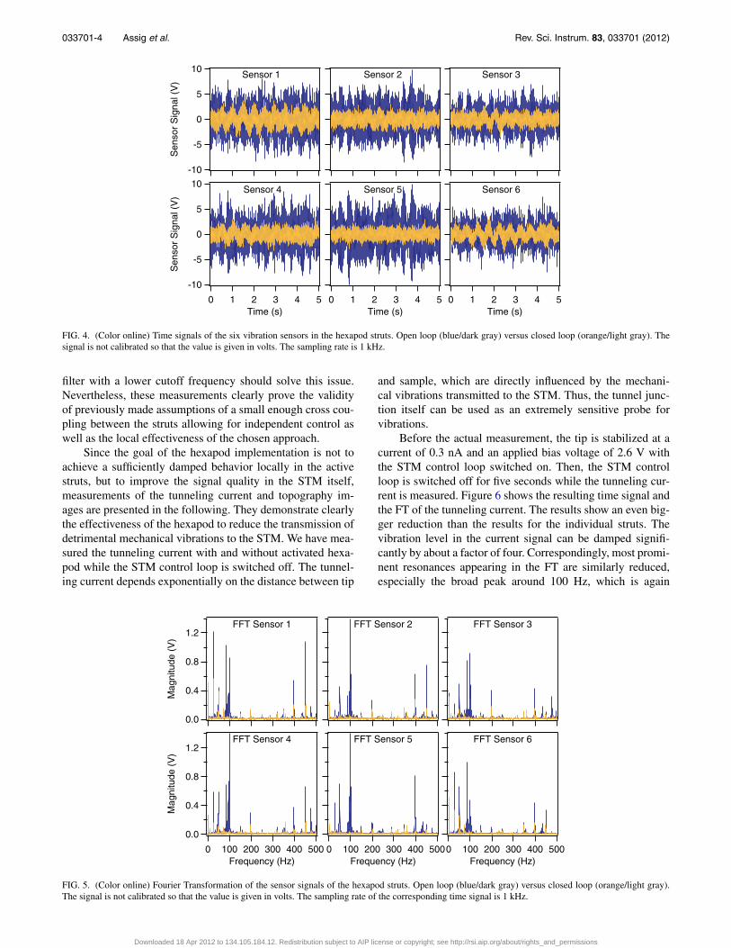
A first test of the damping performance of the hexapodcan be made by comparing the sensor outputs of the six activestruts for the open loop and the closed loop case, see Fig. 4.The amplitude of time signal for the open loop case (blue/darkgray curve) is approximately twice as large as for system withactivated control (orange/light gray curve). This behavior canbe observed in all six sensor signals. The voltages applied tothe actuator is commonly on the order of 1 V or less, which isless than 1% of the maximum allowed voltage. The advantagehere is that the heat generation through the hexapod is quitelow, which may become an important aspect in low temper-ature applications. The Fourier transformations (FT) of thetime signals in Fig. 5 show a similar reduction of at least afactor of two for most resonance peaks. Prominent resonancesat about 100 Hz are even completely suppressed. A low fre-quency vibration at around 2 Hz can still be observed in theclosed loop data. This frequency is cut off by a 3 Hz highpass filter in the charge amplifier, so that the controller can-not effectively reduce such low lying vibrations. A high pass
Downloaded 18 Apr 2012 to 134.105.184.12. Redistribution subject to AIP license or copyright; see http://rsi.aip.org/about/rights_and_permissions
033701-4 Assig et al. Rev. Sci. Instrum. 83, 033701 (2012)
543210Time (s)
Sensor 5
543210Time (s)
Sensor 6
-10
-5
0
5
10S
enso
r S
igna
l (V
)
543210Time (s)
Sensor 4
Sensor 3 Sensor 2
-10
-5
0
5
10
Sen
sor
Sig
nal (
V)
Sensor 1
FIG. 4. (Color online) Time signals of the six vibration sensors in the hexapod struts. Open loop (blue/dark gray) versus closed loop (orange/light gray). Thesignal is not calibrated so that the value is given in volts. The sampling rate is 1 kHz.
filter with a lower cutoff frequency should solve this issue.Nevertheless, these measurements clearly prove the validityof previously made assumptions of a small enough cross cou-pling between the struts allowing for independent control aswell as the local effectiveness of the chosen approach.
Since the goal of the hexapod implementation is not toachieve a sufficiently damped behavior locally in the activestruts, but to improve the signal quality in the STM itself,measurements of the tunneling current and topography im-ages are presented in the following. They demonstrate clearlythe effectiveness of the hexapod to reduce the transmission ofdetrimental mechanical vibrations to the STM. We have mea-sured the tunneling current with and without activated hexa-pod while the STM control loop is switched off. The tunnel-ing current depends exponentially on the distance between tip
and sample, which are directly influenced by the mechani-cal vibrations transmitted to the STM. Thus, the tunnel junc-tion itself can be used as an extremely sensitive probe forvibrations.
Before the actual measurement, the tip is stabilized at acurrent of 0.3 nA and an applied bias voltage of 2.6 V withthe STM control loop switched on. Then, the STM controlloop is switched off for five seconds while the tunneling cur-rent is measured. Figure 6 shows the resulting time signal andthe FT of the tunneling current. The results show an even big-ger reduction than the results for the individual struts. Thevibration level in the current signal can be damped signifi-cantly by about a factor of four. Correspondingly, most promi-nent resonances appearing in the FT are similarly reduced,especially the broad peak around 100 Hz, which is again
1.2
0.8
0.4
0.0
Mag
nitu
de (
V)
5004003002001000Frequency (Hz)
FFT Sensor 4
5004003002001000Frequency (Hz)
FFT Sensor 5
5004003002001000Frequency (Hz)
FFT Sensor 6
FFT Sensor 3FFT Sensor 21.2
0.8
0.4
0.0
Mag
nitu
de (
V)
FFT Sensor 1
FIG. 5. (Color online) Fourier Transformation of the sensor signals of the hexapod struts. Open loop (blue/dark gray) versus closed loop (orange/light gray).The signal is not calibrated so that the value is given in volts. The sampling rate of the corresponding time signal is 1 kHz.
Downloaded 18 Apr 2012 to 134.105.184.12. Redistribution subject to AIP license or copyright; see http://rsi.aip.org/about/rights_and_permissions

033701-5 Assig et al. Rev. Sci. Instrum. 83, 033701 (2012)
2.0
1.5
1.0
0.5
0.0
Mag
nitu
de (
pA)
5004003002001000Frequency (Hz)
-40
-20
0
20
40C
urre
nt (
pA)
543210 Time (s)
FIG. 6. (Color online) Tunneling current with deactivated feedback loop ofthe STM controller measured on a Si(111) 7 × 7 surface: (a) Time signal ofthe tunneling current and (b) the FT of the time signal. Open loop (blue/darkgray) versus closed loop (orange/light gray). The sampling rate is 10 kHz.
completely suppressed. The low frequency vibration around2 Hz can again be related to the high pass filter in the chargeamplifier (see above). These measurements clearly show thatthe local damping achieved by each individual strut in com-bination with the cubic design of the hexapod is capable todecouple the STM from most of the transmitted mechanicalvibrations from the inside of the experimental chamber.
To finally show that the reduction of the transmitted me-chanical vibrations close to the STM has a direct effect on themeasurement quality and stability, Fig. 7 shows two topogra-phy measurements of a Si(111) 7 × 7 surface. The measure-ments were taken in constant current mode with an appliedbias voltage of 1.0 V and a current set point of 0.8 nA at roomtemperature. The topography in Fig. 7(a) taken with the hexa-pod controller switched off shows an enhanced noise level.The noise level is absent in Fig. 7(b), which was taken with
9.1Å9.1Å
(a) (b)1.3 Å
0.0 Å
FIG. 7. Scanning tunneling microscopy image of a Si(111) 7 × 7 surface:(a) Topography image taken with deactivated hexapod (b) Image of the samescanning area (slightly shifted by thermal drift) with hexapod activated.
activated hexapod control. Thus, including the active damp-ing stage close to the STM leads to a significantly improvedmeasurement quality.
V. CONCLUSION
In conclusion, we have presented a novel approach forSTMs to greatly reduce the transmission of mechanical vi-brations to the sensitive measurement tip. It consists of aUHV compatible miniature hexapod as an additional activedamping stage implemented as close as possible to the ac-tual STM. Due to the orthogonal design, it can be controlledwith a decentralized integrated force feedback algorithm, aswas already shown by Preumont et al.21 The resulting sys-tem is able to reduce the mechanical vibrations transmittedto the STM tip by at least a factor of two over a broad fre-quency spectrum. Correspondingly, the presented topographyimages of a Si(111) 7 × 7 surface show a clear reduction ofthe noise level, when the hexapod is activated. Furthermore,the hexapod simplifies the design of the experimental setup ingeneral as no particular requirement for thin wires is imposednor a special stabilization mechanism is needed for tip/sampletransfer. Even though we tested the hexapod only in UHV andat room temperature, from design considerations we projectthat it can also operate at low temperatures and high magneticfields. This makes the miniature hexapod a versatile activedamping stage not only for STM applications, but for smallvibration sensitive experiments in general.
ACKNOWLEDGMENTS
C.R.A. acknowledges funding from the Emmy-Noether-Program of the Deutsche Forschungsgemeinschaft (DFG).
1G. Binnig, H. Rohrer, C. Gerber, and E. Weibel, Appl. Phys. Lett. 40, 178(1982).
2G. Binnig, H. Rohrer, C. Gerber, and E. Weibel, Phys. Rev. Lett. 49, 57(1982).
3C. R. Ast, M. Assig, A. Ast, and K. Kern, Rev. Sci. Instrum. 79(9), 093704(2008).
4S. il Park and C. F. Quate, Rev. Sci. Instrum. 58, 2010 (1987).5B. Stipe, M. Rezaei, and W. Ho, Rev. Sci. Instrum. 70, 137 (1999).6L. Libioulle, A. Radenovic, E. Bystrenova, and G. Dietler, Rev. Sci.Instrum. 74, 1016 (2003).
7E. Gough, Proc. Auto. Div. Instn. Mech. Engrs, 1956, p. 392.8E. Gough and S. Whitehall, Proc. Ninth Int. Tech. Congr. F.I.S.I.T.A.,London, 1962, edited by G. Eley, p. 117.
9D. Stewart, Proc. Inst. Mech. Eng. 180, 371 (1965).10J.-P. Merlet, Parallel Robots (Kluwer Academic, Dordrecht, 2000).11R. Clavel, in Proceedings of the 18th International Symposium on Indus-
trial Robots (C.W. Burckhardt, Lausanne, 1988), p. 94.12Parallel Kinematic Machines - Theoretical Aspects and Industrial Re-
quirements, Advanced Manufacturing Series edition, edited by C. Boër,L. Molinari-Tosatti, and K. Smith (Springer-Verlag, London, 1999).
13U. Heisel and H. Weule, Fertigungsmaschinen mit Parallelkinematiken—Forschung in Deutschland (Shaker Verlag, Aachen, 2008).
14Z. Geng and L. S. Haynes, J. Intell. Robotic Syst. 10, 725 (1993).15A. Preumont, M. Horodinca, I. Romanescu, B. de Marneffe, M. Avraam,
A. Deraemaeker, F. Bossens, and A. Abu-Hanieh, J. Sound Vib. 300, 644(2007).
16A. Abu-Hanieh, A. Preumont, and N. Loix, “Piezoelectric Stewart plat-form for general purpose active damping interface and precision control,”in Proceedings of 9th European Space Mechanisms and Tribology Sympo-sium, Liege, Belgium, edited by R. A. Harris (ESA Special Publications,2001), Vol. 480, pp. 331–334.
17A. Abu-Hanieh, “Active isolation and damping of vibrations via stewartplatform,” Ph.D. dissertation (Universiteé Libre de Bruxelles, 2003).
Downloaded 18 Apr 2012 to 134.105.184.12. Redistribution subject to AIP license or copyright; see http://rsi.aip.org/about/rights_and_permissions

033701-6 Assig et al. Rev. Sci. Instrum. 83, 033701 (2012)
18S. Hanagud, M. Obal, and A. Calise, J. Guid. Control Dyn. 15, 1199 (1992).19N. Loix and A. Preumont, in Proceedings of the 1995 Design Engeneer-
ing Technical Conferences (American Society of Mechanical Engineers,Boston, 1995), Vol. 84, p. 335.
20A. Preumont, Mechatronics—Dynamics of Electromechanical and Piezo-electric Systems (Springer, Dordrecht, 2006).
21A. Preumont, Vibration Control of Active Structures, 2nd ed. (KluwerAcademic, Dordrecht, 2002).
22Piezomechanik GmbH, Model: PSt 150/5 × 5/7 with sensor option. Piezoceramics: PZT-5H, see www.piezomechanik.de.
23Metra Mess- und Frequenztechnick, Model: M68D1, see www.mmf.de.24dSpace GmbH, Model: DS1103 PPC Controller Board, see www.
dspace.de.25W. K. Gawronski, Advanced Structural Dynamics and Active Control of
Structures (Springer Verlag, New York, 2004).26See http://www.mathworks.com for MathWorks.
Downloaded 18 Apr 2012 to 134.105.184.12. Redistribution subject to AIP license or copyright; see http://rsi.aip.org/about/rights_and_permissions