mini convertible. owner's manual. · owner's manual and the integrated owner's...
TRANSCRIPT
OWNER'S MANUAL.MINI CONVERTIBLE.
LINK:CONTENT & A-Z
Online Edition for Part no. 01402723778 - VI/18

Online Edition for Part no. 01402723778 - VI/18
WELCOME TO MINI.
OWNER'S MANUAL.MINI CONVERTIBLE.
Thank you for choosing a MINI.The more familiar you are with your vehicle, the better control you will haveon the road. We therefore strongly suggest:Read this Owner's Manual before starting off in your new MINI. Also use theIntegrated Owner's Manual in your vehicle. It contains important informationon vehicle operation that will help you make full use of the technical featuresavailable in your MINI. The manual also contains information designed toenhance operating reliability and road safety, and to contribute tomaintaining the value of your MINI.Any updates made after the editorial deadline can be found in the appendix ofthe printed Owner's Manual for the vehicle.Get started now. We wish you driving fun and inspiration with your MINI.
3Online Edition for Part no. 01402723778 - VI/18
TABLE OF CONTENTS
NOTESInformation.............................................................................................................................. 8
QUICK REFERENCEYour MINI at a glance........................................................................................................ 20
AT A GLANCECockpit.................................................................................................................................... 38
Central Information Display (CID)..................................................................................42
Voice activation system.................................................................................................... 51
General settings................................................................................................................... 54
Owner's Manual media.......................................................................................................66
CONTROLSOpening and closing........................................................................................................... 70
Seats, mirrors, and steering wheel.................................................................................95
Transporting children safely..........................................................................................105
Driving..................................................................................................................................109
Displays................................................................................................................................ 132
Lights.................................................................................................................................... 152
Safety.....................................................................................................................................158
Driving stability control systems.................................................................................180
Driving comfort................................................................................................................. 185
Climate control...................................................................................................................205
Interior equipment............................................................................................................214
Storage compartments.....................................................................................................221
Cargo area............................................................................................................................224
4Online Edition for Part no. 01402723778 - VI/18
DRIVING TIPSThings to remember when driving.............................................................................. 232
Saving fuel...........................................................................................................................237
MOBILITYRefueling..............................................................................................................................246
Fuel........................................................................................................................................248
Wheels and tires................................................................................................................250
Engine compartment........................................................................................................271
Engine oil.............................................................................................................................274
Coolant..................................................................................................................................278
Maintenance....................................................................................................................... 280
Replacing components.................................................................................................... 282
Breakdown assistance..................................................................................................... 293
Care........................................................................................................................................301
REFERENCETechnical data.................................................................................................................... 310
Appendix..............................................................................................................................313
Everything from A to Z....................................................................................................314
© 2018 Bayerische Motoren WerkeAktiengesellschaftMunich, GermanyReprinting, including excerpts, only with the written consent of BMW AG, Munich.US English ID5 VI/18, 07 18 490Printed on environmentally friendly paper, bleached without chlorine, suitable for recycling.
Navigation, Entertainment and Communication can be called up viathe Integrated Owner's Manual in the vehicle.
5Online Edition for Part no. 01402723778 - VI/18

6
Online Edition for Part no. 01402723778 - VI/18

NOTES
Information ................................................................................................... 8
7Online Edition for Part no. 01402723778 - VI/18
Information
Using this Owner's Manual
OrientationThe fastest way to find information on aparticular topic is by using the index.
An initial overview of the vehicle is pro-vided in the first chapter.
Updates made after the editorialdeadlineDue to updates after the editorial deadline,differences may exist between the printedOwner's Manual and the Integrated Owner'sManual in the vehicle.
Notes on updates can be found in the ap-pendix of the printed Owner's Manual forthe vehicle.
Owner's Manual for Navigation,Entertainment, CommunicationThe Owner's Manual for Navigation, Enter-tainment, and Communication can be ob-tained as printed book from the service cen-ter.
The topics are also discussed in theIntegrated Owner's Manual in the vehicle.
Additional sources of informa-tion
Dealer’s service centerA dealer’s service center will be glad to an-swer questions at any time.
InternetThe Owner's Manual and general Informa-tion about MINI, for example on technology,
are available on the Internet: www.mini-usa.com.
Integrated Owner's Manual in thevehicleThe Integrated Owner's Manual specificallydescribes features and functions found inthe vehicle. The Integrated Owner's Manualcan be displayed on the Control Display. Ad-ditional information, refer to page 66.
MINI Motorer’s Guide appThe app specifically describes features andfunctions found in the vehicle. The app canbe displayed on smartphones and tablets.
MINI Driver’s Guide WebDriver’s Guide Web shows the most suita-ble information for the selected vehicle. Ifpossible, only equipment and functions thatare actually installed in the vehicle will beexplained. Driver’s Guide Web can be dis-played in any current browser.
Symbols and displays
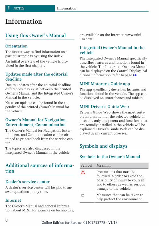
Symbols in the Owner's Manual
Symbol Meaning
Precautions that must befollowed in order to avoid thepossibility of injury to yourselfand to others as well as seriousdamage to the vehicle.
Measures that can be taken tohelp protect the environment.
Seite 8
NOTES Information
8Online Edition for Part no. 01402723778 - VI/18
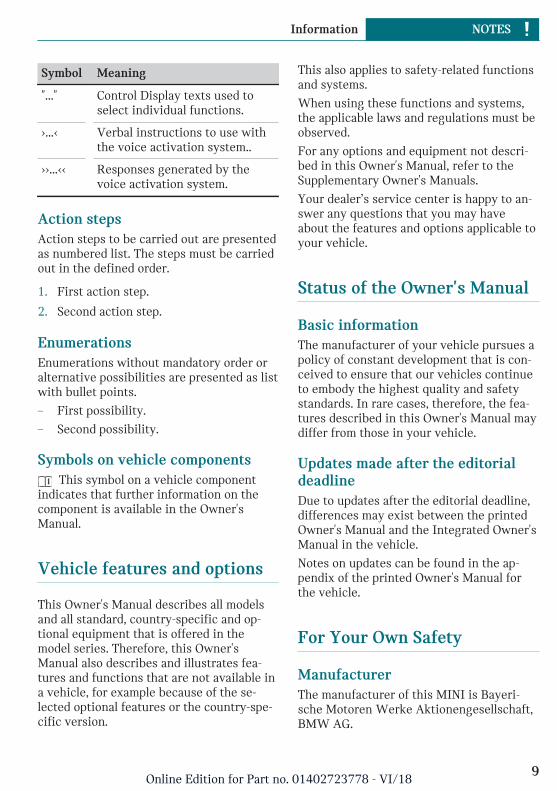
Symbol Meaning
"..." Control Display texts used toselect individual functions.
›...‹ Verbal instructions to use withthe voice activation system..
››...‹‹ Responses generated by thevoice activation system.
Action stepsAction steps to be carried out are presentedas numbered list. The steps must be carriedout in the defined order.
1. First action step.
2. Second action step.
EnumerationsEnumerations without mandatory order oralternative possibilities are presented as listwith bullet points.
– First possibility.
– Second possibility.
Symbols on vehicle components This symbol on a vehicle component
indicates that further information on thecomponent is available in the Owner'sManual.
Vehicle features and options
This Owner's Manual describes all modelsand all standard, country-specific and op-tional equipment that is offered in themodel series. Therefore, this Owner'sManual also describes and illustrates fea-tures and functions that are not available ina vehicle, for example because of the se-lected optional features or the country-spe-cific version.
This also applies to safety-related functionsand systems.
When using these functions and systems,the applicable laws and regulations must beobserved.
For any options and equipment not descri-bed in this Owner's Manual, refer to theSupplementary Owner's Manuals.
Your dealer’s service center is happy to an-swer any questions that you may haveabout the features and options applicable toyour vehicle.
Status of the Owner's Manual
Basic informationThe manufacturer of your vehicle pursues apolicy of constant development that is con-ceived to ensure that our vehicles continueto embody the highest quality and safetystandards. In rare cases, therefore, the fea-tures described in this Owner's Manual maydiffer from those in your vehicle.
Updates made after the editorialdeadlineDue to updates after the editorial deadline,differences may exist between the printedOwner's Manual and the Integrated Owner'sManual in the vehicle.
Notes on updates can be found in the ap-pendix of the printed Owner's Manual forthe vehicle.
For Your Own Safety
ManufacturerThe manufacturer of this MINI is Bayeri-sche Motoren Werke Aktionengesellschaft,BMW AG.
Seite 9
Information NOTES
9Online Edition for Part no. 01402723778 - VI/18
Intended useFollow the following when using the vehi-cle:
– Owner's Manual.
– Information on the vehicle. Do not re-move stickers.
– Technical vehicle data.
– The traffic, speed, and safety laws wherethe vehicle is driven.
– Vehicle documents and statutory docu-ments.
WarrantyYour vehicle is technically configured forthe operating conditions and registrationrequirements applying in the country offirst delivery, also known as homologation.If your vehicle is to be operated in a differ-ent country it might be necessary to adaptyour vehicle to potentially differing operat-ing conditions and registration require-ments. If your vehicle does not comply withthe homologation requirements in a certaincountry you may not be able to lodge war-ranty claims for your vehicle there. Furtherinformation on warranty is available from adealer’s service center.
Maintenance and repairs
WARNING
Improperly performed work on the vehiclepaint can lead to a failure or malfunctionof the radar sensors and thereby result in asafety risk. There is a risk of accidents orrisk of damage to property. Have paint-work or paintwork repairs on bumpers ofvehicles with radar sensors performed by adealer’s service center or another qualifiedservice center or repair shop only.
Advanced technology, e. g. the use of mod-ern materials and high-performance elec-
tronics, requires suitable maintenance andrepair work.
The manufacturer of your vehicle recom-mends that you entrust corresponding pro-cedures to a MINI dealer’s service center. Ifyou choose to use another service facility,the manufacturer of your vehicle recom-mends use of a facility that performs work,for instance maintenance and repair, ac-cording to MINI specifications with prop-erly trained personnel, referred to in thisOwner's Manual as "another qualified serv-ice center or repair shop".
If work is performed improperly, for in-stance maintenance and repair, there is arisk of subsequent damage and relatedsafety risks.
Parts and accessoriesThe manufacturer of your vehicle recom-mends the use of parts and accessory prod-ucts approved by the manufacturer of theMINI.
Approved parts and accessories, and adviceon their use and installation are availablefrom a MINI dealer's service center.
MINI parts and accessories were tested bythe manufacturer of the MINI for theirsafety and suitability in MINI vehicles.
The manufacturer of your vehicle warrantsgenuine MINI parts and accessories.
The manufacturer of your vehicle does notevaluate whether each individual productfrom another manufacturer can be usedwith MINI vehicles without presenting asafety hazard, even if a country-specific of-ficial approval was issued. The manufac-turer of your vehicle does not evaluatewhether these products are suitable forMINI vehicles under all usage conditions.
California Proposition 65 WarningCalifornia law requires vehicle manufactur-ers provide the following warning:
Seite 10
NOTES Information
10Online Edition for Part no. 01402723778 - VI/18
WARNING
Engine exhaust and a wide variety of Au-tomobile components and parts, includingcomponents found in the interior furnish-ings in a vehicle, contain or emit chemi-cals known to the State of California tocause cancer and birth defects and repro-ductive harm. In addition, certain fluidscontained in vehicles and certain productsof component wear contain or emit chemi-cals known to the State of California tocause cancer and birth defects or other re-productive harm. Battery posts, terminalsand related accessories contain lead andlead compounds. Batteries also containother chemicals known to the State of Cali-fornia to cause cancer. Wash your handsafter handling. Used engine oil containschemicals that have caused cancer in labo-ratory animals. Always protect your skinby washing thoroughly with soap and wa-ter. For more information go towww.P65Warnings.ca.gov/passenger-ve-hicle.
WARNING
Operating, servicing and maintaining apassenger vehicle or off-highway motorvehicle can expose you to chemicals in-cluding engine exhaust, carbon monoxide,phthalates, and lead, which are known tothe State of California to cause cancer andbirth defects or other reproductive harm.To minimize exposure, avoid breathing ex-haust, do not idle the engine except asnecessary, service your vehicle in a well-ventilated area and wear gloves or washyour hands frequently when servicingyour vehicle. For more information go towww.P65Warnings.ca.gov/passenger-ve-hicle.
Service and warrantyWe recommend that you read this publica-tion thoroughly. Your vehicle is covered bythe following warranties:
– New Vehicle Limited Warranty.
– Rust Perforation Limited Warranty.
– Federal Emissions System Defect War-ranty.
– Federal Emissions Performance War-ranty.
– California Emission Control System Lim-ited Warranty.
Detailed information about these warrantiesis listed in the Service and Warranty Infor-mation Booklet for US models or in the War-ranty and Service Guide Booklet for Cana-dian models.
Your vehicle has been specifically adaptedand designed to meet the particular operat-ing conditions and homologation require-ments in your country and continental re-gion in order to deliver the full drivingpleasure while the vehicle is operated underthose conditions. If you wish to operateyour vehicle in another country or region,you may be required to adapt your vehicleto meet different prevailing operating con-ditions and homologation requirements.You should also be aware of any applicablewarranty limitations or exclusions for suchcountry or region. In such case, please con-tact Customer Relations for further informa-tion.
MaintenanceMaintain the vehicle regularly to sustainthe road safety, operational reliability andthe New Vehicle Limited Warranty.
Specifications for required maintenancemeasures:
– MINI Maintenance system.
Seite 11
Information NOTES
11Online Edition for Part no. 01402723778 - VI/18
– Service and Warranty Information Book-let for US models.
– Warranty and Service Guide Booklet forCanadian models.
If the vehicle is not maintained according tothese specifications, this could result in se-rious damage to the vehicle. Such damage isnot covered by the MINI New Vehicle Lim-ited Warranty.
Data memory
General informationElectronic control devices are installed inthe vehicle. Electronic control units processdata they receive from vehicle sensors, self-generate or exchange with each other. Somecontrol units are necessary for the vehicleto function safely or provide assistance dur-ing driving, for instance driver assistancesystems. Furthermore, control devices facil-itate comfort or infotainment functions.
Information about stored or exchanged datacan be requested from the manufacturer ofthe vehicle, in a separate booklet, for exam-ple.
Personal referenceEach vehicle is marked with a unique vehi-cle identification number. Depending on thecountry, the vehicle owner can be identifiedwith the vehicle identification number, li-cense plate and corresponding authorities.In addition, there are other options to trackdata collected in the vehicle to the driver orvehicle owner, e.g. via utilized services.
Operating data in the vehicleControl units process data to operate the ve-hicle.
For example, this includes:
– Status messages for the vehicle and itsindividual components, e.g., wheel rota-tional speed, wheel speed, deceleration,transverse acceleration, engaged safetybelt indicator.
– Ambient conditions, e.g., temperature,rain sensor signals.
The processed data is only processed in thevehicle itself and generally volatile. Thedata is not stored beyond the operating pe-riod.
Electronic components, e.g. control unitsand ignition keys, contain components forstoring technical information. Informationabout the vehicle condition, component us-age, maintenance requirements or faultscan be stored temporarily or permanently.
This information generally records the stateof a component, a module, a system, or theenvironment, for instance:
– Operating states of system components,e.g., fill levels, tire inflation pressure,battery status.
– Malfunctions and faults in importantsystem components, for instance lightsand brakes.
– Responses by the vehicle to special sit-uations such as airbag deployment orengagement of the driving stability con-trol systems.
– Information on vehicle-damagingevents.
The data is required to perform the controldevice functions. Furthermore, it alsoserves to recognize and correct malfunc-tions, and helps the vehicle manufacturer tooptimize vehicle functions.
The majority of this data is transient and isonly processed within the vehicle itself.Only a small share of the data is storedevent-related in event or fault memories.
When servicing, for instance during repairs,service processes, warranty cases, and qual-
Seite 12
NOTES Information
12Online Edition for Part no. 01402723778 - VI/18
ity assurance measures, this technical infor-mation can be read out from the vehicle to-gether with the vehicle identificationnumber.
A dealer’s service center or another quali-fied service center or repair shop can readout the information. The socket for OBD On-board Diagnosis required by law in the ve-hicle is used to read out the data.
The data is collected, processed, and usedby the relevant organizations in the servicenetwork. The data documents technical con-ditions of the vehicle, helps with the identi-fication of the fault, compliance with war-ranty obligations and quality improvement.
Furthermore, the manufacturer has productmonitoring duties to meet in line with prod-uct liability law. To fulfill these duties, thevehicle manufacturer needs technical datafrom the vehicle. The data from the vehiclecan also be used to check customer claimsfor warranty and guaranty.
Fault and event memories in the vehicle canbe reset when a dealer’s service center oranother qualified service center or repairshop performs repair or servicing work.
Data entry and data transfer intothe vehicle
General informationDepending on the vehicle equipment, com-fort and individual settings can be stored inthe vehicle and modified or reset at anytime.
For example, this includes:
– Settings for the seat and steering wheelpositions.
– Suspension and climate control settings.
If necessary, data can be transferred to theentertainment and communication systemof the vehicle, e.g. via smartphone.
This includes the following depending onthe respective equipment:
– Multimedia data such as music, films orphotos for playback in an integratedmultimedia system.
– Address book data for use in conjunc-tion with an integrated hands-free sys-tem or an integrated navigation system.
– Entered navigation destinations.
– Data on the use of Internet services.
This data can be stored locally in the vehicleor is found on a device that has been con-nected to the vehicle, e.g., a smartphone,USB stick or MP3 player. If this data isstored in the vehicle, it can be deleted atany time.
This data is only transmitted to third partiesupon personal request as part of the use ofonline services. This depends on the se-lected settings for the use of the services.
Incorporation of mobile end devicesDepending on the vehicle equipment, mo-bile devices connected to the vehicle, for in-stance smartphones, can be controlled viathe vehicle control elements.
The sound and picture from the mobile de-vice can be played back and displayedthrough the multimedia system. Certain in-formation is transferred to the mobile de-vice at the same time. Depending on thetype of incorporation, this includes, for in-stance position data and other general vehi-cle information. This optimizes the way inwhich selected apps, for instance navigationor music playback, work.
There is no further interaction between themobile device and the vehicle, for instanceactive access to vehicle data.
How the data will be processed further isdetermined by the provider of the particularapp being used. The extent of the possible
Seite 13
Information NOTES
13Online Edition for Part no. 01402723778 - VI/18
settings depends on the respective app andthe operating system of the mobile device.
Services
General informationIf the vehicle has a wireless network con-nection, this enables data to be exchangedbetween the vehicle and other systems. Thewireless network connection is realized viaan in-vehicle transmitter and receiver unitor via personal mobile devices brought intothe vehicle, for instance smartphones. Thiswireless network connection enables 'onlinefunctions' to be used. These include onlineservices and apps supplied by the vehiclemanufacturer or by other providers.
Services from the vehiclemanufacturerWhere online services from the vehiclemanufacturer are concerned, the corre-sponding functions are described in the ap-propriate place, for instance the Owner'sManual or manufacturer's website. The rele-vant legal information pertaining to dataprotection is provided there too. Personaldata may be used to perform online serv-ices. Data is exchanged over a secure con-nection, for instance with the IT systems ofthe vehicle manufacturer intended for thispurpose.
Any collection, processing, and use of per-sonal data above and beyond that needed toprovide the services must always be basedon a legal permission, contractual arrange-ment or consent. It is also possible to acti-vate or deactivate the data connection as awhole. That is, with the exception of func-tions and services required by law such asAssist systems.
Services from other providersWhen using online services from other pro-viders, these services are the responsibility
of the relevant provider and subject to theirdata privacy conditions and terms of use.The vehicle manufacturer has no influenceon the content exchanged during this proc-ess. Information on the way in which per-sonal data is collected and used in relationto services from third parties, the scope ofsuch data, and its purpose, can be obtainedfrom the relevant service provider.
Event Data Recorder EDR
This vehicle is equipped with an event datarecorder EDR. The main purpose of an EDRis to record, in certain crash or near crash-like situations, such as an air bag deploy-ment or hitting a road obstacle, data thatwill assist in understanding how a vehicle’ssystems performed. The EDR is designed torecord data related to vehicle dynamics andsafety systems for a short period of time,typically 30 seconds or less.
The EDR in this vehicle is designed to re-cord such data as:
– How various systems in your vehiclewere operating.
– Whether or not the driver and passen-ger safety belts were fastened.
– How far, if at all, the driver was depress-ing the accelerator and/or brake pedal.
– How fast the vehicle was traveling.
This data can help provide a better under-standing of the circumstances in whichcrashes and injuries occur.
EDR data is recorded by your vehicle only ifa nontrivial crash situation occurs; no datais recorded by the EDR under normal driv-ing conditions and no personal data, for in-stance name, gender, age, and crash loca-tion, are recorded.
However, other parties, such as law enforce-ment, could combine the EDR data with the
Seite 14
NOTES Information
14Online Edition for Part no. 01402723778 - VI/18
type of personally identifying data routinelyacquired during a crash investigation.
To read data recorded by an EDR, specialequipment is required, and access to the ve-hicle or the EDR is needed. In addition tothe vehicle manufacturer, other parties,such as law enforcement, that have the spe-cial equipment, can read the information ifthey have access to the vehicle or the EDR.
Vehicle identification number
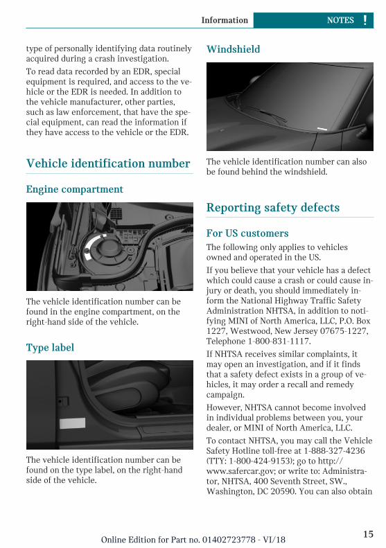
Engine compartment
The vehicle identification number can befound in the engine compartment, on theright-hand side of the vehicle.
Type label
The vehicle identification number can befound on the type label, on the right-handside of the vehicle.
Windshield
The vehicle identification number can alsobe found behind the windshield.
Reporting safety defects
For US customersThe following only applies to vehiclesowned and operated in the US.
If you believe that your vehicle has a defectwhich could cause a crash or could cause in-jury or death, you should immediately in-form the National Highway Traffic SafetyAdministration NHTSA, in addition to noti-fying MINI of North America, LLC, P.O. Box1227, Westwood, New Jersey 07675-1227,Telephone 1-800-831-1117.
If NHTSA receives similar complaints, itmay open an investigation, and if it findsthat a safety defect exists in a group of ve-hicles, it may order a recall and remedycampaign.
However, NHTSA cannot become involvedin individual problems between you, yourdealer, or MINI of North America, LLC.
To contact NHTSA, you may call the VehicleSafety Hotline toll-free at 1-888-327-4236(TTY: 1-800-424-9153); go to http://www.safercar.gov; or write to: Administra-tor, NHTSA, 400 Seventh Street, SW.,Washington, DC 20590. You can also obtain
Seite 15
Information NOTES
15Online Edition for Part no. 01402723778 - VI/18
other information about motor vehiclesafety from http://www.safercar.gov
For Canadian customersCanadian customers who wish to report asafety-related defect to Transport Canada,Defect Investigations and Recalls, may callthe toll-free hotline 1-800-333-0510. Youcan also obtain other information about mo-tor vehicle safety from http://www.tc.gc.ca/roadsafety.
Seite 16
NOTES Information
16Online Edition for Part no. 01402723778 - VI/18

Seite 17
Information NOTES
17Online Edition for Part no. 01402723778 - VI/18

18
Online Edition for Part no. 01402723778 - VI/18

QUICK REFERENCE
Your MINI at a glance ............................................................................ 20
19Online Edition for Part no. 01402723778 - VI/18
Your MINI at a glance
Opening and closing
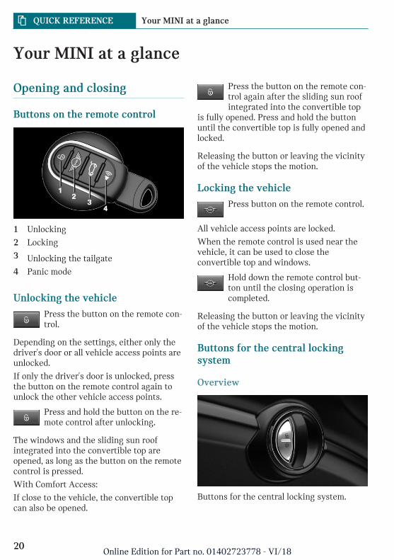
Buttons on the remote control
1 Unlocking
2 Locking
3 Unlocking the tailgate
4 Panic mode
Unlocking the vehiclePress the button on the remote con-trol.
Depending on the settings, either only thedriver's door or all vehicle access points areunlocked.
If only the driver's door is unlocked, pressthe button on the remote control again tounlock the other vehicle access points.
Press and hold the button on the re-mote control after unlocking.
The windows and the sliding sun roofintegrated into the convertible top areopened, as long as the button on the remotecontrol is pressed.
With Comfort Access:
If close to the vehicle, the convertible topcan also be opened.
Press the button on the remote con-trol again after the sliding sun roofintegrated into the convertible top
is fully opened. Press and hold the buttonuntil the convertible top is fully opened andlocked.
Releasing the button or leaving the vicinityof the vehicle stops the motion.
Locking the vehiclePress button on the remote control.
All vehicle access points are locked.
When the remote control is used near thevehicle, it can be used to close theconvertible top and windows.
Hold down the remote control but-ton until the closing operation iscompleted.
Releasing the button or leaving the vicinityof the vehicle stops the motion.
Buttons for the central lockingsystem
Overview
Buttons for the central locking system.
Seite 20
QUICK REFERENCE Your MINI at a glance
20Online Edition for Part no. 01402723778 - VI/18
Locking
Pressing the button locks the vehi-cle if the front doors are closed.
Unlocking
Pressing the button unlocks the ve-hicle.
Panic modeYou can trigger the alarm system if you findyourself in a dangerous situation.
Press button on the remote controland hold for at least 3 seconds.
To switch off the alarm: press any button.
Comfort Access
ConceptThe vehicle can be accessed without acti-vating the remote control.
All you need to do is to have the remotecontrol with you, such as in your pantspocket.
The vehicle automatically detects the re-mote control when it is in close proximityor in the car's interior.
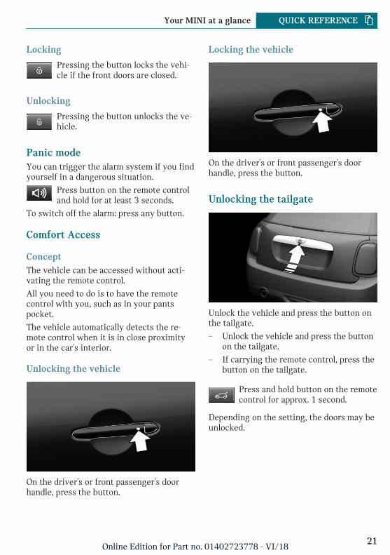
Unlocking the vehicle
On the driver's or front passenger's doorhandle, press the button.
Locking the vehicle
On the driver's or front passenger's doorhandle, press the button.
Unlocking the tailgate
Unlock the vehicle and press the button onthe tailgate.
– Unlock the vehicle and press the buttonon the tailgate.
– If carrying the remote control, press thebutton on the tailgate.
Press and hold button on the remotecontrol for approx. 1 second.
Depending on the setting, the doors may beunlocked.
Seite 21
Your MINI at a glance QUICK REFERENCE
21Online Edition for Part no. 01402723778 - VI/18
Convertible top with integratedsliding sun roof
Overview
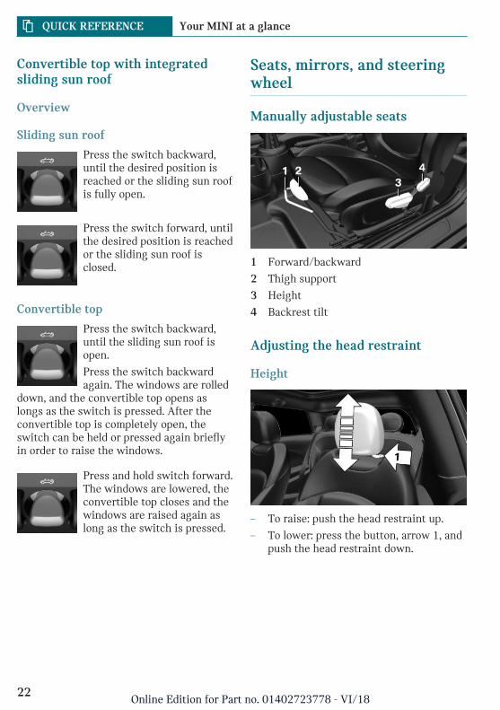
Sliding sun roof
Press the switch backward,until the desired position isreached or the sliding sun roofis fully open.
Press the switch forward, untilthe desired position is reachedor the sliding sun roof isclosed.
Convertible top
Press the switch backward,until the sliding sun roof isopen.
Press the switch backwardagain. The windows are rolled
down, and the convertible top opens aslongs as the switch is pressed. After theconvertible top is completely open, theswitch can be held or pressed again brieflyin order to raise the windows.
Press and hold switch forward.The windows are lowered, theconvertible top closes and thewindows are raised again aslong as the switch is pressed.
Seats, mirrors, and steeringwheel
Manually adjustable seats
1 Forward/backward
2 Thigh support
3 Height
4 Backrest tilt
Adjusting the head restraint
Height
– To raise: push the head restraint up.
– To lower: press the button, arrow 1, andpush the head restraint down.
Seite 22
QUICK REFERENCE Your MINI at a glance
22Online Edition for Part no. 01402723778 - VI/18
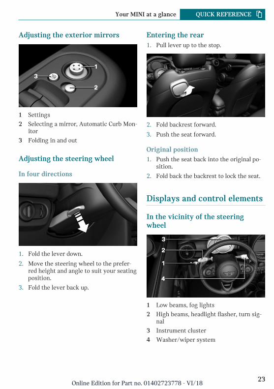
Adjusting the exterior mirrors
1 Settings
2 Selecting a mirror, Automatic Curb Mon-itor
3 Folding in and out
Adjusting the steering wheel
In four directions
1. Fold the lever down.
2. Move the steering wheel to the prefer-red height and angle to suit your seatingposition.
3. Fold the lever back up.
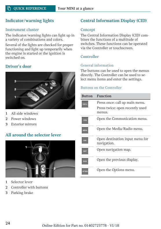
Entering the rear1. Pull lever up to the stop.
2. Fold backrest forward.
3. Push the seat forward.
Original position1. Push the seat back into the original po-
sition.
2. Fold back the backrest to lock the seat.
Displays and control elements
In the vicinity of the steeringwheel
1 Low beams, fog lights
2 High beams, headlight flasher, turn sig-nal
3 Instrument cluster
4 Washer/wiper system
Seite 23
Your MINI at a glance QUICK REFERENCE
23Online Edition for Part no. 01402723778 - VI/18
Indicator/warning lights
Instrument clusterThe indicator/warning lights can light up ina variety of combinations and colors.
Several of the lights are checked for properfunctioning and light up temporarily whenthe engine is started or the ignition isswitched on.
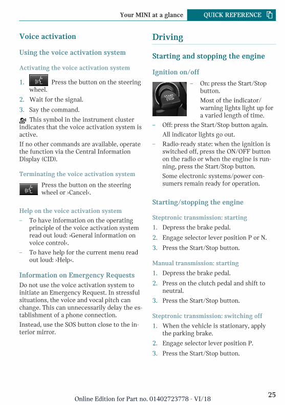
Driver's door
1 All side windows
2 Power windows
3 Exterior mirrors
All around the selector lever
1 Selector lever
2 Controller with buttons
3 Parking brake
Central Information Display (CID)
ConceptThe Central Information Display (CID) com-bines the functions of a multitude ofswitches. These functions can be operatedvia the Controller or touchscreen.
Controller
General information
The buttons can be used to open the menusdirectly. The Controller can be used to se-lect menu items and enter the settings.
Buttons on the Controller
Button Function
Press once: call up main menu.
Press twice: open recently usedmenus.
Open the Communication menu.
Open the Media/Radio menu.
Open destination input menu fornavigation.
Open navigation map.
Open the previous display.
Open the Options menu.
Seite 24
QUICK REFERENCE Your MINI at a glance
24Online Edition for Part no. 01402723778 - VI/18
Voice activation
Using the voice activation system
Activating the voice activation system
1. Press the button on the steeringwheel.
2. Wait for the signal.
3. Say the command.
This symbol in the instrument clusterindicates that the voice activation system isactive.
If no other commands are available, operatethe function via the Central InformationDisplay (CID).
Terminating the voice activation system
Press the button on the steeringwheel or ›Cancel‹.
Help on the voice activation system
– To have information on the operatingprinciple of the voice activation systemread out loud: ›General information onvoice control‹.
– To have help for the current menu readout loud: ›Help‹.
Information on Emergency RequestsDo not use the voice activation system toinitiate an Emergency Request. In stressfulsituations, the voice and vocal pitch canchange. This can unnecessarily delay the es-tablishment of a phone connection.
Instead, use the SOS button close to the in-terior mirror.
Driving
Starting and stopping the engine
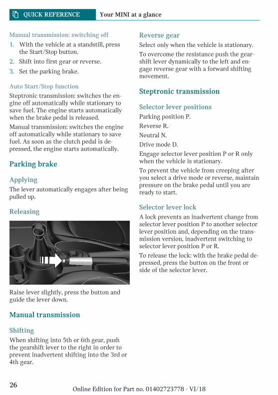
Ignition on/off
– On: press the Start/Stopbutton.
Most of the indicator/warning lights light up fora varied length of time.
– Off: press the Start/Stop button again.
All indicator lights go out.
– Radio-ready state: when the ignition isswitched off, press the ON/OFF buttonon the radio or when the engine is run-ning, press the Start/Stop button.
Some electronic systems/power con-sumers remain ready for operation.
Starting/stopping the engine
Steptronic transmission: starting
1. Depress the brake pedal.
2. Engage selector lever position P or N.
3. Press the Start/Stop button.
Manual transmission: starting
1. Depress the brake pedal.
2. Press on the clutch pedal and shift toneutral.
3. Press the Start/Stop button.
Steptronic transmission: switching off
1. When the vehicle is stationary, applythe parking brake.
2. Engage selector lever position P.
3. Press the Start/Stop button.
Seite 25
Your MINI at a glance QUICK REFERENCE
25Online Edition for Part no. 01402723778 - VI/18
Manual transmission: switching off
1. With the vehicle at a standstill, pressthe Start/Stop button.
2. Shift into first gear or reverse.
3. Set the parking brake.
Auto Start/Stop function
Steptronic transmission: switches the en-gine off automatically while stationary tosave fuel. The engine starts automaticallywhen the brake pedal is released.
Manual transmission: switches the engineoff automatically while stationary to savefuel. As soon as the clutch pedal is de-pressed, the engine starts automatically.
Parking brake
ApplyingThe lever automatically engages after beingpulled up.
Releasing
Raise lever slightly, press the button andguide the lever down.
Manual transmission
ShiftingWhen shifting into 5th or 6th gear, pushthe gearshift lever to the right in order toprevent inadvertent shifting into the 3rd or4th gear.
Reverse gearSelect only when the vehicle is stationary.
To overcome the resistance push the gear-shift lever dynamically to the left and en-gage reverse gear with a forward shiftingmovement.
Steptronic transmission
Selector lever positionsParking position P.
Reverse R.
Neutral N.
Drive mode D.
Engage selector lever position P or R onlywhen the vehicle is stationary.
To prevent the vehicle from creeping afteryou select a drive mode or reverse, maintainpressure on the brake pedal until you areready to start.
Selector lever lockA lock prevents an inadvertent change fromselector lever position P to another selectorlever position and, depending on the trans-mission version, inadvertent switching toselector lever position P or R.
To release the lock: with the brake pedal de-pressed, press the button on the front orside of the selector lever.
Seite 26
QUICK REFERENCE Your MINI at a glance
26Online Edition for Part no. 01402723778 - VI/18
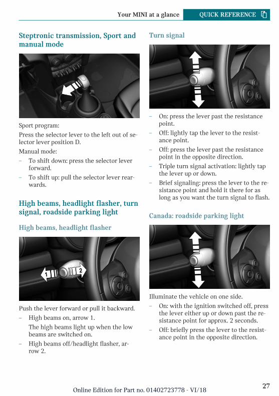
Steptronic transmission, Sport andmanual mode
Sport program:
Press the selector lever to the left out of se-lector lever position D.
Manual mode:
– To shift down: press the selector leverforward.
– To shift up: pull the selector lever rear-wards.
High beams, headlight flasher, turnsignal, roadside parking light
High beams, headlight flasher
Push the lever forward or pull it backward.
– High beams on, arrow 1.
The high beams light up when the lowbeams are switched on.
– High beams off/headlight flasher, ar-row 2.
Turn signal
– On: press the lever past the resistancepoint.
– Off: lightly tap the lever to the resist-ance point.
– Off: press the lever past the resistancepoint in the opposite direction.
– Triple turn signal activation: lightly tapthe lever up or down.
– Brief signaling: press the lever to the re-sistance point and hold it there for aslong as you want the turn signal to flash.
Canada: roadside parking light
Illuminate the vehicle on one side.
– On: with the ignition switched off, pressthe lever either up or down past the re-sistance point for approx. 2 seconds.
– Off: briefly press the lever to the resist-ance point in the opposite direction.
Seite 27
Your MINI at a glance QUICK REFERENCE
27Online Edition for Part no. 01402723778 - VI/18
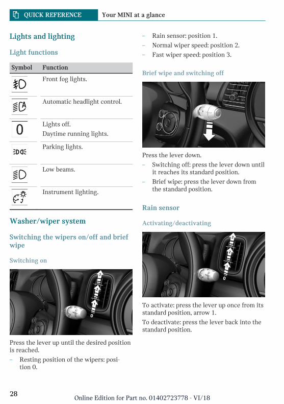
Lights and lighting
Light functions
Symbol Function
Front fog lights.
Automatic headlight control.
Lights off.
Daytime running lights.
Parking lights.
Low beams.
Instrument lighting.
Washer/wiper system
Switching the wipers on/off and briefwipe
Switching on
Press the lever up until the desired positionis reached.
– Resting position of the wipers: posi-tion 0.
– Rain sensor: position 1.
– Normal wiper speed: position 2.
– Fast wiper speed: position 3.
Brief wipe and switching off
Press the lever down.
– Switching off: press the lever down untilit reaches its standard position.
– Brief wipe: press the lever down fromthe standard position.
Rain sensor
Activating/deactivating
To activate: press the lever up once from itsstandard position, arrow 1.
To deactivate: press the lever back into thestandard position.
Seite 28
QUICK REFERENCE Your MINI at a glance
28Online Edition for Part no. 01402723778 - VI/18
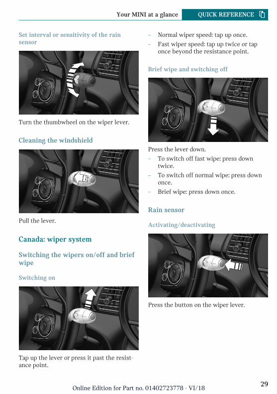
Set interval or sensitivity of the rainsensor
Turn the thumbwheel on the wiper lever.
Cleaning the windshield
Pull the lever.
Canada: wiper system
Switching the wipers on/off and briefwipe
Switching on
Tap up the lever or press it past the resist-ance point.
– Normal wiper speed: tap up once.
– Fast wiper speed: tap up twice or taponce beyond the resistance point.
Brief wipe and switching off
Press the lever down.
– To switch off fast wipe: press downtwice.
– To switch off normal wipe: press downonce.
– Brief wipe: press down once.
Rain sensor
Activating/deactivating
Press the button on the wiper lever.
Seite 29
Your MINI at a glance QUICK REFERENCE
29Online Edition for Part no. 01402723778 - VI/18
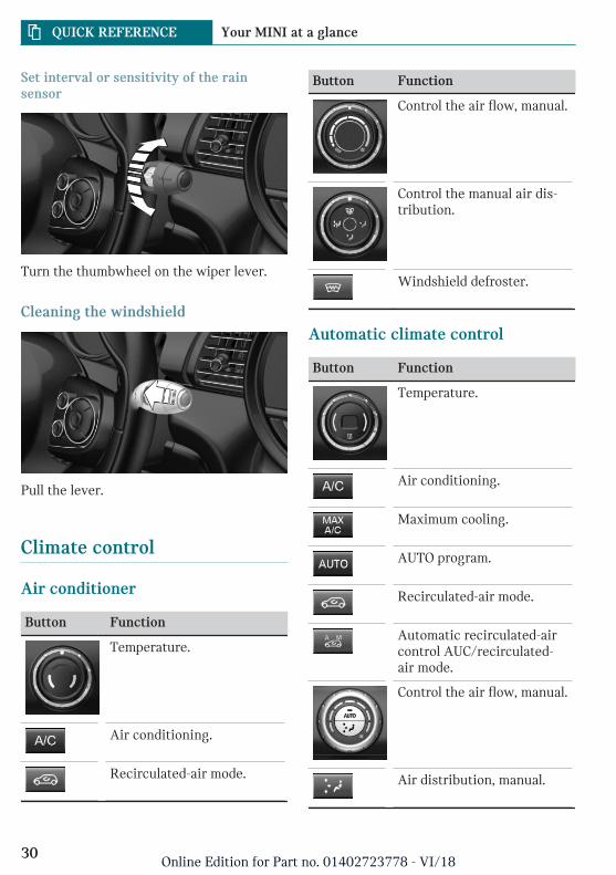
Set interval or sensitivity of the rainsensor
Turn the thumbwheel on the wiper lever.
Cleaning the windshield
Pull the lever.
Climate control
Air conditioner
Button Function
Temperature.
Air conditioning.
Recirculated-air mode.
Button Function
Control the air flow, manual.
Control the manual air dis-tribution.
Windshield defroster.
Automatic climate control
Button Function
Temperature.
Air conditioning.
Maximum cooling.
AUTO program.
Recirculated-air mode.
Automatic recirculated-aircontrol AUC/recirculated-air mode.
Control the air flow, manual.
Air distribution, manual.
Seite 30
QUICK REFERENCE Your MINI at a glance
30Online Edition for Part no. 01402723778 - VI/18
Button Function
Defrost and defog the win-dows.
Windshield defroster.
Rear window defroster.
Infotainment
Radio
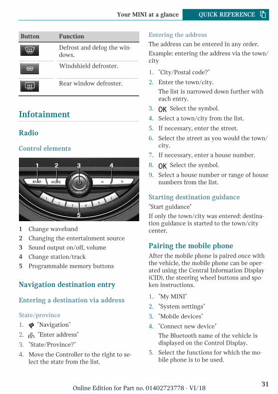
Control elements
1 Change waveband
2 Changing the entertainment source
3 Sound output on/off, volume
4 Change station/track
5 Programmable memory buttons
Navigation destination entry
Entering a destination via address
State/province
1. "Navigation"
2. "Enter address"
3. "State/Province?"
4. Move the Controller to the right to se-lect the state from the list.
Entering the address
The address can be entered in any order.
Example: entering the address via the town/city
1. "City/Postal code?"
2. Enter the town/city.
The list is narrowed down further witheach entry.
3. Select the symbol.
4. Select a town/city from the list.
5. If necessary, enter the street.
6. Select the street as you would the town/city.
7. If necessary, enter a house number.
8. Select the symbol.
9. Select a house number or range of housenumbers from the list.
Starting destination guidance"Start guidance"
If only the town/city was entered: destina-tion guidance is started to the town/citycenter.
Pairing the mobile phoneAfter the mobile phone is paired once withthe vehicle, the mobile phone can be oper-ated using the Central Information Display(CID), the steering wheel buttons and spo-ken instructions.
1. "My MINI"
2. "System settings"
3. "Mobile devices"
4. "Connect new device"
The Bluetooth name of the vehicle isdisplayed on the Control Display.
5. Select the functions for which the mo-bile phone is to be used.
Seite 31
Your MINI at a glance QUICK REFERENCE
31Online Edition for Part no. 01402723778 - VI/18
6. To perform additional steps on the mo-bile phone, refer to the mobile phoneowner's manual: e.g., search for or con-nect the Bluetooth device or a new de-vice.
The Bluetooth name of the vehicle ap-pears on the mobile phone display. Se-lect the Bluetooth name of the vehicle.
7. Depending on the mobile device, a con-trol number is displayed or the controlnumber must be entered.
– Compare the control number dis-played on the Control Display withthe control number on the display ofthe device.
Confirm the control number on thedevice and on the Control Display.
– Enter and confirm the same controlnumber on the device and via theCentral Information Display (CID).
The device is connected and displayedin the device list.
The mobile phone is connected and will ap-pear at the top of the list of mobile phones.
Using the phone
Accepting a callIncoming call can be accepted via the Cen-tral Information Display (CID) or the buttonon the steering wheel.
Via the Central Information Display (CID)
"Accept"
Via the button on the steering wheel
Press button.
Via the instrument cluster
Use the OK button on the steering wheel toselect: "Accept"
Dialing a number1. "Communication"
2. "Dial number"
3. Select the numbers individually.
4. Select the symbol.
If connection is to be set up via the addi-tional phone:
1. Press button.
2. "Call via"
Apple CarPlay preparation
ConceptCarPlay allows certain functions of a com-patible Apple iPhone to be used via Sirivoice operation and the Central InformationDisplay (CID).
Functional requirements– Compatible iPhone.
iPhone 5 or later with iOS 7.1 or later.
– Corresponding mobile wireless contract.
– Bluetooth, WiFi, and Siri voice opera-tion are switched on on the iPhone.
Switching on Bluetooth and CarPlayVia the Central Information Display (CID):
1. "My MINI"
2. "System settings"
3. "Mobile devices"
4. "Settings"
5. Select the following settings:
– "Bluetooth®"
– "Apple CarPlay"
Seite 32
QUICK REFERENCE Your MINI at a glance
32Online Edition for Part no. 01402723778 - VI/18
Pairing iPhone with CarPlayPair iPhone via Bluetooth with the vehicle.
Select CarPlay as the function:
"Apple CarPlay"
The iPhone is connected to the vehicle anddisplayed in the device list.
Refueling
Refueling
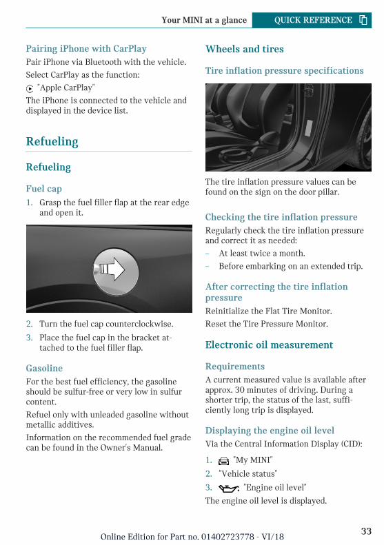
Fuel cap1. Grasp the fuel filler flap at the rear edge
and open it.
2. Turn the fuel cap counterclockwise.
3. Place the fuel cap in the bracket at-tached to the fuel filler flap.
GasolineFor the best fuel efficiency, the gasolineshould be sulfur-free or very low in sulfurcontent.
Refuel only with unleaded gasoline withoutmetallic additives.
Information on the recommended fuel gradecan be found in the Owner's Manual.
Wheels and tires
Tire inflation pressure specifications
The tire inflation pressure values can befound on the sign on the door pillar.
Checking the tire inflation pressureRegularly check the tire inflation pressureand correct it as needed:
– At least twice a month.
– Before embarking on an extended trip.
After correcting the tire inflationpressureReinitialize the Flat Tire Monitor.
Reset the Tire Pressure Monitor.
Electronic oil measurement
RequirementsA current measured value is available afterapprox. 30 minutes of driving. During ashorter trip, the status of the last, suffi-ciently long trip is displayed.
Displaying the engine oil levelVia the Central Information Display (CID):
1. "My MINI"
2. "Vehicle status"
3. "Engine oil level"
The engine oil level is displayed.
Seite 33
Your MINI at a glance QUICK REFERENCE
33Online Edition for Part no. 01402723778 - VI/18
Adding engine oil
General informationSwitch off the ignition and safely park thevehicle before engine oil is added.
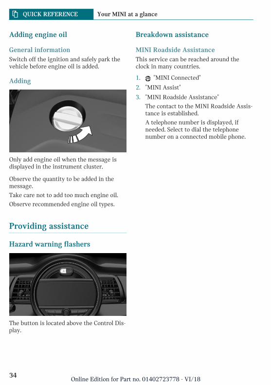
Adding
Only add engine oil when the message isdisplayed in the instrument cluster.
Observe the quantity to be added in themessage.
Take care not to add too much engine oil.
Observe recommended engine oil types.
Providing assistance
Hazard warning flashers
The button is located above the Control Dis-play.
Breakdown assistance
MINI Roadside AssistanceThis service can be reached around theclock in many countries.
1. "MINI Connected"
2. "MINI Assist"
3. "MINI Roadside Assistance"
The contact to the MINI Roadside Assis-tance is established.
A telephone number is displayed, ifneeded. Select to dial the telephonenumber on a connected mobile phone.
Seite 34
QUICK REFERENCE Your MINI at a glance
34Online Edition for Part no. 01402723778 - VI/18

Seite 35
Your MINI at a glance QUICK REFERENCE
35Online Edition for Part no. 01402723778 - VI/18

36
Online Edition for Part no. 01402723778 - VI/18
AT A GLANCE
Cockpit ........................................................................................................ 38Central Information Display (CID) ...................................................... 42Voice activation system ......................................................................... 51General settings ....................................................................................... 54Owner's Manual media ........................................................................... 66
37Online Edition for Part no. 01402723778 - VI/18
Cockpit
Vehicle features and options
This chapter describes all standard, country-specific and optional features offered withthe series. It also describes features that arenot necessarily available in your vehicle,
e. g., due to the selected options or countryversions. This also applies to safety-relatedfunctions and systems. When using thesefunctions and systems, the applicable lawsand regulations must be observed.
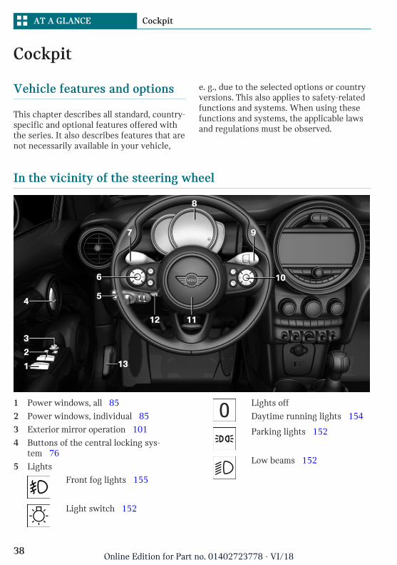
In the vicinity of the steering wheel
1 Power windows, all 85
2 Power windows, individual 85
3 Exterior mirror operation 101
4 Buttons of the central locking sys-tem 76
5 Lights
Front fog lights 155
Light switch 152
Lights off
Daytime running lights 154
Parking lights 152
Low beams 152
Seite 38
AT A GLANCE Cockpit
38Online Edition for Part no. 01402723778 - VI/18
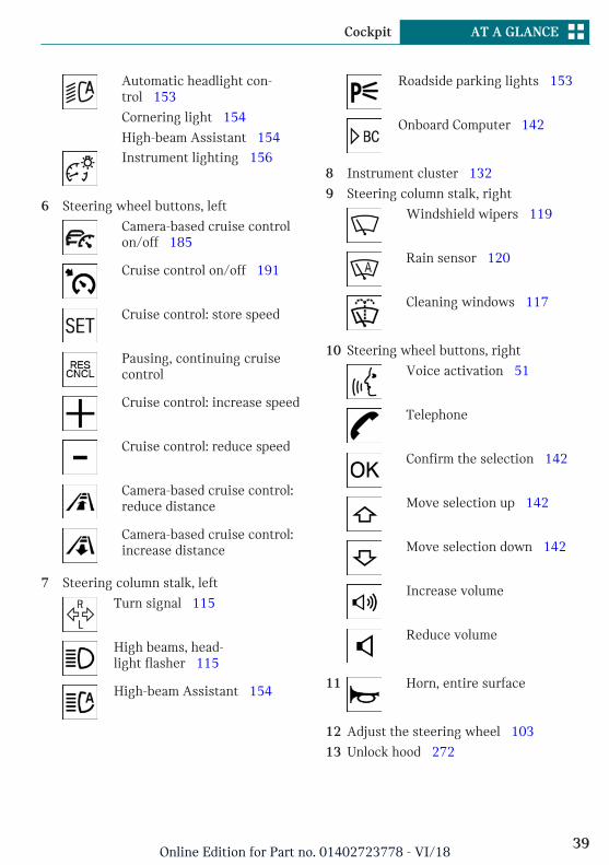
Automatic headlight con-trol 153
Cornering light 154
High-beam Assistant 154Instrument lighting 156
6 Steering wheel buttons, left
Camera-based cruise controlon/off 185
Cruise control on/off 191
Cruise control: store speed
Pausing, continuing cruisecontrol
Cruise control: increase speed
Cruise control: reduce speed
Camera-based cruise control:reduce distance
Camera-based cruise control:increase distance
7 Steering column stalk, left
Turn signal 115
High beams, head-light flasher 115
High-beam Assistant 154
Roadside parking lights 153
Onboard Computer 142
8 Instrument cluster 132
9 Steering column stalk, right
Windshield wipers 119
Rain sensor 120
Cleaning windows 117
10 Steering wheel buttons, right
Voice activation 51
Telephone
Confirm the selection 142
Move selection up 142
Move selection down 142
Increase volume
Reduce volume
11 Horn, entire surface
12 Adjust the steering wheel 103
13 Unlock hood 272
Seite 39
Cockpit AT A GLANCE
39Online Edition for Part no. 01402723778 - VI/18
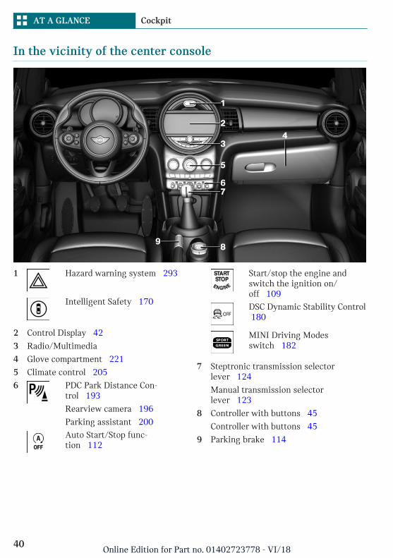
In the vicinity of the center console
1 Hazard warning system 293
Intelligent Safety 170
2 Control Display 42
3 Radio/Multimedia
4 Glove compartment 221
5 Climate control 205
6 PDC Park Distance Con-trol 193
Rearview camera 196
Parking assistant 200Auto Start/Stop func-tion 112
Start/stop the engine andswitch the ignition on/off 109DSC Dynamic Stability Control 180
MINI Driving Modesswitch 182
7 Steptronic transmission selectorlever 124
Manual transmission selectorlever 123
8 Controller with buttons 45
Controller with buttons 45
9 Parking brake 114
Seite 40
AT A GLANCE Cockpit
40Online Edition for Part no. 01402723778 - VI/18
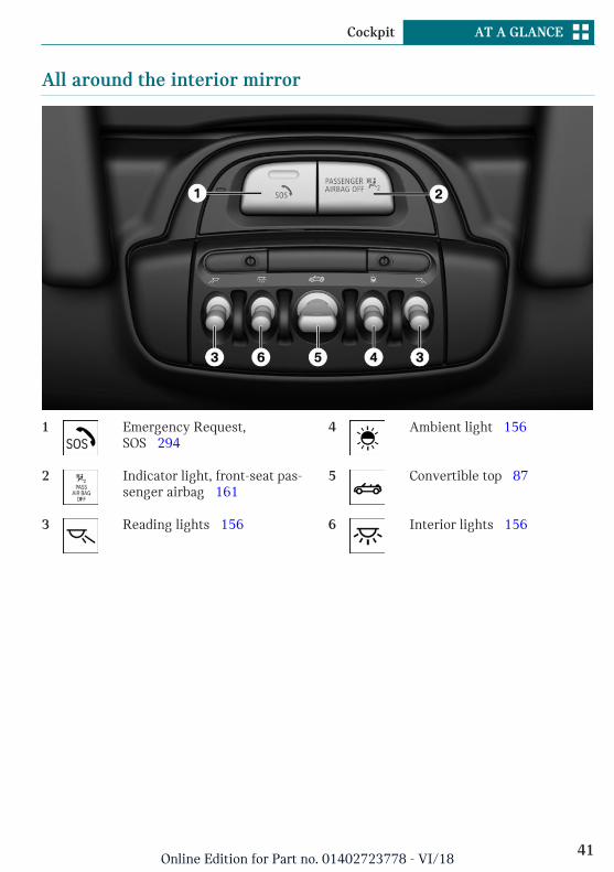
All around the interior mirror
1 Emergency Request,SOS 294
2 Indicator light, front-seat pas-senger airbag 161
3 Reading lights 156
4 Ambient light 156
5 Convertible top 87
6 Interior lights 156
Seite 41
Cockpit AT A GLANCE
41Online Edition for Part no. 01402723778 - VI/18
Central Information Display (CID)
Vehicle features and options
This chapter describes all standard, country-specific and optional features offered withthe series. It also describes features that arenot necessarily available in your vehicle,e. g., due to the selected options or countryversions. This also applies to safety-relatedfunctions and systems. When using thesefunctions and systems, the applicable lawsand regulations must be observed.
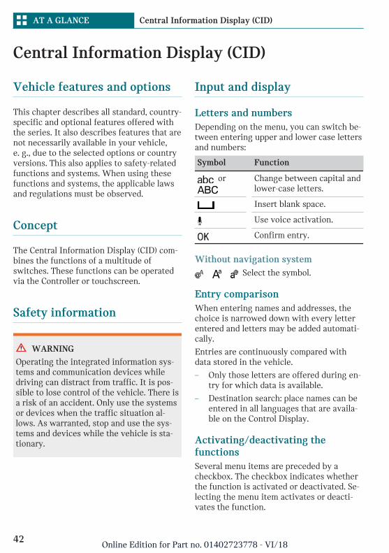
Concept
The Central Information Display (CID) com-bines the functions of a multitude ofswitches. These functions can be operatedvia the Controller or touchscreen.
Safety information
WARNING
Operating the integrated information sys-tems and communication devices whiledriving can distract from traffic. It is pos-sible to lose control of the vehicle. There isa risk of an accident. Only use the systemsor devices when the traffic situation al-lows. As warranted, stop and use the sys-tems and devices while the vehicle is sta-tionary.
Input and display
Letters and numbersDepending on the menu, you can switch be-tween entering upper and lower case lettersand numbers:
Symbol Function
or
Change between capital andlower-case letters.
Insert blank space.
Use voice activation.
Confirm entry.
Without navigation system Select the symbol.
Entry comparisonWhen entering names and addresses, thechoice is narrowed down with every letterentered and letters may be added automati-cally.
Entries are continuously compared withdata stored in the vehicle.
– Only those letters are offered during en-try for which data is available.
– Destination search: place names can beentered in all languages that are availa-ble on the Control Display.
Activating/deactivating thefunctionsSeveral menu items are preceded by acheckbox. The checkbox indicates whetherthe function is activated or deactivated. Se-lecting the menu item activates or deacti-vates the function.
Seite 42
AT A GLANCE Central Information Display (CID)
42Online Edition for Part no. 01402723778 - VI/18
Function is activated.
Function is deactivated.
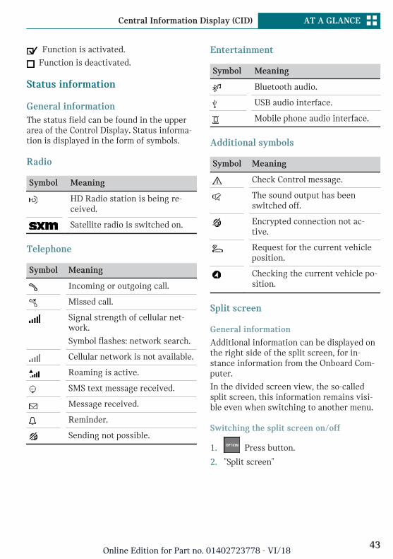
Status information
General informationThe status field can be found in the upperarea of the Control Display. Status informa-tion is displayed in the form of symbols.
Radio
Symbol Meaning
HD Radio station is being re-ceived.
Satellite radio is switched on.
Telephone
Symbol Meaning
Incoming or outgoing call.
Missed call.
Signal strength of cellular net-work.
Symbol flashes: network search.
Cellular network is not available.
Roaming is active.
SMS text message received.
Message received.
Reminder.
Sending not possible.
Entertainment
Symbol Meaning
Bluetooth audio.
USB audio interface.
Mobile phone audio interface.
Additional symbols
Symbol Meaning
Check Control message.
The sound output has beenswitched off.
Encrypted connection not ac-tive.
Request for the current vehicleposition.
Checking the current vehicle po-sition.
Split screen
General information
Additional information can be displayed onthe right side of the split screen, for in-stance information from the Onboard Com-puter.
In the divided screen view, the so-calledsplit screen, this information remains visi-ble even when switching to another menu.
Switching the split screen on/off
1. Press button.
2. "Split screen"
Seite 43
Central Information Display (CID) AT A GLANCE
43Online Edition for Part no. 01402723778 - VI/18
Selecting the display
The display can be selected in menus,where the split screen is supported.
1. Move the Controller to the right untilthe split screen is selected.
2. Press the Controller.
3. Select the desired setting.
Specifying the number of displays
It is possible to specify the number of dis-plays.
1. Move the Controller to the right untilthe split screen is selected.
2. Press the Controller.
3. "Personalize menu"
4. Select the desired setting.
5. Move the Controller to the left.
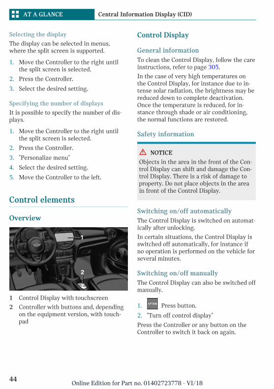
Control elements
Overview
1 Control Display with touchscreen
2 Controller with buttons and, dependingon the equipment version, with touch-pad
Control Display
General informationTo clean the Control Display, follow the careinstructions, refer to page 305.
In the case of very high temperatures onthe Control Display, for instance due to in-tense solar radiation, the brightness may bereduced down to complete deactivation.Once the temperature is reduced, for in-stance through shade or air conditioning,the normal functions are restored.
Safety information
NOTICE
Objects in the area in the front of the Con-trol Display can shift and damage the Con-trol Display. There is a risk of damage toproperty. Do not place objects in the areain front of the Control Display.
Switching on/off automaticallyThe Control Display is switched on automat-ically after unlocking.
In certain situations, the Control Display isswitched off automatically, for instance ifno operation is performed on the vehicle forseveral minutes.
Switching on/off manuallyThe Control Display can also be switched offmanually.
1. Press button.
2. "Turn off control display"
Press the Controller or any button on theController to switch it back on again.
Seite 44
AT A GLANCE Central Information Display (CID)
44Online Edition for Part no. 01402723778 - VI/18
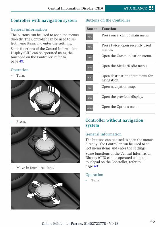
Controller with navigation system
General informationThe buttons can be used to open the menusdirectly. The Controller can be used to se-lect menu items and enter the settings.
Some functions of the Central InformationDisplay (CID) can be operated using thetouchpad on the Controller, refer topage 49:
Operation– Turn.
– Press.
– Move in four directions.
Buttons on the Controller
Button Function
Press once: call up main menu.
Press twice: open recently usedmenus.
Open the Communication menu.
Open the Media/Radio menu.
Open destination input menu fornavigation.
Open navigation map.
Open the previous display.
Open the Options menu.
Controller without navigationsystem
General informationThe buttons can be used to open the menusdirectly. The Controller can be used to se-lect menu items and enter the settings.
Some functions of the Central InformationDisplay (CID) can be operated using thetouchpad on the Controller, refer topage 49:
Operation– Turn.
Seite 45
Central Information Display (CID) AT A GLANCE
45Online Edition for Part no. 01402723778 - VI/18
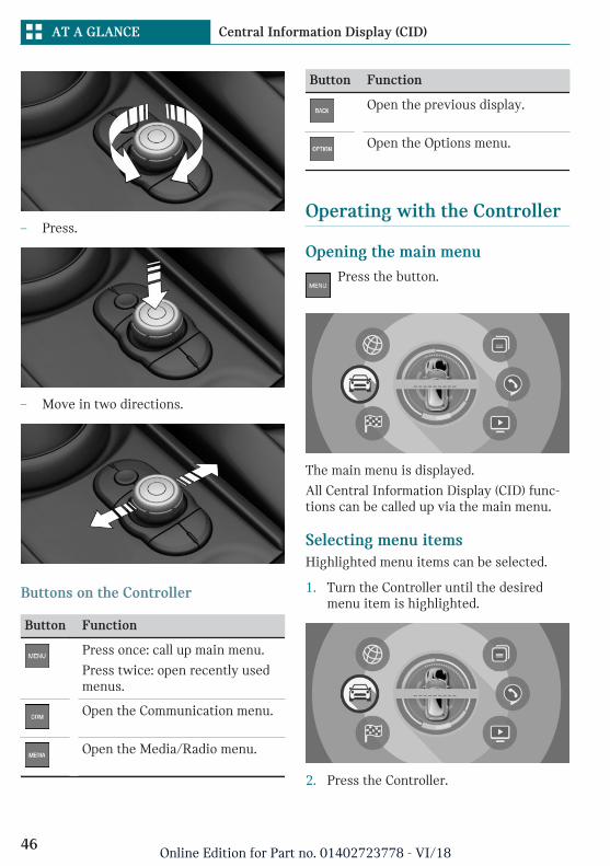
– Press.
– Move in two directions.
Buttons on the Controller
Button Function
Press once: call up main menu.
Press twice: open recently usedmenus.
Open the Communication menu.
Open the Media/Radio menu.
Button Function
Open the previous display.
Open the Options menu.
Operating with the Controller
Opening the main menuPress the button.
The main menu is displayed.
All Central Information Display (CID) func-tions can be called up via the main menu.
Selecting menu itemsHighlighted menu items can be selected.
1. Turn the Controller until the desiredmenu item is highlighted.
2. Press the Controller.
Seite 46
AT A GLANCE Central Information Display (CID)
46Online Edition for Part no. 01402723778 - VI/18
Changing between displaysAfter a menu item is selected, for instance"System settings", a new display appears.
– Move the Controller to the left.
Closes the current display and shows theprevious display.
– Press button.
The previous display opens.
– Move the Controller to the right.
New display is opened.
An arrow indicates that additional displayscan be opened.
Opening recently used menusThe recently used menus can be displayed.
Press button twice.
Opening the Options menuPress button.
The "Options" menu is displayed.
The Options menu consists of various areas:
– Screen settings, for instance "Splitscreen".
– Control options for the selected mainmenu, for instance for "Media/Radio".
– If applicable, further operating optionsfor the selected menu, for instance "Savestation".
Changing settingsSettings, such as brightness, can be entered.
1. "My MINI"
2. "System settings"
3. "Displays"
4. "Control display"
5. "Brightness at night"
6. Turn the Controller until the desired set-ting is displayed.
7. Press the Controller.
Entering letters and numbers
Input1. Turn the Controller: select letters or
numbers.
2. : confirm entry.
Deleting
Symbol Function
Press the Controller: deleteletters or number.
or
Hold the Controller down: de-lete all letters or numbers.
Using alphabetical listsFor alphabetical lists with more than 30 en-tries, the letters for which there is an entryare displayed at the left edge.
1. Turn the Controller to the left or rightquickly.
All letters for which there are entriesare displayed on the left edge.
2. Select the first letter of the desired en-try.
The first entry of the selected letter isdisplayed.
Operating via touchscreen
General informationThe Control Display is equipped with atouchscreen.
Seite 47
Central Information Display (CID) AT A GLANCE
47Online Edition for Part no. 01402723778 - VI/18
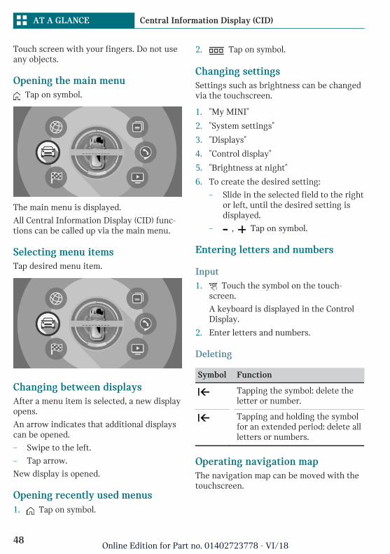
Touch screen with your fingers. Do not useany objects.
Opening the main menu Tap on symbol.
The main menu is displayed.
All Central Information Display (CID) func-tions can be called up via the main menu.
Selecting menu itemsTap desired menu item.
Changing between displaysAfter a menu item is selected, a new displayopens.
An arrow indicates that additional displayscan be opened.
– Swipe to the left.
– Tap arrow.
New display is opened.
Opening recently used menus1. Tap on symbol.
2. Tap on symbol.
Changing settingsSettings such as brightness can be changedvia the touchscreen.
1. "My MINI"
2. "System settings"
3. "Displays"
4. "Control display"
5. "Brightness at night"
6. To create the desired setting:
– Slide in the selected field to the rightor left, until the desired setting isdisplayed.
– , Tap on symbol.
Entering letters and numbers
Input1. Touch the symbol on the touch-
screen.
A keyboard is displayed in the ControlDisplay.
2. Enter letters and numbers.
Deleting
Symbol Function
Tapping the symbol: delete theletter or number.
Tapping and holding the symbolfor an extended period: delete allletters or numbers.
Operating navigation mapThe navigation map can be moved with thetouchscreen.
Seite 48
AT A GLANCE Central Information Display (CID)
48Online Edition for Part no. 01402723778 - VI/18
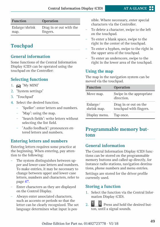
Function Operation
Enlarge/shrinkmap.
Drag in or out with thefingers.
Touchpad
General informationSome functions of the Central InformationDisplay (CID) can be operated using thetouchpad on the Controller:
Selecting functions1. "My MINI"
2. "System settings"
3. "Touchpad"
4. Select the desired function.
– "Speller": enter letters and numbers.
– "Map": using the map.
– "Search fields": write letters withoutselecting the list field.
– "Audio feedback": pronounces en-tered letters and numbers.
Entering letters and numbersEntering letters requires some practice atthe beginning. When entering, pay atten-tion to the following:
– The system distinguishes between up-per and lower-case letters and numbers.To make entries, it may be necessary tochange between upper and lower-caseletters, numbers and characters, refer topage 47.
– Enter characters as they are displayedon the Control Display.
– Always enter associated characters,such as accents or periods so that theletter can be clearly recognized. The setlanguage determines what input is pos-
sible. Where necessary, enter specialcharacters via the Controller.
– To delete a character, swipe to the lefton the touchpad.
– To enter a blank space, swipe to theright in the center of the touchpad.
– To enter a hyphen, swipe to the right inthe upper area of the touchpad.
– To enter an underscore, swipe to theright in the lower area of the touchpad.
Using the mapThe map in the navigation system can bemoved via the touchpad.
Function Operation
Move map. Swipe in the appropriatedirection.
Enlarge/shrink map.
Drag in or out on thetouchpad with fingers.
Display menu. Tap once.
Programmable memory but-tons
General informationThe Central Information Display (CID) func-tions can be stored on the programmablememory buttons and called up directly, forinstance radio stations, navigation destina-tions, phone numbers and menu entries.
Settings are stored for the driver profilecurrently used.
Storing a function1. Select the function via the Central Infor-
mation Display (CID).
2. Press and hold the desired but-ton, until a signal sounds.
Seite 49
Central Information Display (CID) AT A GLANCE
49Online Edition for Part no. 01402723778 - VI/18
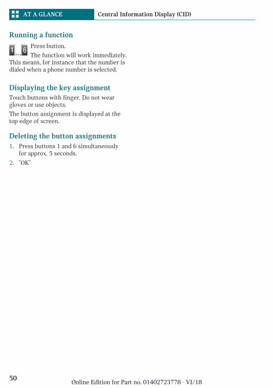
Running a functionPress button.
The function will work immediately.This means, for instance that the number isdialed when a phone number is selected.
Displaying the key assignmentTouch buttons with finger. Do not weargloves or use objects.
The button assignment is displayed at thetop edge of screen.
Deleting the button assignments1. Press buttons 1 and 6 simultaneously
for approx. 5 seconds.
2. "OK"
Seite 50
AT A GLANCE Central Information Display (CID)
50Online Edition for Part no. 01402723778 - VI/18
Voice activation system
Vehicle features and options
This chapter describes all standard, country-specific and optional features offered withthe series. It also describes features that arenot necessarily available in your vehicle,e. g., due to the selected options or countryversions. This also applies to safety-relatedfunctions and systems. When using thesefunctions and systems, the applicable lawsand regulations must be observed.
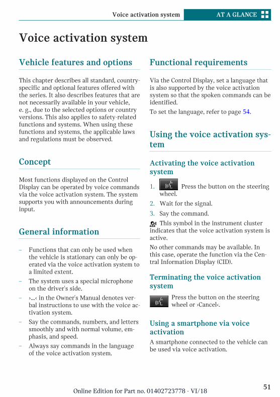
Concept
Most functions displayed on the ControlDisplay can be operated by voice commandsvia the voice activation system. The systemsupports you with announcements duringinput.
General information
– Functions that can only be used whenthe vehicle is stationary can only be op-erated via the voice activation system toa limited extent.
– The system uses a special microphoneon the driver's side.
– ›...‹ in the Owner's Manual denotes ver-bal instructions to use with the voice ac-tivation system.
– Say the commands, numbers, and letterssmoothly and with normal volume, em-phasis, and speed.
– Always say commands in the languageof the voice activation system.
Functional requirements
Via the Control Display, set a language thatis also supported by the voice activationsystem so that the spoken commands can beidentified.
To set the language, refer to page 54.
Using the voice activation sys-tem
Activating the voice activationsystem
1. Press the button on the steeringwheel.
2. Wait for the signal.
3. Say the command.
This symbol in the instrument clusterindicates that the voice activation system isactive.
No other commands may be available. Inthis case, operate the function via the Cen-tral Information Display (CID).
Terminating the voice activationsystem
Press the button on the steeringwheel or ›Cancel‹.
Using a smartphone via voiceactivationA smartphone connected to the vehicle canbe used via voice activation.
Seite 51
Voice activation system AT A GLANCE
51Online Edition for Part no. 01402723778 - VI/18
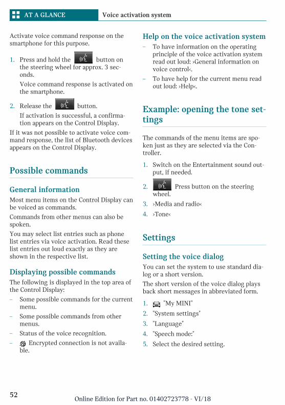
Activate voice command response on thesmartphone for this purpose.
1. Press and hold the button onthe steering wheel for approx. 3 sec-onds.
Voice command response is activated onthe smartphone.
2. Release the button.
If activation is successful, a confirma-tion appears on the Control Display.
If it was not possible to activate voice com-mand response, the list of Bluetooth devicesappears on the Control Display.
Possible commands
General informationMost menu items on the Control Display canbe voiced as commands.
Commands from other menus can also bespoken.
You may select list entries such as phonelist entries via voice activation. Read theselist entries out loud exactly as they areshown in the respective list.
Displaying possible commandsThe following is displayed in the top area ofthe Control Display:
– Some possible commands for the currentmenu.
– Some possible commands from othermenus.
– Status of the voice recognition.
– Encrypted connection is not availa-ble.
Help on the voice activation system– To have information on the operating
principle of the voice activation systemread out loud: ›General information onvoice control‹.
– To have help for the current menu readout loud: ›Help‹.
Example: opening the tone set-tings
The commands of the menu items are spo-ken just as they are selected via the Con-troller.
1. Switch on the Entertainment sound out-put, if needed.
2. Press button on the steeringwheel.
3. ›Media and radio‹
4. ›Tone‹
Settings
Setting the voice dialogYou can set the system to use standard dia-log or a short version.
The short version of the voice dialog playsback short messages in abbreviated form.
1. "My MINI"
2. "System settings"
3. "Language"
4. "Speech mode:"
5. Select the desired setting.
Seite 52
AT A GLANCE Voice activation system
52Online Edition for Part no. 01402723778 - VI/18
Activating voice recognition viathe serverThe voice recognition feature via the serverprovides a dictation function and a naturalmethod of entering destinations while im-proving the quality of voice recognition. Touse the functions, data is transmitted to aservice provider via an encrypted connec-tion and stored locally there.
1. "My MINI"
2. "System settings"
3. "Language"
4. "Server speech recognition"
Speaking during voice outputIt is possible to answer during inquiries ofthe voice activation system. The functioncan be deactivated if inquiries are often un-desirably interrupted, for instance due tobackground noise or talking.
1. "My MINI"
2. "System settings"
3. "Language"
4. "Speaking during voice output"
Setting the language
The language to be used for voice activationand system announcements can be set.
1. "My MINI"
2. "System settings"
3. "Language"
4. "Language:"
5. Select the desired language.
Adjusting the volume
Turn the volume button during the spokeninstructions until the desired volume is set.
– The volume remains constant even if thevolume of other audio sources ischanged.
– The volume is stored for the profile cur-rently used.
Information on EmergencyRequests
Do not use the voice activation system toinitiate an Emergency Request. In stressfulsituations, the voice and vocal pitch canchange. This can unnecessarily delay the es-tablishment of a phone connection.
Instead, use the SOS button, refer topage 294, close to the interior mirror.
Environmental conditions
– Keep the doors, windows, andconvertible top closed to prevent noiseinterference.
– Avoid making other noise in the vehiclewhile speaking.
Seite 53
Voice activation system AT A GLANCE
53Online Edition for Part no. 01402723778 - VI/18
General settings
Vehicle features and options
This chapter describes all standard, country-specific and optional features offered withthe series. It also describes features that arenot necessarily available in your vehicle,e. g., due to the selected options or countryversions. This also applies to safety-relatedfunctions and systems. When using thesefunctions and systems, the applicable lawsand regulations must be observed.
Language
Setting the languageVia the Central Information Display (CID):
1. "My MINI"
2. "System settings"
3. "Language"
4. "Language:"
5. Select the desired setting.
The setting is stored for the driver profilecurrently used.
Setting the voice dialogVoice dialog for the voice activation system,refer to page 52.
Time
Setting the time zoneVia the Central Information Display (CID):
1. "My MINI"
2. "System settings"
3. "Date and time"
4. "Time zone:"
5. Select the desired setting.
The setting is stored for the driver profilecurrently used.
Setting the timeVia the Central Information Display (CID):
1. "My MINI"
2. "System settings"
3. "Date and time"
4. "Time:"
5. Turn the Controller until the desiredhours are displayed.
6. Press the Controller.
7. Turn the Controller until the desired mi-nutes are displayed.
8. Press the Controller.
Setting the time formatVia the Central Information Display (CID):
1. "My MINI"
2. "System settings"
3. "Date and time"
4. "Time format:"
5. Select the desired setting.
The setting is stored for the driver profilecurrently used.
Seite 54
AT A GLANCE General settings
54Online Edition for Part no. 01402723778 - VI/18
Date
Setting the dateVia the Central Information Display (CID):
1. "My MINI"
2. "System settings"
3. "Date and time"
4. "Date:"
5. Turn the Controller until the desired dayis displayed.
6. Press the Controller.
7. Make the settings for the month andyear.
Setting the date formatVia the Central Information Display (CID):
1. "My MINI"
2. "System settings"
3. "Date and time"
4. "Date format:"
5. Select the desired setting.
The setting is stored for the driver profilecurrently used.
Setting the units of measure-ment
You can set the units of measurement forsome values, for example, fuel consumption,distances and temperature.
Via the Central Information Display (CID):
1. "My MINI"
2. "System settings"
3. "Units"
4. Select the desired menu item.
5. Select the desired setting.
The setting is stored for the driver profilecurrently used.
Activating/deactivating thedisplay of the current vehicleposition
ConceptIf vehicle location has been activated, thecurrent vehicle position can be displayed inthe MINI Connected app.
Activating/deactivatingVia the Central Information Display (CID):
1. "My MINI"
2. "Vehicle settings"
3. "Vehicle tracking"
4. "Vehicle tracking"
5. Select the desired setting.
Activating/deactivatingpopup windows
For some functions, popup windows are dis-played automatically on the Control Display.Some of these popup windows can be acti-vated or deactivated.
Via the Central Information Display (CID):
1. "My MINI"
2. "System settings"
3. "Pop-ups"
4. Select the desired setting.
The setting is stored for the driver profilecurrently used.
Seite 55
General settings AT A GLANCE
55Online Edition for Part no. 01402723778 - VI/18
Control Display
BrightnessVia the Central Information Display (CID):
1. "My MINI"
2. "System settings"
3. "Displays"
4. "Control display"
5. "Brightness at night"
6. Turn the Controller until the desiredbrightness is set.
7. Press the Controller.
The setting is stored for the driver profilecurrently used.
Depending on the light conditions, thebrightness settings may not be clearly visi-ble.
ScreensaverIf no entries are made via the Central Infor-mation Display (CID), a screensaver can bedisplayed after an adjustable time.
Via the Central Information Display (CID):
1. "My MINI"
2. "System settings"
3. "Displays"
4. "Control display"
5. "Screensaver"
6. Select the desired setting.
The setting is stored for the driver profilecurrently used.
Messages
ConceptThe menu centrally displays all messages ar-riving in the vehicle in list form.
General informationThe following messages can be displayed:
– Traffic messages.
– Check Control messages.
– Communication messages, for examplee-mails, SMS text messages or remind-ers.
– Service requirements messages.
Messages are additionally displayed in thestatus field.
Retrieving messagesVia the Central Information Display (CID):
1. "Notifications"
2. Select the desired message.
The respective menu is opened, where themessage is displayed.
Deleting messagesAll messages, except Check Control mes-sages, can be deleted from the list. CheckControl messages are displayed as long asthey are relevant.
Via the Central Information Display (CID):
1. "Notifications"
2. Select the desired message.
3. Press button.
4. "Delete this notification" or "Delete allnotifications"
SettingsThe following settings can be adjusted:
Seite 56
AT A GLANCE General settings
56Online Edition for Part no. 01402723778 - VI/18
– Select the applications, from which mes-sages will be permitted.
– Sort the messages according to date orpriority.
Via the Central Information Display (CID):
1. "My MINI"
2. "System settings"
3. "Notifications"
4. Select the desired setting.
Data protection
Data transfer
ConceptThe vehicle offers various functions whichrequire data to be transferred to MINI or aservice provider. The data transfer can bedeactivated for some functions.
General informationWith data transfer deactivated, the respec-tive function cannot be used.
Only make these settings while stationary.
Activating/deactivating the datatransferFollow the instructions on the Control Dis-play.
Via the Central Information Display (CID):
1. Switch on the ignition.
2. "My MINI"
3. "System settings"
4. "Data privacy"
5. Select the desired setting.
Deleting personal data in thevehicle
ConceptDepending on the usage, the vehicle storespersonal data, such as stored radio stations.This personal data can be permanently de-leted via the Central Information Display(CID).
General informationDepending on the vehicle equipment, thefollowing data is deleted:
– Driver profile settings.
– Stored radio stations.
– Stored programmable memory buttons.
– Travel and Onboard Computer informa-tion.
– Music collection.
– Navigation, for instance stored destina-tions.
– Phone book.
– Office data, for instance voice notes.
– Login accounts.
Altogether, the deletion of the data can takeup to 15 minutes.
Functional requirementData can only be deleted while stationary.
Deleting dataHeed and follow the instructions on theControl Display.
Via the Central Information Display (CID):
1. Switch on the ignition.
2. "My MINI"
3. "System settings"
4. "Data privacy"
5. "Delete personal data"
Seite 57
General settings AT A GLANCE
57Online Edition for Part no. 01402723778 - VI/18
6. "Delete personal data"
7. "OK"
8. Exit and lock the vehicle.
After 15 minutes, the deletion process iscompleted.
If not all of the data was deleted, repeat thedeletion.
Canceling deletionStart the engine to cancel deletion of thedata.
Connections
ConceptVarious connection types are available forusing mobile devices in the vehicle. Theconnection type to select depends on themobile device and the desired function.
General informationThe following overview shows possiblefunctions and the suitable connection typesfor them. The scope of functions depends onthe mobile device.
Function Connec-tion type
Making calls via the hands-free system.
Using phone functions viathe Central Information Dis-play (CID).
Using the smartphone Of-fice functions.
Bluetooth.
Playing music from thesmartphone or the audioplayer.
Bluetoothor USB.
Function Connec-tion type
Using compatible apps viathe Central Information Dis-play (CID).
Bluetoothor USB.
USB storage device:
Exporting and importingdriver profiles.
Performing software up-dates.
Playing music.
USB.
Playing videos from thesmartphone or the USB stor-age device.
USB.
Using Apple CarPlay appsvia the Central InformationDisplay (CID) and voice op-eration.
Bluetoothand WiFi.
The following connection types require one-time pairing with the vehicle:
– Bluetooth.
– Apple CarPlay
Paired devices are automatically recognizedlater on and connected to the vehicle.
Safety information
WARNING
Operating the integrated information sys-tems and communication devices whiledriving can distract from traffic. It is pos-sible to lose control of the vehicle. There isa risk of an accident. Only use the systemsor devices when the traffic situation al-lows. As warranted, stop and use the sys-tems and devices while the vehicle is sta-tionary.
Seite 58
AT A GLANCE General settings
58Online Edition for Part no. 01402723778 - VI/18
Compatible devices
General informationInformation on mobile devices compatiblewith the vehicle can be found at www.mini-usa.com/bluetooth.
Malfunctions may occur with devices notlisted or deviating software versions.
Displaying the vehicle identificationnumber and software part numberWhen looking for compatible devices, youmay have to state the vehicle identificationnumber and the software part number.These numbers can be displayed in the ve-hicle.
Via the Central Information Display (CID):
1. "My MINI"
2. "System settings"
3. "Mobile devices"
4. "Settings"
5. "Bluetooth® info"
6. "System information"
A software update, refer to page 64, canbe performed, if needed.
Bluetooth connection
Functional requirements– Compatible device, refer to page 59,
with Bluetooth interface.
– The remote control is in the vehicle.
– The device is ready for operation.
– Bluetooth is activated on the device andin the vehicle, refer to page 59.
– Bluetooth pre-settings, such as visibil-ity, may be required on the device; referto the owner's manual of the device.
Switching on BluetoothVia the Central Information Display (CID):
1. "My MINI"
2. "System settings"
3. "Mobile devices"
4. "Settings"
5. "Bluetooth®"
Activating/deactivating telephonefunctionsTo use all supported functions of a mobilephone, the following functions must be acti-vated prior to pairing.
Via the Central Information Display (CID):
1. "My MINI"
2. "System settings"
3. "Mobile devices"
4. "Settings"
5. Select desired setting:
– "Office"
Activate function to transmit shortmessages, e-mails, calendars, tasks,notes, and reminders to the vehicle.Costs can be incurred by transmit-ting all data to the vehicle.
– "Contact images"
Activate function to show the con-tact pictures.
6. Move the Controller to the left.
Pairing the mobile device with thevehicleVia the Central Information Display (CID):
1. "My MINI"
2. "System settings"
3. "Mobile devices"
4. "Connect new device"
Seite 59
General settings AT A GLANCE
59Online Edition for Part no. 01402723778 - VI/18
5. Select the functions for which the de-vice will be used:
– "Telephone"
– "Bluetooth® audio"
– "Apps"
– "Apple CarPlay"
The Bluetooth name of the vehicle isdisplayed on the Control Display.
6. Search for Bluetooth devices in the vi-cinity of the mobile device.
The Bluetooth name of the vehicle ap-pears on the mobile device display.
Select the Bluetooth name of the vehi-cle.
7. Depending on the mobile device, a con-trol number is displayed or the controlnumber must be entered.
– Compare the control number dis-played on the Control Display withthe control number on the display ofthe device.
Confirm the control number on thedevice and on the Control Display.
– Enter and confirm the same controlnumber on the device and via theCentral Information Display (CID).
The device is connected and displayedin the device list.
If connection was not successful: Fre-quently Asked Questions, refer to page 60.
Frequently asked questionsAll requirements are met and all requiredsteps were completed in the specified order.Despite that, the mobile device does notfunction as expected.
In this case, the following explanations canhelp:
Why could the mobile phone not be pairedor connected?
– There are too many Bluetooth devicesconnected to the mobile phone or vehi-cle.
In the vehicle, delete Bluetooth connec-tions with other devices.
Delete all known Bluetooth connectionsfrom the device list on the mobile phoneand start a new device search.
– The mobile phone is in power-save modeor has only a limited remaining batterylife.
Charge mobile phone.
Why does the mobile phone no longer re-act?
– The applications on the mobile phone donot function anymore.
Switch the mobile phone off and onagain.
– Possibly too high or too low ambienttemperatures for mobile phone opera-tion.
Do not subject the mobile phone to ex-treme ambient temperatures.
Why can phone functions not be used viathe Central Information Display (CID)?
– The mobile phone may not be properlyconfigured, for instance as Bluetooth au-dio device.
Connect the mobile phone with the tele-phone or additional phone function.
Why are no or not all phone book entriesdisplayed or why are they incomplete?
– Transmission of the phone book entriesis not yet complete.
– It is possible that only the phone bookentries of the mobile phone or the SIMcard are transmitted.
– It may not be possible to display phonebook entries with special characters.
– It may not be possible to transmit con-tacts from social networks.
Seite 60
AT A GLANCE General settings
60Online Edition for Part no. 01402723778 - VI/18
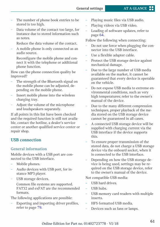
– The number of phone book entries to bestored is too high.
– Data volume of the contact too large, forinstance due to stored information suchas notes.
Reduce the data volume of the contact.
– A mobile phone is only connected as anaudio source.
Reconfigure the mobile phone and con-nect it with the telephone or additionalphone function.
How can the phone connection quality beimproved?
– The strength of the Bluetooth signal onthe mobile phone can be adjusted, de-pending on the mobile phone.
– Insert mobile phone into the wirelesscharging tray.
– Adjust the volume of the microphoneand loudspeakers separately.
If all points in this list have been checkedand the required function is still not availa-ble, contact the hotline, a dealer’s servicecenter or another qualified service center orrepair shop.
USB connection
General informationMobile devices with a USB port are con-nected to the USB interface.
– Mobile phones.
– Audio devices with USB port, for in-stance MP3 player.
– USB storage devices.
Common file systems are supported.FAT32 and exFAT are the recommendedformats.
The following applications are possible:
– Exporting and importing driver profiles,refer to page 79.
– Playing music files via USB audio.
– Playing videos via USB video.
– Loading of software updates, refer topage 64.
Follow the following when connecting:
– Do not use force when plugging the con-nector into the USB interface.
– Use a flexible adapter cable.
– Protect the USB storage device againstmechanical damage.
– Due to the large number of USB mediaavailable on the market, it cannot beguaranteed that every device is operableon the vehicle.
– Do not expose USB media to extreme en-vironmental conditions, such as veryhigh temperatures; refer to the owner'smanual of the device.
– Due to the many different compressiontechniques, proper playback of the me-dia stored on the USB storage devicecannot be guaranteed in all cases.
– A connected USB storage device will besupplied with charging current via theUSB interface if the device supportsthis.
– To ensure proper transmission of thestored data, do not charge a USB storagedevice via the onboard socket, when itis connected to the USB interface.
– Depending on how the USB storage de-vice is being used, settings may be re-quired on the USB storage device, referto the owner's manual of the device.
Not compatible USB media:
– USB hard drives.
– USB hubs.
– USB memory card readers with multipleinserts.
– HFS-formatted USB media.
– Devices such as fans or lamps.
Seite 61
General settings AT A GLANCE
61Online Edition for Part no. 01402723778 - VI/18
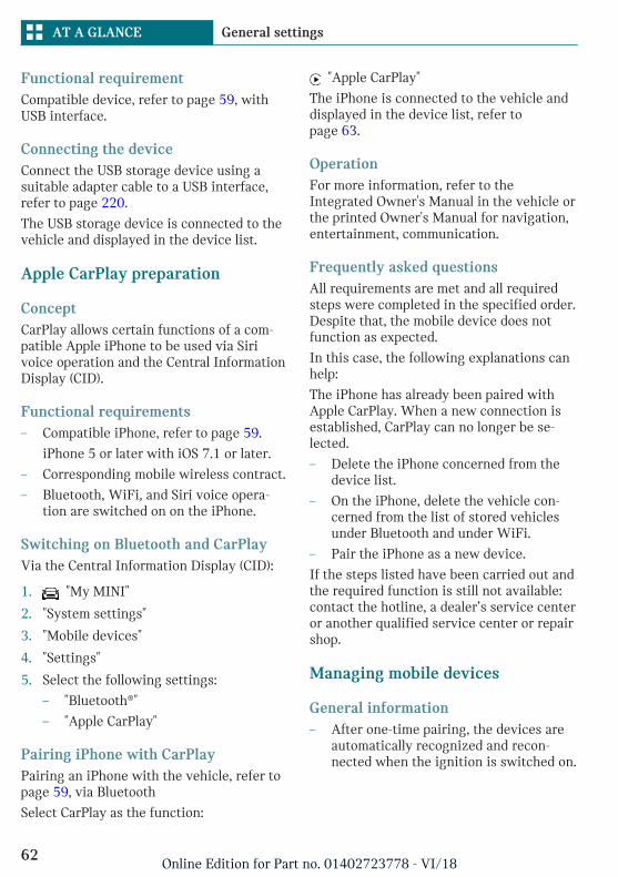
Functional requirementCompatible device, refer to page 59, withUSB interface.
Connecting the deviceConnect the USB storage device using asuitable adapter cable to a USB interface,refer to page 220.
The USB storage device is connected to thevehicle and displayed in the device list.
Apple CarPlay preparation
ConceptCarPlay allows certain functions of a com-patible Apple iPhone to be used via Sirivoice operation and the Central InformationDisplay (CID).
Functional requirements– Compatible iPhone, refer to page 59.
iPhone 5 or later with iOS 7.1 or later.
– Corresponding mobile wireless contract.
– Bluetooth, WiFi, and Siri voice opera-tion are switched on on the iPhone.
Switching on Bluetooth and CarPlayVia the Central Information Display (CID):
1. "My MINI"
2. "System settings"
3. "Mobile devices"
4. "Settings"
5. Select the following settings:
– "Bluetooth®"
– "Apple CarPlay"
Pairing iPhone with CarPlayPairing an iPhone with the vehicle, refer topage 59, via Bluetooth
Select CarPlay as the function:
"Apple CarPlay"
The iPhone is connected to the vehicle anddisplayed in the device list, refer topage 63.
OperationFor more information, refer to theIntegrated Owner's Manual in the vehicle orthe printed Owner's Manual for navigation,entertainment, communication.
Frequently asked questionsAll requirements are met and all requiredsteps were completed in the specified order.Despite that, the mobile device does notfunction as expected.
In this case, the following explanations canhelp:
The iPhone has already been paired withApple CarPlay. When a new connection isestablished, CarPlay can no longer be se-lected.
– Delete the iPhone concerned from thedevice list.
– On the iPhone, delete the vehicle con-cerned from the list of stored vehiclesunder Bluetooth and under WiFi.
– Pair the iPhone as a new device.
If the steps listed have been carried out andthe required function is still not available:contact the hotline, a dealer’s service centeror another qualified service center or repairshop.
Managing mobile devices
General information– After one-time pairing, the devices are
automatically recognized and recon-nected when the ignition is switched on.
Seite 62
AT A GLANCE General settings
62Online Edition for Part no. 01402723778 - VI/18
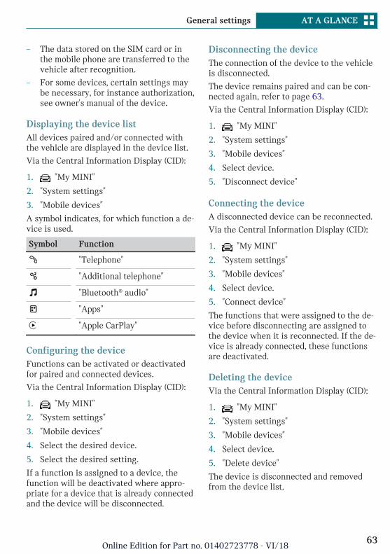
– The data stored on the SIM card or inthe mobile phone are transferred to thevehicle after recognition.
– For some devices, certain settings maybe necessary, for instance authorization,see owner's manual of the device.
Displaying the device listAll devices paired and/or connected withthe vehicle are displayed in the device list.
Via the Central Information Display (CID):
1. "My MINI"
2. "System settings"
3. "Mobile devices"
A symbol indicates, for which function a de-vice is used.
Symbol Function
"Telephone"
"Additional telephone"
"Bluetooth® audio"
"Apps"
"Apple CarPlay"
Configuring the deviceFunctions can be activated or deactivatedfor paired and connected devices.
Via the Central Information Display (CID):
1. "My MINI"
2. "System settings"
3. "Mobile devices"
4. Select the desired device.
5. Select the desired setting.
If a function is assigned to a device, thefunction will be deactivated where appro-priate for a device that is already connectedand the device will be disconnected.
Disconnecting the deviceThe connection of the device to the vehicleis disconnected.
The device remains paired and can be con-nected again, refer to page 63.
Via the Central Information Display (CID):
1. "My MINI"
2. "System settings"
3. "Mobile devices"
4. Select device.
5. "Disconnect device"
Connecting the deviceA disconnected device can be reconnected.
Via the Central Information Display (CID):
1. "My MINI"
2. "System settings"
3. "Mobile devices"
4. Select device.
5. "Connect device"
The functions that were assigned to the de-vice before disconnecting are assigned tothe device when it is reconnected. If the de-vice is already connected, these functionsare deactivated.
Deleting the deviceVia the Central Information Display (CID):
1. "My MINI"
2. "System settings"
3. "Mobile devices"
4. Select device.
5. "Delete device"
The device is disconnected and removedfrom the device list.
Seite 63
General settings AT A GLANCE
63Online Edition for Part no. 01402723778 - VI/18
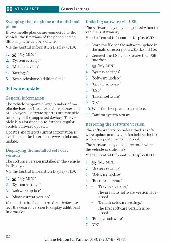
Swapping the telephone and additionalphoneIf two mobile phones are connected to thevehicle, the functions of the phone and ad-ditional phone can be switched.
Via the Central Information Display (CID):
1. "My MINI"
2. "System settings"
3. "Mobile devices"
4. "Settings"
5. "Swap telephone/additional tel."
Software update
General informationThe vehicle supports a large number of mo-bile devices, for instance mobile phones andMP3 players. Software updates are availablefor many of the supported devices. The ve-hicle is maintained up-to-date via regularvehicle software updates.
Updates and related current information isavailable on the Internet at www.mini.com/update.
Displaying the installed softwareversionThe software version installed in the vehicleis displayed.
Via the Central Information Display (CID):
1. "My MINI"
2. "System settings"
3. "Software update"
4. "Show current version"
If an update has been carried out before, se-lect the desired version to display additionalinformation.
Updating software via USBThe software may only be updated when thevehicle is stationary.
Via the Central Information Display (CID):
1. Store the file for the software update inthe main directory of a USB flash drive.
2. Connect the USB data storage to a USBinterface.
3. "My MINI"
4. "System settings"
5. "Software update"
6. "Update software"
7. "USB"
8. "Install software"
9. "OK"
10. Wait for the update to complete.
11. Confirm system restart.
Restoring the software versionThe software version before the last soft-ware update and the version before the firstsoftware update can be restored.
The software may only be restored whenthe vehicle is stationary.
Via the Central Information Display (CID):
1. "My MINI"
2. "System settings"
3. "Software update"
4. "Restore software"
5. – "Previous version"
The previous software version is re-stored.
– "Default software settings"
The first software version is re-stored.
6. "Remove software"
7. "OK"
Seite 64
AT A GLANCE General settings
64Online Edition for Part no. 01402723778 - VI/18

8. Wait for restore.
9. Confirm system restart.
Seite 65
General settings AT A GLANCE
65Online Edition for Part no. 01402723778 - VI/18
Owner's Manual media
Vehicle features and options
This chapter describes all standard, country-specific and optional features offered withthe series. It also describes features that arenot necessarily available in your vehicle,e. g., due to the selected options or countryversions. This also applies to safety-relatedfunctions and systems. When using thesefunctions and systems, the applicable lawsand regulations must be observed.
General information
You can use the following media formats tocall up the content in the Owner's Manual:
– Printed Owner's Manual, refer topage 66.
– Integrated Owner's Manual in the vehi-cle, refer to page 66.
Printed Owner's Manual
ConceptThe printed Owner's Manual describes allstandard, country-specific, and optional fea-tures offered with the series.
General informationThe Owner's Manual for Navigation, Enter-tainment, and Communication can be ob-tained as printed book from the service cen-ter.
Supplementary Owner's ManualsAlso follow the instructions of the Supple-mentary Owner's Manuals, which are in-cluded in addition to the onboard literature.
Integrated Owner's Manual inthe vehicle
ConceptThe Integrated Owner's Manual specificallydescribes features and functions found inthe vehicle. The Integrated Owner's Manualcan be displayed on the Control Display.
Selecting the Owner's Manual
1. Press button.
2. "My MINI"
3. "Owner's Manual"
4. Select the required method of accessingthe contents.
Scrolling through the owner'smanualTurn the Controller, until the next or previ-ous contents are displayed.
Context help
General informationThe section of the Owner's Manual relatingto the function that is currently selectedcan be displayed directly.
Seite 66
AT A GLANCE Owner's Manual media
66Online Edition for Part no. 01402723778 - VI/18
Opening via Central InformationDisplay (CID)Change directly to the Options menu fromthe function on the Control Display:
1. Press button.
2. "Owner's Manual"
Opening when a Check Controlmessage is displayedDirectly from the Check Control message onthe Control Display:
"Owner's Manual"
Changing between a function and theOwner's ManualTo switch from a function, for instanceradio, to the Owner's Manual on the ControlDisplay and to alternate between the twodisplays:
1. Press the button.
2. "Owner's Manual"
3. Select the desired page in the Owner'sManual.
4. Press the button again to return tolast displayed function.
5. Press the button to return to thepage of the Owner's Manual displayedlast.
To alternate continuously between the lastdisplayed function and the last displayedpage of the Owner's Manual, repeat steps 4& 5. Opens a new display every time.
Programmable memory buttons
General informationThe Owner's Manual can be stored on theprogrammable memory buttons and calledup directly.
Storing1. Select the desired entry point via the
Central Information Display (CID):
– "Quick reference"
– "Search by pictures"
– "Keyword search"
– "Animations"
2. Press and hold the desired but-ton, until a signal sounds.
Executing
Press button.
The Owner's Manual is displayedimmediately.
Seite 67
Owner's Manual media AT A GLANCE
67Online Edition for Part no. 01402723778 - VI/18

68
Online Edition for Part no. 01402723778 - VI/18
CONTROLS
Opening and closing ................................................................................ 70Seats, mirrors, and steering wheel ..................................................... 95Transporting children safely .............................................................. 105Driving ...................................................................................................... 109Displays .................................................................................................... 132Lights ........................................................................................................ 152Safety ......................................................................................................... 158Driving stability control systems ..................................................... 180Driving comfort ...................................................................................... 185Climate control ....................................................................................... 205Interior equipment ................................................................................ 214Storage compartments ......................................................................... 221Cargo area ................................................................................................ 224
69Online Edition for Part no. 01402723778 - VI/18
Opening and closing
Vehicle features and options
This chapter describes all standard, country-specific and optional features offered withthe series. It also describes features that arenot necessarily available in your vehicle,e. g., due to the selected options or countryversions. This also applies to safety-relatedfunctions and systems. When using thesefunctions and systems, the applicable lawsand regulations must be observed.
Remote control
General informationThe vehicle is supplied with two remotecontrols with integrated key.
Each remote control contains a replaceablebattery. Replacing the battery, refer topage 73.
You may set the button functions, depend-ing on the vehicle equipment and countryversion. Settings, refer to page 82.
The vehicle stores personal settings for ev-ery remote control. Driver profile, refer topage 79.
The remote controls hold information aboutrequired maintenance. Service data in theremote control, refer to page 280.
To prevent possible locking in of the remotecontrol, take the remote control with youwhen exiting the vehicle.
Safety information
WARNING
People or animals in the vehicle can lockthe doors from the inside and lock them-selves in. In this case, the vehicle cannotbe opened from the outside. There is a riskof injury. Take the remote control withyou so that the vehicle can be opened fromthe outside.
WARNING
Unlocking from the inside is only possiblewith special knowledge.
Persons who spend a lengthy time in thevehicle while being exposed to extremetemperatures are at risk of injury or death.Do not lock the vehicle from the outsidewhen there are people in it.
WARNING
Unattended children or animals can causethe vehicle to move and endanger them-selves and traffic, for instance due to thefollowing actions:
– Pressing the Start/Stop button.
– Releasing the parking brake.
– Opening and closing the doors orwindows.
– Engaging selector lever position N.
– Using vehicle equipment.
There is a risk of accidents or injuries. Donot leave children or animals unattendedin the vehicle. Take the remote controlwith you when exiting and lock the vehi-cle.
Seite 70
CONTROLS Opening and closing
70Online Edition for Part no. 01402723778 - VI/18
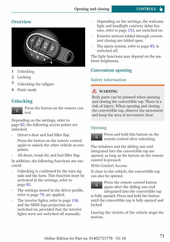
Overview
1 Unlocking
2 Locking
3 Unlocking the tailgate
4 Panic mode
UnlockingPress the button on the remote con-trol.
Depending on the settings, refer topage 82, the following access points areunlocked.
– Driver's door and fuel filler flap.
Press the button on the remote controlagain to unlock the other vehicle accesspoints.
– All doors, trunk lid, and fuel filler flap.
In addition, the following functions are exe-cuted:
– Unlocking is confirmed by the turn sig-nals and the horn. This function must beactivated in the settings, refer topage 82.
– The settings stored in the driver profile,refer to page 79, are applied.
– The interior lights, refer to page 156,and the MINI logo projection areswitched on, provided that the interiorlights were not switched off manually.
– Depending on the settings, the welcomelight and headlight courtesy delay fea-ture, refer to page 153, are switched on.
– Exterior mirrors folded through conven-ient closing are folded open.
– The alarm system, refer to page 83, isswitched off.
The light functions may depend on the am-bient brightness.
Convenient opening
Safety information
WARNING
Body parts can be jammed when openingand closing the convertible top. There is arisk of injury. When opening and closingthe convertible top, observe the movementand keep the area of movement clear.
Opening
Press and hold this button on theremote control after unlocking.
The windows and the sliding sun roofintegrated into the convertible top areopened, as long as the button on the remotecontrol is pressed.
With Comfort Access:
If close to the vehicle, the convertible topcan also be opened.
Press the remote control buttonagain after the sliding sun roofintegrated into the convertible top
is fully opened. Press and hold the buttonuntil the convertible top is fully opened andlocked.
Leaving the vicinity of the vehicle stops themotion.
Seite 71
Opening and closing CONTROLS
71Online Edition for Part no. 01402723778 - VI/18
Locking1. Close the driver's door.
2. Press button on the remote con-trol.
The following functions are executed:
– All doors, the tailgate, and the fuel fillerflap are locked.
– Locking is confirmed by the turn signalsand the horn. This function must be ac-tivated in the settings, refer topage 82.
– The alarm system, refer to page 83, isswitched on.
If the engine or ignition is still switched onwhen you lock the vehicle, the vehicle hornhonks twice. In this case, the engine or ig-nition must be switched off by means of theStart/Stop button.
With Comfort Access: convenientclosing
Safety information
WARNING
With convenient closing, body parts canbe jammed. There is a risk of injury. Makesure that the area of movement of thedoors is clear during convenient closing.
WARNING
Body parts can be jammed when openingand closing the convertible top. There is arisk of injury. When opening and closingthe convertible top, observe the movementand keep the area of movement clear.
Closing
Press and hold the button on the re-mote control in the area close to thevehicle, until the closing operation
is completed.
The windows and convertible top close.
Releasing the button stops the closing pro-cedure. Leaving the vicinity of the vehiclestops the motion of the convertible top.
Press button in the vicinity of the vehicleagain until the convertible top operation iscompleted.
Switch on interior lights andcourtesy light
Press button on the remote controlwith the vehicle locked.
The MINI logo projection is also switchedon.
These functions are not available if the inte-rior lights were switched off manually.
The light functions may depend on the am-bient brightness.
After locking, wait 10 seconds before press-ing the button again.
Tailgate
General informationTo avoid locking it in the vehicle, do notplace the remote control in the cargo area.
Depending on the vehicle equipment andcountry version, it is possible to specifywhether the tailgate can be unlocked withthe remote control and how the vehicledoors will respond to this. Adjust the set-tings, refer to page 82.
Seite 72
CONTROLS Opening and closing
72Online Edition for Part no. 01402723778 - VI/18
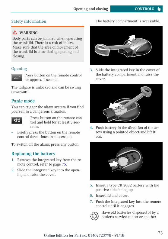
Safety information
WARNING
Body parts can be jammed when operatingthe trunk lid. There is a risk of injury.Make sure that the area of movement ofthe trunk lid is clear during opening andclosing.
Opening
Press button on the remote controlfor approx. 1 second.
The tailgate is unlocked and can be swungdownward.
Panic modeYou can trigger the alarm system if you findyourself in a dangerous situation.
– Press button on the remote con-trol and hold for at least 3 sec-onds.
– Briefly press the button on the remotecontrol three times in succession.
To switch off the alarm: press any button.
Replacing the battery1. Remove the integrated key from the re-
mote control, refer to page 75.
2. Slide the integrated key into the open-ing and raise the cover.
The battery compartment is accessible.
3. Slide the integrated key in the cover ofthe battery compartment and raise thecover.
4. Push battery in the direction of the ar-row using a pointed object and lift itout.
5. Insert a type CR 2032 battery with thepositive side facing up.
6. Insert lid and cover.
7. Push the integrated key into the remotecontrol until it engages.
Have old batteries disposed of by adealer’s service center or another
Seite 73
Opening and closing CONTROLS
73Online Edition for Part no. 01402723778 - VI/18
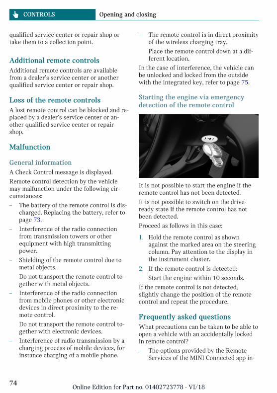
qualified service center or repair shop ortake them to a collection point.
Additional remote controlsAdditional remote controls are availablefrom a dealer’s service center or anotherqualified service center or repair shop.
Loss of the remote controlsA lost remote control can be blocked and re-placed by a dealer’s service center or an-other qualified service center or repairshop.
Malfunction
General informationA Check Control message is displayed.
Remote control detection by the vehiclemay malfunction under the following cir-cumstances:
– The battery of the remote control is dis-charged. Replacing the battery, refer topage 73.
– Interference of the radio connectionfrom transmission towers or otherequipment with high transmittingpower.
– Shielding of the remote control due tometal objects.
Do not transport the remote control to-gether with metal objects.
– Interference of the radio connectionfrom mobile phones or other electronicdevices in direct proximity to the re-mote control.
Do not transport the remote control to-gether with electronic devices.
– Interference of radio transmission by acharging process of mobile devices, forinstance charging of a mobile phone.
– The remote control is in direct proximityof the wireless charging tray.
Place the remote control down at a dif-ferent location.
In the case of interference, the vehicle canbe unlocked and locked from the outsidewith the integrated key, refer to page 75.
Starting the engine via emergencydetection of the remote control
It is not possible to start the engine if theremote control has not been detected.
It is not possible to switch on the drive-ready state if the remote control has notbeen detected.
Proceed as follows in this case:
1. Hold the remote control as shownagainst the marked area on the steeringcolumn. Pay attention to the display inthe instrument cluster.
2. If the remote control is detected:
Start the engine within 10 seconds.
If the remote control is not detected,slightly change the position of the remotecontrol and repeat the procedure.
Frequently asked questionsWhat precautions can be taken to be able toopen a vehicle with an accidentally lockedin remote control?
– The options provided by the RemoteServices of the MINI Connected app in-
Seite 74
CONTROLS Opening and closing
74Online Edition for Part no. 01402723778 - VI/18
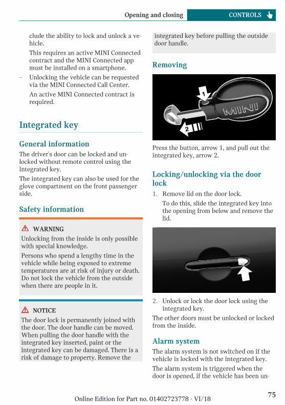
clude the ability to lock and unlock a ve-hicle.
This requires an active MINI Connectedcontract and the MINI Connected appmust be installed on a smartphone.
– Unlocking the vehicle can be requestedvia the MINI Connected Call Center.
An active MINI Connected contract isrequired.
Integrated key
General informationThe driver's door can be locked and un-locked without remote control using theintegrated key.
The integrated key can also be used for theglove compartment on the front passengerside.
Safety information
WARNING
Unlocking from the inside is only possiblewith special knowledge.
Persons who spend a lengthy time in thevehicle while being exposed to extremetemperatures are at risk of injury or death.Do not lock the vehicle from the outsidewhen there are people in it.
NOTICE
The door lock is permanently joined withthe door. The door handle can be moved.When pulling the door handle with theintegrated key inserted, paint or theintegrated key can be damaged. There is arisk of damage to property. Remove the
integrated key before pulling the outsidedoor handle.
Removing
Press the button, arrow 1, and pull out theintegrated key, arrow 2.
Locking/unlocking via the doorlock1. Remove lid on the door lock.
To do this, slide the integrated key intothe opening from below and remove thelid.
2. Unlock or lock the door lock using theintegrated key.
The other doors must be unlocked or lockedfrom the inside.
Alarm systemThe alarm system is not switched on if thevehicle is locked with the integrated key.
The alarm system is triggered when thedoor is opened, if the vehicle has been un-
Seite 75
Opening and closing CONTROLS
75Online Edition for Part no. 01402723778 - VI/18
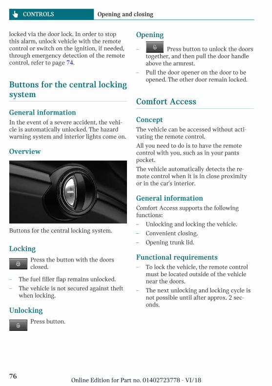
locked via the door lock. In order to stopthis alarm, unlock vehicle with the remotecontrol or switch on the ignition, if needed,through emergency detection of the remotecontrol, refer to page 74.
Buttons for the central lockingsystem
General informationIn the event of a severe accident, the vehi-cle is automatically unlocked. The hazardwarning system and interior lights come on.
Overview
Buttons for the central locking system.
LockingPress the button with the doorsclosed.
– The fuel filler flap remains unlocked.
– The vehicle is not secured against theftwhen locking.
UnlockingPress button.
Opening
– Press button to unlock the doorstogether, and then pull the door handleabove the armrest.
– Pull the door opener on the door to beopened. The other door remain locked.
Comfort Access
ConceptThe vehicle can be accessed without acti-vating the remote control.
All you need to do is to have the remotecontrol with you, such as in your pantspocket.
The vehicle automatically detects the re-mote control when it is in close proximityor in the car's interior.
General informationComfort Access supports the followingfunctions:
– Unlocking and locking the vehicle.
– Convenient closing.
– Opening trunk lid.
Functional requirements– To lock the vehicle, the remote control
must be located outside of the vehiclenear the doors.
– The next unlocking and locking cycle isnot possible until after approx. 2 sec-onds.
Seite 76
CONTROLS Opening and closing
76Online Edition for Part no. 01402723778 - VI/18
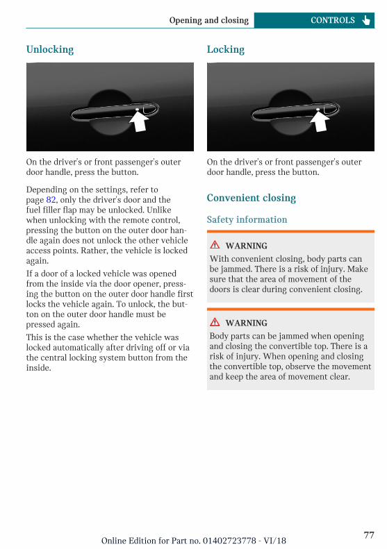
Unlocking
On the driver's or front passenger's outerdoor handle, press the button.
Depending on the settings, refer topage 82, only the driver's door and thefuel filler flap may be unlocked. Unlikewhen unlocking with the remote control,pressing the button on the outer door han-dle again does not unlock the other vehicleaccess points. Rather, the vehicle is lockedagain.
If a door of a locked vehicle was openedfrom the inside via the door opener, press-ing the button on the outer door handle firstlocks the vehicle again. To unlock, the but-ton on the outer door handle must bepressed again.
This is the case whether the vehicle waslocked automatically after driving off or viathe central locking system button from theinside.
Locking
On the driver's or front passenger's outerdoor handle, press the button.
Convenient closing
Safety information
WARNING
With convenient closing, body parts canbe jammed. There is a risk of injury. Makesure that the area of movement of thedoors is clear during convenient closing.
WARNING
Body parts can be jammed when openingand closing the convertible top. There is arisk of injury. When opening and closingthe convertible top, observe the movementand keep the area of movement clear.
Seite 77
Opening and closing CONTROLS
77Online Edition for Part no. 01402723778 - VI/18
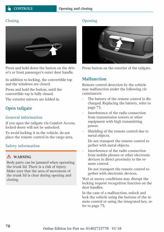
Closing
Press and hold down the button on the driv-er's or front passenger's outer door handle.
In addition to locking, the convertible topand the windows are closed.
Press and hold the button, until theconvertible top is fully closed.
The exterior mirrors are folded in.
Open tailgate
General informationIf you open the tailgate via Comfort Access,locked doors will not be unlocked.
To avoid locking it in the vehicle, do notplace the remote control in the cargo area.
Safety information
WARNING
Body parts can be jammed when operatingthe trunk lid. There is a risk of injury.Make sure that the area of movement ofthe trunk lid is clear during opening andclosing.
Opening
Press button on the exterior of the tailgate.
MalfunctionRemote control detection by the vehiclemay malfunction under the following cir-cumstances:
– The battery of the remote control is dis-charged. Replacing the battery, refer topage 73.
– Interference of the radio connectionfrom transmission towers or otherequipment with high transmittingpower.
– Shielding of the remote control due tometal objects.
Do not transport the remote control to-gether with metal objects.
– Interference of the radio connectionfrom mobile phones or other electronicdevices in direct proximity to the re-mote control.
Do not transport the remote control to-gether with electronic devices.
Wet or snowy conditions may disrupt thelocking request recognition function on thedoor handles.
In the case of a malfunction, unlock andlock the vehicle using the buttons of the re-mote control or using the integrated key, re-fer to page 75.
Seite 78
CONTROLS Opening and closing
78Online Edition for Part no. 01402723778 - VI/18
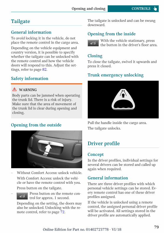
Tailgate
General informationTo avoid locking it in the vehicle, do notplace the remote control in the cargo area.
Depending on the vehicle equipment andcountry version, it is possible to specifywhether the tailgate can be unlocked withthe remote control and how the vehicledoors will respond to this. Adjust the set-tings, refer to page 82.
Safety information
WARNING
Body parts can be jammed when operatingthe trunk lid. There is a risk of injury.Make sure that the area of movement ofthe trunk lid is clear during opening andclosing.
Opening from the outside
– Without Comfort Access: unlock vehicle.
With Comfort Access: unlock the vehi-cle or have the remote control with you.
Press button on the tailgate.
– Press button on the remote con-trol for approx. 1 second.
Depending on the setting, the doors mayalso be unlocked. Unlocking with the re-mote control, refer to page 72.
The tailgate is unlocked and can be swungdownward.
Opening from the insideWith the vehicle stationary, pressthe button in the driver's floor area.
ClosingTo close the tailgate, swivel it upwards andpress it closed.
Trunk emergency unlocking
Pull the handle inside the cargo area.
The tailgate unlocks.
Driver profile
ConceptIn the driver profiles, individual settings forseveral drivers can be stored and called upagain when required.
General informationThere are three driver profiles with whichpersonal vehicle settings can be stored. Ev-ery remote control has one of these driverprofiles assigned.
If the vehicle is unlocked using a remotecontrol, the assigned personal driver profilewill be activated. All settings stored in thedriver profile are automatically applied.
Seite 79
Opening and closing CONTROLS
79Online Edition for Part no. 01402723778 - VI/18
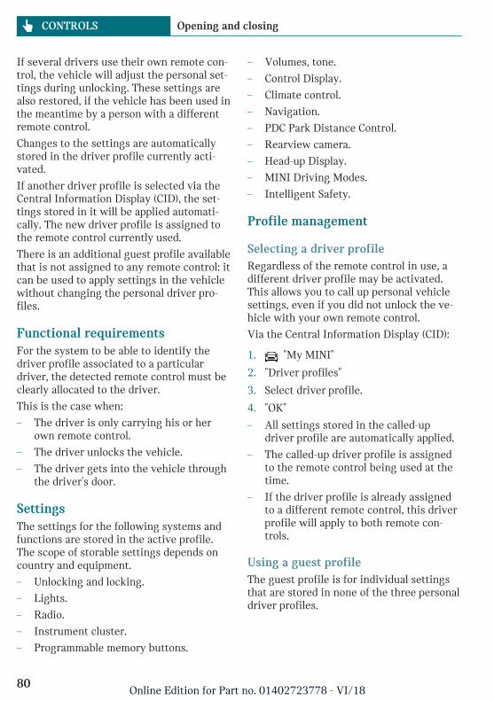
If several drivers use their own remote con-trol, the vehicle will adjust the personal set-tings during unlocking. These settings arealso restored, if the vehicle has been used inthe meantime by a person with a differentremote control.
Changes to the settings are automaticallystored in the driver profile currently acti-vated.
If another driver profile is selected via theCentral Information Display (CID), the set-tings stored in it will be applied automati-cally. The new driver profile is assigned tothe remote control currently used.
There is an additional guest profile availablethat is not assigned to any remote control: itcan be used to apply settings in the vehiclewithout changing the personal driver pro-files.
Functional requirementsFor the system to be able to identify thedriver profile associated to a particulardriver, the detected remote control must beclearly allocated to the driver.
This is the case when:
– The driver is only carrying his or herown remote control.
– The driver unlocks the vehicle.
– The driver gets into the vehicle throughthe driver's door.
SettingsThe settings for the following systems andfunctions are stored in the active profile.The scope of storable settings depends oncountry and equipment.
– Unlocking and locking.
– Lights.
– Radio.
– Instrument cluster.
– Programmable memory buttons.
– Volumes, tone.
– Control Display.
– Climate control.
– Navigation.
– PDC Park Distance Control.
– Rearview camera.
– Head-up Display.
– MINI Driving Modes.
– Intelligent Safety.
Profile management
Selecting a driver profileRegardless of the remote control in use, adifferent driver profile may be activated.This allows you to call up personal vehiclesettings, even if you did not unlock the ve-hicle with your own remote control.
Via the Central Information Display (CID):
1. "My MINI"
2. "Driver profiles"
3. Select driver profile.
4. "OK"
– All settings stored in the called-updriver profile are automatically applied.
– The called-up driver profile is assignedto the remote control being used at thetime.
– If the driver profile is already assignedto a different remote control, this driverprofile will apply to both remote con-trols.
Using a guest profileThe guest profile is for individual settingsthat are stored in none of the three personaldriver profiles.
Seite 80
CONTROLS Opening and closing
80Online Edition for Part no. 01402723778 - VI/18
Via the Central Information Display (CID):
1. "My MINI"
2. "Driver profiles"
3. "Drive off (guest)"
4. "OK"
The guest profile cannot be renamed. It isnot assigned to the current remote control.
Renaming a driver profileA personal name can be assigned to the ac-tive driver profile to avoid confusion be-tween the driver profiles.
Via the Central Information Display (CID):
1. "My MINI"
2. "Driver profiles"
3. Select driver profile.
The driver profile marked with thissymbol can be renamed.
4. "Change driver profile name"
5. Enter profile name.
6. Select the symbol.
Resetting a driver profileThe settings of the driver profile currentlyin use are reset to their factory settings.
Via the Central Information Display (CID):
1. "My MINI"
2. "Driver profiles"
3. Select driver profile.
The driver profile marked with thissymbol can be reset.
4. "Reset driver profile"
5. "OK"
Exporting driver profilesMost settings of the active driver profilecan be exported.
Exporting is helpful when storing and re-trieving personal settings, for instance be-fore delivering the vehicle to a workshop.The stored driver profiles can be taken intoanother vehicle.
Via the Central Information Display (CID):
1. "My MINI"
2. "Driver profiles"
3. Select driver profile.
The driver profile marked with thissymbol can be exported.
4. "Export driver profile (USB)"
Select USB storage device as needed.
Importing driver profilesProfiles stored on a USB storage device canbe imported via the USB interface.
The existing settings of the active driverprofile are overwritten with the settings ofthe imported driver profile.
Via the Central Information Display (CID):
1. "My MINI"
2. "Driver profiles"
3. Select the driver profile to overwrite.
The driver profile marked with thissymbol can be overwritten.
4. "Import driver profile (USB)"
Select USB storage device as needed.
5. Select the driver profile to be imported.
Displaying driver profiles during startThe driver profiles can be displayed duringeach start to select the desired profile.
Via the Central Information Display (CID):
1. "My MINI"
2. "Driver profiles"
3. "Show driver profiles at startup"
Seite 81
Opening and closing CONTROLS
81Online Edition for Part no. 01402723778 - VI/18
System limitsA clear assignment between the remotecontrol and driver may not be possible inthe following cases, for example.
– The passenger unlocks the vehicle withhis or her own remote control, but an-other person is driving.
– The driver unlocks the vehicle via Com-fort Access and has multiple remotecontrols with him or her.
– The driver changes, but the vehicle isnot locked and unlocked.
– Multiple remote controls are locatedoutside of the vehicle.
Settings
General informationDepending on the package and country ver-sion, various settings are available for theremote control functions.
These settings are stored for the driver pro-file, refer to page 79, currently used.
Unlocking
DoorsVia the Central Information Display (CID):
1. "My MINI"
2. "Vehicle settings"
3. "Doors/Key"
4. "Driver's door" or "All doors"
5. Select desired setting:
– "Driver's door only"
Only the driver's door and the fuelfiller flap are unlocked. Pressingagain unlocks the entire vehicle.
– "All doors"
The entire vehicle is unlocked.
TailgateVia the Central Information Display (CID):
1. "My MINI"
2. "Vehicle settings"
3. "Doors/Key"
4.
The text next to the symbol indicatesthe current setting.
5. Select desired setting:
– "Tailgate"
Only the tailgate is unlocked.
– "Tailgate and door(s)"
The tailgate and the doors are un-locked.
– "Tailgate opens after unlocking"
The vehicle must be unlocked beforethe tailgate can be used with the re-mote control.
– "Button lock"
It is not possible to use the tailgatevia the remote control.
Depending on the vehicle equipment andcountry version, this setting may not be of-fered.
Automatic lockingVia the Central Information Display (CID):
1. "My MINI"
2. "Vehicle settings"
3. "Doors/Key"
4. Select desired setting:
– "Lock automatically"
The vehicle locks automatically aftera short period of time if no door isopened after unlocking.
– "Lock after starting to drive"
The vehicle locks automatically afteryou drive off.
Seite 82
CONTROLS Opening and closing
82Online Edition for Part no. 01402723778 - VI/18
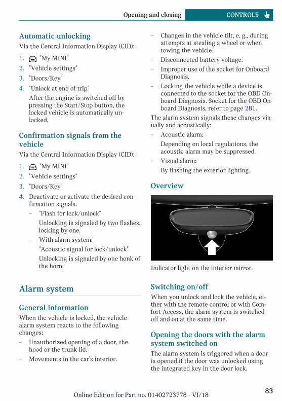
Automatic unlockingVia the Central Information Display (CID):
1. "My MINI"
2. "Vehicle settings"
3. "Doors/Key"
4. "Unlock at end of trip"
After the engine is switched off bypressing the Start/Stop button, thelocked vehicle is automatically un-locked.
Confirmation signals from thevehicleVia the Central Information Display (CID):
1. "My MINI"
2. "Vehicle settings"
3. "Doors/Key"
4. Deactivate or activate the desired con-firmation signals.
– "Flash for lock/unlock"
Unlocking is signaled by two flashes,locking by one.
– With alarm system:
"Acoustic signal for lock/unlock"
Unlocking is signaled by one honk ofthe horn.
Alarm system
General informationWhen the vehicle is locked, the vehiclealarm system reacts to the followingchanges:
– Unauthorized opening of a door, thehood or the trunk lid.
– Movements in the car's interior.
– Changes in the vehicle tilt, e. g., duringattempts at stealing a wheel or whentowing the vehicle.
– Disconnected battery voltage.
– Improper use of the socket for OnboardDiagnosis.
– Locking the vehicle while a device isconnected to the socket for the OBD On-board-Diagnosis. Socket for the OBD On-board Diagnosis, refer to page 281.
The alarm system signals these changes vis-ually and acoustically:
– Acoustic alarm:
Depending on local regulations, theacoustic alarm may be suppressed.
– Visual alarm:
By flashing the exterior lighting.
Overview
Indicator light on the interior mirror.
Switching on/offWhen you unlock and lock the vehicle, ei-ther with the remote control or with Com-fort Access, the alarm system is switchedoff and on at the same time.
Opening the doors with the alarmsystem switched onThe alarm system is triggered when a dooris opened if the door was unlocked usingthe integrated key in the door lock.
Seite 83
Opening and closing CONTROLS
83Online Edition for Part no. 01402723778 - VI/18
Switching off the alarm, refer to page 85.
Opening the tailgate with the alarmsystem switched onThe tailgate can be opened even when thealarm system is switched on.
After the tailgate is closed, it is locked andmonitored again provided the doors arelocked. The hazard warning system flashesonce.
Panic modeYou can trigger the alarm system if you findyourself in a dangerous situation.
– Press button on the remote con-trol and hold for at least 3 sec-onds.
– Briefly press the button on the remotecontrol three times in succession.
To switch off the alarm: press any button.
Signals of the indicator light– The indicator light flashes briefly every
2 seconds:
The alarm system is switched on.
– Indicator light flashes for approx.10 seconds, then it flashes briefly every2 seconds:
Interior motion sensor and tilt alarmsensor are not active, as doors, hood, ortailgate are not correctly closed. Cor-rectly closed access points are secured.
When the still open access points areclosed, interior motion sensor and tiltalarm sensor will be switched on.
– The indicator light goes out after un-locking:
The vehicle has not been tampered with.
– The indicator light flashes after unlock-ing until the engine ignition is switched
on, but no longer than approx. 5 mi-nutes:
An alarm has been triggered.
Tilt alarm sensorThe tilt of the vehicle is monitored.
The alarm system responds in situationssuch as attempts to steal a wheel or whenthe vehicle is towed.
Interior motion sensorThe car's interior is monitored to the heightof the seats. The alarm system is switchedon together with the interior motion sensoreven when the convertible top is open. Fall-ing objects such as leaves can trigger thealarm unintentionally.
Avoiding unintentional alarms
General informationThe tilt alarm sensor and interior motionsensor can trigger an alarm, although no un-authorized action occurred.
Possible situations for an unwanted alarm:
– In automatic vehicle washes.
– In duplex garages.
– During transport on trains carrying ve-hicles, at sea or on a trailer.
– With animals in the vehicle.
– When the vehicle is locked after start offueling.
The tilt alarm sensor and the interior mo-tion sensor can be switched off in such sit-uations.
Switching off the tilt alarm sensor andinterior motion sensor
Press the remote control buttonagain within 10 seconds as soon asthe vehicle is locked.
Seite 84
CONTROLS Opening and closing
84Online Edition for Part no. 01402723778 - VI/18
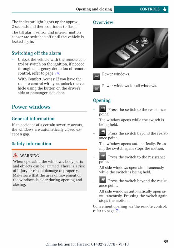
The indicator light lights up for approx.2 seconds and then continues to flash.
The tilt alarm sensor and interior motionsensor are switched off until the vehicle islocked again.
Switching off the alarm– Unlock the vehicle with the remote con-
trol or switch on the ignition, if neededthrough emergency detection of remotecontrol, refer to page 74.
– With Comfort Access: If you have theremote control with you, unlock the ve-hicle using the button on the driver'sside or passenger side door.
Power windows
General informationIf an accident of a certain severity occurs,the windows are automatically closed ex-cept a gap.
Safety information
WARNING
When operating the windows, body partsand objects can be jammed. There is a riskof injury or risk of damage to property.Make sure that the area of movement ofthe windows is clear during opening andclosing.
Overview
Power windows.
Power windows for all windows.
Opening
– Press the switch to the resistancepoint.
The window opens while the switch isbeing held.
– Press the switch beyond the resist-ance point.
The window opens automatically. Press-ing the switch again stops the motion.
– Press the switch to the resistancepoint.
All side windows open simultaneouslywhile the switch is being held.
– Press the switch beyond the resist-ance point.
All side windows automatically open si-multaneously. Pressing the switch againstops the motion.
Convenient opening via the remote control,refer to page 71.
Seite 85
Opening and closing CONTROLS
85Online Edition for Part no. 01402723778 - VI/18
Closing
– Pull the switch to the resistancepoint.
The window closes while the switch isbeing held.
– Pull the switch beyond the resist-ance point.
The window closes automatically if thedoor is closed. Pulling the switch againstops the motion.
– Pull the switch.
All side windows close simultaneouslywhile the switch is being held.
Convenient closing via the remote control,refer to page 72.
Closing via Comfort Access, refer topage 77.
Jam protection system
General informationIf closing force exceeds a specific thresholdas a window closes, closing is interrupted.
The window opens slightly.
Safety information
WARNING
Accessories on the windows such as an-tennas can impact jam protection. There isa risk of injury. Do not install accessoriesin the area of movement of the windows.
Closing without the jam protectionsystemIn case of danger from the outside or if icemight prevent normal closing, proceed asfollows:
1. Pull the switch past the resistancepoint and hold it there.
The window closes with limited jam pro-tection. If the closing force exceeds aspecific threshold, closing is inter-rupted.
2. Pull the switch past the resistancepoint again within approx. 4 secondsand hold it there.
The window closes without jam protec-tion.
Malfunction
General informationIn certain situations a window can only beoperated to a limited extent.
– After a power failure during the openingor closing process, the a window canonly be operated to a limited extent. Thesystem must be initialized in this case.
– The power window motors are equippedwith overheating protection. If a win-dow is opened and closed several timeswithin a short period of time, the over-heating protection switches the motoroff temporarily. Depending on the de-gree of overheating, it may only be pos-sible to close the window or it may notbe possible to operate it at all.
In this case: allow the power windowmotor to cool down.
Seite 86
CONTROLS Opening and closing
86Online Edition for Part no. 01402723778 - VI/18
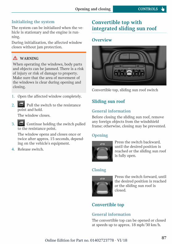
Initializing the systemThe system can be initialized when the ve-hicle is stationary and the engine is run-ning.
During initialization, the affected windowcloses without jam protection.
WARNING
When operating the windows, body partsand objects can be jammed. There is a riskof injury or risk of damage to property.Make sure that the area of movement ofthe windows is clear during opening andclosing.
1. Open the affected window completely.
2. Pull the switch to the resistancepoint and hold.
The window closes.
3. Continue holding the switch pulledto the resistance point.
The window opens and closes once ortwice after approx. 15 seconds, depend-ing on the vehicle's equipment.
4. Release switch.
Convertible top withintegrated sliding sun roof
Overview
Convertible top, sliding sun roof switch
Sliding sun roof
General informationBefore closing the sliding sun roof, removeany foreign objects from the windshieldframe; otherwise, closing may be prevented.
Opening
Press the switch backward,until the desired position isreached or the sliding sun roofis fully open.
Closing
Press the switch forward, untilthe desired position is reachedor the sliding sun roof isclosed.
Convertible top
General informationThe convertible top can be opened or closedat speeds up to approx. 18 mph/30 km/h.
Seite 87
Opening and closing CONTROLS
87Online Edition for Part no. 01402723778 - VI/18
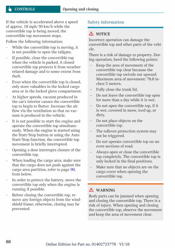
If the vehicle is accelerated above a speedof approx. 18 mph/30 km/h while theconvertible top is being moved, theconvertible top movement stops.
Follow the following information:
– While the convertible top is moving, itis not possible to open the tailgate.
– If possible, close the convertible topwhen the vehicle is parked. A closedconvertible top protects it from weather-related damage and to some extent fromtheft.
– Even when the convertible top is closed,only store valuables in the locked cargoarea or in the locked glove compartment.
– At higher speeds, vacuum produced inthe car's interior causes the convertibletop to begin to flutter. Increase the airflow via the ventilation so that no vac-uum is produced in the vehicle.
– It is not possible to start the engine andoperate the convertible top simultane-ously. When the engine is started usingthe Start/Stop button or using the AutoStart/Stop function, the convertible topmovement is briefly interrupted.
– Opening a door interrupts closure of theconvertible top.
– When loading the cargo area, make surethat the cargo does not push against thecargo area partition, refer to page 90,from below.
– In order to protect the battery, move theconvertible top only when the engine isrunning if possible.
– Before closing the convertible top, re-move any foreign objects from the wind-shield frame; otherwise, closing may beprevented.
Safety information
NOTICE
Incorrect operation can damage theconvertible top and other parts of the vehi-cle.
There is a risk of damage to property. Dur-ing operation, heed the following points:
– Keep the area of movement of theconvertible top clear because theconvertible top swivels out upward.Maximum area of movement: 78.8 in-ches/2 meters.
– Fully close the trunk lid.
– Do not leave the convertible top openfor more than a day while it is wet.
– Do not open the convertible top, if itis wet, covered in snow, iced up, ordirty.
– Do not place objects on theconvertible top.
– The rollover protection system maynot be triggered.
– Do not operate convertible top on un-even sections of road.
– Always open or close the convertibletop completely. The convertible top isonly locked in the final positions.
– Make sure that no objects are on thecargo cover when opening theconvertible top.
WARNING
Body parts can be jammed when openingand closing the convertible top. There is arisk of injury. When opening and closingthe convertible top, observe the movementand keep the area of movement clear.
Seite 88
CONTROLS Opening and closing
88Online Edition for Part no. 01402723778 - VI/18
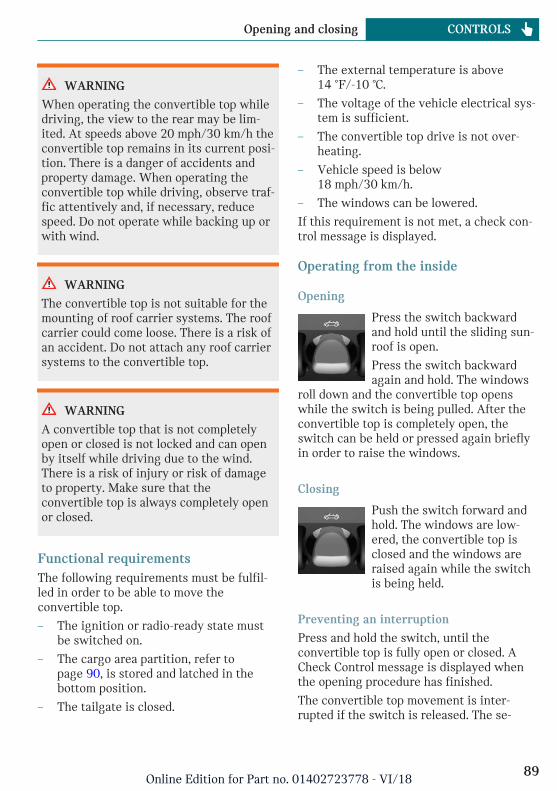
WARNING
When operating the convertible top whiledriving, the view to the rear may be lim-ited. At speeds above 20 mph/30 km/h theconvertible top remains in its current posi-tion. There is a danger of accidents andproperty damage. When operating theconvertible top while driving, observe traf-fic attentively and, if necessary, reducespeed. Do not operate while backing up orwith wind.
WARNING
The convertible top is not suitable for themounting of roof carrier systems. The roofcarrier could come loose. There is a risk ofan accident. Do not attach any roof carriersystems to the convertible top.
WARNING
A convertible top that is not completelyopen or closed is not locked and can openby itself while driving due to the wind.There is a risk of injury or risk of damageto property. Make sure that theconvertible top is always completely openor closed.
Functional requirementsThe following requirements must be fulfil-led in order to be able to move theconvertible top.
– The ignition or radio-ready state mustbe switched on.
– The cargo area partition, refer topage 90, is stored and latched in thebottom position.
– The tailgate is closed.
– The external temperature is above14 ℉/-10 ℃.
– The voltage of the vehicle electrical sys-tem is sufficient.
– The convertible top drive is not over-heating.
– Vehicle speed is below18 mph/30 km/h.
– The windows can be lowered.
If this requirement is not met, a check con-trol message is displayed.
Operating from the inside
Opening
Press the switch backwardand hold until the sliding sun-roof is open.
Press the switch backwardagain and hold. The windows
roll down and the convertible top openswhile the switch is being pulled. After theconvertible top is completely open, theswitch can be held or pressed again brieflyin order to raise the windows.
Closing
Push the switch forward andhold. The windows are low-ered, the convertible top isclosed and the windows areraised again while the switchis being held.
Preventing an interruption
Press and hold the switch, until theconvertible top is fully open or closed. ACheck Control message is displayed whenthe opening procedure has finished.
The convertible top movement is inter-rupted if the switch is released. The se-
Seite 89
Opening and closing CONTROLS
89Online Edition for Part no. 01402723778 - VI/18
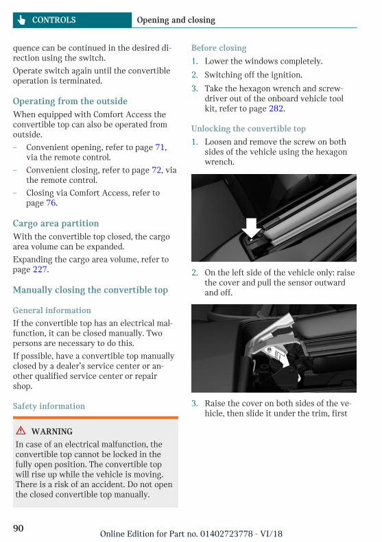
quence can be continued in the desired di-rection using the switch.
Operate switch again until the convertibleoperation is terminated.
Operating from the outsideWhen equipped with Comfort Access theconvertible top can also be operated fromoutside.
– Convenient opening, refer to page 71,via the remote control.
– Convenient closing, refer to page 72, viathe remote control.
– Closing via Comfort Access, refer topage 76.
Cargo area partitionWith the convertible top closed, the cargoarea volume can be expanded.
Expanding the cargo area volume, refer topage 227.
Manually closing the convertible top
General information
If the convertible top has an electrical mal-function, it can be closed manually. Twopersons are necessary to do this.
If possible, have a convertible top manuallyclosed by a dealer’s service center or an-other qualified service center or repairshop.
Safety information
WARNING
In case of an electrical malfunction, theconvertible top cannot be locked in thefully open position. The convertible topwill rise up while the vehicle is moving.There is a risk of an accident. Do not openthe closed convertible top manually.
Before closing
1. Lower the windows completely.
2. Switching off the ignition.
3. Take the hexagon wrench and screw-driver out of the onboard vehicle toolkit, refer to page 282.
Unlocking the convertible top
1. Loosen and remove the screw on bothsides of the vehicle using the hexagonwrench.
2. On the left side of the vehicle only: raisethe cover and pull the sensor outwardand off.
3. Raise the cover on both sides of the ve-hicle, then slide it under the trim, first
Seite 90
CONTROLS Opening and closing
90Online Edition for Part no. 01402723778 - VI/18
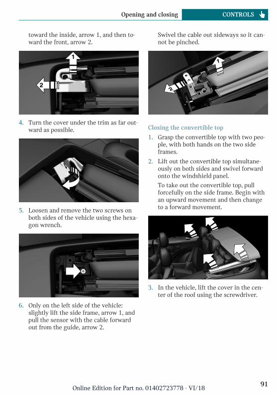
toward the inside, arrow 1, and then to-ward the front, arrow 2.
4. Turn the cover under the trim as far out-ward as possible.
5. Loosen and remove the two screws onboth sides of the vehicle using the hexa-gon wrench.
6. Only on the left side of the vehicle:slightly lift the side frame, arrow 1, andpull the sensor with the cable forwardout from the guide, arrow 2.
Swivel the cable out sideways so it can-not be pinched.
Closing the convertible top
1. Grasp the convertible top with two peo-ple, with both hands on the two sideframes.
2. Lift out the convertible top simultane-ously on both sides and swivel forwardonto the windshield panel.
To take out the convertible top, pullforcefully on the side frame. Begin withan upward movement and then changeto a forward movement.
3. In the vehicle, lift the cover in the cen-ter of the roof using the screwdriver.
Seite 91
Opening and closing CONTROLS
91Online Edition for Part no. 01402723778 - VI/18
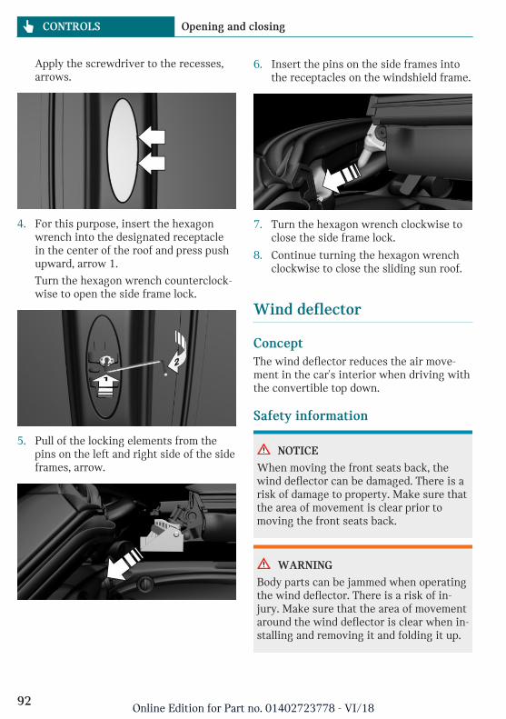
Apply the screwdriver to the recesses,arrows.
4. For this purpose, insert the hexagonwrench into the designated receptaclein the center of the roof and press pushupward, arrow 1.
Turn the hexagon wrench counterclock-wise to open the side frame lock.
5. Pull of the locking elements from thepins on the left and right side of the sideframes, arrow.
6. Insert the pins on the side frames intothe receptacles on the windshield frame.
7. Turn the hexagon wrench clockwise toclose the side frame lock.
8. Continue turning the hexagon wrenchclockwise to close the sliding sun roof.
Wind deflector
ConceptThe wind deflector reduces the air move-ment in the car's interior when driving withthe convertible top down.
Safety information
NOTICE
When moving the front seats back, thewind deflector can be damaged. There is arisk of damage to property. Make sure thatthe area of movement is clear prior tomoving the front seats back.
WARNING
Body parts can be jammed when operatingthe wind deflector. There is a risk of in-jury. Make sure that the area of movementaround the wind deflector is clear when in-stalling and removing it and folding it up.
Seite 92
CONTROLS Opening and closing
92Online Edition for Part no. 01402723778 - VI/18
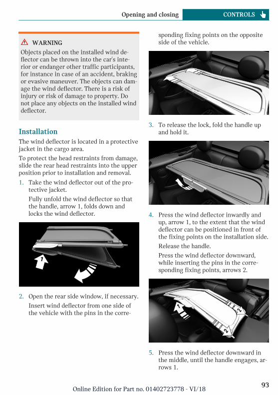
WARNING
Objects placed on the installed wind de-flector can be thrown into the car's inte-rior or endanger other traffic participants,for instance in case of an accident, brakingor evasive maneuver. The objects can dam-age the wind deflector. There is a risk ofinjury or risk of damage to property. Donot place any objects on the installed winddeflector.
InstallationThe wind deflector is located in a protectivejacket in the cargo area.
To protect the head restraints from damage,slide the rear head restraints into the upperposition prior to installation and removal.
1. Take the wind deflector out of the pro-tective jacket.
Fully unfold the wind deflector so thatthe handle, arrow 1, folds down andlocks the wind deflector.
2. Open the rear side window, if necessary.
Insert wind deflector from one side ofthe vehicle with the pins in the corre-
sponding fixing points on the oppositeside of the vehicle.
3. To release the lock, fold the handle upand hold it.
4. Press the wind deflector inwardly andup, arrow 1, to the extent that the winddeflector can be positioned in front ofthe fixing points on the installation side.
Release the handle.
Press the wind deflector downward,while inserting the pins in the corre-sponding fixing points, arrows 2.
5. Press the wind deflector downward inthe middle, until the handle engages, ar-rows 1.
Seite 93
Opening and closing CONTROLS
93Online Edition for Part no. 01402723778 - VI/18
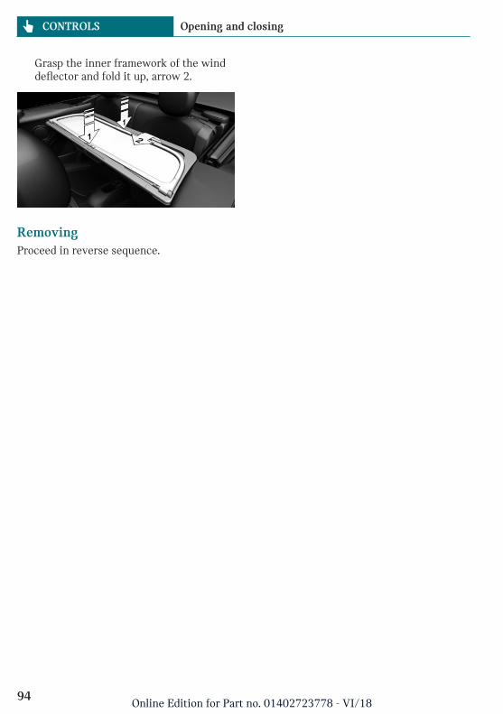
Grasp the inner framework of the winddeflector and fold it up, arrow 2.
RemovingProceed in reverse sequence.
Seite 94
CONTROLS Opening and closing
94Online Edition for Part no. 01402723778 - VI/18
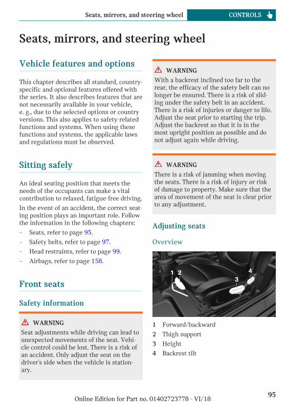
Seats, mirrors, and steering wheel
Vehicle features and options
This chapter describes all standard, country-specific and optional features offered withthe series. It also describes features that arenot necessarily available in your vehicle,e. g., due to the selected options or countryversions. This also applies to safety-relatedfunctions and systems. When using thesefunctions and systems, the applicable lawsand regulations must be observed.
Sitting safely
An ideal seating position that meets theneeds of the occupants can make a vitalcontribution to relaxed, fatigue-free driving.
In the event of an accident, the correct seat-ing position plays an important role. Followthe information in the following chapters:
– Seats, refer to page 95.
– Safety belts, refer to page 97.
– Head restraints, refer to page 99.
– Airbags, refer to page 158.
Front seats
Safety information
WARNING
Seat adjustments while driving can lead tounexpected movements of the seat. Vehi-cle control could be lost. There is a risk ofan accident. Only adjust the seat on thedriver's side when the vehicle is station-ary.
WARNING
With a backrest inclined too far to therear, the efficacy of the safety belt can nolonger be ensured. There is a risk of slid-ing under the safety belt in an accident.There is a risk of injuries or danger to life.Adjust the seat prior to starting the trip.Adjust the backrest so that it is in themost upright position as possible and donot adjust again while driving.
WARNING
There is a risk of jamming when movingthe seats. There is a risk of injury or riskof damage to property. Make sure that thearea of movement of the seat is clear priorto any adjustment.
Adjusting seats
Overview
1 Forward/backward
2 Thigh support
3 Height
4 Backrest tilt
Seite 95
Seats, mirrors, and steering wheel CONTROLS
95Online Edition for Part no. 01402723778 - VI/18
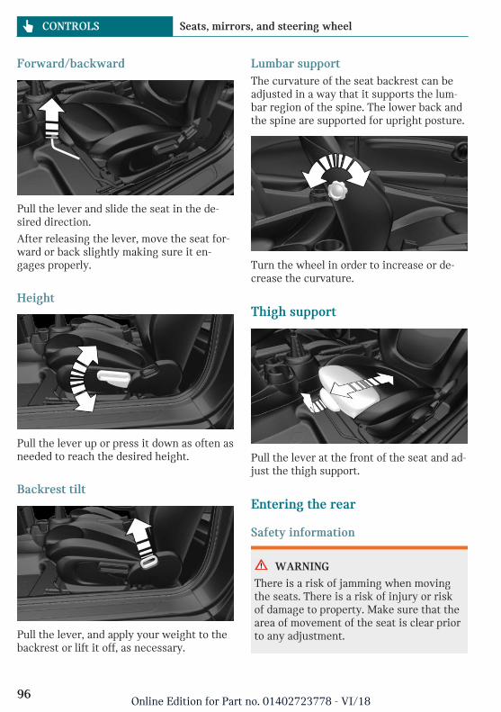
Forward/backward
Pull the lever and slide the seat in the de-sired direction.
After releasing the lever, move the seat for-ward or back slightly making sure it en-gages properly.
Height
Pull the lever up or press it down as often asneeded to reach the desired height.
Backrest tilt
Pull the lever, and apply your weight to thebackrest or lift it off, as necessary.
Lumbar supportThe curvature of the seat backrest can beadjusted in a way that it supports the lum-bar region of the spine. The lower back andthe spine are supported for upright posture.
Turn the wheel in order to increase or de-crease the curvature.
Thigh support
Pull the lever at the front of the seat and ad-just the thigh support.
Entering the rear
Safety information
WARNING
There is a risk of jamming when movingthe seats. There is a risk of injury or riskof damage to property. Make sure that thearea of movement of the seat is clear priorto any adjustment.
Seite 96
CONTROLS Seats, mirrors, and steering wheel
96Online Edition for Part no. 01402723778 - VI/18
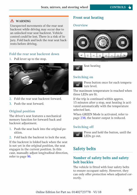
WARNING
Unexpected movements of the rear seatbackrest while driving may occur due toan unlocked rear seat backrest. Vehiclecontrol could be lost. There is a risk of in-jury. Fold back and lock the rear seat back-rests before driving.
Fold the rear seat backrest down1. Pull lever up to the stop.
2. Fold the rear seat backrest forward.
3. Push the seat forward.
Original positionThe driver's seat features a mechanicalmemory function for forward/back andbackrest adjustment.
1. Push the seat back into the original po-sition.
2. Fold back the backrest to lock the seat.
If the backrest is folded back when the seatis not yet in the original position, the seatengages in the current position. In thiscase, manually adjust longitudinal direction,refer to page 96.
Front seat heating
Overview
Seat heating
Switching on
Press button once for each tempera-ture level.
The maximum temperature is reached whenthree LEDs are lit.
If the trip is continued within approx.15 minutes after a stop, seat heating is acti-vated automatically with the temperatureselected last.
When GREEN Mode is activated, refer topage 238, the heater output is reduced.
Switching off
Press and hold the button, until theLEDs go out.
Safety belts
Number of safety belts and safetybelt bucklesThe vehicle is fitted with four safety beltsto ensure occupant safety. However, theycan only offer protection when adjusted cor-rectly.
Seite 97
Seats, mirrors, and steering wheel CONTROLS
97Online Edition for Part no. 01402723778 - VI/18
General informationAlways make sure that safety belts are be-ing worn by all occupants before driving off.Although airbags enhance safety by provid-ing added protection, they are not a substi-tute for safety belts.
The upper shoulder strap's anchorage pointwill be correct for adult seat occupants ofevery build if the seat is correctly adjusted.
Safety information
WARNING
Use of a safety belt to buckle more thanone person will potentially defeat the abil-ity of the safety belt to serve its protectivefunction. There is a risk of injuries or dan-ger to life. Do not allow more than one per-son to wear a single safety belt. Infantsand children are not allowed on an occu-pant's lap, but must be transported and se-cured in designated child restraint sys-tems.
WARNING
The efficacy of safety gear, includingsafety belts, can be limited or lost whensafety belts are fastened incorrectly. Anincorrectly fastened safety belt can causeadditional injuries, for instance in theevent of an accident or during braking andevasive maneuvers. There is a risk of inju-ries or danger to life. Make sure that alloccupants are wearing safety belts cor-rectly.
WARNING
The efficacy of safety gear, includingsafety belts, may not be fully functional orfail in the following situations:
– The safety belts or safety belt bucklesare damaged, soiled, or changed inany other way.
– Belt tensioners or belt retractorswere modified.
Safety belts can be imperceptibly damagedin the event of an accident. There is a riskof injuries or danger to life. Do not modifysafety belts, safety belt buckles, belt ten-sioners, belt retractors or belt anchors andkeep them clean. Have the safety beltschecked after an accident at the dealer’sservice center or another qualified servicecenter or repair shop.
Correct use of safety belts– Wear the safety belt twist-free and tight
to your body over your lap and should-ers.
– Wear the safety belt deep on your hipsover your lap. The safety belt may notpress on your stomach.
– Do not rub the safety belt against sharpedges, or guide it or jam it in acrosshard or fragile objects.
– Avoid thick clothing.
– Re-tighten the safety belt frequently up-ward around your upper body.
Buckling the safety belt1. Slowly guide the safety belt out of the
holder when fastening it.
Seite 98
CONTROLS Seats, mirrors, and steering wheel
98Online Edition for Part no. 01402723778 - VI/18
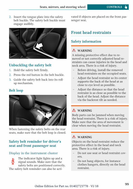
2. Insert the tongue plate into the safetybelt buckle. The safety belt buckle mustengage audibly.
Unbuckling the safety belt1. Hold the safety belt firmly.
2. Press the red button in the belt buckle.
3. Guide the safety belt back into its roll-up mechanism.
Belt loop
When fastening the safety belts on the rearseats, make sure that the belt loop is closed.
Safety belt reminder for driver'sseat and front passenger seat
Display in the instrument cluster
The indicator light lights up and asignal sounds. Make sure that thesafety belts are positioned correctly.
The safety belt reminder can also be acti-
vated if objects are placed on the front pas-senger seat.
Front head restraints
Safety information
WARNING
A missing protective effect due to re-moved or not correctly adjusted head re-straints can cause injuries in the head andneck area. There is a risk of injury.
– Before driving, install the removedhead restraints on the occupied seats.
– Adjust the head restraint so its centersupports the back of the head at asclose to eye level as possible.
– Adjust the distance so that the headrestraint is as close as possible to theback of the head. Adjust the distancevia the backrest tilt as needed.
WARNING
Body parts can be jammed when movingthe head restraint. There is a risk of injury.Make sure that the area of movement isclear when moving the head restraint.
WARNING
Objects on the head restraint reduce theprotective effect in the head and neckarea. There is a risk of injury.
– Do not use seat or head restraint cov-ers.
– Do not hang objects, for instanceclothes hangers, directly on the headrestraint.
Seite 99
Seats, mirrors, and steering wheel CONTROLS
99Online Edition for Part no. 01402723778 - VI/18
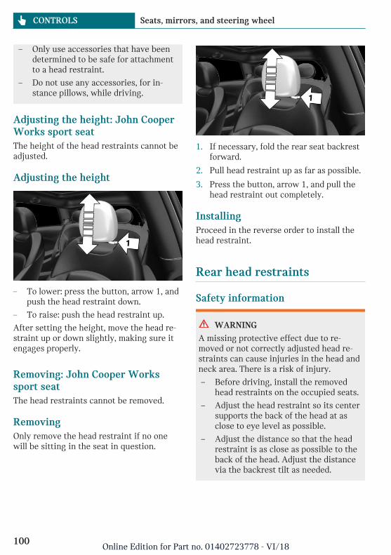
– Only use accessories that have beendetermined to be safe for attachmentto a head restraint.
– Do not use any accessories, for in-stance pillows, while driving.
Adjusting the height: John CooperWorks sport seatThe height of the head restraints cannot beadjusted.
Adjusting the height
– To lower: press the button, arrow 1, andpush the head restraint down.
– To raise: push the head restraint up.
After setting the height, move the head re-straint up or down slightly, making sure itengages properly.
Removing: John Cooper Workssport seatThe head restraints cannot be removed.
RemovingOnly remove the head restraint if no onewill be sitting in the seat in question.
1. If necessary, fold the rear seat backrestforward.
2. Pull head restraint up as far as possible.
3. Press the button, arrow 1, and pull thehead restraint out completely.
InstallingProceed in the reverse order to install thehead restraint.
Rear head restraints
Safety information
WARNING
A missing protective effect due to re-moved or not correctly adjusted head re-straints can cause injuries in the head andneck area. There is a risk of injury.
– Before driving, install the removedhead restraints on the occupied seats.
– Adjust the head restraint so its centersupports the back of the head at asclose to eye level as possible.
– Adjust the distance so that the headrestraint is as close as possible to theback of the head. Adjust the distancevia the backrest tilt as needed.
Seite 100
CONTROLS Seats, mirrors, and steering wheel
100Online Edition for Part no. 01402723778 - VI/18
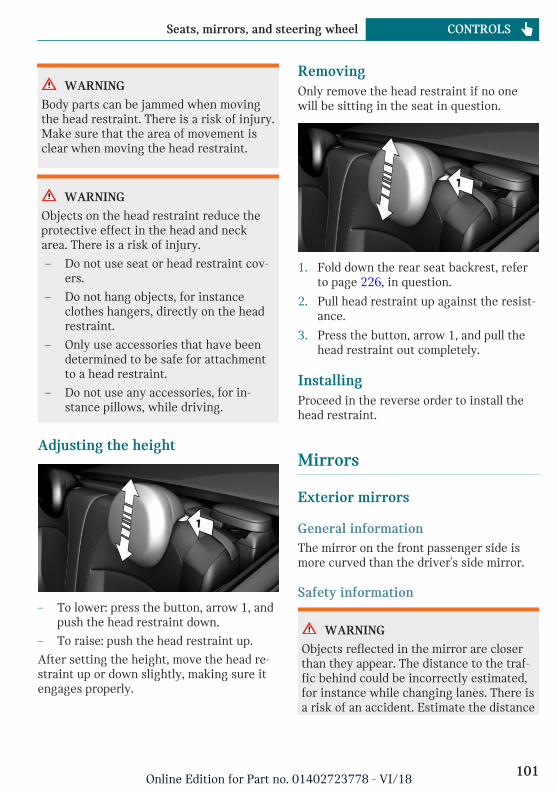
WARNING
Body parts can be jammed when movingthe head restraint. There is a risk of injury.Make sure that the area of movement isclear when moving the head restraint.
WARNING
Objects on the head restraint reduce theprotective effect in the head and neckarea. There is a risk of injury.
– Do not use seat or head restraint cov-ers.
– Do not hang objects, for instanceclothes hangers, directly on the headrestraint.
– Only use accessories that have beendetermined to be safe for attachmentto a head restraint.
– Do not use any accessories, for in-stance pillows, while driving.
Adjusting the height
– To lower: press the button, arrow 1, andpush the head restraint down.
– To raise: push the head restraint up.
After setting the height, move the head re-straint up or down slightly, making sure itengages properly.
RemovingOnly remove the head restraint if no onewill be sitting in the seat in question.
1. Fold down the rear seat backrest, referto page 226, in question.
2. Pull head restraint up against the resist-ance.
3. Press the button, arrow 1, and pull thehead restraint out completely.
InstallingProceed in the reverse order to install thehead restraint.
Mirrors
Exterior mirrors
General informationThe mirror on the front passenger side ismore curved than the driver's side mirror.
Safety information
WARNING
Objects reflected in the mirror are closerthan they appear. The distance to the traf-fic behind could be incorrectly estimated,for instance while changing lanes. There isa risk of an accident. Estimate the distance
Seite 101
Seats, mirrors, and steering wheel CONTROLS
101Online Edition for Part no. 01402723778 - VI/18
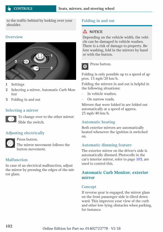
to the traffic behind by looking over yourshoulder.
Overview
1 Settings
2 Selecting a mirror, Automatic Curb Mon-itor
3 Folding in and out
Selecting a mirror
To change over to the other mirror:
Slide the switch.
Adjusting electrically
Press button.
The mirror movement follows thebutton movement.
MalfunctionIn case of an electrical malfunction, adjustthe mirror by pressing the edges of the mir-ror glass.
Folding in and out
NOTICE
Depending on the vehicle width, the vehi-cle can be damaged in vehicle washes.There is a risk of damage to property. Be-fore washing, fold in the mirrors by handor with the button.
Press button.
Folding is only possible up to a speed of ap-prox. 15 mph/20 km/h.
Folding the mirrors in and out is helpful inthe following situations:
– In vehicle washes.
– On narrow roads.
Mirrors that were folded in are folded outautomatically at a speed of approx.25 mph/40 km/h.
Automatic heatingBoth exterior mirrors are automaticallyheated whenever the ignition is switchedon.
Automatic dimming featureThe exterior mirror on the driver's side isautomatically dimmed. Photocells in thecar's interior mirror, refer to page 103, areused to control this.
Automatic Curb Monitor, exteriormirror
ConceptIf reverse gear is engaged, the mirror glasson the front passenger side is tilted down-ward. This improves your view of the curband other low-lying obstacles when parking,for instance.
Seite 102
CONTROLS Seats, mirrors, and steering wheel
102Online Edition for Part no. 01402723778 - VI/18
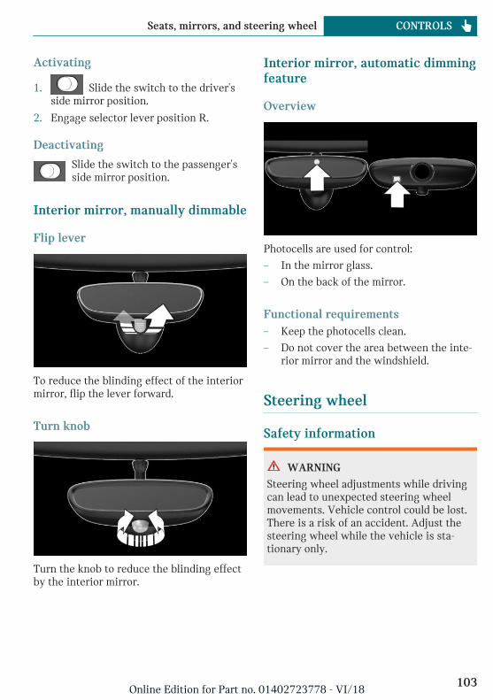
Activating
1. Slide the switch to the driver'sside mirror position.
2. Engage selector lever position R.
Deactivating
Slide the switch to the passenger'sside mirror position.
Interior mirror, manually dimmable
Flip lever
To reduce the blinding effect of the interiormirror, flip the lever forward.
Turn knob
Turn the knob to reduce the blinding effectby the interior mirror.
Interior mirror, automatic dimmingfeature
Overview
Photocells are used for control:
– In the mirror glass.
– On the back of the mirror.
Functional requirements– Keep the photocells clean.
– Do not cover the area between the inte-rior mirror and the windshield.
Steering wheel
Safety information
WARNING
Steering wheel adjustments while drivingcan lead to unexpected steering wheelmovements. Vehicle control could be lost.There is a risk of an accident. Adjust thesteering wheel while the vehicle is sta-tionary only.
Seite 103
Seats, mirrors, and steering wheel CONTROLS
103Online Edition for Part no. 01402723778 - VI/18
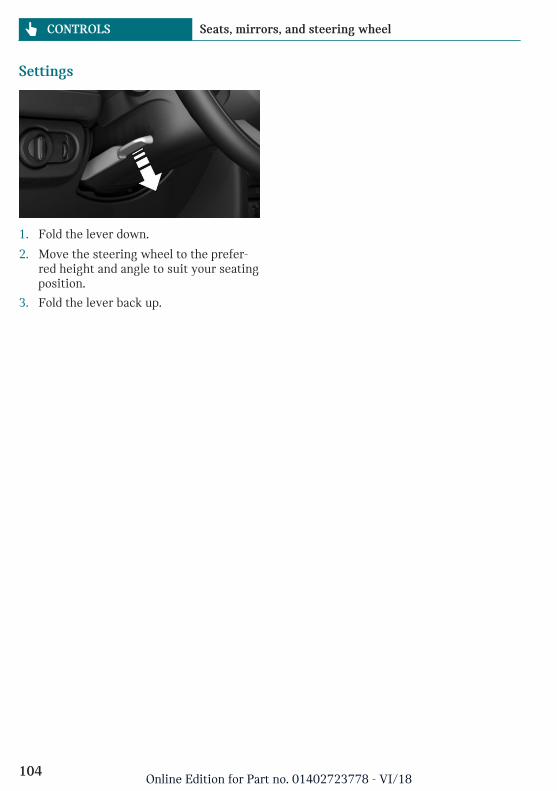
Settings
1. Fold the lever down.
2. Move the steering wheel to the prefer-red height and angle to suit your seatingposition.
3. Fold the lever back up.
Seite 104
CONTROLS Seats, mirrors, and steering wheel
104Online Edition for Part no. 01402723778 - VI/18
Transporting children safely
Vehicle features and options
This chapter describes all standard, country-specific and optional features offered withthe series. It also describes features that arenot necessarily available in your vehicle,
e. g., due to the selected options or countryversions. This also applies to safety-relatedfunctions and systems. When using thesefunctions and systems, the applicable lawsand regulations must be observed.
The right place for children
Safety information
WARNING
Unattended children or animals can causethe vehicle to move and endanger them-selves and traffic, for instance due to thefollowing actions:
– Pressing the Start/Stop button.
– Releasing the parking brake.
– Opening and closing the doors orwindows.
– Engaging selector lever position N.
– Using vehicle equipment.
There is a risk of accidents or injuries. Donot leave children or animals unattendedin the vehicle. Take the remote controlwith you when exiting and lock the vehi-cle.
Always transport children in therear seat
General informationAccident research shows that the safestplace for children is in the rear seat.
Transport children younger than 13 years ofage or shorter than 5 ft/150 cm only in therear seat in suitable child restraint systems
designed for the age, weight and size of thechild. Children 13 years of age or older mustwear a safety belt as soon as a suitable childrestraint system can no longer be used dueto their age, weight, and size.
Safety information
WARNING
The safety belt cannot be fastened cor-rectly on children shorter than 5 ft,150 cm without suitable additional childrestraint systems. The efficacy of safetygear, including safety belts, can be limitedor lost when safety belts are fastened in-correctly. An incorrectly fastened safetybelt can cause additional injuries, for in-stance in the event of an accident or dur-ing braking and evasive maneuvers. Thereis a risk of injuries or danger to life. Se-cure children shorter than 5 ft, 150 cm us-ing suitable child restraint systems.
Children on the front passengerseat
General informationBefore using a child restraint system on thefront passenger seat, ensure that the front,knee, and side airbags on the front passen-
Seite 105
Transporting children safely CONTROLS
105Online Edition for Part no. 01402723778 - VI/18
ger side are deactivated. Automatic deacti-vation of front-seat passenger airbags, referto page 160.
Safety information
WARNING
Active front-seat passenger airbags can in-jure a child in a child restraint systemwhen the airbags are activated. There is arisk of injury. Make sure that the front-seat passenger airbags are deactivated andthat the PASSENGER AIRBAG OFF indica-tor light lights up.
WARNING
The stability of the child restraint systemis limited or compromised with incorrectseat adjustment or improper installation ofthe child seat. There is a risk of injuries ordanger to life. Make sure that the child re-straint system fits securely against thebackrest. If possible, adjust the backresttilt for all affected backrests and correctlyadjust the seats. Make sure that seats andbackrests are securely engaged or locked.If possible, adjust the height of the headrestraints or remove them.
Installing child restraint sys-tems
General informationPay attention to the specifications of thechild restraint system manufacturer whenselecting, installing, and using child re-straint systems.
In order to faciliate the installation of aback-facing child restraint system in therear:
Move the front passenger seat as far up aspossible before folding down the backrest.
Safety information
WARNING
The protective effect of damaged child re-straint systems or of child restraint sys-tems exposed to an accident and their fas-tening systems can be limited or lost. Achild can e.g.,not sufficiently restrained,for instance in the event of an accident orbraking and evasive maneuvers. There is arisk of injuries or danger to life. Have dam-aged child restraint systems or of child re-straint systems exposed to an accident andtheir fastening systems checked and possi-bly replaced by the dealer’s service centeror another qualified service center or re-pair shop.
WARNING
The stability of the child restraint systemis limited or compromised with incorrectseat adjustment or improper installation ofthe child seat. There is a risk of injuries ordanger to life. Make sure that the child re-straint system fits securely against thebackrest. If possible, adjust the backresttilt for all affected backrests and correctlyadjust the seats. Make sure that seats andbackrests are securely engaged or locked.If possible, adjust the height of the headrestraints or remove them.
On the rear seatsIn order to facilitate the installation of aback-facing child restraint system:
Move the front passenger seat as far up aspossible before folding down the backrest.
Seite 106
CONTROLS Transporting children safely
106Online Edition for Part no. 01402723778 - VI/18
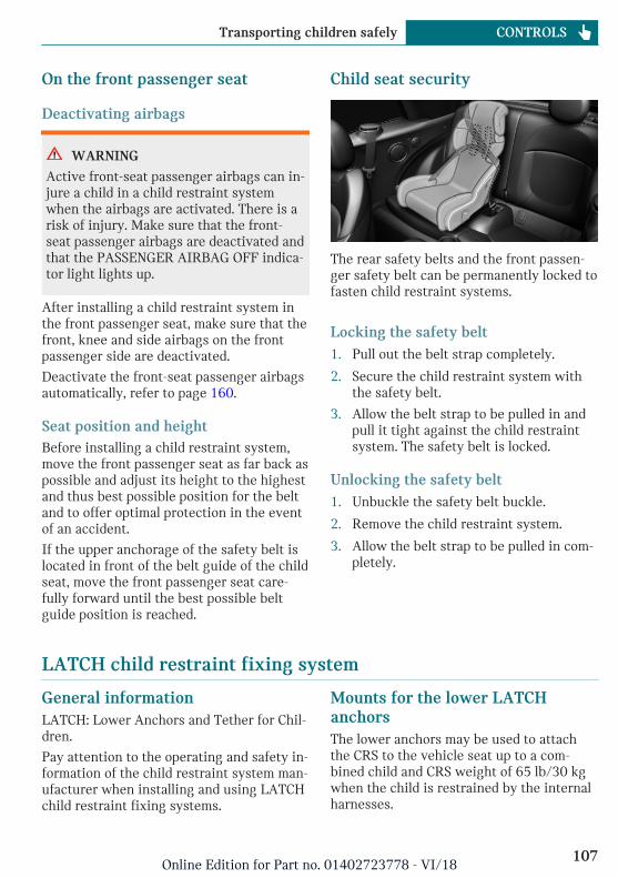
On the front passenger seat
Deactivating airbags
WARNING
Active front-seat passenger airbags can in-jure a child in a child restraint systemwhen the airbags are activated. There is arisk of injury. Make sure that the front-seat passenger airbags are deactivated andthat the PASSENGER AIRBAG OFF indica-tor light lights up.
After installing a child restraint system inthe front passenger seat, make sure that thefront, knee and side airbags on the frontpassenger side are deactivated.
Deactivate the front-seat passenger airbagsautomatically, refer to page 160.
Seat position and heightBefore installing a child restraint system,move the front passenger seat as far back aspossible and adjust its height to the highestand thus best possible position for the beltand to offer optimal protection in the eventof an accident.
If the upper anchorage of the safety belt islocated in front of the belt guide of the childseat, move the front passenger seat care-fully forward until the best possible beltguide position is reached.
Child seat security
The rear safety belts and the front passen-ger safety belt can be permanently locked tofasten child restraint systems.
Locking the safety belt1. Pull out the belt strap completely.
2. Secure the child restraint system withthe safety belt.
3. Allow the belt strap to be pulled in andpull it tight against the child restraintsystem. The safety belt is locked.
Unlocking the safety belt1. Unbuckle the safety belt buckle.
2. Remove the child restraint system.
3. Allow the belt strap to be pulled in com-pletely.
LATCH child restraint fixing system
General informationLATCH: Lower Anchors and Tether for Chil-dren.
Pay attention to the operating and safety in-formation of the child restraint system man-ufacturer when installing and using LATCHchild restraint fixing systems.
Mounts for the lower LATCHanchorsThe lower anchors may be used to attachthe CRS to the vehicle seat up to a com-bined child and CRS weight of 65 lb/30 kgwhen the child is restrained by the internalharnesses.
Seite 107
Transporting children safely CONTROLS
107Online Edition for Part no. 01402723778 - VI/18
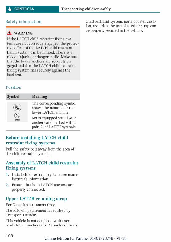
Safety information
WARNING
If the LATCH child restraint fixing sys-tems are not correctly engaged, the protec-tive effect of the LATCH child restraintfixing system can be limited. There is arisk of injuries or danger to life. Make surethat the lower anchors are securely en-gaged and that the LATCH child restraintfixing system fits securely against thebackrest.
Position
Symbol Meaning
The corresponding symbolshows the mounts for thelower LATCH anchors.
Seats equipped with loweranchors are marked with apair, 2, of LATCH symbols.
Before installing LATCH childrestraint fixing systemsPull the safety belt away from the area ofthe child restraint system.
Assembly of LATCH child restraintfixing systems1. Install child restraint system, see manu-
facturer's information.
2. Ensure that both LATCH anchors areproperly connected.
Upper LATCH retaining strapFor Canadian customers Only.
The following statement is required byTransport Canada:
This vehicle is not equipped with user-ready tether anchorages. As such neither a
child restraint system, nor a booster cush-ion, requiring the use of a tether strap canbe properly secured in the vehicle.
Seite 108
CONTROLS Transporting children safely
108Online Edition for Part no. 01402723778 - VI/18
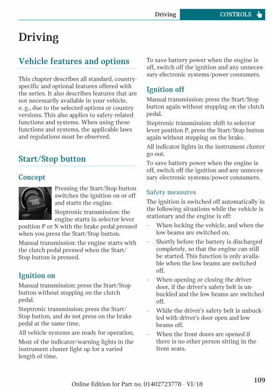
Driving
Vehicle features and options
This chapter describes all standard, country-specific and optional features offered withthe series. It also describes features that arenot necessarily available in your vehicle,e. g., due to the selected options or countryversions. This also applies to safety-relatedfunctions and systems. When using thesefunctions and systems, the applicable lawsand regulations must be observed.
Start/Stop button
ConceptPressing the Start/Stop buttonswitches the ignition on or offand starts the engine.
Steptronic transmission: theengine starts in selector lever
position P or N with the brake pedal pressedwhen you press the Start/Stop button.
Manual transmission: the engine starts withthe clutch pedal pressed when the Start/Stop button is pressed.
Ignition onManual transmission: press the Start/Stopbutton without stepping on the clutchpedal.
Steptronic transmission: press the Start/Stop button, and do not press on the brakepedal at the same time.
All vehicle systems are ready for operation.
Most of the indicator/warning lights in theinstrument cluster light up for a variedlength of time.
To save battery power when the engine isoff, switch off the ignition and any unneces-sary electronic systems/power consumers.
Ignition offManual transmission: press the Start/Stopbutton again without stepping on the clutchpedal.
Steptronic transmission: shift to selectorlever position P, press the Start/Stop buttonagain without stepping on the brake.
All indicator lights in the instrument clustergo out.
To save battery power when the engine isoff, switch off the ignition and any unneces-sary electronic systems/power consumers.
Safety measuresThe ignition is switched off automatically inthe following situations while the vehicle isstationary and the engine is off:
– When locking the vehicle, and when thelow beams are switched on.
– Shortly before the battery is dischargedcompletely, so that the engine can stillbe started. This function is only availa-ble when the low beams are switchedoff.
– When opening or closing the driverdoor, if the driver's safety belt is un-buckled and the low beams are switchedoff.
– While the driver's safety belt is unbuck-led with driver's door open and lowbeams off.
– When the front doors are opened ifthere is no other person sitting in thefront seats.
Seite 109
Driving CONTROLS
109Online Edition for Part no. 01402723778 - VI/18
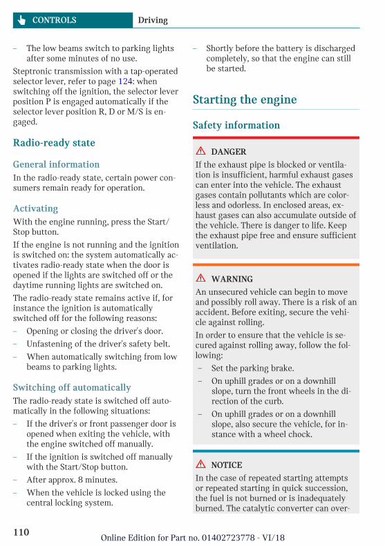
– The low beams switch to parking lightsafter some minutes of no use.
Steptronic transmission with a tap-operatedselector lever, refer to page 124: whenswitching off the ignition, the selector leverposition P is engaged automatically if theselector lever position R, D or M/S is en-gaged.
Radio-ready state
General informationIn the radio-ready state, certain power con-sumers remain ready for operation.
ActivatingWith the engine running, press the Start/Stop button.
If the engine is not running and the ignitionis switched on: the system automatically ac-tivates radio-ready state when the door isopened if the lights are switched off or thedaytime running lights are switched on.
The radio-ready state remains active if, forinstance the ignition is automaticallyswitched off for the following reasons:
– Opening or closing the driver's door.
– Unfastening of the driver's safety belt.
– When automatically switching from lowbeams to parking lights.
Switching off automaticallyThe radio-ready state is switched off auto-matically in the following situations:
– If the driver's or front passenger door isopened when exiting the vehicle, withthe engine switched off manually.
– If the ignition is switched off manuallywith the Start/Stop button.
– After approx. 8 minutes.
– When the vehicle is locked using thecentral locking system.
– Shortly before the battery is dischargedcompletely, so that the engine can stillbe started.
Starting the engine
Safety information
DANGER
If the exhaust pipe is blocked or ventila-tion is insufficient, harmful exhaust gasescan enter into the vehicle. The exhaustgases contain pollutants which are color-less and odorless. In enclosed areas, ex-haust gases can also accumulate outside ofthe vehicle. There is danger to life. Keepthe exhaust pipe free and ensure sufficientventilation.
WARNING
An unsecured vehicle can begin to moveand possibly roll away. There is a risk of anaccident. Before exiting, secure the vehi-cle against rolling.
In order to ensure that the vehicle is se-cured against rolling away, follow the fol-lowing:
– Set the parking brake.
– On uphill grades or on a downhillslope, turn the front wheels in the di-rection of the curb.
– On uphill grades or on a downhillslope, also secure the vehicle, for in-stance with a wheel chock.
NOTICE
In the case of repeated starting attemptsor repeated starting in quick succession,the fuel is not burned or is inadequatelyburned. The catalytic converter can over-
Seite 110
CONTROLS Driving
110Online Edition for Part no. 01402723778 - VI/18
heat. There is a risk of damage to property.Avoid repeated starting in quick succes-sion.
Gasoline engineDepending on the motorization, the fulldrive power may not be available for ap-proximately 30 seconds after starting theengine. In this case, the vehicle will not ac-celerate as usual.
Steptronic transmission
Starting the engine1. Depress the brake pedal.
2. Engage selector lever position P or N.
3. Press the Start/Stop button.
The ignition is activated automatically for abrief time and is stopped as soon as the en-gine starts.
Manual transmission
Starting the engine1. Depress the brake pedal.
2. Press on the clutch pedal and shift toneutral.
3. Press the Start/Stop button.
The ignition is activated automatically for abrief time and is stopped as soon as the en-gine starts.
Engine stop
Safety information
WARNING
Unattended children or animals can causethe vehicle to move and endanger them-selves and traffic, for instance due to thefollowing actions:
– Pressing the Start/Stop button.
– Releasing the parking brake.
– Opening and closing the doors orwindows.
– Engaging selector lever position N.
– Using vehicle equipment.
There is a risk of accidents or injuries. Donot leave children or animals unattendedin the vehicle. Take the remote controlwith you when exiting and lock the vehi-cle.
WARNING
An unsecured vehicle can begin to moveand possibly roll away. There is a risk of anaccident. Before exiting, secure the vehi-cle against rolling.
In order to ensure that the vehicle is se-cured against rolling away, follow the fol-lowing:
– Set the parking brake.
– On uphill grades or on a downhillslope, turn the front wheels in the di-rection of the curb.
– On uphill grades or on a downhillslope, also secure the vehicle, for in-stance with a wheel chock.
Seite 111
Driving CONTROLS
111Online Edition for Part no. 01402723778 - VI/18
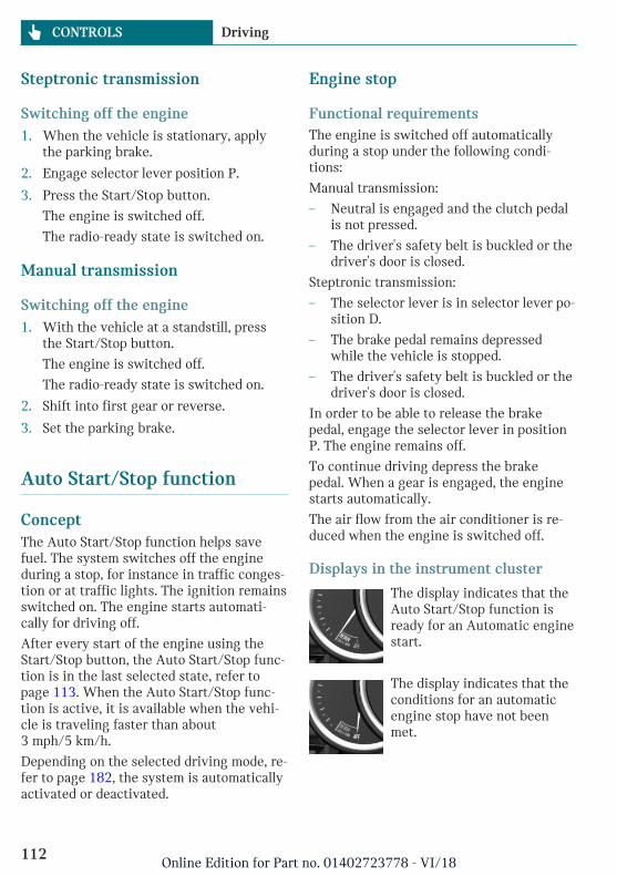
Steptronic transmission
Switching off the engine1. When the vehicle is stationary, apply
the parking brake.
2. Engage selector lever position P.
3. Press the Start/Stop button.
The engine is switched off.
The radio-ready state is switched on.
Manual transmission
Switching off the engine1. With the vehicle at a standstill, press
the Start/Stop button.
The engine is switched off.
The radio-ready state is switched on.
2. Shift into first gear or reverse.
3. Set the parking brake.
Auto Start/Stop function
ConceptThe Auto Start/Stop function helps savefuel. The system switches off the engineduring a stop, for instance in traffic conges-tion or at traffic lights. The ignition remainsswitched on. The engine starts automati-cally for driving off.
After every start of the engine using theStart/Stop button, the Auto Start/Stop func-tion is in the last selected state, refer topage 113. When the Auto Start/Stop func-tion is active, it is available when the vehi-cle is traveling faster than about3 mph/5 km/h.
Depending on the selected driving mode, re-fer to page 182, the system is automaticallyactivated or deactivated.
Engine stop
Functional requirementsThe engine is switched off automaticallyduring a stop under the following condi-tions:
Manual transmission:
– Neutral is engaged and the clutch pedalis not pressed.
– The driver's safety belt is buckled or thedriver's door is closed.
Steptronic transmission:
– The selector lever is in selector lever po-sition D.
– The brake pedal remains depressedwhile the vehicle is stopped.
– The driver's safety belt is buckled or thedriver's door is closed.
In order to be able to release the brakepedal, engage the selector lever in positionP. The engine remains off.
To continue driving depress the brakepedal. When a gear is engaged, the enginestarts automatically.
The air flow from the air conditioner is re-duced when the engine is switched off.
Displays in the instrument cluster
The display indicates that theAuto Start/Stop function isready for an Automatic enginestart.
The display indicates that theconditions for an automaticengine stop have not beenmet.
Seite 112
CONTROLS Driving
112Online Edition for Part no. 01402723778 - VI/18
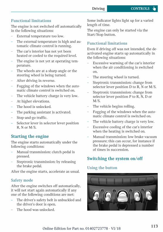
Functional limitationsThe engine is not switched off automaticallyin the following situations:
– External temperature too low.
– The external temperature is high and au-tomatic climate control is running.
– The car's interior has not yet beenheated or cooled to the required level.
– The engine is not yet at operating tem-perature.
– The wheels are at a sharp angle or thesteering wheel is being turned.
– After driving in reverse.
– Fogging of the windows when the auto-matic climate control is switched on.
– The vehicle battery charge is very low.
– At higher elevations.
– The hood is unlocked.
– The parking assistant is activated.
– Stop-and-go traffic.
– Selector lever in selector lever positionR, N or M/S.
Starting the engineThe engine starts automatically under thefollowing conditions:
– Manual transmission: clutch pedal ispressed.
– Steptronic transmission: by releasingthe brake pedal.
After the engine starts, accelerate as usual.
Safety modeAfter the engine switches off automatically,it will not start again automatically if anyone of the following conditions are met:
– The driver's safety belt is unbuckled andthe driver's door is open.
– The hood was unlocked.
Some indicator lights light up for a variedlength of time.
The engine can only be started via theStart/Stop button.
Functional limitationsEven if driving off was not intended, the de-activated engine starts up automatically inthe following situations:
– Excessive warming of the car's interiorwhen the air conditioning is switchedon.
– The steering wheel is turned.
– Steptronic transmission: change fromselector lever position D to R, N or M/S.
– Steptronic transmission: change fromselector lever position P to R, N, D orM/S.
– The vehicle begins rolling.
– Fogging of the windows when the auto-matic climate control is switched on.
– The vehicle battery charge is very low.
– Excessive cooling of the car's interiorwhen the heating is switched on.
– Manual transmission: low brake vacuumpressure; this can occur, for instance ifthe brake pedal is depressed a numberof times in succession.
Switching the system on/off
Using the button
Seite 113
Driving CONTROLS
113Online Edition for Part no. 01402723778 - VI/18
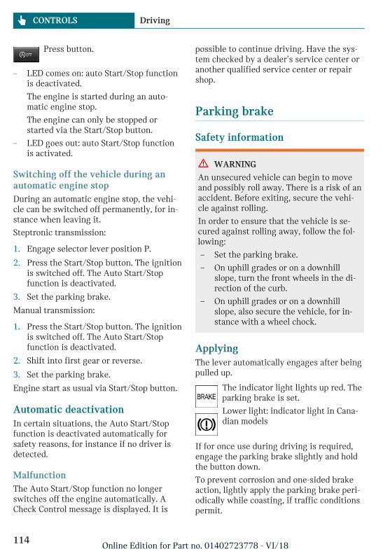
Press button.
– LED comes on: auto Start/Stop functionis deactivated.
The engine is started during an auto-matic engine stop.
The engine can only be stopped orstarted via the Start/Stop button.
– LED goes out: auto Start/Stop functionis activated.
Switching off the vehicle during anautomatic engine stopDuring an automatic engine stop, the vehi-cle can be switched off permanently, for in-stance when leaving it.
Steptronic transmission:
1. Engage selector lever position P.
2. Press the Start/Stop button. The ignitionis switched off. The Auto Start/Stopfunction is deactivated.
3. Set the parking brake.
Manual transmission:
1. Press the Start/Stop button. The ignitionis switched off. The Auto Start/Stopfunction is deactivated.
2. Shift into first gear or reverse.
3. Set the parking brake.
Engine start as usual via Start/Stop button.
Automatic deactivationIn certain situations, the Auto Start/Stopfunction is deactivated automatically forsafety reasons, for instance if no driver isdetected.
MalfunctionThe Auto Start/Stop function no longerswitches off the engine automatically. ACheck Control message is displayed. It is
possible to continue driving. Have the sys-tem checked by a dealer’s service center oranother qualified service center or repairshop.
Parking brake
Safety information
WARNING
An unsecured vehicle can begin to moveand possibly roll away. There is a risk of anaccident. Before exiting, secure the vehi-cle against rolling.
In order to ensure that the vehicle is se-cured against rolling away, follow the fol-lowing:
– Set the parking brake.
– On uphill grades or on a downhillslope, turn the front wheels in the di-rection of the curb.
– On uphill grades or on a downhillslope, also secure the vehicle, for in-stance with a wheel chock.
ApplyingThe lever automatically engages after beingpulled up.
The indicator light lights up red. Theparking brake is set.
Lower light: indicator light in Cana-dian models
If for once use during driving is required,engage the parking brake slightly and holdthe button down.
To prevent corrosion and one-sided brakeaction, lightly apply the parking brake peri-odically while coasting, if traffic conditionspermit.
Seite 114
CONTROLS Driving
114Online Edition for Part no. 01402723778 - VI/18
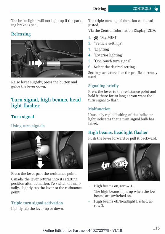
The brake lights will not light up if the park-ing brake is set.
Releasing
Raise lever slightly, press the button andguide the lever down.
Turn signal, high beams, head-light flasher
Turn signal
Using turn signals
Press the lever past the resistance point.
Canada: the lever returns into its startingposition after actuation. To switch off man-ually, slightly tap the lever to the resistancepoint.
Triple turn signal activationLightly tap the lever up or down.
The triple turn signal duration can be ad-justed.
Via the Central Information Display (CID):
1. "My MINI"
2. "Vehicle settings"
3. "Lighting"
4. "Exterior lighting"
5. "One-touch turn signal"
6. Select the desired setting.
Settings are stored for the profile currentlyused.
Signaling brieflyPress the lever to the resistance point andhold it there for as long as you want theturn signal to flash.
MalfunctionUnusually rapid flashing of the indicatorlight indicates that a turn signal bulb hasfailed.
High beams, headlight flasherPush the lever forward or pull it backward.
– High beams on, arrow 1.
The high beams light up when the lowbeams are switched on.
– High beams off/headlight flasher, ar-row 2.
Seite 115
Driving CONTROLS
115Online Edition for Part no. 01402723778 - VI/18
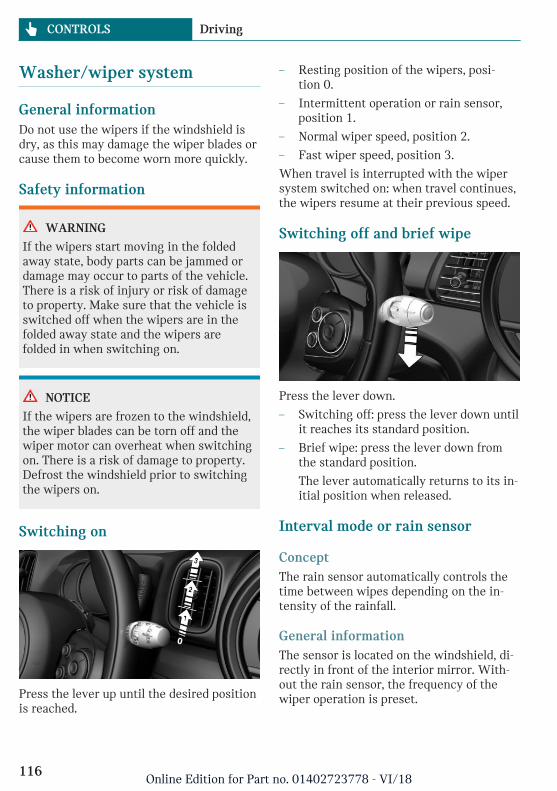
Washer/wiper system
General informationDo not use the wipers if the windshield isdry, as this may damage the wiper blades orcause them to become worn more quickly.
Safety information
WARNING
If the wipers start moving in the foldedaway state, body parts can be jammed ordamage may occur to parts of the vehicle.There is a risk of injury or risk of damageto property. Make sure that the vehicle isswitched off when the wipers are in thefolded away state and the wipers arefolded in when switching on.
NOTICE
If the wipers are frozen to the windshield,the wiper blades can be torn off and thewiper motor can overheat when switchingon. There is a risk of damage to property.Defrost the windshield prior to switchingthe wipers on.
Switching on
Press the lever up until the desired positionis reached.
– Resting position of the wipers, posi-tion 0.
– Intermittent operation or rain sensor,position 1.
– Normal wiper speed, position 2.
– Fast wiper speed, position 3.
When travel is interrupted with the wipersystem switched on: when travel continues,the wipers resume at their previous speed.
Switching off and brief wipe
Press the lever down.
– Switching off: press the lever down untilit reaches its standard position.
– Brief wipe: press the lever down fromthe standard position.
The lever automatically returns to its in-itial position when released.
Interval mode or rain sensor
ConceptThe rain sensor automatically controls thetime between wipes depending on the in-tensity of the rainfall.
General informationThe sensor is located on the windshield, di-rectly in front of the interior mirror. With-out the rain sensor, the frequency of thewiper operation is preset.
Seite 116
CONTROLS Driving
116Online Edition for Part no. 01402723778 - VI/18
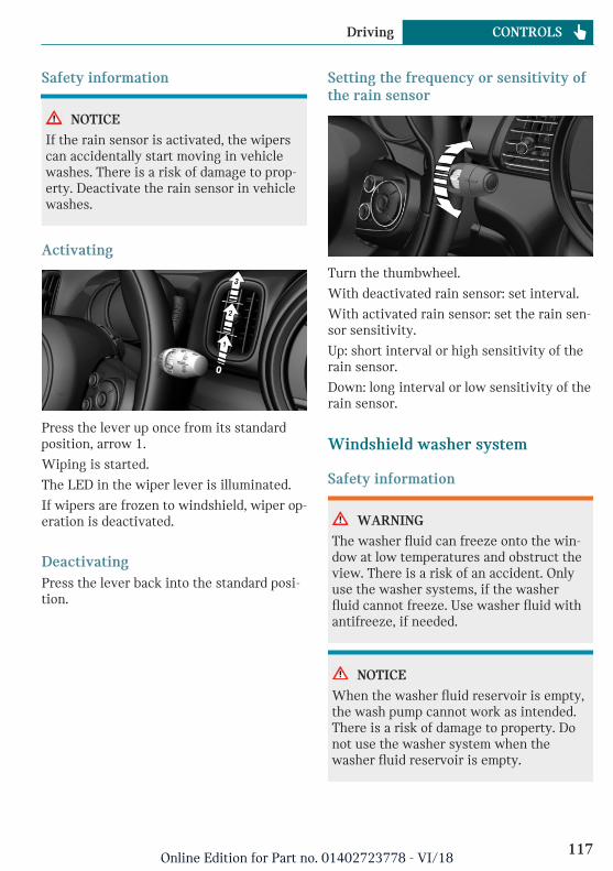
Safety information
NOTICE
If the rain sensor is activated, the wiperscan accidentally start moving in vehiclewashes. There is a risk of damage to prop-erty. Deactivate the rain sensor in vehiclewashes.
Activating
Press the lever up once from its standardposition, arrow 1.
Wiping is started.
The LED in the wiper lever is illuminated.
If wipers are frozen to windshield, wiper op-eration is deactivated.
DeactivatingPress the lever back into the standard posi-tion.
Setting the frequency or sensitivity ofthe rain sensor
Turn the thumbwheel.
With deactivated rain sensor: set interval.
With activated rain sensor: set the rain sen-sor sensitivity.
Up: short interval or high sensitivity of therain sensor.
Down: long interval or low sensitivity of therain sensor.
Windshield washer system
Safety information
WARNING
The washer fluid can freeze onto the win-dow at low temperatures and obstruct theview. There is a risk of an accident. Onlyuse the washer systems, if the washerfluid cannot freeze. Use washer fluid withantifreeze, if needed.
NOTICE
When the washer fluid reservoir is empty,the wash pump cannot work as intended.There is a risk of damage to property. Donot use the washer system when thewasher fluid reservoir is empty.
Seite 117
Driving CONTROLS
117Online Edition for Part no. 01402723778 - VI/18
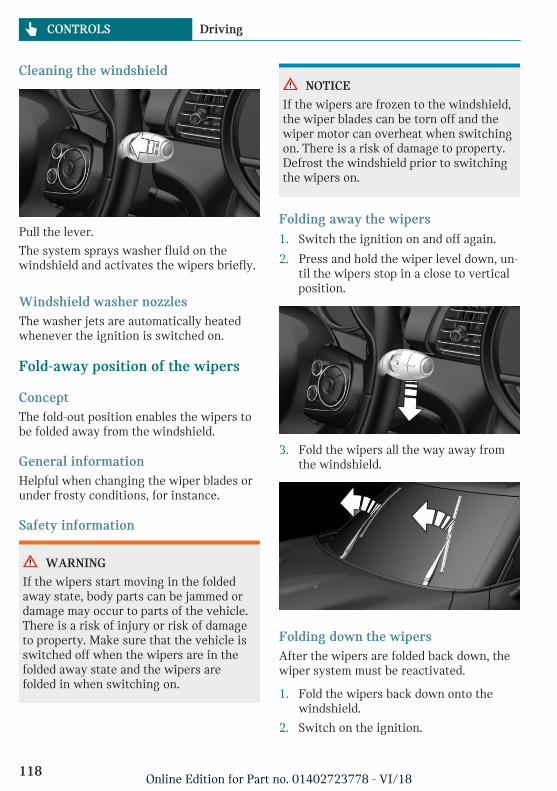
Cleaning the windshield
Pull the lever.
The system sprays washer fluid on thewindshield and activates the wipers briefly.
Windshield washer nozzlesThe washer jets are automatically heatedwhenever the ignition is switched on.
Fold-away position of the wipers
ConceptThe fold-out position enables the wipers tobe folded away from the windshield.
General informationHelpful when changing the wiper blades orunder frosty conditions, for instance.
Safety information
WARNING
If the wipers start moving in the foldedaway state, body parts can be jammed ordamage may occur to parts of the vehicle.There is a risk of injury or risk of damageto property. Make sure that the vehicle isswitched off when the wipers are in thefolded away state and the wipers arefolded in when switching on.
NOTICE
If the wipers are frozen to the windshield,the wiper blades can be torn off and thewiper motor can overheat when switchingon. There is a risk of damage to property.Defrost the windshield prior to switchingthe wipers on.
Folding away the wipers1. Switch the ignition on and off again.
2. Press and hold the wiper level down, un-til the wipers stop in a close to verticalposition.
3. Fold the wipers all the way away fromthe windshield.
Folding down the wipersAfter the wipers are folded back down, thewiper system must be reactivated.
1. Fold the wipers back down onto thewindshield.
2. Switch on the ignition.
Seite 118
CONTROLS Driving
118Online Edition for Part no. 01402723778 - VI/18
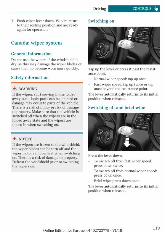
3. Push wiper lever down. Wipers returnto their resting position and are readyagain for operation.
Canada: wiper system
General informationDo not use the wipers if the windshield isdry, as this may damage the wiper blades orcause them to become worn more quickly.
Safety information
WARNING
If the wipers start moving in the foldedaway state, body parts can be jammed ordamage may occur to parts of the vehicle.There is a risk of injury or risk of damageto property. Make sure that the vehicle isswitched off when the wipers are in thefolded away state and the wipers arefolded in when switching on.
NOTICE
If the wipers are frozen to the windshield,the wiper blades can be torn off and thewiper motor can overheat when switchingon. There is a risk of damage to property.Defrost the windshield prior to switchingthe wipers on.
Switching on
Tap up the lever or press it past the resist-ance point.
– Normal wiper speed: tap up once.
– Fast wiper speed: tap up twice or taponce beyond the resistance point.
The lever automatically returns to its initialposition when released.
Switching off and brief wipe
Press the lever down.
– To switch off from fast wiper speed:press down twice.
– To switch off from normal wiper speed:press down once.
– Brief wipe: press down once.
The lever automatically returns to its initialposition when released.
Seite 119
Driving CONTROLS
119Online Edition for Part no. 01402723778 - VI/18
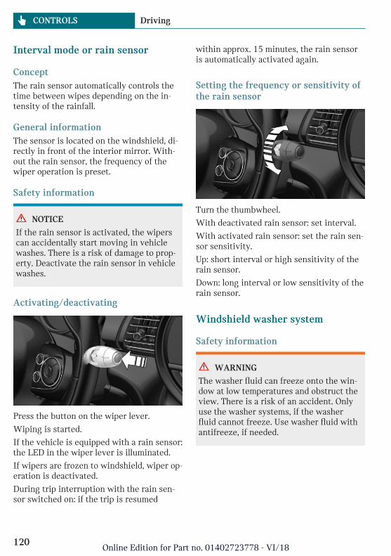
Interval mode or rain sensor
ConceptThe rain sensor automatically controls thetime between wipes depending on the in-tensity of the rainfall.
General informationThe sensor is located on the windshield, di-rectly in front of the interior mirror. With-out the rain sensor, the frequency of thewiper operation is preset.
Safety information
NOTICE
If the rain sensor is activated, the wiperscan accidentally start moving in vehiclewashes. There is a risk of damage to prop-erty. Deactivate the rain sensor in vehiclewashes.
Activating/deactivating
Press the button on the wiper lever.
Wiping is started.
If the vehicle is equipped with a rain sensor:the LED in the wiper lever is illuminated.
If wipers are frozen to windshield, wiper op-eration is deactivated.
During trip interruption with the rain sen-sor switched on: if the trip is resumed
within approx. 15 minutes, the rain sensoris automatically activated again.
Setting the frequency or sensitivity ofthe rain sensor
Turn the thumbwheel.
With deactivated rain sensor: set interval.
With activated rain sensor: set the rain sen-sor sensitivity.
Up: short interval or high sensitivity of therain sensor.
Down: long interval or low sensitivity of therain sensor.
Windshield washer system
Safety information
WARNING
The washer fluid can freeze onto the win-dow at low temperatures and obstruct theview. There is a risk of an accident. Onlyuse the washer systems, if the washerfluid cannot freeze. Use washer fluid withantifreeze, if needed.
Seite 120
CONTROLS Driving
120Online Edition for Part no. 01402723778 - VI/18
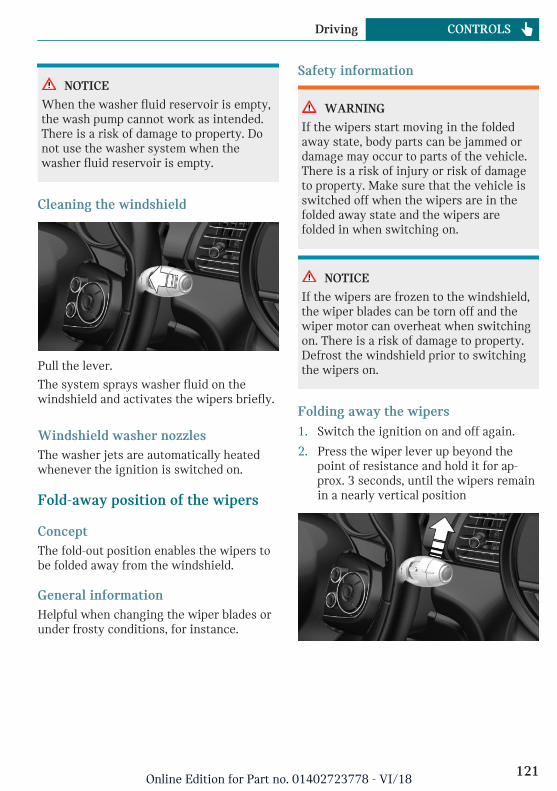
NOTICE
When the washer fluid reservoir is empty,the wash pump cannot work as intended.There is a risk of damage to property. Donot use the washer system when thewasher fluid reservoir is empty.
Cleaning the windshield
Pull the lever.
The system sprays washer fluid on thewindshield and activates the wipers briefly.
Windshield washer nozzlesThe washer jets are automatically heatedwhenever the ignition is switched on.
Fold-away position of the wipers
ConceptThe fold-out position enables the wipers tobe folded away from the windshield.
General informationHelpful when changing the wiper blades orunder frosty conditions, for instance.
Safety information
WARNING
If the wipers start moving in the foldedaway state, body parts can be jammed ordamage may occur to parts of the vehicle.There is a risk of injury or risk of damageto property. Make sure that the vehicle isswitched off when the wipers are in thefolded away state and the wipers arefolded in when switching on.
NOTICE
If the wipers are frozen to the windshield,the wiper blades can be torn off and thewiper motor can overheat when switchingon. There is a risk of damage to property.Defrost the windshield prior to switchingthe wipers on.
Folding away the wipers1. Switch the ignition on and off again.
2. Press the wiper lever up beyond thepoint of resistance and hold it for ap-prox. 3 seconds, until the wipers remainin a nearly vertical position
Seite 121
Driving CONTROLS
121Online Edition for Part no. 01402723778 - VI/18
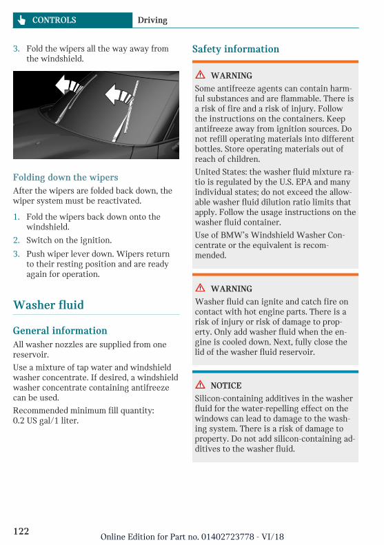
3. Fold the wipers all the way away fromthe windshield.
Folding down the wipersAfter the wipers are folded back down, thewiper system must be reactivated.
1. Fold the wipers back down onto thewindshield.
2. Switch on the ignition.
3. Push wiper lever down. Wipers returnto their resting position and are readyagain for operation.
Washer fluid
General informationAll washer nozzles are supplied from onereservoir.
Use a mixture of tap water and windshieldwasher concentrate. If desired, a windshieldwasher concentrate containing antifreezecan be used.
Recommended minimum fill quantity:0.2 US gal/1 liter.
Safety information
WARNING
Some antifreeze agents can contain harm-ful substances and are flammable. There isa risk of fire and a risk of injury. Followthe instructions on the containers. Keepantifreeze away from ignition sources. Donot refill operating materials into differentbottles. Store operating materials out ofreach of children.
United States: the washer fluid mixture ra-tio is regulated by the U.S. EPA and manyindividual states; do not exceed the allow-able washer fluid dilution ratio limits thatapply. Follow the usage instructions on thewasher fluid container.
Use of BMW’s Windshield Washer Con-centrate or the equivalent is recom-mended.
WARNING
Washer fluid can ignite and catch fire oncontact with hot engine parts. There is arisk of injury or risk of damage to prop-erty. Only add washer fluid when the en-gine is cooled down. Next, fully close thelid of the washer fluid reservoir.
NOTICE
Silicon-containing additives in the washerfluid for the water-repelling effect on thewindows can lead to damage to the wash-ing system. There is a risk of damage toproperty. Do not add silicon-containing ad-ditives to the washer fluid.
Seite 122
CONTROLS Driving
122Online Edition for Part no. 01402723778 - VI/18
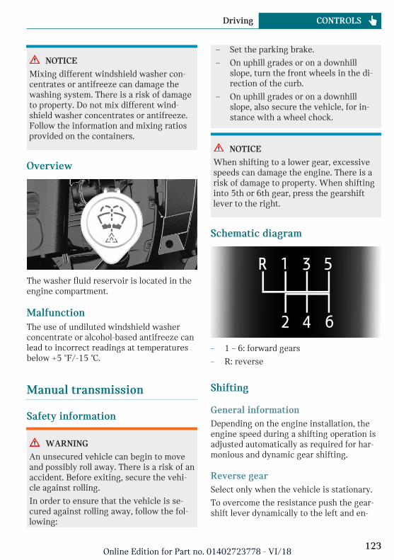
NOTICE
Mixing different windshield washer con-centrates or antifreeze can damage thewashing system. There is a risk of damageto property. Do not mix different wind-shield washer concentrates or antifreeze.Follow the information and mixing ratiosprovided on the containers.
Overview
The washer fluid reservoir is located in theengine compartment.
MalfunctionThe use of undiluted windshield washerconcentrate or alcohol-based antifreeze canlead to incorrect readings at temperaturesbelow +5 ℉/-15 ℃.
Manual transmission
Safety information
WARNING
An unsecured vehicle can begin to moveand possibly roll away. There is a risk of anaccident. Before exiting, secure the vehi-cle against rolling.
In order to ensure that the vehicle is se-cured against rolling away, follow the fol-lowing:
– Set the parking brake.
– On uphill grades or on a downhillslope, turn the front wheels in the di-rection of the curb.
– On uphill grades or on a downhillslope, also secure the vehicle, for in-stance with a wheel chock.
NOTICE
When shifting to a lower gear, excessivespeeds can damage the engine. There is arisk of damage to property. When shiftinginto 5th or 6th gear, press the gearshiftlever to the right.
Schematic diagram
– 1 – 6: forward gears
– R: reverse
Shifting
General informationDepending on the engine installation, theengine speed during a shifting operation isadjusted automatically as required for har-monious and dynamic gear shifting.
Reverse gearSelect only when the vehicle is stationary.
To overcome the resistance push the gear-shift lever dynamically to the left and en-
Seite 123
Driving CONTROLS
123Online Edition for Part no. 01402723778 - VI/18
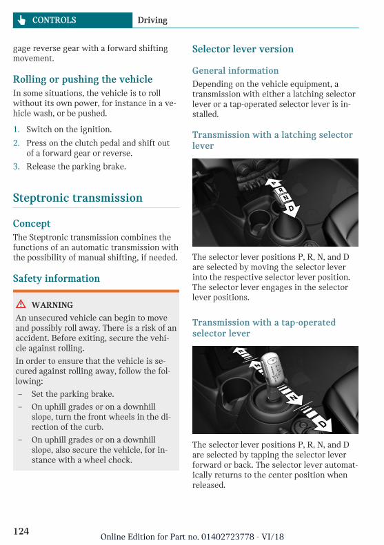
gage reverse gear with a forward shiftingmovement.
Rolling or pushing the vehicleIn some situations, the vehicle is to rollwithout its own power, for instance in a ve-hicle wash, or be pushed.
1. Switch on the ignition.
2. Press on the clutch pedal and shift outof a forward gear or reverse.
3. Release the parking brake.
Steptronic transmission
ConceptThe Steptronic transmission combines thefunctions of an automatic transmission withthe possibility of manual shifting, if needed.
Safety information
WARNING
An unsecured vehicle can begin to moveand possibly roll away. There is a risk of anaccident. Before exiting, secure the vehi-cle against rolling.
In order to ensure that the vehicle is se-cured against rolling away, follow the fol-lowing:
– Set the parking brake.
– On uphill grades or on a downhillslope, turn the front wheels in the di-rection of the curb.
– On uphill grades or on a downhillslope, also secure the vehicle, for in-stance with a wheel chock.
Selector lever version
General informationDepending on the vehicle equipment, atransmission with either a latching selectorlever or a tap-operated selector lever is in-stalled.
Transmission with a latching selectorlever
The selector lever positions P, R, N, and Dare selected by moving the selector leverinto the respective selector lever position.The selector lever engages in the selectorlever positions.
Transmission with a tap-operatedselector lever
The selector lever positions P, R, N, and Dare selected by tapping the selector leverforward or back. The selector lever automat-ically returns to the center position whenreleased.
Seite 124
CONTROLS Driving
124Online Edition for Part no. 01402723778 - VI/18
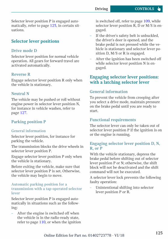
Selector lever position P is engaged auto-matically, refer to page 125, in certain sit-uations.
Selector lever positions
Drive mode DSelector lever position for normal vehicleoperation. All gears for forward travel areactivated automatically.
Reverse REngage selector lever position R only whenthe vehicle is stationary.
Neutral NThe vehicle may be pushed or roll withoutengine power in selector lever position N,for instance in vehicle washes, refer topage 127.
Parking position P
General information
Selector lever position, for instance forparking the vehicle.
The transmission blocks the drive wheels inselector lever position P.
Engage selector lever position P only whenthe vehicle is stationary.
Before exiting the vehicle, make sure thatselector lever position P is set. Otherwise,the vehicle may begin to move.
Automatic parking position for atransmission with a tap-operated selectorlever
Selector lever position P is engaged auto-matically in situations such as the follow-ing:
– After the engine is switched off whenthe vehicle is in the radio-ready state,refer to page 110, or when the ignition
is switched off, refer to page 109, whileselector lever position R, D or M/S is en-gaged.
– If the driver's safety belt is unbuckled,the driver's door is opened, and thebrake pedal is not pressed while the ve-hicle is stationary and selector lever po-sition D, M/S or R is engaged.
– After the ignition has been switched offwhile selector lever position N is en-gaged.
Engaging selector lever positions:with a latching selector lever
General informationTo prevent the vehicle from creeping afteryou select a drive mode, maintain pressureon the brake pedal until you are ready tostart.
Functional requirementsThe selector lever can only be taken out ofselector lever position P if the ignition is onor the engine is running.
Engaging selector lever position D, N,R, or PWith the vehicle stationary, depress thebrake pedal before shifting out of selectorlever position P or N; otherwise, the shiftblock will not be deactivated and the shiftcommand will not be executed.
A selector lever lock prevents the followingfaulty operation:
– Unintentional shifting into selectorlever position P or R.
Seite 125
Driving CONTROLS
125Online Edition for Part no. 01402723778 - VI/18
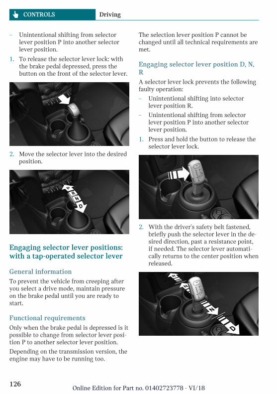
– Unintentional shifting from selectorlever position P into another selectorlever position.
1. To release the selector lever lock: withthe brake pedal depressed, press thebutton on the front of the selector lever.
2. Move the selector lever into the desiredposition.
Engaging selector lever positions:with a tap-operated selector lever
General informationTo prevent the vehicle from creeping afteryou select a drive mode, maintain pressureon the brake pedal until you are ready tostart.
Functional requirementsOnly when the brake pedal is depressed is itpossible to change from selector lever posi-tion P to another selector lever position.
Depending on the transmission version, theengine may have to be running too.
The selection lever position P cannot bechanged until all technical requirements aremet.
Engaging selector lever position D, N,RA selector lever lock prevents the followingfaulty operation:
– Unintentional shifting into selectorlever position R.
– Unintentional shifting from selectorlever position P into another selectorlever position.
1. Press and hold the button to release theselector lever lock.
2. With the driver's safety belt fastened,briefly push the selector lever in the de-sired direction, past a resistance point,if needed. The selector lever automati-cally returns to the center position whenreleased.
Seite 126
CONTROLS Driving
126Online Edition for Part no. 01402723778 - VI/18
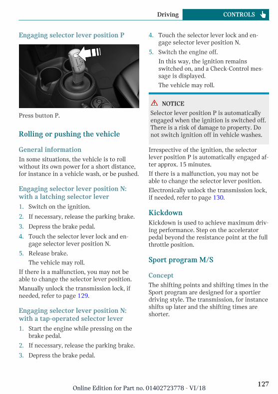
Engaging selector lever position P
Press button P.
Rolling or pushing the vehicle
General informationIn some situations, the vehicle is to rollwithout its own power for a short distance,for instance in a vehicle wash, or be pushed.
Engaging selector lever position N:with a latching selector lever1. Switch on the ignition.
2. If necessary, release the parking brake.
3. Depress the brake pedal.
4. Touch the selector lever lock and en-gage selector lever position N.
5. Release brake.
The vehicle may roll.
If there is a malfunction, you may not beable to change the selector lever position.
Manually unlock the transmission lock, ifneeded, refer to page 129.
Engaging selector lever position N:with a tap-operated selector lever1. Start the engine while pressing on the
brake pedal.
2. If necessary, release the parking brake.
3. Depress the brake pedal.
4. Touch the selector lever lock and en-gage selector lever position N.
5. Switch the engine off.
In this way, the ignition remainsswitched on, and a Check-Control mes-sage is displayed.
The vehicle may roll.
NOTICE
Selector lever position P is automaticallyengaged when the ignition is switched off.There is a risk of damage to property. Donot switch ignition off in vehicle washes.
Irrespective of the ignition, the selectorlever position P is automatically engaged af-ter approx. 15 minutes.
If there is a malfunction, you may not beable to change the selector lever position.
Electronically unlock the transmission lock,if needed, refer to page 130.
KickdownKickdown is used to achieve maximum driv-ing performance. Step on the acceleratorpedal beyond the resistance point at the fullthrottle position.
Sport program M/S
ConceptThe shifting points and shifting times in theSport program are designed for a sportierdriving style. The transmission, for instanceshifts up later and the shifting times areshorter.
Seite 127
Driving CONTROLS
127Online Edition for Part no. 01402723778 - VI/18
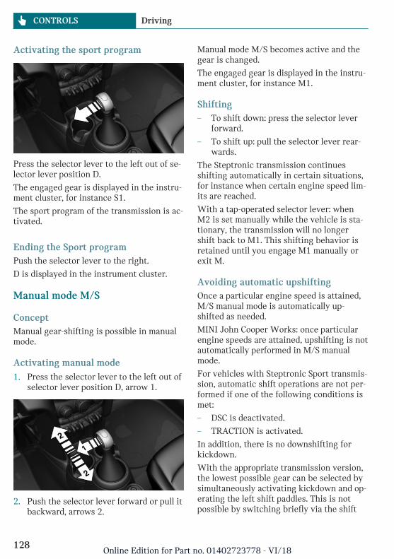
Activating the sport program
Press the selector lever to the left out of se-lector lever position D.
The engaged gear is displayed in the instru-ment cluster, for instance S1.
The sport program of the transmission is ac-tivated.
Ending the Sport programPush the selector lever to the right.
D is displayed in the instrument cluster.
Manual mode M/S
ConceptManual gear-shifting is possible in manualmode.
Activating manual mode1. Press the selector lever to the left out of
selector lever position D, arrow 1.
2. Push the selector lever forward or pull itbackward, arrows 2.
Manual mode M/S becomes active and thegear is changed.
The engaged gear is displayed in the instru-ment cluster, for instance M1.
Shifting– To shift down: press the selector lever
forward.
– To shift up: pull the selector lever rear-wards.
The Steptronic transmission continuesshifting automatically in certain situations,for instance when certain engine speed lim-its are reached.
With a tap-operated selector lever: whenM2 is set manually while the vehicle is sta-tionary, the transmission will no longershift back to M1. This shifting behavior isretained until you engage M1 manually orexit M.
Avoiding automatic upshiftingOnce a particular engine speed is attained,M/S manual mode is automatically up-shifted as needed.
MINI John Cooper Works: once particularengine speeds are attained, upshifting is notautomatically performed in M/S manualmode.
For vehicles with Steptronic Sport transmis-sion, automatic shift operations are not per-formed if one of the following conditions ismet:
– DSC is deactivated.
– TRACTION is activated.
In addition, there is no downshifting forkickdown.
With the appropriate transmission version,the lowest possible gear can be selected bysimultaneously activating kickdown and op-erating the left shift paddles. This is notpossible by switching briefly via the shift
Seite 128
CONTROLS Driving
128Online Edition for Part no. 01402723778 - VI/18
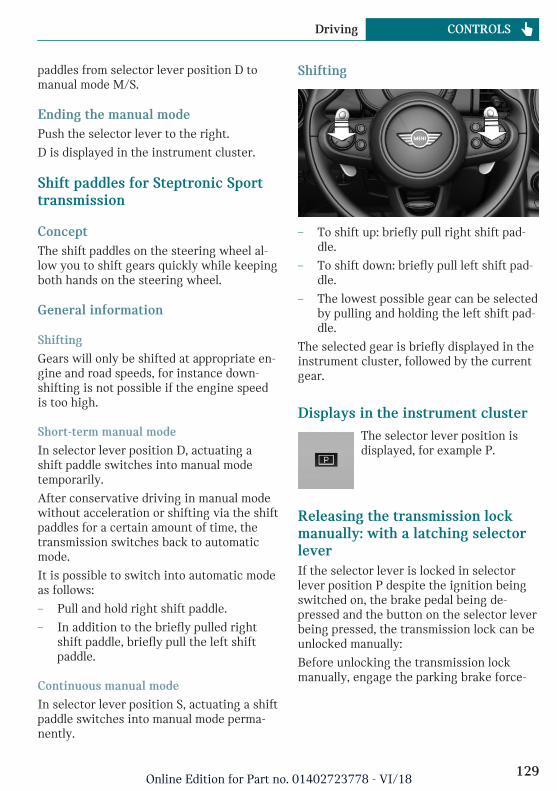
paddles from selector lever position D tomanual mode M/S.
Ending the manual modePush the selector lever to the right.
D is displayed in the instrument cluster.
Shift paddles for Steptronic Sporttransmission
ConceptThe shift paddles on the steering wheel al-low you to shift gears quickly while keepingboth hands on the steering wheel.
General information
Shifting
Gears will only be shifted at appropriate en-gine and road speeds, for instance down-shifting is not possible if the engine speedis too high.
Short-term manual mode
In selector lever position D, actuating ashift paddle switches into manual modetemporarily.
After conservative driving in manual modewithout acceleration or shifting via the shiftpaddles for a certain amount of time, thetransmission switches back to automaticmode.
It is possible to switch into automatic modeas follows:
– Pull and hold right shift paddle.
– In addition to the briefly pulled rightshift paddle, briefly pull the left shiftpaddle.
Continuous manual mode
In selector lever position S, actuating a shiftpaddle switches into manual mode perma-nently.
Shifting
– To shift up: briefly pull right shift pad-dle.
– To shift down: briefly pull left shift pad-dle.
– The lowest possible gear can be selectedby pulling and holding the left shift pad-dle.
The selected gear is briefly displayed in theinstrument cluster, followed by the currentgear.
Displays in the instrument clusterThe selector lever position isdisplayed, for example P.
Releasing the transmission lockmanually: with a latching selectorleverIf the selector lever is locked in selectorlever position P despite the ignition beingswitched on, the brake pedal being de-pressed and the button on the selector leverbeing pressed, the transmission lock can beunlocked manually:
Before unlocking the transmission lockmanually, engage the parking brake force-
Seite 129
Driving CONTROLS
129Online Edition for Part no. 01402723778 - VI/18
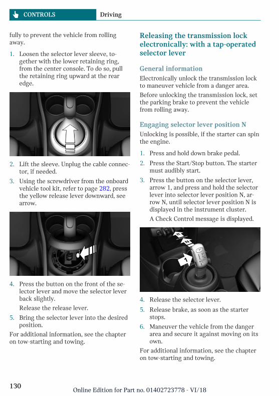
fully to prevent the vehicle from rollingaway.
1. Loosen the selector lever sleeve, to-gether with the lower retaining ring,from the center console. To do so, pullthe retaining ring upward at the rearedge.
2. Lift the sleeve. Unplug the cable connec-tor, if needed.
3. Using the screwdriver from the onboardvehicle tool kit, refer to page 282, pressthe yellow release lever downward, seearrow.
4. Press the button on the front of the se-lector lever and move the selector leverback slightly.
Release the release lever.
5. Bring the selector lever into the desiredposition.
For additional information, see the chapteron tow-starting and towing.
Releasing the transmission lockelectronically: with a tap-operatedselector lever
General informationElectronically unlock the transmission lockto maneuver vehicle from a danger area.
Before unlocking the transmission lock, setthe parking brake to prevent the vehiclefrom rolling away.
Engaging selector lever position NUnlocking is possible, if the starter can spinthe engine.
1. Press and hold down brake pedal.
2. Press the Start/Stop button. The startermust audibly start.
3. Press the button on the selector lever,arrow 1, and press and hold the selectorlever into selector lever position N, ar-row N, until selector lever position N isdisplayed in the instrument cluster.
A Check Control message is displayed.
4. Release the selector lever.
5. Release brake, as soon as the starterstops.
6. Maneuver the vehicle from the dangerarea and secure it against moving on itsown.
For additional information, see the chapteron tow-starting and towing.
Seite 130
CONTROLS Driving
130Online Edition for Part no. 01402723778 - VI/18
Steptronic Sport transmission:Launch Control
ConceptLaunch Control enables optimum accelera-tion on surfaces with good traction underdry surrounding conditions.
General informationThe use of Launch Control causes prema-ture component wear since this functionrepresents a very heavy load for the vehicle.
Do not use Launch Control during thebreak-in, refer to page 232, period.
To start with Launch Control do not steerthe steering wheel.
Functional requirementsLaunch Control is available as soon as theengine and transmission are at operatingtemperature.
Depending on the external temperature anddriving style, the engine and transmissionrequire an interrupted trip of up to30 miles/50 km in order to reach the oper-ating temperature needed for Launch Con-trol.
Start with launch controlWhile the engine is running:
1. Press button and select SPORTwith the MINI Driving Modes switch.
The instrument cluster displays TRAC-TION in combination with SPORT. TheDSC OFF indicator light lights up.
2. Engage selector lever position S.
3. With the left foot, forcefully press downon the brake.
4. Step on the accelerator pedal beyond theresistance point at the full throttle posi-tion, kickdown.
A flag symbol is displayed in the instru-ment cluster.
5. The starting engine speed adjusts.Within 3 seconds, release the brake.
Repeated use during a tripAfter Launch Control has been used, thetransmission must cool down for approx.5 minutes before Launch Control can beused again.
After using Launch ControlTo increase vehicle stability, activate DSCDynamic Stability Control again.
System limitsAn experienced driver may be able to ach-ieve better acceleration values in DSC OFFmode.
Seite 131
Driving CONTROLS
131Online Edition for Part no. 01402723778 - VI/18
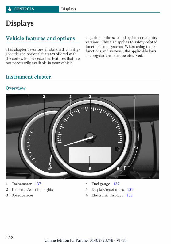
Displays
Vehicle features and options
This chapter describes all standard, country-specific and optional features offered withthe series. It also describes features that arenot necessarily available in your vehicle,
e. g., due to the selected options or countryversions. This also applies to safety-relatedfunctions and systems. When using thesefunctions and systems, the applicable lawsand regulations must be observed.
Instrument cluster
Overview
1 Tachometer 137
2 Indicator/warning lights
3 Speedometer
4 Fuel gauge 137
5 Display/reset miles 137
6 Electronic displays 133
Seite 132
CONTROLS Displays
132Online Edition for Part no. 01402723778 - VI/18
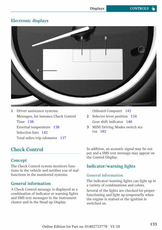
Electronic displays
1 Driver assistance systems
Messages, for instance Check Control
Time 138
External temperature 138
Selection lists 142
Total miles/trip odometer 137
Onboard Computer 142
2 Selector lever position 124
Gear shift indicator 140
3 MINI Driving Modes switch sta-tus 182
Check Control
ConceptThe Check Control system monitors func-tions in the vehicle and notifies you of mal-functions in the monitored systems.
General informationA Check Control message is displayed as acombination of indicator or warning lightsand SMS text messages in the instrumentcluster and in the Head-up Display.
In addition, an acoustic signal may be out-put and a SMS text message may appear onthe Control Display.
Indicator/warning lights
General informationThe indicator/warning lights can light up ina variety of combinations and colors.
Several of the lights are checked for properfunctioning and light up temporarily whenthe engine is started or the ignition isswitched on.
Seite 133
Displays CONTROLS
133Online Edition for Part no. 01402723778 - VI/18
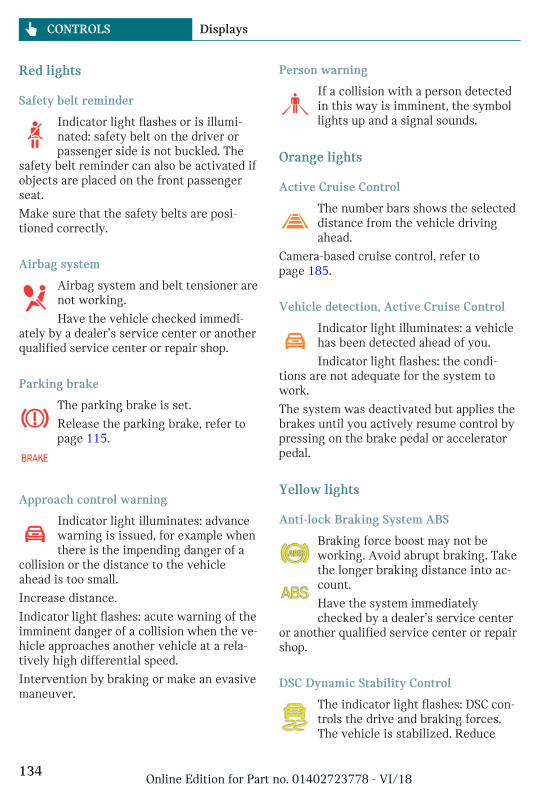
Red lights
Safety belt reminder
Indicator light flashes or is illumi-nated: safety belt on the driver orpassenger side is not buckled. The
safety belt reminder can also be activated ifobjects are placed on the front passengerseat.
Make sure that the safety belts are posi-tioned correctly.
Airbag system
Airbag system and belt tensioner arenot working.
Have the vehicle checked immedi-ately by a dealer’s service center or anotherqualified service center or repair shop.
Parking brake
The parking brake is set.
Release the parking brake, refer topage 115.
Approach control warning
Indicator light illuminates: advancewarning is issued, for example whenthere is the impending danger of a
collision or the distance to the vehicleahead is too small.
Increase distance.
Indicator light flashes: acute warning of theimminent danger of a collision when the ve-hicle approaches another vehicle at a rela-tively high differential speed.
Intervention by braking or make an evasivemaneuver.
Person warning
If a collision with a person detectedin this way is imminent, the symbollights up and a signal sounds.
Orange lights
Active Cruise Control
The number bars shows the selecteddistance from the vehicle drivingahead.
Camera-based cruise control, refer topage 185.
Vehicle detection, Active Cruise Control
Indicator light illuminates: a vehiclehas been detected ahead of you.
Indicator light flashes: the condi-tions are not adequate for the system towork.
The system was deactivated but applies thebrakes until you actively resume control bypressing on the brake pedal or acceleratorpedal.
Yellow lights
Anti-lock Braking System ABS
Braking force boost may not beworking. Avoid abrupt braking. Takethe longer braking distance into ac-count.
Have the system immediatelychecked by a dealer’s service center
or another qualified service center or repairshop.
DSC Dynamic Stability Control
The indicator light flashes: DSC con-trols the drive and braking forces.The vehicle is stabilized. Reduce
Seite 134
CONTROLS Displays
134Online Edition for Part no. 01402723778 - VI/18
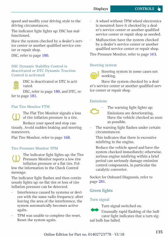
speed and modify your driving style to thedriving circumstances.
The indicator light lights up: DSC has mal-functioned.
Have the system checked by a dealer’s serv-ice center or another qualified service cen-ter or repair shop.
DSC, refer to page 180.
DSC Dynamic Stability Control isdeactivated or DTC Dynamic TractionControl is activated
DSC is deactivated or DTC is acti-vated.
DSC, refer to page 180, and DTC, re-fer to page 181.
Flat Tire Monitor FTM
The Flat Tire Monitor signals a lossof tire inflation pressure in a tire.
Reduce your speed and stop cau-tiously. Avoid sudden braking and steeringmaneuvers.
Flat Tire Monitor, refer to page 168.
Tire Pressure Monitor TPM
The indicator light lights up: the TirePressure Monitor reports a low tireinflation pressure or a flat tire. Fol-
low the information in the Check Controlmessage.
The indicator light flashes and then contin-uously lights up: no flat tire or loss of tireinflation pressure can be detected.
– Interference caused by systems or devi-ces with the same radio frequency: afterleaving the area of the interference, thesystem automatically becomes activeagain.
– TPM was unable to complete the reset.Reset the system again.
– A wheel without TPM wheel electronicsis mounted: have it checked by a deal-er’s service center or another qualifiedservice center or repair shop as needed.
– Malfunction: have the system checkedby a dealer’s service center or anotherqualified service center or repair shop.
Tire Pressure Monitor, refer to page 163.
Steering system
Steering system in some cases notworking.
Have the system checked by a deal-er’s service center or another qualified serv-ice center or repair shop.
Emissions
– The warning light lights up:
Emissions are deteriorating.Have the vehicle checked as soonas possible.
– The warning light flashes under certaincircumstances:
This indicates that there is excessivemisfiring in the engine.
Reduce the vehicle speed and have thesystem checked immediately; otherwise,serious engine misfiring within a briefperiod can seriously damage emissioncontrol components, in particular thecatalytic converter.
Socket for Onboard Diagnosis, refer topage 281.
Green lights
Turn signal
Turn signal switched on.
Unusually rapid flashing of the indi-cator light indicates that a turn sig-
nal bulb has failed.
Seite 135
Displays CONTROLS
135Online Edition for Part no. 01402723778 - VI/18
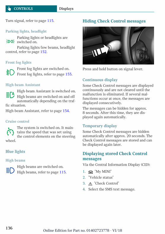
Turn signal, refer to page 115.
Parking lights, headlight
Parking lights or headlights areswitched on.
Parking lights/low beams, headlightcontrol, refer to page 152.
Front fog lights
Front fog lights are switched on.
Front fog lights, refer to page 155.
High-beam Assistant
High-beam Assistant is switched on.
High beams are switched on and offautomatically depending on the traf-
fic situation.
High-beam Assistant, refer to page 154.
Cruise control
The system is switched on. It main-tains the speed that was set usingthe control elements on the steering
wheel.
Blue lights
High beams
High beams are switched on.
High beams, refer to page 115.
Hiding Check Control messages
Press and hold button on signal lever.
Continuous displaySome Check Control messages are displayedcontinuously and are not cleared until themalfunction is eliminated. If several mal-functions occur at once, the messages aredisplayed consecutively.
The messages can be hidden for approx.8 seconds. After this time, they are dis-played again automatically.
Temporary displaySome Check Control messages are hiddenautomatically after approx. 20 seconds. TheCheck Control messages are stored and canbe displayed again later.
Displaying stored Check ControlmessagesVia the Central Information Display (CID):
1. "My MINI"
2. "Vehicle status"
3. "Check Control"
4. Select the SMS text message.
Seite 136
CONTROLS Displays
136Online Edition for Part no. 01402723778 - VI/18
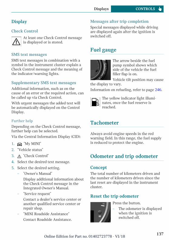
Display
Check Control
At least one Check Control messageis displayed or is stored.
SMS text messagesSMS text messages in combination with asymbol in the instrument cluster explain aCheck Control message and the meaning ofthe indicator/warning lights.
Supplementary SMS text messagesAdditional information, such as on thecause of an error or the required action, canbe called up via Check Control.
With urgent messages the added text willbe automatically displayed on the ControlDisplay.
Further help
Depending on the Check Control message,further help can be selected.
Via the Central Information Display (CID):
1. "My MINI"
2. "Vehicle status"
3. "Check Control"
4. Select the desired text message.
5. Select the desired setting.
– "Owner's Manual"
Display additional information aboutthe Check Control message in theIntegrated Owner's Manual.
– "Service request"
Contact a dealer’s service center oranother qualified service center orrepair shop.
– "MINI Roadside Assistance"
Contact Roadside Assistance.
Messages after trip completionSpecial messages displayed while drivingare displayed again after the ignition isswitched off.
Fuel gauge
The arrow beside the fuelpump symbol shows whichside of the vehicle the fuelfiller flap is on.
Vehicle tilt position may causethe display to vary.
Information on refueling, refer to page 246.
The yellow indicator light illumi-nates, once the fuel reserve isreached.
Tachometer
Always avoid engine speeds in the redwarning field. In this range, the fuel supplyis reduced to protect the engine.
Odometer and trip odometer
ConceptThe total number of kilometers driven andthe number of kilometers driven since thelast reset are displayed in the instrumentcluster.
Reset the trip odometerPress the button.
– The odometer is displayedwhen the ignition isswitched off.
Seite 137
Displays CONTROLS
137Online Edition for Part no. 01402723778 - VI/18
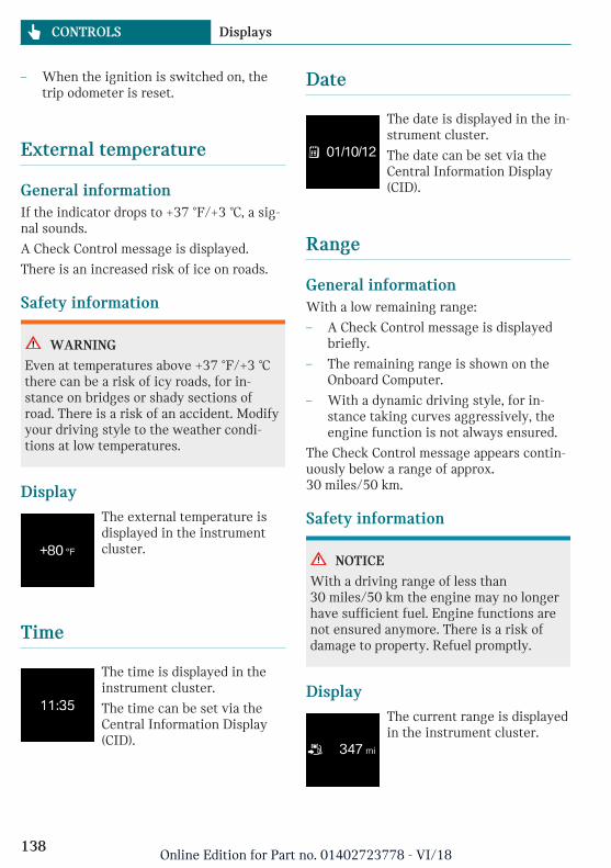
– When the ignition is switched on, thetrip odometer is reset.
External temperature
General informationIf the indicator drops to +37 ℉/+3 ℃, a sig-nal sounds.
A Check Control message is displayed.
There is an increased risk of ice on roads.
Safety information
WARNING
Even at temperatures above +37 ℉/+3 ℃there can be a risk of icy roads, for in-stance on bridges or shady sections ofroad. There is a risk of an accident. Modifyyour driving style to the weather condi-tions at low temperatures.
DisplayThe external temperature isdisplayed in the instrumentcluster.
Time
The time is displayed in theinstrument cluster.
The time can be set via theCentral Information Display(CID).
Date
The date is displayed in the in-strument cluster.
The date can be set via theCentral Information Display(CID).
Range
General informationWith a low remaining range:
– A Check Control message is displayedbriefly.
– The remaining range is shown on theOnboard Computer.
– With a dynamic driving style, for in-stance taking curves aggressively, theengine function is not always ensured.
The Check Control message appears contin-uously below a range of approx.30 miles/50 km.
Safety information
NOTICE
With a driving range of less than30 miles/50 km the engine may no longerhave sufficient fuel. Engine functions arenot ensured anymore. There is a risk ofdamage to property. Refuel promptly.
DisplayThe current range is displayedin the instrument cluster.
Seite 138
CONTROLS Displays
138Online Edition for Part no. 01402723778 - VI/18
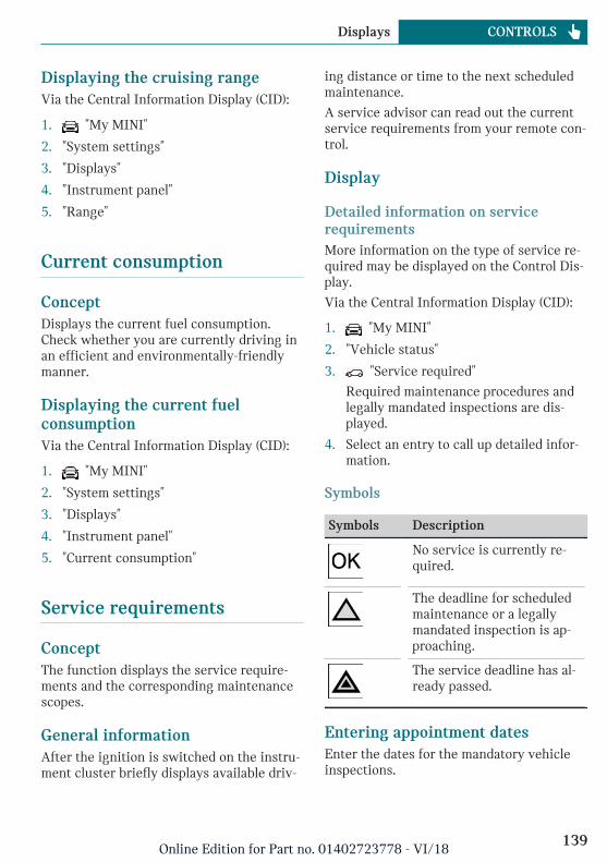
Displaying the cruising rangeVia the Central Information Display (CID):
1. "My MINI"
2. "System settings"
3. "Displays"
4. "Instrument panel"
5. "Range"
Current consumption
ConceptDisplays the current fuel consumption.Check whether you are currently driving inan efficient and environmentally-friendlymanner.
Displaying the current fuelconsumptionVia the Central Information Display (CID):
1. "My MINI"
2. "System settings"
3. "Displays"
4. "Instrument panel"
5. "Current consumption"
Service requirements
ConceptThe function displays the service require-ments and the corresponding maintenancescopes.
General informationAfter the ignition is switched on the instru-ment cluster briefly displays available driv-
ing distance or time to the next scheduledmaintenance.
A service advisor can read out the currentservice requirements from your remote con-trol.
Display
Detailed information on servicerequirementsMore information on the type of service re-quired may be displayed on the Control Dis-play.
Via the Central Information Display (CID):
1. "My MINI"
2. "Vehicle status"
3. "Service required"
Required maintenance procedures andlegally mandated inspections are dis-played.
4. Select an entry to call up detailed infor-mation.
Symbols
Symbols Description
No service is currently re-quired.
The deadline for scheduledmaintenance or a legallymandated inspection is ap-proaching.
The service deadline has al-ready passed.
Entering appointment datesEnter the dates for the mandatory vehicleinspections.
Seite 139
Displays CONTROLS
139Online Edition for Part no. 01402723778 - VI/18
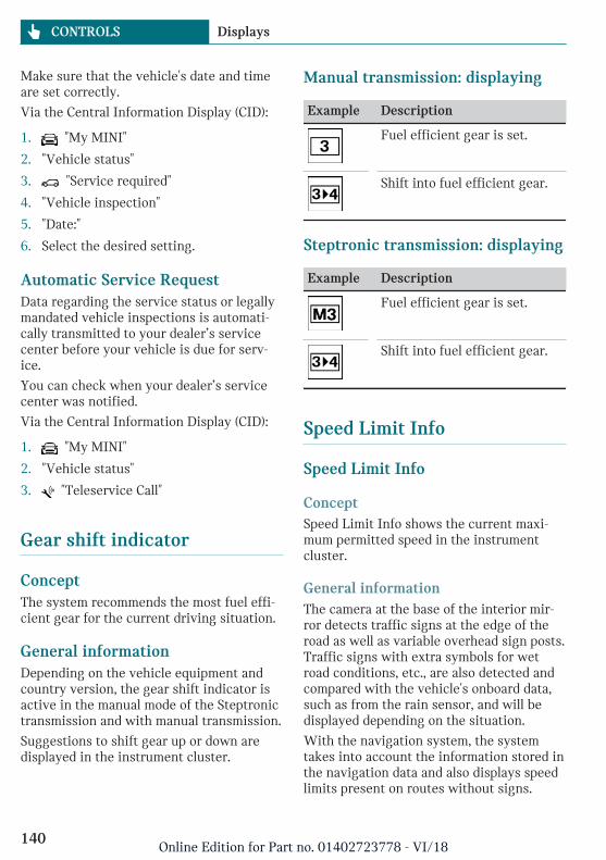
Make sure that the vehicle's date and timeare set correctly.
Via the Central Information Display (CID):
1. "My MINI"
2. "Vehicle status"
3. "Service required"
4. "Vehicle inspection"
5. "Date:"
6. Select the desired setting.
Automatic Service RequestData regarding the service status or legallymandated vehicle inspections is automati-cally transmitted to your dealer’s servicecenter before your vehicle is due for serv-ice.
You can check when your dealer’s servicecenter was notified.
Via the Central Information Display (CID):
1. "My MINI"
2. "Vehicle status"
3. "Teleservice Call"
Gear shift indicator
ConceptThe system recommends the most fuel effi-cient gear for the current driving situation.
General informationDepending on the vehicle equipment andcountry version, the gear shift indicator isactive in the manual mode of the Steptronictransmission and with manual transmission.
Suggestions to shift gear up or down aredisplayed in the instrument cluster.
Manual transmission: displaying
Example Description
Fuel efficient gear is set.
Shift into fuel efficient gear.
Steptronic transmission: displaying
Example Description
Fuel efficient gear is set.
Shift into fuel efficient gear.
Speed Limit Info
Speed Limit Info
ConceptSpeed Limit Info shows the current maxi-mum permitted speed in the instrumentcluster.
General informationThe camera at the base of the interior mir-ror detects traffic signs at the edge of theroad as well as variable overhead sign posts.Traffic signs with extra symbols for wetroad conditions, etc., are also detected andcompared with the vehicle's onboard data,such as from the rain sensor, and will bedisplayed depending on the situation.
With the navigation system, the systemtakes into account the information stored inthe navigation data and also displays speedlimits present on routes without signs.
Seite 140
CONTROLS Displays
140Online Edition for Part no. 01402723778 - VI/18
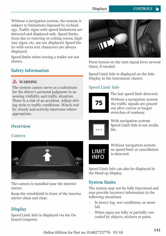
Without a navigation system, the system issubject to limitations imposed by technol-ogy. Traffic signs with speed limitations aredetected and displayed only. Speed limita-tions due to entering or exiting towns, high-way signs, etc. are not displayed. Speed lim-its with extra text characters are alwaysdisplayed.
Speed limits when towing a trailer are notshown.
Safety information
WARNING
The system cannot serve as a substitutefor the driver’s personal judgment in as-sessing visibility and traffic situation.There is a risk of an accident. Adjust driv-ing style to traffic conditions. Watch traf-fic closely and actively intervene whereappropriate.
Overview
Camera
The camera is installed near the interiormirror.
Keep the windshield in front of the interiormirror clean and clear.
DisplaySpeed Limit Info is displayed via the On-board Computer.
Press button on the turn signal lever severaltimes, if needed.
Speed Limit Info is displayed on the InfoDisplay in the instrument cluster.
Speed Limit Info
The last speed limit detected.
Without a navigation systemthe traffic signals are grayedout after curves or longerstretches of roadway.
With navigation system:Speed Limit Info is not availa-ble.
Without navigation system:no speed limit or cancellationis detected.
Speed Limit Info can also be displayed inthe Head-up Display.
System limitsThe system may not be fully functional andmay provide incorrect information in thefollowing situations:
– In heavy fog, wet conditions, or snow-fall.
– When signs are fully or partially con-cealed by objects, stickers or paint.
Seite 141
Displays CONTROLS
141Online Edition for Part no. 01402723778 - VI/18
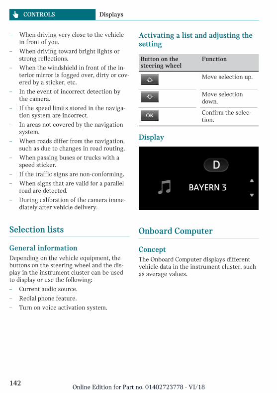
– When driving very close to the vehiclein front of you.
– When driving toward bright lights orstrong reflections.
– When the windshield in front of the in-terior mirror is fogged over, dirty or cov-ered by a sticker, etc.
– In the event of incorrect detection bythe camera.
– If the speed limits stored in the naviga-tion system are incorrect.
– In areas not covered by the navigationsystem.
– When roads differ from the navigation,such as due to changes in road routing.
– When passing buses or trucks with aspeed sticker.
– If the traffic signs are non-conforming.
– When signs that are valid for a parallelroad are detected.
– During calibration of the camera imme-diately after vehicle delivery.
Selection lists
General informationDepending on the vehicle equipment, thebuttons on the steering wheel and the dis-play in the instrument cluster can be usedto display or use the following:
– Current audio source.
– Redial phone feature.
– Turn on voice activation system.
Activating a list and adjusting thesetting
Button on thesteering wheel
Function
Move selection up.
Move selectiondown.
Confirm the selec-tion.
Display
Onboard Computer
ConceptThe Onboard Computer displays differentvehicle data in the instrument cluster, suchas average values.
Seite 142
CONTROLS Displays
142Online Edition for Part no. 01402723778 - VI/18
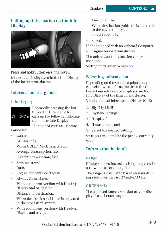
Calling up information on the InfoDisplay
Press and hold button on signal lever.
Information is displayed in the Info Displayof the instrument cluster.
Information at a glance
Info Display
Repeatedly pressing the but-ton on the turn signal levercalls up the following informa-tion in the Info Display:
If equipped with an OnboardComputer:
– Range.
– GREEN Info.
When GREEN Mode is activated.
– Average consumption, fuel.
– Current consumption, fuel.
– Average speed.
– Date.
– Engine temperature display.
– Always Open Timer.
– With equipment version with Head-upDisplay and navigation:
Distance to destination.
When destination guidance is activatedin the navigation system.
– With equipment version with Head-upDisplay and navigation:
Time of arrival.
When destination guidance is activatedin the navigation system.
– Speed Limit Info.
– Speed.
If not equipped with an Onboard Computer:
– Engine temperature display.
The unit of some information can bechanged.
Setting units, refer to page 55.
Selecting informationDepending on the vehicle equipment, youcan select what information from the On-board Computer can be displayed on theInfo Display of the instrument cluster.
Via the Central Information Display (CID):
1. "My MINI"
2. "System settings"
3. "Displays"
4. "Instrument panel"
5. Select the desired setting.
Settings are stored for the profile currentlyused.
Information in detail
RangeDisplays the estimated cruising range avail-able with the remaining fuel.
The range is calculated based on your driv-ing style over the last 20 miles/30 km.
GREEN infoThe achieved range extension may be dis-played as a bonus range.
Seite 143
Displays CONTROLS
143Online Edition for Part no. 01402723778 - VI/18
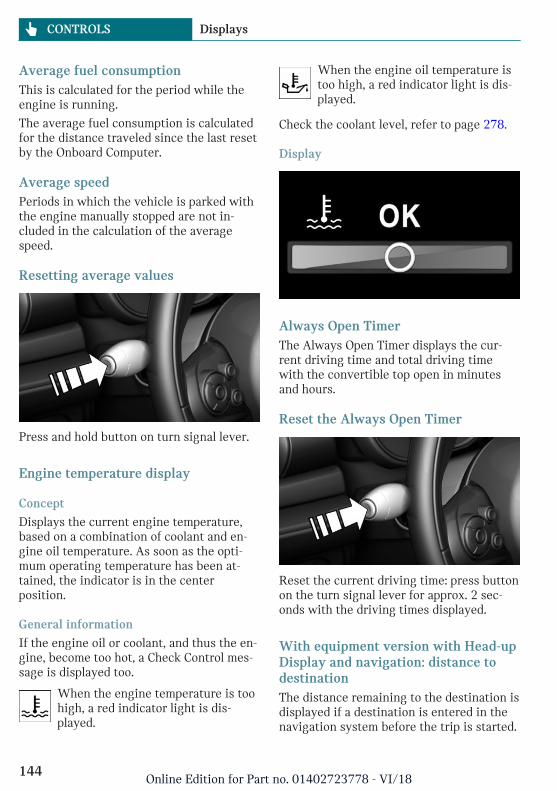
Average fuel consumptionThis is calculated for the period while theengine is running.
The average fuel consumption is calculatedfor the distance traveled since the last resetby the Onboard Computer.
Average speedPeriods in which the vehicle is parked withthe engine manually stopped are not in-cluded in the calculation of the averagespeed.
Resetting average values
Press and hold button on turn signal lever.
Engine temperature display
Concept
Displays the current engine temperature,based on a combination of coolant and en-gine oil temperature. As soon as the opti-mum operating temperature has been at-tained, the indicator is in the centerposition.
General information
If the engine oil or coolant, and thus the en-gine, become too hot, a Check Control mes-sage is displayed too.
When the engine temperature is toohigh, a red indicator light is dis-played.
When the engine oil temperature istoo high, a red indicator light is dis-played.
Check the coolant level, refer to page 278.
Display
Always Open TimerThe Always Open Timer displays the cur-rent driving time and total driving timewith the convertible top open in minutesand hours.
Reset the Always Open Timer
Reset the current driving time: press buttonon the turn signal lever for approx. 2 sec-onds with the driving times displayed.
With equipment version with Head-upDisplay and navigation: distance todestinationThe distance remaining to the destination isdisplayed if a destination is entered in thenavigation system before the trip is started.
Seite 144
CONTROLS Displays
144Online Edition for Part no. 01402723778 - VI/18
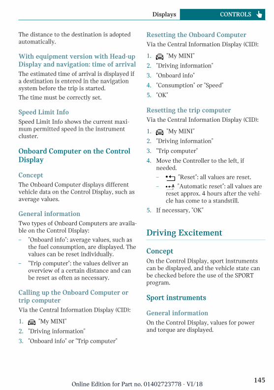
The distance to the destination is adoptedautomatically.
With equipment version with Head-upDisplay and navigation: time of arrivalThe estimated time of arrival is displayed ifa destination is entered in the navigationsystem before the trip is started.
The time must be correctly set.
Speed Limit InfoSpeed Limit Info shows the current maxi-mum permitted speed in the instrumentcluster.
Onboard Computer on the ControlDisplay
ConceptThe Onboard Computer displays differentvehicle data on the Control Display, such asaverage values.
General informationTwo types of Onboard Computers are availa-ble on the Control Display:
– "Onboard info": average values, such asthe fuel consumption, are displayed. Thevalues can be reset individually.
– "Trip computer": the values deliver anoverview of a certain distance and canbe reset as often as necessary.
Calling up the Onboard Computer ortrip computerVia the Central Information Display (CID):
1. "My MINI"
2. "Driving information"
3. "Onboard info" or "Trip computer"
Resetting the Onboard ComputerVia the Central Information Display (CID):
1. "My MINI"
2. "Driving information"
3. "Onboard info"
4. "Consumption" or "Speed"
5. "OK"
Resetting the trip computerVia the Central Information Display (CID):
1. "My MINI"
2. "Driving information"
3. "Trip computer"
4. Move the Controller to the left, ifneeded.
– "Reset": all values are reset.
– "Automatic reset": all values arereset approx. 4 hours after the vehi-cle has come to a standstill.
5. If necessary, "OK"
Driving Excitement
ConceptOn the Control Display, sport instrumentscan be displayed, and the vehicle state canbe checked before the use of the SPORTprogram.
Sport instruments
General informationOn the Control Display, values for powerand torque are displayed.
Seite 145
Displays CONTROLS
145Online Edition for Part no. 01402723778 - VI/18
Displaying sport instrumentsVia the Central Information Display (CID):
1. "My MINI"
2. "Technology in action"
3. "Sport displays"
4. "Sports instruments"
Via MINI Driving Modes switch:
1. Activate SPORT.
2. "Sport displays"
3. "Sports instruments"
Vehicle stateThe following vehicle and surrounding areadata is automatically checked and evaluatedin succession:
– Range.
– Engine temperature.
– External temperature.
– SPORT program state.
Finally, a total evaluation of the vehiclestate is displayed.
Checking vehicle stateVia the Central Information Display (CID):
1. "My MINI"
2. "Technology in action"
3. "Sport displays"
4. "Vehicle and surroundings"
Via the MINI Driving Modes switch:
1. Activate SPORT.
2. "Sport displays"
3. "Vehicle and surroundings"
Speed warning
ConceptA speed limit can be set that when reachedwill cause a warning to be issued.
General informationThe warning is repeated if the vehicle speedexceeds the set speed limit again, after ithas dropped below it by 3 mph/5 km/h.
Displaying, setting or changing thespeed warningVia the Central Information Display (CID):
1. "My MINI"
2. "Vehicle settings"
3. "Speed warning"
4. "Warning at:"
5. Turn the Controller until the desiredspeed is displayed.
6. Press the Controller.
Activating/deactivating the speedwarningVia the Central Information Display (CID):
1. "My MINI"
2. "Vehicle settings"
3. "Speed warning"
4. "Speed warning"
Setting your current speed as thespeed warningVia the Central Information Display (CID):
1. "My MINI"
2. "Vehicle settings"
3. "Speed warning"
4. "Select current speed"
Seite 146
CONTROLS Displays
146Online Edition for Part no. 01402723778 - VI/18
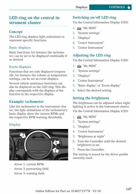
LED ring on the central in-strument cluster
ConceptThe LED ring displays light animations torepresent specific functions.
Basic displaysBasic functions, for instance the tachome-ter, can be set to be displayed continually ifso desired.
Event displaysFunctions that are only displayed tempora-rily, for instance the volume or temperaturesettings, can be set as event displays.
Several vehicle assistance functions canalso be displayed on the LED ring. This dis-play corresponds with the displays of thefunction in the respective display.
Example: tachometerLike the tachometer in the instrument clus-ter, the light animations of the tachometer'sbasic display show the current RPMs andthe respective RPM warning thresholds.
Display
– Arrow 1: current RPM.
– Arrow 2: prewarning field.
– Arrow 3: warning field.
Switching on/off LED ringVia the Central Information Display (CID):
1. "My MINI"
2. "System settings"
3. "Displays"
4. "Center Instrument"
5. "Center Instrument"
Adjusting the LED ringVia the Central Information Display (CID):
1. "My MINI"
2. "System settings"
3. "Displays"
4. "Center Instrument"
5. "Basic display" or "Event display"
6. Select the desired setting.
Setting the brightnessThe brightness can be adjusted when nightlighting is active in the instrument cluster.
Via the Central Information Display (CID):
1. "My MINI"
2. "System settings"
3. "Displays"
4. "Center Instrument"
5. "Brightness at night"
6. Turn the Controller until the desiredbrightness is set.
7. Press the Controller.
The setting is stored for the driver profilecurrently used.
Seite 147
Displays CONTROLS
147Online Edition for Part no. 01402723778 - VI/18
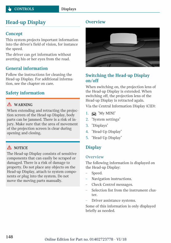
Head-up Display
ConceptThis system projects important informationinto the driver's field of vision, for instancethe speed.
The driver can get information withoutaverting his or her eyes from the road.
General informationFollow the instructions for cleaning theHead-up Display. For additional informa-tion, see the chapter on care.
Safety information
WARNING
When extending and retracting the projec-tion screen of the Head-up Display, bodyparts can be jammed. There is a risk of in-jury. Make sure that the area of movementof the projection screen is clear duringopening and closing.
NOTICE
The Head-up Display consists of sensitivecomponents that can easily be scraped ordamaged. There is a risk of damage toproperty. Do not place any objects on theHead-up Display, attach to system compo-nents or plug into the system. Do notmove the moving parts manually.
Overview
Switching the Head-up Displayon/offWhen switching on, the projection lens ofthe Head-up Display is extended. Whenswitching off, the projection lens of theHead-up Display is retracted again.
Via the Central Information Display (CID):
1. "My MINI"
2. "System settings"
3. "Displays"
4. "Head-Up Display"
5. "Head-Up Display"
Display
OverviewThe following information is displayed onthe Head-up Display:
– Speed.
– Navigation instructions.
– Check Control messages.
– Selection list from the instrument clus-ter.
– Driver assistance systems.
Some of this information is only displayedbriefly as needed.
Seite 148
CONTROLS Displays
148Online Edition for Part no. 01402723778 - VI/18
Selecting displays in the Head-upDisplayVia the Central Information Display (CID):
1. "My MINI"
2. "System settings"
3. "Displays"
4. "Head-Up Display"
5. "Displayed information"
6. Select the desired displays in the Head-up Display.
Settings are stored for the driver profilecurrently used.
Setting the brightnessThe brightness is automatically adjusted tothe ambient brightness.
The basic setting can be adjusted manually.
Via the Central Information Display (CID):
1. "My MINI"
2. "System settings"
3. "Displays"
4. "Head-Up Display"
5. "Brightness"
6. Turn the Controller until the desiredbrightness is set.
7. Press the Controller.
When the low beams are switched on, thebrightness of the Head-up Display can beadditionally influenced using the instru-ment lighting, refer to page 156.
The setting is stored for the driver profilecurrently used.
Adjusting the heightVia the Central Information Display (CID):
1. "My MINI"
2. "System settings"
3. "Displays"
4. "Head-Up Display"
5. "Height"
6. Turn the Controller until the desiredheight is reached.
7. Press the Controller.
The setting is stored for the driver profilecurrently used.
Setting the rotationThe screen of the Head-up Display can berotated around its own axis.
Via the Central Information Display (CID):
1. "My MINI"
2. "System settings"
3. "Displays"
4. "Head-Up Display"
5. "Rotation"
6. Turn the Controller until the desired set-ting is selected.
7. Press the Controller.
The setting is stored for the driver profilecurrently used.
Display visibilityThe visibility of the displays in the Head-upDisplay is influenced by the following fac-tors:
– Certain sitting positions.
– Objects on the cover of the Head-up Dis-play.
– Sunglasses with certain polarization fil-ters.
– Wet roads.
– Unfavorable light conditions.
Seite 149
Displays CONTROLS
149Online Edition for Part no. 01402723778 - VI/18
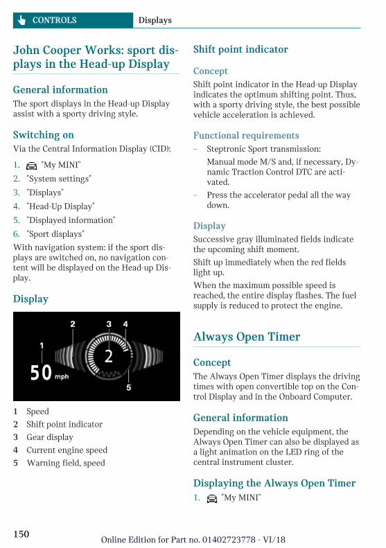
John Cooper Works: sport dis-plays in the Head-up Display
General informationThe sport displays in the Head-up Displayassist with a sporty driving style.
Switching onVia the Central Information Display (CID):
1. "My MINI"
2. "System settings"
3. "Displays"
4. "Head-Up Display"
5. "Displayed information"
6. "Sport displays"
With navigation system: if the sport dis-plays are switched on, no navigation con-tent will be displayed on the Head-up Dis-play.
Display
1 Speed
2 Shift point indicator
3 Gear display
4 Current engine speed
5 Warning field, speed
Shift point indicator
ConceptShift point indicator in the Head-up Displayindicates the optimum shifting point. Thus,with a sporty driving style, the best possiblevehicle acceleration is achieved.
Functional requirements– Steptronic Sport transmission:
Manual mode M/S and, if necessary, Dy-namic Traction Control DTC are acti-vated.
– Press the accelerator pedal all the waydown.
DisplaySuccessive gray illuminated fields indicatethe upcoming shift moment.
Shift up immediately when the red fieldslight up.
When the maximum possible speed isreached, the entire display flashes. The fuelsupply is reduced to protect the engine.
Always Open Timer
ConceptThe Always Open Timer displays the drivingtimes with open convertible top on the Con-trol Display and in the Onboard Computer.
General informationDepending on the vehicle equipment, theAlways Open Timer can also be displayed asa light animation on the LED ring of thecentral instrument cluster.
Displaying the Always Open Timer1. "My MINI"
Seite 150
CONTROLS Displays
150Online Edition for Part no. 01402723778 - VI/18
2. "Openometer"
DisplayThe following information is displayed onthe Control Display:
– Current driving time with theconvertible top open in minutes andhours.
– Total driving time with the convertibletop open in minutes and hours.
– Current external temperature while driv-ing with the convertible top open.
Maximum 99 hours and 59 minutes are dis-played for the current driving time, andmaximum 999 hours and 59 minutes for thetotal driving time.
Reset the current driving time1. "My MINI"
2. "Openometer"
3. "Reset trip"
To reset the total driving time, contact yourservice center.
Vehicle status
General informationThe status can be displayed and actions per-formed for several systems.
Opening the vehicle statusVia the Central Information Display (CID):
1. "My MINI"
2. "Vehicle status"
Information at a glance– "Flat Tire Monitor": Status of the Flat
Tire Monitor, refer to page 168.
– "Tire Pressure Monitor": Status of theTire Pressure Monitor, refer topage 163.
– "Engine oil level": Electronic en-gine oil level check, refer to page 274.
– "Check Control": Check Control mes-sages are stored in the background andcan be displayed on the Control Display.Displaying stored Check Control mes-sages, refer to page 136.
– "Service required": Displaying serv-ice requirements, refer to page 139.
– "Teleservice Call": service request.
Seite 151
Displays CONTROLS
151Online Edition for Part no. 01402723778 - VI/18
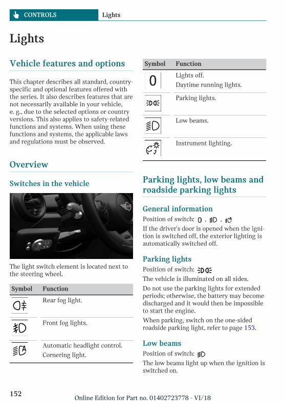
Lights
Vehicle features and options
This chapter describes all standard, country-specific and optional features offered withthe series. It also describes features that arenot necessarily available in your vehicle,e. g., due to the selected options or countryversions. This also applies to safety-relatedfunctions and systems. When using thesefunctions and systems, the applicable lawsand regulations must be observed.
Overview
Switches in the vehicle
The light switch element is located next tothe steering wheel.
Symbol Function
Rear fog light.
Front fog lights.
Automatic headlight control.
Cornering light.
Symbol Function
Lights off.
Daytime running lights.
Parking lights.
Low beams.
Instrument lighting.
Parking lights, low beams androadside parking lights
General informationPosition of switch: , ,
If the driver's door is opened when the igni-tion is switched off, the exterior lighting isautomatically switched off.
Parking lightsPosition of switch:
The vehicle is illuminated on all sides.
Do not use the parking lights for extendedperiods; otherwise, the battery may becomedischarged and it would then be impossibleto start the engine.
When parking, switch on the one-sidedroadside parking light, refer to page 153.
Low beamsPosition of switch:
The low beams light up when the ignition isswitched on.
Seite 152
CONTROLS Lights
152Online Edition for Part no. 01402723778 - VI/18
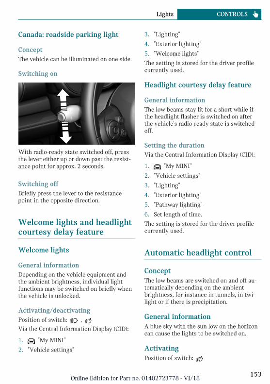
Canada: roadside parking light
ConceptThe vehicle can be illuminated on one side.
Switching on
With radio-ready state switched off, pressthe lever either up or down past the resist-ance point for approx. 2 seconds.
Switching offBriefly press the lever to the resistancepoint in the opposite direction.
Welcome lights and headlightcourtesy delay feature
Welcome lights
General informationDepending on the vehicle equipment andthe ambient brightness, individual lightfunctions may be switched on briefly whenthe vehicle is unlocked.
Activating/deactivatingPosition of switch: ,
Via the Central Information Display (CID):
1. "My MINI"
2. "Vehicle settings"
3. "Lighting"
4. "Exterior lighting"
5. "Welcome lights"
The setting is stored for the driver profilecurrently used.
Headlight courtesy delay feature
General informationThe low beams stay lit for a short while ifthe headlight flasher is switched on afterthe vehicle's radio-ready state is switchedoff.
Setting the durationVia the Central Information Display (CID):
1. "My MINI"
2. "Vehicle settings"
3. "Lighting"
4. "Exterior lighting"
5. "Pathway lighting"
6. Set length of time.
The setting is stored for the driver profilecurrently used.
Automatic headlight control
ConceptThe low beams are switched on and off au-tomatically depending on the ambientbrightness, for instance in tunnels, in twi-light or if there is precipitation.
General informationA blue sky with the sun low on the horizoncan cause the lights to be switched on.
ActivatingPosition of switch:
Seite 153
Lights CONTROLS
153Online Edition for Part no. 01402723778 - VI/18
The indicator light in the instrument clusteris illuminated when the low beams areswitched on.
System limitsThe automatic headlight control cannotserve as a substitute for your personal judg-ment of lighting conditions.
For example, the sensors are unable to de-tect fog or hazy weather. In these situa-tions, switch the light on manually.
Daytime running lights
General informationPosition of switch: , ,
The daytime running lights light up whenthe ignition is switched on. After the igni-tion is switched off, the parking lights lightup in position .
Activating/deactivatingIn some countries, daytime running lightsare mandatory, so it may not be possible todeactivate the daytime running lights.
Via the Central Information Display (CID):
1. "My MINI"
2. "Vehicle settings"
3. "Lighting"
4. "Exterior lighting"
5. Select the desired setting.
Settings are stored for the remote controlcurrently used.
Cornering light
General informationPosition of switch:
In tight curves, for instance on mountain-ous roads or when turning, an additional,cornering light is switched on that lights upthe inside of the curve when the vehicle ismoving below a certain speed.
The cornering light is automaticallyswitched on depending on the steering an-gle or the use of turn signals.
Adaptive headlight range con-trol
The adaptive headlight range control com-pensates for acceleration and braking oper-ations in order not to blind the oncomingtraffic and to achieve optimum illuminationof the roadway.
High-beam Assistant
ConceptThe high-beam Assistant detects other traf-fic participants early on and automaticallyswitches the high beams on or off depend-ing on the traffic situation.
General informationThe high-beam Assistant ensures that thehigh beams are switched on, whenever thetraffic situation allows. In the low speedrange, the high beams are not switched onby the system.
The system responds to light from oncom-ing traffic and traffic driving ahead of you,and to ambient lighting, for instance intowns and cities.
The high beams can be switched on and offmanually at any time.
Seite 154
CONTROLS Lights
154Online Edition for Part no. 01402723778 - VI/18
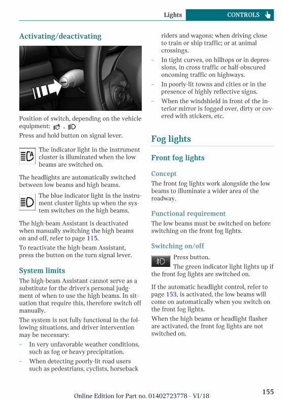
Activating/deactivating
Position of switch, depending on the vehicleequipment: ,
Press and hold button on signal lever.
The indicator light in the instrumentcluster is illuminated when the lowbeams are switched on.
The headlights are automatically switchedbetween low beams and high beams.
The blue indicator light in the instru-ment cluster lights up when the sys-tem switches on the high beams.
The high-beam Assistant is deactivatedwhen manually switching the high beamson and off, refer to page 115.
To reactivate the high-beam Assistant,press the button on the turn signal lever.
System limitsThe high-beam Assistant cannot serve as asubstitute for the driver's personal judg-ment of when to use the high beams. In sit-uation that require this, therefore switch offmanually.
The system is not fully functional in the fol-lowing situations, and driver interventionmay be necessary:
– In very unfavorable weather conditions,such as fog or heavy precipitation.
– When detecting poorly-lit road userssuch as pedestrians, cyclists, horseback
riders and wagons; when driving closeto train or ship traffic; or at animalcrossings.
– In tight curves, on hilltops or in depres-sions, in cross traffic or half-obscuredoncoming traffic on highways.
– In poorly-lit towns and cities or in thepresence of highly reflective signs.
– When the windshield in front of the in-terior mirror is fogged over, dirty or cov-ered with stickers, etc.
Fog lights
Front fog lights
ConceptThe front fog lights work alongside the lowbeams to illuminate a wider area of theroadway.
Functional requirementThe low beams must be switched on beforeswitching on the front fog lights.
Switching on/off
Press button.
The green indicator light lights up ifthe front fog lights are switched on.
If the automatic headlight control, refer topage 153, is activated, the low beams willcome on automatically when you switch onthe front fog lights.
When the high beams or headlight flasherare activated, the front fog lights are notswitched on.
Seite 155
Lights CONTROLS
155Online Edition for Part no. 01402723778 - VI/18
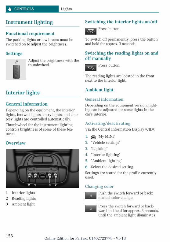
Instrument lighting
Functional requirementThe parking lights or low beams must beswitched on to adjust the brightness.
SettingsAdjust the brightness with thethumbwheel.
Interior lights
General informationDepending on the equipment, the interiorlights, footwell lights, entry lights, and cour-tesy lights are controlled automatically.
Thumbwheel for the instrument lightingcontrols brightness of some of these fea-tures.
Overview
1 Interior lights
2 Reading lights
3 Ambient light
Switching the interior lights on/offPress button.
To switch off permanently: press the buttonand hold for approx. 3 seconds.
Switching the reading lights on andoff manually
Press button.
The reading lights are located in the frontnext to the interior light.
Ambient light
General informationDepending on the equipment version, light-ing can be adjusted for some lights in thecar's interior.
Activating/deactivatingVia the Central Information Display (CID):
1. "My MINI"
2. "Vehicle settings"
3. "Lighting"
4. "Interior lighting"
5. "Ambient lighting"
6. Select the desired setting.
Settings are stored for the profile currentlyused.
Changing color
Push the switch forward or back:manual color change.
Press the switch forward or back-ward and hold for approx. 3 seconds,until the ambient light illuminates
Seite 156
CONTROLS Lights
156Online Edition for Part no. 01402723778 - VI/18
several times: automatic color change. Pushthe switch again to end color changes.
Setting the brightnessDepending on the equipment, the bright-ness of the ambient light can be adjustedvia the thumbwheel for the instrumentlighting or on the Control Display.
Via the Central Information Display (CID):
1. "My MINI"
2. "Vehicle settings"
3. "Lighting"
4. "Interior lighting"
5. "Brightness"
6. Adjust the brightness.
Seite 157
Lights CONTROLS
157Online Edition for Part no. 01402723778 - VI/18
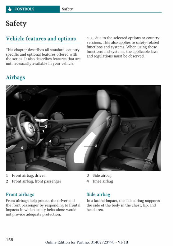
Safety
Vehicle features and options
This chapter describes all standard, country-specific and optional features offered withthe series. It also describes features that arenot necessarily available in your vehicle,
e. g., due to the selected options or countryversions. This also applies to safety-relatedfunctions and systems. When using thesefunctions and systems, the applicable lawsand regulations must be observed.
Airbags
1 Front airbag, driver
2 Front airbag, front passenger
3 Side airbag
4 Knee airbag
Front airbagsFront airbags help protect the driver andthe front passenger by responding to frontalimpacts in which safety belts alone wouldnot provide adequate protection.
Side airbagIn a lateral impact, the side airbag supportsthe side of the body in the chest, lap, andhead area.
Seite 158
CONTROLS Safety
158Online Edition for Part no. 01402723778 - VI/18
Knee airbagThe knee airbag supports the legs in a fron-tal impact.
Protective actionAirbags are not triggered in every impactsituation, for instance in less severe acci-dents or rear-end collisions.
Information on optimum effect of theairbags
WARNING
If the seat position is incorrect or the de-ployment area of the airbags is impaired,the airbag system cannot provide protec-tion as intended and may cause additionalinjuries due to triggering. There is a riskof injuries or danger to life. Follow the in-formation on achieving the optimum pro-tective effect of the airbag system.
– Keep a distance from the airbags.
– Always grasp the steering wheel on thesteering wheel rim. Hold your hands atthe 3 o'clock and 9 o'clock positions, tokeep the risk of injury to your hands orarms as low as possible when the airbagis triggered.
– Make sure that the front passenger issitting correctly, i.e., keeps his or herfeet and legs in the floor area and doesnot support them on the dashboard.
– Make sure that occupants keep theirheads away from the side airbag.
– There should be no additional persons,animals or objects between an airbagand a person.
– Dashboard and windshield on the frontpassenger side must stay clear - do notattach adhesive labels or coverings anddo not attach brackets or cables, for in-
stance for GPS devices or mobilephones.
– Do not apply adhesive materials to theairbag cover panels, do not cover themor modify them in any way.
– Do not use the cover of the front airbagon the front passenger side as a storagearea.
– Do not place slip covers, seat cushionsor other objects on the front passengerseat that are not specifically suited forseats with integrated side airbags.
– Do not place seat cushions or other ob-jects on the front seats that are not spe-cifically suited for seats with integratedside airbags.
– Do not hang pieces of clothing, such asjackets, over the backrests.
– Never modify either the individual com-ponents or the wiring in the airbag sys-tem. This also applies to steering wheelcovers, the dashboard, and the seats.
– Do not remove the airbag system.
Even when you follow all instructions veryclosely, injury from contact with the airbagscannot be fully ruled out in certain situa-tions.
The ignition and inflation noise may lead toshort-term and, in most cases, temporaryhearing impairment in sensitive occupants.
Vehicle modifications for a person with dis-abilities may affect the air bag system; con-tact MINI Customer Relations for further in-formation.
Warnings and information on the airbagsare also found on the sun visors.
Seite 159
Safety CONTROLS
159Online Edition for Part no. 01402723778 - VI/18
Functional readiness of the airbagsystem
Safety information
WARNING
Individual components can be hot aftertriggering of the airbag system. There is arisk of injury. Do not touch individualcomponents.
WARNING
Improperly executed work can lead to fail-ure, malfunction or unintentional trigger-ing of the airbag system. In the case of amalfunction, the airbag system might nottrigger as intended despite the accidentseverity. There is a risk of injuries or dan-ger to life. Have the airbag systemchecked, repaired, dismantled and scrap-ped by a dealer’s service center or anotherqualified service center or repair shop.
Correct function
When the ignition is switched on,the warning light in the instrumentcluster lights up briefly and thereby
indicates the operational readiness of theentire airbag system and the belt tensioner.
Airbag system malfunctioning– Warning light does not come on when
the ignition is switched on.
– The warning light lights up continu-ously.
Automatic deactivation of thefront-seat passenger airbags
ConceptThe system reads if the front passenger seatis occupied by measuring the human body'sresistance.
Front, knee, and side airbag on the frontpassenger's side are activated or deacti-vated.
General informationBefore transporting a child on the front pas-senger seat, refer to the safety informationand instructions for children on the frontpassenger seat, see Children.
Safety information
WARNING
To ensure the front-seat passenger airbagfunction, the system must be able to de-tect whether a person is sitting in thefront passenger seat. The entire seat cush-ion area must be used for this purpose.There is a risk of injuries or danger to life.Make sure that the front passenger keepshis or her feet in the floor area.
Malfunction of the automaticdeactivation systemWhen transporting older children andadults, the front-seat passenger airbags maybe deactivated in certain sitting positions.In this case, the indicator light for the front-seat passenger airbags lights up.
In this case, change the sitting position sothat the front-seat passenger airbags are ac-tivated and the indicator light goes out.
If it is not possible to activate the airbags,have the person sit in the rear.
Seite 160
CONTROLS Safety
160Online Edition for Part no. 01402723778 - VI/18
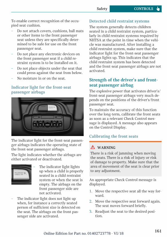
To enable correct recognition of the occu-pied seat cushion.
– Do not attach covers, cushions, ball matsor other items to the front passengerseat unless they are specifically deter-mined to be safe for use on the frontpassenger seat.
– Do not place any electronic devices onthe front passenger seat if a child re-straint system is to be installed on it.
– Do not place objects under the seat thatcould press against the seat from below.
– No moisture in or on the seat.
Indicator light for the front-seatpassenger airbags
The indicator light for the front-seat passen-ger airbags indicates the operating state ofthe front-seat passenger airbags.
The light indicates whether the airbags areeither activated or deactivated.
– The indicator light lightsup when a child is properlyseated in a child restraintsystem or when the seat isempty. The airbags on thefront passenger side arenot activated.
– The indicator light does not light upwhen, for instance a correctly seatedperson of sufficient size is detected onthe seat. The airbags on the front pas-senger side are activated.
Detected child restraint systemsThe system generally detects childrenseated in a child restraint system, particu-larly in child restraint systems required byNHTSA at the point in time when the vehi-cle was manufactured. After installing achild restraint system, make sure that theindicator light for the front-seat passengerairbags lights up. This indicates that thechild restraint system has been detectedand the front-seat passenger airbags are notactivated.
Strength of the driver's and front-seat passenger airbagThe explosive power that activates driver's/front-seat passenger airbags very much de-pends on the positions of the driver's/frontpassenger seat.
To maintain the accuracy of this functionover the long-term, calibrate the front seatsas soon as a relevant Check Control mes-sage is displayed. A message also appearson the Control Display.
Calibrating the front seats
WARNING
There is a risk of jamming when movingthe seats. There is a risk of injury or riskof damage to property. Make sure that thearea of movement of the seat is clear priorto any adjustment.
An appropriate Check Control message isdisplayed.
1. Move the respective seat all the way for-ward.
2. Move the respective seat forward again.The seat moves forward briefly.
3. Readjust the seat to the desired posi-tion.
Seite 161
Safety CONTROLS
161Online Edition for Part no. 01402723778 - VI/18
The calibration procedure is completedwhen the Check Control message disap-pears.
If the message continues to be displayed,repeat the calibration.
If the message does not disappear after a re-peat calibration, have the system checkedas soon as possible.
Rollover protection system
ConceptThe rollover protection system is automati-cally activated in the event of a sufficientlyserious accident or if the longitudinal axisis tilted excessively. The safety frames lo-cated behind the rear head restraints extendwithin fractions of a second.
Supplementing the reinforced windshieldframe, the rollover protection system fur-ther increases passenger safety.
General informationDo not place any objects on the covers ofthe rollover protection system.
Safety information
WARNING
There can be damage or injuries when therollover protection system is triggered.There is a risk of injury or risk of damageto property. Make sure that the area ofmovement of the rollover protection sys-tem is clear.
WARNING
Improperly executed work can lead to fail-ure, malfunction or unintentional trigger-ing of the system. In the case of a malfunc-tion, the system might not trigger asintended even if there is an accident se-vere enough to warrant it. There is a riskof injuries or danger to life. Have the sys-tem checked, repaired, dismantled andscrapped by a dealer’s service center oranother qualified service center or repairshop.
WARNING
After triggering or damage, system func-tionality is limited or not available any-more. There is a risk of injuries or dangerto life.
Have the system checked and replaced bya dealer’s service center or another quali-fied service center or repair shop in theevent of triggering of or damage to thesystem.
WARNING
With an extended rollover protection sys-tem, the area of movement of theconvertible top is limited. There is a riskof injury or risk of damage to property.When the rollover protection system is ex-tended, do not move the convertible top.
Seite 162
CONTROLS Safety
162Online Edition for Part no. 01402723778 - VI/18
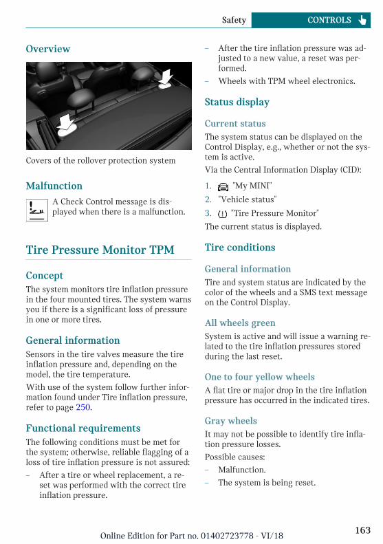
Overview
Covers of the rollover protection system
MalfunctionA Check Control message is dis-played when there is a malfunction.
Tire Pressure Monitor TPM
ConceptThe system monitors tire inflation pressurein the four mounted tires. The system warnsyou if there is a significant loss of pressurein one or more tires.
General informationSensors in the tire valves measure the tireinflation pressure and, depending on themodel, the tire temperature.
With use of the system follow further infor-mation found under Tire inflation pressure,refer to page 250.
Functional requirementsThe following conditions must be met forthe system; otherwise, reliable flagging of aloss of tire inflation pressure is not assured:
– After a tire or wheel replacement, a re-set was performed with the correct tireinflation pressure.
– After the tire inflation pressure was ad-justed to a new value, a reset was per-formed.
– Wheels with TPM wheel electronics.
Status display
Current statusThe system status can be displayed on theControl Display, e.g., whether or not the sys-tem is active.
Via the Central Information Display (CID):
1. "My MINI"
2. "Vehicle status"
3. "Tire Pressure Monitor"
The current status is displayed.
Tire conditions
General informationTire and system status are indicated by thecolor of the wheels and a SMS text messageon the Control Display.
All wheels greenSystem is active and will issue a warning re-lated to the tire inflation pressures storedduring the last reset.
One to four yellow wheelsA flat tire or major drop in the tire inflationpressure has occurred in the indicated tires.
Gray wheelsIt may not be possible to identify tire infla-tion pressure losses.
Possible causes:
– Malfunction.
– The system is being reset.
Seite 163
Safety CONTROLS
163Online Edition for Part no. 01402723778 - VI/18
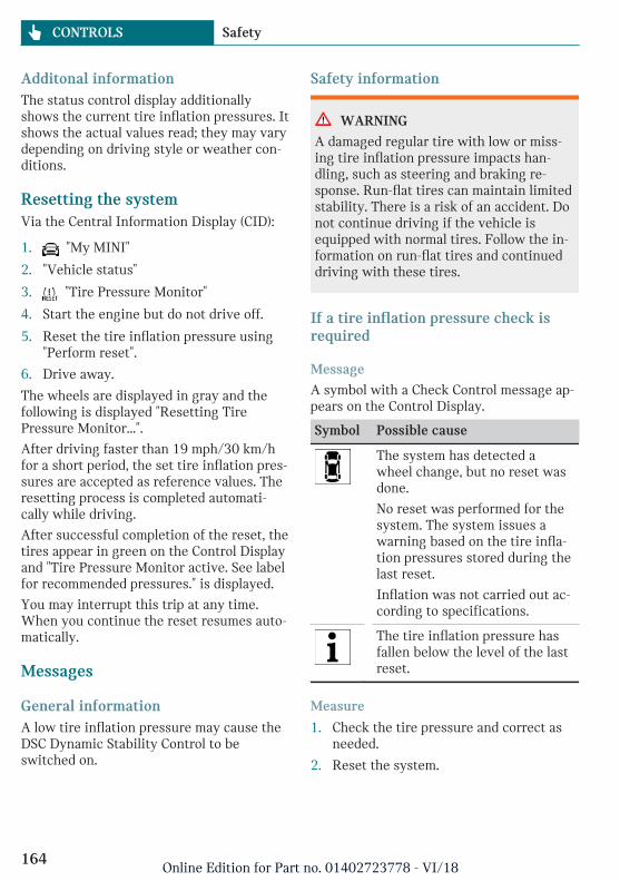
Additonal informationThe status control display additionallyshows the current tire inflation pressures. Itshows the actual values read; they may varydepending on driving style or weather con-ditions.
Resetting the systemVia the Central Information Display (CID):
1. "My MINI"
2. "Vehicle status"
3. "Tire Pressure Monitor"
4. Start the engine but do not drive off.
5. Reset the tire inflation pressure using"Perform reset".
6. Drive away.
The wheels are displayed in gray and thefollowing is displayed "Resetting TirePressure Monitor…".
After driving faster than 19 mph/30 km/hfor a short period, the set tire inflation pres-sures are accepted as reference values. Theresetting process is completed automati-cally while driving.
After successful completion of the reset, thetires appear in green on the Control Displayand "Tire Pressure Monitor active. See labelfor recommended pressures." is displayed.
You may interrupt this trip at any time.When you continue the reset resumes auto-matically.
Messages
General informationA low tire inflation pressure may cause theDSC Dynamic Stability Control to beswitched on.
Safety information
WARNING
A damaged regular tire with low or miss-ing tire inflation pressure impacts han-dling, such as steering and braking re-sponse. Run-flat tires can maintain limitedstability. There is a risk of an accident. Donot continue driving if the vehicle isequipped with normal tires. Follow the in-formation on run-flat tires and continueddriving with these tires.
If a tire inflation pressure check isrequired
Message
A symbol with a Check Control message ap-pears on the Control Display.
Symbol Possible cause
The system has detected awheel change, but no reset wasdone.
No reset was performed for thesystem. The system issues awarning based on the tire infla-tion pressures stored during thelast reset.
Inflation was not carried out ac-cording to specifications.
The tire inflation pressure hasfallen below the level of the lastreset.
Measure
1. Check the tire pressure and correct asneeded.
2. Reset the system.
Seite 164
CONTROLS Safety
164Online Edition for Part no. 01402723778 - VI/18
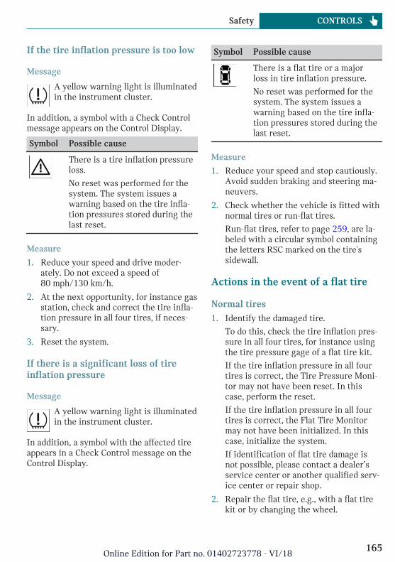
If the tire inflation pressure is too low
Message
A yellow warning light is illuminatedin the instrument cluster.
In addition, a symbol with a Check Controlmessage appears on the Control Display.
Symbol Possible cause
There is a tire inflation pressureloss.
No reset was performed for thesystem. The system issues awarning based on the tire infla-tion pressures stored during thelast reset.
Measure
1. Reduce your speed and drive moder-ately. Do not exceed a speed of80 mph/130 km/h.
2. At the next opportunity, for instance gasstation, check and correct the tire infla-tion pressure in all four tires, if neces-sary.
3. Reset the system.
If there is a significant loss of tireinflation pressure
Message
A yellow warning light is illuminatedin the instrument cluster.
In addition, a symbol with the affected tireappears in a Check Control message on theControl Display.
Symbol Possible cause
There is a flat tire or a majorloss in tire inflation pressure.
No reset was performed for thesystem. The system issues awarning based on the tire infla-tion pressures stored during thelast reset.
Measure
1. Reduce your speed and stop cautiously.Avoid sudden braking and steering ma-neuvers.
2. Check whether the vehicle is fitted withnormal tires or run-flat tires.
Run-flat tires, refer to page 259, are la-beled with a circular symbol containingthe letters RSC marked on the tire'ssidewall.
Actions in the event of a flat tire
Normal tires1. Identify the damaged tire.
To do this, check the tire inflation pres-sure in all four tires, for instance usingthe tire pressure gage of a flat tire kit.
If the tire inflation pressure in all fourtires is correct, the Tire Pressure Moni-tor may not have been reset. In thiscase, perform the reset.
If the tire inflation pressure in all fourtires is correct, the Flat Tire Monitormay not have been initialized. In thiscase, initialize the system.
If identification of flat tire damage isnot possible, please contact a dealer’sservice center or another qualified serv-ice center or repair shop.
2. Repair the flat tire, e.g., with a flat tirekit or by changing the wheel.
Seite 165
Safety CONTROLS
165Online Edition for Part no. 01402723778 - VI/18
Use of sealant, for instance from the flat tirekit, may damage the TPM wheel electronics.In this case, have the electronics checkedand replaced at the next opportunity.
Run-flat tires
Safety information
WARNING
Your vehicle handles differently with arun-flat with no or low inflation pressure;for instance, your lane stability whenbraking is reduced, braking distances arelonger and the self-steering properties willchange. There is a risk of an accident.Drive moderately and do not exceed aspeed of 50 mph/80 km/h.
Maximum speed
You may continue driving with a damagedtire at speeds up to 50 mph/80 km/h.
Continued driving with a flat tire
If continuing to drive with a damaged tire:
1. Avoid sudden braking and steering ma-neuvers.
2. Do not exceed a speed of50 mph/80 km/h.
3. Check the tire inflation pressure in allfour tires at the next opportunity.
If the tire inflation pressure in all fourtires is correct, the Tire Pressure Moni-tor may not have been reset. In thiscase, perform the reset.
Possible driving range with adepressurized tire
The distance for which it may be possible todrive safely varies depending on how thevehicle is loaded and used, e.g., speed, roadconditions, external temperature. The driv-
ing range may be less but may also be moreif an economical driving style is used.
If the vehicle is loaded with an averageweight and used under favorable conditions,the distance for which it may be safe todrive may be up to 50 miles/80 km.
Vehicle handling with damaged tires
Vehicles driven with a damaged tire willhandle differently, potentially leading toconditions such as the following:
– Greater likelihood of swerving offcourse.
– Longer braking distances.
– Changed self-steering properties.
Modify your driving style. Avoid abruptsteering maneuvers or driving over obsta-cles, for instance curbs or potholes.
Final tire failure
Vibrations or loud noises while driving canindicate the final failure of a tire.
Reduce speed and stop; otherwise, pieces ofthe tire could come loose and cause an acci-dent.
Do not continue driving. Contact a dealer’sservice center or another qualified servicecenter or repair shop.
System limits
TemperatureThe tire inflation pressure depends on thetire's temperature.
Driving or exposure to the sun will increasethe tire's temperature, thus increasing thetire inflation pressure.
The tire inflation pressure is reduced whenthe tire temperature falls again.
These circumstances may cause a warningwhen temperatures fall very sharply.
Seite 166
CONTROLS Safety
166Online Edition for Part no. 01402723778 - VI/18
Sudden tire pressure lossThe system cannot indicate sudden serioustire damage caused by external circumstan-ces.
Failure to perform a resetThe system does not function properly if areset has not been carried out, for instancea flat tire is reported though tire inflationpressures are correct.
MalfunctionThe yellow warning light flashes andis then illuminated continuously. ACheck Control message is displayed.
It may not be possible to identify tire pres-sure losses.
Examples and recommendations in the fol-lowing situations:
– A wheel without TPM wheel electronics,for instance an emergency wheel, ismounted: have it checked by a dealer’sservice center or another qualified serv-ice center or repair shop as needed.
– Malfunction: have system checked by adealer’s service center or another quali-fied service center or repair shop.
– The system was unable to complete thereset. Perform a system reset again.
– Interference caused by systems or devi-ces with the same radio frequency: afterleaving the area of the interference, thesystem automatically becomes activeagain.
Declaration according to NHTSA/FMVSS 138 Tire Pressure MonitoringSystemEach tire, including the spare (if provided)should be checked monthly when cold andinflated to the inflation pressure recom-mended by the vehicle manufacturer on thevehicle placard or tire inflation pressure la-
bel. (If your vehicle has tires of a differentsize than the size indicated on the vehicleplacard or tire inflation pressure label, youshould determine the proper tire inflationpressure for those tires.) As an added safetyfeature, your vehicle has been equippedwith a tire pressure monitoring system(TPMS) that illuminates a low tire pressuretelltale when one or more of your tires issignificantly under-inflated. Accordingly,when the low tire pressure telltale illumi-nates, you should stop and check your tiresas soon as possible, and inflate them to theproper pressure. Driving on a significantlyunder-inflated tire causes the tire to over-heat and can lead to tire failure. Under-infla-tion also reduces fuel efficiency and tiretread life, and may affect the vehicle's han-dling and stopping ability. Please note thatthe TPMS is not a substitute for proper tiremaintenance, and it is the driver's responsi-bility to maintain correct tire pressure, evenif under-inflation has not reached the levelto trigger illumination of the TPMS low tirepressure telltale. Your vehicle has also beenequipped with a TPMS malfunction indica-tor to indicate when the system is not oper-ating properly. The TPMS malfunction indi-cator is combined with the low tire pressuretelltale. When the system detects a mal-function, the telltale will flash for approxi-mately one minute and then remain contin-uously illuminated. This sequence willcontinue upon subsequent vehicle start-upsas long as the malfunction exists. When themalfunction indicator is illuminated, thesystem may not be able to detect or signallow tire pressure as intended. TPMS mal-functions may occur for a variety of rea-sons, including the installation of replace-ment or alternate tires or wheels on thevehicle that prevent the TPMS from func-tioning properly. Always check the TPMSmalfunction telltale after replacing one ormore tires or wheels on your vehicle to en-sure that the replacement or alternate tires
Seite 167
Safety CONTROLS
167Online Edition for Part no. 01402723778 - VI/18
and wheels allow the TPMS to continue tofunction properly.
FTM Flat Tire Monitor
ConceptThe system detects tire inflation pressureloss on the basis of rotation speed differen-ces between the individual wheels whiledriving.
In the event of a tire inflation pressure loss,the diameter and therefore the rotationalspeed of the corresponding wheel changes.The difference will be detected and reportedas a flat tire.
The system does not measure the actual in-flation pressure in the tires.
Functional requirementsThe following conditions must be met forthe system; otherwise, reliable flagging of aloss of tire inflation pressure is not assured:
– After a tire or wheel replacement, an ini-tialization was performed with the cor-rect tire inflation pressure.
– After the tire inflation pressure was ad-justed to a new value, an initializationwas performed.
Status displayThe current status of the flat tire monitorcan be displayed, for instance whether theRPA is active.
Via the Central Information Display (CID):
1. "My MINI"
2. "Vehicle status"
3. "Flat Tire Monitor"
The status is displayed.
Initialization requiredAn initialization must be performed in thefollowing situations:
– After the tire inflation pressure hasbeen adjusted.
– After a tire or wheel replacement.
Performing initializationWhen initializing, the set tire inflationpressures serve as reference values in orderto detect a flat tire. Initialization is startedby confirming the tire inflation pressures.
Do not initialize the system when drivingwith snow chains.
Via the Central Information Display (CID):
1. "My MINI"
2. "Vehicle status"
3. "Flat Tire Monitor"
4. Start the engine but do not drive off.
5. Start the initialization with: "Performreset".
6. Drive away.
The initialization is completed while driv-ing, which can be interrupted at any time.
The initialization automatically continueswhen driving resumes.
Messages
General informationWhen a flat tire is indicated, DSC DynamicStability Control is switched on, if needed.
Safety information
WARNING
A damaged regular tire with low or miss-ing tire inflation pressure impacts han-dling, such as steering and braking re-sponse. Run-flat tires can maintain limited
Seite 168
CONTROLS Safety
168Online Edition for Part no. 01402723778 - VI/18
stability. There is a risk of an accident. Donot continue driving if the vehicle isequipped with normal tires. Follow the in-formation on run-flat tires and continueddriving with these tires.
Indication of a flat tire
A yellow warning light is illuminatedin the instrument cluster.
In addition, a symbol with a Check Controlmessage appears on the Control Display.
Symbol Possible cause
There is a flat tire or a majorloss in tire inflation pressure.
Measure1. Reduce your speed and stop cautiously.
Avoid sudden braking and steering ma-neuvers.
2. Check whether the vehicle is fitted withnormal tires or run-flat tires.
Run-flat tires, refer to page 259, are la-beled with a circular symbol containingthe letters RSC marked on the tire'ssidewall.
Actions in the event of a flat tire
Normal tires1. Identify the damaged tire.
To do this, check the tire inflation pres-sure in all four tires, for instance usingthe tire pressure gage of a flat tire kit.
If the tire inflation pressure in all fourtires is correct, the Tire Pressure Moni-tor may not have been reset. In thiscase, perform the reset.
If the tire inflation pressure in all fourtires is correct, the Flat Tire Monitor
may not have been initialized. In thiscase, initialize the system.
If identification of flat tire damage isnot possible, please contact a dealer’sservice center or another qualified serv-ice center or repair shop.
2. Repair the flat tire, e.g., with a flat tirekit or by changing the wheel.
Use of sealant, for instance from the flat tirekit, may damage the TPM wheel electronics.In this case, have the electronics checkedand replaced at the next opportunity.
Run-flat tires
Safety information
WARNING
Your vehicle handles differently with arun-flat with no or low inflation pressure;for instance, your lane stability whenbraking is reduced, braking distances arelonger and the self-steering properties willchange. There is a risk of an accident.Drive moderately and do not exceed aspeed of 50 mph/80 km/h.
Maximum speed
You may continue driving with a damagedtire at speeds up to 50 mph/80 km/h.
Continued driving with a flat tire
If continuing to drive with a damaged tire:
1. Avoid sudden braking and steering ma-neuvers.
2. Do not exceed a speed of50 mph/80 km/h.
3. Check the tire inflation pressure in allfour tires at the next opportunity.
If the tire inflation pressure in all fourtires is correct, the Flat Tire Monitor
Seite 169
Safety CONTROLS
169Online Edition for Part no. 01402723778 - VI/18
may not have been initialized. In thiscase, initialize the system.
Possible driving range with adepressurized tire
The distance for which it may be possible todrive safely varies depending on how thevehicle is loaded and used, e.g., speed, roadconditions, external temperature. The driv-ing range may be less but may also be moreif an economical driving style is used.
If the vehicle is loaded with an averageweight and used under favorable conditions,the distance for which it may be safe todrive may be up to 50 miles/80 km.
Vehicle handling with damaged tires
Vehicles driven with a damaged tire willhandle differently, potentially leading toconditions such as the following:
– Greater likelihood of swerving offcourse.
– Longer braking distances.
– Changed self-steering properties.
Modify your driving style. Avoid abruptsteering maneuvers or driving over obsta-cles, for instance curbs or potholes.
Final tire failure
Vibrations or loud noises while driving canindicate the final failure of a tire.
Reduce speed and stop; otherwise, pieces ofthe tire could come loose and cause an acci-dent.
Do not continue driving. Contact a dealer’sservice center or another qualified servicecenter or repair shop.
System limitsThe system could be delayed or malfunctionin the following situations:
– A natural, even tire inflation pressureloss in all four tires will not be recog-
nized. Therefore, check the tire inflationpressure regularly.
– Sudden serious tire damage caused byexternal circumstances cannot be recog-nized in advance.
– When the system has not been initial-ized.
– When driving on a snowy or slipperyroad surface.
– Sporty driving style: spinning tractionwheels, high lateral acceleration (drift-ing).
– When driving with snow chains.
Intelligent Safety
ConceptIntelligent Safety enables central operationof the driver assistance system.
The intelligent safety systems can help pre-vent an imminent collision.
– Approach control warning with Citylight braking function, refer topage 171.
– Person warning with City light brakingfunction, refer to page 175.
Safety information
WARNING
The system cannot serve as a substitutefor the driver’s personal judgment in as-sessing visibility and traffic situation.There is a risk of an accident. Adjust driv-ing style to traffic conditions. Watch traf-fic closely and actively intervene whereappropriate.
Seite 170
CONTROLS Safety
170Online Edition for Part no. 01402723778 - VI/18
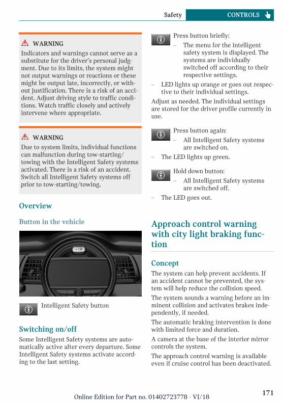
WARNING
Indicators and warnings cannot serve as asubstitute for the driver’s personal judg-ment. Due to its limits, the system mightnot output warnings or reactions or thesemight be output late, incorrectly, or with-out justification. There is a risk of an acci-dent. Adjust driving style to traffic condi-tions. Watch traffic closely and activelyintervene where appropriate.
WARNING
Due to system limits, individual functionscan malfunction during tow-starting/towing with the Intelligent Safety systemsactivated. There is a risk of an accident.Switch all Intelligent Safety systems offprior to tow-starting/towing.
Overview
Button in the vehicle
Intelligent Safety button
Switching on/offSome Intelligent Safety systems are auto-matically active after every departure. SomeIntelligent Safety systems activate accord-ing to the last setting.
Press button briefly:
– The menu for the intelligentsafety system is displayed. Thesystems are individuallyswitched off according to theirrespective settings.
– LED lights up orange or goes out respec-tive to their individual settings.
Adjust as needed. The individual settingsare stored for the driver profile currently inuse.
Press button again:
– All Intelligent Safety systemsare switched on.
– The LED lights up green.
Hold down button:
– All Intelligent Safety systemsare switched off.
– The LED goes out.
Approach control warningwith city light braking func-tion
ConceptThe system can help prevent accidents. Ifan accident cannot be prevented, the sys-tem will help reduce the collision speed.
The system sounds a warning before an im-minent collision and activates brakes inde-pendently, if needed.
The automatic braking intervention is donewith limited force and duration.
A camera at the base of the interior mirrorcontrols the system.
The approach control warning is availableeven if cruise control has been deactivated.
Seite 171
Safety CONTROLS
171Online Edition for Part no. 01402723778 - VI/18
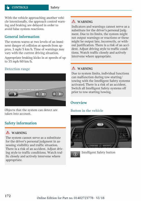
With the vehicle approaching another vehi-cle intentionally, the approach control warn-ing and braking are delayed in order toavoid false system reactions.
General informationThe system warns at two levels of an immi-nent danger of collision at speeds from ap-prox. 3 mph/5 km/h. Time of warnings mayvary with the current driving situation.
Appropriate braking kicks in at speeds of upto 35 mph/60 km/h.
Detection range
Objects that the system can detect aretaken into account.
Safety information
WARNING
The system cannot serve as a substitutefor the driver’s personal judgment in as-sessing visibility and traffic situation.There is a risk of an accident. Adjust driv-ing style to traffic conditions. Watch traf-fic closely and actively intervene whereappropriate.
WARNING
Indicators and warnings cannot serve as asubstitute for the driver’s personal judg-ment. Due to its limits, the system mightnot output warnings or reactions or thesemight be output late, incorrectly, or with-out justification. There is a risk of an acci-dent. Adjust driving style to traffic condi-tions. Watch traffic closely and activelyintervene where appropriate.
WARNING
Due to system limits, individual functionscan malfunction during tow-starting/towing with the Intelligent Safety systemsactivated. There is a risk of an accident.Switch all Intelligent Safety systems offprior to tow-starting/towing.
Overview
Button in the vehicle
Intelligent Safety button
Seite 172
CONTROLS Safety
172Online Edition for Part no. 01402723778 - VI/18
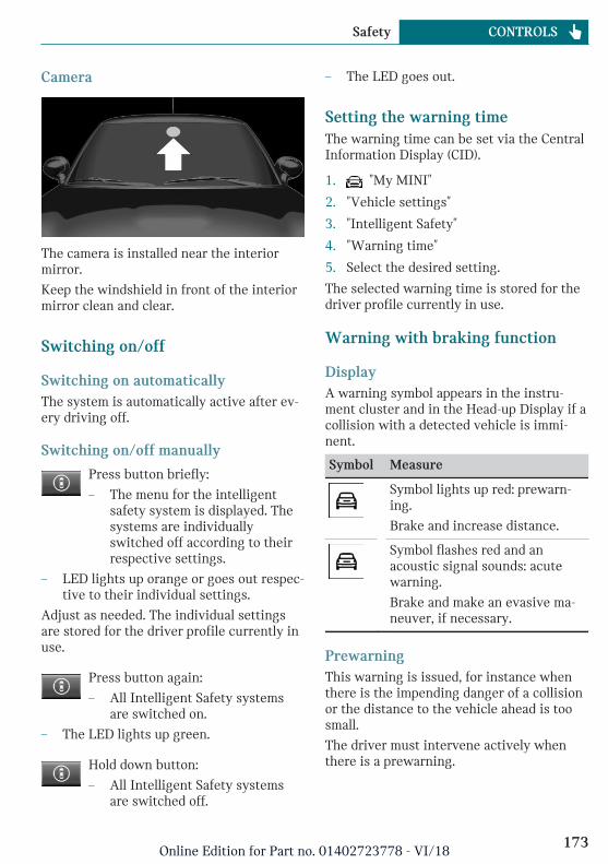
Camera
The camera is installed near the interiormirror.
Keep the windshield in front of the interiormirror clean and clear.
Switching on/off
Switching on automaticallyThe system is automatically active after ev-ery driving off.
Switching on/off manually
Press button briefly:
– The menu for the intelligentsafety system is displayed. Thesystems are individuallyswitched off according to theirrespective settings.
– LED lights up orange or goes out respec-tive to their individual settings.
Adjust as needed. The individual settingsare stored for the driver profile currently inuse.
Press button again:
– All Intelligent Safety systemsare switched on.
– The LED lights up green.
Hold down button:
– All Intelligent Safety systemsare switched off.
– The LED goes out.
Setting the warning timeThe warning time can be set via the CentralInformation Display (CID).
1. "My MINI"
2. "Vehicle settings"
3. "Intelligent Safety"
4. "Warning time"
5. Select the desired setting.
The selected warning time is stored for thedriver profile currently in use.
Warning with braking function
DisplayA warning symbol appears in the instru-ment cluster and in the Head-up Display if acollision with a detected vehicle is immi-nent.
Symbol Measure
Symbol lights up red: prewarn-ing.
Brake and increase distance.
Symbol flashes red and anacoustic signal sounds: acutewarning.
Brake and make an evasive ma-neuver, if necessary.
PrewarningThis warning is issued, for instance whenthere is the impending danger of a collisionor the distance to the vehicle ahead is toosmall.
The driver must intervene actively whenthere is a prewarning.
Seite 173
Safety CONTROLS
173Online Edition for Part no. 01402723778 - VI/18
Acute warning with braking functionAcute warning is displayed in case of theimminent danger of a collision when the ve-hicle approaches another object at a highdifferential speed.
The driver must intervene actively whenthere is an acute warning. If necessary, thedriver is assisted by a minor automaticbraking intervention in a possible risk ofcollision.
Acute warnings can also be triggered with-out previous forewarning.
Braking interventionThe warning prompts the driver to react.During a warning, the maximum brakingforce is used. Prerequisite for the brakebooster is sufficiently quick and sufficientlyhard stepping on the brake pedal. If there isa risk of collision, the system may assistwith braking.When the vehicle is travelingat a low speed, the vehicle may come to acomplete stop.
Manual transmission: during a braking in-tervention up to a complete stop, the enginemay be shut down.
The braking intervention occurs only if ve-hicle stability has not been restricted,for instance by deactivating the DSC Dy-namic Stability Control.
The driver may cancel the braking interven-tion by stepping on the accelerator pedal orby actively moving the steering wheel.
Object detection can be restricted. Followthe limitations of the detection range andfunctional restrictions.
System limits
Safety information
WARNING
The system can react not at all, too late, in-correctly, or without justification due tothe system limits. There is a risk of acci-dents or risk of damage to property. Followthe information regarding the system lim-its and actively intervene if needed.
Detection rangeThe system's detection potential is limited.
Thus, a system reaction might not come ormight come late.
E.g., the following situations may not be de-tected:
– Slow moving vehicles when you ap-proach them at high speed.
– Vehicles that suddenly swerve in frontof you, or sharply decelerating vehicles.
– Vehicles with an unusual rear appear-ance.
– Two-wheeled vehicles ahead of you.
Functional limitationsThe system may not be fully functional inthe following situations:
– In heavy fog, wet conditions, or snow-fall.
– In tight curves.
– If the field of view of the camera or thewindshield are dirty or covered.
– If the driving stability control systemsare deactivated, for instance DSC OFF.
– Up to 10 seconds after the start of theengine via the Start/Stop button.
– During calibration of the camera imme-diately after vehicle delivery.
Seite 174
CONTROLS Safety
174Online Edition for Part no. 01402723778 - VI/18
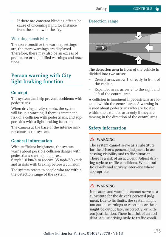
– If there are constant blinding effects be-cause of oncoming light, for instancefrom the sun low in the sky.
Warning sensitivityThe more sensitive the warning settingsare, the more warnings are displayed.Therefore, there may also be an excess ofpremature or unjustified warnings and reac-tions.
Person warning with Citylight braking function
ConceptThe system can help prevent accidents withpedestrians.
When driving at city speeds, the systemwill issue a warning if there is imminentrisk of a collision with pedestrians, and sup-port this with a light braking function.
The camera at the base of the interior mir-ror controls the system.
General informationWith sufficient brightness, the systemwarns about possible collision danger withpedestrians starting at approx.6 mph/10 km/h to approx. 35 mph/60 km/hand assists with braking before a collision.
The system reacts to people who are withinthe detection range of the system.
Detection range
The detection area in front of the vehicle isdivided into two areas:
– Central area, arrow 1, directly in front ofthe vehicle.
– Expanded area, arrow 2, to the right andleft of the central area.
A collision is imminent if pedestrians are lo-cated within the central area. A warning isissued about pedestrians who are locatedwithin the extended area only if they aremoving in the direction of the central area.
Safety information
WARNING
The system cannot serve as a substitutefor the driver’s personal judgment in as-sessing visibility and traffic situation.There is a risk of an accident. Adjust driv-ing style to traffic conditions. Watch traf-fic closely and actively intervene whereappropriate.
WARNING
Indicators and warnings cannot serve as asubstitute for the driver’s personal judg-ment. Due to its limits, the system mightnot output warnings or reactions or thesemight be output late, incorrectly, or with-out justification. There is a risk of an acci-dent. Adjust driving style to traffic condi-
Seite 175
Safety CONTROLS
175Online Edition for Part no. 01402723778 - VI/18
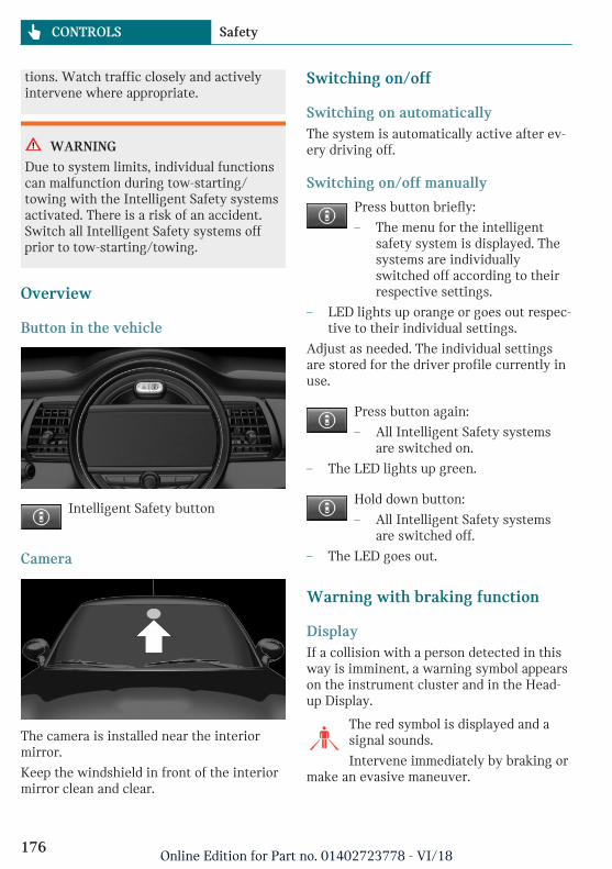
tions. Watch traffic closely and activelyintervene where appropriate.
WARNING
Due to system limits, individual functionscan malfunction during tow-starting/towing with the Intelligent Safety systemsactivated. There is a risk of an accident.Switch all Intelligent Safety systems offprior to tow-starting/towing.
Overview
Button in the vehicle
Intelligent Safety button
Camera
The camera is installed near the interiormirror.
Keep the windshield in front of the interiormirror clean and clear.
Switching on/off
Switching on automaticallyThe system is automatically active after ev-ery driving off.
Switching on/off manually
Press button briefly:
– The menu for the intelligentsafety system is displayed. Thesystems are individuallyswitched off according to theirrespective settings.
– LED lights up orange or goes out respec-tive to their individual settings.
Adjust as needed. The individual settingsare stored for the driver profile currently inuse.
Press button again:
– All Intelligent Safety systemsare switched on.
– The LED lights up green.
Hold down button:
– All Intelligent Safety systemsare switched off.
– The LED goes out.
Warning with braking function
DisplayIf a collision with a person detected in thisway is imminent, a warning symbol appearson the instrument cluster and in the Head-up Display.
The red symbol is displayed and asignal sounds.
Intervene immediately by braking ormake an evasive maneuver.
Seite 176
CONTROLS Safety
176Online Edition for Part no. 01402723778 - VI/18
Braking interventionThe warning prompts the driver to react.During a warning, the maximum brakingforce is used. Prerequisite for the brakebooster is sufficiently quick and sufficientlyhard stepping on the brake pedal. If there isa risk of collision, the system may assistwith braking.When the vehicle is travelingat a low speed, the vehicle may come to acomplete stop.
Manual transmission: during a braking in-tervention up to a complete stop, the enginemay be shut down.
The braking intervention occurs only if ve-hicle stability has not been restricted,for instance by deactivating the DSC Dy-namic Stability Control.
The driver may cancel the braking interven-tion by stepping on the accelerator pedal orby actively moving the steering wheel.
Object detection can be restricted. Followthe limitations of the detection range andfunctional restrictions.
System limits
Safety information
WARNING
The system can react not at all, too late, in-correctly, or without justification due tothe system limits. There is a risk of acci-dents or risk of damage to property. Followthe information regarding the system lim-its and actively intervene if needed.
Detection rangeThe detection potential of the camera is lim-ited.
Thus, a warning might not be issued or beissued late.
E.g., the following situations may not be de-tected:
– Partially covered pedestrians.
– Pedestrians that are not detected assuch because of the viewing angle orcontour.
– Pedestrians outside of the detectionrange.
– Pedestrians having a body size less than32 in/80 cm.
Functional limitationsThe system may not be fully functional ormay not be available in the following situa-tions:
– In heavy fog, wet conditions, or snow-fall.
– In tight curves.
– If the field of view of the camera or thewindshield are dirty or covered.
– If the driving stability control systemsare deactivated, for instance DSC OFF.
– Up to 10 seconds after the start of theengine via the Start/Stop button.
– During calibration of the camera imme-diately after vehicle delivery.
– If there are constant blinding effects be-cause of oncoming light, for instancefrom the sun low in the sky.
– When it is dark outside.
Brake force display
ConceptAdditional brake lights indicate emergencybraking to the traffic behind. This can re-duce the risk of a rear-end collision.
Seite 177
Safety CONTROLS
177Online Edition for Part no. 01402723778 - VI/18
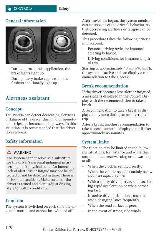
General information
– During normal brake application, thebrake lights light up.
– During heavy brake application, theflashers additionally light up.
Alertness assistant
ConceptThe system can detect decreasing alertnessor fatigue of the driver during long, monoto-nous trips, for instance on highways. In thissituation, it is recommended that the drivertakes a break.
Safety information
WARNING
The system cannot serve as a substitutefor the driver’s personal judgment in as-sessing one's physical state. An increasinglack of alertness or fatigue may not be de-tected or not be detected in time. There isa risk of an accident. Make sure that thedriver is rested and alert. Adjust drivingstyle to traffic conditions.
FunctionThe system is switched on each time the en-gine is started and cannot be switched off.
After travel has begun, the system monitorscertain aspects of the driver's behavior, sothat decreasing alertness or fatigue can bedetected.
This procedure takes the following criteriainto account:
– Personal driving style, for instancesteering behavior.
– Driving conditions, for instance lengthof trip.
Starting at approximately 43 mph/70 km/h,the system is active and can display a rec-ommendation to take a break.
Break recommendationIf the driver becomes less alert or fatigued,a message is displayed in the Control Dis-play with the recommendation to take abreak.
A recommendation to take a break is dis-played only once during an uninterruptedtrip.
After a break, another recommendation totake a break cannot be displayed until afterapproximately 45 minutes.
System limitsThe function may be limited in the follow-ing situations, for instance and will eitheroutput an incorrect warning or no warningat all:
– When the clock is set incorrectly.
– When the vehicle speed is mainly belowabout 43 mph/70 km/h.
– With a sporty driving style, such as dur-ing rapid acceleration or when corner-ing fast.
– In active driving situations, such aswhen changing lanes frequently.
– When the road surface is poor.
– In the event of strong side winds.
Seite 178
CONTROLS Safety
178Online Edition for Part no. 01402723778 - VI/18
The system is reset approx. 45 minutes af-ter parking the vehicle, for instance in thecase of a break during longer trips on high-ways.
PostCrash – iBrake
ConceptIn the event of an accident, the system canbring the vehicle to a halt automaticallywithout intervention by the driver in cer-tain situations. This can reduce the risk of afurther collision and the consequencesthereof.
At standstillAfter coming to a halt, the brake is releasedautomatically. Secure the vehicle againstrolling.
Harder vehicle brakingIt can be necessary to bring the vehicle incertain situations to a halt quicker.
To do this, for a short time the braking pres-sure applied when stepping on the brakepedal must be higher than the braking pres-sure achieved by the automatic brakingfunction. This interrupts automatic braking.
Interrupting automatic brakingIt can be necessary to interrupt automaticbraking in certain situations, for instancefor an evasive maneuver.
Interrupt automatic braking:
– By pressing the brake pedal.
– By pressing the accelerator pedal.
Seite 179
Safety CONTROLS
179Online Edition for Part no. 01402723778 - VI/18
Driving stability control systems
Vehicle features and options
This chapter describes all standard, country-specific and optional features offered withthe series. It also describes features that arenot necessarily available in your vehicle,e. g., due to the selected options or countryversions. This also applies to safety-relatedfunctions and systems. When using thesefunctions and systems, the applicable lawsand regulations must be observed.
Anti-lock Braking System ABS
ABS prevents locking of the wheels duringbraking.
The vehicle maintains its steering powereven during full brake applications, thus in-creasing active safety.
ABS is operational every time you start theengine.
Brake assistant
When you apply the brakes rapidly, this sys-tem automatically boosts the vehicle brak-ing capability to the furthest possible ex-tent. It reduces the braking distance to aminimum during emergency stop. This sys-tem utilizes all of the capabilities providedby the Antilock Brake System ABS.
Do not reduce the pressure on the brakepedal for the duration of the emergencystop.
DSC Dynamic Stability Control
ConceptWithin the physical limits, the system helpsto keep the vehicle on a steady course byreducing engine speed and by applyingbrakes to the individual wheels.
General informationDSC detects the following unstable drivingconditions, for instance:
– Fishtailing, which can lead to oversteer-ing.
– Loss of traction of the front wheels,which can lead to understeering.
Dynamic Traction Control DTC, refer topage 181, is a version of the DSC where for-ward momentum is optimized.
Safety information
WARNING
The system cannot serve as a substitutefor the driver’s personal judgment in as-sessing the traffic situation. Based on thelimits of the system, it cannot independ-ently react to all traffic situations. There isa risk of an accident. Adjust driving styleto traffic conditions. Watch traffic closelyand actively intervene where appropriate.
Indicator/warning lightsThe indicator light flashes: DSC con-trols the drive and braking forces.
The indicator light lights up: DSC hasmalfunctioned.
Seite 180
CONTROLS Driving stability control systems
180Online Edition for Part no. 01402723778 - VI/18
Deactivating DSC: DSC OFF
General informationWhen DSC is deactivated, driving stabilityis reduced during acceleration and whendriving in curves.
To increase vehicle stability, activate DSCagain as soon as possible.
Deactivating DSC
Press and hold this button but notlonger than approx. 10 seconds, un-til the indicator light for DSC OFF
lights up in the instrument cluster and dis-plays DSC OFF.
DSC is switched off.
Activating DSC
Press button.
DSC OFF and the DSC OFF indicatorlight go out.
Indicator/warning lightsWhen DSC is deactivated, DSC OFF is dis-played in the instrument cluster.
The indicator light lights up: DSC isdeactivated.
Automatic activationWhen DSC is deactivated, automatic activa-tion occurs in the following situations:
– The vehicle has a flat tire.
– When activating cruise control inTRACTION or DSC OFF mode.
DTC Dynamic Traction Con-trol
ConceptDTC is a version of the DSC Dynamic Stabil-ity Control where forward momentum is op-timized.
The system ensures maximum headway onspecial road conditions, for instance unp-lowed snowy roads or loose road surfaces,but with somewhat limited vehicle stability.
When DTC is activated, the vehicle hasmaximum traction. Driving stability is lim-ited during acceleration and when drivingin curves.
Drive carefully.
You may find it useful to briefly activateDTC under the following special circum-stances:
– When driving in slush or on uncleared,snow-covered roads.
– When driving off from deep snow orloose ground.
– When driving with snow chains.
Deactivating/activating DTCDynamic Traction Control
Activating DTC
Press button.
TRACTION is displayed in the in-strument cluster and the indicator light forDSC OFF lights up.
Deactivating DTC
Press button again.
TRACTION and the DSC OFF indica-tor light go out.
Seite 181
Driving stability control systems CONTROLS
181Online Edition for Part no. 01402723778 - VI/18
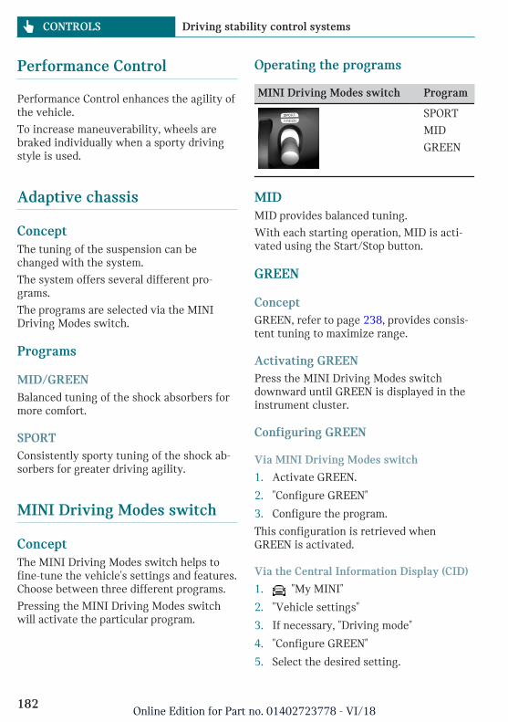
Performance Control
Performance Control enhances the agility ofthe vehicle.
To increase maneuverability, wheels arebraked individually when a sporty drivingstyle is used.
Adaptive chassis
ConceptThe tuning of the suspension can bechanged with the system.
The system offers several different pro-grams.
The programs are selected via the MINIDriving Modes switch.
Programs
MID/GREENBalanced tuning of the shock absorbers formore comfort.
SPORTConsistently sporty tuning of the shock ab-sorbers for greater driving agility.
MINI Driving Modes switch
ConceptThe MINI Driving Modes switch helps tofine-tune the vehicle's settings and features.Choose between three different programs.
Pressing the MINI Driving Modes switchwill activate the particular program.
Operating the programs
MINI Driving Modes switch Program
SPORT
MID
GREEN
MIDMID provides balanced tuning.
With each starting operation, MID is acti-vated using the Start/Stop button.
GREEN
ConceptGREEN, refer to page 238, provides consis-tent tuning to maximize range.
Activating GREENPress the MINI Driving Modes switchdownward until GREEN is displayed in theinstrument cluster.
Configuring GREEN
Via MINI Driving Modes switch
1. Activate GREEN.
2. "Configure GREEN"
3. Configure the program.
This configuration is retrieved whenGREEN is activated.
Via the Central Information Display (CID)
1. "My MINI"
2. "Vehicle settings"
3. If necessary, "Driving mode"
4. "Configure GREEN"
5. Select the desired setting.
Seite 182
CONTROLS Driving stability control systems
182Online Edition for Part no. 01402723778 - VI/18
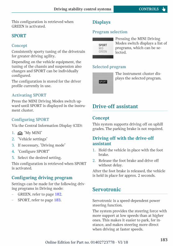
This configuration is retrieved whenGREEN is activated.
SPORT
ConceptConsistently sporty tuning of the drivetrainfor greater driving agility.
Depending on the vehicle equipment, thetuning of the chassis and suspension alsochanges and SPORT can be individuallyconfigured.
The configuration is stored for the driverprofile currently in use.
Activating SPORTPress the MINI Driving Modes switch up-ward until SPORT is displayed in the instru-ment cluster.
Configuring SPORTVia the Central Information Display (CID):
1. "My MINI"
2. "Vehicle settings"
3. If necessary, "Driving mode"
4. "Configure SPORT"
5. Select the desired setting.
This configuration is retrieved when SPORTis activated.
Configuring driving programSettings can be made for the following driv-ing programs in Driving mode:
– GREEN, refer to page 182.
– SPORT, refer to page 183.
Displays
Program selection
Pressing the MINI DrivingModes switch displays a list ofprograms, which can be se-lected.
Selected program
The instrument cluster dis-plays the selected program.
Drive-off assistant
ConceptThis system supports driving off on uphillgrades. The parking brake is not required.
Driving off with the drive-offassistant1. Hold the vehicle in place with the foot
brake.
2. Release the foot brake and drive offwithout delay.
After the foot brake is released, the vehicleis held in place for approx. 2 seconds.
Servotronic
Servotronic is a speed-dependent powersteering function.
The system provides the steering force withmore support at low speeds than at higherones. This makes it easier to park, for in-stance, and makes steering more directwhen driving at faster speeds.
Seite 183
Driving stability control systems CONTROLS
183Online Edition for Part no. 01402723778 - VI/18
Furthermore, the steering force adapts ac-cording to the driving program, so that a di-rect, sporty feel or a comfortable steeringresponse is conveyed.
Seite 184
CONTROLS Driving stability control systems
184Online Edition for Part no. 01402723778 - VI/18
Driving comfort
Vehicle features and options
This chapter describes all standard, country-specific and optional features offered withthe series. It also describes features that arenot necessarily available in your vehicle,e. g., due to the selected options or countryversions. This also applies to safety-relatedfunctions and systems. When using thesefunctions and systems, the applicable lawsand regulations must be observed.
Camera-based cruise control
ConceptUsing this system, a desired speed and adistance to a vehicle ahead can be adjustedusing the buttons on the steering wheel.
The system maintains the desired speed onclear roads. For this purpose, the vehicle ac-celerates or brakes automatically.
If a vehicle is driving ahead of you, the sys-tem adjusts the speed of your vehicle sothat the set distance to the vehicle ahead ismaintained. The speed is adjusted as far asthe given situation allows.
The distance can be adjusted in severalsteps. For safety reasons, it depends on therespective speed.
General informationA camera on the interior mirror is used todetect vehicles driving ahead.
Depending on the driving settings, the fea-tures of the cruise control can change incertain areas.
Safety information
WARNING
The system cannot serve as a substitutefor the driver’s personal judgment in as-sessing the traffic situation. Based on thelimits of the system, it cannot independ-ently react to all traffic situations. There isa risk of an accident. Adjust driving styleto traffic conditions. Watch traffic closelyand actively intervene where appropriate.
WARNING
The desired speed can be incorrectly ad-justed or called up by mistake. There is arisk of an accident. Adjust the desiredspeed to the traffic conditions. Watch traf-fic closely and actively intervene whereappropriate.
WARNING
Risk of accident due to too high speed dif-ferences to other vehicles, for instance inthe following situations:
– When fast approaching a slowly mov-ing vehicle.
– Vehicle suddenly swerving into ownlane.
– When fast approaching standing ve-hicles.
There is a risk of injuries or danger to life.Watch traffic closely and actively inter-vene where appropriate.
Seite 185
Driving comfort CONTROLS
185Online Edition for Part no. 01402723778 - VI/18
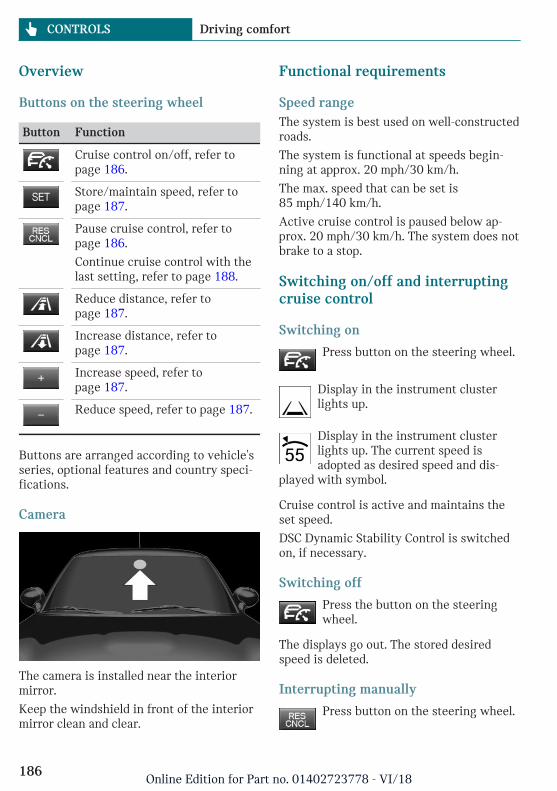
Overview
Buttons on the steering wheel
Button Function
Cruise control on/off, refer topage 186.
Store/maintain speed, refer topage 187.
Pause cruise control, refer topage 186.
Continue cruise control with thelast setting, refer to page 188.
Reduce distance, refer topage 187.
Increase distance, refer topage 187.
Increase speed, refer topage 187.
Reduce speed, refer to page 187.
Buttons are arranged according to vehicle'sseries, optional features and country speci-fications.
Camera
The camera is installed near the interiormirror.
Keep the windshield in front of the interiormirror clean and clear.
Functional requirements
Speed rangeThe system is best used on well-constructedroads.
The system is functional at speeds begin-ning at approx. 20 mph/30 km/h.
The max. speed that can be set is85 mph/140 km/h.
Active cruise control is paused below ap-prox. 20 mph/30 km/h. The system does notbrake to a stop.
Switching on/off and interruptingcruise control
Switching on
Press button on the steering wheel.
Display in the instrument clusterlights up.
Display in the instrument clusterlights up. The current speed isadopted as desired speed and dis-
played with symbol.
Cruise control is active and maintains theset speed.
DSC Dynamic Stability Control is switchedon, if necessary.
Switching off
Press the button on the steeringwheel.
The displays go out. The stored desiredspeed is deleted.
Interrupting manually
Press button on the steering wheel.
Seite 186
CONTROLS Driving comfort
186Online Edition for Part no. 01402723778 - VI/18
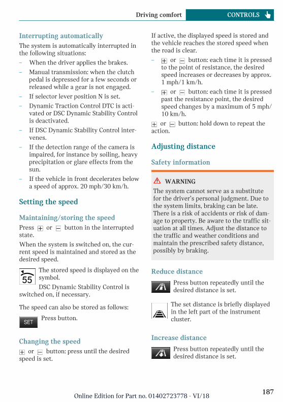
Interrupting automaticallyThe system is automatically interrupted inthe following situations:
– When the driver applies the brakes.
– Manual transmission: when the clutchpedal is depressed for a few seconds orreleased while a gear is not engaged.
– If selector lever position N is set.
– Dynamic Traction Control DTC is acti-vated or DSC Dynamic Stability Controlis deactivated.
– If DSC Dynamic Stability Control inter-venes.
– If the detection range of the camera isimpaired, for instance by soiling, heavyprecipitation or glare effects from thesun.
– If the vehicle in front decelerates belowa speed of approx. 20 mph/30 km/h.
Setting the speed
Maintaining/storing the speedPress or button in the interruptedstate.
When the system is switched on, the cur-rent speed is maintained and stored as thedesired speed.
The stored speed is displayed on thesymbol.
DSC Dynamic Stability Control isswitched on, if necessary.
The speed can also be stored as follows:
Press button.
Changing the speed or button: press until the desired
speed is set.
If active, the displayed speed is stored andthe vehicle reaches the stored speed whenthe road is clear.
– or button: each time it is pressedto the point of resistance, the desiredspeed increases or decreases by approx.1 mph/1 km/h.
– or button: each time it is pressedpast the resistance point, the desiredspeed changes by a maximum of 5 mph/10 km/h.
or button: hold down to repeat theaction.
Adjusting distance
Safety information
WARNING
The system cannot serve as a substitutefor the driver’s personal judgment. Due tothe system limits, braking can be late.There is a risk of accidents or risk of dam-age to property. Be aware to the traffic sit-uation at all times. Adjust the distance tothe traffic and weather conditions andmaintain the prescribed safety distance,possibly by braking.
Reduce distance
Press button repeatedly until thedesired distance is set.
The set distance is briefly displayedin the left part of the instrumentcluster.
Increase distance
Press button repeatedly until thedesired distance is set.
Seite 187
Driving comfort CONTROLS
187Online Edition for Part no. 01402723778 - VI/18
The set distance is briefly displayedin the left part of the instrumentcluster.
Continuing cruise control
General informationAn interrupted cruise control can be contin-ued by calling up the stored speed.
Make sure that the difference between cur-rent speed and stored speed is not too largebefore calling up the stored speed. Other-wise, unintentional braking or acceleratingmay occur.
In the following cases, the stored speedvalue is deleted and cannot be called upagain:
– When the system is switched off.
– When the ignition is switched off.
Calling up stored speed and distance
Press button with the system inter-rupted. Cruise control is continuedwith the stored values. The selected
distance is briefly displayed in the Info Dis-play.
Switching distance control on/off
Safety information
WARNING
The system does not react to traffic driv-ing ahead of you, but instead maintainsthe stored speed. There is a risk of acci-dents or risk of damage to property. Adjustthe desired speed to the traffic conditionsand brake as needed.
Switching distance control offDistance control can be switched off and onwhen driving with cruise control activated.
Press and hold this button.
Or:
Press and hold this button.
The indicator light in the instrumentcluster lights up.
To switch distance control back on, pressone of the two buttons again briefly.
After changing over distance control, aCheck Control message is displayed.
Displays in the instrument cluster
Desired speed and stored speed
In addition to the indicator light, thedesired speed is displayed in the InfoDisplay.
– Display lights up green: system is active,the display indicates the desired speed.
– Display lights up orange: system is in-terrupted, the display indicates thestored speed.
– No display: system is switched off.
If no speed is indicated, it is possible thatthe conditions necessary for operation arenot currently fulfilled.
Distance to vehicle ahead of youSelected distance from the vehicle drivingahead is briefly displayed in the left handportion of the Info Display.
Seite 188
CONTROLS Driving comfort
188Online Edition for Part no. 01402723778 - VI/18
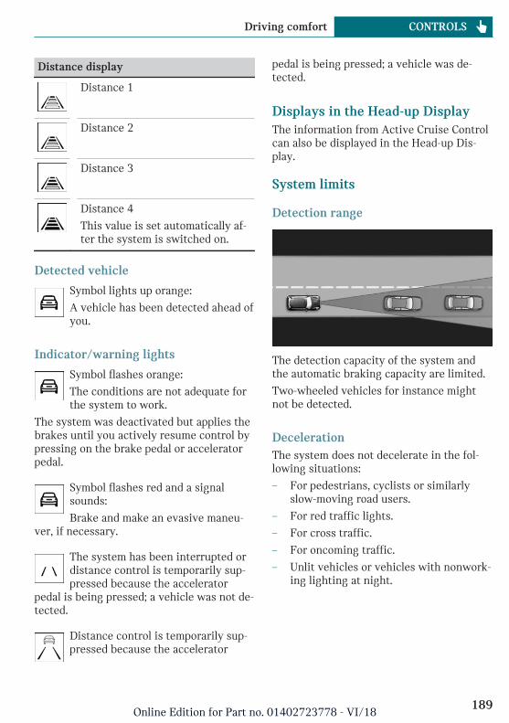
Distance display
Distance 1
Distance 2
Distance 3
Distance 4
This value is set automatically af-ter the system is switched on.
Detected vehicle
Symbol lights up orange:
A vehicle has been detected ahead ofyou.
Indicator/warning lights
Symbol flashes orange:
The conditions are not adequate forthe system to work.
The system was deactivated but applies thebrakes until you actively resume control bypressing on the brake pedal or acceleratorpedal.
Symbol flashes red and a signalsounds:
Brake and make an evasive maneu-ver, if necessary.
The system has been interrupted ordistance control is temporarily sup-pressed because the accelerator
pedal is being pressed; a vehicle was not de-tected.
Distance control is temporarily sup-pressed because the accelerator
pedal is being pressed; a vehicle was de-tected.
Displays in the Head-up DisplayThe information from Active Cruise Controlcan also be displayed in the Head-up Dis-play.
System limits
Detection range
The detection capacity of the system andthe automatic braking capacity are limited.
Two-wheeled vehicles for instance mightnot be detected.
DecelerationThe system does not decelerate in the fol-lowing situations:
– For pedestrians, cyclists or similarlyslow-moving road users.
– For red traffic lights.
– For cross traffic.
– For oncoming traffic.
– Unlit vehicles or vehicles with nonwork-ing lighting at night.
Seite 189
Driving comfort CONTROLS
189Online Edition for Part no. 01402723778 - VI/18
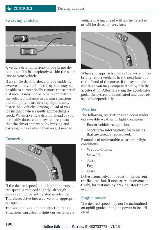
Swerving vehicles
A vehicle driving in front of you is not de-tected until it is completely within the samelane as your vehicle.
If a vehicle driving ahead of you suddenlyswerves into your lane, the system may notbe able to automatically restore the selecteddistance. It may not be possible to restorethe selected distance in certain situations,including if you are driving significantlyfaster than vehicles driving ahead of you,for instance when rapidly approaching atruck. When a vehicle driving ahead of youis reliably detected, the system requeststhat the driver intervene by braking andcarrying out evasive maneuvers, if needed.
Cornering
If the desired speed is too high for a curve,the speed is reduced slightly, althoughcurves cannot be anticipated in advance.Therefore, drive into a curve at an appropri-ate speed.
The system has a limited detection range.Situations can arise in tight curves where a
vehicle driving ahead will not be detectedor will be detected very late.
When you approach a curve the system maybriefly report vehicles in the next lane dueto the bend of the curve. If the system de-celerates you may compensate it by brieflyaccelerating. After releasing the acceleratorpedal the system is reactivated and controlsspeed independently.
WeatherThe following restrictions can occur underunfavorable weather or light conditions:
– Poorer vehicle recognition.
– Short-term interruptions for vehiclesthat are already recognized.
Examples of unfavorable weather or lightconditions:
– Wet conditions.
– Snowfall.
– Slush.
– Fog.
– Glare.
Drive attentively, and react to the currenttraffic situation. If necessary, intervene ac-tively, for instance by braking, steering orevading.
Engine powerThe desired speed may not be maintainedon uphill grades if engine power is insuffi-cient.
Seite 190
CONTROLS Driving comfort
190Online Edition for Part no. 01402723778 - VI/18
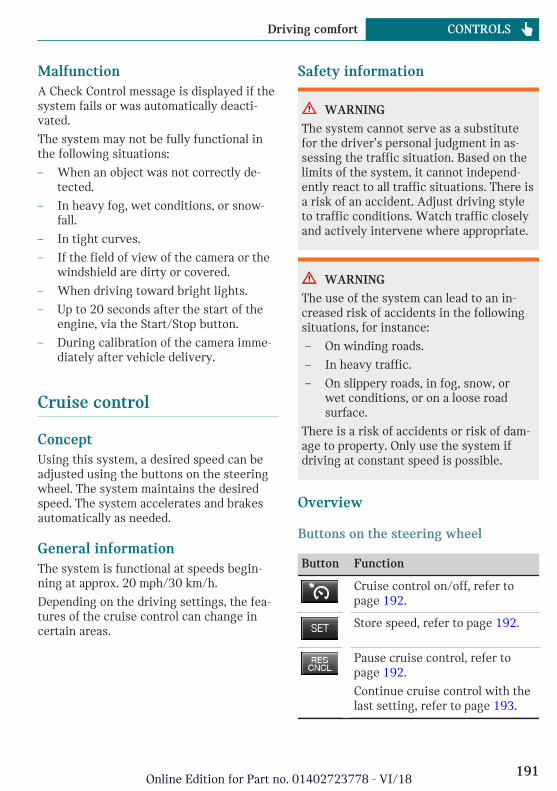
MalfunctionA Check Control message is displayed if thesystem fails or was automatically deacti-vated.
The system may not be fully functional inthe following situations:
– When an object was not correctly de-tected.
– In heavy fog, wet conditions, or snow-fall.
– In tight curves.
– If the field of view of the camera or thewindshield are dirty or covered.
– When driving toward bright lights.
– Up to 20 seconds after the start of theengine, via the Start/Stop button.
– During calibration of the camera imme-diately after vehicle delivery.
Cruise control
ConceptUsing this system, a desired speed can beadjusted using the buttons on the steeringwheel. The system maintains the desiredspeed. The system accelerates and brakesautomatically as needed.
General informationThe system is functional at speeds begin-ning at approx. 20 mph/30 km/h.
Depending on the driving settings, the fea-tures of the cruise control can change incertain areas.
Safety information
WARNING
The system cannot serve as a substitutefor the driver’s personal judgment in as-sessing the traffic situation. Based on thelimits of the system, it cannot independ-ently react to all traffic situations. There isa risk of an accident. Adjust driving styleto traffic conditions. Watch traffic closelyand actively intervene where appropriate.
WARNING
The use of the system can lead to an in-creased risk of accidents in the followingsituations, for instance:
– On winding roads.
– In heavy traffic.
– On slippery roads, in fog, snow, orwet conditions, or on a loose roadsurface.
There is a risk of accidents or risk of dam-age to property. Only use the system ifdriving at constant speed is possible.
Overview
Buttons on the steering wheel
Button Function
Cruise control on/off, refer topage 192.
Store speed, refer to page 192.
Pause cruise control, refer topage 192.
Continue cruise control with thelast setting, refer to page 193.
Seite 191
Driving comfort CONTROLS
191Online Edition for Part no. 01402723778 - VI/18
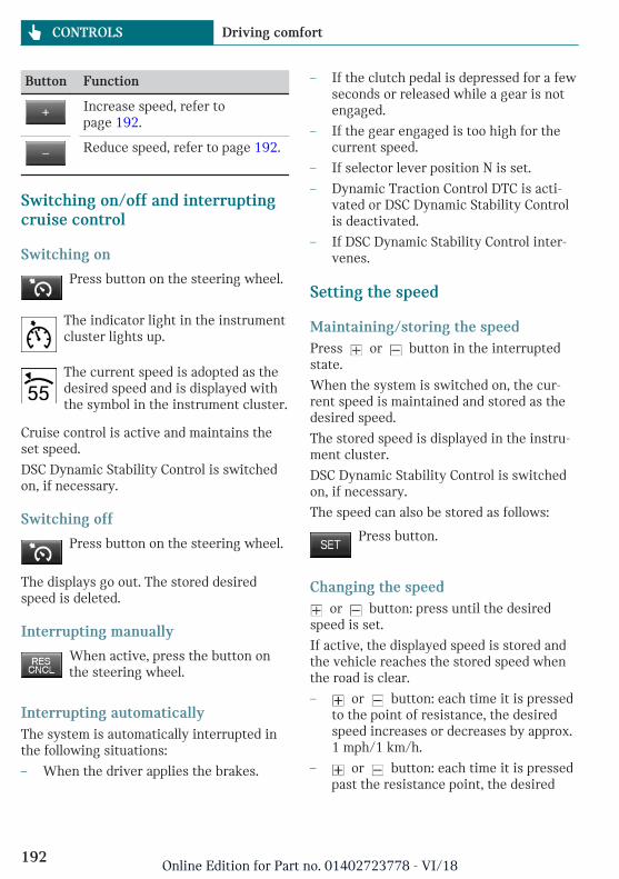
Button Function
Increase speed, refer topage 192.
Reduce speed, refer to page 192.
Switching on/off and interruptingcruise control
Switching on
Press button on the steering wheel.
The indicator light in the instrumentcluster lights up.
The current speed is adopted as thedesired speed and is displayed withthe symbol in the instrument cluster.
Cruise control is active and maintains theset speed.
DSC Dynamic Stability Control is switchedon, if necessary.
Switching off
Press button on the steering wheel.
The displays go out. The stored desiredspeed is deleted.
Interrupting manually
When active, press the button onthe steering wheel.
Interrupting automaticallyThe system is automatically interrupted inthe following situations:
– When the driver applies the brakes.
– If the clutch pedal is depressed for a fewseconds or released while a gear is notengaged.
– If the gear engaged is too high for thecurrent speed.
– If selector lever position N is set.
– Dynamic Traction Control DTC is acti-vated or DSC Dynamic Stability Controlis deactivated.
– If DSC Dynamic Stability Control inter-venes.
Setting the speed
Maintaining/storing the speedPress or button in the interruptedstate.
When the system is switched on, the cur-rent speed is maintained and stored as thedesired speed.
The stored speed is displayed in the instru-ment cluster.
DSC Dynamic Stability Control is switchedon, if necessary.
The speed can also be stored as follows:
Press button.
Changing the speed or button: press until the desired
speed is set.
If active, the displayed speed is stored andthe vehicle reaches the stored speed whenthe road is clear.
– or button: each time it is pressedto the point of resistance, the desiredspeed increases or decreases by approx.1 mph/1 km/h.
– or button: each time it is pressedpast the resistance point, the desired
Seite 192
CONTROLS Driving comfort
192Online Edition for Part no. 01402723778 - VI/18
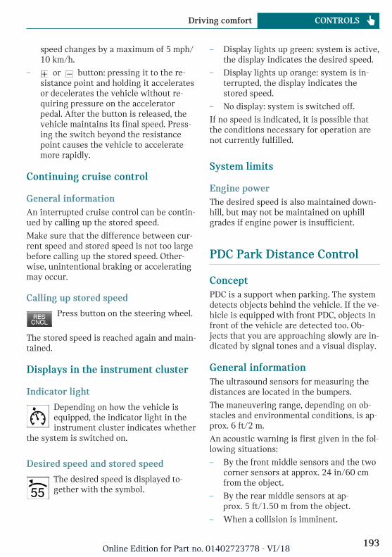
speed changes by a maximum of 5 mph/10 km/h.
– or button: pressing it to the re-sistance point and holding it acceleratesor decelerates the vehicle without re-quiring pressure on the acceleratorpedal. After the button is released, thevehicle maintains its final speed. Press-ing the switch beyond the resistancepoint causes the vehicle to acceleratemore rapidly.
Continuing cruise control
General informationAn interrupted cruise control can be contin-ued by calling up the stored speed.
Make sure that the difference between cur-rent speed and stored speed is not too largebefore calling up the stored speed. Other-wise, unintentional braking or acceleratingmay occur.
Calling up stored speed
Press button on the steering wheel.
The stored speed is reached again and main-tained.
Displays in the instrument cluster
Indicator light
Depending on how the vehicle isequipped, the indicator light in theinstrument cluster indicates whether
the system is switched on.
Desired speed and stored speed
The desired speed is displayed to-gether with the symbol.
– Display lights up green: system is active,the display indicates the desired speed.
– Display lights up orange: system is in-terrupted, the display indicates thestored speed.
– No display: system is switched off.
If no speed is indicated, it is possible thatthe conditions necessary for operation arenot currently fulfilled.
System limits
Engine powerThe desired speed is also maintained down-hill, but may not be maintained on uphillgrades if engine power is insufficient.
PDC Park Distance Control
ConceptPDC is a support when parking. The systemdetects objects behind the vehicle. If the ve-hicle is equipped with front PDC, objects infront of the vehicle are detected too. Ob-jects that you are approaching slowly are in-dicated by signal tones and a visual display.
General informationThe ultrasound sensors for measuring thedistances are located in the bumpers.
The maneuvering range, depending on ob-stacles and environmental conditions, is ap-prox. 6 ft/2 m.
An acoustic warning is first given in the fol-lowing situations:
– By the front middle sensors and the twocorner sensors at approx. 24 in/60 cmfrom the object.
– By the rear middle sensors at ap-prox. 5 ft/1.50 m from the object.
– When a collision is imminent.
Seite 193
Driving comfort CONTROLS
193Online Edition for Part no. 01402723778 - VI/18
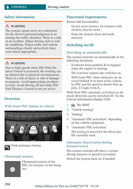
Safety information
WARNING
The system cannot serve as a substitutefor the driver’s personal judgment in as-sessing the traffic situation. There is a riskof an accident. Adjust driving style to traf-fic conditions. Watch traffic and vehiclesurroundings closely and actively inter-vene where appropriate.
WARNING
Due to high speeds when PDC Park Dis-tance Control is activated, the warning canbe delayed due to physical circumstances.There is a risk of injury or risk of damageto property. Avoid approaching an objecttoo fast. Avoid driving off fast while PDCPark Distance Control is not yet active.
Overview
With front PDC: button in vehicle
Park assistance button
Ultrasound sensors
Ultrasound sensors of thePDC, for instance in the bump-ers.
Functional requirementsEnsure full functionality:
– Do not cover sensors, for instance withstickers, bicycle racks.
– Keep the sensors clean and unob-structed.
Switching on/off
Switching on automaticallyThe system switches on automatically in thefollowing situations:
– If selector lever position R is engagedwhen the engine is running.
The rearview camera also switches on.
– With front PDC: when obstacles are de-tected behind or in front of the vehicleby PDC and the speed is slower than ap-prox. 2.5 mph/4 km/h.
With front PDC: automatic activation on ob-stacle detection can be switched off. Via theCentral Information Display (CID):
1. "My MINI"
2. "Vehicle settings"
3. "Parking"
4. "Automatic PDC activation": dependingon the vehicle equipment.
5. "Automatic PDC activation"
The setting is stored for the driver pro-file currently used.
Automatic deactivation duringforward travelThe system switches off when a certaindriving distance or speed is exceeded.
Switch the system back on, if needed.
Seite 194
CONTROLS Driving comfort
194Online Edition for Part no. 01402723778 - VI/18
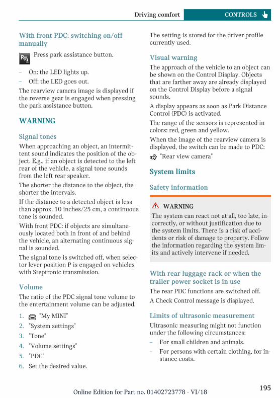
With front PDC: switching on/offmanually
Press park assistance button.
– On: the LED lights up.
– Off: the LED goes out.
The rearview camera image is displayed ifthe reverse gear is engaged when pressingthe park assistance button.
WARNING
Signal tonesWhen approaching an object, an intermit-tent sound indicates the position of the ob-ject. E.g., if an object is detected to the leftrear of the vehicle, a signal tone soundsfrom the left rear speaker.
The shorter the distance to the object, theshorter the intervals.
If the distance to a detected object is lessthan approx. 10 inches/25 cm, a continuoustone is sounded.
With front PDC: if objects are simultane-ously located both in front of and behindthe vehicle, an alternating continuous sig-nal is sounded.
The signal tone is switched off, when selec-tor lever position P is engaged on vehicleswith Steptronic transmission.
VolumeThe ratio of the PDC signal tone volume tothe entertainment volume can be adjusted.
1. "My MINI"
2. "System settings"
3. "Tone"
4. "Volume settings"
5. "PDC"
6. Set the desired value.
The setting is stored for the driver profilecurrently used.
Visual warningThe approach of the vehicle to an object canbe shown on the Control Display. Objectsthat are farther away are already displayedon the Control Display before a signalsounds.
A display appears as soon as Park DistanceControl (PDC) is activated.
The range of the sensors is represented incolors: red, green and yellow.
When the image of the rearview camera isdisplayed, the switch can be made to PDC:
"Rear view camera"
System limits
Safety information
WARNING
The system can react not at all, too late, in-correctly, or without justification due tothe system limits. There is a risk of acci-dents or risk of damage to property. Followthe information regarding the system lim-its and actively intervene if needed.
With rear luggage rack or when thetrailer power socket is in useThe rear PDC functions are switched off.
A Check Control message is displayed.
Limits of ultrasonic measurementUltrasonic measuring might not functionunder the following circumstances:
– For small children and animals.
– For persons with certain clothing, for in-stance coats.
Seite 195
Driving comfort CONTROLS
195Online Edition for Part no. 01402723778 - VI/18
– With external interference of the ultra-sound, for instance from passing vehi-cles or loud machines.
– When sensors are dirty, iced over, dam-aged or out of position.
– If cargo protrudes.
– Under certain weather conditions suchas high relative humidity, wet condi-tions, snowfall, extreme heat, or strongwind.
– With tow bars and trailer couplings ofother vehicles.
– With thin or wedge-shaped objects.
– With moving objects.
– With elevated, protruding objects suchas ledges or cargo.
– With objects with corners and sharpedges.
– With objects with a fine surface struc-ture such as fences.
– For objects with porous surfaces.
– Low objects already displayed, for in-stance curbs, can move into the blindarea of the sensors before or after a con-tinuous tone sounds.
False warningsThe system may issue a warning under thefollowing conditions even though there isno obstacle within the detection range:
– In heavy rain.
– When sensors are very dirty or coveredwith ice.
– When sensors are covered in snow.
– On rough road surfaces.
– On uneven surfaces, such as speedbumps.
– In large buildings with right angles andsmooth walls, for instance in under-ground garages.
– In automatic vehicle washes.
– Due to heavy exhaust.
– Due to other ultrasound sources, for in-stance sweeping machines, high pres-sure steam cleaners or neon lights.
The malfunction is signaled by a contin-uous tone alternating between the frontand rear speakers. As soon as the mal-function due to other ultrasound sourcesis no longer present, the system is againfully functional.
With front PDC: to reduce false alarms,switch off automatic PDC activation on ob-stacle detection, for instance in vehiclewashes; see Switching on/off.
MalfunctionA Check Control message is displayed in theinstrument cluster.
Red symbol is displayed, and therange of the sensors is dimmed onthe Control Display.
PDC has failed. Have the system checked bya dealer’s service center or another quali-fied service center or repair shop.
Rearview camera
ConceptThe rearview camera provides assistance inparking and maneuvering backwards. Thearea behind the vehicle is shown on theControl Display.
Safety information
WARNING
The system cannot serve as a substitutefor the driver’s personal judgment in as-sessing the traffic situation. There is a riskof an accident. Adjust driving style to traf-fic conditions. Watch traffic and vehicle
Seite 196
CONTROLS Driving comfort
196Online Edition for Part no. 01402723778 - VI/18
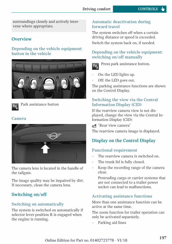
surroundings closely and actively inter-vene where appropriate.
Overview
Depending on the vehicle equipment:button in the vehicle
Park assistance button
Camera
The camera lens is located in the handle ofthe tailgate.
The image quality may be impaired by dirt.If necessary, clean the camera lens.
Switching on/off
Switching on automaticallyThe system is switched on automatically ifselector lever position R is engaged whenthe engine is running.
Automatic deactivation duringforward travelThe system switches off when a certaindriving distance or speed is exceeded.
Switch the system back on, if needed.
Depending on the vehicle equipment:switching on/off manually
Press park assistance button.
– On: the LED lights up.
– Off: the LED goes out.
The parking assistance functions are shownon the Control Display.
Switching the view via the CentralInformation Display (CID)If the rearview camera view is not dis-played, change the view via the Central In-formation Display (CID):
"Rear view camera"
The rearview camera image is displayed.
Display on the Control Display
Functional requirement– The rearview camera is switched on.
– The trunk lid is fully closed.
– Keep the recording range of the cameraclear.
Protruding cargo or carrier systems thatare not connected to a trailer powersocket can lead to malfunctions.
Activating assistance functionsMore than one assistance function can beactive at the same time.
The zoom function for trailer operation canonly be activated separately.
– Parking aid lines
Seite 197
Driving comfort CONTROLS
197Online Edition for Part no. 01402723778 - VI/18
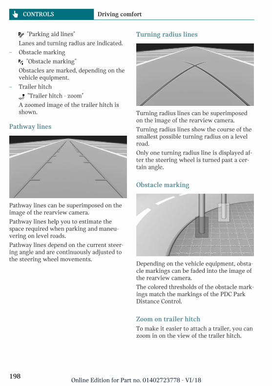
"Parking aid lines"
Lanes and turning radius are indicated.
– Obstacle marking
"Obstacle marking"
Obstacles are marked, depending on thevehicle equipment.
– Trailer hitch
"Trailer hitch - zoom"
A zoomed image of the trailer hitch isshown.
Pathway lines
Pathway lines can be superimposed on theimage of the rearview camera.
Pathway lines help you to estimate thespace required when parking and maneu-vering on level roads.
Pathway lines depend on the current steer-ing angle and are continuously adjusted tothe steering wheel movements.
Turning radius lines
Turning radius lines can be superimposedon the image of the rearview camera.
Turning radius lines show the course of thesmallest possible turning radius on a levelroad.
Only one turning radius line is displayed af-ter the steering wheel is turned past a cer-tain angle.
Obstacle marking
Depending on the vehicle equipment, obsta-cle markings can be faded into the image ofthe rearview camera.
The colored thresholds of the obstacle mark-ings match the markings of the PDC ParkDistance Control.
Zoom on trailer hitchTo make it easier to attach a trailer, you canzoom in on the view of the trailer hitch.
Seite 198
CONTROLS Driving comfort
198Online Edition for Part no. 01402723778 - VI/18
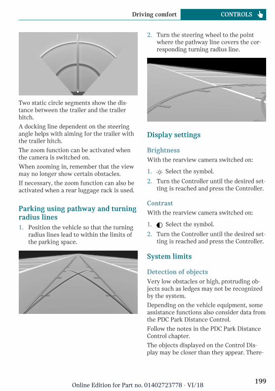
Two static circle segments show the dis-tance between the trailer and the trailerhitch.
A docking line dependent on the steeringangle helps with aiming for the trailer withthe trailer hitch.
The zoom function can be activated whenthe camera is switched on.
When zooming in, remember that the viewmay no longer show certain obstacles.
If necessary, the zoom function can also beactivated when a rear luggage rack is used.
Parking using pathway and turningradius lines1. Position the vehicle so that the turning
radius lines lead to within the limits ofthe parking space.
2. Turn the steering wheel to the pointwhere the pathway line covers the cor-responding turning radius line.
Display settings
BrightnessWith the rearview camera switched on:
1. Select the symbol.
2. Turn the Controller until the desired set-ting is reached and press the Controller.
ContrastWith the rearview camera switched on:
1. Select the symbol.
2. Turn the Controller until the desired set-ting is reached and press the Controller.
System limits
Detection of objectsVery low obstacles or high, protruding ob-jects such as ledges may not be recognizedby the system.
Depending on the vehicle equipment, someassistance functions also consider data fromthe PDC Park Distance Control.
Follow the notes in the PDC Park DistanceControl chapter.
The objects displayed on the Control Dis-play may be closer than they appear. There-
Seite 199
Driving comfort CONTROLS
199Online Edition for Part no. 01402723778 - VI/18
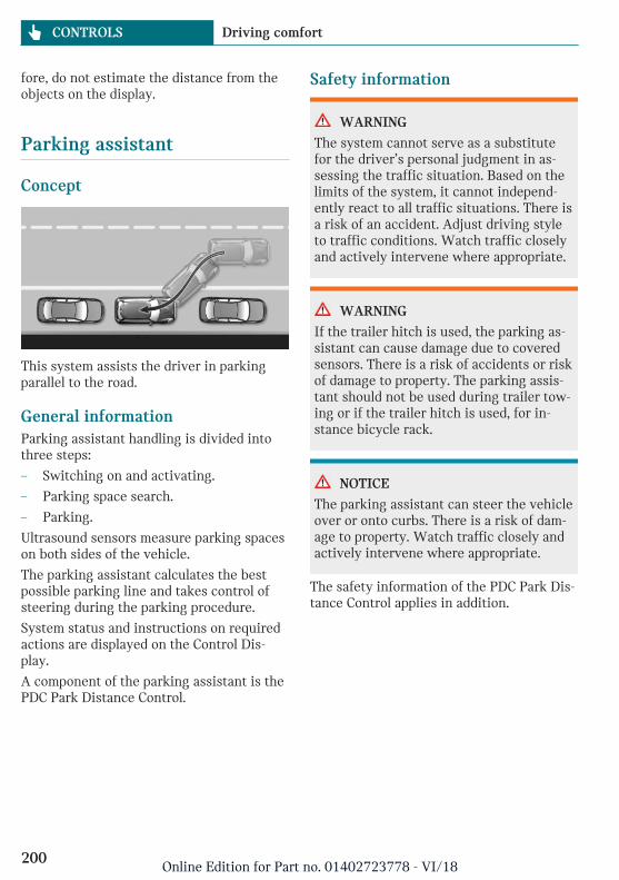
fore, do not estimate the distance from theobjects on the display.
Parking assistant
Concept
This system assists the driver in parkingparallel to the road.
General informationParking assistant handling is divided intothree steps:
– Switching on and activating.
– Parking space search.
– Parking.
Ultrasound sensors measure parking spaceson both sides of the vehicle.
The parking assistant calculates the bestpossible parking line and takes control ofsteering during the parking procedure.
System status and instructions on requiredactions are displayed on the Control Dis-play.
A component of the parking assistant is thePDC Park Distance Control.
Safety information
WARNING
The system cannot serve as a substitutefor the driver’s personal judgment in as-sessing the traffic situation. Based on thelimits of the system, it cannot independ-ently react to all traffic situations. There isa risk of an accident. Adjust driving styleto traffic conditions. Watch traffic closelyand actively intervene where appropriate.
WARNING
If the trailer hitch is used, the parking as-sistant can cause damage due to coveredsensors. There is a risk of accidents or riskof damage to property. The parking assis-tant should not be used during trailer tow-ing or if the trailer hitch is used, for in-stance bicycle rack.
NOTICE
The parking assistant can steer the vehicleover or onto curbs. There is a risk of dam-age to property. Watch traffic closely andactively intervene where appropriate.
The safety information of the PDC Park Dis-tance Control applies in addition.
Seite 200
CONTROLS Driving comfort
200Online Edition for Part no. 01402723778 - VI/18
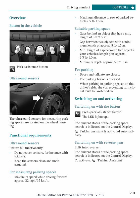
Overview
Button in the vehicle
Park assistance button
Ultrasound sensors
The ultrasound sensors for measuring park-ing spaces are located on the wheel hous-ing.
Functional requirements
Ultrasound sensorsEnsure full functionality:
– Do not cover sensors, for instance withstickers.
– Keep the sensors clean and unob-structed.
For measuring parking spaces– Maximum speed while driving forward
approx. 22 mph/35 km/h.
– Maximum distance to row of parked ve-hicles: 5 ft/1.5 m.
Suitable parking space– Gaps behind an object that has a min.
length of 5 ft/1.5 m.
– Gap between two objects with a mini-mum length of approx. 5 ft/1.5 m.
– Min. length of gap between two objects:your vehicle's length plus approx.3.3 ft/1.0 m.
– Minimum depth: approx. 5 ft/1.5 m.
For parking– Doors and tailgate are closed.
– The parking brake is released.
– When parking in parking spaces on thedriver's side, the corresponding turn sig-nal must be switched on.
Switching on and activating
Switching on with the button
Press park assistance button.
The LED lights up.
The current status of the parking spacesearch is indicated on the Control Display.
Parking assistant is activated automati-cally.
Switching on with reverse gearShift into reverse.
The current status of the parking spacesearch is indicated on the Control Display.
To activate: "Parking Assistant"
Seite 201
Driving comfort CONTROLS
201Online Edition for Part no. 01402723778 - VI/18
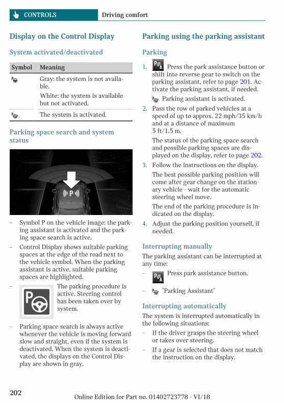
Display on the Control Display
System activated/deactivated
Symbol Meaning
Gray: the system is not availa-ble.
White: the system is availablebut not activated.
The system is activated.
Parking space search and systemstatus
– Symbol P on the vehicle image: the park-ing assistant is activated and the park-ing space search is active.
– Control Display shows suitable parkingspaces at the edge of the road next tothe vehicle symbol. When the parkingassistant is active, suitable parkingspaces are highlighted.
– The parking procedure isactive. Steering controlhas been taken over bysystem.
– Parking space search is always activewhenever the vehicle is moving forwardslow and straight, even if the system isdeactivated. When the system is deacti-vated, the displays on the Control Dis-play are shown in gray.
Parking using the parking assistant
Parking
1. Press the park assistance button orshift into reverse gear to switch on theparking assistant, refer to page 201. Ac-tivate the parking assistant, if needed.
Parking assistant is activated.
2. Pass the row of parked vehicles at aspeed of up to approx. 22 mph/35 km/hand at a distance of maximum5 ft/1.5 m.
The status of the parking space searchand possible parking spaces are dis-played on the display, refer to page 202.
3. Follow the instructions on the display.
The best possible parking position willcome after gear change on the station-ary vehicle - wait for the automaticsteering wheel move.
The end of the parking procedure is in-dicated on the display.
4. Adjust the parking position yourself, ifneeded.
Interrupting manuallyThe parking assistant can be interrupted atany time:
– Press park assistance button.
– "Parking Assistant"
Interrupting automaticallyThe system is interrupted automatically inthe following situations:
– If the driver grasps the steering wheelor takes over steering.
– If a gear is selected that does not matchthe instruction on the display.
Seite 202
CONTROLS Driving comfort
202Online Edition for Part no. 01402723778 - VI/18
– If the vehicle speed exceeds approx.6 mph/10 km/h.
– Possibly on snow-covered or slipperyroad surfaces.
– If a maximum number of parking at-tempts or the time taken for parking isexceeded.
– If the PDC Park Distance Control dis-plays clearances that are too small.
– When switching into other functions ofthe radio.
A Check Control message is displayed.
ResumingAn interrupted parking procedure can becontinued, if needed.
Reactivate the parking assistant, refer topage 201, and follow the instructions on thedisplay.
Switching offThe system can be switched off as follows:
– Press park assistance button.
– Switching off the ignition.
System limits
Safety information
WARNING
The system can react not at all, too late, in-correctly, or without justification due tothe system limits. There is a risk of acci-dents or risk of damage to property. Followthe information regarding the system lim-its and actively intervene if needed.
No parking assistanceThe parking assistant does not offer assis-tance in the following situations:
– In tight curves.
– With mounted rear luggage rack.
Functional limitationsThe system may not be fully functional inthe following situations:
– On bumpy road surfaces such as gravelroads.
– On slippery ground.
– With accumulations of leaves/snow inthe parking space.
– With a mounted emergency wheel.
– With ditches or edges, for instance anedge of a port.
Limits of ultrasonic measurementUltrasonic measuring might not functionunder the following circumstances:
– For small children and animals.
– For persons with certain clothing, for in-stance coats.
– With external interference of the ultra-sound, for instance from passing vehi-cles or loud machines.
– When sensors are dirty, iced over, dam-aged or out of position.
– If cargo protrudes.
– Under certain weather conditions suchas high relative humidity, wet condi-tions, snowfall, extreme heat, or strongwind.
– With tow bars and trailer couplings ofother vehicles.
– With thin or wedge-shaped objects.
– With moving objects.
– With elevated, protruding objects suchas ledges or cargo.
– With objects with corners and sharpedges.
Seite 203
Driving comfort CONTROLS
203Online Edition for Part no. 01402723778 - VI/18
– With objects with a fine surface struc-ture such as fences.
– For objects with porous surfaces.
– Low objects already displayed, for in-stance curbs, can move into the blindarea of the sensors before or after a con-tinuous tone sounds.
– The parking assistant may identify park-ing spaces that are not suitable for park-ing.
Tire sizeThe parking position may vary dependingon the tire size.
MalfunctionA Check Control message is displayed.
The parking assistant failed. Have the sys-tem checked by a dealer’s service center oranother qualified service center or repairshop.
Seite 204
CONTROLS Driving comfort
204Online Edition for Part no. 01402723778 - VI/18
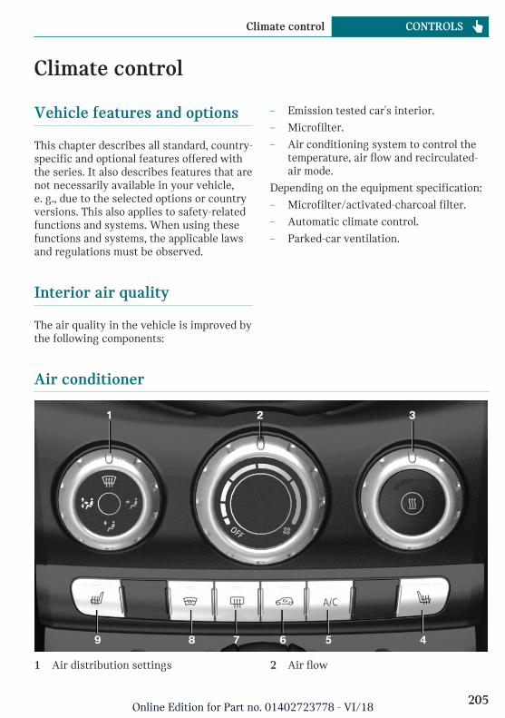
Climate control
Vehicle features and options
This chapter describes all standard, country-specific and optional features offered withthe series. It also describes features that arenot necessarily available in your vehicle,e. g., due to the selected options or countryversions. This also applies to safety-relatedfunctions and systems. When using thesefunctions and systems, the applicable lawsand regulations must be observed.
Interior air quality
The air quality in the vehicle is improved bythe following components:
– Emission tested car's interior.
– Microfilter.
– Air conditioning system to control thetemperature, air flow and recirculated-air mode.
Depending on the equipment specification:
– Microfilter/activated-charcoal filter.
– Automatic climate control.
– Parked-car ventilation.
Air conditioner
1 Air distribution settings 2 Air flow
Seite 205
Climate control CONTROLS
205Online Edition for Part no. 01402723778 - VI/18
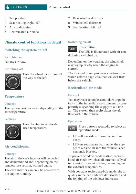
3 Temperature
4 Seat heating, right 97
5 Air conditioning
6 Recirculated-air mode
7 Rear window defroster
8 Windshield defroster
9 Seat heating, left 97
Climate control functions in detail
Switching the system on/off
Switching on
Set any air flow.
Switching off
Turn the wheel for air flow allthe way to the left.
Temperature
Concept
The system heats or cools, depending on theset temperature.
Settings
Turn the ring to set the de-sired temperature.
Air conditioning
Concept
The air in the car's interior will be cooledand dehumidified and, depending on thetemperature setting, warmed again.
The car's interior can only be cooled withthe engine running.
Switching on/off
Press button.
The LED is illuminated with air con-ditioning switched on.
Depending on the weather, the windshieldmay fog up briefly when the engine isstarted.
The air conditioner produces condensationwater, refer to page 235, that will exit frombelow the vehicle.
Recirculated-air mode
Concept
You may react to unpleasant odors or pollu-tants in the immediate environment by tem-porarily suspending the supply of outsideair. The system then recirculates the airflow within the vehicle.
Operation
Press button repeatedly to select anoperating mode:
– LED off: outside air flows in continu-ously.
– LED on, recirculated-air mode: the sup-ply of outside air into the vehicle is per-manently blocked.
To prevent window condensation, recircu-lated-air mode switches off automatically af-ter a certain amount of time, depending onthe external temperature.
With constant recirculated-air mode, the airquality in the car's interior deteriorates andthe fogging of the windows increases.
Seite 206
CONTROLS Climate control
206Online Edition for Part no. 01402723778 - VI/18
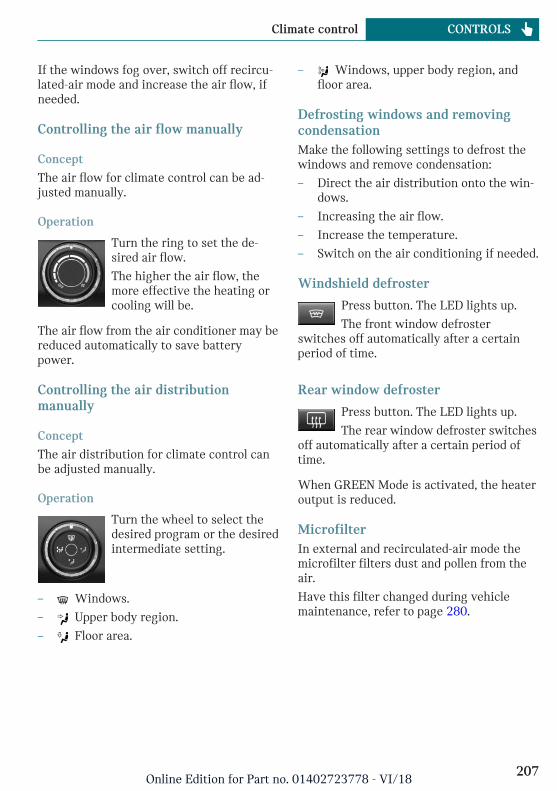
If the windows fog over, switch off recircu-lated-air mode and increase the air flow, ifneeded.
Controlling the air flow manually
Concept
The air flow for climate control can be ad-justed manually.
Operation
Turn the ring to set the de-sired air flow.
The higher the air flow, themore effective the heating orcooling will be.
The air flow from the air conditioner may bereduced automatically to save batterypower.
Controlling the air distributionmanually
Concept
The air distribution for climate control canbe adjusted manually.
Operation
Turn the wheel to select thedesired program or the desiredintermediate setting.
– Windows.
– Upper body region.
– Floor area.
– Windows, upper body region, andfloor area.
Defrosting windows and removingcondensationMake the following settings to defrost thewindows and remove condensation:
– Direct the air distribution onto the win-dows.
– Increasing the air flow.
– Increase the temperature.
– Switch on the air conditioning if needed.
Windshield defroster
Press button. The LED lights up.
The front window defrosterswitches off automatically after a certainperiod of time.
Rear window defroster
Press button. The LED lights up.
The rear window defroster switchesoff automatically after a certain period oftime.
When GREEN Mode is activated, the heateroutput is reduced.
MicrofilterIn external and recirculated-air mode themicrofilter filters dust and pollen from theair.
Have this filter changed during vehiclemaintenance, refer to page 280.
Seite 207
Climate control CONTROLS
207Online Edition for Part no. 01402723778 - VI/18
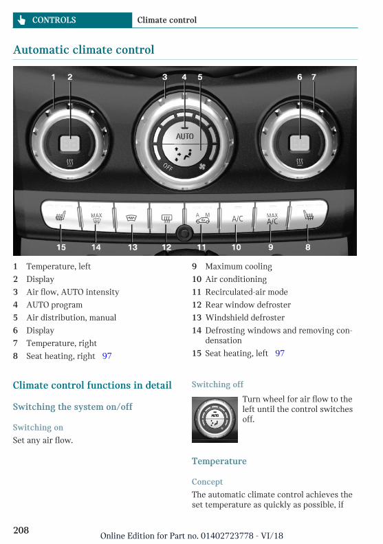
Automatic climate control
1 Temperature, left
2 Display
3 Air flow, AUTO intensity
4 AUTO program
5 Air distribution, manual
6 Display
7 Temperature, right
8 Seat heating, right 97
9 Maximum cooling
10 Air conditioning
11 Recirculated-air mode
12 Rear window defroster
13 Windshield defroster
14 Defrosting windows and removing con-densation
15 Seat heating, left 97
Climate control functions in detail
Switching the system on/off
Switching on
Set any air flow.
Switching off
Turn wheel for air flow to theleft until the control switchesoff.
Temperature
Concept
The automatic climate control achieves theset temperature as quickly as possible, if
Seite 208
CONTROLS Climate control
208Online Edition for Part no. 01402723778 - VI/18
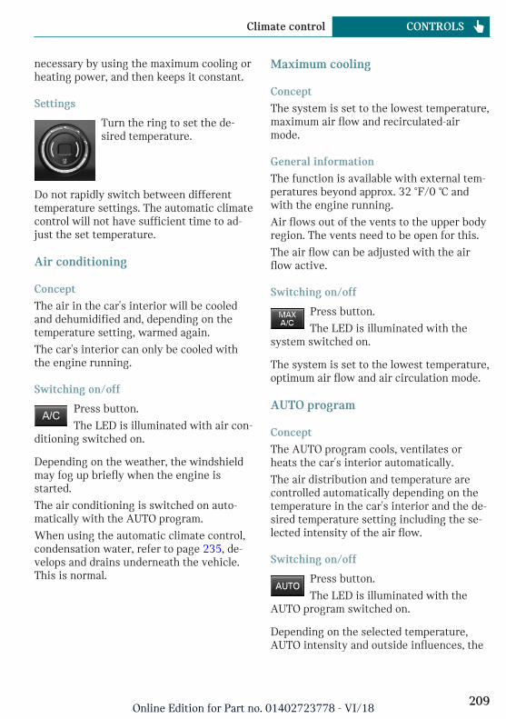
necessary by using the maximum cooling orheating power, and then keeps it constant.
Settings
Turn the ring to set the de-sired temperature.
Do not rapidly switch between differenttemperature settings. The automatic climatecontrol will not have sufficient time to ad-just the set temperature.
Air conditioning
Concept
The air in the car's interior will be cooledand dehumidified and, depending on thetemperature setting, warmed again.
The car's interior can only be cooled withthe engine running.
Switching on/off
Press button.
The LED is illuminated with air con-ditioning switched on.
Depending on the weather, the windshieldmay fog up briefly when the engine isstarted.
The air conditioning is switched on auto-matically with the AUTO program.
When using the automatic climate control,condensation water, refer to page 235, de-velops and drains underneath the vehicle.This is normal.
Maximum cooling
Concept
The system is set to the lowest temperature,maximum air flow and recirculated-airmode.
General information
The function is available with external tem-peratures beyond approx. 32 ℉/0 ℃ andwith the engine running.
Air flows out of the vents to the upper bodyregion. The vents need to be open for this.
The air flow can be adjusted with the airflow active.
Switching on/off
Press button.
The LED is illuminated with thesystem switched on.
The system is set to the lowest temperature,optimum air flow and air circulation mode.
AUTO program
Concept
The AUTO program cools, ventilates orheats the car's interior automatically.
The air distribution and temperature arecontrolled automatically depending on thetemperature in the car's interior and the de-sired temperature setting including the se-lected intensity of the air flow.
Switching on/off
Press button.
The LED is illuminated with theAUTO program switched on.
Depending on the selected temperature,AUTO intensity and outside influences, the
Seite 209
Climate control CONTROLS
209Online Edition for Part no. 01402723778 - VI/18
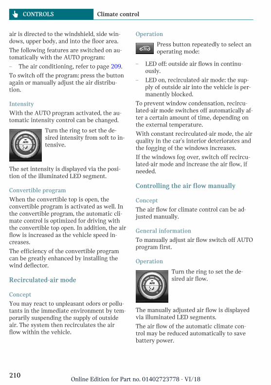
air is directed to the windshield, side win-dows, upper body, and into the floor area.
The following features are switched on au-tomatically with the AUTO program:
– The air conditioning, refer to page 209.
To switch off the program: press the buttonagain or manually adjust the air distribu-tion.
Intensity
With the AUTO program activated, the au-tomatic intensity control can be changed.
Turn the ring to set the de-sired intensity from soft to in-tensive.
The set intensity is displayed via the posi-tion of the illuminated LED segment.
Convertible program
When the convertible top is open, theconvertible program is activated as well. Inthe convertible program, the automatic cli-mate control is optimized for driving withthe convertible top open. In addition, the airflow is increased as the vehicle speed in-creases.
The efficiency of the convertible programcan be greatly enhanced by installing thewind deflector.
Recirculated-air mode
Concept
You may react to unpleasant odors or pollu-tants in the immediate environment by tem-porarily suspending the supply of outsideair. The system then recirculates the airflow within the vehicle.
Operation
Press button repeatedly to select anoperating mode:
– LED off: outside air flows in continu-ously.
– LED on, recirculated-air mode: the sup-ply of outside air into the vehicle is per-manently blocked.
To prevent window condensation, recircu-lated-air mode switches off automatically af-ter a certain amount of time, depending onthe external temperature.
With constant recirculated-air mode, the airquality in the car's interior deteriorates andthe fogging of the windows increases.
If the windows fog over, switch off recircu-lated-air mode and increase the air flow, ifneeded.
Controlling the air flow manually
Concept
The air flow for climate control can be ad-justed manually.
General information
To manually adjust air flow switch off AUTOprogram first.
Operation
Turn the ring to set the de-sired air flow.
The manually adjusted air flow is displayedvia illuminated LED segments.
The air flow of the automatic climate con-trol may be reduced automatically to savebattery power.
Seite 210
CONTROLS Climate control
210Online Edition for Part no. 01402723778 - VI/18
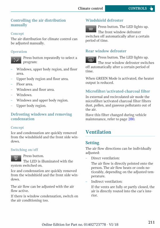
Controlling the air distributionmanually
Concept
The air distribution for climate control canbe adjusted manually.
Operation
Press button repeatedly to select aprogram:
– Windows, upper body region, and floorarea.
– Upper body region and floor area.
– Floor area.
– Windows and floor area.
– Windows.
– Windows and upper body region.
– Upper body region.
Defrosting windows and removingcondensation
Concept
Ice and condensation are quickly removedfrom the windshield and the front side win-dows.
Switching on/off
Press button.
The LED is illuminated with thesystem switched on.
Ice and condensation are quickly removedfrom the windshield and the front side win-dows.
The air flow can be adjusted with the airflow active.
If there is window condensation, switch onthe air conditioning too.
Windshield defroster
Press button. The LED lights up.
The front window defrosterswitches off automatically after a certainperiod of time.
Rear window defroster
Press button. The LED lights up.
The rear window defroster switchesoff automatically after a certain period oftime.
When GREEN Mode is activated, the heateroutput is reduced.
Microfilter/activated-charcoal filterIn external and recirculated-air mode themicrofilter/activated charcoal filter filtersdust, pollen, and gaseous pollutants out ofthe air.
Have this filter changed during vehiclemaintenance, refer to page 280.
Ventilation
SettingThe air flow directions can be individuallyadjusted:
– Direct ventilation:
The air flow is directly pointed onto theperson. The air flow heats or cools no-ticeably, depending on the adjusted tem-perature.
– Indirect ventilation:
If the vents are fully or partly closed, theair is directly routed into the car's inte-rior.
Seite 211
Climate control CONTROLS
211Online Edition for Part no. 01402723778 - VI/18
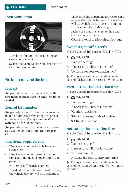
Front ventilation
– Turn knob for continuous opening andclosing of the vents.
– Swivel the vents to alter the direction ofthe vent flow, arrows.
Parked-car ventilation
ConceptThe parked-car ventilation ventilates thecar's interior and lowers its temperature, ifneeded.
General informationThe parked-car ventilation can be switchedon and off directly or by using two presetactivation times. The system remainsswitched on for 30 minutes.
The parked-car ventilation system is oper-ated via the Central Information Display(CID).
Functional requirements– Direct operation: vehicle is in radio-
ready state.
– Direct operation or preset activationtime: does not depend on external tem-perature.
– Battery is sufficiently charged.
If parked-car ventilation is switched on,the vehicle battery will be discharged.
Thus, limit the maximum activation timeto save the vehicle battery. The systemwill be available again after the engineis started or after a short trip.
– Make sure that the vehicle's date andtime are set correctly.
– Open the vents to allow air to flow out.
Switching on/off directlyVia the Central Information Display (CID):
1. "My MINI"
2. "Vehicle settings"
3. If necessary, "Climate functions"
4. "Activate comfort ventilation now"
The symbol on the automatic climatecontrol flashes if the system is switched on.
Preselecting the activation timeVia the Central Information Display (CID):
1. "My MINI"
2. "Vehicle settings"
3. If necessary, "Climate functions"
4. "Comfort ventilation"
5. Select the desired activation time.
6. Set the desired time.
Activating the activation timeVia the Central Information Display (CID):
1. "My MINI"
2. "Vehicle settings"
3. If necessary, "Climate functions"
4. "For start time at:"
Activate the desired activation time.
The symbol on the automatic climatecontrol lights up when the activation time isactivated.
Seite 212
CONTROLS Climate control
212Online Edition for Part no. 01402723778 - VI/18
The symbol on the automatic climatecontrol flashes when the system has beenswitched on.
The system will only be switched on withinthe next 24 hours. After that, it needs to bereactivated.
Seite 213
Climate control CONTROLS
213Online Edition for Part no. 01402723778 - VI/18
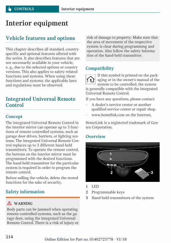
Interior equipment
Vehicle features and options
This chapter describes all standard, country-specific and optional features offered withthe series. It also describes features that arenot necessarily available in your vehicle,e. g., due to the selected options or countryversions. This also applies to safety-relatedfunctions and systems. When using thesefunctions and systems, the applicable lawsand regulations must be observed.
Integrated Universal RemoteControl
ConceptThe integrated Universal Remote Control inthe interior mirror can operate up to 3 func-tions of remote-controlled systems, such asgarage door drives, barriers, or lighting sys-tems. The integrated Universal Remote Con-trol replaces up to 3 different hand-heldtransmitters. To operate the remote control,the buttons on the interior mirror must beprogrammed with the desired functions.The hand-held transmitter for the particularsystem is required in order to program theremote control.
Before selling the vehicle, delete the storedfunctions for the sake of security.
Safety information
WARNING
Body parts can be jammed when operatingremote-controlled systems, such as the ga-rage door, using the integrated UniversalRemote Control. There is a risk of injury or
risk of damage to property. Make sure thatthe area of movement of the respectivesystem is clear during programming andoperation. Also follow the safety informa-tion of the hand-held transmitter.
CompatibilityIf this symbol is printed on the pack-aging or in the owner's manual of thesystem to be controlled, the system
is generally compatible with the integratedUniversal Remote Control.
If you have any questions, please contact:
– A dealer’s service center or anotherqualified service center or repair shop.
– www.homelink.com on the Internet.
HomeLink is a registered trademark of Gen-tex Corporation.
Overview
1 LED
2 Programmable keys
3 Hand-held transmitters of the system
Seite 214
CONTROLS Interior equipment
214Online Edition for Part no. 01402723778 - VI/18
Programming
General information1. Switch on the ignition.
2. Initial setup:
Press and hold the two outer buttons onthe interior mirror simultaneously forapproximately 20 seconds until the LEDon the interior mirror flashes. Thiserases all programming of the buttonson the interior mirror.
3. Hold the hand-held transmitter for thesystem to be controlled approx. 1 to3 inches/2.5 to 8 cm away from the but-tons of the interior mirror. The requireddistance depends on the hand-heldtransmitter.
4. Simultaneously press and hold the but-ton of the desired function on the hand-held transmitter and the button to beprogrammed on the interior mirror. TheLED on the interior mirror will beginflashing slowly.
5. Release both buttons as soon as the LEDflashes more rapidly. The LED flashingfaster indicates that the button on theinterior mirror has been programmed.
If the LED does not flash faster after atleast 60 seconds, change the distancebetween the interior mirror and thehand-held transmitter and repeat thestep. Several more attempts at differentdistances may be necessary. Wait atleast 15 seconds between attempts.
Canada: if programming with the hand-held transmitter was interrupted, holddown the interior mirror button and re-peatedly press and release the hand-heldtransmitter button for 2 seconds.
6. To program other functions on otherbuttons, repeat steps 3 to 5.
The systems can be controlled using the in-terior mirror buttons.
Special feature of the rolling codewireless systemIf you are unable to operate the system af-ter repeated programming, please check ifthe system to be controlled features a roll-ing code radio system.
Read the system's owner's manual, or pressthe programmed button on the interior mir-ror longer. If the LED on the interior mirrorstarts flashing rapidly and then stays litconstantly for 2 seconds, the system fea-tures a rolling code radio system. Flashingand continuous illumination of the LED willrepeat for approximately 20 seconds.
For systems with a rolling code radio sys-tem, the integrated Universal Remote Con-trol and the system also have to besynchronized.
Please read the owner's manual to find outhow to synchronize the system.
Synchronizing is easier with the aid of asecond person.
Synchronizing the universal remote controlwith the system:
1. Park the vehicle within range of the re-mote-controlled system.
2. Program the relevant button on the inte-rior mirror as described.
3. Locate and press the synchronizing but-ton on the system being programmed.You have approx. 30 seconds for thenext step.
4. Hold down the programmed button onthe interior mirror for approximately3 seconds and then release it. If neces-sary, repeat this step up to three timesin order to finish synchronization. Oncesynchronization is complete, the pro-grammed function will be carried out.
Seite 215
Interior equipment CONTROLS
215Online Edition for Part no. 01402723778 - VI/18
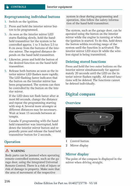
Reprogramming individual buttons1. Switch on the ignition.
2. Press and hold the interior mirror but-ton to be programmed.
3. As soon as the interior mirror LEDstarts flashing slowly, hold the hand-held transmitter for the system to becontrolled approx. 1 to 3 inches/2.5 to8 cm away from the buttons of the inte-rior mirror. The required distance de-pends on the hand-held transmitter.
4. Likewise, press and hold the button ofthe desired function on the hand-heldtransmitter.
5. Release both buttons as soon as the in-terior mirror LED flashes more rapidly.The LED flashing faster indicates thatthe button on the interior mirror hasbeen programmed. The system can thenbe controlled by the button on the inte-rior mirror.
If the LED does not flash faster after atmost 60 seconds, change the distanceand repeat the programming startingwith step 4. Several more attempts atdifferent distances may be necessary.Wait at least 15 seconds between at-tempts.
Canada: if programming with the hand-held transmitter was interrupted, holddown the interior mirror button and re-peatedly press and release the hand-heldtransmitter button for 2 seconds.
Operation
WARNING
Body parts can be jammed when operatingremote-controlled systems, such as the ga-rage door, using the integrated UniversalRemote Control. There is a risk of injury orrisk of damage to property. Make sure thatthe area of movement of the respective
system is clear during programming andoperation. Also follow the safety informa-tion of the hand-held transmitter.
The system, such as the garage door, can beoperated using the button on the interiormirror while the engine is running or whenthe ignition is started. To do this, hold downthe button within receiving range of thesystem until the function is activated. Theinterior mirror LED stays lit while the wire-less signal is being transmitted.
Deleting stored functionsPress and hold the two outer buttons on theinterior mirror simultaneously for approxi-mately 20 seconds until the LED on the in-terior mirror flashes rapidly. All stored func-tions will be deleted. The functions cannotbe deleted individually.
Digital compass
Overview
1 Control button
2 Mirror display
Mirror displayThe point of the compass is displayed in themirror when driving straight.
Seite 216
CONTROLS Interior equipment
216Online Edition for Part no. 01402723778 - VI/18
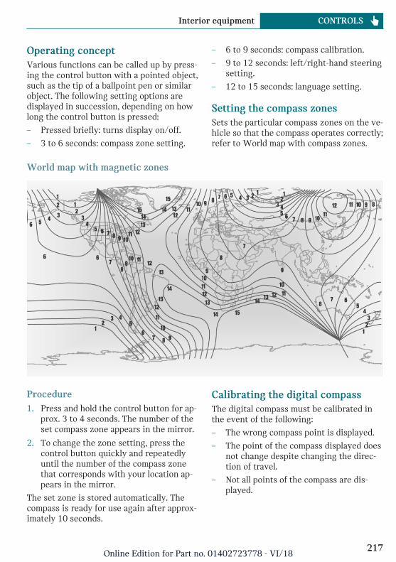
Operating conceptVarious functions can be called up by press-ing the control button with a pointed object,such as the tip of a ballpoint pen or similarobject. The following setting options aredisplayed in succession, depending on howlong the control button is pressed:
– Pressed briefly: turns display on/off.
– 3 to 6 seconds: compass zone setting.
– 6 to 9 seconds: compass calibration.
– 9 to 12 seconds: left/right-hand steeringsetting.
– 12 to 15 seconds: language setting.
Setting the compass zonesSets the particular compass zones on the ve-hicle so that the compass operates correctly;refer to World map with compass zones.
World map with magnetic zones
Procedure1. Press and hold the control button for ap-
prox. 3 to 4 seconds. The number of theset compass zone appears in the mirror.
2. To change the zone setting, press thecontrol button quickly and repeatedlyuntil the number of the compass zonethat corresponds with your location ap-pears in the mirror.
The set zone is stored automatically. Thecompass is ready for use again after approx-imately 10 seconds.
Calibrating the digital compassThe digital compass must be calibrated inthe event of the following:
– The wrong compass point is displayed.
– The point of the compass displayed doesnot change despite changing the direc-tion of travel.
– Not all points of the compass are dis-played.
Seite 217
Interior equipment CONTROLS
217Online Edition for Part no. 01402723778 - VI/18
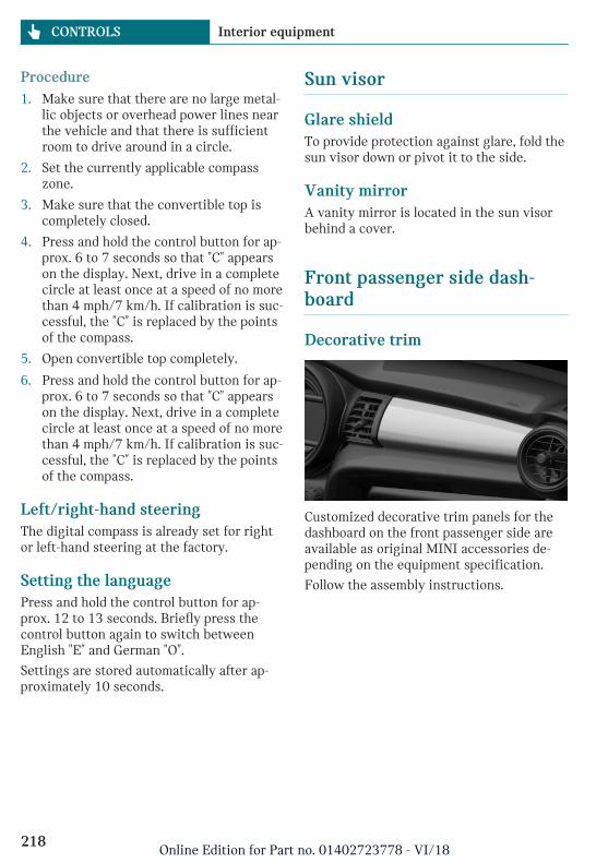
Procedure1. Make sure that there are no large metal-
lic objects or overhead power lines nearthe vehicle and that there is sufficientroom to drive around in a circle.
2. Set the currently applicable compasszone.
3. Make sure that the convertible top iscompletely closed.
4. Press and hold the control button for ap-prox. 6 to 7 seconds so that "C" appearson the display. Next, drive in a completecircle at least once at a speed of no morethan 4 mph/7 km/h. If calibration is suc-cessful, the "C" is replaced by the pointsof the compass.
5. Open convertible top completely.
6. Press and hold the control button for ap-prox. 6 to 7 seconds so that "C" appearson the display. Next, drive in a completecircle at least once at a speed of no morethan 4 mph/7 km/h. If calibration is suc-cessful, the "C" is replaced by the pointsof the compass.
Left/right-hand steeringThe digital compass is already set for rightor left-hand steering at the factory.
Setting the languagePress and hold the control button for ap-prox. 12 to 13 seconds. Briefly press thecontrol button again to switch betweenEnglish "E" and German "O".
Settings are stored automatically after ap-proximately 10 seconds.
Sun visor
Glare shieldTo provide protection against glare, fold thesun visor down or pivot it to the side.
Vanity mirrorA vanity mirror is located in the sun visorbehind a cover.
Front passenger side dash-board
Decorative trim
Customized decorative trim panels for thedashboard on the front passenger side areavailable as original MINI accessories de-pending on the equipment specification.
Follow the assembly instructions.
Seite 218
CONTROLS Interior equipment
218Online Edition for Part no. 01402723778 - VI/18
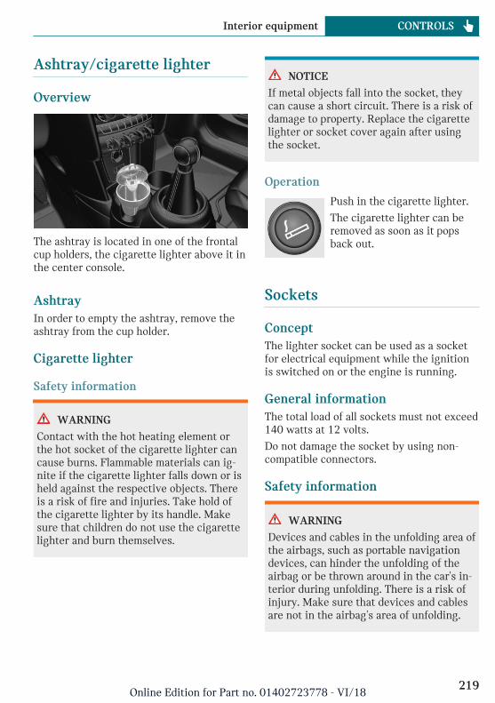
Ashtray/cigarette lighter
Overview
The ashtray is located in one of the frontalcup holders, the cigarette lighter above it inthe center console.
AshtrayIn order to empty the ashtray, remove theashtray from the cup holder.
Cigarette lighter
Safety information
WARNING
Contact with the hot heating element orthe hot socket of the cigarette lighter cancause burns. Flammable materials can ig-nite if the cigarette lighter falls down or isheld against the respective objects. Thereis a risk of fire and injuries. Take hold ofthe cigarette lighter by its handle. Makesure that children do not use the cigarettelighter and burn themselves.
NOTICE
If metal objects fall into the socket, theycan cause a short circuit. There is a risk ofdamage to property. Replace the cigarettelighter or socket cover again after usingthe socket.
Operation
Push in the cigarette lighter.
The cigarette lighter can beremoved as soon as it popsback out.
Sockets
ConceptThe lighter socket can be used as a socketfor electrical equipment while the ignitionis switched on or the engine is running.
General informationThe total load of all sockets must not exceed140 watts at 12 volts.
Do not damage the socket by using non-compatible connectors.
Safety information
WARNING
Devices and cables in the unfolding area ofthe airbags, such as portable navigationdevices, can hinder the unfolding of theairbag or be thrown around in the car's in-terior during unfolding. There is a risk ofinjury. Make sure that devices and cablesare not in the airbag's area of unfolding.
Seite 219
Interior equipment CONTROLS
219Online Edition for Part no. 01402723778 - VI/18
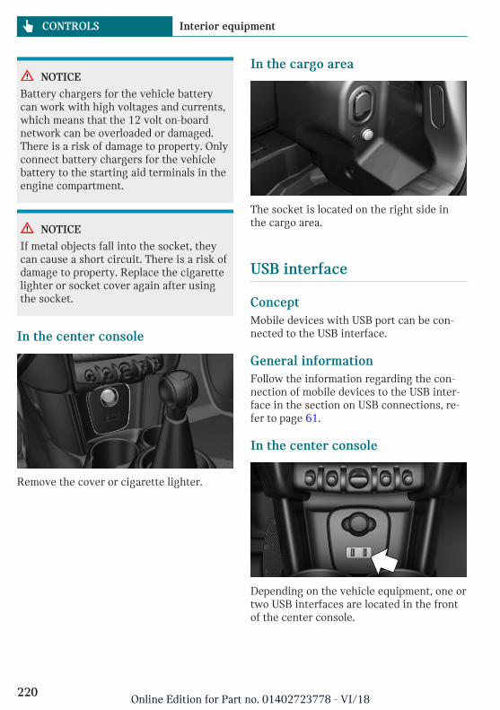
NOTICE
Battery chargers for the vehicle batterycan work with high voltages and currents,which means that the 12 volt on-boardnetwork can be overloaded or damaged.There is a risk of damage to property. Onlyconnect battery chargers for the vehiclebattery to the starting aid terminals in theengine compartment.
NOTICE
If metal objects fall into the socket, theycan cause a short circuit. There is a risk ofdamage to property. Replace the cigarettelighter or socket cover again after usingthe socket.
In the center console
Remove the cover or cigarette lighter.
In the cargo area
The socket is located on the right side inthe cargo area.
USB interface
ConceptMobile devices with USB port can be con-nected to the USB interface.
General informationFollow the information regarding the con-nection of mobile devices to the USB inter-face in the section on USB connections, re-fer to page 61.
In the center console
Depending on the vehicle equipment, one ortwo USB interfaces are located in the frontof the center console.
Seite 220
CONTROLS Interior equipment
220Online Edition for Part no. 01402723778 - VI/18
Storage compartments
Vehicle features and options
This chapter describes all standard, country-specific and optional features offered withthe series. It also describes features that arenot necessarily available in your vehicle,e. g., due to the selected options or countryversions. This also applies to safety-relatedfunctions and systems. When using thesefunctions and systems, the applicable lawsand regulations must be observed.
Safety information
WARNING
Loose objects or devices with a cable con-nection to the vehicle, for instance mobilephones, can be thrown into the car's inte-rior while driving, for instance in theevent of an accident or during braking andevasive maneuvers. There is a risk of in-jury. Secure loose objects or devices witha cable connection to the vehicle in thecar's interior.
NOTICE
Anti-slip pads such as anti-slip mats candamage the dashboard. There is a risk ofdamage to property. Do not use anti-slippads.
Overview
The following storage compartments areavailable in the car's interior:
– Glove compartment on the front passen-ger side.
– Compartments in the doors.
– Storage compartment in the center arm-rest.
– Storage compartment in front of the cupholders.
– Storage compartments in the cargo area.
– Storage tray in the center console.
– Pockets on the backrests of the frontseats.
Glove compartment
Safety information
WARNING
Folded open, the glove compartment pro-trudes in the car's interior. Objects in theglove compartment can be thrown into thecar's interior while driving, for instance inthe event of an accident or during brakingand evasive maneuvers. There is a risk ofinjury. Always close the glove compart-ment immediately after using it.
Seite 221
Storage compartments CONTROLS
221Online Edition for Part no. 01402723778 - VI/18
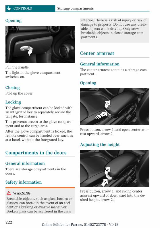
Opening
Pull the handle.
The light in the glove compartmentswitches on.
ClosingFold up the cover.
LockingThe glove compartment can be locked withan integrated key to separately secure thetailgate, for instance.
This prevents access to the glove compart-ment and to the cargo area.
After the glove compartment is locked, theremote control can be handed over, such asat a hotel, without the integrated key.
Compartments in the doors
General informationThere are storage compartments in thedoors.
Safety information
WARNING
Breakable objects, such as glass bottles orglasses, can break in the event of an acci-dent or a braking or evasive maneuver.Broken glass can be scattered in the car's
interior. There is a risk of injury or risk ofdamage to property. Do not use any break-able objects while driving. Only stowbreakable objects in closed storage com-partments.
Center armrest
General informationThe center armrest contains a storage com-partment.
Opening
Press button, arrow 1, and open center arm-rest upward, arrow 2.
Adjusting the height
Press button, arrow 1, and swing centerarmrest upward or downward into the de-sired height, arrow 2.
Seite 222
CONTROLS Storage compartments
222Online Edition for Part no. 01402723778 - VI/18
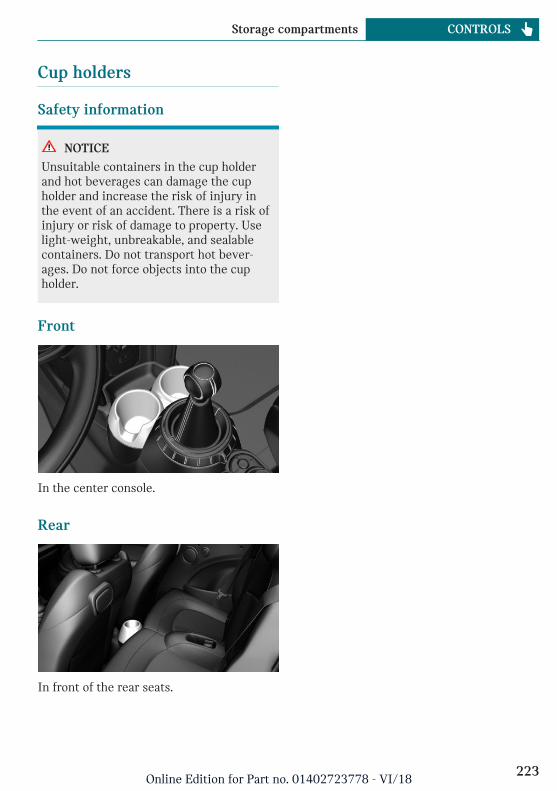
Cup holders
Safety information
NOTICE
Unsuitable containers in the cup holderand hot beverages can damage the cupholder and increase the risk of injury inthe event of an accident. There is a risk ofinjury or risk of damage to property. Uselight-weight, unbreakable, and sealablecontainers. Do not transport hot bever-ages. Do not force objects into the cupholder.
Front
In the center console.
Rear
In front of the rear seats.
Seite 223
Storage compartments CONTROLS
223Online Edition for Part no. 01402723778 - VI/18
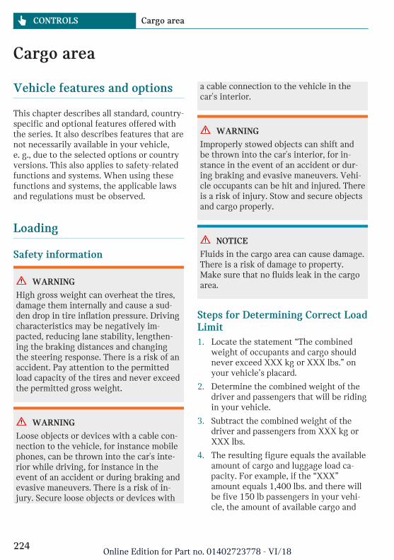
Cargo area
Vehicle features and options
This chapter describes all standard, country-specific and optional features offered withthe series. It also describes features that arenot necessarily available in your vehicle,e. g., due to the selected options or countryversions. This also applies to safety-relatedfunctions and systems. When using thesefunctions and systems, the applicable lawsand regulations must be observed.
Loading
Safety information
WARNING
High gross weight can overheat the tires,damage them internally and cause a sud-den drop in tire inflation pressure. Drivingcharacteristics may be negatively im-pacted, reducing lane stability, lengthen-ing the braking distances and changingthe steering response. There is a risk of anaccident. Pay attention to the permittedload capacity of the tires and never exceedthe permitted gross weight.
WARNING
Loose objects or devices with a cable con-nection to the vehicle, for instance mobilephones, can be thrown into the car's inte-rior while driving, for instance in theevent of an accident or during braking andevasive maneuvers. There is a risk of in-jury. Secure loose objects or devices with
a cable connection to the vehicle in thecar's interior.
WARNING
Improperly stowed objects can shift andbe thrown into the car's interior, for in-stance in the event of an accident or dur-ing braking and evasive maneuvers. Vehi-cle occupants can be hit and injured. Thereis a risk of injury. Stow and secure objectsand cargo properly.
NOTICE
Fluids in the cargo area can cause damage.There is a risk of damage to property.Make sure that no fluids leak in the cargoarea.
Steps for Determining Correct LoadLimit1. Locate the statement “The combined
weight of occupants and cargo shouldnever exceed XXX kg or XXX lbs.” onyour vehicle’s placard.
2. Determine the combined weight of thedriver and passengers that will be ridingin your vehicle.
3. Subtract the combined weight of thedriver and passengers from XXX kg orXXX lbs.
4. The resulting figure equals the availableamount of cargo and luggage load ca-pacity. For example, if the “XXX”amount equals 1,400 lbs. and there willbe five 150 lb passengers in your vehi-cle, the amount of available cargo and
Seite 224
CONTROLS Cargo area
224Online Edition for Part no. 01402723778 - VI/18
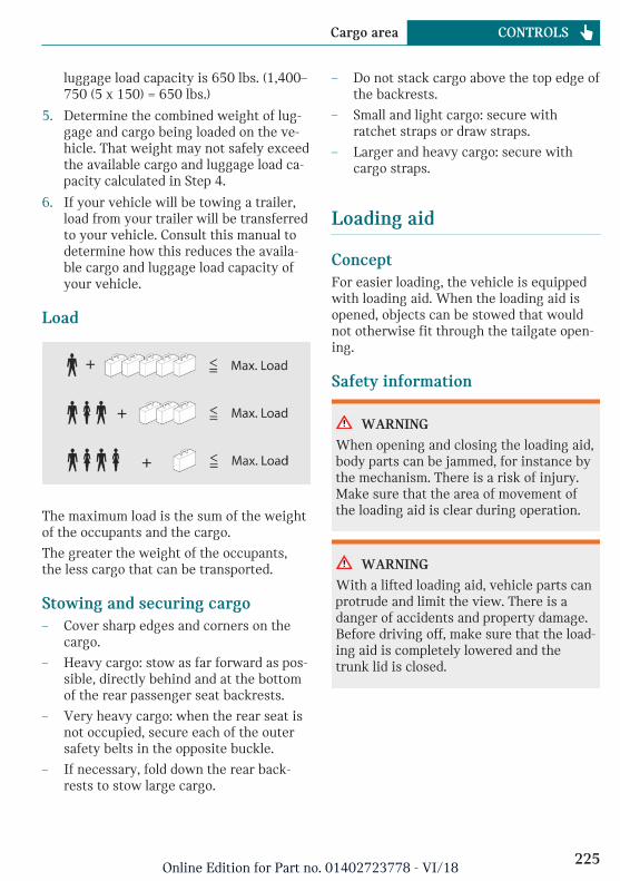
luggage load capacity is 650 lbs. (1,400–750 (5 x 150) = 650 lbs.)
5. Determine the combined weight of lug-gage and cargo being loaded on the ve-hicle. That weight may not safely exceedthe available cargo and luggage load ca-pacity calculated in Step 4.
6. If your vehicle will be towing a trailer,load from your trailer will be transferredto your vehicle. Consult this manual todetermine how this reduces the availa-ble cargo and luggage load capacity ofyour vehicle.
Load
The maximum load is the sum of the weightof the occupants and the cargo.
The greater the weight of the occupants,the less cargo that can be transported.
Stowing and securing cargo– Cover sharp edges and corners on the
cargo.
– Heavy cargo: stow as far forward as pos-sible, directly behind and at the bottomof the rear passenger seat backrests.
– Very heavy cargo: when the rear seat isnot occupied, secure each of the outersafety belts in the opposite buckle.
– If necessary, fold down the rear back-rests to stow large cargo.
– Do not stack cargo above the top edge ofthe backrests.
– Small and light cargo: secure withratchet straps or draw straps.
– Larger and heavy cargo: secure withcargo straps.
Loading aid
ConceptFor easier loading, the vehicle is equippedwith loading aid. When the loading aid isopened, objects can be stowed that wouldnot otherwise fit through the tailgate open-ing.
Safety information
WARNING
When opening and closing the loading aid,body parts can be jammed, for instance bythe mechanism. There is a risk of injury.Make sure that the area of movement ofthe loading aid is clear during operation.
WARNING
With a lifted loading aid, vehicle parts canprotrude and limit the view. There is adanger of accidents and property damage.Before driving off, make sure that the load-ing aid is completely lowered and thetrunk lid is closed.
Seite 225
Cargo area CONTROLS
225Online Edition for Part no. 01402723778 - VI/18
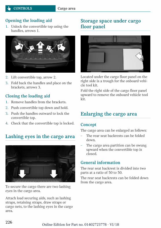
Opening the loading aid1. Unlock the convertible top using the
handles, arrows 1.
2. Lift convertible top, arrow 2.
3. Fold back the handles and place on thebrackets, arrows 3.
Closing the loading aid1. Remove handles from the brackets.
2. Push convertible top down and hold.
3. Push the handles outward to lock theconvertible top.
4. Check that the convertible top is locked.
Lashing eyes in the cargo area
To secure the cargo there are two lashingeyes in the cargo area.
Attach load securing aids, such as lashingstraps, retaining straps, draw straps orcargo nets, to the lashing eyes in the cargoarea.
Storage space under cargofloor panel
Located under the cargo floor panel on theright side is a trough for the onboard vehi-cle tool kit.
Fold the right side of the cargo floor panelupward to remove the onboard vehicle toolkit.
Enlarging the cargo area
ConceptThe cargo area can be enlarged as follows:
– The rear seat backrests can be foldeddown.
– The cargo area partition can be swungupward when the convertible top isclosed.
General informationThe rear seat backrest is divided into twoparts at a ratio of 50 to 50.
The rear seat backrests can be folded downfrom the cargo area.
Seite 226
CONTROLS Cargo area
226Online Edition for Part no. 01402723778 - VI/18
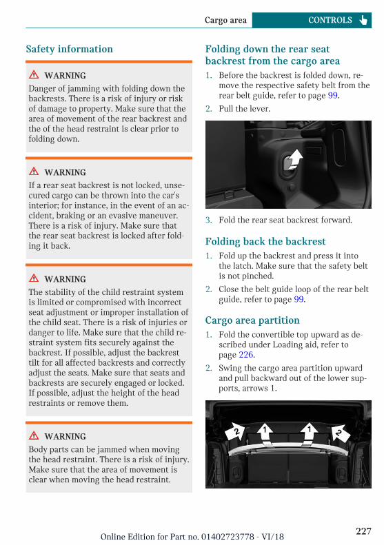
Safety information
WARNING
Danger of jamming with folding down thebackrests. There is a risk of injury or riskof damage to property. Make sure that thearea of movement of the rear backrest andthe of the head restraint is clear prior tofolding down.
WARNING
If a rear seat backrest is not locked, unse-cured cargo can be thrown into the car'sinterior; for instance, in the event of an ac-cident, braking or an evasive maneuver.There is a risk of injury. Make sure thatthe rear seat backrest is locked after fold-ing it back.
WARNING
The stability of the child restraint systemis limited or compromised with incorrectseat adjustment or improper installation ofthe child seat. There is a risk of injuries ordanger to life. Make sure that the child re-straint system fits securely against thebackrest. If possible, adjust the backresttilt for all affected backrests and correctlyadjust the seats. Make sure that seats andbackrests are securely engaged or locked.If possible, adjust the height of the headrestraints or remove them.
WARNING
Body parts can be jammed when movingthe head restraint. There is a risk of injury.Make sure that the area of movement isclear when moving the head restraint.
Folding down the rear seatbackrest from the cargo area1. Before the backrest is folded down, re-
move the respective safety belt from therear belt guide, refer to page 99.
2. Pull the lever.
3. Fold the rear seat backrest forward.
Folding back the backrest1. Fold up the backrest and press it into
the latch. Make sure that the safety beltis not pinched.
2. Close the belt guide loop of the rear beltguide, refer to page 99.
Cargo area partition1. Fold the convertible top upward as de-
scribed under Loading aid, refer topage 226.
2. Swing the cargo area partition upwardand pull backward out of the lower sup-ports, arrows 1.
Seite 227
Cargo area CONTROLS
227Online Edition for Part no. 01402723778 - VI/18
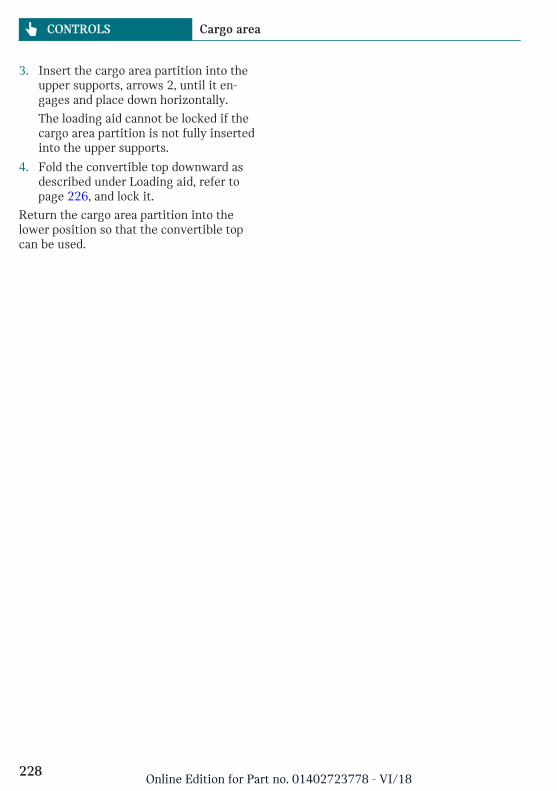
3. Insert the cargo area partition into theupper supports, arrows 2, until it en-gages and place down horizontally.
The loading aid cannot be locked if thecargo area partition is not fully insertedinto the upper supports.
4. Fold the convertible top downward asdescribed under Loading aid, refer topage 226, and lock it.
Return the cargo area partition into thelower position so that the convertible topcan be used.
Seite 228
CONTROLS Cargo area
228Online Edition for Part no. 01402723778 - VI/18

Seite 229
Cargo area CONTROLS
229Online Edition for Part no. 01402723778 - VI/18

230
Online Edition for Part no. 01402723778 - VI/18
DRIVING TIPS
Things to remember when driving .................................................. 232Saving fuel ............................................................................................... 237
231Online Edition for Part no. 01402723778 - VI/18
Things to remember when driving
Vehicle features and options
This chapter describes all standard, country-specific and optional features offered withthe series. It also describes features that arenot necessarily available in your vehicle,e. g., due to the selected options or countryversions. This also applies to safety-relatedfunctions and systems. When using thesefunctions and systems, the applicable lawsand regulations must be observed.
Breaking-in period
General informationMoving parts need to begin working to-gether smoothly.
The following instructions will help you toachieve a long vehicle life and good effi-ciency.
During break-in, do not use the LaunchControl, refer to page 131.
Safety information
WARNING
Due to new parts and components, safetyand driver assistance systems can reactwith a delay. There is a risk of an accident.After installing new parts or with a newvehicle, drive conservatively and inter-vene early if necessary. Observe the break-in procedures of the respective parts andcomponents.
Engine, transmission, and axledrive
Up to 1,200 miles/2,000 kmDo not exceed the maximum engine androad speed:
– For gasoline engine 4,500 rpm and100 mph/160 km/h.
Avoid full load or kickdown under all cir-cumstances.
From 1,200 miles/2,000 kmThe engine and vehicle speed can graduallybe increased.
TiresTire traction is not optimal due to manufac-turing circumstances when tires are brand-new; they achieve their full traction poten-tial after a break-in time.
Drive conservatively for the first200 miles/300 km.
Brake systemBrake discs and brake pads only reach theirfull effectiveness after ap-prox. 300 miles/500 km. Drive moderatelyduring this break-in period.
ClutchThe function of the clutch reaches its opti-mal level only after a distance driven of ap-prox. 300 miles/500 km. During this break-in period, engage the clutch gently.
Following part replacementThe same break-in procedures should be ob-served if any of the components above-men-
Seite 232
DRIVING TIPS Things to remember when driving
232Online Edition for Part no. 01402723778 - VI/18
tioned have to be renewed in the course ofthe vehicle's operating life.
General driving notes
Closing the tailgate
Safety information
WARNING
An open trunk lid protrudes from the vehi-cle and can endanger occupants and othertraffic participants or damage the vehiclein the event of an accident, braking or eva-sive maneuvers. In addition, exhaustfumes may enter the car's interior. Thereis a risk of injury or risk of damage toproperty. Do not drive with the trunk lidopen.
Driving with the tailgate openIf driving with the tailgate open cannot beavoided:
– If the convertible top is closed, close allwindows and the sliding sun roof.
– Greatly increase the air flow from thevents.
– Drive moderately.
Hot exhaust gas system
WARNING
During driving operation, high tempera-tures can occur underneath the vehiclebody, for instance caused by the exhaustgas system. If combustible materials, suchas leaves or grass, come in contact withhot parts of the exhaust gas system, thesematerials can ignite. There is a risk of in-jury or risk of damage to property. Do notremove the heat shields installed and
never apply undercoating to them. Makesure that no combustible materials cancome in contact with hot vehicle parts indriving operation, idle or during parking.Do not touch the hot exhaust gas system.
Mobile communication devices inthe vehicle
WARNING
Vehicle electronics and mobile phones caninfluence one another. There is radiationdue to the transmission operations of mo-bile phones. There is a risk of injury orrisk of damage to property. If possible, inthe car's interior use only mobile phoneswith direct connections to an exterior an-tenna in order to exclude mutual interfer-ence and deflect the radiation from thecar's interior.
HydroplaningOn wet or slushy roads, a wedge of watercan form between the tires and road sur-face.
This phenomenon is referred to as hydro-planing. It is characterized by a partial orcomplete loss of contact between the tiresand the road surface, ultimately undermin-ing your ability to steer and brake the vehi-cle.
Driving through water
General informationWhen driving through water, follow the fol-lowing:
– Drive through calm water only.
– Drive through water only if it is notdeeper than maximum 9.8 inches/25 cm.
Seite 233
Things to remember when driving DRIVING TIPS
233Online Edition for Part no. 01402723778 - VI/18
– Drive through water no faster thanwalking speed, up to 3 mph/5 km/h.
Safety information
NOTICE
When driving too quickly through toodeep water, water can enter into the en-gine compartment, the electrical system orthe transmission. There is a risk of damageto property. When driving through water,do not exceed the maximum indicated wa-ter level and the maximum speed for driv-ing through water.
Braking safely
General informationThe vehicle is equipped with ABS as astandard feature.
Perform an emergency stop in situationsthat require such.
Steering is still responsive. You can stillavoid any obstacles with a minimum ofsteering effort.
Pulsation of the brake pedal and soundsfrom the hydraulic circuits indicate thatABS is in its active mode.
Objects in the area around the pedals
WARNING
Objects in the driver's floor area can limitthe pedal distance or block a depressedpedal. There is a risk of an accident. Stowobjects in the vehicle such that they aresecured and cannot enter into the driver'sfloor area. Use floor mats that are suitablefor the vehicle and can be safely attachedto the floor. Do not use loose floor matsand do not layer several floor mats. Makesure that there is sufficient clearance for
the pedals. Ensure that the floor mats aresecurely fastened again after they were re-moved, for instance for cleaning.
Driving in wet conditionsWhen roads are wet, salted, or in heavyrain, gently press the brake pedal every fewmiles.
Ensure that this action does not endangerother traffic.
The heat generated during braking driesbrake discs and brake pads and protectsthem against corrosion.
In this way braking efficiency will be avail-able when you need it.
Hills
General information
Drive long or steep downhill gradients inthe gear that requires least braking effort.Otherwise, the brakes may overheat and re-duce brake efficiency.
You can increase the engine's braking effectby shifting down, going all the way to firstgear, if needed.
Safety information
WARNING
Light but consistent brake pressure canlead to high temperatures, brakes wearingout and possibly even brake failure. Thereis a risk of an accident. Avoid placing ex-cessive stress on the brake system.
WARNING
In idle state or with the engine switchedoff, safety-relevant functions, for instanceengine braking effect, braking force boostand steering assistance, are restricted or
Seite 234
DRIVING TIPS Things to remember when driving
234Online Edition for Part no. 01402723778 - VI/18
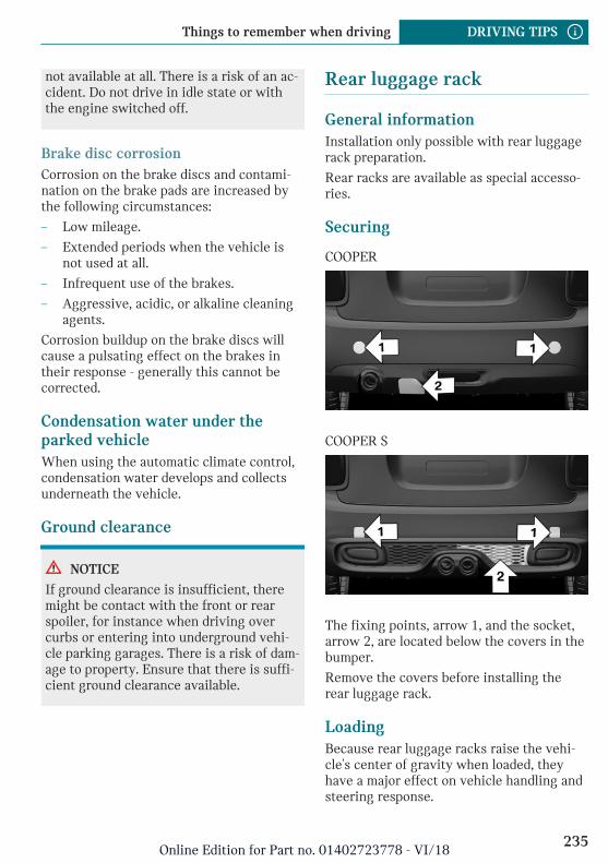
not available at all. There is a risk of an ac-cident. Do not drive in idle state or withthe engine switched off.
Brake disc corrosionCorrosion on the brake discs and contami-nation on the brake pads are increased bythe following circumstances:
– Low mileage.
– Extended periods when the vehicle isnot used at all.
– Infrequent use of the brakes.
– Aggressive, acidic, or alkaline cleaningagents.
Corrosion buildup on the brake discs willcause a pulsating effect on the brakes intheir response - generally this cannot becorrected.
Condensation water under theparked vehicleWhen using the automatic climate control,condensation water develops and collectsunderneath the vehicle.
Ground clearance
NOTICE
If ground clearance is insufficient, theremight be contact with the front or rearspoiler, for instance when driving overcurbs or entering into underground vehi-cle parking garages. There is a risk of dam-age to property. Ensure that there is suffi-cient ground clearance available.
Rear luggage rack
General informationInstallation only possible with rear luggagerack preparation.
Rear racks are available as special accesso-ries.
Securing
COOPER
COOPER S
The fixing points, arrow 1, and the socket,arrow 2, are located below the covers in thebumper.
Remove the covers before installing therear luggage rack.
LoadingBecause rear luggage racks raise the vehi-cle's center of gravity when loaded, theyhave a major effect on vehicle handling andsteering response.
Seite 235
Things to remember when driving DRIVING TIPS
235Online Edition for Part no. 01402723778 - VI/18
Therefore, note the following when loadingand driving:
– Do not exceed the approved axle loadand the approved gross vehicle weight.
– Drive smoothly. Avoid sudden accelera-tion and braking maneuvers. Take cor-ners gently.
Power consumptionBefore starting to drive, check the functionof the rear luggage rack lights.
The rear luggage rack lights must not con-sume more than:
– Turn signals: 42 watts per side.
– Rear lights: 50 watts per side.
– Brake lights: 84 watts in total.
– Rear fog lights: 42 watts in total.
– Backup light: 42 watts in total.
Driving on racetracks
Higher mechanical and thermal loads duringracetrack operation lead to increased wear.This wear is not covered by the warranty.The vehicle is not designed for use in motorsports competition.
Seite 236
DRIVING TIPS Things to remember when driving
236Online Edition for Part no. 01402723778 - VI/18
Saving fuel
Vehicle features and options
This chapter describes all standard, country-specific and optional features offered withthe series. It also describes features that arenot necessarily available in your vehicle,e. g., due to the selected options or countryversions. This also applies to safety-relatedfunctions and systems. When using thesefunctions and systems, the applicable lawsand regulations must be observed.
General information
The vehicle contains advanced technologiesfor the reduction of fuel consumption andemission values.
Fuel consumption depends on a number ofdifferent factors.
The implementation of certain measures,driving style and regular maintenance caninfluence fuel consumption and environ-mental impact.
Remove unnecessary cargo
Additional weight increases fuel consump-tion.
Remove attached parts follow-ing use
Remove rear luggage racks which are nolonger required following use.
Attached parts on the vehicle impair theaerodynamics and increase the fuel con-sumption.
Closing the windows
Open windows increase air resistance andtherefore lead to greater fuel consumption.
Tires
General informationTires can affect fuel consumption in variousways, for instance tire size may influencefuel consumption.
Check the tire inflation pressureregularlyCheck and, if needed, correct the tire infla-tion pressure at least twice a month and be-fore starting on a long trip.
Low tire inflation pressure increases rollingresistance and thus raises fuel consumptionand tire wear.
Drive away without delay
Do not wait for the engine to warm-upwhile the vehicle remains stationary. Startdriving right away, but at moderate enginespeeds.
This is the fastest way for the cold engineto reach its operating temperature.
Seite 237
Saving fuel DRIVING TIPS
237Online Edition for Part no. 01402723778 - VI/18
Look well ahead when driving
Driving smoothly and proactively reducesfuel consumption.
Avoid unnecessary acceleration and brak-ing.
By maintaining a suitable distance to thevehicle driving ahead of you.
Avoid high engine speeds
Driving at low engine speeds lowers fuelconsumption and reduces wear.
If necessary, observe the vehicle's gear shiftindicator, refer to page 140.
Use coasting conditions
When approaching a red light, take yourfoot off the accelerator and let the vehiclecoast to a halt.
For going downhill take your foot off the ac-celerator and let the vehicle roll.
The flow of fuel is interrupted while coast-ing.
Switch off the engine duringlonger stops
Switching off the engineSwitch off the engine during longer stops,for instance at traffic lights, railroad cross-ings or in traffic congestion.
Auto Start/Stop functionThe Auto Start/Stop function of the vehicleautomatically switches off the engine dur-ing a stop.
If the engine is switched off and then re-started rather than leaving the engine run-ning constantly, fuel consumption and emis-sions are reduced. Savings can begin withina few seconds of switching off the engine.
In addition, fuel consumption is also deter-mined by other factors, such as drivingstyle, road conditions, maintenance or envi-ronmental factors.
Switch off any functions thatare not currently needed
Functions such as seat heating and the rearwindow defroster require a lot of energyand consume additional fuel, especially incity and stop-and-go traffic.
Switch off these functions if they are notneeded.
Have maintenance carried out
Have the vehicle maintained regularly toachieve optimal vehicle efficiency and serv-ice life. MINI recommends that mainte-nance work be performed by a MINI servicecenter.
Also note the MINI maintenance systems,refer to page 280.
GREEN Mode
ConceptGREEN Mode supports a driving style thatsaves on fuel consumption. For this pur-pose, the engine control and comfort fea-tures, for instance the climate control out-put, are adjusted.
For Steptronic transmission:
Seite 238
DRIVING TIPS Saving fuel
238Online Edition for Part no. 01402723778 - VI/18
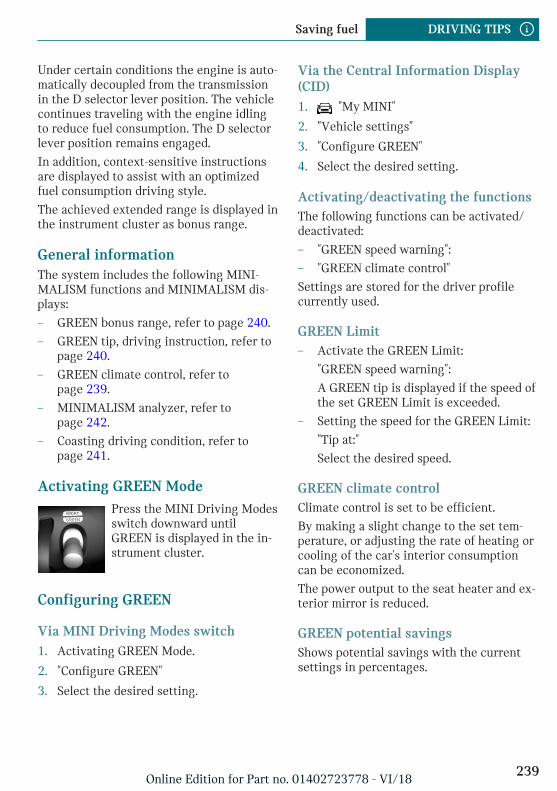
Under certain conditions the engine is auto-matically decoupled from the transmissionin the D selector lever position. The vehiclecontinues traveling with the engine idlingto reduce fuel consumption. The D selectorlever position remains engaged.
In addition, context-sensitive instructionsare displayed to assist with an optimizedfuel consumption driving style.
The achieved extended range is displayed inthe instrument cluster as bonus range.
General informationThe system includes the following MINI-MALISM functions and MINIMALISM dis-plays:
– GREEN bonus range, refer to page 240.
– GREEN tip, driving instruction, refer topage 240.
– GREEN climate control, refer topage 239.
– MINIMALISM analyzer, refer topage 242.
– Coasting driving condition, refer topage 241.
Activating GREEN ModePress the MINI Driving Modesswitch downward untilGREEN is displayed in the in-strument cluster.
Configuring GREEN
Via MINI Driving Modes switch1. Activating GREEN Mode.
2. "Configure GREEN"
3. Select the desired setting.
Via the Central Information Display(CID)1. "My MINI"
2. "Vehicle settings"
3. "Configure GREEN"
4. Select the desired setting.
Activating/deactivating the functionsThe following functions can be activated/deactivated:
– "GREEN speed warning":
– "GREEN climate control"
Settings are stored for the driver profilecurrently used.
GREEN Limit– Activate the GREEN Limit:
"GREEN speed warning":
A GREEN tip is displayed if the speed ofthe set GREEN Limit is exceeded.
– Setting the speed for the GREEN Limit:
"Tip at:"
Select the desired speed.
GREEN climate controlClimate control is set to be efficient.
By making a slight change to the set tem-perature, or adjusting the rate of heating orcooling of the car's interior consumptioncan be economized.
The power output to the seat heater and ex-terior mirror is reduced.
GREEN potential savingsShows potential savings with the currentsettings in percentages.
Seite 239
Saving fuel DRIVING TIPS
239Online Edition for Part no. 01402723778 - VI/18
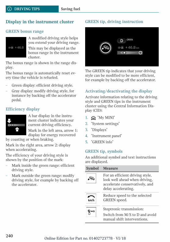
Display in the instrument cluster
GREEN bonus range
A modified driving style helpsyou extend your driving range.
This may be displayed as thebonus range in the instrumentcluster.
The bonus range is shown in the range dis-play.
The bonus range is automatically reset ev-ery time the vehicle is refueled.
– Green display: efficient driving style.
– Gray display: modify driving style, forinstance by backing off the acceleratorpedal.
Efficiency display
A bar display in the instru-ment cluster indicates yourcurrent driving efficiency.
Mark in the left area, arrow 1:display for energy recovered
by coasting or when braking.
Mark in the right area, arrow 2: displaywhen accelerating.
The efficiency of your driving style isshown by the position of the mark:
– Mark inside the green range: efficientdriving style.
– Mark outside the green range: modifydriving style, for example by backing offthe accelerator.
GREEN tip, driving instruction
The GREEN tip indicates that your drivingstyle can be modified to be more efficient,for example by backing off the accelerator.
Activating/deactivating the displayActivate information relating to the drivingstyle and GREEN tips in the instrumentcluster using the Central Information Dis-play (CID):
1. "My MINI"
2. "System settings"
3. "Displays"
4. "Instrument panel"
5. "GREEN info"
GREEN tip, symbolsAn additional symbol and text instructionsare displayed.
Symbol Measure
For an efficient driving style,look well ahead when driving,accelerate conservatively, anddelay accelerating.
Reduce speed to the selectedGREEN speed.
Steptronic transmission:
Switch from M/S to D and avoidmanual shift interventions.
Seite 240
DRIVING TIPS Saving fuel
240Online Edition for Part no. 01402723778 - VI/18
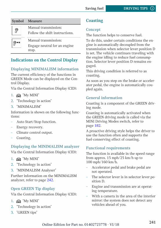
Symbol Measure
Manual transmission:
Follow the shift instructions.
Manual transmission:
Engage neutral for an enginestop.
Indications on the Control Display
Displaying MINIMALISM informationThe current efficiency of the functions inGREEN Mode can be displayed on the Con-trol Display.
Via the Central Information Display (CID):
1. "My MINI"
2. "Technology in action"
3. "MINIMALISM"
Information is shown on the following func-tions:
– Auto Start/Stop function.
– Energy recovery.
– Climate control output.
– Coasting.
Displaying the MINIMALISM analyzerVia the Central Information Display (CID):
1. "My MINI"
2. "Technology in action"
3. "MINIMALISM Analyser"
Further information on the MINIMALISManalyzer, refer to page 242.
Open GREEN Tip displayVia the Central Information Display (CID):
1. "My MINI"
2. "Technology in action"
3. "GREEN tips"
Coasting
ConceptThe function helps to conserve fuel.
To do this, under certain conditions the en-gine is automatically decoupled from thetransmission when selector lever position Dis set. The vehicle continues traveling withthe engine idling to reduce fuel consump-tion. Selector lever position D remains en-gaged.
This driving condition is referred to ascoasting.
As soon as you step on the brake or acceler-ator pedal, the engine is automatically cou-pled again.
General informationCoasting is a component of the GREEN driv-ing mode.
Coasting is automatically activated whenthe GREEN driving mode is called via theMINI Driving Modes switch, refer topage 182.
A proactive driving style helps the driver touse the function often and supports thefuel-conserving effect of coasting.
Functional requirementsThe function is available in the speed rangefrom approx. 15 mph/25 km/h up to100 mph/160 km/h.
– Accelerator pedal and brake pedal arenot operated.
– The selector lever is in selector lever po-sition D.
– Engine and transmission are at operat-ing temperature.
– With a camera in the area of the interiormirror: the system does not detect anyvehicles ahead of you.
Seite 241
Saving fuel DRIVING TIPS
241Online Edition for Part no. 01402723778 - VI/18
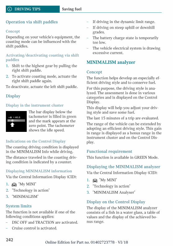
Operation via shift paddles
Concept
Depending on your vehicle's equipment, thecoasting mode can be influenced with theshift paddles.
Activating/deactivating coasting via shiftpaddles
1. Shift to the highest gear by pulling theright shift paddle.
2. To activate coasting mode, actuate theright shift paddle again.
To deactivate, actuate the left shift paddle.
Display
Display in the instrument cluster
The bar display below thetachometer is filled in greenand the mark appears at thezero point. The tachometershows the idle speed.
Indications on the Control Display
The coasting driving condition is displayedin the MINIMALISM Info while driving.
The distance traveled in the coasting driv-ing condition is indicated by a counter.
Displaying MINIMALISM information
Via the Central Information Display (CID):
1. "My MINI"
2. "Technology in action"
3. "MINIMALISM"
System limitsThe function is not available if one of thefollowing conditions applies:
– DSC OFF and TRACTION are activated.
– Cruise control is activated.
– If driving in the dynamic limit range.
– If driving on steep uphill or downhillgrades.
– The battery charge state is temporarilytoo low.
– The vehicle electrical system is drawingexcessive current.
MINIMALISM analyzer
ConceptThe function helps develop an especially ef-ficient driving style and to conserve fuel.
For this purpose, the driving style is ana-lyzed. The assessment is done in variouscategories and is displayed on the ControlDisplay.
This display will help you adjust your driv-ing style and save some fuel.
The last 15 minutes of a trip are evaluated.
The range of the vehicle can be extended byadopting an efficient driving style. This gainin range is displayed as a bonus range in theinstrument cluster and on the Control Dis-play.
Functional requirementThis function is available in GREEN Mode.
Displaying the MINIMALISM analyzerVia the Central Information Display (CID):
1. "My MINI"
2. "Technology in action"
3. "MINIMALISM Analyser"
Display on the Control DisplayThe display of the MINIMALISM analyzerconsists of a fish in a water glass, a table ofvalues and the display of the achieved bo-nus range.
Seite 242
DRIVING TIPS Saving fuel
242Online Edition for Part no. 01402723778 - VI/18
The fish and the movements of the water inthe bowl symbolize the efficiency of thedriving style.
The more efficient the driving style, the lessthe water sloshes around in the bowl andthe better is the fish's mood. If the drivingstyle is inefficient, the water oscillates, thefish's mood worsens, and a reduced numberof stars is displayed.
The table of values contains stars and evalu-ates the driving style in different catego-ries. The more efficient the driving style,the more stars are displayed in the table.
The bonus range achieved by a driving stylethat minimizes fuel consumption is dis-played below the table of values. The moreefficient the driving style, the faster the bo-nus range increases.
To assist with an efficient driving style,GREEN tips are displayed while driving.
Tips for an energy-saving driving style, Sav-ing fuel, refer to page 237.
Seite 243
Saving fuel DRIVING TIPS
243Online Edition for Part no. 01402723778 - VI/18

244
Online Edition for Part no. 01402723778 - VI/18
MOBILITY
Refueling .................................................................................................. 246Fuel ............................................................................................................ 248Wheels and tires .................................................................................... 250Engine compartment ............................................................................ 271Engine oil ................................................................................................. 274Coolant ...................................................................................................... 278Maintenance ........................................................................................... 280Replacing components ......................................................................... 282Breakdown assistance .......................................................................... 293Care ............................................................................................................ 301
245Online Edition for Part no. 01402723778 - VI/18
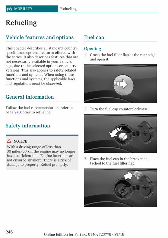
Refueling
Vehicle features and options
This chapter describes all standard, country-specific and optional features offered withthe series. It also describes features that arenot necessarily available in your vehicle,e. g., due to the selected options or countryversions. This also applies to safety-relatedfunctions and systems. When using thesefunctions and systems, the applicable lawsand regulations must be observed.
General information
Follow the fuel recommendation, refer topage 248, prior to refueling.
Safety information
NOTICE
With a driving range of less than30 miles/50 km the engine may no longerhave sufficient fuel. Engine functions arenot ensured anymore. There is a risk ofdamage to property. Refuel promptly.
Fuel cap
Opening1. Grasp the fuel filler flap at the rear edge
and open it.
2. Turn the fuel cap counterclockwise.
3. Place the fuel cap in the bracket at-tached to the fuel filler flap.
Seite 246
MOBILITY Refueling
246Online Edition for Part no. 01402723778 - VI/18
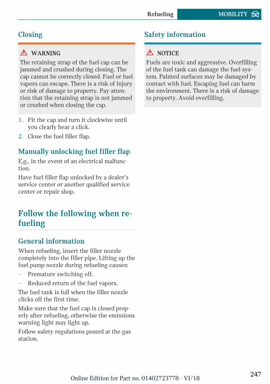
Closing
WARNING
The retaining strap of the fuel cap can bejammed and crushed during closing. Thecap cannot be correctly closed. Fuel or fuelvapors can escape. There is a risk of injuryor risk of damage to property. Pay atten-tion that the retaining strap is not jammedor crushed when closing the cap.
1. Fit the cap and turn it clockwise untilyou clearly hear a click.
2. Close the fuel filler flap.
Manually unlocking fuel filler flapE.g., in the event of an electrical malfunc-tion.
Have fuel filler flap unlocked by a dealer’sservice center or another qualified servicecenter or repair shop.
Follow the following when re-fueling
General informationWhen refueling, insert the filler nozzlecompletely into the filler pipe. Lifting up thefuel pump nozzle during refueling causes:
– Premature switching off.
– Reduced return of the fuel vapors.
The fuel tank is full when the filler nozzleclicks off the first time.
Make sure that the fuel cap is closed prop-erly after refueling, otherwise the emissionswarning light may light up.
Follow safety regulations posted at the gasstation.
Safety information
NOTICE
Fuels are toxic and aggressive. Overfillingof the fuel tank can damage the fuel sys-tem. Painted surfaces may be damaged bycontact with fuel. Escaping fuel can harmthe environment. There is a risk of damageto property. Avoid overfilling.
Seite 247
Refueling MOBILITY
247Online Edition for Part no. 01402723778 - VI/18
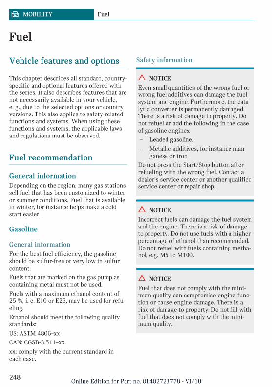
Fuel
Vehicle features and options
This chapter describes all standard, country-specific and optional features offered withthe series. It also describes features that arenot necessarily available in your vehicle,e. g., due to the selected options or countryversions. This also applies to safety-relatedfunctions and systems. When using thesefunctions and systems, the applicable lawsand regulations must be observed.
Fuel recommendation
General informationDepending on the region, many gas stationssell fuel that has been customized to winteror summer conditions. Fuel that is availablein winter, for instance helps make a coldstart easier.
Gasoline
General informationFor the best fuel efficiency, the gasolineshould be sulfur-free or very low in sulfurcontent.
Fuels that are marked on the gas pump ascontaining metal must not be used.
Fuels with a maximum ethanol content of25 %, i. e. E10 or E25, may be used for refu-eling.
Ethanol should meet the following qualitystandards:
US: ASTM 4806–xx
CAN: CGSB-3.511–xx
xx: comply with the current standard ineach case.
Safety information
NOTICE
Even small quantities of the wrong fuel orwrong fuel additives can damage the fuelsystem and engine. Furthermore, the cata-lytic converter is permanently damaged.There is a risk of damage to property. Donot refuel or add the following in the caseof gasoline engines:
– Leaded gasoline.
– Metallic additives, for instance man-ganese or iron.
Do not press the Start/Stop button afterrefueling with the wrong fuel. Contact adealer’s service center or another qualifiedservice center or repair shop.
NOTICE
Incorrect fuels can damage the fuel systemand the engine. There is a risk of damageto property. Do not use fuels with a higherpercentage of ethanol than recommended.Do not refuel with fuels containing metha-nol, e.g. M5 to M100.
NOTICE
Fuel that does not comply with the mini-mum quality can compromise engine func-tion or cause engine damage. There is arisk of damage to property. Do not fill withfuel that does not comply with the mini-mum quality.
Seite 248
MOBILITY Fuel
248Online Edition for Part no. 01402723778 - VI/18
CAUTION
The use of poor-quality fuels may result inharmful engine deposits or damage. Addi-tionally, problems relating to drivability,starting and stalling, especially under cer-tain environmental conditions such ashigh ambient temperature and high alti-tude, may occur.
If drivability problems are encountered,we recommend switching to a high qualitygasoline brand and a higher octane grade— AKI number — for a few tank fills. Toavoid harmful engine deposits, it is highlyrecommended to purchase gasoline fromTop Tier retailers.
Failure to comply with these recommenda-tions may result in the need for unsched-uled maintenance.
Recommended fuel gradeMINI recommends AKI 91.
John Cooper Works:
MINI recommends AKI 93.
Refuel with this gasoline to achieve therated performance and consumption values.
Minimum fuel gradeMINI recommends AKI 89.
John Cooper Works:
MINI recommends AKI 91.
If you use gasoline with this minimum AKIRating, the engine may produce knockingsounds when starting at high external tem-peratures. This has no effect on the enginelife.
Seite 249
Fuel MOBILITY
249Online Edition for Part no. 01402723778 - VI/18
Wheels and tires
Vehicle features and options
This chapter describes all standard, country-specific and optional features offered withthe series. It also describes features that arenot necessarily available in your vehicle,e. g., due to the selected options or countryversions. This also applies to safety-relatedfunctions and systems. When using thesefunctions and systems, the applicable lawsand regulations must be observed.
Tire inflation pressure
General informationThe tire characteristics and tire inflationpressure influence the following:
– The service life of the tires.
– Road safety.
– Driving comfort.
– Fuel consumption.
Safety information
WARNING
A tire with too little or no tire inflationpressure may heat up significantly andsustain damage. This will have a negativeimpact on aspects of handling, such assteering and braking response. There is arisk of an accident. Regularly check thetire inflation pressure, and correct it asneeded, for instance twice a month and be-fore a long trip.
Tire inflation pressurespecifications
In the tire inflation pressure tableThe tire inflation pressure table, refer topage 252, contains all tire inflation pres-sure specifications for the specified tiresizes at the ambient temperature. The tireinflation pressure values apply to tire sizesapproved by the manufacturer of the vehiclefor the vehicle type.
To identify the correct tire inflation pres-sure, please note the following:
– Tire sizes of your vehicle.
– Maximum permitted driving speed.
Checking the tire inflation pressure
General informationTires heat up while driving. The tire infla-tion pressure increases with the tire tem-perature.
Tires have a natural, consistent loss of tireinflation pressure.
The displays of inflation devices may under-read by up to 0.1 bar/2 psi.
Checking using tire inflation pressurespecifications in the tire inflationpressure tableThe tire inflation pressure specifications inthe tire inflation pressure table only relateto cold tires or tires at the same tempera-ture as the ambient temperature.
Only check the tire inflation pressure levelswhen the tires are cold, i.e.:
– Driving range of max. 1.25 miles/2 kmhas not been exceeded.
Seite 250
MOBILITY Wheels and tires
250Online Edition for Part no. 01402723778 - VI/18
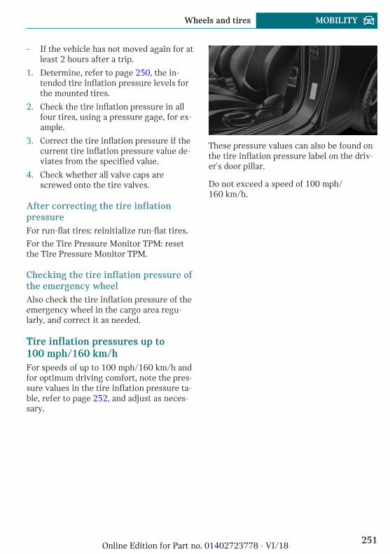
– If the vehicle has not moved again for atleast 2 hours after a trip.
1. Determine, refer to page 250, the in-tended tire inflation pressure levels forthe mounted tires.
2. Check the tire inflation pressure in allfour tires, using a pressure gage, for ex-ample.
3. Correct the tire inflation pressure if thecurrent tire inflation pressure value de-viates from the specified value.
4. Check whether all valve caps arescrewed onto the tire valves.
After correcting the tire inflationpressureFor run-flat tires: reinitialize run-flat tires.
For the Tire Pressure Monitor TPM: resetthe Tire Pressure Monitor TPM.
Checking the tire inflation pressure ofthe emergency wheelAlso check the tire inflation pressure of theemergency wheel in the cargo area regu-larly, and correct it as needed.
Tire inflation pressures up to100 mph/160 km/hFor speeds of up to 100 mph/160 km/h andfor optimum driving comfort, note the pres-sure values in the tire inflation pressure ta-ble, refer to page 252, and adjust as neces-sary.
These pressure values can also be found onthe tire inflation pressure label on the driv-er's door pillar.
Do not exceed a speed of 100 mph/160 km/h.
Seite 251
Wheels and tires MOBILITY
251Online Edition for Part no. 01402723778 - VI/18
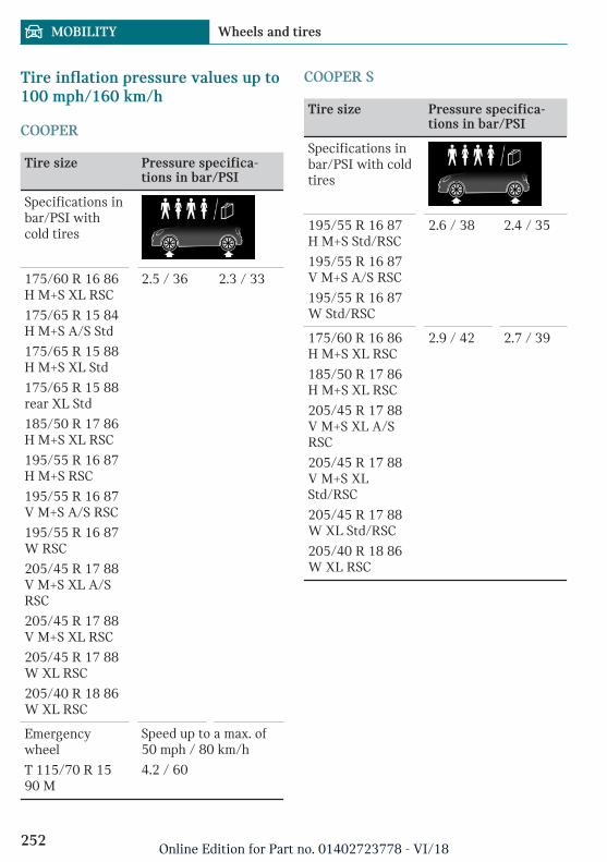
Tire inflation pressure values up to100 mph/160 km/h
COOPER
Tire size Pressure specifica-tions in bar/PSI
Specifications inbar/PSI withcold tires
175/60 R 16 86H M+S XL RSC
175/65 R 15 84H M+S A/S Std
175/65 R 15 88H M+S XL Std
175/65 R 15 88rear XL Std
185/50 R 17 86H M+S XL RSC
195/55 R 16 87H M+S RSC
195/55 R 16 87V M+S A/S RSC
195/55 R 16 87W RSC
205/45 R 17 88V M+S XL A/SRSC
205/45 R 17 88V M+S XL RSC
205/45 R 17 88W XL RSC
205/40 R 18 86W XL RSC
2.5 / 36 2.3 / 33
Emergencywheel
T 115/70 R 1590 M
Speed up to a max. of50 mph / 80 km/h
4.2 / 60
COOPER S
Tire size Pressure specifica-tions in bar/PSI
Specifications inbar/PSI with coldtires
195/55 R 16 87H M+S Std/RSC
195/55 R 16 87V M+S A/S RSC
195/55 R 16 87W Std/RSC
2.6 / 38 2.4 / 35
175/60 R 16 86H M+S XL RSC
185/50 R 17 86H M+S XL RSC
205/45 R 17 88V M+S XL A/SRSC
205/45 R 17 88V M+S XLStd/RSC
205/45 R 17 88W XL Std/RSC
205/40 R 18 86W XL RSC
2.9 / 42 2.7 / 39
Seite 252
MOBILITY Wheels and tires
252Online Edition for Part no. 01402723778 - VI/18
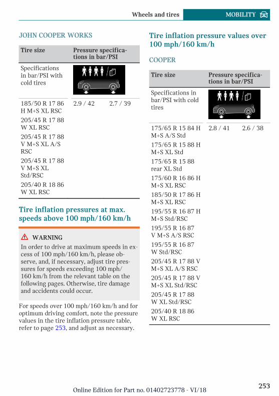
JOHN COOPER WORKS
Tire size Pressure specifica-tions in bar/PSI
Specificationsin bar/PSI withcold tires
185/50 R 17 86H M+S XL RSC
205/45 R 17 88W XL RSC
205/45 R 17 88V M+S XL A/SRSC
205/45 R 17 88V M+S XLStd/RSC
205/40 R 18 86W XL RSC
2.9 / 42 2.7 / 39
Tire inflation pressures at max.speeds above 100 mph/160 km/h
WARNING
In order to drive at maximum speeds in ex-cess of 100 mph/160 km/h, please ob-serve, and, if necessary, adjust tire pres-sures for speeds exceeding 100 mph/160 km/h from the relevant table on thefollowing pages. Otherwise, tire damageand accidents could occur.
For speeds over 100 mph/160 km/h and foroptimum driving comfort, note the pressurevalues in the tire inflation pressure table,refer to page 253, and adjust as necessary.
Tire inflation pressure values over100 mph/160 km/h
COOPER
Tire size Pressure specifica-tions in bar/PSI
Specifications inbar/PSI with coldtires
175/65 R 15 84 HM+S A/S Std
175/65 R 15 88 HM+S XL Std
175/65 R 15 88rear XL Std
175/60 R 16 86 HM+S XL RSC
185/50 R 17 86 HM+S XL RSC
195/55 R 16 87 HM+S Std/RSC
195/55 R 16 87V M+S A/S RSC
195/55 R 16 87W Std/RSC
205/45 R 17 88 VM+S XL A/S RSC
205/45 R 17 88 VM+S XL Std/RSC
205/45 R 17 88W XL Std/RSC
205/40 R 18 86W XL RSC
2.8 / 41 2.6 / 38
Seite 253
Wheels and tires MOBILITY
253Online Edition for Part no. 01402723778 - VI/18
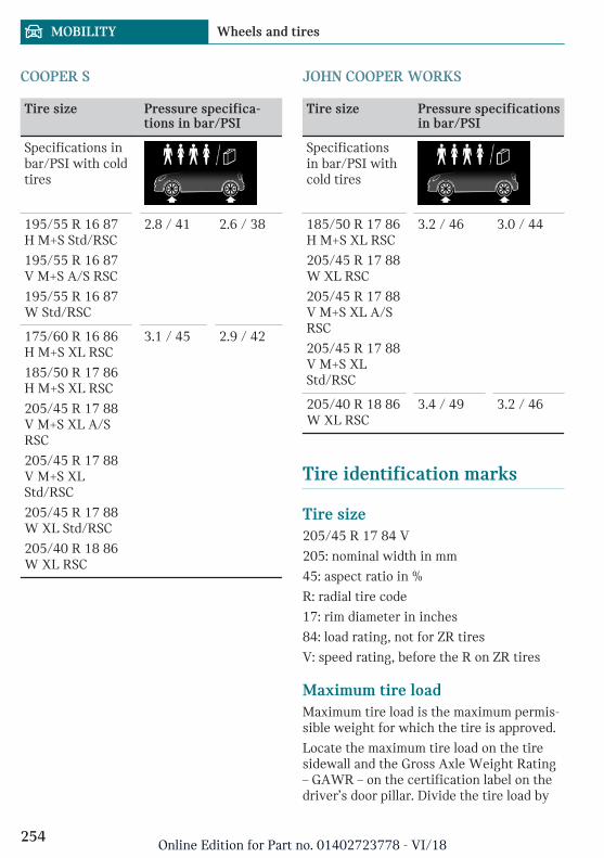
COOPER S
Tire size Pressure specifica-tions in bar/PSI
Specifications inbar/PSI with coldtires
195/55 R 16 87H M+S Std/RSC
195/55 R 16 87V M+S A/S RSC
195/55 R 16 87W Std/RSC
2.8 / 41 2.6 / 38
175/60 R 16 86H M+S XL RSC
185/50 R 17 86H M+S XL RSC
205/45 R 17 88V M+S XL A/SRSC
205/45 R 17 88V M+S XLStd/RSC
205/45 R 17 88W XL Std/RSC
205/40 R 18 86W XL RSC
3.1 / 45 2.9 / 42
JOHN COOPER WORKS
Tire size Pressure specificationsin bar/PSI
Specificationsin bar/PSI withcold tires
185/50 R 17 86H M+S XL RSC
205/45 R 17 88W XL RSC
205/45 R 17 88V M+S XL A/SRSC
205/45 R 17 88V M+S XLStd/RSC
3.2 / 46 3.0 / 44
205/40 R 18 86W XL RSC
3.4 / 49 3.2 / 46
Tire identification marks
Tire size205/45 R 17 84 V
205: nominal width in mm
45: aspect ratio in %
R: radial tire code
17: rim diameter in inches
84: load rating, not for ZR tires
V: speed rating, before the R on ZR tires
Maximum tire loadMaximum tire load is the maximum permis-sible weight for which the tire is approved.
Locate the maximum tire load on the tiresidewall and the Gross Axle Weight Rating– GAWR – on the certification label on thedriver’s door pillar. Divide the tire load by
Seite 254
MOBILITY Wheels and tires
254Online Edition for Part no. 01402723778 - VI/18
1.1. It must be greater than one-half of thevehicle’s Gross Axle Weight Rating –GAWR. Note, front vs. rear GAWR and tireloads, respectively.
Speed letterQ = up to 100 mph/160 km/h
R = 106 mph/170 km/h
S = up to 112 mph/180 km/h
T = up to 118 mph/190 km/h
H = up to 131 mph/210 km/h
V = up to 150 mph/240 km/h
W = up to 167 mph/270 km/h
Y = up to 186 mph/300 km/h
Tire Identification NumberDOT code: DOT xxxx xxx 2118
xxxx: manufacturer code for the tire brand
xxx: tire size and tire design
2118: tire age
Tires with DOT codes meet the guidelinesof the U.S. Department of Transportation.
Tire age
RecommendationRegardless of the tire tread, replace tires atleast every 6 years.
Manufacture dateYou can find the manufacture date of thetire on the tire's sidewall.
Designation Manufacture date
DOT … 2118 21st week 2018
Uniform Tire Quality GradingQuality grades can be found where applica-ble on the tire sidewall between treadshoulder and maximum section width.
E.g.: Treadwear 200; Traction AA; Tempera-ture A
DOT Quality GradesTreadwear
Traction AA A B C
Temperature A B C
All passenger vehicle tires must conform toFederal Safety Requirements in addition tothese grades.
TreadwearThe treadwear grade is a comparative ratingbased on the wear rate of the tire whentested under controlled conditions on aspecified government test course. E.g., atire graded 150 would wear one and one-half, 1 g, times as well on the governmentcourse as a tire graded 100. The relativeperformance of tires depends upon the ac-tual conditions of their use, however, andmay depart significantly from the norm dueto variations in driving habits, service prac-tices and differences in road characteristicsand climate.
TractionThe traction grades, from highest to lowest,are AA, A, B, and C.
Those grades represent the tire's ability tostop on wet pavement as measured undercontrolled conditions on specified govern-ment test surfaces of asphalt and concrete.A tire marked C may have poor traction per-formance.
The traction grade assigned to this tire isbased on straight-ahead braking tractiontests, and does not include acceleration,cornering, hydroplaning, or peak tractioncharacteristics.
Seite 255
Wheels and tires MOBILITY
255Online Edition for Part no. 01402723778 - VI/18
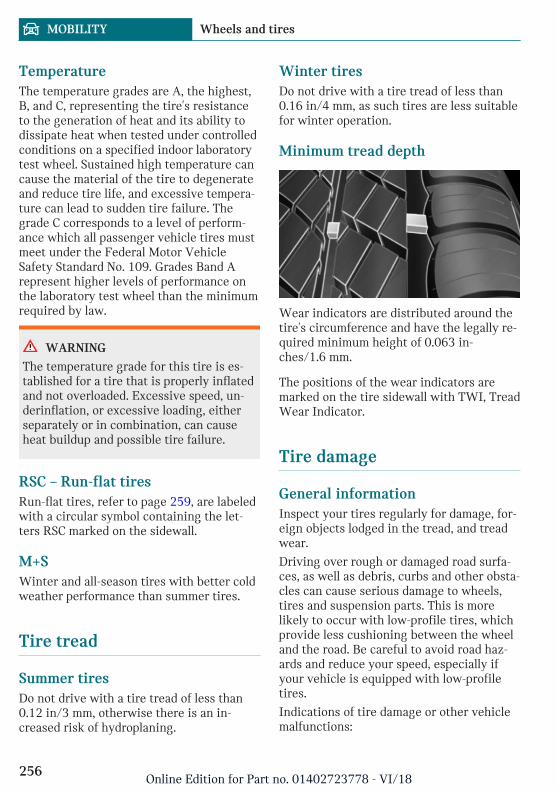
TemperatureThe temperature grades are A, the highest,B, and C, representing the tire's resistanceto the generation of heat and its ability todissipate heat when tested under controlledconditions on a specified indoor laboratorytest wheel. Sustained high temperature cancause the material of the tire to degenerateand reduce tire life, and excessive tempera-ture can lead to sudden tire failure. Thegrade C corresponds to a level of perform-ance which all passenger vehicle tires mustmeet under the Federal Motor VehicleSafety Standard No. 109. Grades Band Arepresent higher levels of performance onthe laboratory test wheel than the minimumrequired by law.
WARNING
The temperature grade for this tire is es-tablished for a tire that is properly inflatedand not overloaded. Excessive speed, un-derinflation, or excessive loading, eitherseparately or in combination, can causeheat buildup and possible tire failure.
RSC – Run-flat tiresRun-flat tires, refer to page 259, are labeledwith a circular symbol containing the let-ters RSC marked on the sidewall.
M+SWinter and all-season tires with better coldweather performance than summer tires.
Tire tread
Summer tiresDo not drive with a tire tread of less than0.12 in/3 mm, otherwise there is an in-creased risk of hydroplaning.
Winter tiresDo not drive with a tire tread of less than0.16 in/4 mm, as such tires are less suitablefor winter operation.
Minimum tread depth
Wear indicators are distributed around thetire's circumference and have the legally re-quired minimum height of 0.063 in-ches/1.6 mm.
The positions of the wear indicators aremarked on the tire sidewall with TWI, TreadWear Indicator.
Tire damage
General informationInspect your tires regularly for damage, for-eign objects lodged in the tread, and treadwear.
Driving over rough or damaged road surfa-ces, as well as debris, curbs and other obsta-cles can cause serious damage to wheels,tires and suspension parts. This is morelikely to occur with low-profile tires, whichprovide less cushioning between the wheeland the road. Be careful to avoid road haz-ards and reduce your speed, especially ifyour vehicle is equipped with low-profiletires.
Indications of tire damage or other vehiclemalfunctions:
Seite 256
MOBILITY Wheels and tires
256Online Edition for Part no. 01402723778 - VI/18

– Unusual vibrations.
– Unusual tire or running noises.
– Unusual handling such as a strong ten-dency to pull to the left or right.
Damage can be caused by the following sit-uations, for instance:
– Driving over curbs.
– Road damage.
– Tire inflation pressure too low.
– Vehicle overloading.
– Incorrect tire storage.
Safety information
WARNING
Damaged tires can lose tire inflation pres-sure, which can lead to loss of vehicle con-trol. There is a risk of an accident. If tiredamage is suspected while driving, imme-diately reduce speed and stop. Havewheels and tires checked. For this pur-pose, drive carefully to the nearest dealer’sservice center or another qualified servicecenter or repair shop. Have vehicle towedor transported as needed. Do not repairdamaged tires, but have them replaced.
WARNING
Tires can become damaged by driving overobstacles, e.g., curbs or road damage, athigh speed. Larger wheels have a smallertire cross-section. The smaller the tirecross-section, the higher the risk of tiredamage. There is a danger of accidents andproperty damage. If possible, drive aroundobstacles, or drive over them slowly andcarefully.
Changing wheels and tires
Mounting and wheel balancingHave mounting and wheel balancing carriedout by a dealer’s service center or anotherqualified service center or repair shop.
Wheel and tire combination
General informationYou can ask the dealer’s service center oranother qualified service center or repairshop about the correct wheel/tire combina-tion and wheel rim versions for the vehicle.
Safety information
WARNING
Wheels and tires which are not suitablefor your vehicle can damage parts of thevehicle, for instance due to contact withthe body due to tolerances despite thesame official size rating. There is a risk ofan accident. The manufacturer of your ve-hicle strongly suggests that you usewheels and tires that have been recom-mended by the vehicle manufacturer foryour vehicle type.
WARNING
Incorrect wheel/tire combinations willhave a negative impact on the vehicle'shandling and on the function of a varietyof systems, such as the Anti-lock BrakeSystem or Dynamic Stability Control.There is a risk of an accident. To maintaingood handling and vehicle response, useonly tires with a single tread configurationfrom a single manufacturer. The manufac-turer of the vehicle recommends that youuse wheels and tires that have been rec-ommended by the vehicle manufacturer
Seite 257
Wheels and tires MOBILITY
257Online Edition for Part no. 01402723778 - VI/18
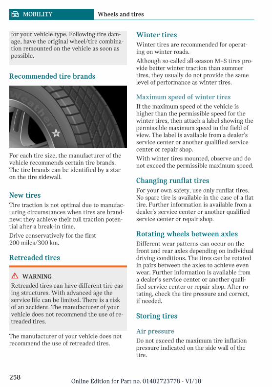
for your vehicle type. Following tire dam-age, have the original wheel/tire combina-tion remounted on the vehicle as soon aspossible.
Recommended tire brands
For each tire size, the manufacturer of thevehicle recommends certain tire brands.The tire brands can be identified by a staron the tire sidewall.
New tiresTire traction is not optimal due to manufac-turing circumstances when tires are brand-new; they achieve their full traction poten-tial after a break-in time.
Drive conservatively for the first200 miles/300 km.
Retreaded tires
WARNING
Retreaded tires can have different tire cas-ing structures. With advanced age theservice life can be limited. There is a riskof an accident. The manufacturer of yourvehicle does not recommend the use of re-treaded tires.
The manufacturer of your vehicle does notrecommend the use of retreaded tires.
Winter tiresWinter tires are recommended for operat-ing on winter roads.
Although so-called all-season M+S tires pro-vide better winter traction than summertires, they usually do not provide the samelevel of performance as winter tires.
Maximum speed of winter tiresIf the maximum speed of the vehicle ishigher than the permissible speed for thewinter tires, then attach a label showing thepermissible maximum speed in the field ofview. The label is available from a dealer’sservice center or another qualified servicecenter or repair shop.
With winter tires mounted, observe and donot exceed the permissible maximum speed.
Changing runflat tiresFor your own safety, use only runflat tires.No spare tire is available in the case of a flattire. Further information is available from adealer’s service center or another qualifiedservice center or repair shop.
Rotating wheels between axlesDifferent wear patterns can occur on thefront and rear axles depending on individualdriving conditions. The tires can be rotatedin pairs between the axles to achieve evenwear. Further information is available froma dealer’s service center or another quali-fied service center or repair shop. After ro-tating, check the tire pressure and correct,if needed.
Storing tires
Air pressureDo not exceed the maximum tire inflationpressure indicated on the side wall of thetire.
Seite 258
MOBILITY Wheels and tires
258Online Edition for Part no. 01402723778 - VI/18
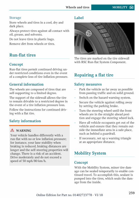
StorageStore wheels and tires in a cool, dry anddark place.
Always protect tires against all contact withoil, grease, and solvents.
Do not leave tires in plastic bags.
Remove dirt from wheels or tires.
Run-flat tires
ConceptRun-flat tires permit continued driving un-der restricted conditions even in the eventof a complete loss of tire inflation pressure.
General informationThe wheels are composed of tires that areself-supporting to a limited degree.
The support of the sidewall allows the tireto remain drivable to a restricted degree inthe event of a tire inflation pressure loss.
Follow the instructions for continued driv-ing with a flat tire.
Safety information
WARNING
Your vehicle handles differently with arun-flat with no or low inflation pressure;for instance, your lane stability whenbraking is reduced, braking distances arelonger and the self-steering properties willchange. There is a risk of an accident.Drive moderately and do not exceed aspeed of 50 mph/80 km/h.
Label
The tires are marked on the tire sidewallwith RSC Run-flat System Component.
Repairing a flat tire
Safety measures– Park the vehicle as far away as possible
from passing traffic and on solid ground.
– Switch on the hazard warning system.
– Secure the vehicle against rolling awayby setting the parking brake.
– Turn the steering wheel until the frontwheels are in the straight-ahead posi-tion and engage the steering wheel lock.
– Have all vehicle occupants get out of thevehicle and ensure that they remain out-side the immediate area in a safe place,such as behind a guardrail.
– If necessary, set up a warning triangleat an appropriate distance.
Mobility System
ConceptWith the Mobility System, minor tire dam-age can be sealed temporarily to enable con-tinued travel. To accomplish this, sealant ispumped into the tires, which seals the dam-age from the inside.
Seite 259
Wheels and tires MOBILITY
259Online Edition for Part no. 01402723778 - VI/18
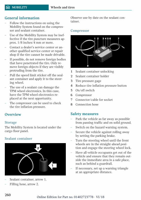
General information– Follow the instructions on using the
Mobility System found on the compres-sor and sealant container.
– Use of the Mobility System may be inef-fective if the tire puncture measures ap-prox. 1/8 inches/4 mm or more.
– Contact a dealer’s service center or an-other qualified service center or repairshop if the tire cannot be made drivable.
– If possible, do not remove foreign bodiesthat have penetrated the tire. Only re-move foreign objects if they are visiblyprotruding from the tire.
– Pull the speed limit sticker off the seal-ant container and apply it to the steer-ing wheel.
– The use of a sealant can damage theTPM wheel electronics. In this case,have the TPM wheel electronics re-placed at the next opportunity.
– The compressor can be used to checkthe tire inflation pressure.
Overview
StorageThe Mobility System is located under thecargo floor panel.
Sealant container
– Sealant container, arrow 1.
– Filling hose, arrow 2.
Observe use-by date on the sealant con-tainer.
Compressor
1 Sealant container unlocking
2 Sealant container holder
3 Tire pressure gage
4 Reduce tire inflation pressure button
5 On/off switch
6 Compressor
7 Connector/cable for socket
8 Connection hose
Safety measures– Park the vehicle as far away as possible
from passing traffic and on solid ground.
– Switch on the hazard warning system.
– Secure the vehicle against rolling awayby setting the parking brake.
– Turn the steering wheel until the frontwheels are in the straight-ahead posi-tion and engage the steering wheel lock.
– Have all vehicle occupants get out of thevehicle and ensure that they remain out-side the immediate area in a safe place,such as behind a guardrail.
– If necessary, set up a warning triangleat an appropriate distance.
Seite 260
MOBILITY Wheels and tires
260Online Edition for Part no. 01402723778 - VI/18
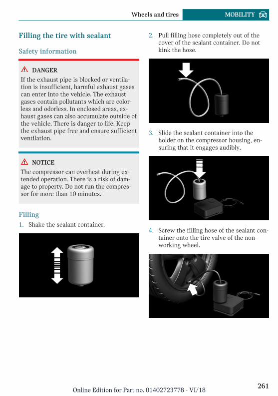
Filling the tire with sealant
Safety information
DANGER
If the exhaust pipe is blocked or ventila-tion is insufficient, harmful exhaust gasescan enter into the vehicle. The exhaustgases contain pollutants which are color-less and odorless. In enclosed areas, ex-haust gases can also accumulate outside ofthe vehicle. There is danger to life. Keepthe exhaust pipe free and ensure sufficientventilation.
NOTICE
The compressor can overheat during ex-tended operation. There is a risk of dam-age to property. Do not run the compres-sor for more than 10 minutes.
Filling1. Shake the sealant container.
2. Pull filling hose completely out of thecover of the sealant container. Do notkink the hose.
3. Slide the sealant container into theholder on the compressor housing, en-suring that it engages audibly.
4. Screw the filling hose of the sealant con-tainer onto the tire valve of the non-working wheel.
Seite 261
Wheels and tires MOBILITY
261Online Edition for Part no. 01402723778 - VI/18
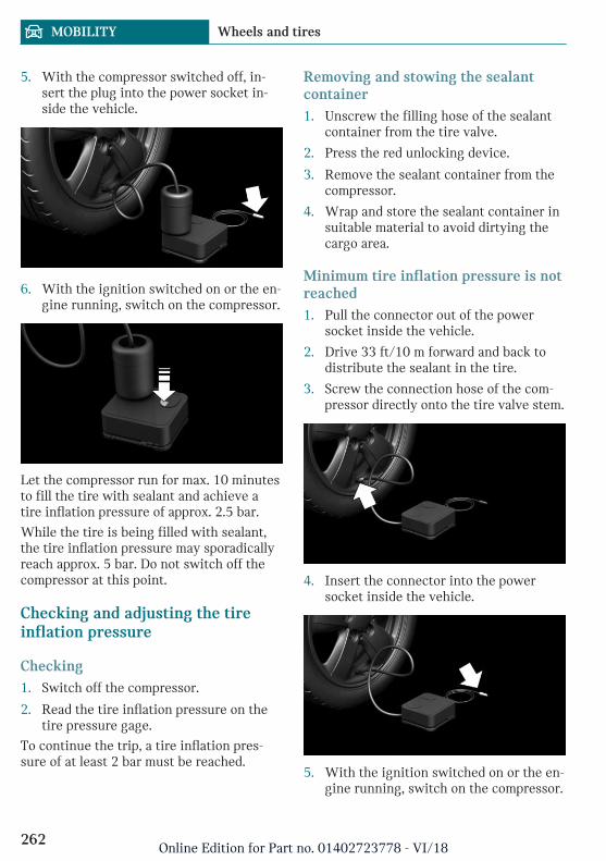
5. With the compressor switched off, in-sert the plug into the power socket in-side the vehicle.
6. With the ignition switched on or the en-gine running, switch on the compressor.
Let the compressor run for max. 10 minutesto fill the tire with sealant and achieve atire inflation pressure of approx. 2.5 bar.
While the tire is being filled with sealant,the tire inflation pressure may sporadicallyreach approx. 5 bar. Do not switch off thecompressor at this point.
Checking and adjusting the tireinflation pressure
Checking1. Switch off the compressor.
2. Read the tire inflation pressure on thetire pressure gage.
To continue the trip, a tire inflation pres-sure of at least 2 bar must be reached.
Removing and stowing the sealantcontainer1. Unscrew the filling hose of the sealant
container from the tire valve.
2. Press the red unlocking device.
3. Remove the sealant container from thecompressor.
4. Wrap and store the sealant container insuitable material to avoid dirtying thecargo area.
Minimum tire inflation pressure is notreached1. Pull the connector out of the power
socket inside the vehicle.
2. Drive 33 ft/10 m forward and back todistribute the sealant in the tire.
3. Screw the connection hose of the com-pressor directly onto the tire valve stem.
4. Insert the connector into the powersocket inside the vehicle.
5. With the ignition switched on or the en-gine running, switch on the compressor.
Seite 262
MOBILITY Wheels and tires
262Online Edition for Part no. 01402723778 - VI/18
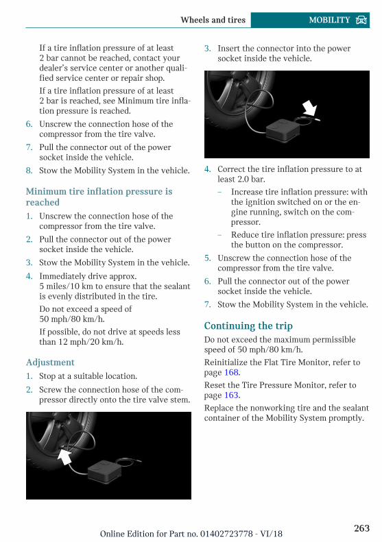
If a tire inflation pressure of at least2 bar cannot be reached, contact yourdealer’s service center or another quali-fied service center or repair shop.
If a tire inflation pressure of at least2 bar is reached, see Minimum tire infla-tion pressure is reached.
6. Unscrew the connection hose of thecompressor from the tire valve.
7. Pull the connector out of the powersocket inside the vehicle.
8. Stow the Mobility System in the vehicle.
Minimum tire inflation pressure isreached1. Unscrew the connection hose of the
compressor from the tire valve.
2. Pull the connector out of the powersocket inside the vehicle.
3. Stow the Mobility System in the vehicle.
4. Immediately drive approx.5 miles/10 km to ensure that the sealantis evenly distributed in the tire.
Do not exceed a speed of50 mph/80 km/h.
If possible, do not drive at speeds lessthan 12 mph/20 km/h.
Adjustment1. Stop at a suitable location.
2. Screw the connection hose of the com-pressor directly onto the tire valve stem.
3. Insert the connector into the powersocket inside the vehicle.
4. Correct the tire inflation pressure to atleast 2.0 bar.
– Increase tire inflation pressure: withthe ignition switched on or the en-gine running, switch on the com-pressor.
– Reduce tire inflation pressure: pressthe button on the compressor.
5. Unscrew the connection hose of thecompressor from the tire valve.
6. Pull the connector out of the powersocket inside the vehicle.
7. Stow the Mobility System in the vehicle.
Continuing the tripDo not exceed the maximum permissiblespeed of 50 mph/80 km/h.
Reinitialize the Flat Tire Monitor, refer topage 168.
Reset the Tire Pressure Monitor, refer topage 163.
Replace the nonworking tire and the sealantcontainer of the Mobility System promptly.
Seite 263
Wheels and tires MOBILITY
263Online Edition for Part no. 01402723778 - VI/18
Snow chains
Safety information
WARNING
With the mounting of snow chains on un-suitable tires, the snow chains can comeinto contact with vehicle parts. There is arisk of accidents or risk of damage to prop-erty. Only mount snow chains on tires thatare designated by their manufacturer assuitable for the use of snow chains.
WARNING
Insufficiently tight snow chains may dam-age tires and vehicle components. There isa risk of accidents or risk of damage toproperty. Make sure that the snow chainsare always sufficiently tight. Re-tighten asneeded according to the snow chain manu-facturer's instructions.
Fine-link snow chainsThe manufacturer of your vehicle recom-mends use of fine-link snow chains. Certaintypes of fine-link snow chains have beentested by the manufacturer of the vehicleand recommended as road-safe and suitable.
Information regarding suitable snow chainsis available from a dealer’s service center oranother qualified service center or repairshop.
UseUse only in pairs on the front wheels, equip-ped with the tires of the following size:
– 175/65 R 15.
– 175/60 R 16.
– 185/50 R 17.
John Cooper Works:
185/50 R 17.
Follow the snow chain manufacturer's in-structions.
Do not initialize the run-flat tires aftermounting snow chains, as doing so may re-sult in incorrect readings.
Do not reset the Tire Pressure Monitor TPMafter mounting snow chains, as doing somay result in incorrect readings.
When driving with snow chains, briefly ac-tivate Dynamic Traction Control DTC, ifneeded.
Maximum speed with snow chainsDo not exceed a speed of 30 mph/50 km/hwhen using snow chains.
Changing wheels/tires
General informationWhen using run-flat tires or a flat tire kit, awheel does not always need to be changedimmediately when there is a loss of tire in-flation pressure due to a flat tire.
If needed, the tools for changing wheels areavailable as accessories from a dealer’sservice center or another qualified servicecenter or repair shop.
Safety information
DANGER
The vehicle jack is only provided for short-term lifting of the vehicle for wheelchanges. Even if all safety measures areobserved, there is a risk of the raised vehi-cle falling, if the vehicle jack tips over.There is a risk of injuries or danger to life.If the vehicle is raised, do not lie under thevehicle and do not start the engine.
Seite 264
MOBILITY Wheels and tires
264Online Edition for Part no. 01402723778 - VI/18
DANGER
Supports such as wooden blocks under thevehicle jack reduce the capacity of the ve-hicle jack to bear weight. They have thepotential to exert too much strain on thevehicle jack, causing it to tip over and thevehicle to fall. There is a risk of injuries ordanger to life. Do not place supports underthe vehicle jack.
WARNING
The jack, issued by the vehicle manufac-turer, is provided in order to perform awheel change in the event of a breakdown.The jack is not designed for frequent use;for example, changing from summer towinter tires. Using the jack frequently maycause it to become jammed or damaged.There is a risk of injury and risk of damageto property. Only use the jack to attach anemergency or spare wheel in the event ofa breakdown.
WARNING
On soft, uneven or slippery ground, for ex-ample snow, ice, tiles, etc., the vehicle jackcan slip away. There is a risk of injury. Ifpossible, change the wheel on a flat, solid,and slip-resistant surface.
WARNING
The vehicle jack is optimized for liftingthe vehicle and for the jacking points onthe vehicle only. There is a risk of injury.Do not lift any other vehicle or cargo usingthe vehicle jack.
WARNING
If the vehicle jack is not inserted into thejacking point provided for this purpose,the vehicle may be damaged or the vehiclejack may slip when it is being cranked up.There is a risk of injury or risk of damageto property. When cranking up the vehiclejack, ensure that it is inserted in the jack-ing point next to the wheel housing.
WARNING
A vehicle that is raised on a vehicle jackmay fall off of the jack if lateral forces areexerted on it. There is a risk of injury andrisk of damage to property. While the ve-hicle is raised, do not exert lateral forceson the vehicle or pull abruptly on the vehi-cle. Have a stuck wheel removed by a deal-er’s service center or another qualifiedservice center or repair shop.
Securing the vehicle against rolling
General informationThe vehicle manufacturer recommends toadditionally secure the vehicle against roll-ing away when changing a wheel.
Seite 265
Wheels and tires MOBILITY
265Online Edition for Part no. 01402723778 - VI/18
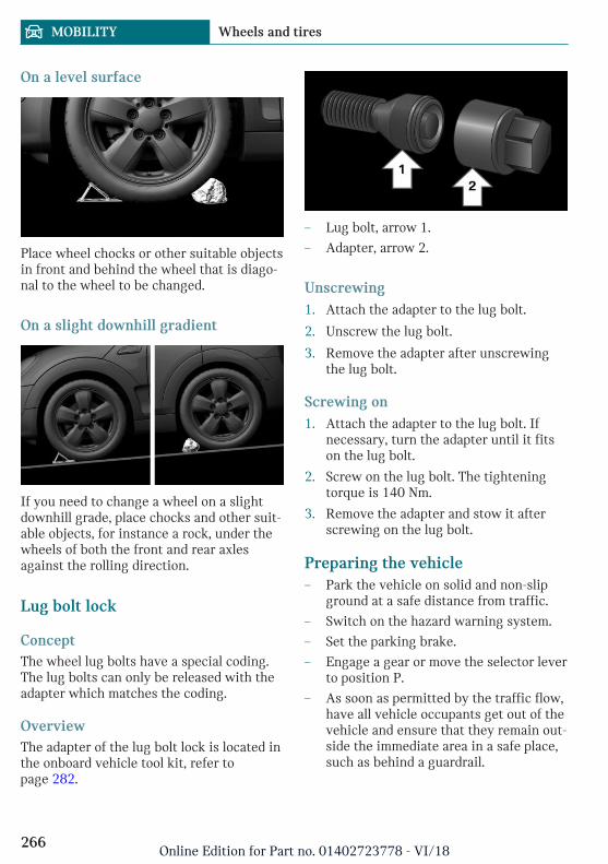
On a level surface
Place wheel chocks or other suitable objectsin front and behind the wheel that is diago-nal to the wheel to be changed.
On a slight downhill gradient
If you need to change a wheel on a slightdownhill grade, place chocks and other suit-able objects, for instance a rock, under thewheels of both the front and rear axlesagainst the rolling direction.
Lug bolt lock
ConceptThe wheel lug bolts have a special coding.The lug bolts can only be released with theadapter which matches the coding.
OverviewThe adapter of the lug bolt lock is located inthe onboard vehicle tool kit, refer topage 282.
– Lug bolt, arrow 1.
– Adapter, arrow 2.
Unscrewing1. Attach the adapter to the lug bolt.
2. Unscrew the lug bolt.
3. Remove the adapter after unscrewingthe lug bolt.
Screwing on1. Attach the adapter to the lug bolt. If
necessary, turn the adapter until it fitson the lug bolt.
2. Screw on the lug bolt. The tighteningtorque is 140 Nm.
3. Remove the adapter and stow it afterscrewing on the lug bolt.
Preparing the vehicle– Park the vehicle on solid and non-slip
ground at a safe distance from traffic.
– Switch on the hazard warning system.
– Set the parking brake.
– Engage a gear or move the selector leverto position P.
– As soon as permitted by the traffic flow,have all vehicle occupants get out of thevehicle and ensure that they remain out-side the immediate area in a safe place,such as behind a guardrail.
Seite 266
MOBILITY Wheels and tires
266Online Edition for Part no. 01402723778 - VI/18
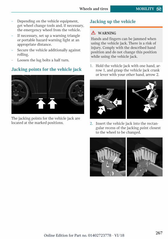
– Depending on the vehicle equipment,get wheel change tools and, if necessary,the emergency wheel from the vehicle.
– If necessary, set up a warning triangleor portable hazard warning light at anappropriate distance.
– Secure the vehicle additionally againstrolling.
– Loosen the lug bolts a half turn.
Jacking points for the vehicle jack
The jacking points for the vehicle jack arelocated at the marked positions.
Jacking up the vehicle
WARNING
Hands and fingers can be jammed whenusing the vehicle jack. There is a risk ofinjury. Comply with the described handposition and do not change this positionwhile using the vehicle jack.
1. Hold the vehicle jack with one hand, ar-row 1, and grasp the vehicle jack crankor lever with your other hand, arrow 2.
2. Insert the vehicle jack into the rectan-gular recess of the jacking point closestto the wheel to be changed.
Seite 267
Wheels and tires MOBILITY
267Online Edition for Part no. 01402723778 - VI/18
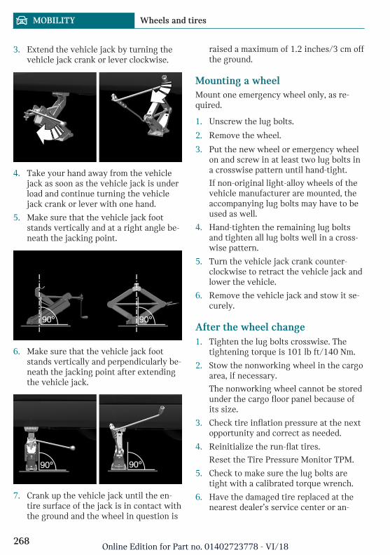
3. Extend the vehicle jack by turning thevehicle jack crank or lever clockwise.
4. Take your hand away from the vehiclejack as soon as the vehicle jack is underload and continue turning the vehiclejack crank or lever with one hand.
5. Make sure that the vehicle jack footstands vertically and at a right angle be-neath the jacking point.
6. Make sure that the vehicle jack footstands vertically and perpendicularly be-neath the jacking point after extendingthe vehicle jack.
7. Crank up the vehicle jack until the en-tire surface of the jack is in contact withthe ground and the wheel in question is
raised a maximum of 1.2 inches/3 cm offthe ground.
Mounting a wheelMount one emergency wheel only, as re-quired.
1. Unscrew the lug bolts.
2. Remove the wheel.
3. Put the new wheel or emergency wheelon and screw in at least two lug bolts ina crosswise pattern until hand-tight.
If non-original light-alloy wheels of thevehicle manufacturer are mounted, theaccompanying lug bolts may have to beused as well.
4. Hand-tighten the remaining lug boltsand tighten all lug bolts well in a cross-wise pattern.
5. Turn the vehicle jack crank counter-clockwise to retract the vehicle jack andlower the vehicle.
6. Remove the vehicle jack and stow it se-curely.
After the wheel change1. Tighten the lug bolts crosswise. The
tightening torque is 101 lb ft/140 Nm.
2. Stow the nonworking wheel in the cargoarea, if necessary.
The nonworking wheel cannot be storedunder the cargo floor panel because ofits size.
3. Check tire inflation pressure at the nextopportunity and correct as needed.
4. Reinitialize the run-flat tires.
Reset the Tire Pressure Monitor TPM.
5. Check to make sure the lug bolts aretight with a calibrated torque wrench.
6. Have the damaged tire replaced at thenearest dealer’s service center or an-
Seite 268
MOBILITY Wheels and tires
268Online Edition for Part no. 01402723778 - VI/18
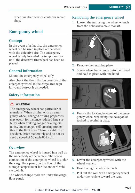
other qualified service center or repairshop.
Emergency wheel
ConceptIn the event of a flat tire, the emergencywheel can be used in place of the wheelwith the defective tire. The emergencywheel is only intended for temporary useuntil the defective tire/wheel has been re-placed.
General informationMount one emergency wheel only.
Also check the tire inflation pressure of theemergency wheel in the cargo area regu-larly, and correct it as needed.
Safety information
WARNING
The emergency wheel has particular di-mensions. When driving with an emer-gency wheel, changed driving propertiesmay occur, for instance reduced lane sta-bility when braking, longer braking dis-tance, and changed self-steering proper-ties in the limit area. There is a risk of anaccident. Drive moderately and do not ex-ceed a speed of 50 mph/80 km/h.
OverviewThe emergency wheel is housed in a well onthe underbody of the vehicle. The screwconnection of the emergency wheel is underthe cargo floor panel, on the floor of thestorage compartment for the onboard vehi-cle tool kit.
The wheel change tools are under the cargofloor panel.
Removing the emergency wheel1. Loosen the nut using the wheel wrench
from the onboard vehicle tool kit.
2. Remove the retaining plate.
3. Screw wheel lug wrench onto the threadand hold in place with one hand.
4. Unlock the locking hexagon of the emer-gency wheel well using the hexagon at-tached to retaining plate.
5. Lower the emergency wheel with thewheel wrench.
6. Unscrewing the wheel wrench
7. Pull out the well with emergency wheelunder the vehicle toward the rear.
Seite 269
Wheels and tires MOBILITY
269Online Edition for Part no. 01402723778 - VI/18
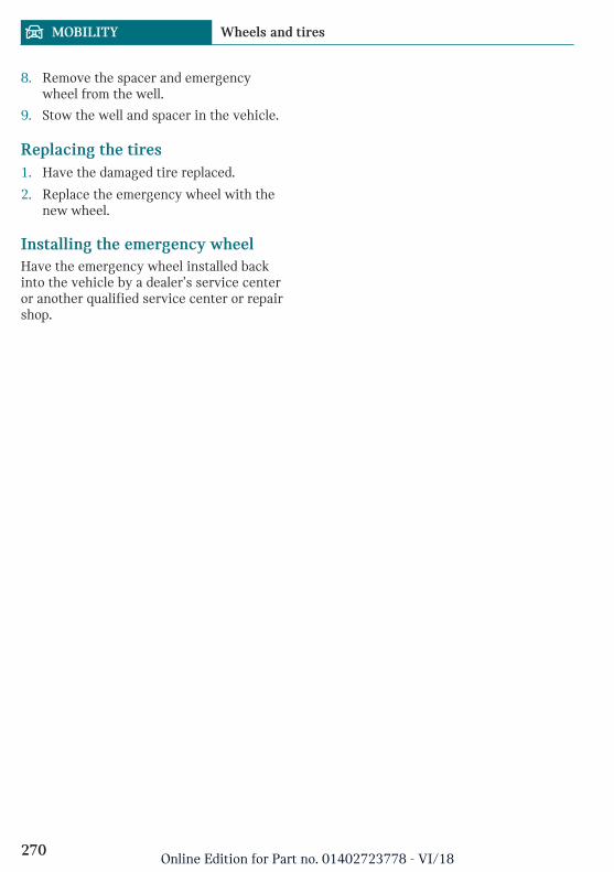
8. Remove the spacer and emergencywheel from the well.
9. Stow the well and spacer in the vehicle.
Replacing the tires1. Have the damaged tire replaced.
2. Replace the emergency wheel with thenew wheel.
Installing the emergency wheelHave the emergency wheel installed backinto the vehicle by a dealer’s service centeror another qualified service center or repairshop.
Seite 270
MOBILITY Wheels and tires
270Online Edition for Part no. 01402723778 - VI/18
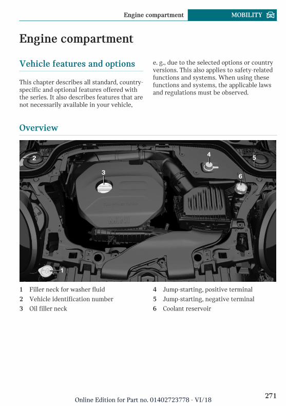
Engine compartment
Vehicle features and options
This chapter describes all standard, country-specific and optional features offered withthe series. It also describes features that arenot necessarily available in your vehicle,
e. g., due to the selected options or countryversions. This also applies to safety-relatedfunctions and systems. When using thesefunctions and systems, the applicable lawsand regulations must be observed.
Overview
1 Filler neck for washer fluid
2 Vehicle identification number
3 Oil filler neck
4 Jump-starting, positive terminal
5 Jump-starting, negative terminal
6 Coolant reservoir
Seite 271
Engine compartment MOBILITY
271Online Edition for Part no. 01402723778 - VI/18
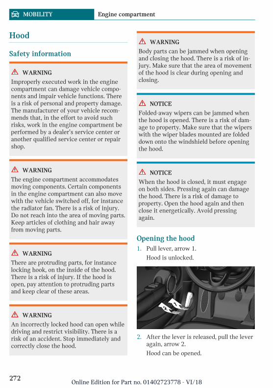
Hood
Safety information
WARNING
Improperly executed work in the enginecompartment can damage vehicle compo-nents and impair vehicle functions. Thereis a risk of personal and property damage.The manufacturer of your vehicle recom-mends that, in the effort to avoid suchrisks, work in the engine compartment beperformed by a dealer’s service center oranother qualified service center or repairshop.
WARNING
The engine compartment accommodatesmoving components. Certain componentsin the engine compartment can also movewith the vehicle switched off, for instancethe radiator fan. There is a risk of injury.Do not reach into the area of moving parts.Keep articles of clothing and hair awayfrom moving parts.
WARNING
There are protruding parts, for instancelocking hook, on the inside of the hood.There is a risk of injury. If the hood isopen, pay attention to protruding partsand keep clear of these areas.
WARNING
An incorrectly locked hood can open whiledriving and restrict visibility. There is arisk of an accident. Stop immediately andcorrectly close the hood.
WARNING
Body parts can be jammed when openingand closing the hood. There is a risk of in-jury. Make sure that the area of movementof the hood is clear during opening andclosing.
NOTICE
Folded-away wipers can be jammed whenthe hood is opened. There is a risk of dam-age to property. Make sure that the wiperswith the wiper blades mounted are foldeddown onto the windshield before openingthe hood.
NOTICE
When the hood is closed, it must engageon both sides. Pressing again can damagethe hood. There is a risk of damage toproperty. Open the hood again and thenclose it energetically. Avoid pressingagain.
Opening the hood1. Pull lever, arrow 1.
Hood is unlocked.
2. After the lever is released, pull the leveragain, arrow 2.
Hood can be opened.
Seite 272
MOBILITY Engine compartment
272Online Edition for Part no. 01402723778 - VI/18
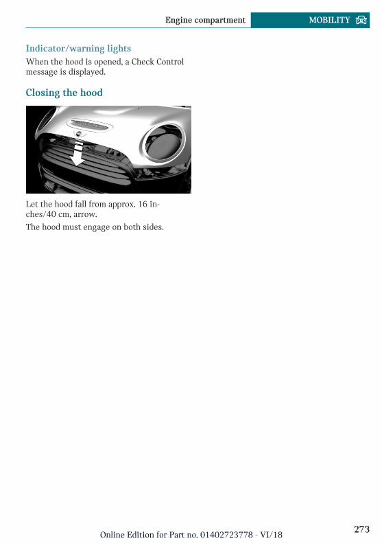
Indicator/warning lightsWhen the hood is opened, a Check Controlmessage is displayed.
Closing the hood
Let the hood fall from approx. 16 in-ches/40 cm, arrow.
The hood must engage on both sides.
Seite 273
Engine compartment MOBILITY
273Online Edition for Part no. 01402723778 - VI/18
Engine oil
Vehicle features and options
This chapter describes all standard, country-specific and optional features offered withthe series. It also describes features that arenot necessarily available in your vehicle,e. g., due to the selected options or countryversions. This also applies to safety-relatedfunctions and systems. When using thesefunctions and systems, the applicable lawsand regulations must be observed.
General information
The engine oil consumption is dependent onyour driving style and driving conditions.
Therefore, regularly check the engine oillevel after refueling by taking a detailedmeasurement.
The engine oil consumption can increase inthe following situations, for example:
– Sporty driving style.
– Break-in of the engine.
– Idling of the engine.
– With use of engine oil types that areclassified as not suitable.
Different Check Control messages appear,depending on the engine oil level.
Safety information
NOTICE
An engine oil level that is too low causesengine damage. There is a risk of damageto property. Immediately add engine oil.
NOTICE
Too much engine oil can damage the en-gine or the catalytic converter. There is arisk of damage to property. Do not add toomuch engine oil. When too much engineoil is added, have the engine oil level cor-rected by a dealer’s service center or an-other qualified service center or repairshop.
Electronic oil measurement
General informationThe electronic oil measurement has twomeasuring principles:
– Monitoring.
– Detailed measurement.
When making frequent short-distance tripsor using a dynamic driving style, for in-stance when taking curves aggressively,regularly perform a detailed measurement.
Monitoring
ConceptThe engine oil level is monitored electroni-cally while driving and can be shown on theControl Display.
If the engine oil level is outside its permis-sible operating range, a Check Control mes-sage is displayed.
A red indicator light indicates thatthe engine oil pressure is too low.
Seite 274
MOBILITY Engine oil
274Online Edition for Part no. 01402723778 - VI/18
Functional requirementsA current measured value is available afterapprox. 30 minutes of normal driving.
Displaying the engine oil levelVia the Central Information Display (CID):
1. "My MINI"
2. "Vehicle status"
3. "Engine oil level"
The engine oil level is displayed.
System limitsWhen making frequent short-distance tripsor using a dynamic driving style, it may notbe possible to calculate a measured value.In this case, the measured value for the last,sufficiently long trip is displayed.
Detailed measurement
ConceptThe engine oil level is checked when the ve-hicle is stationary and displayed via a scale.
If the engine oil level is outside its permis-sible operating range, a Check Control mes-sage is displayed.
General informationDuring the measurement, the idle speed isincreased somewhat.
Functional requirements– Vehicle is parked in a horizontal posi-
tion.
– Manual transmission: shift lever in neu-tral position, clutch and accelerator ped-als not depressed.
– Steptronic transmission: selector leverin selector lever position N or P and ac-celerator pedal not depressed.
– Engine is running and is at operatingtemperature.
Performing a detailed measurementVia the Central Information Display (CID):
1. "My MINI"
2. "Vehicle status"
3. "Engine oil level"
4. "Measure engine oil level"
5. "Start measurement"
The engine oil level is checked and dis-played via a scale.
Adding engine oil
General informationOnly add engine oil when the message isdisplayed in the instrument cluster. Thequantity to be added is indicated in themessage displayed in the instrument clus-ter.
Only add suitable types of engine oil, referto page 276.
Safely park the vehicle and switch off theignition before adding engine oil.
Take care not to add too much engine oil.
Safety information
WARNING
Operating materials, for instance oils,greases, coolants, fuels, can contain harm-ful ingredients. There is a risk of injuriesor danger to life. Follow the instructionson the containers. Avoid the contact of ar-ticles of clothing, skin or eyes with operat-ing materials. Do not refill operating mate-rials into different bottles. Store operatingmaterials out of reach of children.
Seite 275
Engine oil MOBILITY
275Online Edition for Part no. 01402723778 - VI/18
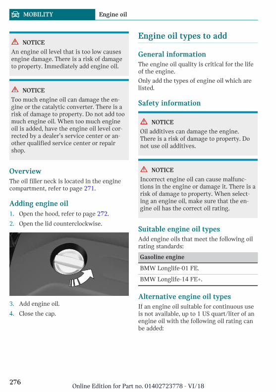
NOTICE
An engine oil level that is too low causesengine damage. There is a risk of damageto property. Immediately add engine oil.
NOTICE
Too much engine oil can damage the en-gine or the catalytic converter. There is arisk of damage to property. Do not add toomuch engine oil. When too much engineoil is added, have the engine oil level cor-rected by a dealer’s service center or an-other qualified service center or repairshop.
OverviewThe oil filler neck is located in the enginecompartment, refer to page 271.
Adding engine oil1. Open the hood, refer to page 272.
2. Open the lid counterclockwise.
3. Add engine oil.
4. Close the cap.
Engine oil types to add
General informationThe engine oil quality is critical for the lifeof the engine.
Only add the types of engine oil which arelisted.
Safety information
NOTICE
Oil additives can damage the engine.There is a risk of damage to property. Donot use oil additives.
NOTICE
Incorrect engine oil can cause malfunc-tions in the engine or damage it. There is arisk of damage to property. When select-ing an engine oil, make sure that the en-gine oil has the correct oil rating.
Suitable engine oil typesAdd engine oils that meet the following oilrating standards:
Gasoline engine
BMW Longlife-01 FE.
BMW Longlife-14 FE+.
Alternative engine oil typesIf an engine oil suitable for continuous useis not available, up to 1 US quart/liter of anengine oil with the following oil rating canbe added:
Seite 276
MOBILITY Engine oil
276Online Edition for Part no. 01402723778 - VI/18
Oil rating
API SL.
API SM.
API SN.
Viscosity gradesWhen selecting an engine oil, make surethat the engine oil belongs to one of the fol-lowing viscosity grades:
Viscosity grades
SAE 0W-20.
SAE 0W-30.
More information about suitable engine oilratings and viscosities of engine oils can berequested from a dealer’s service center oranother qualified service center or repairshop.
Engine oil change
NOTICE
Engine oil that is not changed in timelyfashion can cause increased engine wearand thus engine damage. There is a risk ofdamage to property. Do not exceed theservice data indicated in the vehicle.
The vehicle manufacturer recommends thatyou have a dealer’s service center or an-other qualified service center or repair shopchange the engine oil.
Seite 277
Engine oil MOBILITY
277Online Edition for Part no. 01402723778 - VI/18
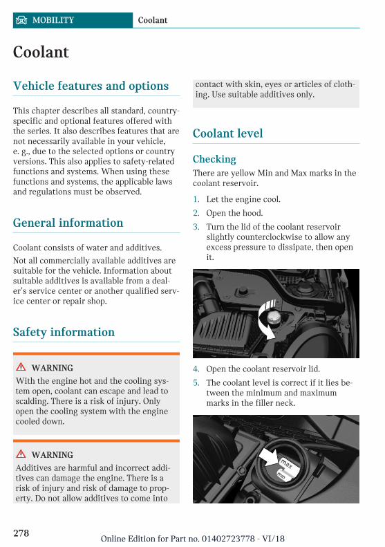
Coolant
Vehicle features and options
This chapter describes all standard, country-specific and optional features offered withthe series. It also describes features that arenot necessarily available in your vehicle,e. g., due to the selected options or countryversions. This also applies to safety-relatedfunctions and systems. When using thesefunctions and systems, the applicable lawsand regulations must be observed.
General information
Coolant consists of water and additives.
Not all commercially available additives aresuitable for the vehicle. Information aboutsuitable additives is available from a deal-er’s service center or another qualified serv-ice center or repair shop.
Safety information
WARNING
With the engine hot and the cooling sys-tem open, coolant can escape and lead toscalding. There is a risk of injury. Onlyopen the cooling system with the enginecooled down.
WARNING
Additives are harmful and incorrect addi-tives can damage the engine. There is arisk of injury and risk of damage to prop-erty. Do not allow additives to come into
contact with skin, eyes or articles of cloth-ing. Use suitable additives only.
Coolant level
CheckingThere are yellow Min and Max marks in thecoolant reservoir.
1. Let the engine cool.
2. Open the hood.
3. Turn the lid of the coolant reservoirslightly counterclockwise to allow anyexcess pressure to dissipate, then openit.
4. Open the coolant reservoir lid.
5. The coolant level is correct if it lies be-tween the minimum and maximummarks in the filler neck.
Seite 278
MOBILITY Coolant
278Online Edition for Part no. 01402723778 - VI/18
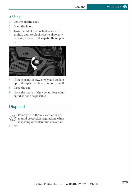
Adding1. Let the engine cool.
2. Open the hood.
3. Turn the lid of the coolant reservoirslightly counterclockwise to allow anyexcess pressure to dissipate, then openit.
4. If the coolant is low, slowly add coolantup to the specified level; do not overfill.
5. Close the cap.
6. Have the cause of the coolant loss elimi-nated as soon as possible.
Disposal
Comply with the relevant environ-mental protection regulations whendisposing of coolant and coolant ad-
ditives.
Seite 279
Coolant MOBILITY
279Online Edition for Part no. 01402723778 - VI/18
Maintenance
Vehicle features and options
This chapter describes all standard, country-specific and optional features offered withthe series. It also describes features that arenot necessarily available in your vehicle,e. g., due to the selected options or countryversions. This also applies to safety-relatedfunctions and systems. When using thesefunctions and systems, the applicable lawsand regulations must be observed.
MINI maintenance system
The maintenance system indicates requiredmaintenance measures, and thereby pro-vides support in maintaining road safetyand the operational reliability of the vehicle.
In some cases, scopes and intervals of themaintenance system may vary according tothe country version. Replacement work,spare parts, fuels and lubricants, and wearmaterials are calculated separately. Furtherinformation is available from a dealer’s serv-ice center or another qualified service cen-ter or repair shop.
Condition Based Service CBS
ConceptSensors and special algorithms take into ac-count the driving conditions of the vehicle.CBS uses these to calculate the need formaintenance.
The system makes it possible to adapt theamount of maintenance corresponding toyour user profile.
General informationInformation on service requirements, referto page 139, can be displayed on the ControlDisplay.
Service data in the remote controlInformation on the required maintenance iscontinuously stored in the remote control.The dealer’s service center can read thisdata out and suggest an optimized mainte-nance scope for the vehicle.
Therefore, hand the service advisor the re-mote control with which the vehicle wasdriven most recently.
Storage periodsStorage periods during which the vehiclebattery was disconnected are not taken intoaccount.
If this occurs, have a dealer's service centeror another qualified service center or repairshop update the time-dependent mainte-nance procedures, such as checking brakefluid and, if necessary, changing the engineoil and the microfilter/activated-charcoalfilter.
Service and Warranty Infor-mation Booklet for US modelsand Warranty and ServiceGuide Booklet for Canadianmodels
Please consult your Service and WarrantyInformation Booklet for US models andWarranty and Service Guide Booklet forCanadian models for additional informationon service requirements.
Seite 280
MOBILITY Maintenance
280Online Edition for Part no. 01402723778 - VI/18
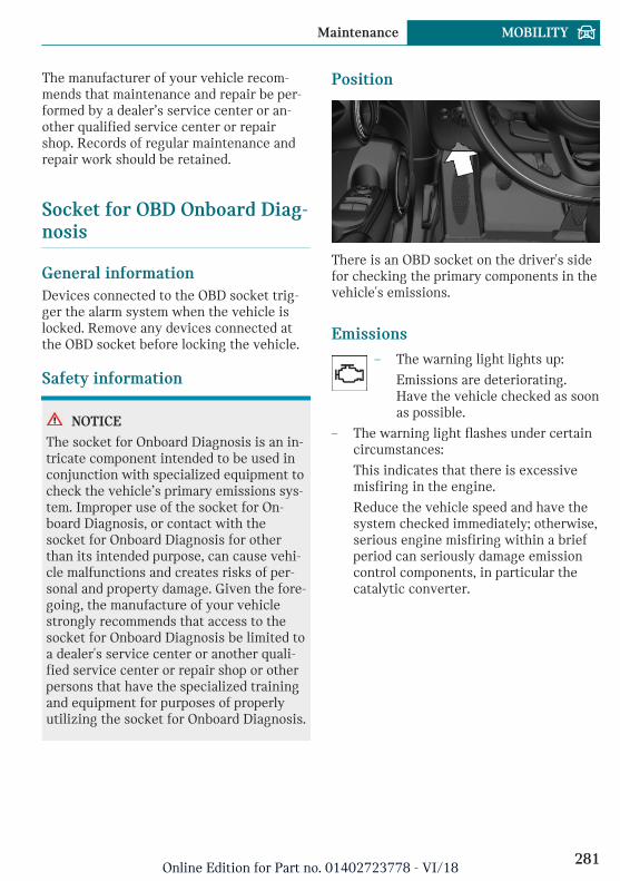
The manufacturer of your vehicle recom-mends that maintenance and repair be per-formed by a dealer’s service center or an-other qualified service center or repairshop. Records of regular maintenance andrepair work should be retained.
Socket for OBD Onboard Diag-nosis
General informationDevices connected to the OBD socket trig-ger the alarm system when the vehicle islocked. Remove any devices connected atthe OBD socket before locking the vehicle.
Safety information
NOTICE
The socket for Onboard Diagnosis is an in-tricate component intended to be used inconjunction with specialized equipment tocheck the vehicle’s primary emissions sys-tem. Improper use of the socket for On-board Diagnosis, or contact with thesocket for Onboard Diagnosis for otherthan its intended purpose, can cause vehi-cle malfunctions and creates risks of per-sonal and property damage. Given the fore-going, the manufacture of your vehiclestrongly recommends that access to thesocket for Onboard Diagnosis be limited toa dealer's service center or another quali-fied service center or repair shop or otherpersons that have the specialized trainingand equipment for purposes of properlyutilizing the socket for Onboard Diagnosis.
Position
There is an OBD socket on the driver's sidefor checking the primary components in thevehicle's emissions.
Emissions– The warning light lights up:
Emissions are deteriorating.Have the vehicle checked as soonas possible.
– The warning light flashes under certaincircumstances:
This indicates that there is excessivemisfiring in the engine.
Reduce the vehicle speed and have thesystem checked immediately; otherwise,serious engine misfiring within a briefperiod can seriously damage emissioncontrol components, in particular thecatalytic converter.
Seite 281
Maintenance MOBILITY
281Online Edition for Part no. 01402723778 - VI/18
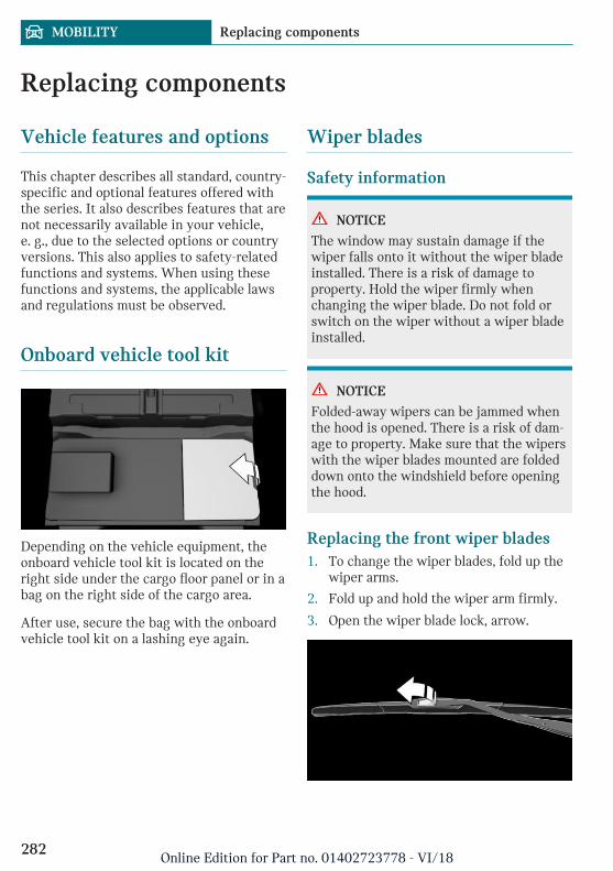
Replacing components
Vehicle features and options
This chapter describes all standard, country-specific and optional features offered withthe series. It also describes features that arenot necessarily available in your vehicle,e. g., due to the selected options or countryversions. This also applies to safety-relatedfunctions and systems. When using thesefunctions and systems, the applicable lawsand regulations must be observed.
Onboard vehicle tool kit
Depending on the vehicle equipment, theonboard vehicle tool kit is located on theright side under the cargo floor panel or in abag on the right side of the cargo area.
After use, secure the bag with the onboardvehicle tool kit on a lashing eye again.
Wiper blades
Safety information
NOTICE
The window may sustain damage if thewiper falls onto it without the wiper bladeinstalled. There is a risk of damage toproperty. Hold the wiper firmly whenchanging the wiper blade. Do not fold orswitch on the wiper without a wiper bladeinstalled.
NOTICE
Folded-away wipers can be jammed whenthe hood is opened. There is a risk of dam-age to property. Make sure that the wiperswith the wiper blades mounted are foldeddown onto the windshield before openingthe hood.
Replacing the front wiper blades1. To change the wiper blades, fold up the
wiper arms.
2. Fold up and hold the wiper arm firmly.
3. Open the wiper blade lock, arrow.
Seite 282
MOBILITY Replacing components
282Online Edition for Part no. 01402723778 - VI/18
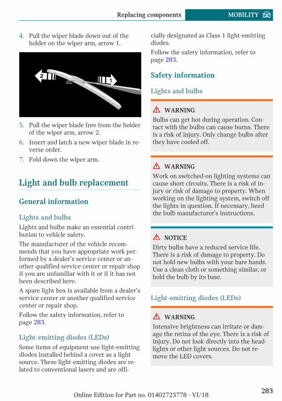
4. Pull the wiper blade down out of theholder on the wiper arm, arrow 1.
5. Pull the wiper blade free from the holderof the wiper arm, arrow 2.
6. Insert and latch a new wiper blade in re-verse order.
7. Fold down the wiper arm.
Light and bulb replacement
General information
Lights and bulbsLights and bulbs make an essential contri-bution to vehicle safety.
The manufacturer of the vehicle recom-mends that you have appropriate work per-formed by a dealer’s service center or an-other qualified service center or repair shopif you are unfamiliar with it or if it has notbeen described here.
A spare light box is available from a dealer’sservice center or another qualified servicecenter or repair shop.
Follow the safety information, refer topage 283.
Light-emitting diodes (LEDs)Some items of equipment use light-emittingdiodes installed behind a cover as a lightsource. These light-emitting diodes are re-lated to conventional lasers and are offi-
cially designated as Class 1 light-emittingdiodes.
Follow the safety information, refer topage 283.
Safety information
Lights and bulbs
WARNING
Bulbs can get hot during operation. Con-tact with the bulbs can cause burns. Thereis a risk of injury. Only change bulbs afterthey have cooled off.
WARNING
Work on switched-on lighting systems cancause short circuits. There is a risk of in-jury or risk of damage to property. Whenworking on the lighting system, switch offthe lights in question. If necessary, heedthe bulb manufacturer's instructions.
NOTICE
Dirty bulbs have a reduced service life.There is a risk of damage to property. Donot hold new bulbs with your bare hands.Use a clean cloth or something similar, orhold the bulb by its base.
Light-emitting diodes (LEDs)
WARNING
Intensive brightness can irritate or dam-age the retina of the eye. There is a risk ofinjury. Do not look directly into the head-lights or other light sources. Do not re-move the LED covers.
Seite 283
Replacing components MOBILITY
283Online Edition for Part no. 01402723778 - VI/18
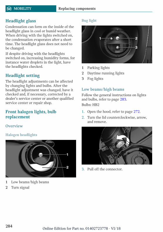
Headlight glassCondensation can form on the inside of theheadlight glass in cool or humid weather.When driving with the lights switched on,the condensation evaporates after a shorttime. The headlight glass does not need tobe changed.
If despite driving with the headlightsswitched on, increasing humidity forms, forinstance water droplets in the light, havethe headlights checked.
Headlight settingThe headlight adjustments can be affectedby changing lights and bulbs. After theheadlight adjustment was changed, have itchecked and, if necessary, corrected by adealer’s service center or another qualifiedservice center or repair shop.
Front halogen lights, bulbreplacement
Overview
Halogen headlights
1 Low beams/high beams
2 Turn signal
Bug light
1 Parking lights
2 Daytime running lights
3 Fog lights
Low beams/high beamsFollow the general instructions on lightsand bulbs, refer to page 283.
Bulbs: HB2
1. Open the hood, refer to page 272.
2. Turn the lid counterclockwise, arrow,and remove.
3. Pull off the connector.
Seite 284
MOBILITY Replacing components
284Online Edition for Part no. 01402723778 - VI/18
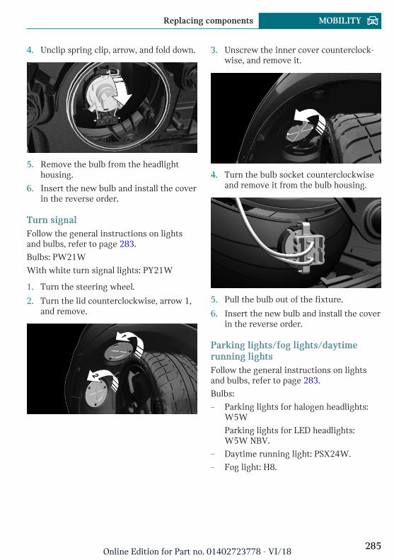
4. Unclip spring clip, arrow, and fold down.
5. Remove the bulb from the headlighthousing.
6. Insert the new bulb and install the coverin the reverse order.
Turn signalFollow the general instructions on lightsand bulbs, refer to page 283.
Bulbs: PW21W
With white turn signal lights: PY21W
1. Turn the steering wheel.
2. Turn the lid counterclockwise, arrow 1,and remove.
3. Unscrew the inner cover counterclock-wise, and remove it.
4. Turn the bulb socket counterclockwiseand remove it from the bulb housing.
5. Pull the bulb out of the fixture.
6. Insert the new bulb and install the coverin the reverse order.
Parking lights/fog lights/daytimerunning lightsFollow the general instructions on lightsand bulbs, refer to page 283.
Bulbs:
– Parking lights for halogen headlights:W5W
Parking lights for LED headlights:W5W NBV.
– Daytime running light: PSX24W.
– Fog light: H8.
Seite 285
Replacing components MOBILITY
285Online Edition for Part no. 01402723778 - VI/18
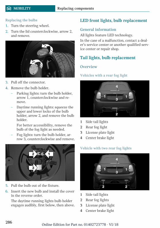
Replacing the bulbs
1. Turn the steering wheel.
2. Turn the lid counterclockwise, arrow 2,and remove.
3. Pull off the connector.
4. Remove the bulb holder.
– Parking lights: turn the bulb holder,arrow 1, counterclockwise and re-move.
– Daytime running lights: squeeze theupper and lower locks of the bulbholder, arrow 2, and remove the bulbholder.
For better accessibility, remove thebulb of the fog light as needed.
– Fog lights: turn the bulb holder, ar-row 3, counterclockwise and remove.
5. Pull the bulb out of the fixture.
6. Insert the new bulb and install the coverin the reverse order.
The daytime running lights bulb holderengages audibly, first below, then above.
LED front lights, bulb replacement
General informationAll lights feature LED technology.
In the case of a malfunction, contact a deal-er’s service center or another qualified serv-ice center or repair shop.
Tail lights, bulb replacement
Overview
Vehicles with a rear fog light
1 Side tail lights
2 Rear fog light
3 License plate light
4 Center brake light
Vehicle with two rear fog lights
1 Side tail lights
2 Rear fog lights
3 License plate light
4 Center brake light
Seite 286
MOBILITY Replacing components
286Online Edition for Part no. 01402723778 - VI/18
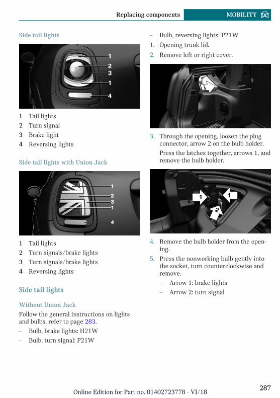
Side tail lights
1 Tail lights
2 Turn signal
3 Brake light
4 Reversing lights
Side tail lights with Union Jack
1 Tail lights
2 Turn signals/brake lights
3 Turn signals/brake lights
4 Reversing lights
Side tail lights
Without Union Jack
Follow the general instructions on lightsand bulbs, refer to page 283.
– Bulb, brake lights: H21W
– Bulb, turn signal: P21W
– Bulb, reversing lights: P21W
1. Opening trunk lid.
2. Remove left or right cover.
3. Through the opening, loosen the plugconnector, arrow 2 on the bulb holder.
Press the latches together, arrows 1, andremove the bulb holder.
4. Remove the bulb holder from the open-ing.
5. Press the nonworking bulb gently intothe socket, turn counterclockwise andremove.
– Arrow 1: brake lights
– Arrow 2: turn signal
Seite 287
Replacing components MOBILITY
287Online Edition for Part no. 01402723778 - VI/18
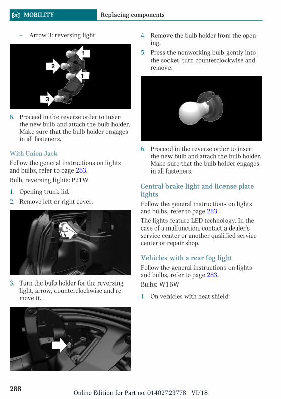
– Arrow 3: reversing light
6. Proceed in the reverse order to insertthe new bulb and attach the bulb holder.Make sure that the bulb holder engagesin all fasteners.
With Union Jack
Follow the general instructions on lightsand bulbs, refer to page 283.
Bulb, reversing lights: P21W
1. Opening trunk lid.
2. Remove left or right cover.
3. Turn the bulb holder for the reversinglight, arrow, counterclockwise and re-move it.
4. Remove the bulb holder from the open-ing.
5. Press the nonworking bulb gently intothe socket, turn counterclockwise andremove.
6. Proceed in the reverse order to insertthe new bulb and attach the bulb holder.Make sure that the bulb holder engagesin all fasteners.
Central brake light and license platelightsFollow the general instructions on lightsand bulbs, refer to page 283.
The lights feature LED technology. In thecase of a malfunction, contact a dealer’sservice center or another qualified servicecenter or repair shop.
Vehicles with a rear fog lightFollow the general instructions on lightsand bulbs, refer to page 283.
Bulbs: W16W
1. On vehicles with heat shield:
Seite 288
MOBILITY Replacing components
288Online Edition for Part no. 01402723778 - VI/18
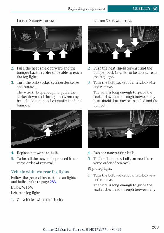
Loosen 3 screws, arrow.
2. Push the heat shield forward and thebumper back in order to be able to reachthe fog light.
3. Turn the bulb socket counterclockwiseand remove.
The wire is long enough to guide thesocket down and through between anyheat shield that may be installed and thebumper.
4. Replace nonworking bulb.
5. To install the new bulb, proceed in re-verse order of removal.
Vehicle with two rear fog lightsFollow the general instructions on lightsand bulbs, refer to page 283.
Bulbs: W16W
Left rear fog light:
1. On vehicles with heat shield:
Loosen 3 screws, arrow.
2. Push the heat shield forward and thebumper back in order to be able to reachthe fog light.
3. Turn the bulb socket counterclockwiseand remove.
The wire is long enough to guide thesocket down and through between anyheat shield that may be installed and thebumper.
4. Replace nonworking bulb.
5. To install the new bulb, proceed in re-verse order of removal.
Right fog light:
1. Turn the bulb socket counterclockwiseand remove.
The wire is long enough to guide thesocket down and through between any
Seite 289
Replacing components MOBILITY
289Online Edition for Part no. 01402723778 - VI/18
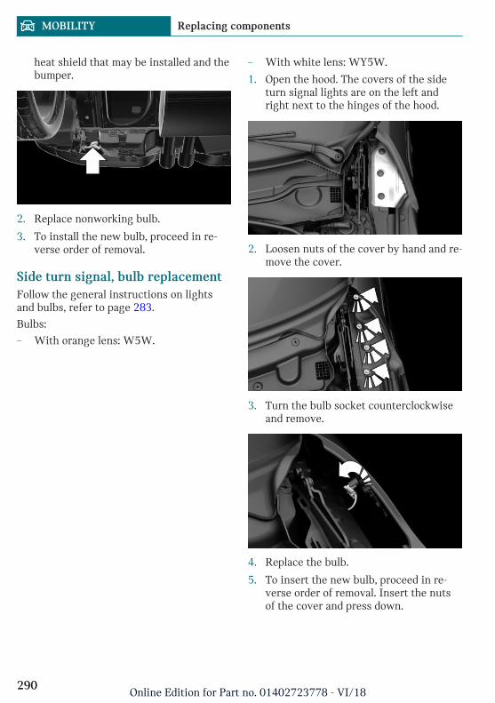
heat shield that may be installed and thebumper.
2. Replace nonworking bulb.
3. To install the new bulb, proceed in re-verse order of removal.
Side turn signal, bulb replacementFollow the general instructions on lightsand bulbs, refer to page 283.
Bulbs:
– With orange lens: W5W.
– With white lens: WY5W.
1. Open the hood. The covers of the sideturn signal lights are on the left andright next to the hinges of the hood.
2. Loosen nuts of the cover by hand and re-move the cover.
3. Turn the bulb socket counterclockwiseand remove.
4. Replace the bulb.
5. To insert the new bulb, proceed in re-verse order of removal. Insert the nutsof the cover and press down.
Seite 290
MOBILITY Replacing components
290Online Edition for Part no. 01402723778 - VI/18
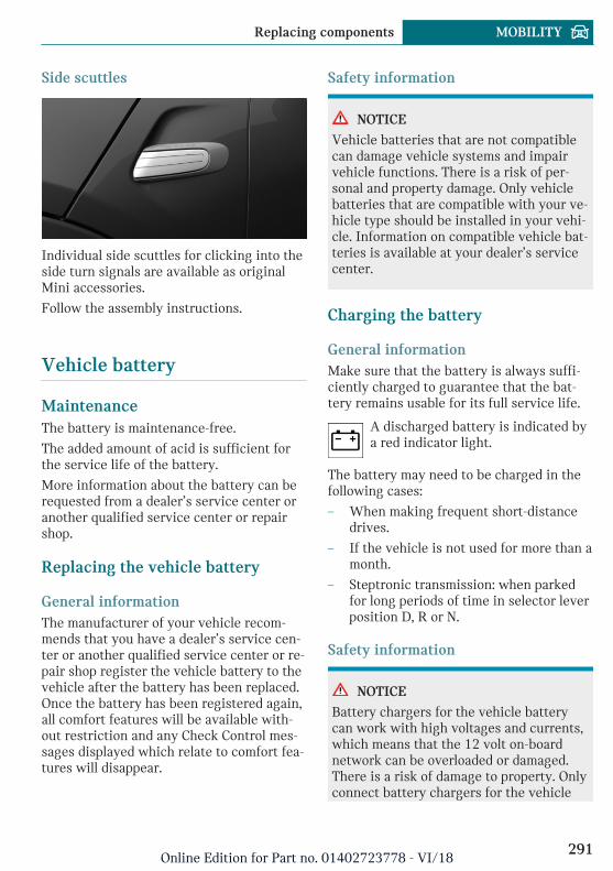
Side scuttles
Individual side scuttles for clicking into theside turn signals are available as originalMini accessories.
Follow the assembly instructions.
Vehicle battery
MaintenanceThe battery is maintenance-free.
The added amount of acid is sufficient forthe service life of the battery.
More information about the battery can berequested from a dealer’s service center oranother qualified service center or repairshop.
Replacing the vehicle battery
General informationThe manufacturer of your vehicle recom-mends that you have a dealer’s service cen-ter or another qualified service center or re-pair shop register the vehicle battery to thevehicle after the battery has been replaced.Once the battery has been registered again,all comfort features will be available with-out restriction and any Check Control mes-sages displayed which relate to comfort fea-tures will disappear.
Safety information
NOTICE
Vehicle batteries that are not compatiblecan damage vehicle systems and impairvehicle functions. There is a risk of per-sonal and property damage. Only vehiclebatteries that are compatible with your ve-hicle type should be installed in your vehi-cle. Information on compatible vehicle bat-teries is available at your dealer’s servicecenter.
Charging the battery
General informationMake sure that the battery is always suffi-ciently charged to guarantee that the bat-tery remains usable for its full service life.
A discharged battery is indicated bya red indicator light.
The battery may need to be charged in thefollowing cases:
– When making frequent short-distancedrives.
– If the vehicle is not used for more than amonth.
– Steptronic transmission: when parkedfor long periods of time in selector leverposition D, R or N.
Safety information
NOTICE
Battery chargers for the vehicle batterycan work with high voltages and currents,which means that the 12 volt on-boardnetwork can be overloaded or damaged.There is a risk of damage to property. Onlyconnect battery chargers for the vehicle
Seite 291
Replacing components MOBILITY
291Online Edition for Part no. 01402723778 - VI/18
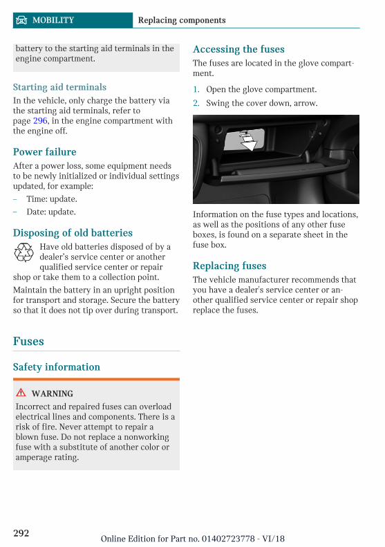
battery to the starting aid terminals in theengine compartment.
Starting aid terminalsIn the vehicle, only charge the battery viathe starting aid terminals, refer topage 296, in the engine compartment withthe engine off.
Power failureAfter a power loss, some equipment needsto be newly initialized or individual settingsupdated, for example:
– Time: update.
– Date: update.
Disposing of old batteriesHave old batteries disposed of by adealer’s service center or anotherqualified service center or repair
shop or take them to a collection point.
Maintain the battery in an upright positionfor transport and storage. Secure the batteryso that it does not tip over during transport.
Fuses
Safety information
WARNING
Incorrect and repaired fuses can overloadelectrical lines and components. There is arisk of fire. Never attempt to repair ablown fuse. Do not replace a nonworkingfuse with a substitute of another color oramperage rating.
Accessing the fusesThe fuses are located in the glove compart-ment.
1. Open the glove compartment.
2. Swing the cover down, arrow.
Information on the fuse types and locations,as well as the positions of any other fuseboxes, is found on a separate sheet in thefuse box.
Replacing fusesThe vehicle manufacturer recommends thatyou have a dealer's service center or an-other qualified service center or repair shopreplace the fuses.
Seite 292
MOBILITY Replacing components
292Online Edition for Part no. 01402723778 - VI/18
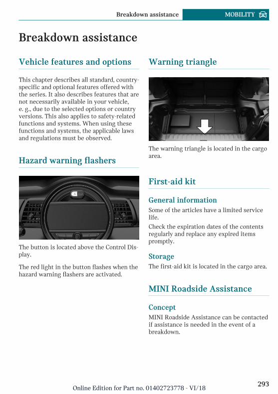
Breakdown assistance
Vehicle features and options
This chapter describes all standard, country-specific and optional features offered withthe series. It also describes features that arenot necessarily available in your vehicle,e. g., due to the selected options or countryversions. This also applies to safety-relatedfunctions and systems. When using thesefunctions and systems, the applicable lawsand regulations must be observed.
Hazard warning flashers
The button is located above the Control Dis-play.
The red light in the button flashes when thehazard warning flashers are activated.
Warning triangle
The warning triangle is located in the cargoarea.
First-aid kit
General informationSome of the articles have a limited servicelife.
Check the expiration dates of the contentsregularly and replace any expired itemspromptly.
StorageThe first-aid kit is located in the cargo area.
MINI Roadside Assistance
ConceptMINI Roadside Assistance can be contactedif assistance is needed in the event of abreakdown.
Seite 293
Breakdown assistance MOBILITY
293Online Edition for Part no. 01402723778 - VI/18
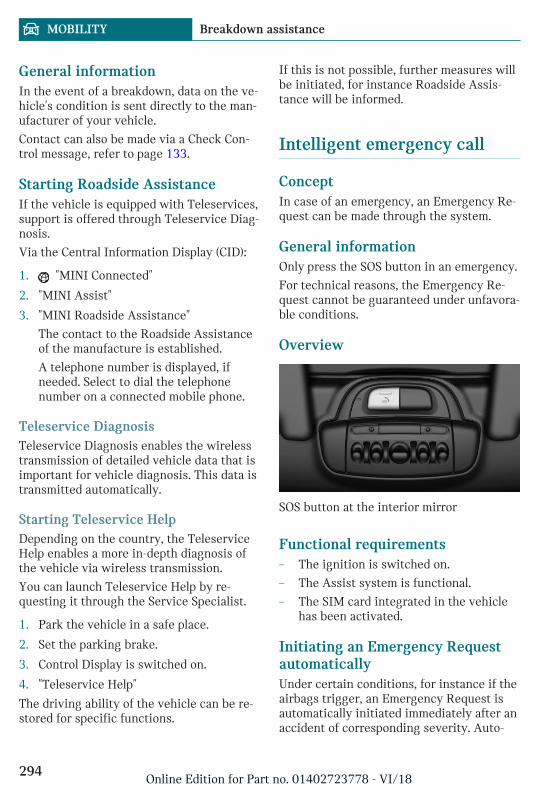
General informationIn the event of a breakdown, data on the ve-hicle's condition is sent directly to the man-ufacturer of your vehicle.
Contact can also be made via a Check Con-trol message, refer to page 133.
Starting Roadside AssistanceIf the vehicle is equipped with Teleservices,support is offered through Teleservice Diag-nosis.
Via the Central Information Display (CID):
1. "MINI Connected"
2. "MINI Assist"
3. "MINI Roadside Assistance"
The contact to the Roadside Assistanceof the manufacture is established.
A telephone number is displayed, ifneeded. Select to dial the telephonenumber on a connected mobile phone.
Teleservice DiagnosisTeleservice Diagnosis enables the wirelesstransmission of detailed vehicle data that isimportant for vehicle diagnosis. This data istransmitted automatically.
Starting Teleservice HelpDepending on the country, the TeleserviceHelp enables a more in-depth diagnosis ofthe vehicle via wireless transmission.
You can launch Teleservice Help by re-questing it through the Service Specialist.
1. Park the vehicle in a safe place.
2. Set the parking brake.
3. Control Display is switched on.
4. "Teleservice Help"
The driving ability of the vehicle can be re-stored for specific functions.
If this is not possible, further measures willbe initiated, for instance Roadside Assis-tance will be informed.
Intelligent emergency call
ConceptIn case of an emergency, an Emergency Re-quest can be made through the system.
General informationOnly press the SOS button in an emergency.
For technical reasons, the Emergency Re-quest cannot be guaranteed under unfavora-ble conditions.
Overview
SOS button at the interior mirror
Functional requirements– The ignition is switched on.
– The Assist system is functional.
– The SIM card integrated in the vehiclehas been activated.
Initiating an Emergency RequestautomaticallyUnder certain conditions, for instance if theairbags trigger, an Emergency Request isautomatically initiated immediately after anaccident of corresponding severity. Auto-
Seite 294
MOBILITY Breakdown assistance
294Online Edition for Part no. 01402723778 - VI/18
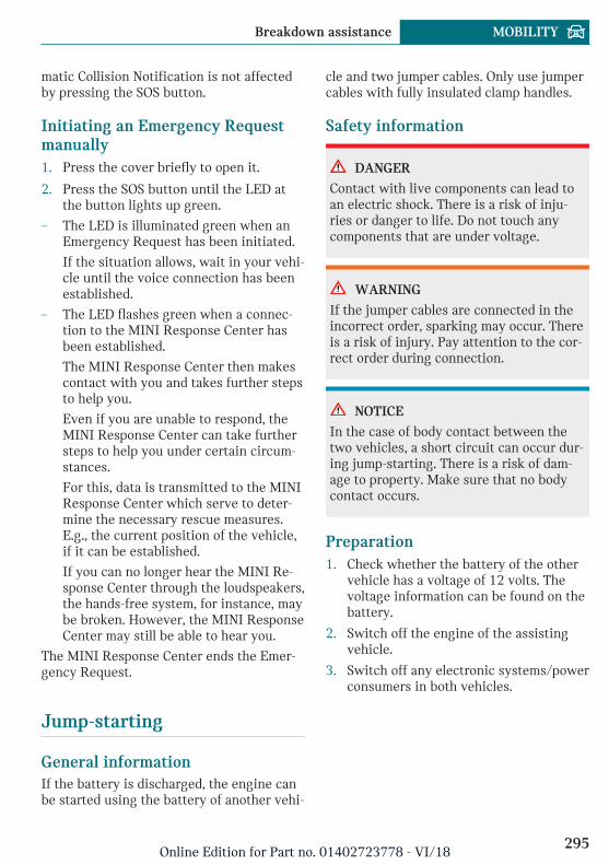
matic Collision Notification is not affectedby pressing the SOS button.
Initiating an Emergency Requestmanually1. Press the cover briefly to open it.
2. Press the SOS button until the LED atthe button lights up green.
– The LED is illuminated green when anEmergency Request has been initiated.
If the situation allows, wait in your vehi-cle until the voice connection has beenestablished.
– The LED flashes green when a connec-tion to the MINI Response Center hasbeen established.
The MINI Response Center then makescontact with you and takes further stepsto help you.
Even if you are unable to respond, theMINI Response Center can take furthersteps to help you under certain circum-stances.
For this, data is transmitted to the MINIResponse Center which serve to deter-mine the necessary rescue measures.E.g., the current position of the vehicle,if it can be established.
If you can no longer hear the MINI Re-sponse Center through the loudspeakers,the hands-free system, for instance, maybe broken. However, the MINI ResponseCenter may still be able to hear you.
The MINI Response Center ends the Emer-gency Request.
Jump-starting
General informationIf the battery is discharged, the engine canbe started using the battery of another vehi-
cle and two jumper cables. Only use jumpercables with fully insulated clamp handles.
Safety information
DANGER
Contact with live components can lead toan electric shock. There is a risk of inju-ries or danger to life. Do not touch anycomponents that are under voltage.
WARNING
If the jumper cables are connected in theincorrect order, sparking may occur. Thereis a risk of injury. Pay attention to the cor-rect order during connection.
NOTICE
In the case of body contact between thetwo vehicles, a short circuit can occur dur-ing jump-starting. There is a risk of dam-age to property. Make sure that no bodycontact occurs.
Preparation1. Check whether the battery of the other
vehicle has a voltage of 12 volts. Thevoltage information can be found on thebattery.
2. Switch off the engine of the assistingvehicle.
3. Switch off any electronic systems/powerconsumers in both vehicles.
Seite 295
Breakdown assistance MOBILITY
295Online Edition for Part no. 01402723778 - VI/18
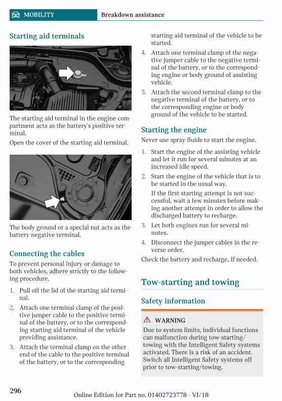
Starting aid terminals
The starting aid terminal in the engine com-partment acts as the battery's positive ter-minal.
Open the cover of the starting aid terminal.
The body ground or a special nut acts as thebattery negative terminal.
Connecting the cablesTo prevent personal injury or damage toboth vehicles, adhere strictly to the follow-ing procedure.
1. Pull off the lid of the starting aid termi-nal.
2. Attach one terminal clamp of the posi-tive jumper cable to the positive termi-nal of the battery, or to the correspond-ing starting aid terminal of the vehicleproviding assistance.
3. Attach the terminal clamp on the otherend of the cable to the positive terminalof the battery, or to the corresponding
starting aid terminal of the vehicle to bestarted.
4. Attach one terminal clamp of the nega-tive jumper cable to the negative termi-nal of the battery, or to the correspond-ing engine or body ground of assistingvehicle.
5. Attach the second terminal clamp to thenegative terminal of the battery, or tothe corresponding engine or bodyground of the vehicle to be started.
Starting the engineNever use spray fluids to start the engine.
1. Start the engine of the assisting vehicleand let it run for several minutes at anincreased idle speed.
2. Start the engine of the vehicle that is tobe started in the usual way.
If the first starting attempt is not suc-cessful, wait a few minutes before mak-ing another attempt in order to allow thedischarged battery to recharge.
3. Let both engines run for several mi-nutes.
4. Disconnect the jumper cables in the re-verse order.
Check the battery and recharge, if needed.
Tow-starting and towing
Safety information
WARNING
Due to system limits, individual functionscan malfunction during tow-starting/towing with the Intelligent Safety systemsactivated. There is a risk of an accident.Switch all Intelligent Safety systems offprior to tow-starting/towing.
Seite 296
MOBILITY Breakdown assistance
296Online Edition for Part no. 01402723778 - VI/18
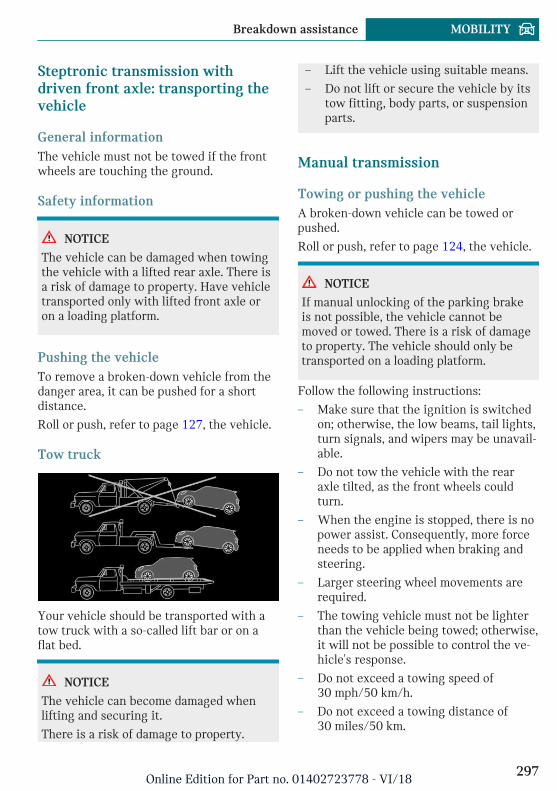
Steptronic transmission withdriven front axle: transporting thevehicle
General informationThe vehicle must not be towed if the frontwheels are touching the ground.
Safety information
NOTICE
The vehicle can be damaged when towingthe vehicle with a lifted rear axle. There isa risk of damage to property. Have vehicletransported only with lifted front axle oron a loading platform.
Pushing the vehicleTo remove a broken-down vehicle from thedanger area, it can be pushed for a shortdistance.
Roll or push, refer to page 127, the vehicle.
Tow truck
Your vehicle should be transported with atow truck with a so-called lift bar or on aflat bed.
NOTICE
The vehicle can become damaged whenlifting and securing it.
There is a risk of damage to property.
– Lift the vehicle using suitable means.
– Do not lift or secure the vehicle by itstow fitting, body parts, or suspensionparts.
Manual transmission
Towing or pushing the vehicleA broken-down vehicle can be towed orpushed.
Roll or push, refer to page 124, the vehicle.
NOTICE
If manual unlocking of the parking brakeis not possible, the vehicle cannot bemoved or towed. There is a risk of damageto property. The vehicle should only betransported on a loading platform.
Follow the following instructions:
– Make sure that the ignition is switchedon; otherwise, the low beams, tail lights,turn signals, and wipers may be unavail-able.
– Do not tow the vehicle with the rearaxle tilted, as the front wheels couldturn.
– When the engine is stopped, there is nopower assist. Consequently, more forceneeds to be applied when braking andsteering.
– Larger steering wheel movements arerequired.
– The towing vehicle must not be lighterthan the vehicle being towed; otherwise,it will not be possible to control the ve-hicle's response.
– Do not exceed a towing speed of30 mph/50 km/h.
– Do not exceed a towing distance of30 miles/50 km.
Seite 297
Breakdown assistance MOBILITY
297Online Edition for Part no. 01402723778 - VI/18
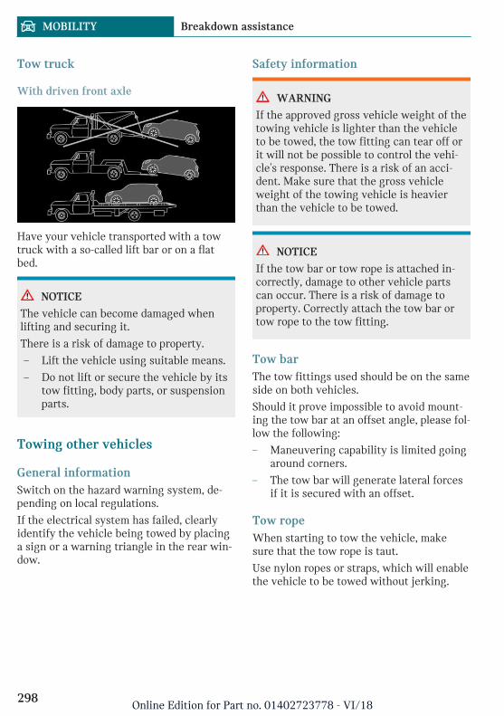
Tow truck
With driven front axle
Have your vehicle transported with a towtruck with a so-called lift bar or on a flatbed.
NOTICE
The vehicle can become damaged whenlifting and securing it.
There is a risk of damage to property.
– Lift the vehicle using suitable means.
– Do not lift or secure the vehicle by itstow fitting, body parts, or suspensionparts.
Towing other vehicles
General informationSwitch on the hazard warning system, de-pending on local regulations.
If the electrical system has failed, clearlyidentify the vehicle being towed by placinga sign or a warning triangle in the rear win-dow.
Safety information
WARNING
If the approved gross vehicle weight of thetowing vehicle is lighter than the vehicleto be towed, the tow fitting can tear off orit will not be possible to control the vehi-cle's response. There is a risk of an acci-dent. Make sure that the gross vehicleweight of the towing vehicle is heavierthan the vehicle to be towed.
NOTICE
If the tow bar or tow rope is attached in-correctly, damage to other vehicle partscan occur. There is a risk of damage toproperty. Correctly attach the tow bar ortow rope to the tow fitting.
Tow barThe tow fittings used should be on the sameside on both vehicles.
Should it prove impossible to avoid mount-ing the tow bar at an offset angle, please fol-low the following:
– Maneuvering capability is limited goingaround corners.
– The tow bar will generate lateral forcesif it is secured with an offset.
Tow ropeWhen starting to tow the vehicle, makesure that the tow rope is taut.
Use nylon ropes or straps, which will enablethe vehicle to be towed without jerking.
Seite 298
MOBILITY Breakdown assistance
298Online Edition for Part no. 01402723778 - VI/18
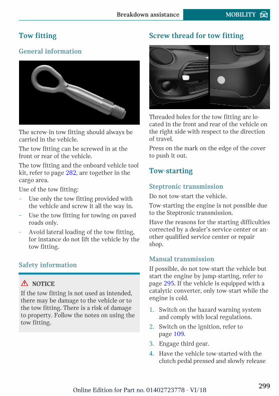
Tow fitting
General information
The screw-in tow fitting should always becarried in the vehicle.
The tow fitting can be screwed in at thefront or rear of the vehicle.
The tow fitting and the onboard vehicle toolkit, refer to page 282, are together in thecargo area.
Use of the tow fitting:
– Use only the tow fitting provided withthe vehicle and screw it all the way in.
– Use the tow fitting for towing on pavedroads only.
– Avoid lateral loading of the tow fitting,for instance do not lift the vehicle by thetow fitting.
Safety information
NOTICE
If the tow fitting is not used as intended,there may be damage to the vehicle or tothe tow fitting. There is a risk of damageto property. Follow the notes on using thetow fitting.
Screw thread for tow fitting
Threaded holes for the tow fitting are lo-cated in the front and rear of the vehicle onthe right side with respect to the directionof travel.
Press on the mark on the edge of the coverto push it out.
Tow-starting
Steptronic transmissionDo not tow-start the vehicle.
Tow-starting the engine is not possible dueto the Steptronic transmission.
Have the reasons for the starting difficultiescorrected by a dealer’s service center or an-other qualified service center or repairshop.
Manual transmissionIf possible, do not tow-start the vehicle butstart the engine by jump-starting, refer topage 295. If the vehicle is equipped with acatalytic converter, only tow-start while theengine is cold.
1. Switch on the hazard warning systemand comply with local regulations.
2. Switch on the ignition, refer topage 109.
3. Engage third gear.
4. Have the vehicle tow-started with theclutch pedal pressed and slowly release
Seite 299
Breakdown assistance MOBILITY
299Online Edition for Part no. 01402723778 - VI/18
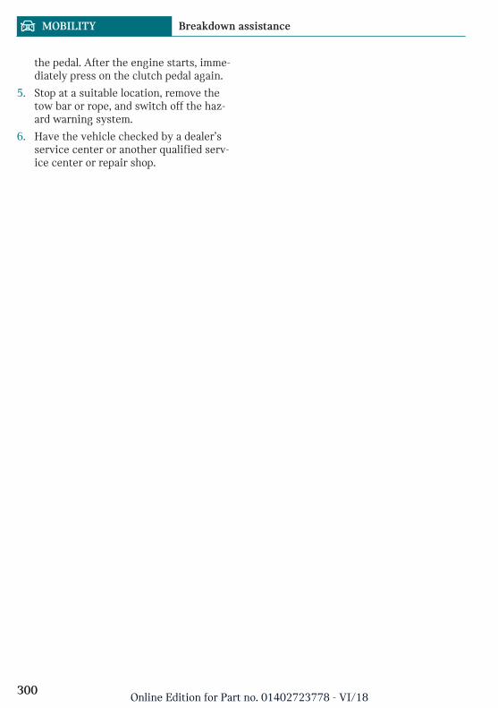
the pedal. After the engine starts, imme-diately press on the clutch pedal again.
5. Stop at a suitable location, remove thetow bar or rope, and switch off the haz-ard warning system.
6. Have the vehicle checked by a dealer’sservice center or another qualified serv-ice center or repair shop.
Seite 300
MOBILITY Breakdown assistance
300Online Edition for Part no. 01402723778 - VI/18
Care
Vehicle features and options
This chapter describes all standard, country-specific and optional features offered withthe series. It also describes features that arenot necessarily available in your vehicle,e. g., due to the selected options or countryversions. This also applies to safety-relatedfunctions and systems. When using thesefunctions and systems, the applicable lawsand regulations must be observed.
Washing the vehicle
General informationRegularly remove foreign objects such asleaves in the area below the windshieldwhen the hood is raised.
Wash your vehicle frequently, particularlyin winter. Intense soiling and road salt candamage the vehicle.
Steam jets or high-pressurewashers
Safety information
NOTICE
When cleaning with high-pressure wash-ers, components can be damaged due tothe pressure or temperatures being toohigh. There is a risk of damage to property.Maintain sufficient distance and do notspray too long continuously. Follow theoperating instructions for the high-pres-sure washer.
Distances and temperature– Maximum temperature: 140 ℉/60 ℃.
– Minimum distance from sensors, cam-eras, seals: 12 inches/30 cm.
Automatic vehicle washes
Safety information
NOTICE
Water can penetrate in the windshieldarea due to high-pressure washers. Thereis a risk of damage to property. Avoidhigh-pressure washers.
NOTICE
Improper use of automatic vehicle washescan cause damage to the vehicle. There isa risk of damage to property. Follow thefollowing instructions:
– Give preference to cloth vehiclewashes or those that use soft brushesin order to avoid paint damage.
– Avoid vehicle washes with guide railshigher than 4 in/10 cm to avoid dam-age to the chassis.
– Observe the tire width of the guiderail to avoid damage to tires and rims.
– Fold in exterior mirrors to avoid dam-age to the exterior mirrors.
– Unscrew the rod antenna to avoid therod antenna breaking off.
– Deactivate the wiper and, if neces-sary, rain sensor to avoid damage tothe wiper system.
Seite 301
Care MOBILITY
301Online Edition for Part no. 01402723778 - VI/18
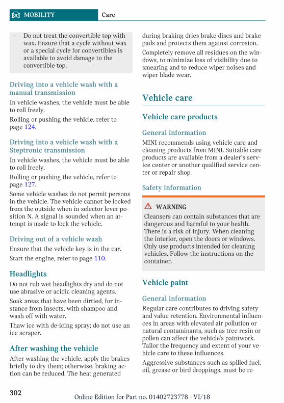
– Do not treat the convertible top withwax. Ensure that a cycle without waxor a special cycle for convertibles isavailable to avoid damage to theconvertible top.
Driving into a vehicle wash with amanual transmissionIn vehicle washes, the vehicle must be ableto roll freely.
Rolling or pushing the vehicle, refer topage 124.
Driving into a vehicle wash with aSteptronic transmissionIn vehicle washes, the vehicle must be ableto roll freely.
Rolling or pushing the vehicle, refer topage 127.
Some vehicle washes do not permit personsin the vehicle. The vehicle cannot be lockedfrom the outside when in selector lever po-sition N. A signal is sounded when an at-tempt is made to lock the vehicle.
Driving out of a vehicle washEnsure that the vehicle key is in the car.
Start the engine, refer to page 110.
HeadlightsDo not rub wet headlights dry and do notuse abrasive or acidic cleaning agents.
Soak areas that have been dirtied, for in-stance from insects, with shampoo andwash off with water.
Thaw ice with de-icing spray; do not use anice scraper.
After washing the vehicleAfter washing the vehicle, apply the brakesbriefly to dry them; otherwise, braking ac-tion can be reduced. The heat generated
during braking dries brake discs and brakepads and protects them against corrosion.
Completely remove all residues on the win-dows, to minimize loss of visibility due tosmearing and to reduce wiper noises andwiper blade wear.
Vehicle care
Vehicle care products
General informationMINI recommends using vehicle care andcleaning products from MINI. Suitable careproducts are available from a dealer’s serv-ice center or another qualified service cen-ter or repair shop.
Safety information
WARNING
Cleansers can contain substances that aredangerous and harmful to your health.There is a risk of injury. When cleaningthe interior, open the doors or windows.Only use products intended for cleaningvehicles. Follow the instructions on thecontainer.
Vehicle paint
General informationRegular care contributes to driving safetyand value retention. Environmental influen-ces in areas with elevated air pollution ornatural contaminants, such as tree resin orpollen can affect the vehicle's paintwork.Tailor the frequency and extent of your ve-hicle care to these influences.
Aggressive substances such as spilled fuel,oil, grease or bird droppings, must be re-
Seite 302
MOBILITY Care
302Online Edition for Part no. 01402723778 - VI/18
moved immediately to prevent the finishfrom being altered or discolored.
Safety information
WARNING
Improperly performed work on the vehiclepaint can lead to a failure or malfunctionof the radar sensors and thereby result in asafety risk. There is a risk of accidents orrisk of damage to property. Have paint-work or paintwork repairs on bumpers ofvehicles with radar sensors performed by adealer’s service center or another qualifiedservice center or repair shop only.
Matte finishOnly use cleaning and care products suita-ble for vehicles with matte finish.
Caring for the convertible top
General informationThe appearance and life of the convertibletop depend on correct care and operation.
Follow the following instructions:
– Clean roofliner with a microfiber cloth.Dampen cloth lightly with water.
– Do not soak the roofliner.
– To avoid water stains, spots of mold, andchafe marks, do not keep the convertibletop enclosed in its case for a long periodof time. Do not fold up the convertibletop or stow it in its case when it is wetor icy.
– Remove any water stains that have ap-peared on the roofliner using a micro-fiber cloth and an interior cleaner.
– When the vehicle is parked in enclosedareas for lengthy periods, ensure thatthe area is well ventilated.
– Park the vehicle in the shade to protectit from intensive solar radiation so thatcolor, rubber, and fabric are not af-fected.
– Remove bird droppings immediately astheir corrosive effect will otherwise at-tack the convertible top and damage therubber seals.
– Hard to remove tree sap or bird drop-pings can be removed from theconvertible top with special tree sap re-mover and a soft brush.
Safety information
NOTICE
Spot remover, paint thinner, solvents, gas-oline or similar can damage theconvertible top or the rubber coating.There is a risk of damage to property. Toremove spots on the convertible top, useonly suitable cleaning agents, for instancespecial convertible top cleaning agent.
Cleaning the convertible topTo remove heavy soiling, especially for lightcolored convertible tops, use a specialconvertible top cleaner.
Proceed as follows when cleaning:
1. Spray the convertible top with theconvertible top cleaner. Follow the man-ufacturer's instructions.
2. Make the convertible top cleaner foamup using a well saturated sponge, mov-ing it in circular motions.
3. Finish washing the vehicle in the vehi-cle wash or rinse with ample amounts ofwater. Follow notes regarding automaticwashing systems or vehicle washes.
Treat the convertible top with an impreg-nating agent after it has been washed threeto five times.
Seite 303
Care MOBILITY
303Online Edition for Part no. 01402723778 - VI/18
Suitable cleaning agents and care productsare available from a dealer’s service centeror another qualified service center or repairshop.
Leather careRemove dust from the leather regularly, us-ing a cloth or vacuum cleaner.
Otherwise, particles of dust and road grimechafe in pores and folds, and lead to in-creased wear and premature degradation ofthe leather surface.
To guard against discoloration, such as fromclothing, clean leather and provide leathercare roughly every two months.
Clean light-colored leather more frequentlybecause soiling on such surfaces is substan-tially more visible.
Use leather care products; otherwise, dirtand grease will gradually break down theprotective layer of the leather surface.
Upholstery material care
General informationVacuum the upholstery regularly with avacuum cleaner.
If upholstery is very dirty, for instance withbeverage stains, use a soft sponge or micro-fiber cloth with a suitable interior cleaner.
Clean the upholstery down to the seams us-ing large sweeping motions. Avoid rubbingthe material vigorously.
Safety information
NOTICE
Open Velcro® fasteners on articles ofclothing can damage the seat covers.There is a risk of damage to property. En-sure that any Velcro® fasteners are closed.
Caring for special components
Light-alloy wheelsWhen cleaning the vehicle, use only neutralwheel cleaners having a pH value from 5 to9. Do not use abrasive cleaning agents orsteam jets above 140 ℉/60 ℃. Follow themanufacturer's instructions.
Aggressive, acidic or alkaline cleaningagents can destroy the protective layer ofadjacent components, such as the brakedisc.
After cleaning, apply the brakes briefly todry them. The heat generated during brak-ing dries brake discs and brake pads andprotects them against corrosion.
Chrome surfacesCarefully clean components such as the ra-diator grille or door handles with an amplesupply of water, possibly with shampooadded, particularly when they have been ex-posed to road salt.
Rubber componentsEnvironmental influences can cause surfacesoiling of rubber parts and a loss of gloss.Use only water and suitable cleaning agentsfor cleaning.
Treat especially worn rubber parts with rub-ber care agents at regular intervals. Whencleaning rubber seals, do not use any sili-con-containing vehicle care products in or-der to avoid damage or noises.
Fine wood partsClean fine wood facing and fine wood com-ponents only with a moist rag. Then drywith a soft cloth.
Seite 304
MOBILITY Care
304Online Edition for Part no. 01402723778 - VI/18
Plastic components
NOTICE
Cleansers that contain alcohol or solvents,such as lacquer thinners, heavy-dutygrease removers, fuel, or such, can damageplastic parts. There is a risk of damage toproperty. Clean with a microfiber cloth.Dampen cloth lightly with water.
Plastic components are e.g.:
– Imitation leather surfaces.
– Light lenses.
– Instrument cluster cover.
– Matt black spray-coated components.
– Painted parts in the car's interior.
Clean with a microfiber cloth.
Dampen cloth lightly with water.
Safety belts
WARNING
Chemical cleansers can destroy the safetybelt webbing. Missing protective effect ofthe safety belts. There is a risk of injuriesor danger to life. Use only a mild soapy sol-ution for cleaning the safety belts.
Dirty belt straps impede the reeling actionand thus have a negative impact on safety.
Use only a mild soapy solution, with thesafety belts clipped into their buckles.
Safety belts should only be allowed to re-tract if they are dry.
Carpets and floor mats
WARNING
Objects in the driver's floor area can limitthe pedal distance or block a depressedpedal. There is a risk of an accident. Stowobjects in the vehicle such that they aresecured and cannot enter into the driver'sfloor area. Use floor mats that are suitablefor the vehicle and can be safely attachedto the floor. Do not use loose floor matsand do not layer several floor mats. Makesure that there is sufficient clearance forthe pedals. Ensure that the floor mats aresecurely fastened again after they were re-moved, for instance for cleaning.
Floor mats can be removed from the car'sinterior for cleaning.
If the floor carpets are very dirty, clean witha microfiber cloth and water or a textilecleaner. To prevent matting of the carpet,rub back and forth in the direction of travelonly.
Sensor/camera lensesTo clean sensors and camera lenses, use acloth moistened with a small amount ofglass detergent.
Displays/Screens/Projection lenses
NOTICE
Chemical cleansers, moisture or fluids ofany kind can damage the surface of dis-plays and screens. There is a risk of dam-age to property. Clean with a clean, anti-static microfiber cloth.
Seite 305
Care MOBILITY
305Online Edition for Part no. 01402723778 - VI/18
NOTICE
The surface of displays can be damagedwith improper cleaning. There is a risk ofdamage to property. Avoid pressure that istoo high and do not use any scratchingmaterials.
Clean with a clean, antistatic microfibercloth.
For stubborn soiling on the projection lensof the Head-up Display, dampen the micro-fiber cloth with alcohol. Projection lens, re-fer to page 148.
Long-term vehicle storageWhen the vehicle is shut down for longerthan three months, special measures mustbe taken. Further information is availablefrom a dealer’s service center or anotherqualified service center or repair shop.
Seite 306
MOBILITY Care
306Online Edition for Part no. 01402723778 - VI/18

Seite 307
Care MOBILITY
307Online Edition for Part no. 01402723778 - VI/18

308
Online Edition for Part no. 01402723778 - VI/18
REFERENCE
Technical data ......................................................................................... 310Appendix .................................................................................................. 313Everything from A to Z ........................................................................ 314
309Online Edition for Part no. 01402723778 - VI/18
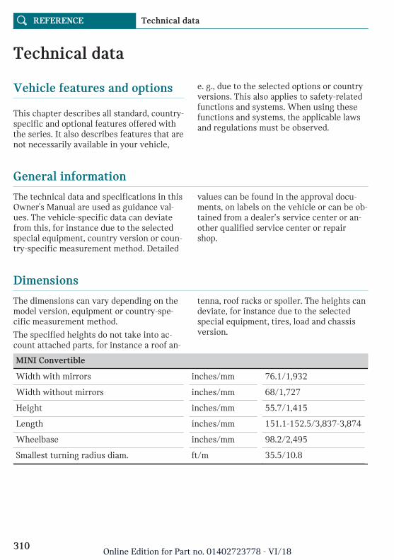
Technical data
Vehicle features and options
This chapter describes all standard, country-specific and optional features offered withthe series. It also describes features that arenot necessarily available in your vehicle,
e. g., due to the selected options or countryversions. This also applies to safety-relatedfunctions and systems. When using thesefunctions and systems, the applicable lawsand regulations must be observed.
General information
The technical data and specifications in thisOwner's Manual are used as guidance val-ues. The vehicle-specific data can deviatefrom this, for instance due to the selectedspecial equipment, country version or coun-try-specific measurement method. Detailed
values can be found in the approval docu-ments, on labels on the vehicle or can be ob-tained from a dealer’s service center or an-other qualified service center or repairshop.
Dimensions
The dimensions can vary depending on themodel version, equipment or country-spe-cific measurement method.
The specified heights do not take into ac-count attached parts, for instance a roof an-
tenna, roof racks or spoiler. The heights candeviate, for instance due to the selectedspecial equipment, tires, load and chassisversion.
MINI Convertible
Width with mirrors inches/mm 76.1/1,932
Width without mirrors inches/mm 68/1,727
Height inches/mm 55.7/1,415
Length inches/mm 151.1-152.5/3,837-3,874
Wheelbase inches/mm 98.2/2,495
Smallest turning radius diam. ft/m 35.5/10.8
Seite 310
REFERENCE Technical data
310Online Edition for Part no. 01402723778 - VI/18
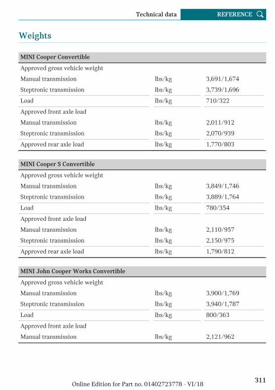
Weights
MINI Cooper Convertible
Approved gross vehicle weight
Manual transmission lbs/kg 3,691/1,674
Steptronic transmission lbs/kg 3,739/1,696
Load lbs/kg 710/322
Approved front axle load
Manual transmission lbs/kg 2,011/912
Steptronic transmission lbs/kg 2,070/939
Approved rear axle load lbs/kg 1,770/803
MINI Cooper S Convertible
Approved gross vehicle weight
Manual transmission lbs/kg 3,849/1,746
Steptronic transmission lbs/kg 3,889/1,764
Load lbs/kg 780/354
Approved front axle load
Manual transmission lbs/kg 2,110/957
Steptronic transmission lbs/kg 2,150/975
Approved rear axle load lbs/kg 1,790/812
MINI John Cooper Works Convertible
Approved gross vehicle weight
Manual transmission lbs/kg 3,900/1,769
Steptronic transmission lbs/kg 3,940/1,787
Load lbs/kg 800/363
Approved front axle load
Manual transmission lbs/kg 2,121/962
Seite 311
Technical data REFERENCE
311Online Edition for Part no. 01402723778 - VI/18
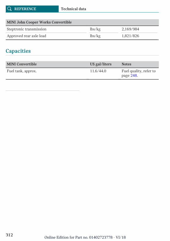
MINI John Cooper Works Convertible
Steptronic transmission lbs/kg 2,169/984
Approved rear axle load lbs/kg 1,821/826
Capacities
MINI Convertible US gal/liters Notes
Fuel tank, approx. 11.6/44.0 Fuel quality, refer topage 248.
Seite 312
REFERENCE Technical data
312Online Edition for Part no. 01402723778 - VI/18
Appendix
Any updates to the Owner's Manual of thevehicle are listed here.
Updates made after the editorial deadline
These chapters of the printed Owner'sManual contain updates made after the edi-torial deadline:
– Information: Data storage, refer topage 12.
Seite 313
Appendix REFERENCE
313Online Edition for Part no. 01402723778 - VI/18
Everything from A to Z
Index
A
ABS, Antilock Brake System 180 Acceleration Assistant, see Launch Con-
trol 131 Accessories and parts 10 ACC, see Camera-based cruise control 185 Activated-charcoal filter 211 Activation times, parked-car ventila-
tion 212 Active Cruise Control, see Camera-based
cruise control 185 Active Guard, see Intelligent Safety 170 Adaptive brake lights, see Brake force dis-
play 177 Adaptive chassis 182 Additives, engine oil types 276 Adjustments, steering wheel 103 After washing vehicle 302 Airbags 158 Airbags, indicator and warning light 160 Air circulation, see Recirculated-air
mode 206, 210 Air conditioner 205 Air conditioning 206, 209 Air, dehumidifying, see Air condition-
ing 206, 209 Air distribution, manual 207, 211 Air flow, air conditioner 207 Air flow, automatic climate control 210 Air pressure, tires 250 Air vents, see Ventilation 211 Alarm system 83 Alarm triggering 83 Alarm, unintentional 84 Alertness assistant 178 All around the interior mirror 41 All-season tires, see Winter tires 258 Always Open Timer, Control Display 150
Always Open Timer, Onboard Com-puter 144
Antifreeze, washer fluid 122 Antilock Brake System, ABS 180 Anti-slip control, see DSC 180 Anti-theft protection, lug bolts 266 Approach control warning with city light
braking function 171 Approved axle load 311 Apps, see Owner's Handbook for Naviga-
tion, Entertainment, Communication 8 Arrival time 145 Ash tray 219 Assistance when driving off 183 AUTO intensity 210 Automatic climate control 208 Automatic Curb Monitor 102 Automatic deactivation, front-seat passen-
ger airbags 160 Automatic headlight control 153 Automatic locking 82 Automatic transmission with Step-
tronic 124 Automatic unlocking 83 Automatic vehicle wash 301 AUTO program, automatic climate con-
trol 209 AUTO program, intensity 210 Auto Start/Stop function 112 Auto washing 301 Average fuel consumption 144 Average speed 144 Axle loads, weights 311
B
Backrest curvature, see Lumbar support 96 Backrest, seats 95 Band-aids, see First-aid kit 293 Battery replacement, vehicle battery 291
Seite 314
REFERENCE Everything from A to Z
314Online Edition for Part no. 01402723778 - VI/18
Battery, vehicle 291 Being towed, see Tow-starting and tow-
ing 296 Belts, safety belts 97 Beverage holder, cup holder 223 Bluetooth connection 59 Bonus range, GREEN Mode 240 Bottle holder, see Cup holder 223 Brake assistant 180 Brake discs, break-in 232 Brake force display 177 Brake lights, brake force display 177 Brake pads, break-in 232 Braking, information 234 Breakdown assistance 293 Break-in 232 Brightness of Control Display 56 Bug light 284 Bulb replacement 283 Bulb replacement, front 284, 286 Bulb replacement, rear 286 Bulb replacement, side 290 Bulbs and lights 283 Button, SOS 294 Button, Start/Stop 109 Bypassing, see Jump-starting 295
C
Calendar, see Owner's Handbook for Naviga-tion, Entertainment, Communication 8
California Proposition 65 Warning 10 Camera-based assistance systems, see Intel-
ligent Safety 170 Camera-based cruise control 185 Camera lenses, care 305 Camera, rearview camera 197 Can holder, see Cup holder 223 Care, displays 305 Care, vehicle 302 Care, washing the vehicle 301 Cargo area 224 Cargo area, enlarging 226 Cargo area, loading 225 Cargo area partition 227 Cargo area, storage compartments 226
Cargo, stowing and securing 225 Cargo straps 226 Carpet, care 305 Catalytic converter, see Hot exhaust gas
system 233 CBS Condition Based Service 280 Center armrest 222 Center console 40 Central Information Display (CID) 42 Central Information Display (CID) operating
concept 42 Central instrument cluster, LED ring 147 Central locking system, unlocking, from in-
side 76 Central screen, see Control Display 44 Changes, technical, see For Your Own
Safety 9 Changing parts 282 Changing wheels 264 Changing wheels/tires 257 Chassis number, see Vehicle identification
number 15 Check Control 133 Checking the oil level electronically 274 Children, seating position 105 Children, transporting safely 105 Child restraint system 105 Child restraint system LATCH 107 Child restraint systems, mounting 106 Child seat, mounting 106 Child seats 105 Chrome parts, care 304 Cigarette lighter 219 Cleaning, displays 305 Climate control 205, 208 Coasting 241 Coasting with engine decoupled, coast-
ing 241 Coasting with idling engine 241 Combination switch, see Turn signals 115 Combi switch, see Wiper system 116, 119 Comfort Access 76 Comfort entry 71 Compartments in the doors 222 Compass 216
Seite 315
Everything from A to Z REFERENCE
315Online Edition for Part no. 01402723778 - VI/18
Compatible devices, see Suitable devi-ces 59
Compressor 259 Computer, see Onboard Computer 142 Condensation on windows 211 Condensation under the vehicle 235 Condition Based Service CBS 280 Configuring driving program 183 Confirmation signal 83 Connecting device 58 Connecting mobile phone 58 Connecting smartphone 58 Connecting telephone 58 Connections 58 Consumption, see Current consump-
tion 139 Contacts, see Owner's Handbook for Naviga-
tion, Entertainment, Communication 8 Continued driving with a flat tire 166, 169 Control Display 44 Control Display, settings 54 Controller 45 Controller operation 46 Control systems, driving stability 180 Convenient closing with the remote con-
trol 72 Convenient opening 71 Convertible, convertible top 87 Convertible mode, automatic climate con-
trol 210 Convertible program, automatic climate
control 210 Convertible, roof 87 Convertible top 87 Convertible top, care 303 Convertible top, cargo area partition 90 Convertible top, emergency operation 90 Convertible top, rollover protection sys-
tem 162 Coolant 278 Cooling, maximum 209 Cooling system 278 Cornering light 154 Corrosion on brake discs 235 Cosmetic mirror 218 Coupling, see Pairing 58
Courtesy lights during unlocking 71 Courtesy lights with the vehicle locked 72 Cruise control 191 Cruise control, active 185 Cruise control with distance control, see
Camera-based cruise control 185 Cruise control without distance control, see
Cruise control 191 Cruising range 138 Cup holder 223 Current consumption 139
D
Damage, tires 256 Dashboard 218 Data memory 12 Data protection, settings 57 Data, technical 310, 312 Date 55 Date display 138 Daytime running lights 154 DCC, see Cruise control 191 Decorative trim 218 Defrosting, see Defrosting the win-
dows 207 Defrosting, see Windows, defrosting 211 Defrosting the windows 207 Dehumidifying, air 206, 209 Deleting personal data 57 Deletion of personal data 57 Destination distance 144 Device list 58 Digital clock 138 Digital compass 216 Dimensions 310 Dimmable exterior mirrors 102 Dimmable interior mirror 103 Direction indicator, see Turn signals 115 Display, electronic, instrument cluster 133 Display, engine temperature 144 Display, GREEN Mode 238 Display lighting, see Instrument light-
ing 156 Displays 132 Displays, care 305
Seite 316
REFERENCE Everything from A to Z
316Online Edition for Part no. 01402723778 - VI/18
Disposal, coolant 279 Disposal, vehicle battery 292 Distance control, see PDC 193 Distance to destination 144 Divided screen view, split screen 43 Drive-off assistant 183 Drive-off assistant, see DSC 180 Driver assistance, see Intelligent
Safety 170 Driver profiles 79 Driver profiles, exporting profiles 81 Driver profiles, importing profiles 81 Driving Dynamics Control, see MINI Driv-
ing Modes switch 182 Driving Excitement, SPORT 145 Driving instructions, break-in 232 Driving mode, GREEN 238 Driving mode, GREEN driving style analy-
sis 242 Driving modes 182 Driving notes, general 233 Driving on racetracks 236 Driving stability control systems 180 Driving style analysis 242 Driving tip, GREEN tip 240 Driving tips 233 DSC Dynamic Stability Control 180 DTC Dynamic Traction Control 181 DVD, Video, see Owner's Handbook for Nav-
igation, Entertainment, Communication 8 Dynamic damping, see Adaptive chas-
sis 182 Dynamic Stability Control DSC 180 Dynamic Traction Control DTC 181
E
Easy-Load function, see Loading aid 225 Electronic displays, instrument cluster 133 Electronic oil measurement 274 Electronic Stability Program ESP, see
DSC 180 E-mail, see Owner's Handbook for Naviga-
tion, Entertainment, Communication 8 Emergency operation, convertible top 90 Emergency release, fuel filler flap 247
Emergency Request 294 Emergency service, see Breakdown assis-
tance 293 Emergency unlocking, tailgate 79 Emergency unlocking, transmission
lock 130 Emergency wheel, compact wheel, see
Emergency wheel 269 Energy control 139 Engine, automatic Start/Stop function 112 Engine, automatic switch-off 112 Engine compartment 271 Engine compartment, working in 272 Engine coolant 278 Engine idling when driving, coasting 241 Engine oil 274 Engine oil, adding 275 Engine oil change 277 Engine oil filler neck 275 Engine oil types to add 276 Engine start, jump-starting 295 Engine start, see Starting the engine 110 Engine stop 111 Engine temperature, display 144 Entering a destination, see Owner's Hand-
book for Navigation, Entertainment, Com-munication 8
Entering an address, navigation, see Own-er's Manual for Navigation, Entertainmentand Communication 8
Entering a vehicle wash 301 Equipment, interior 214 Error displays, see Check Control 133 ESP Electronic Stability Program, see
DSC 180 Exchanging wheels/tires 257 Exhaust gas system 233 Exiting a vehicle wash 301 Expanding the cargo area volume 227 Exterior mirror, automatic dimming fea-
ture 102 Exterior mirrors 101 Exterior mirrors, Automatic Curb Moni-
tor 102 Exterior mirrors, malfunction 102 External start 295
Seite 317
Everything from A to Z REFERENCE
317Online Edition for Part no. 01402723778 - VI/18
External temperature display 138 External temperature warning 138 Eyes for securing cargo 226
F
Failure message, see Check Control 133 False alarm, see Unintentional alarm 84 Fan, see Air flow 207, 210 Fastening safety belts, see Safety belts 97 Filler neck for engine oil 275 Finding charging stations, see Charging sta-
tions and points of interest, see Owner'sHandbook for Navigation, Entertainment,Communication 8
Fine wood, care 304 First-aid kit 293 Fish, MINIMALISM display 242 Flat tire, changing wheels 264 Flat Tire Monitor FTM 168 Flat tire, repairing 259 Flat tire, Tire Pressure Monitor TPM 163 Flat tire, warning light 164, 168 Flooding 233 Floor carpet, care 305 Floor mats, care 305 Fogged up windows 207 Fold-away position, windshield wip-
ers 118, 121 Fold back rear seat backrests 226 Foot brake 234 For Your Own Safety 9 Front airbags 158 Front fog lights 155 Front-seat passenger airbags, automatic de-
activation 160 Front-seat passenger airbags, indicator
light 161 Front seats 95 FTM Flat Tire Monitor 168 Fuel 248 Fuel cap 246 Fuel consumption, see Average fuel con-
sumption 144 Fuel filler flap 246 Fuel gauge 137
Fuel quality 248 Fuel recommendation 248 Fuel, tank capacity 312 Fuse 292
G
Garage door opener, see Integrated Univer-sal Remote Control 214
Gasoline 248 Gear shift indicator 140 General driving notes 233 General settings 54 Glare shield 218 Glove compartment 221 GPS geolocation, vehicle position 55 GPS, navigation, see Owner's Handbook for
Navigation, Entertainment, Communica-tion 8
GREEN bonus range 240 GREEN Mode 238 GREEN - program, driving dynamics 182 GREEN tip, driving tip 240 Gross vehicle weight, approved 311 Ground clearance 235
H
Halogen headlights 284 Handbrake, see Parking brake 114 Hand-held transmitter, alternating
code 215 Hands-free device, see Owner's Handbook
for Navigation, Entertainment, Communi-cation 8
Hazard warning flashers 293 Headlight control, automatic 153 Headlight courtesy delay feature 153 Headlight flasher 115 Headlight glass 284 Headlights, care 302 Head restraints, front 99 Head restraints, rear 100 Head-up Display 148 Head-up Display, shift point indicator 150
Seite 318
REFERENCE Everything from A to Z
318Online Edition for Part no. 01402723778 - VI/18
Head-up Display, sport displays 150 Head-up Display, standard view 148 Heavy cargo, stowing cargo 225 High-beam Assistant 154 High beams 115 High beams/low beams, see High-beam As-
sistant 154 Hills 234 Hill start assistant, see Drive-off assis-
tant 183 Holder for beverages 223 HomeLink, see Integrated Universal Remote
Control 214 Homepage 8 Hood 272 Horn 38 Hot exhaust gas system 233 Hotline, see Owner's Handbook for Naviga-
tion, Entertainment, Communication 8 HUD Head-up Display 148 Hydroplaning 233
I
Ice warning, see External temperaturewarning 138
Icy roads, see External temperature warn-ing 138
Identification marks, tires 254 Identification number, see Vehicle identifi-
cation number 15 Ignition off 109 Ignition on 109 Illuminated ring, central instrument clus-
ter 147 Indication of a flat tire 164, 168 Indicator light, see Check Control 133 Individual air distribution 207, 211 Individual settings, see Driver profiles 79 Inductive charging of a smartphone, see
Wireless charging tray, see Owner'sManual for Navigation, Entertainment,Communication 8
Inflation pressure, tires 250 Inflation pressure warning, tires 168 Info Display, see Onboard Computer 142
Information 8 Initialize, Tire Pressure Monitor TPM 164 Initializing, Flat Tire Monitor FTM 168 Instrument cluster 132 Instrument cluster, electronic displays 133 Instrument lighting 156 Integrated key 75 Integrated Owner's Manual in the vehi-
cle 66 Integrated Universal Remote Control 214 Intelligent emergency call 294 Intelligent Safety 170 Intended use 10 Intensity, AUTO program 210 Interior equipment 214 Interior lights 156 Interior lights during unlocking 71 Interior lights with the vehicle locked 72 Interior mirror 41, 101 Interior mirror, automatic dimming fea-
ture 103 Interior mirror, compass 216 Interior mirror, manually dimmable 103 Interior motion sensor 84 Internet site 8 Interval display, service requirements 139 Interval mode 116, 120 In the vicinity of the center console 40 In the vicinity of the steering wheel 38 IOM, see Integrated Owner's Manual in the
vehicle 66
J
Jacking points for the vehicle jack 267 Jam protection system, windows 86 Jump-starting 295
K
Keyless Go, see Comfort Access 76 Key, see Integrated key 75 Key, see Remote control 70 Kickdown, Steptronic transmission 127 Knee airbag 159
Seite 319
Everything from A to Z REFERENCE
319Online Edition for Part no. 01402723778 - VI/18
L
Label on recommended tires 258 Label, runflat tires 259 Language, on the Control Display 54 Lashing eyes 226 LATCH child restraint fixing system 107 Launch Control 131 Leather, care 304 LED ring, central instrument cluster 147 LEDs, light-emitting diodes 283 Letters and numbers, entering 47 Light 152 Light-alloy wheels, care 304 Light-emitting diodes, LEDs 283 Lighter 219 Lighting 152 Light replacement 283 Light replacement, front 284, 286 Light replacement, rear 286 Light replacement, side 290 Lights and bulbs 283 Light switch 152 List of all messages 56 Load 225 Loading 224 Loading aid 225 Location, vehicle position 55 Locking, automatic 82 Locking, from inside 76 Locking, settings 82 Low beams 152 Low beams, automatic, see High-beam As-
sistant 154 Lower back support, mechanical 96 Lug bolt lock 266 Lumbar support, mechanical 96
M
Maintenance 280 Maintenance requirements 280 Maintenance, service requirements 139 Maintenance system, MINI 280 Make-up mirror 218
Malfunction displays, see Check Con-trol 133
Manual air distribution 207, 211 Manual air flow 207, 210 Manual mode, transmission 128 Manual operation, fuel filler flap 247 Manual operation, PDC Park Distance Con-
trol 195 Manual operation, rearview camera 197 Manual transmission 123 Manufacturer of the MINI 9 Map update, see Owner's Handbook for Nav-
igation, Entertainment, Communication 8 Matte finish 303 Maximum cooling 209 Maximum speed, display 140 Maximum speed, winter tires 258 Measurement, units of 55 Mechanical key 75 Medical kit 293 Menu in instrument cluster 142 Menus, Central Information Display
(CID) 46 Messages 56 Messages, see Check Control 133 Microfilter 207, 211 MID - program, driving dynamics 182 MINI Connected, see Owner's Handbook for
Navigation, Entertainment, Communica-tion 8
MINI driving modes 182 MINI logo projection during unlocking 71 MINI maintenance system 280 MINIMALISM analyzer 242 MINIMALISM information 241 Minimum tread, tires 256 Mirrors 101 Mobile communication devices in the vehi-
cle 233 Mobility System 259 Modifications, technical, see For Your Own
Safety 9 Moisture in headlight 284 Monitor, see Control Display 44 Mounting of child restraint systems 106
Seite 320
REFERENCE Everything from A to Z
320Online Edition for Part no. 01402723778 - VI/18
MP3 player, see Audio, see Owner's Hand-book for Navigation, Entertainment, Com-munication 8
Multifunction steering wheel, buttons 38 Multimedia, see Owner's Manual for Naviga-
tion, Entertainment and Communication 8 Music hard disk, see Owner's Handbook for
Navigation, Entertainment, Communica-tion 8
N
Navigation, see Owner's Manual for Naviga-tion, Entertainment and Communication 8
Neck restraints, front, see Head re-straints 99
Neck restraints, rear, see Head re-straints 100
Neutral cleaner, see Wheel cleaner 304 New wheels and tires 257 Notes, see Owner's Handbook for Naviga-
tion, Entertainment, Communication 8
O
OBD Onboard Diagnostics 281 Obstacle marking, rearview camera 198 Octane rating, see Recommended fuel
grade 249 Odometer 137 Office, see Owner's Manual for Navigation,
Entertainment and Communication 8 Oil 274 Oil, adding 275 Oil change 277 Oil change interval, service require-
ments 139 Oil filler neck 275 Oil types to add, engine 276 Old batteries, disposal 292 Onboard Computer 142 Onboard Diagnostics OBD 281 Onboard literature, printed 66 Onboard vehicle tool kit 282
On-call service, see Breakdown assis-tance 293
Opening and closing 70 Opening, from inside 76 Operating menus, Central Information Dis-
play (CID) 42 Operation via the Controller 46 Operation via touchscreen 47 Optional equipment 9 Owner's Manual media 66 Owner's Manual, printed 66
P
Paint, vehicle 302 Panic alarm, see Panic mode 84 Panic mode 84 Parallel parking assistant 200 Park Distance Control PDC 193 Parked-car ventilation 212 Parked vehicle, condensation 235 Parking aid, see PDC 193 Parking assistant 200 Parking brake 114 Parking lights 152 Parts and accessories 10 Passenger's side mirror, tilting 102 Pathway lines, rearview camera 198 PDC Park Distance Control 193 Performance Control 182 Personal profile, see Driver profiles 79 Person warning with City light braking
function 175 Plastic, care 305 PostCrash — iBrake 179 Power failure 292 Power windows 85 Pressure, tires 250 Pressure warning, tires 168 Printed onboard literature 66 Profiles, see Driver profiles 79 Programmable memory buttons, Central In-
formation Display (CID) 49 Protective function, windows 86 Push-and-turn reel, see Controller 45
Seite 321
Everything from A to Z REFERENCE
321Online Edition for Part no. 01402723778 - VI/18
R
Racetrack operation 236 Radiator fluid 278 Radio-operated remote control, see Remote
control 70 Radio-ready state 110 Radio, see Owner's Manual for Navigation,
Entertainment and Communication 8 Rain sensor 116, 120 Ratchet straps 226 Rear lights 286 Rear luggage rack 235 Rearview camera 196 Rear window defroster 207, 211 Recirculated-air filter 211 Recirculated-air mode 206, 210 Recommended fuel grade 249 Recommended tire brands 258 Refueling 246 Remaining range 138 Remote control, additional 74 Remote control, loss 74 Remote control, malfunction 74 Remote control, opening/closing 70 Remote control, replacing the battery 73 Remote control, universal 214 Replacing parts 282 Replacing the battery, remote control 73 Replacing wheels/tires 257 Reporting safety malfunctions 15 RES CNCL button, see Camera-based cruise
control 185 RES CNCL button, see Cruise control 191 Reserve warning, see Range 138 Reset, Tire Pressure Monitor TPM 164 Retreaded tires 258 Roadside Assistance, see Breakdown assis-
tance 293 Roadside parking lights 153 Rolling code hand-held transmitter 215 Rollover protection system 162 RON recommended fuel grade 249 Roof load capacity 311 Roof, see Convertible top 87
Route, navigation, see Owner's Handbookfor Navigation, Entertainment, Communi-cation 8
RSC Runflat System Component, see Runflattires 259
Rubber components, care 304 Runflat tires 259
S
Safe braking 234 Safety belt reminder for driver's seat and
front passenger seat 99 Safety belts 97 Safety belts, care 305 Safety belts, rear 99 Safety systems, airbags 158 Saving fuel 237 Screen, see Control Display 44 Screwdriver 282 Sealant, see Mobility System 259 Seat heating, front 97 Seating position for children 105 Seats, front 95 Securing cargo 225 Selection list in instrument cluster 142 Sensors, care 305 Service and warranty 11 Service requirements, Condition Based
Service CBS 280 Service requirements, display 139 Servotronic 183 SET button, see Camera-based cruise con-
trol 185 SET button, see Cruise control 191 Settings, locking/unlocking 82 Settings, mirrors 101 Settings on the Control Display 54 Shift gate rotary switch 182 Shift paddles on the steering wheel 129 Shift point indicator, Head-up Display 150 Side airbag 158 Signaling, horn 38 Signals when unlocking 83 Sitting safely 95 Size 310
Seite 322
REFERENCE Everything from A to Z
322Online Edition for Part no. 01402723778 - VI/18
SMS, see Short messages, see Owner'sHandbook for Navigation, Entertainment,Communication 8
SMS text messages, supplementary 137 Snow chains 264 Socket 219 Socket, OBD Onboard Diagnostics 281 Software update 64 SOS button 294 Sound output, see Owner's Handbook for
Navigation, Entertainment, Communica-tion 8
Spare tire, see Emergency wheel 269 Speed, average 144 Speed Limit Info 140 Speed Limit Info, Onboard Computer 145 Speed limits, display 140 Speed warning 146 Split screen 43 Sport displays 145 Sport displays, Head-up Display 150 SPORT program, driving dynamics 183 Sport program, transmission 127 Stability control systems 180 Standard equipment 9 Standard view, Head-up Display 148 Stars, MINIMALISM display 242 Start/stop, automatic function 112 Start/Stop button 109 Starting the engine 110 Stations, AM/FM, see Owner's Handbook
for Navigation, Entertainment, Communi-cation 8
Status control display, tires 163 Status information, Central Information Dis-
play (CID) 43 Status of Owner's Manual 9 Status, vehicle 151 Steering assistance 183 Steering wheel, adjusting 103 Steptronic Sport transmission, see Step-
tronic transmission 124 Steptronic Sport transmission with double
clutch, see Steptronic transmission 124 Steptronic transmission 124
Steptronic transmission with double clutch,see Steptronic transmission 124
Stopping the engine 111 Storage compartments 221 Storage, tires 258 Storing the vehicle 306 Stowing and securing cargo 225 Suitable devices 59 Suitable mobile phones 59 Summer tires, tread 256 Sun visor 218 Supplementary Owner's Manuals 66 Supplementary SMS text messages 137 Switch for driving dynamics 182 Switch, see Cockpit 38 Symbols 8
T
Tachometer 137 Tailgate 79 Tailgate, emergency unlocking 79 Tailgate via remote control 72 Tail lights 286 Technical changes, see For Your Own
Safety 9 Technical data 310, 312 Telephone, see Owner's Manual for Naviga-
tion, Entertainment and Communication 8 Teleservices, see Owner's Handbook for
Navigation, Entertainment, Communica-tion 8
Temperature, air conditioner 206 Temperature, automatic climate con-
trol 208 Temperature display for external tempera-
ture 138 Temperature, engine 144 Terminal, starting aid 296 Theft alarm system, see Alarm system 83 Thigh support 96 Tilt alarm sensor 84 Tilting, passenger's side mirror 102 Time 54 Time of arrival 145 Tire damage 256
Seite 323
Everything from A to Z REFERENCE
323Online Edition for Part no. 01402723778 - VI/18
Tire identification marks 254 Tire inflation pressure 250 Tire inflation pressure monitor, see
FTM 168 Tire pressure 250 Tire Pressure Monitor TPM 163 Tire repair kit, see Mobility System 259 Tires, changing 257 Tire sealant, see Mobility System 259 Tires, everything on wheels and tires 250 Tires, runflat 259 Tire tread 256 Tone, see Owner's Manual for Navigation,
Entertainment and Communication 8 Tools 282 Total vehicle weight 311 Touchpad 49 Touchscreen 47 Towing 296 Tow-starting 296 TPM Tire Pressure Monitor 163 Traction control 181 TRACTION driving mode, driving dynam-
ics 181 Traffic bulletins, see Owner's Handbook for
Navigation, Entertainment, Communica-tion 8
Transmission lock, electronic unlock-ing 130
Transmission lock, releasing manually 129 Transmission, manual transmission 123 Transmission, see Steptronic transmis-
sion 124 Transporting children safely 105 Tread, tires 256 Trip computer 145 Triple turn signal activation 115 Trip odometer 137 Trip recorder, see Trip odometer 137 Trunk, cargo area partition 227 Trunk, emergency unlocking 79 Turning radius lines, rearview camera 198 Turn signal, front 284, 286 Turn signal, indicator light 135 Turn signal, side 290 Turn signals, operation 115
Turn signals, rear, bulb replacement 286
U
Unintentional alarm 84 Units of measurement 55 Universal remote control 214 Unlocking, automatic 83 Unlocking, settings 82 Updates made after the editorial deadline 9 Upholstery care 304 USB connection 61 USB interface, position in vehicle 220 USB port, see USB interface 220 Use, intended 10 Using a smartphone via voice activation 51
V
Vanity mirror 218 Vehicle battery 291 Vehicle battery, replacing 291 Vehicle, break-in 232 Vehicle care 302 Vehicle care products 302 Vehicle features and options 9 Vehicle identification number 15 Vehicle jack 267 Vehicle key, see Remote control 70 Vehicle paint 302 Vehicle position, vehicle location 55 Vehicle status 151 Vehicle storage 306 Vehicle wash 301 Vehicle, washing 301 Ventilation 211 Ventilation, see Parked-car ventilation 212 VIN, see Vehicle identification number 15 Voice activation system 51 Voice command response, see Owner's
Handbook for Navigation, Entertainment,Communication 8
Seite 324
REFERENCE Everything from A to Z
324Online Edition for Part no. 01402723778 - VI/18
W
Warning and indicator lights, see CheckControl 133
Warning displays, see Check Control 133 Warning messages, see Check Control 133 Warning triangle 293 Warranty 10 Washer fluid 122 Washer nozzles, windshield 118, 121 Washing the vehicle 301 Water on roads 233 Weights 311 Welcome lights 153 Welcome lights during unlocking 71 Wheel cleaner 304 Wheels, changing 257 Wheels, everything on wheels and
tires 250 Wheels, Flat Tire Monitor FTM 168 Wheels, Tire Pressure Monitor TPM 163 Wind deflector 92 Window defroster, rear 207, 211 Windows, powered 85 Windshield cleaning system 116, 119 Windshield defroster 207, 211 Windshield washer fluid 122 Windshield washer nozzles 118, 121 Windshield wipers, fold-away posi-
tion 118, 121 Windshield wipers, see Wiper sys-
tem 116, 119 Winter storage, care 306 Winter tires, suitable tires 258 Winter tires, tread 256 Wiper blades, replacing 282 Wiper fluid 122 Wiper system 116, 119 Wireless charging of a smartphone, see
Wireless charging tray, see Owner'sManual for Navigation, Entertainment,Communication 8
Wireless charging tray, see Owner's Manualfor Navigation, Entertainment, Communi-cation 8
Wood, care 304
Word match concept, navigation 42 Wrench 282
Seite 325
Everything from A to Z REFERENCE
325Online Edition for Part no. 01402723778 - VI/18

01402723778 ue
*BL272377800K*
California Proposition 65Warning
Online Version für Sach-Nr. 0140 - II/19
MINI MOTORER'S GUIDE APP.
Your customized information about the vehicle in an app.Optimized for smartphones & tablets. Can be used offline.
01402723778 ue
*BL272377800K*
Online Edition for Part no. 01402723778 - VI/18