mil.ufl.edu · web viewwater pressure at max depth 3093.464 kg/m^2 (pa) total pressure at max depth...
TRANSCRIPT

Solar Ray
Robert Love
April 20, 2010EEL 5666C - IMDL – Final Report
A. Antonio Arroyo, Eric M. Schwartz, Mike Pridgen, Thomas Vermeer
www.ornithopters.com/robotics

University of Florida April 20, 2010 Robert LoveElectrical Engineering Department EEL 5666C Solar Ray Design Report Table of Contents
Abstract……………………………………………………………………………………… 3
1. Introduction………………………………………………………………………………. 3
2. Integrated System………………………………………………………………………… 4
3. Mobile Platform…………………………………………………………………………... 5
4. Actuation…….……………………………………………………………………………10
5. Sensors…………………………………………………………………………………….11
6. Behaviors………………………………………………………………………………….12
7. Experimental Layout and Results…………………………………………………………12
8. Conclusion…………………………………………………………………………………15
9. Documentation…………………………………………………………………………….15
Appendix A: Parts List with Total Project Cost…………………………………………….. 17
Appendix B: Essential Calculations ………………………………………………………... 18
Appendix C: AVR Code……………………………………………………………………...20
2

University of Florida April 20, 2010 Robert LoveElectrical Engineering Department EEL 5666C Solar Ray Design Report
AbstractThe “Solar Ray” is an autonomous, solar powered, submarine that uses flapping wings for propulsion and explores the ocean while blending in with the surroundings. The motivation for building the Solar Ray and design process for the Solar Ray are documented in this report.
1. Introduction
1.1 MotivationA biologically camouflaged and highly maneuverable autonomous underwater robot will find a broad market in both scientific research and the toy market. In light of Blake’s findings which determined that the pectoral-fin oscillation is more efficient for maneuvering than using body and fin undulation, a 10 in span unmanned underwater vehicle has been designed at the Naval Research Laboratory (R Ravimurthi, 2010). A MURI has also been initiated to investigate a manta ray-like design (Hilary Bart-Smith). Researchers have also made substantial progress in analyzing the flapping motion of the Manta Ray (Klausewitz 1963), smaller Cownose Ray (Heine 1992, Rosenberger 2001, Yang 2009) and other rays (Rosenberger 1999). Flapping wings have been shown to be a potentially beneficial technology for Unmanned Underwater Vehicles (UUV’s), although they do require substantial design efforts to ensure efficient thrust production by tailoring both the wing structure and wing kinematics. Slight variations in Reynolds number or Strouhal number have been shown to drastically affect thrust production. It has also been suggested that a lag be applied to the tip of the wing to ensure leading edge vortex generation occurs (Moored, 2008). The presence of this research clearly indicates that the demand for a UUV is present and that the technology has matured to the point where designing a flapping wing UUV is technically feasible.
Several platforms and biological examples exist which provide relevant design inspiration as shown in Figure 1. These include the Festo Aqua Ray which uses buoyancy modulation and flaps to propel itself. A solar powered autonomous underwater vehicle was used in the Rivernet project. The cownose ray also provides useful design guidance.
Figure 1. Festo Aqua Ray, Rensselear Polytechnic Institute/Autonomous Undersea Systems Institute/Naval Undersea Warfare Center/Technology Systems Inc. Solar-Powered Automonus Underwater Vehicle (SAUV), Cownose Ray Swimming
3

University of Florida April 20, 2010 Robert LoveElectrical Engineering Department EEL 5666C Solar Ray Design Report 1.2 ScopeThe goals for the project are described below in Table 1. The Solar Ray will be designed with the goal of perpetual endurance. Demand exists for a robot that also maneuvers silently underwater, however due to cost restraints that will not be a goal of this project.
1. Create an autonomous, bio-inspired, underwater robot that can swim by flapping2. Follows prescribed path while avoiding obstacles3. Obtains underwater video and stores on an SD card4. Automatically recharges with solar energy (surfaces when runs low on power)5. Dives for at least 2 hours, at least 10 ft deep6. Easy access to sensor locations and all electronics 7. Built with off the shelf componentsTable 1. Objectives for Solar Ray
2. Integrated System
2.1 Initial Design StepsTo start, a list of sensors, actuators and electronics is produced to ensure that the goals for the Solar Ray can be met. Finding submersible equipment is a significant constraint and necessitated finding more expensive equipment for the sensors and actuators. Both sizes and weights of components are important for the initial layout since it is desired to have a design that is slightly positively buoyant.
The “brain” of the vehicle is the Pridgen-Vermeer Board which runs on the Atmel 16 bit AVR XMEGA A1 microcontroller and can be programmed with AVR Studio. The current integrated system is seen in Figure 2, which includes almost all of the basic wiring used.
4

University of Florida April 20, 2010 Robert LoveElectrical Engineering Department EEL 5666C Solar Ray Design Report
Figure 2. Wiring Diagram for PVR Board
3. Mobile Platform
3.1 Initial Sizing and Layout DesignBoth rays and skates were considered for design inspiration regarding the size of the Solar Ray. The aspect ratios calculated for each ray are shown in Figure 3, where aspect ratio is defined as the ratio of the wing span to main body length. Rays are mostly negatively buoyant so they sink to the ground if they do not flap. Rays and skates better suited for swimming have aspect ratios closer to 2 while those which spent more time on the ground had aspect ratios closer to 1.5. Therefore the target design aspect ratio is selected to be 1.8-2.
5

University of Florida April 20, 2010 Robert LoveElectrical Engineering Department EEL 5666C Solar Ray Design Report
Figure 3. Aspect Ratios of Atlantic Manta (2.1), Bluntnose Stingray (1.3), Bullnose Ray (1.9), Cownose Ray (1.8) Little Skate (1.25), Ocellate Skate (1.1), Roughtail Stingray (1.18), Southern Eagle Ray (1.7), Spiny Butterfly Ray (2.0), Spotted Eagle Ray (2.1) (Left to Right, Top to Bottom)
The wingspan is selected to be slightly larger than the average span of rays since the high aspect ratio is found in mostly larger rays. After some iterative adjustments for buoyancy and ensuring that the board would fit, the length of the main tube is determined ensuring that the aspect ratio requirement set previously is satisfied. The PVC pipe diameter was set to fit the main board at 3” diameter. The cross sectional area of this tube should be as small as possible to avoid body drag, while long enough to provide room for the solar panel above. The secondary tubes serve primarily as room for additional electronics compartments and buoyancy. To ensure that the solar panels can be utilized such that the Solar Ray surfaces “automatically” when it runs out of power, the Solar Ray must be slightly positively buoyant.
One might think that we could simply increase the size of the cylinders to provide a substantial margin and then just load extra weight in afterwards, but this incurs a substantial penalty in profile drag and requires more actuation to deal with the increased weight. After an initial weight estimate and estimating what percentage of each tube is taken up by electronics, the secondary tubes are set to be 2” PVC pipe. PVC pipe is selected as the main structural material because of its widespread availability, low cost and having many adapters which facilitate easy access to interior electronics. PVC may be used to easily construct a watertight chamber that can bear large pressures.
To ensure that the PVC tubes had large enough diameter to contain all components necessary and to get an initial idea for the layout of the design, all components are laid out according to their sizes in the approximate locations in the final robot. Estimates of torque required, weight and buoyancy must be calculated as the design progresses. The initial layout obtained after iterating several times is shown below in Figure 4.
6

University of Florida April 20, 2010 Robert LoveElectrical Engineering Department EEL 5666C Solar Ray Design Report
Figure 4. Solar Ray Conceptual Design Layout (units are in meters)
3.2 Wing DesignSubstantial research has been performed for the NACA 0020 airfoil, including some flapping tests. This is a symmetric airfoil which is very commonly used, so specifications could be found readily. A symmetric airfoil is desirable for flapping and some experimental results exist for flapping and or oscillating the NACA 0020 (pitching Buchholz 2005, heaving/pitching von Ellenrieder, 2003). The manta ray utilizes a hydrofoil similar to a NACA 0020 with a slight reflex to generate thrust (Moored, 2008).
The NACA 0020 is selected as the hydrofoil to use. Profiles are shown in Figure 5 (not to scale) as generated with Profili (http://www.profili2.com/). Foam profiles provide structural integrity around the main spar and are attached with a foam glue and cyanoacrylate. The foam profiles sequence using the indices in Figure 3 from wing root to wing tip are: [1 1 1 1 1 2 4 6 8 8 8 9 9 10 11 11 12 12]. The main spar is constructed from a wooden alligator body with the legs and head cut off. Airfoil thicknesses were set to match the thickness of the main spar at any spanwise location. The wing is covered in a navy blue Nylon-Lycra swimsuit material. The wing has a variable set angle of attack and can easily be detached from the main body of the robot to ensure that if a wing breaks it can be replaced or to provide the ability to upgrade the wing in the future.
7
University of Florida April 20, 2010 Robert LoveElectrical Engineering Department EEL 5666C Solar Ray Design Report
Figure 5. Wing Hydrofoils (Scale: largest chord 10in, smallest chord 2.5in)
3.3 Flapping Kinematics DesignA Strouhal Number (Flapping Amplitude/(Flapping Period*Forward Velocity)) of 0.28-0.3 is common for fish and birds and serves as an initial means to estimate a reasonable flapping profile for efficient thrust production. (Dellis, 2008). Research has suggested that the maximum growth rate of a perturbed wake occurred for a Strouhal number between 0.25 and 0.35 (Clark 2006) and that thrust production may not be generated until the von Karman street reverses at Strouhal numbers greater than 0.2 (Soueid, 2009). Based on the flapping frequencies observed in movies of the Cownose Ray, Manta Ray and Spotted Eagle Ray (1Hz, 0.5Hz, and 0.33Hz respectively), the Strouhal number requirement and estimates of torque and power available, it is decided that the flapping frequency should be around 0.5 Hz. A higher flapping frequency would require substantially larger amounts of torque, which is not feasible with current commercial servos. Here flapping amplitude is the distance from the tip or the wing peak to trough in meters, the flapping period is in seconds and the forward velocity in meters per second. Original estimation using the top speed of the Manta Ray (3m/s) with the same flapping frequency gave 1.9m as the flapping amplitude, which is unrealistic for the current wingspan and a frequency of 1Hz exceeded the torque specifications on the servos selected. A more reasonable top speed appears to be 1.5 m/s with a flapping amplitude of 0.9m (+/- 40 degrees). This is attainable with a servo, although smaller deflections would be beneficial. Smaller deflections may be possible if the flapping frequency is increased, but this will exponentially increase the power required (increases with Vwing_avg^3). Therefore large flapping amplitudes are concluded to be desirable. A phase lag between the leading edge and trailing edge of at least 40 degrees and preferably up to 90 degrees is desired since having a 90 degree phase angle between the heaving and pitching motion has been shown to generate high propulsive efficiency (Soueid, 2009).
3.4 Force Balance ConsiderationsWing loading and drag considerations were important to consider during initial sizing and designing to ensure that the ranges for flapping frequency, flapping amplitude and forward velocity can be met. Estimates of profile drag with drag coefficients between 0.3 and 0.8 are considered. Estimates of the torque required are essential to ensure the robot will be able to
8

University of Florida April 20, 2010 Robert LoveElectrical Engineering Department EEL 5666C Solar Ray Design Report flap fast enough. Torque requirements were calculated by assuming a 0.8 drag coefficient over the entire wing moving at a speed determined by the flapping frequency (Appendix A).
The Solar Ray needs to be slightly positively buoyant. Therefore a weight estimate and buoyancy estimate were calculated (Appendix A). These confirmed that the current design would provide for a vehicle weight around 6.8kg. The vehicle must also be able to produce enough thrust to overcome drag. For fine tuning, two 1’ long, 1/2” diameter PVC tubes are used as shown in Figure 6. These tubes have a central metal screw where nuts can be screwed on thereby adding or subtracting up to 1kg of weight. In addition, these tubes keep the center of buoyancy above the center of gravity which is desirable to keep the robot right-side up.
Figure 6. System for Buoyancy Fine Tuning and Center of Gravity Adjustment.
Slide in/out trays are designed to facilitate access to electronics and to provide a track for the side battery packs to move on as seen in Figure 7. These are cut out with the TTec machine in the IMDL lab by Thomas Vermeer. The CAD files are generated with SolidWorks 2009.
Figure7. Slide In/Out Trays with Coat Hanger Removal Tool
Lastly, the charging parameters are calculated to estimate the size of the solar panels possible. A flexible solar panel at 15.6V, 10.6” x 13”, 300mA is selected to charge the batteries. Recharging will take up to 50 hours, which is likely a permanent limitation at this point.
9

University of Florida April 20, 2010 Robert LoveElectrical Engineering Department EEL 5666C Solar Ray Design Report The final design resembles the size of the Cownose Ray which has a wingspan of 0.5m, a chord of 0.15 m, flapping amplitude of 0.11m, flapping frequency of 1Hz and forward velocity of 0.6m/s. Buoyancy modulation was investigated and some linear actuators and pumps were examined but these proved beyond the scope of the project at present.
4. Actuation Initially it was thought that waterproof digital servos with the highest torque available could be selected for the primary actuators. These Traxxas servos had 125 oz-in available, however initial estimates of the drag on the wing indicated that substantially more torque would be required. Therefore the Traxxas servos were initially abandoned and Hitec servos capable of 486 oz-in were used to ensure enough torque would be available to flap the wings. However, these servos had to be waterproofed, which was attempted by surrounding the electronics in silicone, putting mineral oil around the gearbox and two O-rings around the output shaft (Society of Robots, 2010). Note: incomplete waterproofing led to water impingement and the original Traxxas servos were used. These had enough torque, although they had to be hacked to get larger flapping amplitudes.
The wing is actuated using two pull strings which go through holes drilled through the top and bottom of the main wooden spar going from the root to the tip. One end of the string is wrapped around the wing tip and the other is attached to the servo horn. When the servo turns, it pulls on one string and lets the other give, thus pulling the wing toward the side of the first string. This setup is shown in Figure 8.
Figure 8. Wing Internal Frame with Angle of Attack Adjustment and Servo Actuator.
Pitch actuation is also required to ensure the robot can be controllable. Two Hitec HS-65HB Mighty Feather servos with karbonite gears and 25 oz-in of torque at 4.8V are used to drive push rods that will move the side battery packs around the center of gravity, thus providing pitch control.
10

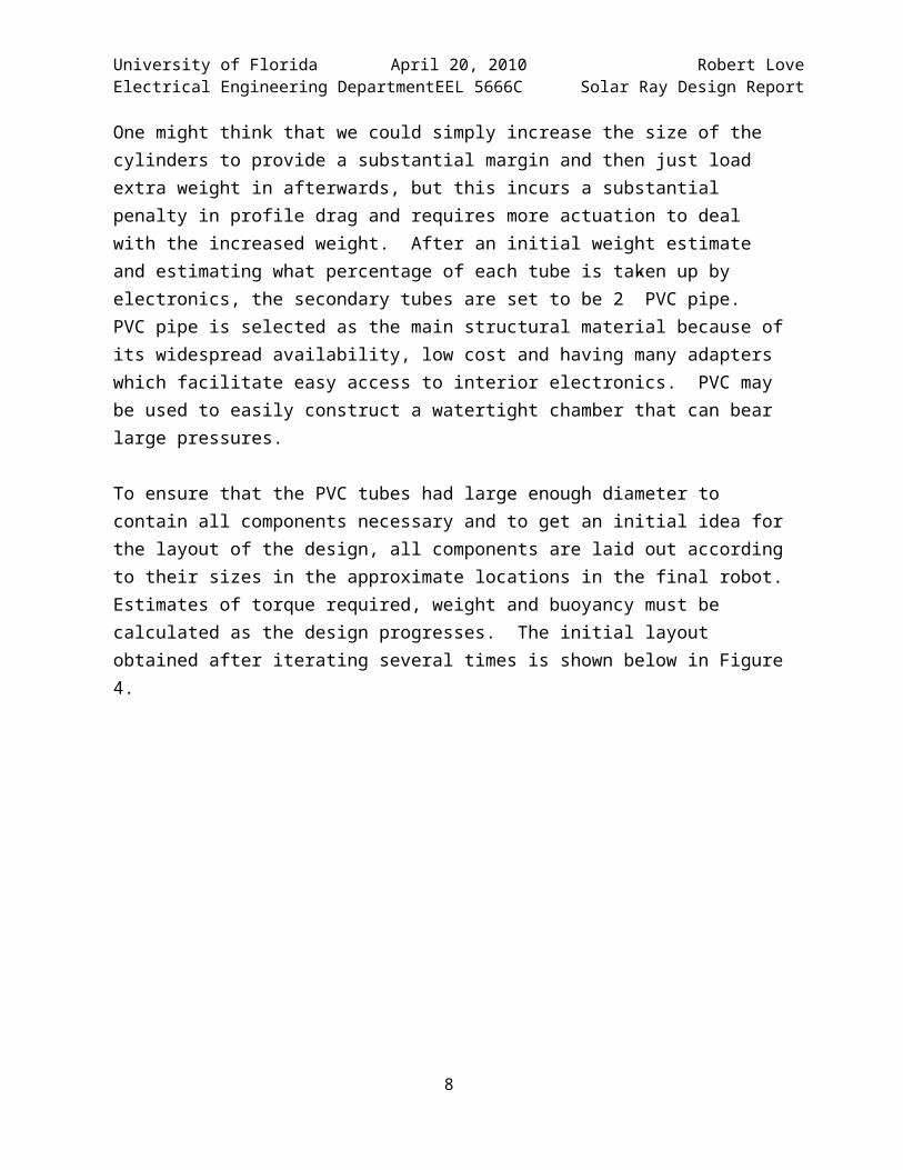
University of Florida April 20, 2010 Robert LoveElectrical Engineering Department EEL 5666C Solar Ray Design Report 5. SensorsThe sensors included on the Solar Ray are shown in Table 2 with their functions as related to the project goals. The Solar Ray has 5 sensors: 2 CdS cells to sense light, 2 Hawkeye D11S Depth Finders by Norcross Marine and a 1/3” CMOS Bullet camera with DVR and SD card. The CdS cells provide an analog reading and may be used as on/off switches or to tell the robot if light is present. The depth finders provide an alarm which runs on 6 V when the alarm goes off. Therefore these are connected to an ADC port which monitors both to provide rudimentary obstacle avoidance underwater. The depth finder may be powered with at least 6.5V to maintain accuracy though it is rated for 12V. This fact allows it to be powered directly from the power harness on the robot which is at 7.2V. The CMOS bullet camera provides video up to 720x480 resolution for 110 minutes and records video to a 4GB SD card which may be exchanged. The basic mobile platform with sensors and actuators included is seen in Figure 9.
Sensor/Description
Function
Hawkeye D11S Depth Finder Sonar
Obstacle avoidance, Solar Ray will turn away from obstacle based on which sonar alarm goes off first indicating proximity to an object
CdS Light Sensors Determine if light is hitting the vehicle for charging purposesBump Sensors Debugging and Basic Operation: Reset Button, Pause Program ButtonCamera Obtain video, store to SD cardOn/Off Switches Initial Sensor Calibration, Power On/Off (Waterproof)Table 2. Sensor Overview
Figure 9. Final Integrated Sensor and Actuator Arrangement
11

University of Florida April 20, 2010 Robert LoveElectrical Engineering Department EEL 5666C Solar Ray Design Report
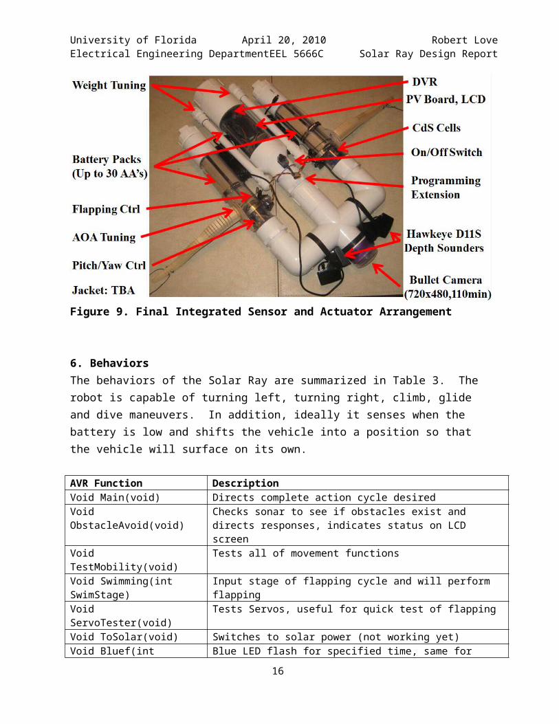
6. BehaviorsThe behaviors of the Solar Ray are summarized in Table 3. The robot is capable of turning left, turning right, climb, glide and dive maneuvers. In addition, ideally it senses when the battery is low and shifts the vehicle into a position so that the vehicle will surface on its own.
AVR Function DescriptionVoid Main(void) Directs complete action cycle desiredVoid ObstacleAvoid(void) Checks sonar to see if obstacles exist and directs responses, indicates
status on LCD screenVoid TestMobility(void) Tests all of movement functionsVoid Swimming(int SwimStage)
Input stage of flapping cycle and will perform flapping
Void ServoTester(void) Tests Servos, useful for quick test of flappingVoid ToSolar(void) Switches to solar power (not working yet)Void Bluef(int LEDwait) Blue LED flash for specified time, same for other colorsVoid Blue(void) Blue LED on constant, same for other colorsVoid Blueoff(void) Blue LED off constant, same for other colorsVoid ServoCtr(void) Center all servosVoid Rturn(int Tin) Turns robot right by flapping on left for twice time inputVoid Lturn(int Tin) Turns robot left by flapping on left for twice time inputVoid Rturnc(int Tin) Turns robot right by flapping on left for twice time input, shifts
batteries for coordinated turnVoid Lturnc(int Tin) Turns robot left by flapping on left for twice time input, shifts batteries
for coordinated turnVoid Surf(int Tin) Allows robot to surface by shifting batteries backwardsVoid Dive(int Tin) Allows robot to dive by shifting batteries forwardsVoid BumpPause(void) Pauses program until bump sensor is pressedVoid OnOffPause(void) Pauses program until on/off switch is set to onVoid GetSonar0(void) Gets left sonar valueVoid GetSonar1(void) Gets right sonar valueVoid BatteryCheck(void) Checks batteries for sufficient voltage (no hardware yet)Table 3. Overview of Solar Ray Behaviors and AVR Functions with Basic Syntax
7. Experimental Layout and Results
7. 1 Time Estimates Design of the Solar Ray took easily 40 hours of work. Selection and procurement of all parts took approximately 20 hours due to multiple trips and buying more than was required. The time spent constructing the Solar Ray if performed linearly with all parts obtained in advance is estimated to be about 40 hours, not counting hours for glue or sealants to dry. Actual time coding was around 20 hours while documenting the project on and offline took about 20 hours. Testing and getting the robot ready for testing took another 20 hours of work.
7.2 Component Testing
12

University of Florida April 20, 2010 Robert LoveElectrical Engineering Department EEL 5666C Solar Ray Design Report Waterproofing initially was unsuccessful using normal Teflon tape. However, when the PVC screws were coated with PTFE paste, the chamber was able to be waterproofed easily and endured a 12 hour test under 1 foot of water without leaking. Three 3/8” holes were drilled for wiring feed throughs, with one in the center towards the front and one in the back. The feed through holes were filled with marine epoxy unsuccessfully first, then filled with GOOP to give a watertight seal. Many of the electrical components were partially or fully coated with silicone or superglue to ensure watertightness. CdS cells, LEDs and bump sensors worked as expected.
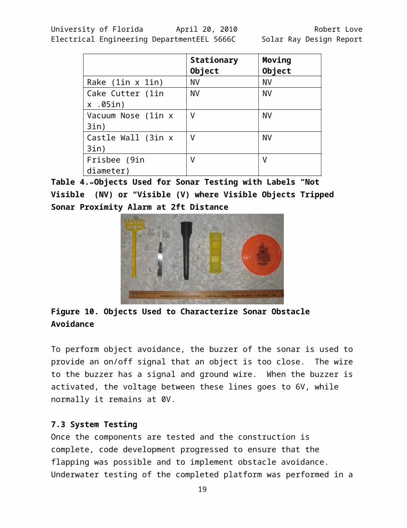
Sonar testing was initially performed in a bathtub, followed by pool testing. It was determined that the sonar would work with just 6.5V and work well at the 7.2V nominal voltage of the battery harness despite a 12V rating being stated as required to power the sonar. The voltage of the wiring harness was determined to be 8V so the sonar was connected in parallel directly to the battery harness. In the future a DC/DC converter might be used to increase the 5.5V nominal voltage on the PVR board PWM ports to 7.2-12V to supply power to the sonar. Sonar testing determined that the sonar was extremely accurate at determining the location of large stationary objects and that sonar cross talk could be minimized. However, large, fast moving objects were difficult to detect and objects with very small thickness or any with maximum dimension smaller than 1” were not detected even at 2 feet away. A summary of results is seen in Table 4 which relate to the objects in Figure 10.
Stationary Object Moving ObjectRake (1in x 1in) NV NVCake Cutter (1in x .05in) NV NVVacuum Nose (1in x 3in) V NVCastle Wall (3in x 3in) V NVFrisbee (9in diameter) V V
Table 4. Objects Used for Sonar Testing with Labels “Not Visible” (NV) or “Visible (V) where Visible Objects Tripped Sonar Proximity Alarm at 2ft Distance
Figure 10. Objects Used to Characterize Sonar Obstacle Avoidance
13

University of Florida April 20, 2010 Robert LoveElectrical Engineering Department EEL 5666C Solar Ray Design Report To perform object avoidance, the buzzer of the sonar is used to provide an on/off signal that an object is too close. The wire to the buzzer has a signal and ground wire. When the buzzer is activated, the voltage between these lines goes to 6V, while normally it remains at 0V.
7.3 System TestingOnce the components are tested and the construction is complete, code development progressed to ensure that the flapping was possible and to implement obstacle avoidance. Underwater testing of the completed platform was performed in a pool as seen in Figure 11. Unfortunately the flapping did not initially obtain enough deflection for the robot to swim very well, however adjustments to the servo linkage system are expected to be able to increase the flapping amplitude and achieve thrust production in the future. To do this the Traxxas servos will have to be hacked to provide larger than 90 degree actuation. While the solar panel is integrated into the system, the charging is not as desired since the power supply to the sonar is not yet coupled to the board and not as efficient as possible. Having two on/off switches proved extremely useful during testing to have one turn the power on/off and another to hold the flapping until desired.
Figure 11. Underwater Testing of Solar Ray with Right Wing Flapping (Note ripple).
7.4 Final Integrated System with Mobile PlatformDuring testing, the original Hitec servos and one of the sonar sensor control boxes were damaged due to water impingement. As a result, the final system used the Traxxas High Torque Waterproof servos to actuate the flapping and both of the control boxes for the D11S were filled with silicone. The strings used to actuate the flapping snapped repeatedly, so the strings were coated with superglue. The coating made the strings stronger and easier to thread through the spar, but they were also more brittle. A better solution is needed in the future. The final setup with the internal components marked is shown in Figure 12.
14

University of Florida April 20, 2010 Robert LoveElectrical Engineering Department EEL 5666C Solar Ray Design Report
Figure 12. Final Integrated System with Mobile Platform
8. Conclusions and Future RecommendationsThis project taught me how quickly costs can escalate in an engineering project as design requirements necessitated upgrades to the servos and expensive sensors. It also reemphasized how design simplicity is necessary since the amount that can go wrong goes up very quickly as the system gets more complex. A lot of extra wire must be used to ensure that everything is accessible and interchangeable. I enjoyed learning more about electrical engineers, how to use digital logic, a lot about the process of systems integration and even more about how designing flexibility into the system is essential to the next iteration’s success. In the future I will attempt to build the wings spar/hydrofoils with a hard plastic instead of wood, make the wing trailing edge more flexible and possibly actuate the wing differently. Ultimately the project was successful at producing a prototype which detects and tries to avoid obstacles, but further work and investment is required before a truly mission capable flapping wing Solar Ray can be fielded.
9. Documentation9.1 AcknowledgementsThanks to, Dr. Arroyo and Dr. Schwartz for organizing the class. Thanks to our TA’s and board designers Thomas Vermeer and Mike Pridgen for their invaluable suggestions. Thanks to Gabe Isham and Patrick Sullivan at Norcross Marine/Hawkeye for providing new D11S units at refurbished prices. Thanks to Deloris at Alterations by Deloris for helping me design the jacket. Thanks to Josh Jeske for documenting the Coin Frog well and giving me a start on how to design the underwater electronics. Thanks to all the researchers working on flapping wing UUV’s and SAUV’s who freely share their expertise.
15
University of Florida April 20, 2010 Robert LoveElectrical Engineering Department EEL 5666C Solar Ray Design Report
9.2 References[1] J.T. Schaefer, A.P. Summers, Batoid Wing Skeletal Structure: Novel Morphologies, Mechanical Implications and Phylogenetic Patterns, Journal of Morphology, v. 264, pp. 298-305, 2005.
[2] R. Ramamurti, J. Geder, J. Palmisano, B. Ratna, W. C. Sandberg, Computations of Flapping Flow Propulsion for Unmanned Underwater Vehicle Design, AIAA Journal, v. 48, n. 1, January 2010, doi: 10.2514/1.43389.
[3] L.J. Rosenberger, M.W. Westneat, Functional Morphology of Undulatory Pectoral Fin Locomotion in the Stingray Taeniura Lymma (Chondrichthyes: Dasyatidae), The Journal of Experimental Biology, v. 202, pp 3523-3539, 1999.
[4] K.W. Moored, W. Smith, J.M. Hester, W. Chang, H. Bart-Smith, Investigating the Thrust Production of a Myliobatoid-Inspired Oscillating Wing, 2008
[5] J.A. Walker, Kinematics and Performance of Maneuvering Control Surfaces in Teleost Fishes, IEE Journal of Oceanic Engineering, v. 29, n. 3, July 2004.
[6] S. Yang, J. Qiu, X. Han, Kinematics Modeling and Experiments of Pectoral Oscillation Propulsion Robotic Fish, Journal of Bionic Engineering, v. 6, pp. 174-179, 2009.
[7] Z. Yong-hua, Z. Shi-wu, Y. Jie, K.H. Low, Morphologic Optimal Design of Bionic Undulating Fin Based on Computational Fluid Dynamics, Proceedings of the IEEE International Conference on Mechatronics and Automation, Aug. 5-8, 2007.
[8] H. Soueid, L. Guglielmini, C. Airiau, A. Bottaro, Optimization of the Motion of a Flapping Airfoil Using Sensitivity Functions, Computers and Fluids, v. 38, pp. 861-874, 2009.
[9] L.J. Rosenberger, Pectoral Fin Locomotion in Batoid Fishes: Undulation Versus Oscillation, The Journal of Experimental Biology, v. 204, pp. 379-394, 2001.
[10] R.P. Clark, A.J. Smits, Thrust Production and Wake Structure of a Batoid-Inspired Oscillating Fin, Journal of Fluid Mechanics, v. 562, pp. 415-429, 2006, doi:10.1017/S0022112006001297.
[11] K.V. Rozhdestvensky, V.A. Ryzhov, Aerohydrodynamics of Flapping-Wing Propulsors, Progress in Aerospace Sciences, v. 39, pp. 585-633, 2003, doi: 10.1016/S0376-0421(03)00077-0.
16

University of Florida April 20, 2010 Robert LoveElectrical Engineering Department EEL 5666C Solar Ray Design Report [12] S.A. Combes, T.L. Daniel, Shape, Flapping and Flexion: Wing and Fin Design for Forward Flight, The Journal of Experimental Biology, v. 204, pp. 2073-2085, 2001
[13] J. M. Dellis, Unsteady Aerodynamics Studies, http://translate.google.com/translate?client=tmpg&hl=en&u=http://urvam.free.fr/modules/wiwimod/index.php%3Fpage%3DAERODYNAMIQUE%2BINSTATIONNAIRE,%2BETUDES.%26back%3DA%25E9rodynamique&langpair=fr|en, 2008.
[14] Anonymous, Society of Robots, “How to Waterproof a Servo”, http://www.societyofrobots.com/actuators_waterproof_servo.shtml, 2010.
[15] “Aqua Ray”, http://www.drives.co.uk/images/news/Festo%20ray.jpg, http://www.festo.com/inetdomino/coorp_sites/en/544ca592e1ff5d58c12572b9006e05bd.htm, 2010.
[16] Anonymous, “Solar Powered AUV”, http://ausi.org/research/sauv/, 2010.
[17] Anoynmous, “Cownose Ray Swimming”, http://vimeo.com/7697526, 2010.
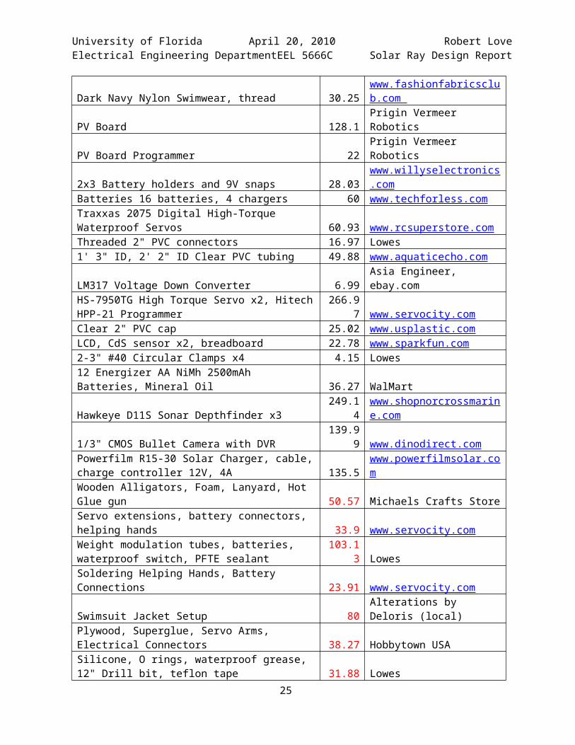
Appendix A. Parts List with Total Project Cost (Excluding Excess Parts)
PurchasesAmount Supplier
PVC tubing, PVC cement, connectors, silicone gel 50 LowesDark Navy Nylon Swimwear, thread 30.25 www.fashionfabricsclub.com PV Board 128.1 Prigin Vermeer RoboticsPV Board Programmer 22 Prigin Vermeer Robotics2x3 Battery holders and 9V snaps 28.03 www.willyselectronics.comBatteries 16 batteries, 4 chargers 60 www.techforless.comTraxxas 2075 Digital High-Torque Waterproof Servos 60.93 www.rcsuperstore.comThreaded 2" PVC connectors 16.97 Lowes1' 3" ID, 2' 2" ID Clear PVC tubing 49.88 www.aquaticecho.comLM317 Voltage Down Converter 6.99 Asia Engineer, ebay.comHS-7950TG High Torque Servo x2, Hitech HPP-21 Programmer 266.97 www.servocity.comClear 2" PVC cap 25.02 www.usplastic.comLCD, CdS sensor x2, breadboard 22.78 www.sparkfun.com2-3" #40 Circular Clamps x4 4.15 Lowes12 Energizer AA NiMh 2500mAh Batteries, Mineral Oil 36.27 WalMart
Hawkeye D11S Sonar Depthfinder x3 249.14www.shopnorcrossmarine.com
1/3" CMOS Bullet Camera with DVR 139.99 www.dinodirect.comPowerfilm R15-30 Solar Charger, cable, charge controller 12V, 4A 135.5 www.powerfilmsolar.com
17

University of Florida April 20, 2010 Robert LoveElectrical Engineering Department EEL 5666C Solar Ray Design Report
Wooden Alligators, Foam, Lanyard, Hot Glue gun 50.57 Michaels Crafts StoreServo extensions, battery connectors, helping hands 33.9 www.servocity.comWeight modulation tubes, batteries, waterproof switch, PFTE sealant 103.13 LowesSoldering Helping Hands, Battery Connections 23.91 www.servocity.comSwimsuit Jacket Setup 80 Alterations by Deloris (local)Plywood, Superglue, Servo Arms, Electrical Connectors 38.27 Hobbytown USASilicone, O rings, waterproof grease, 12" Drill bit, teflon tape 31.88 LowesSuperglue, Silicone, 1 minute Epoxy, dremel cutters, screwdrivers 40.7 LowesHitec HS65HB Feather Servos, Ultra Electrical Connectors 65.84 Hobbytown USATotal Spent 1801.17
Note: Multiple electrical components were supplied by the IMDL lab including bump sensors, electrical wire and connections, resistors and machine shop equipment. Few additional tools were required, but I also had a drill, screwdrivers, needle nose pliers, wire strippers, a dremel set, tape measure, micrometer, sandpaper, a soldering iron, hot glue gun and exacto knife.
Appendix B. Essential Calculations (Initial Design)Basic Sizing Information Main Cylinder Length 0.13 m Main Cylinder OD 0.0889 m Main Cylinder ID 0.0762 mDual Side Cylinder OD 0.060325 mDual Side Cylinder ID 0.0508 mDual Side Cylinder Lengths 0.25 mTotal Length of Fuselage 0.60625 noneWing Span 0.9144 mWing Length 0.29845 mWing Chord 0.25 mWing Average Thickness (est) 0.00635 mTube Offset 0.06985 m
Frontal Reference Area0.295113
8 m^2
Single Wing Reference Area (tri)0.037306
3 m^2
Body Reference Area0.041719
5 m^2
Total Reference Area0.079025
8 m^2Anticipated Movement Vmax=Max Forward Velocity 0.5 m/sVcruise=1/2 max forward velocity 0.25 m/s
18
University of Florida April 20, 2010 Robert LoveElectrical Engineering Department EEL 5666C Solar Ray Design Report
Kinematic Profile Wing Beat Frequency (Max) 0.5 HzWing Beat Period 2 sPhase Lag (TE to LE) 90 degreesFlapping Amplitude 0.3 mStrouhal Number (A/Vt) 0.3 none
Reynolds number1.245E+0
8 none
Boyancy Estimate
Air Displaced Main Cylinder0.003693
9 m^3
Air Displaced Dual Cylinder0.003283
5 m^3Air Displaced Connections 0.00139 m^3
Max Air Displaced0.006977
4 m^3
Max Boyant Force6.968961
2 kg% Electronics Main Cylinder 0.3
% Electronics Dual Cylinders (est)0.103913
5 % Electronics Dual Cylinders 0.1
Real Air Displaced0.006930
8 m^3
Total Boyant Force6.922501
5 kg
Weight Estimate Tried to overestimate… PVC main tube & caps: est 0.2 kgPVC dual side tubes & caps: est 0.1666667 kgBasic Wing Structure 0.5 kgServos 0.18 kgPressure 0.025 kgCamera 0.198 kgAccel 0.025 kgSonar: est 0.85 kgBatteries 1 kgSolar Charger 0.29 kgSkin: est 0.2 kgStructures: est 0.35 kgBoard 0.05668 kgRandom Wiring 0.1 kg
19

University of Florida April 20, 2010 Robert LoveElectrical Engineering Department EEL 5666C Solar Ray Design Report
Total Weight of Robot 4.1413467 kg
Solar Area Check Max Length Solar Panel 0.25 mMax Width Solar Panel 0.20955 m
Max Surface Area for Solar Panels0.052387
5 m^2
Actual Surface Area of Solar Panel0.155806
1 m^2
Depth Calculations Maximum Depth 3.048 mWater Pressure at Max Depth 3093.464 kg/m^2 (Pa)
Total Pressure at Max Depth (guage)104393.4
6 kg/m^2 (Pa)
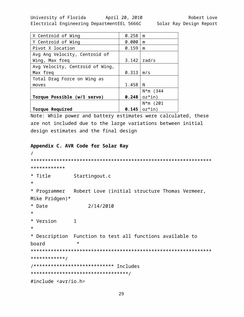
Force/Torque Calculations Min Drag Coeff (all frontal areas) 0.3 noneEstimated Drag Coeff (all frontal areas) 0.5 noneMax Drag Coeff (do something if this reached) 0.8 noneFrontal Drag Force (est) = Thrust Req 18.445 NFrontal Drag Force (est) = Thrust Req Cruise 4.611 NX Centroid of Wing 0.258 mY Centroid of Wing 0.000 mPivot X location 0.159 mAvg Ang Velocity, Centroid of Wing, Max freq 3.142 rad/sAvg Velocity, Centroid of Wing, Max freq 0.313 m/sTotal Drag Force on Wing as moves 1.458 NTorque Possible (w/1 servo) 0.248 N*m (344 oz*in)Torque Required 0.145 N*m (201 oz*in)
Note: While power and battery estimates were calculated, these are not included due to the large variations between initial design estimates and the final design
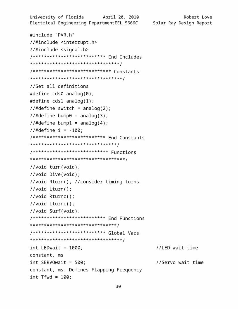
Appendix C. AVR Code for Solar Ray/**************************************************************************** Title Startingout.c ** Programmer Robert Love (initial structure Thomas Vermeer, Mike Pridgen)** Date 2/14/2010 ** Version 1 ** Description Function to test all functions available to board ****************************************************************************//**************************** Includes **********************************/
20

University of Florida April 20, 2010 Robert LoveElectrical Engineering Department EEL 5666C Solar Ray Design Report #include <avr/io.h>#include "PVR.h"//#include <interrupt.h>//#include <signal.h>/************************** End Includes ********************************//**************************** Constants *********************************///Set all definitions#define cds0 analog(0);#define cds1 analog(1);//#define switch = analog(2);//#define bump0 = analog(3);//#define bump1 = analog(4);//#define i = -100;/************************** End Constants *******************************//*************************** Functions **********************************///void turn(void);//void Dive(void);//void Rturn(); //consider timing turns//void Lturn();//void Rturnc();//void Lturnc();//void Surf(void);/************************** End Functions *******************************//************************** Global Vars *********************************/int LEDwait = 1000; //LED wait time constant, msint SERVOwait = 500; //Servo wait time constant, ms: Defines Flapping Frequencyint Tfwd = 100;int Tctr = 0; int Tbck = -100;int Hhi = 75;int Hctr = 25;int Hlo = -150;
//Actuator Constants (Used by Ctr, Swimming, )int Lhi = 45;//Hhi; *** //high point for servo C1 (Hitec), Leftint Lctr = 0; //Hctr;int Llo = -45;//Hlo; //low point for servo C1 int Rhi = 35;//Hhi; lower //high point for servo D1 (Hitec), Leftint Rctr = 0;//Hctr;int Rlo = -60;//-23;//Hlo; *** upper //low point for servo D1
21
University of Florida April 20, 2010 Robert LoveElectrical Engineering Department EEL 5666C Solar Ray Design Report
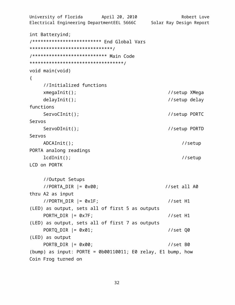
//Sensor Constantsint bumpc = 0; //start value of bump sensor countint Cds0; //value for CDS0int Cds0thresh; //value for CDS0 threshold light vs darkint Cds1; //value for CDS1int Cds1thresh; //value for CDS1 threshold light vs darkint Son0;int Son1;int Son0flag;int Son1flag;int Batt;int Batteryind;/************************* End Global Vars ******************************//*************************** Main Code **********************************/void main(void){
//Initialized functionsxmegaInit(); //setup XMegadelayInit(); //setup delay functionsServoCInit(); //setup PORTC ServosServoDInit(); //setup PORTD ServosADCAInit(); //setup PORTA
analong readingslcdInit(); //setup LCD on
PORTK
//Output Setups//PORTA_DIR |= 0x00; //set all A0 thru A2 as input//PORTH_DIR |= 0x1F; //set H1 (LED) as output,
sets all of first 5 as outputsPORTH_DIR |= 0x7F; //set H1 (LED) as
output, sets all of first 7 as outputsPORTQ_DIR |= 0x01; //set Q0 (LED) as
outputPORTB_DIR |= 0x00; //set B0 (bump) as input:
PORTE = 0b00110011; E0 relay, E1 bump, how Coin Frog turned on
22

University of Florida April 20, 2010 Robert LoveElectrical Engineering Department EEL 5666C Solar Ray Design Report
PORTJ_DIR |= 0x00; //set J0 (bump) as input: PORTE = 0b00110011; E0 relay, E1 bump, how Coin Frog turned on
//Specify Important ConstantsServoCtr(); //Set all servos to center positions
redf(1000);whitef(1000);bluef(1000);
//Display going into main programlcdGoto(0,0); //move LCD cursor to the
first line (Line o) of LCDlcdString("Solar Ray OS1"); //display on top line (Line
0) of LCDdelay_ms(1000); //delay 1 second to
let everything be ok
//ServoC1(Llo); //Set high and low positions //Single Servo Position Testing
//ServoD1(Rhi);//ServoC1(Lhi-15); //High position//Single Servo Position Testing//ServoD1(Rlo+15);//ServoC1(Llo+15); //Low position//ServoD1(Rhi-15);
//ServoC1(Lhi-15); //ServoD1(Rlo+15);//delay_ms(500);//ServoC1(Llo+15);//ServoD1(Rhi-15);
OnOffPause(); //Keeps program waiting until turn on the second switch//ServoTester(500); // //Sends into main loop which initiates "swimming"/servo testing
while(1){Swimming(1); //Stage 1 flap,
Swimming(SERVOwait,Hctr,Hlo,Hhi,1);GetSonar0(); //gets sonar value, prints to LCD
23

University of Florida April 20, 2010 Robert LoveElectrical Engineering Department EEL 5666C Solar Ray Design Report
GetSonar1(); //gets sonar value, prints to LCDObstacleAvoid(); //Check for obstaclesdelay_ms(250);Swimming(2); //Stage 2 flap,GetSonar0(); //gets sonar value, prints to LCDGetSonar1(); //gets sonar value, prints to LCDObstacleAvoid(); //Check for obstaclesdelay_ms(250);Swimming(3);GetSonar0(); //gets sonar value, prints to LCDGetSonar1(); //gets sonar value, prints to LCDObstacleAvoid(); //Check for obstaclesdelay_ms(250);Swimming(4);GetSonar0(); //gets sonar value, prints to LCDGetSonar1(); //gets sonar value, prints to LCDObstacleAvoid(); //Check for obstaclesdelay_ms(250);BatteryCheck();}
//Insert all code to loop through while running main program:while(1){lcdGoto(1,0); //move LCD cursor to the second
line (Line 1) of LCDlcdString("Main"); //display on second linedelay_ms(100); //delay 100ms (so running
at 10Hz)}
}/*************************** End Main Code ******************************/
/*************************** Functions **********************************/void ObstacleAvoid(void)/**************************************************************************** Function: Will simulate obstacle avoidance (use on/off switch) *****************************************************************************/{ //Obstacle avoidance:
24
University of Florida April 20, 2010 Robert LoveElectrical Engineering Department EEL 5666C Solar Ray Design Report
//red(200);lcdGoto(1,14); //move LCD cursor to the
second line (Line 1) of LCDlcdString("OBS"); //display on second
line//First loop: flap straight until press on/off switch//Second loop: flap only right until press on/off switch//Third loop: flap only left until press on/off switch
//Use Son0flag and Son1flag to determine where to go (these are global variables)
//int Son0ind;//int Son1ind;//int Sonthresh;//Son0ind=GetSonar0();//Son1ind=GetSonar1();//Sonthresh=500;
if (Son0flag==1 && Son1flag==1){ //if statements first both, then either one, just continue flapping if both ok
Surf(1000);}else if (Son0flag==1){Rturn(500); //Each of these turns for 1 secondRturn(500);Rturn(500);}else if (Son1flag==1){Lturn(500); //Each of these turns for 1 secondLturn(500); Lturn(500);Lturn(500);}//redoff(200);
}
void TestMobility(int Tin)/**************************************************************************** Function: Tests the Mobility functions (Turns and Dive/Surface) *****************************************************************************/
25

University of Florida April 20, 2010 Robert LoveElectrical Engineering Department EEL 5666C Solar Ray Design Report {
lcdGoto(1,0);lcdString("Test Mobility");
int moveT=500;Dive(moveT); //,Tfwd,Tctr); //includes a move (dive) time, moves batteries forward
then back to ctrRturn(moveT);//,Hctr,Hlo,Hhi);Lturn(moveT);//,Hctr,Hlo,Hhi);Rturnc(moveT);//,Hctr,Hlo,Hhi,Tctr,Tfwd);Lturnc(moveT);//,Hctr,Hlo,Hhi,Tctr,Tfwd);Surf(moveT); //,Tbck,Tctr);
}
void Swimming(int SwimStage)/**************************************************************************** Function: Will direct swimming based on certain stage indicator *****************************************************************************/{ //Basic Swimming Straight
lcdGoto(1,0); //move LCD cursor to the second line (Line 1) of LCD
lcdString("Servo Test"); //display on second line
white();if (SwimStage==1){ // Both Wings go high to startServoC1(Lhi); ServoD1(Rhi);}else if (SwimStage==2){ //Both Wings Return to centerServoC1(Lctr);ServoD1(Rctr);}else if (SwimStage==3){ //Both Wings go lowServoC1(Llo); ServoD1(Rlo);}else if (SwimStage==4){ //Both Wings Return to centerServoC1(Lctr); ServoD1(Rctr);}
26

University of Florida April 20, 2010 Robert LoveElectrical Engineering Department EEL 5666C Solar Ray Design Report
whiteoff();}
void ServoTester(int Tin)/**************************************************************************** Function: Will perform initial servo testing *****************************************************************************/{ //Initial Servo Testing (Simply moves servos back and forth)
lcdGoto(0,0); //move LCD cursor to the second line (Line 1) of LCD
lcdString("Servo Test"); //display on second line
while(1){whitef(500); //flash white LEDServoC1(Lhi); ServoD1(Rlo);//ServoC2(Tbck);//ServoD2(Tbck);delay_ms(Tin);ServoC1(Llo);ServoD1(Rhi);//ServoC2(Tfwd);//ServoD2(Tfwd);delay_ms(Tin);//whiteoff();}
}
void ToSolar(void){
lcdGoto(1,0); //move LCD cursor to the second line (Line 1) of LCD
lcdString("Solar"); //display on second line//Test to see if will switch
}
//LED functions: all simply flash the LED for time LEDwaitvoid redf(int LEDwait)
27

University of Florida April 20, 2010 Robert LoveElectrical Engineering Department EEL 5666C Solar Ray Design Report {PORTH_OUT &= ~(0x18); //Turns ON Port H, Pin 3,4delay_ms(LEDwait);PORTH_OUT |=0x18; //Turns OFF Port H, Pin 3,4}void redLf(int LEDwait) //Orange/Yellow, H0 {PORTH_OUT &= ~(0x04); //Turns ON Port H, Pin 3delay_ms(LEDwait);PORTH_OUT |=0x04; //Turns OFF Port H, Pin 3}void redRf(int LEDwait) //Red/Brown, H1{PORTH_OUT &= ~(0x08); //Turns ON Port H, Pin 4delay_ms(LEDwait);PORTH_OUT |= 0x08; //Turns ON Port H, Pin 4}void whitef(int LEDwait){PORTH_OUT &= ~(0x02); //Turns ON Port H, Pin 1delay_ms(LEDwait);PORTH_OUT |= 0x02; //Turns OFF Port H, Pin 1}void bluef(int LEDwait){PORTH_OUT &= ~(0x05); //Turns ON Port H, Pin 0,2delay_ms(LEDwait);PORTH_OUT |= 0x05; //Turns OFF Port H, Pin 0,2}//Constant On'svoid red(int LEDwait){PORTH_OUT &= ~(0x18); //Turns ON Port H, Pin 3,4}void redL(void) //Orange/Yellow, H0 {PORTH_OUT &= ~(0x04); //Turns ON Port H, Pin 3}void redR(void) //Red/Brown, H1{PORTH_OUT &= ~(0x08); //Turns ON Port H, Pin 4}void white(void){PORTH_OUT &= ~(0x02); //Turns ON Port H, Pin 1}void blue(void){PORTH_OUT &= ~(0x05); //Turns ON Port H, Pin 0,2}//Constant Offs
28
University of Florida April 20, 2010 Robert LoveElectrical Engineering Department EEL 5666C Solar Ray Design Report void redoff(void){PORTH_OUT |=0x18; //Turns OFF Port H, Pin 3,4}void redLoff(void) //Orange/Yellow, H0 {PORTH_OUT |=0x04; //Turns OFF Port H, Pin 3}void redRoff(void) //Red/Brown, H1{PORTH_OUT |=0x08; //Turns ON Port H, Pin 4}void whiteoff(void){PORTH_OUT |=0x02; //Turns ON Port H, Pin 1}void blueoff(void){PORTH_OUT |=0x05; //Turns ON Port H, Pin 0,2}//PORTH_OUT &= ~(0x18); //Turns ON Port H, Pin 6 AND Pin 7//PORTH_OUT |= 0x18; //Turns OFF Port H, Pin 6 AND Pin 7
//PORTH_OUT &= ~(0x02); //Turns ON Port H, Pin 2//delay_ms(LEDwait);//PORTH_OUT |= 0x02; //Turns OFF Port H, Pin 2
//PORTH_OUT &= ~(0x10); //Turns ON Port H, Pin 5//delay_ms(LEDwait);//PORTH_OUT |= 0x10; //Turns OFF Port H, Pin 5
void ServoCtr(void)/**************************************************************************** Function: Centers all Servo Locations *****************************************************************************/{//Center all servosServoC2(Lctr);ServoD2(Rctr);ServoC1(Lctr);ServoD1(Rctr);}
void Rturn(int Tin)/***************************************************************************
29
University of Florida April 20, 2010 Robert LoveElectrical Engineering Department EEL 5666C Solar Ray Design Report * Function: Will make robot turn right *****************************************************************************/{ //Turn Right Maneuver: (non coordinated-so only wings, timed), LED on toward the way turning
redR();lcdGoto(1,14); //move LCD cursor to the
second line (Line 1) of LCDlcdString("R"); //display on second
lineServoC1(Llo); //LeftServoD1(Rctr); //Rightdelay_ms(Tin);ServoC1(Lhi);ServoD1(Rctr);delay_ms(Tin);redRoff();
}
void Lturn(int Tin)/**************************************************************************** Function: Will make robot turn left *****************************************************************************/{ //Turn Left Maneuver: (non coordinated-so only wings, timed)
redL();lcdGoto(1,14); //move LCD cursor to the
second line (Line 1) of LCDlcdString("L"); //display on second
lineServoC1(Lctr);ServoD1(Rlo);delay_ms(Tin);ServoC1(Lctr);ServoD1(Rhi);delay_ms(Tin);redLoff();
}
void Surf(int Tin)/***************************************************************************
30

University of Florida April 20, 2010 Robert LoveElectrical Engineering Department EEL 5666C Solar Ray Design Report * Function: Will make robot surface *****************************************************************************/{ //Surface Maneuver: batteries back, white LED on
white();lcdGoto(1,14); //move LCD cursor to the
second line (Line 1) of LCDlcdString("S"); //display on second lineServoC2(Tbck);ServoD2(Tbck);delay_ms(Tin);ServoC2(Tctr);ServoD2(Tctr);whiteoff();
}
void Dive(int Tin)/**************************************************************************** Function: Will make robot dive *****************************************************************************/{ //Dive Maneuver: Pull Batteries Forward, Flap for some duration seconds, blue lights on
blue();lcdGoto(1,14); //move LCD cursor to the
second line (Line 1) of LCDlcdString("D"); //display on second
lineServoC2(Tfwd);ServoD2(Tfwd);delay_ms(Tin);ServoC2(Tctr);ServoD2(Tctr);blueoff();
}/************************************************************************/
void BumpPause(void)/**************************************************************************** Function: Pauses Until Bump Sensor is Pressed *
31
University of Florida April 20, 2010 Robert LoveElectrical Engineering Department EEL 5666C Solar Ray Design Report ****************************************************************************/{
//SIMPLE WORKING TOUCH SENSOR HOLDwhile((PORTB_IN & 0b0000001) == 0b00000001) //Johnathan Coad, binary format,
Code pauses loop unless button is pressed{}
//Bump Sensors//delay_ms(4000);// While switch closed, wait for removal //SEARCH FOR PINE definition! Coin Frog//while((PINE & 0b00000010) == 0) {
//}// Secondary check for bin reattachment//while((PINE & 0b00000010) != 0) {
// While switch open, wait for replacement//while((PINE & 0b00000010) != 0) {//}//}
//WORKING TOUCH SENSOR HOLD (3 lines)// while((PORTB_IN & 0b0000001) == 0b00000001) //Johnathan Coad, binary format, Code pauses loop unless button is pressed// {redf(100);// delay_ms(10);// } //consider adding an "if" statement and operating on bumpc counter->if even, continues loop, if odd, stops loop until pressed again}
void OnOffPause(void)/**************************************************************************** Function: Pauses Until Bump Sensor is Pressed *****************************************************************************/{
//SIMPLE WORKING TOUCH SENSOR HOLDwhile((PORTJ_IN & 0b0000001) == 0b00000001) //Johnathan Coad, binary format,
Code pauses loop unless button is pressed
32

University of Florida April 20, 2010 Robert LoveElectrical Engineering Department EEL 5666C Solar Ray Design Report
{}
}
void GetCds(void){ //CdS Sensors, get value and display
int Cds0;int Cds1;Cds0=ADCA0();Cds1=ADCA1();lcdGoto(1,0);lcdInt(Cds0);lcdGoto(1,4);lcdInt(Cds1);
}
void GetSonar0(void){ //Sonar Sensors, get value and display
//int Son0flag;//int Son0;Son0=ADCA2();if(Son0>500){
Son0flag=1;lcdGoto(1,2);lcdString("GO RIGHT!");//return Son0flag;
}else if (Son0<=500){
Son0flag=0;//return Son0flag;
}lcdGoto(1,0);lcdInt(Son0flag);
}
void GetSonar1(void){ //Sonar Sensors, get value and display
//int Son1flag;//int Son1;Son1=ADCA3();if(Son1>500){
33

University of Florida April 20, 2010 Robert LoveElectrical Engineering Department EEL 5666C Solar Ray Design Report
Son1flag=1;lcdGoto(1,2);lcdString("GO LEFT!");//return Son1flag;
}else if (Son1<=500){
Son1flag=0;//return Son1flag;
}lcdGoto(1,1);lcdInt(Son1flag);
}
void BatteryCheck(void){
//Batt=ADCA4();//if(Batt<500){//Batteryind=0;//}Batteryind=1;
}
34