millennia pro s series - spectra-physics
TRANSCRIPT

Millennia Pro s-SeriesDiode-Pumped, CW Visible Laser Systems
User’s Manual
1335 Terra Bella AvenueMountain View, CA 94043
Part Number 0000-320A, Rev. BNovember 2005
These laser products comply with performance stan-dards of United States Code of Federal Regulations,Title 21, Chapter 1 – Food and Drug Administration,Department of Health and Human Services,Subchapter J – Parts 1040.10 or 1040.11, as applicable.


Preface
This manual contains information you need in order to safely install, oper-ate, maintain, and service your Millennia Pro s-Series diode-pumped, con-tinuous-wave, visible laser. The system comprises the Millennia Pro s laserhead, either a Model J40 or Model J80 power supply, and the MillenniaController (a table-top unit provided with the system).
There are four different models of the laser head, according to their outputpower: the Millennia Pro 5sJ, 6sJ, 8sJ, or 10sJ. The laser head is water-cooled, and an optional chiller is available for this purpose.
Chapter 1, “Introduction,” contains a brief description of the MillenniaPro s-Series system and the accessories provided with it.
Chapter 2, “Laser Safety,” contains important information on safety. AMillennia Pro s laser is a Class IV device and, as such, emits laser radiationthat can permanently damage eyes and skin. This section contains informa-tion about these hazards and offers suggestions on how to safeguard againstthem. To minimize the risk of injury or expensive repairs, be sure to readthis chapter—then carefully follow these instructions.
Chapter 3, “Laser Description,” contains a short section on laser theoryregarding the Nd:YVO4 crystal and second harmonic generation used in theMillennia Pro s-Series. It is followed by a more detailed description of thelaser system. This chapter concludes with tables of system specificationsand outline drawings.
Chapter 4, “Controls, Indicators, and Connections,” describes the Millenniacontrols, and Chapter 5 “Installation” helps you prepare your site for theinstallation of the system by a Spectra-Physics technician.
Chapter 6, “Operation,” describes in detail how to operate the laser.
Chapter 7, “Maintenance and Troubleshooting,” is intended to help youguide your Spectra-Physics field service engineer to the source of anyproblems. Do not attempt repairs yourself while the unit is still under war-ranty; instead, report all problems to Spectra-Physics for warranty repair.This chapter includes a replacement parts list.
Chapter 8, “Customer Service,” contains a list of world-wide Spectra-Phys-ics Service Centers you can call if you need help. Should you experienceany problems or you are in need of technical information or support, pleasecontact Spectra-Physics.
iii
Millennia Pro s-Series Diode-Pumped, CW Visible Lasers
This product has been tested and found to conform to Directive 73/23/EECgoverning product safety using standards EN 60950: 1997, EN 61010-1:2001 and EN 60825-1: 1994, and it conforms to Directive 89/336/EECgoverning electromagnetic compatibility using standard EN 61326-1 w/A1: 1997 as listed in the official Journal of the European Communities.Refer to the “CE Declaration of Conformity” statements in Chapter 2.
This product conforms to the requirements of 21 CFR 1040.10 CDRH andare compliant to Underwriters Laboratory UL1950 and uses a power sup-ply that is a UL recognized (ULR) component.
This equipment has been designed and tested to comply with the limits fora Class A digital device pursuant to Part 15 of the FCC Rules.
Every effort has been made to ensure that the information in this manual isaccurate. All information in this document is subject to change withoutnotice. Spectra-Physics makes no representation or warranty, either expressor implied, with respect to this document. In no event will Spectra-Physicsbe liable for any direct, indirect, special, incidental or consequential dam-ages resulting from any defects in this documentation.
Finally, if you encounter any difficulty with the content or style of thismanual, or encounter problems with the laser itself, please let us know. Thelast page of this manual is a form to aid in bringing such problems to ourattention.
Thank you for your purchase of Spectra-Physics instruments.
iv

Environmental Specifications
CE Electrical Equipment Requirements
Refer to specification EN-309, “Plug, Outlet and Socket Couplers for Indus-trial Uses,” listed in the official Journal of the European Communities, forinformation regarding the equipment needed in order to provide the electri-cal service listed under “Specifications” at the end of Chapter 3.
Environmental Specifications
The environmental conditions under which the laser system will functionare listed below:
Indoor useAltitude: up to 3000 mTemperatures: 18°C to 35°CMaximum relative humidity: 85% non-condensing for temperatures up to
35°C.Mains supply voltage: do not exceed ± 10% of the nominal voltageInsulation category: IIPollution degree: 2
FCC Regulations
This equipment has been tested and found to comply with the limits for aClass A digital device pursuant to Part 15 of the FCC Rules. These limitsare designed to provide reasonable protection against harmful interferencewhen the equipment is operated in a commercial environment. This equip-ment generates, uses and can radiate radio frequency energy and, if notinstalled and used in accordance with the instruction manual, may causeharmful interference to radio communications. Operation of this equipmentin a residential area is likely to cause harmful interference in which casethe user will be required to correct the interference at his own expense.
Modifications to the laser system not expressly approved by Spectra-Physicscould void your right to operate the equipment.
CDRH and UL Regulations
This product conforms to the requirements of 21 CFR 1040.10 CDRH andare compliant to Underwriters Laboratory UL1950 and are listed as ULRfor recognized components.
v


Table of Contents
Preface . . . . . . . . . . . . . . . . . . . . . . . . . . . . . . . . . . . . . . . . . . . . . . . . . . . . . . . . . . . . . . iii
Environmental Specifications. . . . . . . . . . . . . . . . . . . . . . . . . . . . . . . . . . . . . . . . . . . . vCE Electrical Equipment Requirements . . . . . . . . . . . . . . . . . . . . . . . . . . . . . . . . . . . . . . . . . . . . . . . . vEnvironmental Specifications . . . . . . . . . . . . . . . . . . . . . . . . . . . . . . . . . . . . . . . . . . . . . . . . . . . . . . . . vFCC Regulations . . . . . . . . . . . . . . . . . . . . . . . . . . . . . . . . . . . . . . . . . . . . . . . . . . . . . . . . . . . . . . . . . vCDRH and UL Regulations . . . . . . . . . . . . . . . . . . . . . . . . . . . . . . . . . . . . . . . . . . . . . . . . . . . . . . . . . v
Warning Conventions . . . . . . . . . . . . . . . . . . . . . . . . . . . . . . . . . . . . . . . . . . . . . . . . . . xi
Standard Units . . . . . . . . . . . . . . . . . . . . . . . . . . . . . . . . . . . . . . . . . . . . . . . . . . . . . . . . xiii
Abbreviations. . . . . . . . . . . . . . . . . . . . . . . . . . . . . . . . . . . . . . . . . . . . . . . . . . . . . . . . . xv
Unpacking and Inspection . . . . . . . . . . . . . . . . . . . . . . . . . . . . . . . . . . . . . . . . . . . . . . xviiUnpacking Your Laser . . . . . . . . . . . . . . . . . . . . . . . . . . . . . . . . . . . . . . . . . . . . . . . . . . . . . . . . . . . . . xviiSystem Components . . . . . . . . . . . . . . . . . . . . . . . . . . . . . . . . . . . . . . . . . . . . . . . . . . . . . . . . . . . . . . xviiAccessories . . . . . . . . . . . . . . . . . . . . . . . . . . . . . . . . . . . . . . . . . . . . . . . . . . . . . . . . . . . . . . . . . . . . . xviii
Chapter 1: Introduction . . . . . . . . . . . . . . . . . . . . . . . . . . . . . . . . . . . . . . . . . . . . . . . . . 1-1The Millennia Pro s-Series Advantage . . . . . . . . . . . . . . . . . . . . . . . . . . . . . . . . . . . . . . . . . . . . . . . . . 1-1The Laser System . . . . . . . . . . . . . . . . . . . . . . . . . . . . . . . . . . . . . . . . . . . . . . . . . . . . . . . . . . . . . . . . 1-2
Laser Head . . . . . . . . . . . . . . . . . . . . . . . . . . . . . . . . . . . . . . . . . . . . . . . . . . . . . . . . . . . . . . . . . . 1-2Power Supply . . . . . . . . . . . . . . . . . . . . . . . . . . . . . . . . . . . . . . . . . . . . . . . . . . . . . . . . . . . . . . . . 1-3Controller . . . . . . . . . . . . . . . . . . . . . . . . . . . . . . . . . . . . . . . . . . . . . . . . . . . . . . . . . . . . . . . . . . . . 1-3Chiller . . . . . . . . . . . . . . . . . . . . . . . . . . . . . . . . . . . . . . . . . . . . . . . . . . . . . . . . . . . . . . . . . . . . . . 1-4
Patents . . . . . . . . . . . . . . . . . . . . . . . . . . . . . . . . . . . . . . . . . . . . . . . . . . . . . . . . . . . . . . . . . . . . . . . . . 1-4
Chapter 2: Laser Safety. . . . . . . . . . . . . . . . . . . . . . . . . . . . . . . . . . . . . . . . . . . . . . . . . 2-1General Hazards . . . . . . . . . . . . . . . . . . . . . . . . . . . . . . . . . . . . . . . . . . . . . . . . . . . . . . . . . . . . . . . . . 2-1Precautions for the Safe Operation of Class IV High Power Lasers . . . . . . . . . . . . . . . . . . . . . . . . . . 2-2Maximum Emission Levels and Protective Eyewear . . . . . . . . . . . . . . . . . . . . . . . . . . . . . . . . . . . . . . 2-3Safety Devices . . . . . . . . . . . . . . . . . . . . . . . . . . . . . . . . . . . . . . . . . . . . . . . . . . . . . . . . . . . . . . . . . . . 2-4
Power Switch and Indicator . . . . . . . . . . . . . . . . . . . . . . . . . . . . . . . . . . . . . . . . . . . . . . . . . . . . . . 2-4Interlock Keyswitch . . . . . . . . . . . . . . . . . . . . . . . . . . . . . . . . . . . . . . . . . . . . . . . . . . . . . . . . . . . . 2-4Laser Emission Indicators . . . . . . . . . . . . . . . . . . . . . . . . . . . . . . . . . . . . . . . . . . . . . . . . . . . . . . . 2-5Interlocks . . . . . . . . . . . . . . . . . . . . . . . . . . . . . . . . . . . . . . . . . . . . . . . . . . . . . . . . . . . . . . . . . . . . 2-6Shutter . . . . . . . . . . . . . . . . . . . . . . . . . . . . . . . . . . . . . . . . . . . . . . . . . . . . . . . . . . . . . . . . . . . . . . 2-7
CDRH Requirements for Operating the Millennia Pro s-Series without the Millennia Controller . . . . . 2-7Maintenance Necessary to Keep this Laser Product in Compliance CDRH Regulations . . . . . . . . . . 2-8CE/CDRH Radiation Control Drawing. . . . . . . . . . . . . . . . . . . . . . . . . . . . . . . . . . . . . . . . . . . . . . . . . . 2-9CE/CDRH Warning Labels . . . . . . . . . . . . . . . . . . . . . . . . . . . . . . . . . . . . . . . . . . . . . . . . . . . . . . . . . . 2-10
Label Translations . . . . . . . . . . . . . . . . . . . . . . . . . . . . . . . . . . . . . . . . . . . . . . . . . . . . . . . . . . . . . 2-11Waste Electrical and Electronic Equipment Recycling Label . . . . . . . . . . . . . . . . . . . . . . . . . . . . . . . . 2-12CE Declaration of Conformity . . . . . . . . . . . . . . . . . . . . . . . . . . . . . . . . . . . . . . . . . . . . . . . . . . . . . . . . 2-13Sources for Additional Information . . . . . . . . . . . . . . . . . . . . . . . . . . . . . . . . . . . . . . . . . . . . . . . . . . . . 2-14
Laser Safety Standards . . . . . . . . . . . . . . . . . . . . . . . . . . . . . . . . . . . . . . . . . . . . . . . . . . . . . . . . . 2-14Equipment and Training . . . . . . . . . . . . . . . . . . . . . . . . . . . . . . . . . . . . . . . . . . . . . . . . . . . . . . . . 2-15
vii

Millennia Pro s-Series Diode-Pumped, CW Visible Lasers
Chapter 3: Laser Description . . . . . . . . . . . . . . . . . . . . . . . . . . . . . . . . . . . . . . . . . . . . 3-1A Brief Review of Laser Theory . . . . . . . . . . . . . . . . . . . . . . . . . . . . . . . . . . . . . . . . . . . . . . . . . . . . . .3-1
Emission and Absorption of Light . . . . . . . . . . . . . . . . . . . . . . . . . . . . . . . . . . . . . . . . . . . . . . . . . .3-1Population Inversion . . . . . . . . . . . . . . . . . . . . . . . . . . . . . . . . . . . . . . . . . . . . . . . . . . . . . . . . . . . .3-2Resonant Optical Cavity . . . . . . . . . . . . . . . . . . . . . . . . . . . . . . . . . . . . . . . . . . . . . . . . . . . . . . . . .3-4Nd3+ as a Laser Medium . . . . . . . . . . . . . . . . . . . . . . . . . . . . . . . . . . . . . . . . . . . . . . . . . . . . . . . .3-5Diode-Pumped Laser Design . . . . . . . . . . . . . . . . . . . . . . . . . . . . . . . . . . . . . . . . . . . . . . . . . . . . .3-6Frequency Doubling . . . . . . . . . . . . . . . . . . . . . . . . . . . . . . . . . . . . . . . . . . . . . . . . . . . . . . . . . . . .3-8
The Millennia Pro s-Series System . . . . . . . . . . . . . . . . . . . . . . . . . . . . . . . . . . . . . . . . . . . . . . . . . . .3-10The Millennia Pro s Laser Head . . . . . . . . . . . . . . . . . . . . . . . . . . . . . . . . . . . . . . . . . . . . . . . . . . .3-10The Model J40 and J80 Power Supplies . . . . . . . . . . . . . . . . . . . . . . . . . . . . . . . . . . . . . . . . . . . .3-12
System Control . . . . . . . . . . . . . . . . . . . . . . . . . . . . . . . . . . . . . . . . . . . . . . . . . . . . . . . . . . . . . . . . . . .3-12Specifications . . . . . . . . . . . . . . . . . . . . . . . . . . . . . . . . . . . . . . . . . . . . . . . . . . . . . . . . . . . . . . . . . . . .3-13
Chiller Specifications . . . . . . . . . . . . . . . . . . . . . . . . . . . . . . . . . . . . . . . . . . . . . . . . . . . . . . . . . . .3-14Outline Drawings . . . . . . . . . . . . . . . . . . . . . . . . . . . . . . . . . . . . . . . . . . . . . . . . . . . . . . . . . . . . . . . . .3-15
Chapter 4: Controls, Indicators and Connections . . . . . . . . . . . . . . . . . . . . . . . . . . . 4-1Introduction . . . . . . . . . . . . . . . . . . . . . . . . . . . . . . . . . . . . . . . . . . . . . . . . . . . . . . . . . . . . . . . . . . . . . .4-1The Millennia Pro s Laser Head . . . . . . . . . . . . . . . . . . . . . . . . . . . . . . . . . . . . . . . . . . . . . . . . . . . . . .4-1
Internal Controls . . . . . . . . . . . . . . . . . . . . . . . . . . . . . . . . . . . . . . . . . . . . . . . . . . . . . . . . . . . . . . .4-1Legs . . . . . . . . . . . . . . . . . . . . . . . . . . . . . . . . . . . . . . . . . . . . . . . . . . . . . . . . . . . . . . . . . . . . . . . .4-1Indicator . . . . . . . . . . . . . . . . . . . . . . . . . . . . . . . . . . . . . . . . . . . . . . . . . . . . . . . . . . . . . . . . . . . . .4-2Connections . . . . . . . . . . . . . . . . . . . . . . . . . . . . . . . . . . . . . . . . . . . . . . . . . . . . . . . . . . . . . . . . . .4-2
The Millennia Controller . . . . . . . . . . . . . . . . . . . . . . . . . . . . . . . . . . . . . . . . . . . . . . . . . . . . . . . . . . . .4-2Controls . . . . . . . . . . . . . . . . . . . . . . . . . . . . . . . . . . . . . . . . . . . . . . . . . . . . . . . . . . . . . . . . . . . . .4-2Indicators . . . . . . . . . . . . . . . . . . . . . . . . . . . . . . . . . . . . . . . . . . . . . . . . . . . . . . . . . . . . . . . . . . . .4-3Connections . . . . . . . . . . . . . . . . . . . . . . . . . . . . . . . . . . . . . . . . . . . . . . . . . . . . . . . . . . . . . . . . . .4-3
The Model J40/J80 Power Supplies . . . . . . . . . . . . . . . . . . . . . . . . . . . . . . . . . . . . . . . . . . . . . . . . . . .4-4Front Panel . . . . . . . . . . . . . . . . . . . . . . . . . . . . . . . . . . . . . . . . . . . . . . . . . . . . . . . . . . . . . . . . . . .4-4Rear Panel . . . . . . . . . . . . . . . . . . . . . . . . . . . . . . . . . . . . . . . . . . . . . . . . . . . . . . . . . . . . . . . . . . .4-5
Connector Interface Descriptions . . . . . . . . . . . . . . . . . . . . . . . . . . . . . . . . . . . . . . . . . . . . . . . . . . . . .4-7Serial Port . . . . . . . . . . . . . . . . . . . . . . . . . . . . . . . . . . . . . . . . . . . . . . . . . . . . . . . . . . . . . . . . . . .4-7Emission Connector . . . . . . . . . . . . . . . . . . . . . . . . . . . . . . . . . . . . . . . . . . . . . . . . . . . . . . . . . . . .4-7Safety Interlock Connector . . . . . . . . . . . . . . . . . . . . . . . . . . . . . . . . . . . . . . . . . . . . . . . . . . . . . . .4-8
Chapter 5: Installation. . . . . . . . . . . . . . . . . . . . . . . . . . . . . . . . . . . . . . . . . . . . . . . . . . 5-1System Installation Considerations . . . . . . . . . . . . . . . . . . . . . . . . . . . . . . . . . . . . . . . . . . . . . . . . . . .5-1Mounting the Laser Head . . . . . . . . . . . . . . . . . . . . . . . . . . . . . . . . . . . . . . . . . . . . . . . . . . . . . . . . . . .5-2Mounting the Chiller and Power Supply . . . . . . . . . . . . . . . . . . . . . . . . . . . . . . . . . . . . . . . . . . . . . . . .5-3
Mounting the Power Supply and Chiller as Stand-Alone Units . . . . . . . . . . . . . . . . . . . . . . . . . . .5-4Mounting the Power Supply and Chiller in a Standard Rack . . . . . . . . . . . . . . . . . . . . . . . . . . . . .5-4Mounting the Power Supply and Chiller in the Optional Rack . . . . . . . . . . . . . . . . . . . . . . . . . . . .5-5
Connecting the System . . . . . . . . . . . . . . . . . . . . . . . . . . . . . . . . . . . . . . . . . . . . . . . . . . . . . . . . . . . .5-8Connecting the Chiller . . . . . . . . . . . . . . . . . . . . . . . . . . . . . . . . . . . . . . . . . . . . . . . . . . . . . . . . . .5-10
Moving the System . . . . . . . . . . . . . . . . . . . . . . . . . . . . . . . . . . . . . . . . . . . . . . . . . . . . . . . . . . . . . . . .5-10Alignment . . . . . . . . . . . . . . . . . . . . . . . . . . . . . . . . . . . . . . . . . . . . . . . . . . . . . . . . . . . . . . . . . . . . . . .5-10
Chapter 6: Operation. . . . . . . . . . . . . . . . . . . . . . . . . . . . . . . . . . . . . . . . . . . . . . . . . . . 6-1Using the Millennia Controller . . . . . . . . . . . . . . . . . . . . . . . . . . . . . . . . . . . . . . . . . . . . . . . . . . . . . . . .6-1The Menu System . . . . . . . . . . . . . . . . . . . . . . . . . . . . . . . . . . . . . . . . . . . . . . . . . . . . . . . . . . . . . . . .6-3
The Main Menu . . . . . . . . . . . . . . . . . . . . . . . . . . . . . . . . . . . . . . . . . . . . . . . . . . . . . . . . . . . . . . .6-3The Setup Menu . . . . . . . . . . . . . . . . . . . . . . . . . . . . . . . . . . . . . . . . . . . . . . . . . . . . . . . . . . . . . . .6-4
viii

Table of Contents
The Standby Menu . . . . . . . . . . . . . . . . . . . . . . . . . . . . . . . . . . . . . . . . . . . . . . . . . . . . . . . . . . . . 6-6The Info Menu . . . . . . . . . . . . . . . . . . . . . . . . . . . . . . . . . . . . . . . . . . . . . . . . . . . . . . . . . . . . . . . . 6-6
System Startup/Shutdown . . . . . . . . . . . . . . . . . . . . . . . . . . . . . . . . . . . . . . . . . . . . . . . . . . . . . . . . . . 6-7Turning On the Laser, Cold Start . . . . . . . . . . . . . . . . . . . . . . . . . . . . . . . . . . . . . . . . . . . . . . . . . . 6-7Turning On the Laser, Warm Start . . . . . . . . . . . . . . . . . . . . . . . . . . . . . . . . . . . . . . . . . . . . . . . . 6-9Turning Off the Laser . . . . . . . . . . . . . . . . . . . . . . . . . . . . . . . . . . . . . . . . . . . . . . . . . . . . . . . . . . . 6-10
Setting the SHG Crystal Temperature . . . . . . . . . . . . . . . . . . . . . . . . . . . . . . . . . . . . . . . . . . . . . . . . . 6-11Controlling the System Using the SERIAL COM Interface . . . . . . . . . . . . . . . . . . . . . . . . . . . . . . . . . . 6-14
Pinout/Wiring . . . . . . . . . . . . . . . . . . . . . . . . . . . . . . . . . . . . . . . . . . . . . . . . . . . . . . . . . . . . . . . . . 6-14Communications Parameters . . . . . . . . . . . . . . . . . . . . . . . . . . . . . . . . . . . . . . . . . . . . . . . . . . . . 6-15
The Command/Query Language . . . . . . . . . . . . . . . . . . . . . . . . . . . . . . . . . . . . . . . . . . . . . . . . . . . . . 6-15Command/Query/Response Format . . . . . . . . . . . . . . . . . . . . . . . . . . . . . . . . . . . . . . . . . . . . . . . 6-15Commands . . . . . . . . . . . . . . . . . . . . . . . . . . . . . . . . . . . . . . . . . . . . . . . . . . . . . . . . . . . . . . . . . . 6-15Queries . . . . . . . . . . . . . . . . . . . . . . . . . . . . . . . . . . . . . . . . . . . . . . . . . . . . . . . . . . . . . . . . . . . . . 6-17
Chapter 7: Maintenance and Troubleshooting . . . . . . . . . . . . . . . . . . . . . . . . . . . . . . 7-1Maintenance . . . . . . . . . . . . . . . . . . . . . . . . . . . . . . . . . . . . . . . . . . . . . . . . . . . . . . . . . . . . . . . . . . . . . 7-1
Cleaning the Air Filter . . . . . . . . . . . . . . . . . . . . . . . . . . . . . . . . . . . . . . . . . . . . . . . . . . . . . . . . . . 7-2Troubleshooting . . . . . . . . . . . . . . . . . . . . . . . . . . . . . . . . . . . . . . . . . . . . . . . . . . . . . . . . . . . . . . . . . . 7-3
Service Training Programs . . . . . . . . . . . . . . . . . . . . . . . . . . . . . . . . . . . . . . . . . . . . . . . . . . . . . . 7-3Troubleshooting Guide . . . . . . . . . . . . . . . . . . . . . . . . . . . . . . . . . . . . . . . . . . . . . . . . . . . . . . . . . 7-3
Replacement Parts . . . . . . . . . . . . . . . . . . . . . . . . . . . . . . . . . . . . . . . . . . . . . . . . . . . . . . . . . . . . . . . . 7-5
Chapter 8: Customer Service . . . . . . . . . . . . . . . . . . . . . . . . . . . . . . . . . . . . . . . . . . . . 8-1Customer Service . . . . . . . . . . . . . . . . . . . . . . . . . . . . . . . . . . . . . . . . . . . . . . . . . . . . . . . . . . . . . . . . . 8-1
Warranty . . . . . . . . . . . . . . . . . . . . . . . . . . . . . . . . . . . . . . . . . . . . . . . . . . . . . . . . . . . . . . . . . . . . 8-1Returning the Instrument for Repair . . . . . . . . . . . . . . . . . . . . . . . . . . . . . . . . . . . . . . . . . . . . . . . 8-2
Service Centers . . . . . . . . . . . . . . . . . . . . . . . . . . . . . . . . . . . . . . . . . . . . . . . . . . . . . . . . . . . . . . . . . . 8-3
Appendix A: Status Codes . . . . . . . . . . . . . . . . . . . . . . . . . . . . . . . . . . . . . . . . . . . . . . A-1
Notes
Report Form for Problems and Solutions
List of FiguresFigure 1-1: Millennia Pro s-Series . . . . . . . . . . . . . . . . . . . . . . . . . . . . . . . . . . . . . . . . . . . . . . . . . . . . 1-1Figure 2-1: CE and CDRH standard safety warning labels . . . . . . . . . . . . . . . . . . . . . . . . . . . . . . . . . 2-2Figure 2-2: Folded Metal Beam Target . . . . . . . . . . . . . . . . . . . . . . . . . . . . . . . . . . . . . . . . . . . . . . . . 2-2Figure 2-3: Safety devices on the Model J40 or Model J80 power supply . . . . . . . . . . . . . . . . . . . . . . 2-4Figure 2-4: Millennia Pro s Laser Head . . . . . . . . . . . . . . . . . . . . . . . . . . . . . . . . . . . . . . . . . . . . . . . . 2-5Figure 2-5: The EMISSION Relay Connector Schematic . . . . . . . . . . . . . . . . . . . . . . . . . . . . . . . . . . 2-5Figure 2-6: ANALOG Jumper and Safety INTERLOCK Jumper . . . . . . . . . . . . . . . . . . . . . . . . . . . . . 2-6Figure 2-7: INTERLOCK (left) and ANALOG (right) Jumper Plugs . . . . . . . . . . . . . . . . . . . . . . . . . . . 2-6Figure 2-8: CE/CDRH Radiation Control Drawing . . . . . . . . . . . . . . . . . . . . . . . . . . . . . . . . . . . . . . . . 2-9Figure 2-9: CE/CDRH Warning Labels . . . . . . . . . . . . . . . . . . . . . . . . . . . . . . . . . . . . . . . . . . . . . . . . 2-10Figure 3-1: Electrons occupy distinct orbitals . . . . . . . . . . . . . . . . . . . . . . . . . . . . . . . . . . . . . . . . . . . . 3-2Figure 3-2: A Typical Four-level Transition Scheme . . . . . . . . . . . . . . . . . . . . . . . . . . . . . . . . . . . . . . 3-3Figure 3-3: Frequency Distribution of Longitudinal Modes for a Single Line . . . . . . . . . . . . . . . . . . . . 3-4Figure 3-4: Energy Level Scheme for the Nd3+ Ion . . . . . . . . . . . . . . . . . . . . . . . . . . . . . . . . . . . . . . . 3-5Figure 3-5: Nd3+ absorption spectra compared to emission spectra . . . . . . . . . . . . . . . . . . . . . . . . . . 3-6Figure 3-6: Mode Matching . . . . . . . . . . . . . . . . . . . . . . . . . . . . . . . . . . . . . . . . . . . . . . . . . . . . . . . . . 3-7
ix
Millennia Pro s-Series Diode-Pumped, CW Visible Lasers
Figure 3-7: The quiet multiaxial mode-doubling (QMAD) solution to the “green problem.” . . . . . . . . .3-9Figure 3-8: Millennia Pro s-Series System (chiller not shown) . . . . . . . . . . . . . . . . . . . . . . . . . . . . . . .3-10Figure 3-9: Optical Design of the Millennia Pro s Laser Head . . . . . . . . . . . . . . . . . . . . . . . . . . . . . . .3-10Figure 3-10: Outline Drawings for Laser Head, Controller and Power Supply . . . . . . . . . . . . . . . . . . .3-15Figure 3-11: Outline Drawing for Model KMC-100 Chiller . . . . . . . . . . . . . . . . . . . . . . . . . . . . . . . . . .3-16Figure 4-1: The Millennia Pro s Laser Head . . . . . . . . . . . . . . . . . . . . . . . . . . . . . . . . . . . . . . . . . . . . .4-1Figure 4-2: The Millennia Controller . . . . . . . . . . . . . . . . . . . . . . . . . . . . . . . . . . . . . . . . . . . . . . . . . . .4-2Figure 4-3: The Model J40 or J80 Power Supply Front Panel . . . . . . . . . . . . . . . . . . . . . . . . . . . . . . .4-4Figure 4-4: The Model J40/J80 Rear Panel . . . . . . . . . . . . . . . . . . . . . . . . . . . . . . . . . . . . . . . . . . . . .4-5Figure 4-5: The ANALOG Jumper Plug . . . . . . . . . . . . . . . . . . . . . . . . . . . . . . . . . . . . . . . . . . . . . . . .4-6Figure 4-6: The INTERLOCK Jumper Plug . . . . . . . . . . . . . . . . . . . . . . . . . . . . . . . . . . . . . . . . . . . . .4-6Figure 4-7: The 9-Pin SERIAL COM Port . . . . . . . . . . . . . . . . . . . . . . . . . . . . . . . . . . . . . . . . . . . . . . .4-7Figure 4-8: The Model J40 or J80 Emission Connector Circuit . . . . . . . . . . . . . . . . . . . . . . . . . . . . . .4-8Figure 5-1: Location of leg mounting holes on the bottom of the laser head. . . . . . . . . . . . . . . . . . . . .5-2Figure 5-2: Laser head mounting clamps and base slots . . . . . . . . . . . . . . . . . . . . . . . . . . . . . . . . . . .5-3Figure 5-3: The mounting rail notch on the rack base. . . . . . . . . . . . . . . . . . . . . . . . . . . . . . . . . . . . . .5-5Figure 5-4: The chiller shown set on the base facing the two notches (away from the camera). . . . . .5-6Figure 5-5: The chiller and a power supply shown set on the base. . . . . . . . . . . . . . . . . . . . . . . . . . .5-6Figure 5-6: One end of the vertical rack showing the locking bolt (upper bolt). . . . . . . . . . . . . . . . . . .5-7Figure 5-7: The power supply and chiller on the rack. . . . . . . . . . . . . . . . . . . . . . . . . . . . . . . . . . . . . .5-7Figure 5-8: Interconnect Drawing, Millennia Pro s . . . . . . . . . . . . . . . . . . . . . . . . . . . . . . . . . . . . . . . .5-8Figure 5-9: The rear panel of the Model J40/J80 power supply . . . . . . . . . . . . . . . . . . . . . . . . . . . . . .5-8Figure 5-10: The REMOTE connector on the power supply front panel . . . . . . . . . . . . . . . . . . . . . . . .5-9Figure 6-1: The Millennia Controller . . . . . . . . . . . . . . . . . . . . . . . . . . . . . . . . . . . . . . . . . . . . . . . . . . .6-1Figure 6-2: The Millennia Pro s Menus . . . . . . . . . . . . . . . . . . . . . . . . . . . . . . . . . . . . . . . . . . . . . . . . .6-3Figure 6-3: The 9-Pin SERIAL COM Port . . . . . . . . . . . . . . . . . . . . . . . . . . . . . . . . . . . . . . . . . . . . . . .6-14Figure 7-1: The Model J40/J80 Air Filter Panel . . . . . . . . . . . . . . . . . . . . . . . . . . . . . . . . . . . . . . . . . .7-2
List of TablesTable 1-1: Millennia Pro s-Series Systems . . . . . . . . . . . . . . . . . . . . . . . . . . . . . . . . . . . . . . . . . . . . . .1-2Table 2-1 : Label Translations . . . . . . . . . . . . . . . . . . . . . . . . . . . . . . . . . . . . . . . . . . . . . . . . . . . . . . . .2-11Table 3-1 : Millennia Pro s Laser Output Characteristics . . . . . . . . . . . . . . . . . . . . . . . . . . . . . . . . . . .3-13Table 3-2: Utilities . . . . . . . . . . . . . . . . . . . . . . . . . . . . . . . . . . . . . . . . . . . . . . . . . . . . . . . . . . . . . . . . .3-13Table 3-3: Fuse Ratings for F1, F2 (J40 and J80) . . . . . . . . . . . . . . . . . . . . . . . . . . . . . . . . . . . . . . . .3-13Table 3-4: Dimensions and Weights . . . . . . . . . . . . . . . . . . . . . . . . . . . . . . . . . . . . . . . . . . . . . . . . . . .3-14Table 3-5: Chiller Requirements . . . . . . . . . . . . . . . . . . . . . . . . . . . . . . . . . . . . . . . . . . . . . . . . . . . . . .3-14Table 4-1: IBM-PC/AT Serial Port Pinout . . . . . . . . . . . . . . . . . . . . . . . . . . . . . . . . . . . . . . . . . . . . . . .4-7Table 6-1: The Serial Com Interface . . . . . . . . . . . . . . . . . . . . . . . . . . . . . . . . . . . . . . . . . . . . . . . . . .6-14Table 6-2 : Query Errors . . . . . . . . . . . . . . . . . . . . . . . . . . . . . . . . . . . . . . . . . . . . . . . . . . . . . . . . . . . .6-21Table 6-3: Possible Query Error Combinations . . . . . . . . . . . . . . . . . . . . . . . . . . . . . . . . . . . . . . . . . .6-21Table 7-1: Replacement Parts . . . . . . . . . . . . . . . . . . . . . . . . . . . . . . . . . . . . . . . . . . . . . . . . . . . . . . .7-5Table A-1 : Status Codes, Firmware Version 0456-9100 rev B. . . . . . . . . . . . . . . . . . . . . . . . . . . . . . .A-1
x

Warning Conventions
The following warnings are used throughout this manual to draw yourattention to situations or procedures that require extra attention. They warnof hazards to your health, damage to equipment, sensitive procedures, andexceptional circumstances. All messages are set apart by a thin line aboveand below the text as shown here.
Warning!ESD
Laser radiation is present.
Condition or action may present a hazard to personal safety.
Condition or action may cause damage to equipment.
Condition or action may cause poor performance or error.
Text describes exceptional circumstances or makes a special refer-ence.
Do not touch.
Appropriate laser safety eyewear should be worn during this opera-tion.
Danger!
Warning!
Don'tTouch!
EyewearRequired
Note
Condition or action may present an electrical hazard to personalsafety.
Refer to the manual before operating or using this device.
Action may cause electrostatic discharge and cause damage to equip-ment.
Danger!Laser Radiation
Caution!
Danger!
xi


Standard Units
The following units, abbreviations, and prefixes are used in this Spectra-Physics manual:
Quantity Unit Abbreviation
mass kilogram kg
length meter m
time second s
frequency hertz Hz
force newton N
energy joule J
power watt W
electric current ampere A
electric charge coulomb C
electric potential volt V
resistance ohm Ωinductance henry H
magnetic flux weber Wb
magnetic flux density tesla T
luminous intensity candela cd
temperature Celsius C
pressure pascal Pa
capacitance farad F
angle radian rad
Prefixes
tera (1012) T deci (10-1) d nano (10-9) n
giga (109) G centi (10-2) c pico (10-12) p
mega (106) M mill (10-3) m femto (10-15) f
kilo (103) k micro (10-6) µ atto (10-18) a
xiii


Abbreviations
These abbreviations may be found in this manual:
AC alternating current
AOM acousto-optic modulator
AR antireflection
CDRH Center of Devices and Radiological Health
CW continuous wave
DC direct current
E/O electro-optic
fs femtosecond or 10-15 second
HR high reflector
IR infrared
OC output coupler
ps picosecond or 10-12 second
PZT piezo-electric transducer
RF radio frequency
SCFH standard cubic feet per hour
TEM transverse electromagnetic mode
Ti:sapphire Titanium-doped Sapphire
UV ultraviolet
λ wavelength
xv


Unpacking and Inspection
Unpacking Your Laser
Your Millennia® Pro s-Series system was packed with great care, and itscontainer was inspected prior to shipment—it left Spectra-Physics in goodcondition. Upon receiving your system, immediately inspect the outside ofthe shipping containers. If there is any major damage (holes in the contain-ers, crushing, etc.), insist that a representative of the carrier be presentwhen you unpack the contents.
To move the laser system, set the power supply on a cart and place the laserhead and controller on top of it, then roll the entire system to the table ormounting area. If your system includes a rack-mountable chiller, place it onthe cart first with the power supply, etc., on top of it. The power supplyweighs about 25–26 kg (55–58 lb) and takes two people to move it safely.The same is true for the chiller. The laser head is fairly light, approximately10 kg (22 lb), and can be picked up by one person.
Carefully inspect your laser system as you unpack it. If any damage is evi-dent, such as dents or scratches on the covers, etc., immediately notify thecarrier and your Spectra-Physics sales representative.
Keep the shipping containers. If you file a damage claim, you may needthem to demonstrate that the damage occurred as a result of shipping. Ifyou need to return the system for service at a later date, the speciallydesigned container assures adequate protection.
System Components
The following components comprise a Millennia Pro s-Series system:
• Millennia Pro s laser head• Model J40 or Model J80 power supply• Millennia controller
The Millennia Pro s laser head is water-cooled. An optional recirculatingchiller is available for supplying the specified water flow.
To prevent damage to the fiber bundle, be careful when moving the laserhead that the umbilical cable is not flexed tighter than the 6 in. (15 cm)minimum radius. Also, be careful not to snag any of the various cablesextending from the power supply.
Warning!
xvii

Millennia Pro s-Series Diode-Pumped, CW Visible Lasers
Verify all components are present. The laser head, power supply, and con-troller are shipped in one container; the chiller if included is shipped sepa-rately.
Accessories
Included with the laser system is this manual, a packing slip listing all theparts shipped, accessories and an accessory kit. The following accessoriesare shipped standard with the system:
• 1 US or European power cord (about 2.5 m)• Table clamp kit: 3 clamps, 3 pairs of nested spherical washers,
3 mounting screws• 13 mm wrench• 4 x 10-32 stake screws for mounting the power supply• 2 keys for the power supply• A REMOTE jumper plug for RS-232 only operation• An ANALOG jumper plug• An INTERLOCK jumper plug• Fuses
The following items are included when your Millennia Pro s-Series systemis shipped as a pump laser for the Tsunami® Ti:sapphire oscillator:
• 3 pedestal legs with required foot clamps for beam height adjustment• A pair of telescoping beam tubes• An adaptor ring for the Tsunami Ti:sapphire oscillator that allows it to
accept the smaller diameter beam tubes used by the Millennia Pro slaser head.
xviii

Chapter 1 Introduction
The Millennia Pro s-Series Advantage
Figure 1-1: Millennia Pro s-Series
The Spectra-Physics Millennia® Pro s-Series is a family of a diode-pumped, frequency-doubled CW visible lasers capable of providing from5 Watts to more than 10 Watts of laser power at the green wavelength of532 nm. The Millennia® Pro s design features a rugged laser head for sim-ple, hands-off operation that delivers exceptional power stability and beam-pointing performance.
The Millennia Pro s-Series continues the innovative technology developedfor the highly regarded Millennia® series, and is now pumped by a highpower, long-lifetime ProLite® series diode laser. Since the pump diode isthe only consumable in a solid state laser system, choice of the ProLitedesign significantly reduces the long-term cost of ownership.
1-1

Millennia Pro s-Series Diode-Pumped, CW Visible Lasers
The ProLite diode laser is packaged into an industry-leading FCbar™ fiber-coupled diode module that is field-replaceable for greater convenience. Thefiber output end in the laser head is mechanically indexed for reproduciblepump beam position and consistent installation, thereby minimizing anydowntime.
The system is available with two versions of the power supply, either theModel J40 with one FCbar pump module, or the higher-power, Model J80,with two modules.
The FCbar module forms the heart of the system power supply that pro-vides both control and energy to the Millennia Pro s laser head. The powersupply is a compact, rack-mountable unit that operates from a standard sin-gle-phase outlet, and it includes microprocessor-based logic circuitry forcontrol of the laser system.
The system is controlled either by serial commands through the RS-232interface or by the Millennia Controller in stand-alone operation. TheMillennia Pro s-Series is available in four models, each producing CWTEM00 output at 532 nm as summarized in the following table:
The Laser System
A Millennia Pro s-Series system comprises these basic components:
• Millennia Pro s laser head• Model J40 or Model J80 power supply• Millennia Controller
The laser head is cooled by chilled water. An optional recirculating chilleris available that meets the cooling requirements.
Laser Head
The Millennia Pro s laser head is a sealed aluminum chassis covered by anexternal housing. The laser head has an emission indicator and a shutter.The shutter provides a safe, mechanical method of blocking the outputbeam, and is opened and closed via electronic command.
Inside of the sealed chassis is the optical resonator, the neodymium yttriumvanadate laser crystal (Nd:YVO4, simply called “vanadate”), the optics thatdirect diode laser pump light from the optical fiber, the lithium triborate(LBO) frequency-doubling crystal, and the output beam telescope.
Table 1-1: Millennia Pro s-Series Systems
Model TypicalOutput Power
SystemPower Supply
Millennia Pro 5s > 5 W Model J40
Millennia Pro 6s > 6 W Model J40
Millennia Pro 8s > 8 W Model J80
Millennia Pro 10s > 10 W Model J80
1-2

Introduction
The Millennia Pro s employs an X-cavity design that allows the laser headto be designed with an absolute minimum footprint. The vanadate gainmedium is end-pumped by one or two fiber-coupled, FCbar modules.
Fiber-coupling allows the diode laser module(s) to be located in the powersupply, thereby removing its heat load from the laser head and facilitatingdiode module replacement without the need for realigning the cavity. TheMillennia Pro 5s J and Pro 6s J use one module, the Millennia Pro 8s Jand Pro 10s J each use two.
In the frequency-doubling limb of the X-cavity, the infrared beam from thevanadate crystal is focused into an LBO crystal that generates the greenoutput beam at the 532 nm wavelength. The noncritically phase-matchedLBO doubling crystal is housed in an oven that maintains the crystal at anoptimum temperature for stable output.
The cavity end mirror in the frequency-doubling limb has high-reflectivecoatings for both infrared and green wavelengths so that frequency-doubledlight is generated both in the reflected pass as well as in the first passthrough the LBO crystal. The green beam exits the cavity through a dich-roic output coupler.
The Millennia Pro s utilizes an enhanced version of Spectra-Physics’ pat-ented QMAD intracavity doubling technology to provide ultra-low opticalnoise of less than 0.04% rms in an exceptionally short cavity length. Thisrevolutionary breakthrough has enabled Spectra-Physics to develop thesmallest, high power diode-pumped CW green lasers available today.
Power Supply
The Model J40 power supply houses one fiber-coupled FCbar diode mod-ule that pumps the Millennia Pro s laser head. The Model J80 houses twosuch diode modules. The diode module(s) is operated at significantly lessthan its rated power in order to maintain ideal operating conditions for thediode laser and, thus, ensure a long lifetime. The all solid state power sup-ply stabilizes diode laser temperature using a thermo-electric cooler (TEC).It also contains the control logic and power modules for the system, and aforced-air cooling unit.
The power supply is rack-mountable and air cooled, requiring no water orexternal cooling connections. The unit is auto-ranging for electrical powerfrom a standard power source. A power/control cable and fiber-opticcable(s) reside inside an umbilical that connects the laser head to the powersupply.
Controller
The Millennia Controller provides local control of the system via an 8-footcable that connects to the front of the power supply.
A simple, menu-driven control program using “soft” keys and clear, largecharacters on a back-lit display provides easy control and monitoring of thesystem. The intuitive, layered menu structure provides options for operat-ing the laser along with diagnostic information.
1-3

Millennia Pro s-Series Diode-Pumped, CW Visible Lasers
For users who prefer to operate the laser remotely, either directly or via acomputer program, a standard RS-232 serial link is provided on the powersupply to connect to a computer or terminal.
Chiller
The Millennia Pro s laser head is water cooled, and an optional recirculat-ing chiller is available that meets the cooling requirements of the system.
The optional chiller recirculates filtered water through the laser head to reg-ulate the temperature of the vanadate crystal. Because the chiller provides aclosed-loop cooling system, the Millennia Pro s-Series system requires nofacility water connections. The cooling temperature is displayed on thechiller for easy monitoring. Information about the operation of the chiller isincluded in the chiller manual if shipped with the system.
If cooling water is provided by a user-supplied system, the cooling waterflow must meet the specifications and the standards for the coolant listed inthe section “Chiller Specifications” on page 3-14.
Note that the water hoses to the laser head are routed through the umbilicalfor convenience.
Patents
The Millennia Pro s-Series system is manufactured under the followingpatents:
4,653,056 4,761,786 4,942,5824,656,635 4,785,459 5,080,7064,665,529 4,837,771 5,127,0684,701,929 4,872,177 5,410,5594,723,257 4,894,839 5,412,6834,739,507 4,908,832 5,436,9904.756.003 4,913,533 5,446,749
1-4
Chapter 2 Laser Safety
This safety section should be reviewed thoroughly prior to operating theMillennia Pro s-Series system, and the safety precautions listed hereinshould be followed carefully.
General Hazards
Hazards associated with the use of diode-pumped lasers generally fall intothe categories listed below. At all times while working with these lasers,please be aware of these potential hazards and act accordingly. You areresponsible for your health and the health of those working around you.
• Exposure to laser radiation can result in damage to the eyes or skin.• Exposure to chemical hazards, such as particulate matter or gaseous
substances, can be health hazards when they are released as a result oflaser material processing or as by-products of the lasing process itself.When these lasers are used to pump dye laser systems, be aware thatthe dyes used can be extremely hazardous to your health if inhaled or,in some cases, even touched.
• Exposure to high voltage electrical circuits present in the laser powersupply and associated circuits can result in shock or even death.
• Possible health risks are present if pressurized hoses, cylinders, liquidsand gasses used in laser systems are damaged or misused.
A Spectra-Physics Millennia® Pro s-Series laser is a Class IV—HighPower Laser whose beam is, by definition, a safety and fire hazard. Takeprecautions to prevent accidental exposure to both direct and reflectedbeams. Diffuse as well as specular beam reflections can cause severeeye or skin damage. The use of controls or adjustments, or theperformance of procedures other than those specified herein, may resultin hazardous radiation exposure.
Danger!Laser Radiation
EyewearRequired
This user information is in compliance with section 1040.10 of theCDRH Laser Products Performance Standards from the Health andSafety Act of 1968.
Note
2-1

Millennia Pro s-Series Diode-Pumped, CW Visible Lasers
Precautions for the Safe Operationof Class IV High Power Lasers
• Wear protective eyewear at all times; selection depends on thewavelength and intensity of the radiation, the conditions of use, andthe visual function required. Protective eyewear is available fromsuppliers listed in the Laser Focus World, Lasers and Optronics, andPhotonics Spectra buyer’s guides. Consult the ANSI and ACGIHstandards listed at the end of this section for guidance.
• Maintain a high ambient light level in the laser operation area so theeye’s pupil remains constricted, reducing the possibility of damage.
• To avoid unnecessary radiation exposure, keep the protective cover onthe laser head at all times.
• Avoid looking at the output beam; even diffuse reflections arehazardous.
• Avoid blocking the output beam or its reflections with any part of thebody.
• Establish a controlled access area for laser operation. Limit access tothose trained in the principles of laser safety.
• Post prominent warning signs near the laser operating area (Figure 2-1).• Set up experiments so the laser beam is either above or below eye
level.• Provide enclosures for beam paths whenever possible.• Set up shields to prevent any unnecessary specular reflections.• Set up a beam dump to capture the laser beam and prevent accidental
exposure (Figure 2-2).
Figure 2-1: These CE and CDRH standard safety warning labelswould be appropriate for use as entry warning signs (EN 60825-1,ANSI Z136.1 Section 4.7).
Figure 2-2: Folded Metal Beam Target
VISIBLE AND/OR INVISIBLE*LASER RADIATION
AVOID EYE OR SKIN EXPOSURE TODIRECT OR SCATTERED RADIATION
CLASS 4 LASER PRODUCT532 NM
MAXIMUM OUTPUT 15 W
*SEE MANUAL
VISIBLE AND/OR INVISIBLE*LASER RADIATION
AVOID EYE OR SKIN EXPOSURE TODIRECT OR SCATTERED RADIATION
CLASS 4 LASER PRODUCTGaAlAs/CW
MAXIMUM OUTPUT 40 W
*SEE MANUAL
2-2

Laser Safety
Follow the instructions contained in this manual to ensure proper installa-tion and safe operation of your laser.
Maximum Emission Levels and Protective Eyewear
It is recommended that laser-safe eyewear be worn at all times when theMillennia Pro s laser is on. The following are the maximum emission lev-els possible for this Millennia Pro s product. Use this information forselecting appropriate laser safety eyewear and implementing appropriatesafety procedures. These values do not imply actual system power or spec-ifications.
During normal operation, the operator will not be exposed directly to fun-damental or diode laser emission. However, removing the sealed housingcover will not only invalidate the warranty, but will also expose the opera-tor to hazardous levels of fundamental and diode laser radiation.
* Any electronic product radiation, except laser radiation, emitted by a laser product as aresult of or necessary for the operation of a laser incorporated into that product.
Emission Wavelength Maximum Power
532 nm – laser output wavelength (second harmonic) 15 W
809 nm – diode laser emission (each fiber) 40 W
1064 nm – fundamental operation wavelength << 1 W
Operating this laser without due regard for these precautions or in amanner that does not comply with recommended procedures may bedangerous. At all times during installation, maintenance or service ofyour laser, avoid unnecessary exposure to laser or collateral radiation*that exceeds the accessible emission limits listed in “PerformanceStandards for Laser Products,” United States Code of FederalRegulations, 21CFR1040.10(d).
Danger!
2-3

Millennia Pro s-Series Diode-Pumped, CW Visible Lasers
Safety Devices
Figure 2-3 and Figure 2-4 (on the next page) show the locations of thesafety devices on the power supplies and laser head.
Figure 2-3: Safety devices on the Model J40 or Model J80 power supply
Power Switch and Indicator
This switch provides ac power to the control circuits if the LASER ENABLEkeyswitch is also on. When on, the yellow LED on the power supply indi-cates that ac power is applied to the system control circuits.
Interlock Keyswitch
The LASER ENABLE keyswitch provides interlock safety to prevent unau-thorized personnel from using the system when the key is turned to the OFFposition and the key is removed. Turning the key to the ON position closesthe interlock and allows the diode laser to be energized if the POWERswitch is also on.
LCD Display
LASER EMISSIONIndicatorAC POWER
Indicator
LASER ENABLEInterlock Keyswitch
On/Off AC Power Switch
Laser Enable
Power
Laser Emission
Remote
Off / O
On / I
I
O
AC PowerInput
Fiber-Optic Cable(1 for J40, 2 for J80)
Fuse Chart
FusesEMISSION
RelaySafety
INTERLOCK
Front Panel
Back Panel
Spectra-PhysicsSpectra-Physics Lasers, Inc.1330 Terra Bella Avenue, Mountain View, CA. 94043
MANUFACTUREDIN USA
MODEL S/N S240-827-NS1 521
AC Power
LINE VOLTAGE FREQUENCY
CAUTION: Double pole/neutral fusing
FUSES
FUSES
100 – 240 V~ 50/60 Hz T 10a
SERIAL COM AUXILIARYANALOG
LASER HEADINTERLOCKEMISSION
ANALOGInterlock
2-4

Laser Safety
Laser Emission Indicators
The LASER EMISSION indicator (green) on the power supply (Figure 2-3)and the Emission indictor on the Millennia Controller (red) (Figure 2-8)turn on about 3 seconds prior to when the laser is either emitting or is capa-ble of emitting laser light.
The Emission indictor on the laser head (white) (Figure 2-4) comes on onlywhen the laser is either emitting or is capable of emitting laser light.
Figure 2-4: Millennia Pro s Laser Head
An emission relay connector on the back of the power supply (Figure 2-3)can be used to turn on and off a user-installed emission indicator. When thelaser is off (i.e., there is no emission), there is closure between pins 3 and 1and an open between pins 3 and 2 (see the schematic in Figure 2-5). Theopposite is true when there is emission or emission is imminent. There is nopower supplied by these terminals. This circuit is rated for 30 Vac at 1 A.See Chapter 5 for information about the parts that mate to the emission relayconnector.
This relay turns on 3 seconds before actual emission occurs.
Figure 2-5: The EMISSION Relay Connector Schematic
Non-interlockedWarning Label
EmissionIndicator
0452-0150
VISIBLE AND
INVISIBLE*
LASER RADIATION
WHEN
OPEN. AVOID SKIN OR EYE
EXPOSURE TO DIRECT OR
SCATTERED RADIATION.
VISIB
LE AND/O
R INVIS
IBLE*
LASER RADIATIO
N
AVOID E
YE OR S
KIN E
XPOSURE TO
DIRECT O
R SCATTERED R
ADIATION
CLASS 4 LASER PRODUCT
532 NM
MAXIMUM O
UTPUT 15 W
MANUFACTURED:
MONTH
MODEL
YEAR
S/N
THIS LASER PRODUCT COMPLIES
WITH 21 CFR 1040 AS APPLICABLE.
Spectra-Physics Lasers, Inc.
1344 TERRA BELLA AVENUE
MT. VIEW, CALIFORNIA 94039
Millennia Pro
AVOID EXPOSURE
AVOID EXPOSURE
VISIBLE AND/OR
VISIBLE AND/OR
INVISIBLE LASER RADIATION
INVISIBLE LASER RADIATION
IS EMITTED FROM THIS APERTURE
IS EMITTED FROM THIS APERTURE
*SEE M
ANUAL
*SEE M
ANUAL
EMISSION
J3
EMISSION
K1
+ 24 V
N10
3 C2 NO1 NC 1
105
3
8
3 2 1C NO NC
2-5

Millennia Pro s-Series Diode-Pumped, CW Visible Lasers
Interlocks
Figure 2-6: ANALOG Jumper and Safety INTERLOCK Jumper
Safety Interlock
The INTERLOCK connector on the Model J40 and Model J80 power sup-plies can be used as a remote safety interlock that can be wired to an exter-nal safety switch to turn off the laser in the event the switch is opened.However, to ensure that the laser can turn on even when this interlock is notused, the Model J40 or Model J80 is shipped with a shorting jumper plug(Figure 2-7) that defeats the interlock. See Chapter 5 for information aboutmating parts for this connector.
Figure 2-7: INTERLOCK (left) and ANALOG (right) Jumper Plugs
To use this interlock, remove the jumper plug from the INTERLOCK connec-tor, and either remove the jumper inside or use a similar connector withouta jumper to wire to a perimeter safety switch. The switch can be attached toan access door or to other auxiliary safety equipment. Wire the switch as“normally closed” so that when the door or safety device is opened and theswitch opens, the pump power to the laser is immediately turned off, thuspreventing injury to personnel.
The LASER HEAD connector is also part of the interlock loop: if the laserhead cable is disconnected, the diode pump laser in the power supply isturned off.
ANALOG Interlock Jumper
The ANALOG port is not used on this system. Because the system interlockcircuit loops through this connector, a jumper plug (Figure 2-7) is providedto close the interlock circuit. Do not remove the ANALOG jumper plug fromthis connector. Doing so will prevent the laser from turning on.
Safety INTERLOCKConnector
ANALOGConnector (Jumpered)
SERIAL COM AUXILIARYANALOG
LASER HEADINTERLOCKEMISSION
To allow the diode laser to turn on, the two INTERLOCK contacts musteither be wired to a safety switch or be shorted together using thejumper plug provided. The ANALOG jumper should always be installed!
Note
2-6

Laser Safety
Cover Safety Interlocks
The laser head and power supply covers are not interlocked. Neither unitshould be opened by the user.
Changing the diode laser module in the power supply is restricted to per-sonnel trained by Spectra-Physics. The entire system is to be turned off andthe ac power cord disconnected when a diode laser module is changed, andthe covers are to be installed before power is turned on again. The laserhead and power supply are not intended to be run with the covers removed.Therefore, there are no cover interlocks. Labels under the power supplycover also warn of high voltages and state that power must be off before theinternal covers can be removed.
Shutter
The internal electromechanical laser head shutter is controlled either by theMillennia Controller connected to the REMOTE connector on the powersupply front panel, or by software commands via the RS-232 interface onthe back panel. Its interlock fault and fail-safe mode is the closed position.
CDRH Requirements for Operating the Millennia Pro s-Serieswithout the Millennia Controller
The Millennia Pro s laser head and the Model J40 or Model J80 power sup-ply comply with all CDRH safety standards when operated with the Mil-lennia Controller. However, when the laser is operated through the SERIALCOM interface (i.e., without the Millennia Controller), you must providethe following in order to satisfy CDRH regulations:
• An emission indicator—that indicates laser energy is present or can beaccessed. It can be a “power-on” lamp, a computer display that flashesa statement to this effect, or an indicator on the control equipment forthis purpose.
It need not be marked as an emission indicator so long as its function isobvious. It is required on any control panel that affects laser output.
• A safety key—when the power supply interlock key is not accessible,you must provide a safety key to prevent unauthorized use. Thepassword feature of your personal computer (in the CMOS Setupprogram) or the Windows* operating system meets this requirement.
* Windows is a registered trademark of the Microsoft corporation.
2-7

Millennia Pro s-Series Diode-Pumped, CW Visible Lasers
Maintenance Necessary to Keep this Laser Productin Compliance with Center for Devices andRadiological Health (CDRH) Regulations
This laser product complies with Title 21 of the United States Code of Fed-eral Regulations, Chapter 1, subchapter J, parts 1040.10 and 1040.11, asapplicable. To maintain compliance with these regulations, once a year, orwhenever the product has been subjected to adverse environmental condi-tions (e.g., fire, flood, mechanical shock, spilled solvent, etc.), verify thatall features of the product identified on the CDRH Radiation ControlDrawing (found later in this chapter) function properly. Also, make surethat all warning labels remain firmly attached.
1. Verify that opening the user-installed safety switch, or that removingthe safety INTERLOCK jumper (Figure 2-6) on the Model J40 orModel J80 power supply terminates and prevents laser operation.
2. Verify that the laser can only be turned on when the key switch is inthe ON position, and that the key can only be removed when the switchis in the OFF position.
3. Verify that the emission indicators on the laser head, the power supplyand the Controller provide a signal visible to the user when the laseremits accessible laser radiation that exceeds the accessible emissionlimits for Class I.*
4. Verify the time delay between turn-on of the emission indicators andstartup of the laser; it must give enough warning to allow action toavoid exposure to laser radiation.
5. Verify that the shutter closes and actually blocks laser radiation emis-sion.
If any of the above items fail to operate as noted and you cannot correct theerror, please call your Spectra-Physics service representative for assistance.
* 0.39 µW for continuous-wave operation where output is limited to the 400 to 1400 nmrange.
2-8

Laser Safety
CE/CDRH Radiation Control DrawingRefer to the CE/CDRH Warning Labels on the next page.
Figure 2-8: CE/CDRH Radiation Control Drawing
Millennia Controller
EmissionIndicator
On/OffButton
Spectra-Physics
LASER POWER
Setup
Info
||
||
Set:
5.00W5.00LASER EMISSION
Millennia Pro sLaser Head
Model J40/J80Power Supply
rear view
front view
On/Off Indicator
On/Off AC Power Switch
Interlock KeyswitchEmission Indicator
LCD Menu Screen Diode Laser Fiber(1 for J40, 2 for J80)
AC PowerConnectors
EmissionIndicator
Millennia Pro
AVOID EXPOSURE
AVOID EXPOSURE
VISIBLE AND/OR
VISIBLE AND/OR
INVISIBLE LASER RADIATION
INVISIBLE LASER RADIATION
IS EMITTED FROM THIS APERTURE
IS EMITTED FROM THIS APERTURE
*SEE MANUAL
*SEE MANUAL
0452-0150
VISIBLE AND
INVISIBLE*
LASER RADIATION
WHEN
OPEN. AVOID SKIN OR EYE
EXPOSURE TO DIRECT OR
SCATTERED RADIATION.
VISIB
LE AND/O
R INVIS
IBLE*
LASER RADIATIO
N
AVOID E
YE OR S
KIN E
XPOSURE TO
DIRECT O
R SCATTERED R
ADIATION
CLASS 4 LASER PRODUCT
532 NM
MAXIMUM O
UTPUT 15 W
MANUFACTURED:
MONTH
MODEL
YEAR
S/N
THIS LASER PRODUCT COMPLIES
WITH 21 CFR 1040 AS APPLICABLE.
Spectra-Physics Lasers, Inc.
1344 TERRA BELLA AVENUE
MT. VIEW, CALIFORNIA 94039
Millennia Pro
AVOID EXPOSURE
AVOID EXPOSURE
VISIBLE AND/OR
VISIBLE AND/OR
INVISIBLE LASER RADIATION
INVISIBLE LASER RADIATION
IS EMITTED FROM THIS APERTURE
IS EMITTED FROM THIS APERTURE
*SEE M
ANUAL
*SEE M
ANUAL
4
2
14
6
8
9
5
1516
5
1311
2
10
71
outputbeam
12
AC Power
LINE VOLTAGEFREQUENCY
CAUTION: Double pole/neutra
l fusing
FUSES
90 – 260 V~
50/60 Hz
T 10a
Spectra-Physi
cs
Spectra-Physics Lasers, In
c.
1330 Terra Bella Avenue, M
ountain View, CA. 94043
MANUFACTURED
IN USA
MODEL
S/N
S240-827-NS1
521
SERIAL COM
AUXILIARY
ANALOG
LASER HEAD
INTERLOCK
EMISSION
3
Laser Enable
Power
Laser Emission
Remote
Off / O
On / I
I
O
2-9

Millennia Pro s-Series Diode-Pumped, CW Visible Lasers
CE/CDRH Warning Labels
Figure 2-9: CE/CDRH Warning Labels
Laser Head Serial andIdentification Label (9)
CE Danger LabelLaser Radiation (6)
Patent LabelLaser Head (14)
TUV Certified LabelPower Supply (16)
Patent LabelPower Supply (11)
CDRH ApertureLabel (4)
AVOID EXPOSUREAVOID EXPOSURE
VISIBLE AND/ORVISIBLE AND/ORINVISIBLE LASER RADIATIONINVISIBLE LASER RADIATION
IS EMITTED FROM THIS APERTUREIS EMITTED FROM THIS APERTURE*SEE MANUAL*SEE MANUAL
Spectra Physics LasersPOST OFFICE BOX 7013
MT. VIEW, CA 94039-7013
T H I S P R O D U C T I S P R O T E C T E D B Y U. S . A . PAT E N T N O S. 4 ,653,056, 4 ,656,635, 4 ,665,529, 4 ,701,929, 4 ,723,257, 4 ,756,003, 4 ,758,459, 4 ,837,771, 4 ,872,177, 4 ,894,839, 4 ,908,832, 5 ,127,068, 5 ,410,559, 5 ,412,683, 5 , 4 3 6 , 9 9 0 ,
0451-0040
DANGER - INVISIBLE LASER RADIATIONWHEN OPEN AND INTERLOCK DEFEATED.
AVOID EYE OR SKIN EXPOSURE TODIRECT OR SCATTERED RADIATION.
VORSICHTUNSICHTBARE LASERSTRAHLUNG, WENN
ABDECKUNG GEOFFNET UNDSICHERHEITSVERRIEGELUNG UBERBRUCKT.
BESTRAHLUNG VONAUGE ODER HAUT DURECH DIREKTE ODER
STREUSTRAHLUNG VERMEIDEN LASERKLASSE 4
DANTER - RAYONNEMENT LASER INVISIBLEDANGEREUX EN CAS D'OUVERTURE ET
LORSQUE LA SECURITE EST NEUTRALISEEEXPOSITION DANGEREUSE DE L'OEILOU DE LA PEAU AU RAYONNEMENT
DIRECT OU DIFFUS0129-3285
Spectra-PhysicsSpectra-Physics Lasers, Inc.1330 Terra Bella Avenue, Mountain View, CA. 94043
MANUFACTUREDIN USA
MODEL J80 S/N
Power Supply Serial and Identification Label (10)
CE Warning LabelInterlock Defeated (12)
VISIBLE AND/OR INVISIBLE*LASER RADIATION
AVOID EYE OR SKIN EXPOSURE TODIRECT OR SCATTERED RADIATION
CLASS 4 LASER PRODUCT532 NM
MAXIMUM OUTPUT 15 WEN 60825-1: 1994
*SEE MANUAL
CE ApertureLabel (2)
VISIBLE AND/OR INVISIBLELASER RADIATION
Avoid eye or skin exposureto direct or scattered radiation.
Nd:YVO4, Nd:YAG or Nd:YLF Laser. Variousultraviolet, visible or infrared wavelengths
may be emitted. Consult instruction manual.
Class 4 laser product per IEC 825-1 (1993)
SICHTBARA UND/ODER UNSICHTBARELASERSTRAHLUNG
Bestrahlung von Auge oder Haut durchdirekte oder Streustrahlung vermeiden.Nd:YVO4, Nd:YAG oder Nd:YLF Laser.
Verschiedene Ultraviolett-, Infrarot- oder sichtbaraLaserstrahlungen Können austreten, NähereInformationen: siehe Bedienungsanieltung.
Laser Klasse 4 nach IEC 825-1 (1993)
RAYONNEMENT LASER VISIBLE ET/OU INVISIBLEExposition dangereuse de l'oeil ou
de la peau au rayonnement direct ou diffus.Laser Nd:YVO4, Nd:YAG ou Nd:YLF. Emission
laser ultraviolette, visible ou infrarouge.Consulter le manuel d'Installation.
Apparell a' laser de classo 4 IEC 825-1 (1993)
CE WarningLabel (13)
Fuse LabelPower Supply (7)
Non-interlockedHousing Label (8)
CE CertificationLabel (5)
CE Caution Label (1)
MANUFACTURED:
MONTH
MODEL
YEAR
S/N
THIS LASER PRODUCT COMPLIESWITH 21 CFR 1040 AS APPLICABLE.
MADE IN U.S.A.
Spectra-Physics Lasers, Inc.1344 Terra Bella Avenue
Mountain View, California 94039
0420-7840
c®
RegisteredUL Label (15)
RWTUVCertified
EN 61010-1EN 60950EN 60825-1
THIS PRODUCT IS MANUFACTURED UNDER ONEOR MORE OF THE FOLLOWING PATENTS:U.S. PATENT NUMBERSRE:34,1924,653,0564,656,6354,665,5294,701,9294,723,2574,739,5074,756,0034,761,7864,785,4594,829,529
4,837,7714,872,1774,894,8394,908,8324,913,5334,942,5825,018,1525,080,7065,127,0685,155,6315,351,121
5,410,5595,412,6835,436,9905,446,7495,504,7625,550,8525,561,5475,577,0605,579,4225,608,7425,638,388
5,638,3975,651,0205,745,5195,801,4035,812,5835,835,5135,907,570
LINE VOLTAGE FUSE F1 F2FREQUENCY
100 – 240 V~ 47 – 63 Hz T 10A 250 V
WEEE Label (3)
0452-0150*SEE MANUAL
VISIBLE AND INVISIBLE* LASER RADIATION WHENOPEN. AVOID SKIN OR EYEEXPOSURE TO DIRECT ORSCATTERED RADIATION.
2-10

Laser Safety
Label Translations
For safety, the following translations are provided for non-English speak-ing personnel. The number in parenthesis in the first column corresponds tothe label number listed on the previous page.
Table 2-1: Label Translations
Label No. French German Spanish Dutch
Aperture Label
(4)
Ouverture Laser - Exposition Dan-gereuse - Un rayon-nement laser visible et/ou invisible est emis par cette ouverture.
Austritt von sichtbarer und unsichtbarer Laserstrahlung! Bestrahlung ver-meiden!
Por esta abertura se emite radiacion laser visible e invisible; evite la exposicion.
Vanuit dit apertuur wordt zichtbare en onzichtbare lasers-traling geemiteerd!Vermijd blootstelling!
DangerLaser
Radiation(6)
Rayonnement laser visible et/ou invisi-ble*. Exposition dan-gereuse de l’œil ou de la peau au rayon-nement direct ou dif-fus. Laser de classe 4. 532 nm. Puis-sance maximum 15 W. *Voir manuel
Sichtbare und/oder unsichtbare Laser-strahlung. Bestrahl-ung von Auge oder Haut durch direkte oder Streustrahlung vermeiden. Laser Klasse 4; 532 nm; maximale Aus-gangsstrahlung: 15 W. *Siehe Bedie-nungsanleitung.
Radiación láser visi-ble y/o invisible. Evi-tar la exposición directa ó dispersa sobre la piel o los ojos. Producto láser Clase 4 532 nm, Potencia máxima 15 W. *Ver manual.
Zichtbare en/of onzichtbare* laser straling. Vermijd blootstelling aan ogen of huid door directe of gereflect-eerde straling. Klasse 4 laser produkt; 532 nm, maximaal uittre-dend vermogen 15 W. *Zie handleiding
CE Non-Inter-locked Label
(8)
Rayonnement Laser Visible et Invisible en Cas D’Ouverture; Exposition Dan-gereuse de L’œil ou de la Peau au Ray-onnement Direct ou Diffus.
Beim Öffnen Austritt von sichtbarer und unsichtbarer Laser-strahlung; Bestrahl-ung von Auge oder Haut durch direkte oder Streustrahlung vermeiden.
Cuando se abre existe Radiación Laser Visible e Invisi-ble; Evite que los ojos y la piel queden expuestos tanto a la radiación directa como a la dispersa.
Zichtbare en niet zichtbare laser-stral-ing wanneer geoend; vermijd blootsteling aan huid of oog aan disecte straling of weerkaatsingen.
PatentLabels(11, 14)
Ce produit est fab-riqué sous l’un ou plusieurs des bre-vets suivants.
Dieses Produkt wurde unter Verwen-dung einer oder mehrerer der fol-genden US-Patente hergestellt.
Este producto esta fabricado con una o más de las siguientes patentes de los Esta-dos Unidos.
Dit product is gefabri-ceerd met een of meer van de vol-gende USA patenten.
2-11

Millennia Pro s-Series Diode-Pumped, CW Visible Lasers
Waste Electrical and Electronic Equipment Recycling Label
To Our Customers in the European Union:
As the volume of electronics goods placed into commerce continues togrow, the European Union is taking measures to regulate the disposal ofwaste from electrical and electronic equipment. Toward that end, the Euro-pean Parliament has issued a directive instructing European Union memberstates to adopt legislation concerning the reduction, recovery, re-use andrecycling of waste electrical and electronic equipment (WEEE).
In accordance with this directive, the accompanying product has beenmarked with the WEEE symbol. See label 3 on page 2-10.
The main purpose of the symbol is to designate that at the end of its usefullife, the accompanying product should not be disposed of as normal munic-ipal waste, but should instead be transported to a collection facility that willensure the proper recovery and recycling of the product's components. Thesymbol also signifies that this product was placed on the market after 13August 2005. At this time, regulations for the disposal of waste electricaland electronic equipment vary within the member states of the EuropeanUnion. Please contact a Newport / Spectra-Physics representative for infor-mation concerning the proper disposal of this product.
2-12

Laser Safety
CE Declaration of Conformity
We,
Spectra-Physics1335 Terra Bella AvenueMountain View, CA. 94043United States of America
declare under our sole responsibility that the:Millennia Pro s Diode-Pumped, Solid State Laser System with Model J40or J80 power supply, Millennia Controller or compliant, user-supplied,pc-based controller, and Neslab Merlin 25, Neslab KMC 100 or LytronKodiak RC006 chiller
manufactured after November 3, 2003,
meets the intent of EMC Directive 89/336/EEC: 1989, for electromagneticcompatibility and 73/23/EEC: 1973, for low voltage directives. Compli-ance was demonstrated to the following specifications as listed in the offi-cial Journal of the European Communities:
EMC Directive 89/336/EEC: 1989EN 61326-1 w/A1: 1997
Low Voltage Directive 73/23/EEC: 1973EN 61010-1: 2001, Safety Requirements for Electrical Equipment for
Measurement, Control and Laboratory Use
EN 60825-1: 1997, Safety of laser products- Part 1 Equipment classification,requirements, and users guide
EN 60950: 1997, Safety of Information Technology Equipment, including electrical business equipment
I, the undersigned, hereby declare that the equipment specified above con-forms to the above Directives and Standards.
Bruce CraigDirector of Engineering and MarketingSolid-State LasersSpectra-PhysicsOctober 27, 2003
2-13

Millennia Pro s-Series Diode-Pumped, CW Visible Lasers
Sources for Additional Information
Laser Safety Standards
Safe Use of Lasers (Z136.1)American National Standards Institute (ANSI)11 West 42nd StreetNew York, NY 10036Tel: (212) 642-4900
Occupational Safety and Health Administration (Publication 8.1-7)U. S. Department of Labor200 Constitution Avenue N. W., Room N3647Washington, DC 20210Tel: (202) 693-1999Internet: www.osha.gov
A Guide for Control of Laser Hazards, 4th Edition, Publication #0165American Conference of Governmental andIndustrial Hygienists (ACGIH)1330 Kemper Meadow DriveCincinnati, OH 45240Tel: (513) 742-2020Internet: www.acgih.org/home.htm
Laser Institute of America13501 Ingenuity Drive, Suite 128Orlando, FL 32826Tel: (800) 345-2737Internet: www.laserinstitute.org
Compliance EngineeringCanon Communications LLC11444 W. Olympic Blvd.Los Angeles, CA 90064Tel: (310) 445-4200
International Electrotechnical CommissionJournal of the European CommunitiesEN60825-1 Safety of Laser Products — Part 1: Equipment classification,requirements and user’s guideTel: +41 22-919-0211 Fax: +41 22-919-0300Internet: www.iec.ch
Cenelec35, Rue de StassartstraatB-1050 Brussels, BelgiumTel: +32 2 519 68 71Internet: www.cenelec.org
Document Center, Inc.111 Industrial Road, Suite 9Belmont, CA 94002Tel: (650) 591-7600Internet: www.document-center.com
2-14

Laser Safety
Equipment and Training
Laser Safety GuideLaser Institute of America13501 Ingenuity Drive, Suite 128Orlando, FL 32826Tel: (407) 380-1553, or toll-free
(800) 34LASERInternet: www.laserinstitute.org
Laser Focus World Buyer's GuideLaser Focus WorldPennwell Publishing98 Spit Rock RoadNashua, NH 03062Tel: (603) 891-0123Internet: lfw.pennnet.com/home.cfm
Photonics Spectra Buyer's GuidePhotonics SpectraLaurin PublicationsBerkshire CommonPO Box 4949Pittsfield, MA 01202-4949Tel: (413) 499-0514Internet: www.photonics.com
2-15

Millennia Pro s-Series Diode-Pumped, CW Visible Lasers
2-16

Chapter 3 Laser Description
A Brief Review of Laser Theory
Emission and Absorption of Light*
Laser is an acronym derived from Light Amplification by Stimulated Emis-sion of Radiation. Thermal radiators, such as the sun, emit light in all direc-tions, the individual photons having no definite relationship with oneanother. But because the laser is an oscillating amplifier of light, andbecause its output comprises photons that are identical in phase and direc-tion, it is unique among light sources. Its output beam is singularly direc-tional, monochromatic, and coherent.
Radiant emission and absorption take place within the atomic or molecularstructure of materials. The contemporary model of atomic structuredescribes an electrically neutral system composed of a nucleus with one ormore electrons bound to it. Each electron occupies a distinct orbital thatrepresents the probability of finding the electron at a given position relativeto the nucleus. Each orbital has a characteristic shape that is defined by theradial and angular dependence of that probability, e.g., all s orbitals arespherically symmetrical, and all p orbitals surround the x, y, and z axes ofthe nucleus in a double-lobed configuration (Figure 3-1).
The energy of an electron is determined by the orbital that it occupies, andthe overall energy of an atom depends on the distribution of its electronsthroughout the available orbitals. Each atom has an array of energy levels:the level with the lowest possible energy is called the ground state, andhigher energy levels are called excited states. If an atom is in its groundstate, it will stay there until it is excited by external forces.
Movement from one energy level to another—a transition—happens whenthe atom either absorbs or emits energy. Upward transitions can be causedby collision with a free electron or an excited atom, and transitions in bothdirections can occur as a result of interaction with a photon of light. Con-sider a transition from a lower level whose energy content is E1 to a higherone with energy E2. It will only occur if the energy of the incident photonmatches the energy difference between levels, i.e.,
hν = E2 – E1 [1]
where h is Planck’s constant, and ν is the frequency of the photon.
* “Light” will be used to describe the portion of the electromagnetic spectrum from farinfrared to ultraviolet.
3-1

Millennia Pro s-Series Diode-Pumped, CW Visible Lasers
Figure 3-1: Electrons occupy distinct orbitals that are defined by theprobability of finding an electron at a given position, the shape of theorbital being determined by the radial and angular dependence of theprobability.
Likewise, when an atom excited to E2 decays to E1, it loses energy equal toE2 – E1. The atom may decay spontaneously, emitting a photon with energyhν and frequency
[2]
Spontaneous decay can also occur without emission of a photon, the lostenergy taking another form, e.g., transfer of kinetic energy by collisionwith another atom. An atom excited to E2 can also be stimulated to decay toE1 by interacting with a photon of frequency ν, emitting energy in the formof a pair of photons that are identical to the incident one in phase, fre-quency, and direction. This is known as stimulated emission. By contrast,spontaneous emission produces photons that have no directional or phaserelationship with one another.
A laser is designed to take advantage of absorption, and both spontaneousand stimulated emission phenomena, using them to create conditions favor-able to light amplification. The following paragraphs describe these condi-tions.
Population Inversion
The net absorption at a given frequency is the difference between the ratesof emission and absorption at that frequency. It can be shown that the rateof excitation from E1 to E2 is proportional to both the number of atoms inthe lower level (N1) and the transition probability. Similarly, the rate ofstimulated emission is proportional to the population of the upper level (N2)and the transition probability. Moreover, the transition probability dependson the flux of the incident wave and a characteristic of the transition calledits “cross section.” The absorption coefficient depends only on the differ-ence between the populations involved, N1 and N2, and the flux of the inci-dent wave.
νE2 E1–
h------------------=
3-2

Laser Description
When a material is at thermal equilibrium, there exists a Boltzmann distri-bution of its atoms over the array of available energy levels with most atomsin the ground state. Since the rate of absorption of all frequencies exceedsthat of emission, the absorption coefficient at any frequency is positive.
If enough light of frequency ν is supplied, the populations can be shifteduntil N1 = N2. Under these conditions the rates of absorption and stimulatedemission are equal, and the absorption coefficient at frequency ν is zero. Ifthe transition scheme is limited to two energy levels, it is impossible to drivethe populations involved beyond equality; that is, N2 can never exceed N1
because every upward transition is matched by one in the opposite direction.
However, if three or more energy levels are employed, and if their relation-ship satisfies certain requirements described below, additional excitationcan create a population inversion where N2 > N1.
A model four-level laser transition scheme is depicted in Figure 3-2. Aphoton of frequency ν1 excites—or “pumps”—an atom from E1 to E4. If theE4 to E3 transition probability is greater than that of E4 to E1, and if the life-time of an atom at E4 is short, the atom will decay almost immediately to E3.If E3 is metastable, i.e., atoms that occupy it have a relatively long lifetime,the population will grow rapidly as excited atoms cascade from above. TheE3 atom will eventually decay to E2, emitting a photon of frequency ν2.
Finally, if E2 is unstable, its atoms will rapidly return to the ground state, E1,keeping the population of E2 small and reducing the rate of absorption of ν2.In this way the population of E3 is kept large and that of E2 remains low,thus establishing a population inversion between E3 and E2. Under theseconditions, the absorption coefficient at ν2 becomes negative. Light isamplified as it passes through the material, which is now called an “activemedium.” The greater the population inversion, the greater the gain.
Figure 3-2: A Typical Four-level Transition Scheme
A four-level scheme has a distinct advantage over three-level systems,where E1 is both the origin of the pumping transition and the terminus ofthe lasing transition. Also, the first atom that is pumped contributes to thepopulation inversion in the four-level arrangement, while over half of theatoms must be pumped from E1 before an inversion is established in thethree-level system.
E4
E3
E2
E1
ν1ν2
3-3

Millennia Pro s-Series Diode-Pumped, CW Visible Lasers
Resonant Optical Cavity
To sustain lasing action, the gain medium must be placed in a resonantoptical cavity. The latter can be defined by two mirrors that provide feed-back to the active medium, i.e., photons emitted parallel to the cavity axisare reflected back into the cavity to interact with other excited states. Stim-ulated emission produces two photons of equal energy, phase, and directionfrom each interaction. The two photons become four, four become eight,and the numbers continue to increase geometrically until an equilibriumbetween excitation and emission is reached.
Both cavity mirrors are coated to reflect the wavelength, or wavelengths, ofinterest while transmitting all others. One of the mirrors, the output cou-pler, transmits a fraction of the energy stored within the cavity, and theescaping radiation becomes the output beam of the laser.
The laser oscillates within a narrow range of frequencies around the transi-tion frequency. The width of the frequency distribution, the “linewidth,”and its amplitude depend on the gain medium, its temperature, and themagnitude of the population inversion.
Linewidth is determined by plotting gain as a function of frequency andmeasuring the width of the curve where the gain has fallen to one half max-imum (“full width at half maximum”, or FWHM, Figure 3-3).
Figure 3-3: Frequency Distribution of Longitudinal Modes for a SingleLine
The output of the laser is discontinuous within this line profile. A standingwave propagates within the optical cavity, and any frequency that satisfiesthe resonance condition
[3]
will oscillate, where νm is the frequency, c is the speed of light, L is the opti-cal cavity length, and m is an integer. Thus, the output of a given line is a setof discrete frequencies, called “longitudinal modes,” that are spaced suchthat
[4]
LongitudinalModes
GainEnvelope
6-10 GHz
Frequency (ν)
C2 L
~~Gai
n FWHM Point
νmmc2L-------=
∆n c2L------=
3-4

Laser Description
Nd3+ as a Laser Medium
In commercial laser designs, the source of excitation energy for the gainmedium is usually optical or electrical. Arc lamps are often employed topump solid state lasers, and the output of one laser can be used to pumpanother, e.g., a Ti:sapphire laser can be pumped by an argon ion laser or adiode laser can be used to pump a solid state laser. The Millennia Pro s-Series uses the output from a diode laser to pump Nd3+ ions doped in ayttrium vanadate crystalline matrix (Nd:YVO4).
The properties of neodymium-doped matrices, such as yttrium aluminumgarnet (Nd:YAG) and yttrium lithium fluoride (Nd:YLF), are the mostwidely studied and best understood of all solid state laser media. The four-level Nd3+ ion scheme is shown in Figure 3-4. The active medium is triplyionized neodymium that has principle absorption bands in the red and nearinfrared. Excited electrons quickly drop to the level, the upper levelof the lasing transition, where they remain for a relatively long time (about60 µs for Nd:YVO4).
Figure 3-4: Energy Level Scheme for the Nd3+ Ion
The most probable lasing transition is to the state, where a photon at1064 nm is emitted. Because electrons in that state quickly relax to theground state, its population remains low. Hence, it is easy to build a popula-tion inversion. At room temperature the emission cross section of this tran-sition is high, so its lasing threshold is low. While there are competingtransitions from the same upper state, most notably at 1319, 1338, and946 nm, all have lower gain and a higher threshold than the 1064 nm transi-tion. In normal operation, these factors and wavelength-selective opticslimit oscillation to 1064 nm.
F4
3 2⁄
0
20
18
16
14
12
10
8
6
4
2
4F3/2
4I15/2
4I13/2
4I11/2
4F3/2
4F3/2
4F3/2
4F3/2
4F3/2
Ground Level
4I9/2
LaserTransition
11502 cm-1 R211414 R1
~6000 cm-1
~4000 cm-1
2526247321462111202920018483111971340
LaserTransition
PumpBands
I4
1 2⁄
3-5

Millennia Pro s-Series Diode-Pumped, CW Visible Lasers
Diode-Pumped Laser Design
Diode lasers combine very high brightness, high efficiency, monochroma-ticity and compact size in a near-ideal source for pumping solid state lasers.Figure 3-5 shows the monochromaticity of the emission spectra of a diodelaser compared to a krypton arc lamp and a black body source and com-pares that with the absorption spectra of the Nd3+ ion. The near-perfectoverlap of the diode laser output with the Nd3+ absorption band ensuresthat the pump light is efficiently coupled into the laser medium. It alsoreduces thermal loading since any pump light not coupled into the mediumis ultimately removed as heat.
Figure 3-5: Nd3+ absorption spectra compared to emission spectra of a(a) black body source, (b) a krypton arc lamp and (c) a diode pumplaser.
One of the key elements in optimizing the efficiency of a solid state laser ismaximizing the overlap of the regions of the active medium excited by thepumping source with the region in the laser gain medium that is occupiedby the excited laser modes of oscillation.
The maximization of this overlap is referred to as mode matching. In mostapplications, the TEM00 laser mode is often desired for its low opticalnoise, low divergence, and its ability to focus to a tight spot. In applicationsthat prefer TEM00 output, it is also advantageous to suppress higher-orderlaser modes. A longitudinal pumping geometry provides optimal modematching to produce this mode.
0.5 0.6 0.7 0.8 0.9
0.90.80.70.60.5
Black BodySource (3000°K)
Krypton ArcLamp
Nd3
+ A
bsor
ptio
n
Wavelength (µm)
Wavelength (µm)
Em
issi
on In
tens
ity
0.90.80.70.60.5
Diode LaserWavelength
Wavelength (µm)
Em
issi
on In
tens
ity
a
b
c
3-6

Laser Description
Longitudinal pumping allows the diode laser output to be focused on a vol-ume in the active medium that best matches the radius of the TEM00 mode.In general, the TEM00 mode radius is chosen to be as small as possible tominimize the solid state laser threshold. Figure 3-6 shows a schematic of amode matching design of this type.
Figure 3-6: Mode Matching
For higher output power levels, a larger diode laser having a larger emis-sion region is necessary. The diameter of the TEM00 mode volume mustalso be expanded to effectively mode match the volume of the extendeddiode laser emission region. However, increasing the TEM00 mode volumeraises the solid state laser threshold. This is undesirable when attempting tocreate an efficient diode laser design.
At Spectra-Physics, we use diode laser bars made from a single monolithicpiece of semiconductor material that typically contains ten to twenty diodelasers. The bars are ideal as high power pump sources. These devices havethe same high efficiency as the discrete diode laser devices, yet they allowfor the manufacture of a much simpler and more reliable high power pumplaser design than is possible in a design using discrete devices.
However, the active emission area for these new devices is increased fromthe 200 µm range found in low power diode lasers, to 1 cm: a “ribbon oflight.” The use of these bars has, therefore, been limited due to the diffi-culty of mode matching their outputs.
A number of attempts by some manufacturers to couple the output of adiode laser bar into a multimode optical fiber, with discouraging results.Coupling efficiencies are on the order of 60–70%, with a numerical aper-ture of 0.4. This makes for an expensive, inefficient pump source.
At Spectra-Physics, we have developed and patented a highly efficientmethod of fiber coupling the output of the diode laser bar, called FCbar™.FCbar technology enables the high power available from the diode laserbar(s) to efficiently end-pump the laser crystal. This is done by first colli-mating the output of the bar with a cylindrical microlens of high numericalaperture. The highly asymmetric light is then coupled into a fiber bundle.
The multimode optical fiber bundle is actually several fibers that are drawntogether in a round bundle, where the output end is 1 to 1.5 mm in diameterwith a numerical aperture of about 0.1. Typically, 85 to 90 percent of thediode laser light is transmitted by the bundle; this high coupling efficiencyand brightness results in high power diode-pumped laser designs.
Diode Laser Mode Volume
Gain Region Lasing Medium
TEM00 Mode Volume
3-7

Millennia Pro s-Series Diode-Pumped, CW Visible Lasers
Frequency Doubling
In the Millennia Pro s-Series, the high output power from the diode laser isused to end-pump the Nd:YVO4 lasing medium. The resulting 1064 nmoutput is converted to visible light through frequency doubling (or secondharmonic generation) in a nonlinear crystal. The Millennia Pro s uses a90°, noncritically phase-matched, temperature-tuned lithium triborate(LBO) nonlinear crystal as its doubling medium.
Although LBO has a lower nonlinear coefficient than other materials, itoffers several advantages: (a) noncritical phase matching means co-linearfundamental and second harmonic beams, which facilitates alignment, (b)there is no spatial “walk-off” of the fundamental and second harmonicbeams, which preserves the high spatial mode quality and favors a longinteraction length for higher gain, and (c) the crystal can be easily opti-mized for maximum conversion efficiency by simply changing its tempera-ture (with no realignment of the laser cavity).
In frequency doubling, the second harmonic power (P2ω) is given by:
P2ω ∝ [5]
where deff is the effective nonlinear coefficient, Pω is the fundamental inputpower, l is the effective crystal length, [φ] is a phase-matching factor, and Ais the cross-sectional area of the beam in the crystal. Since the second har-monic output is dependent upon the square of the fundamental peak power,very high conversion efficiencies can be achieved by enhancing the inten-sity of the fundamental wave through intracavity frequency doubling orthrough the use of an external-cavity resonant-doubler. The former is usedin the Millennia Pro s.
Historically, free-running intracavity-doubled, diode-pumped, solid statelasers have typically yielded chaotic output with large amplitude fluctua-tions that render the laser output useless for most scientific applications.This was first identified at Spectra-Physics* in a short cavity diode-pumpedNd:YAG laser with a KTP intracavity doubler; it has since become knownas the “green problem.” Part of the cause of the instability arises from non-linear coupling of axial modes via sum-frequency mixing in the laser cav-ity.
The problem can be circumvented by forcing oscillation on a single longi-tudinal mode. However, this adds considerable complexity to the laser,since it requires an actively stabilized ring cavity (and it may also havepower limitations). The Millennia Pro s overcomes this chaotic noise prob-lem with the simple, patented**, QMAD (Quiet Multiaxial Mode Doubling)technology, which makes use of many axial modes (see Figure 3-7).
* T. Baer. J. Opt. Soc. Am. B3, 1175 (1986).**patent number 5,446,749
deff2 Pω
2 l2 φ[ ]A
--------------------------
3-8

Laser Description
1
Figure 3-7: The quiet multiaxial mode-doubling (QMAD) solution tothe “green problem.” (a) The “green problem.” Intracavity frequencydoubling in a laser with a few axial modes produces large amplitudefluctuations in the second harmonic output resulting from nonlinearcoupling of the modes through sum-frequency mixing. (b) The single-frequency solution forces oscillation on a single axial mode to eliminatemode coupling. (c) The QMAD solution produces oscillation on manyaxial modes, effectively averaging the nonlinear coupling terms to pro-vide highly stable second-harmonic output.
The laser cavity in the Millennia Pro s allows oscillation of over 100 longi-tudinal modes. This facilitates quiet intracavity doubling by reducing therelative power in each axial mode so that no one mode reaches sufficientpeak power to induce high nonlinear loss. Effectively, there is an averagingof the nonlinear coupling terms and the resultant frequency-doubled outputexhibits extremely low amplitude noise (about an order of magnitude lowerthan that of an ion laser).
Frequency Time
SH
Pow
er
Gai
n
Frequency Time
SH
Pow
er
Gai
n
Frequency Time
SH
Pow
er
Gai
n
A Few Axial Modes
Single Axial Mode
Many Axial Modes
(a)
(b)
(c)
3-9
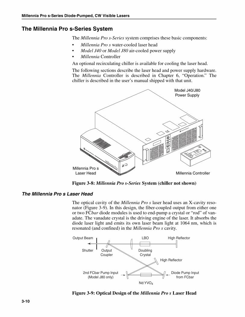
Millennia Pro s-Series Diode-Pumped, CW Visible Lasers
The Millennia Pro s-Series System
The Millennia Pro s-Series system comprises these basic components:
• Millennia Pro s water-cooled laser head• Model J40 or Model J80 air-cooled power supply• Millennia Controller
An optional recirculating chiller is available for cooling the laser head.
The following sections describe the laser head and power supply hardware.The Millennia Controller is described in Chapter 6, “Operation.” Thechiller is described in the user’s manual shipped with that unit.
Figure 3-8: Millennia Pro s-Series System (chiller not shown)
The Millennia Pro s Laser Head
The optical cavity of the Millennia Pro s laser head uses an X-cavity reso-nator (Figure 3-9). In this design, the fiber-coupled output from either oneor two FCbar diode modules is used to end-pump a crystal or “rod” of van-adate. The vanadate crystal is the driving engine of the laser. It absorbs thediode laser light and emits its own laser beam light at 1064 nm, which isresonated (and confined) in the Millennia Pro s cavity.
Figure 3-9: Optical Design of the Millennia Pro s Laser Head
Millennia Pro sLaser Head Millennia Controller
Spectra-Physics
LASER POWER
Setup
Info
||
||
Set: 2
.00W5.00LASER EMISSION
Model J40/J80Power Supply
Millennia Pro
AVOID EXPOSURE
AVOID EXPOSUREVISIBLE AND/OR
VISIBLE AND/OR
INVISIBLE LASER RADIATION
INVISIBLE LASER RADIATION
IS EMITTED FROM THIS APERTURE
IS EMITTED FROM THIS APERTURE
*SEE MANUAL
*SEE MANUAL
Laser Enable
Power
Laser Emission
Remote
Off / O
On / I
I
O
Nd:YVO4
Diode Pump Inputfrom FCbar
LBO High Reflector
DoublingCrystal
OutputCoupler
Shutter
Output Beam
High Reflector
2nd FCbar Pump Input(Model J80 only)
3-10

Laser Description
The vanadate crystal provides a very high small-signal CW gain, and iscapable of producing over 20 W of near diffraction-limited infrared powerwith a conversion efficiency of the light from the diode pump source ofgreater than 50%. The crystal is mounted on a structure (the “tower”) thatis thermally isolated from the laser head chassis.
The fiber-coupled FCbar design enables the astigmatic light from the diodemodules to be transformed to round beams of exceptional brightness thatare suitable for an efficient end-pumping geometry. In addition, by allow-ing the diode laser bar to be placed in the power supply, this designremoves its heat load from the laser head and facilitates the replacement ofthe diode laser in the field, because replacement does not require realign-ment of the laser cavity.
A telescope is used to focus the pump light through a dichroic fold mirrorand into the vanadate laser crystal. This dichroic mirror is highly transmis-sive at the diode pump laser wavelength and highly reflective at 1064 nm.
Frequency Doubling
Frequency-doubling converts the 1064 nm light from the laser crystal to thegreen 532 nm light that becomes the output of the laser.
A noncritically phase-matched lithium triborate (LBO) crystal placed inthe cavity converts the intracavity light to the green 532 nm wavelength.LBO offers a large acceptance angle, which makes it insensitive to anyslight misalignment of the Millennia Pro s cavity. A compact, low power,temperature-regulating oven is used to maintain the crystal at the appropri-ate phase-matching temperature to keep the 532 nm power optimized.
The patented Quiet Multi-Axial Mode Doubling (QMAD) technique pro-vides exceptionally low-noise performance. It uses a very large number ofaxial modes and balances gain, nonlinear conversion, and excited-state life-time to provide high power and extremely stable amplitude.
Virtually all the doubled light passes through the dichroic output couplerwhere the beam is then directed out of the laser. A beam splitter and photo-diode sample the output and provide feedback to the pump laser driver toprovide a constant output in power mode operation. A shutter placed out-side the cavity enclosure attenuates the beam until commanded to openeither by the Controller or via remote command.
A dichroic output coupler allows the 532 nm light to exit the cavity whilereflecting the 1064 nm light back into the cavity. The 90° polarization rota-tor aligns the polarization to the vertical axis required in many applications.
Light Pick-off and Power Control
A beam splitter near the output of the laser head samples a small portion ofthe green beam and directs it to the photodetector for the power controlfeedback circuit. Power mode is the standard operating mode for theMillennia Pro s; the control loop adjusts the diode pump current to keepthe power constant to within ± 1% of the set point.
3-11

Millennia Pro s-Series Diode-Pumped, CW Visible Lasers
The Model J40 and J80 Power Supplies
The Model J40 or J80 power supplies provide the diode laser pump lightthat powers the Millennia Pro s laser heads. They also contain the electricalpower and control circuitry for the system. The logic control hardware ishoused in the top section of the power supply. A thermo-electric cooler isused to cool the diode module(s).
The power supplies are air cooled and need no water or external coolingconnections. For electrical power they require a standard 110 or 220 Vac10 A power source. The power supplies can be mounted in a standard 19 in.rack. A power/control cable and fiber-optic cable(s) reside inside theumbilical that connects the laser head to the power supply.
The FCbar System
The pump source for the Millennia Pro s laser head is either a Model J40power supply that houses one 40 W diode laser bar, or a Model J80 thathouses two such bars. An integral optical fiber bundle transports the outputfrom the lasers in the diode bar to the laser head, where it is focused intothe end of the laser crystal. This diode laser module transport concept is the“fiber-coupled bar,” or FCbar™ technology that was discussed earlier.
FCbar technology enables the high power available from the lasers in thediode bar to efficiently end-pump the Nd:YVO4 laser crystal. To stabilizethe output wavelength of the diode lasers, the module is mounted directlyon a temperature regulated heatsink. Because the coupling technology is soefficient (85 to 90 percent of the diode laser light is available at the outputof the fiber bundle), the 40 W diode laser module can be significantly der-ated to increase its operating lifetime.
The FCbar module mates with the fiber bundle through precision connec-tions that are assembled and aligned at the factory. The bundle is then ter-minated at the laser head with an industry standard fiber-optic connector.This provides a precise and repeatable attachment of the bundle to the laserhead and allows an FCbar module to be replaced in the field, if necessary,without requiring an alignment of the cavity.
System Control
To turn the unit on and off and to provide operational control, the hand-heldMillennia Controller uses a simple, menu-driven interface. Chapter 6describes the Controller and its use in detail. The system can also be con-trolled via the standard RS-232 interface on the back of the power supplyby a user-written program of serial commands. Chapter 6 also provides alist of the serial commands available, and instructions on how to use theserial port.
The ProLite® diode laser packaged in the FCbar module in the powersupply is often referred to simply as the “diode” in the context of thismanual (e.g. the “diode current”).
Note
3-12
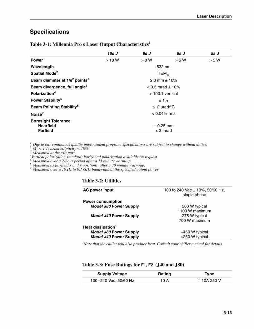
Laser Description
Specifications
Table 3-1: Millennia Pro s Laser Output Characteristics1
1 Due to our continuous quality improvement program, specifications are subject to change without notice.
10s J 8s J 6s J 5s J
Power > 10 W > 8 W > 6 W > 5 W
Wavelength 532 nm
Spatial Mode2
2 M2 < 1.1; beam ellipticity < 10%.
TEM00
Beam diameter at 1/e2 points3
3 Measured at the exit port.
2.3 mm ± 10%
Beam divergence, full angle3 < 0.5 mrad ± 10%
Polarization4
4Vertical polarization standard; horizontal polarization available on request.
> 100:1 vertical
Power Stability5
5 Measured over a 2-hour period after a 15 minute warm-up.
± 1%
Beam Pointing Stability6
6 Measured as far-field x and y positions, after a 30 minute warm-up.
≤ 2 µrad/°C
Noise7
7 Measured over a 10 Hz to 0.1 GHz bandwidth at the specified output power
< 0.04% rms
Boresight ToleranceNearfieldFarfield
± 0.25 mm< 3 mrad
Table 3-2: Utilities
AC power input 100 to 240 Vac ± 10%, 50/60 Hz,single phase
Power consumptionModel J80 Power Supply
Model J40 Power Supply
500 W typical1100 W maximum
275 W typical700 W maximum
Heat dissipation1
Model J80 Power SupplyModel J40 Power Supply
1Note that the chiller will also produce heat. Consult your chiller manual for details.
≈460 W typical≈250 W typical
Table 3-3: Fuse Ratings for F1, F2 (J40 and J80)
Supply Voltage Rating Type
100–240 Vac, 50/60 Hz 10 A T 10A 250 V
3-13

Millennia Pro s-Series Diode-Pumped, CW Visible Lasers
Chiller Specifications
The following requirements must be met by the chiller in order to properlycool the Millennia Pro s laser head. Refer to the manual provided with thechiller for its dimensions, specifications and utility requirements.
Table 3-4: Dimensions and Weights
Laser Headsize (w x h x d)
weightumbilical length1
(smallest static bend radius)
13.5 x 10.4 x 35.0 cm(5.3 x 4.1 x 14.0 in.)
10 kg (22 lb)4 m (13.1 ft)15 cm (6 in.)
Controllersize (w x h x d)
Controller cable length1
1 cable lengths are approximate
16.5 x 4.5 x 8.3 cm(6.5 x 1.75 x 3.25 in.)
2.5 m (8 ft)
Power Supply Model J40 Model J80
size (w x h x d)
weightair flowAC power cord length1
48.3 x 17.5 x 45.5 cm(19.0 x 6.9 x 17.9 in.)
25.0 kg (55 lb)2.8 m3/min (100 cfm)
2.5 m (8 ft)
48.3 x 17.5 x 45.5 cm(19.0 x 6.9 x 17.9 in.)
26.4 kg (58 lb)2.8 m3/min (100 cfm)
2.5 m (8 ft)
Table 3-5: Chiller Requirements
• The chiller should use distilled (not de-ionized) water.• The chiller should dissipate at least 100 W.• The chiller output must flow use a partial flow liquid filter of 10 mm or
smaller filter size.
water flow rate 0.5 liter/minute minimum2.0 liter/minute maximum
1.0 liter/minute recommended@ 180 kPa (26 psi)
water temperature 18 ±0.5°C (64.4 ±1.0°F)
pressure at the laser head inletminimummaximumrecommended
170 kPa (25 psi)310 kPa (45 psi
220 kPa-235 kPa (32-34 psi)
It is critical that the chiller meet the requirements for cooling the laserhead. Failure to do so will result in poor performance, and possiblydamage the laser. Such damage is not covered by the warranty.
Warning!
3-14

Laser Description
Outline Drawings
Figure 3-10: Outline Drawings for Laser Head, Controller and Power Supply
4.09(103,9)
2.34(59,4)
output end
All dimensions in inchesmm
6.50165,1
3.2582,6
1.7544,5
Controller side view
Controller top view
Spectra-Physics
LASER POWER
SetupInfo
|||| Set: 5.00W
5.00
LASER EMISSION
5.34(135,6)
12.00(304,8)
14.00(355,6)
7.42(188,5)
0.50(12,7)
2.00(50,8)
2.50(63,6)
1.19(30,2)
0.50(12,7)
4.00(101,6)
0.88(22,4)
1.03(26,2)
1.70(43,2)
beam center3 x 1/4 or 6 mm
Top Mount
3 x 8-32 Through
2 x 1/8 in. Locator Pins
2.09(53,1)
1.6040,6
6.80172,7
17.91454,9
19.00482,6
0.328,1
18.37466,6
6.80172,7
1.0326,2
0.5012,7
4.30109,2
6.63168,4
6.94176,3
3.98101,1
1.4937,8
Model J40/J80 side view
Laser Enable
Power
Laser Emission
Remote
Off / O
On / I
I
O
10–32 through x 3 (each side)Max. depth is 0.375 in.
Millennia Pro
Model J40/J80 front view
Millennia Pro s
bottom view
side view
3-15

Millennia Pro s-Series Diode-Pumped, CW Visible Lasers
Figure 3-11: Outline Drawing for Model KMC-100 Chiller
I 0
Thermo NESLABKMC 100
23.75603,3
6.63168,4
6.94176,3
Model KMC 100, Front Panel
Model KMC 100, Side Panel
19.00482,6
The chiller outline drawing shown above is for a typical chiller for theMillennia Pro s-Series system. Consult the chiller user’s manual for thespecifics for the chiller used with your system
Note
3-16

Chapter 4 Controls, Indicators and Connections
Introduction
This section defines the user controls, indicators and connections of theMillennia Pro s-Series system. It is divided into three sections: the MillenniaPro s laser head, the Millennia Controller and the Model J40/J80 power sup-ply. Information on the chiller can be found in the chiller user’s manual.
The Millennia Pro s Laser Head
Figure 4-1: The Millennia Pro s Laser Head
Internal Controls
There are no user-serviceable parts inside the Millennia Pro s laser head;no adjustment is required.
Legs
Legs (3)—(shipped with the Tsunami® when ordered) provide a means toset the laser beam to a height appropriate for pumping a Spectra-PhysicsTsunami oscillator. The legs are machined posts that screw into the 8–32holes on the 3 mounting pads located on the bottom of the laser head. Tableclamps are provided. There are no height adjustments.
Umbilical
MANUFACTURED:
MONTH
MODEL
YEAR
S/N
THIS LASER PRODUCT COMPLIES
WITH 21 CFR 1040 AS APPLICABLE.
Spectra-Physics Lasers, Inc.
1344 TERRA BELLA AVENUE
MT. VIEW, CALIFORNIA 94039
Millennia Pro
EmissionIndicator
AVOID EXPOSURE
AVOID EXPOSURE
VISIBLE AND/OR
VISIBLE AND/OR
INVISIBLE LASER RADIATION
INVISIBLE LASER RADIATION
IS EMITTED FROM THIS APERTURE
IS EMITTED FROM THIS APERTURE
*SEE M
ANUAL
*SEE M
ANUAL
0452-0150
*SEE MANUAL
VISIBLE AND
INVISIBLE*
LASER RADIATION
WHEN
OPEN. AVOID SKIN OR EYE
EXPOSURE TO DIRECT OR
SCATTERED RADIATION.
VISIB
LE AND/O
R INVIS
IBLE*
LASER RADIATIO
N
AVOID E
YE OR S
KIN E
XPOSURE TO
DIRECT O
R SCATTERED R
ADIATION
CLASS 4 LASER PRODUCT
532 NM
MAXIMUM O
UTPUT 15 W
EN 60825-1: 1994
*SEE M
ANUAL
4-1

Millennia Pro s-Series Diode-Pumped, CW Visible Lasers
Indicator
Laser emission indicator (white)— is off when there is no emission, andcomes on when the laser head is emitting or is capable of emitting laserlight (e.g. after depressing the ON button on the Millennia Controller for 3seconds).
Connections
Umbilical connector — connects the umbilical, which contains the fiber-optic cable(s) that provides pump laser energy to the laser head from thelaser diode module in the power supply. This umbilical is permanentlyattached to the power supply and laser head: do not try to remove it. Theumbilical also encloses the cooling water hoses from the chiller.
Control cable connector (26-pin D-sub) — connects the control cable tothe laser head from the power supply (from the LASER HEAD connector).
The Millennia Controller
Figure 4-2: The Millennia Controller
Controls
Seven buttons on the Controller operate the Millennia Pro s laser:
Select buttons (4)—are located to the left of the LCD screen and are usedto select one of four possible actions shown on the left side of the screen.For example, pressing the top left button brings up the Setup menu. Whenthe up/down arrows are shown on the screen, pressing the associated buttonscrolls the text.
LASER POWER button—performs 3 functions: (a) it begins the laserwarm-up cycle, (b) turns on the laser and (c) turns off the laser. (Note: thepower supply ac power must be on and the LASER ENABLE interlock key-switch set to ON in order for the laser to turn on).
Spectra-Physics
LASER POWER
SetupInfoP1P2
|||| Set: 10.00W
10.00
LASER EMISSION
SelectButtons (4)
Laser EmissionIndicator
LCDMonitor
LaserOn/Off
Up/Down Buttons (2)
4-2

Controls, Indicators and Connections
If the laser is in Standby mode, press the LASER POWER button once tobegin the warm-up cycle (otherwise, the rocker switch on the power supplystarts the warm-up cycle).
When the warm-up cycle completes, press and hold in the LASER POWERbutton for at least 3 seconds to turn on the laser. The red LASER EMISSIONon the Controller turns on and flashes while the button is held in. Followingthe 3 second CDRH delay, the laser head is capable of emitting radiation.
At this point, the LASER EMISSION indicator on the Controller stops flash-ing and stays on. The emission indicator on the laser head also comes on.Pins 2 and 3 on the Model J40 or J80 power supply EMISSION connectorclose to activate any user-installed indicator.
If the LASER POWER button is released before the 3 second delay is com-pleted, the sequence resets.
Up/down buttons—are located in the lower right corner of the panel, andincrease or decrease the value displayed on the screen (such as a power set-point), or allow the operator to select a parameter from a list to be changedor displayed.
Shutter—blocks the output beam when output is not requested. The shut-ter is controlled manually via the Setup menu on the Controller or via theSERIAL COM interface using the serial software (see Chapter 6).
Indicators
LCD monitor—provides feedback and control of the laser, depending onwhich menu is displayed. Large digits always display actual output power.Below the output power display, and shown in smaller text, is the outputpower setpoint. (“RS-232 Enabled” is shown if the system is being oper-ated remotely via the serial link).
LASER EMISSION indicator (red)—is off when there is no emission,flashes for 3 seconds prior to laser emission while the ON button isdepressed, then stays on when laser output is present.
Connections
There are no connectors on the Controller. The 2.5 m control cable is per-manently attached—do not try to remove it. The cable plugs into the 15-pin REMOTE connector on the front of the Model J40/J80 power supply.
4-3

Millennia Pro s-Series Diode-Pumped, CW Visible Lasers
The Model J40/J80 Power Supplies
This section defines the user controls, indicators and connections of theModel J40 or J80 power supply. These power supply models are air cooledwith one (Model J40) or two (Model J80) output fiber-optic cables on therear panel. Both versions have similar controls, indicators and connections.
The controls and indicators are located on the front panel, while connec-tions are on the rear panel.
The power supplies are autoranging and accept input from a 100 to240 Vac, 50 to 60 Hz single-phase source. The power supply is deliveredwith all necessary jumpers in place. The front and rear panels are describedbelow from left to right, top to bottom.
Front Panel
Figure 4-3: The Model J40 or J80 Power Supply Front Panel
LCD display—displays the status, including status codes, of the powersupply during boot-up and normal operation. During startup, this paneldisplays the status of the self-diagnostics program. If a problem occurs, allwarnings, including system operation errors, are displayed on this panel aswell as the control device.
LASER ENABLE interlock keyswitch—provides interlock safety to pre-vent unauthorized use of the laser when the key is turned to the OFF posi-tion and the key is removed. When the ac power switch is on and the key isturned to the ON position, the power supply performs an internal diagnosticcheck, and the laser head doubling crystal oven is allowed to warm up.Control then transfers to the Millennia Controller or to the host system (viathe RS-232 link), depending on your configuration.
Provide at least 6 inches of clearance from the front and back of theModel J40 or J80 power supply to allow cool air to enter the front andfor the heated exhaust air to exit the rear panel. Inadequate cooling willcause the system to overheat and shut down. Damage to componentscaused by insufficient cooling is not covered by the warranty.
Caution!
LCD Screen
LASER EMISSION Indicator
POWER Indicator REMOTE Connector
LASER ENABLE Interlock Keyswitch
On/Off AC Power Switch
Laser Enable
Power
Laser Emission
Remote
Off / O
On / I
I
O
4-4

Controls, Indicators and Connections
POWER indicator (yellow)—turns on immediately when line power isapplied to the system and the keyswitch is turned on.
LASER EMISSION indicator (green)—shows that power is supplied to thediode pump module(s), and that laser emission is present or imminent.
REMOTE connector (15-pin D-sub)—is used for controlling the laserlocally with the Millennia Controller.
AC power on/off switch—provides ac power to the Model J40 or J80power supply. See the description of the LASER ENABLE keyswitch formore information.
Air intake—allows cooling air to be drawn into the power supply. Theheated exhaust air is then vented from the rear panel.
Rear Panel
Figure 4-4: The Model J40/J80 Rear Panel
Fiber-optic cable(s)—is permanently attached to the diode module(s)inside the power supply and must be replaced along with the diode mod-ule(s). The clamping device on the panel provides strain relief for thecable(s) and must be removed prior to removing the diode module(s) fromthe system. The fiber-optic cable feeds into the umbilical.
Because the power supply must be on in order for the doubling oven toremain on, it is recommended that, to permit a short warm-up period,the AC POWER ON/OFF keyswitch be left in the ON position at all times(unless the system is going to be off for an extended period of time) andthat the Millennia Controller or RS-232 serial commands be used to turnthe system on and off.
If security is an issue, it is best to turn the power supply off and removethe key from the keyswitch.
Note
AC PowerInput
Fiber-Optic Cable(1 for J40, 2 for J80)
Fuse Chart
Fuses
Spectra-PhysicsSpectra-Physics Lasers, Inc.1330 Terra Bella Avenue, Mountain View, CA. 94043
MANUFACTUREDIN USA
MODEL S/N S240-827-NS1 521
AC Power
LINE VOLTAGE FREQUENCY
CAUTION: Double pole/neutral fusing
FUSES
FUSES
100 – 240 V~ 50/60 Hz T 10a
SERIAL COM AUXILIARYANALOG
LASER HEADINTERLOCKEMISSION
Emission Relay Safety Interlock
Analog Interface Serial InterfaceLaser
Head Interface
Aux. Interface
4-5

Millennia Pro s-Series Diode-Pumped, CW Visible Lasers
SERIAL COM connector (9-pin, D-sub)—provides for optional computercontrol of the system using the serial language described in Chapter 6,“Operation.” Refer to the pin descriptions in Table 4-1 and see “Serial Port”on page 4-7 for more information.
AUXILIARY connector — is not used on this system.
ANALOG connector (26-pin, D-sub)— is jumpered (the plug is shown inFigure 4-5) as it comes from the factory and is not used on theMillennia Pro s laser. The jumper plug must always be attached to the con-nector or the laser will not start, or will shut it off if it is already on.
Figure 4-5: The ANALOG Jumper Plug
EMISSION relay connector (3-pin AMP)—provides a relay that can beused to turn on and off a user-installed indicator that warns of the presenceof laser emission. See “Emission Connector” on page 4-7 for more infor-mation.
INTERLOCK connector (2-pin AMP)—provides attachment for a user-supplied safety switch. These contacts must be shorted together before thelaser will operate. A defeating jumper plug (Figure 4-6) is installed at thefactory to permit operation without a safety switch. See “Safety InterlockConnector” on page 4-8 for more information.
Figure 4-6: The INTERLOCK Jumper Plug
LASER HEAD connector (27-pin, D-sub)—provides attachment for thecontrol cable to the Millennia Pro s laser head.
AC POWER connector—provides attachment for the IEC-320-C13 powercord provided with the unit. Connect the cord to a standard power sourcecapable of providing single phase power between 100 and 240 Vac.
Air exhaust—these grills allow heated air to be expelled from the powersupply.
4-6

Controls, Indicators and Connections
Connector Interface Descriptions
Serial Port
Figure 4-7: The 9-Pin SERIAL COM Port
Emission Connector
This connection is used to turn on and off a user-installed external emissionindicator. When there is no laser emission, there is closure between the NCand C terminals and an open between the NO and C terminals. The oppositeis true when there is emission or emission is imminent. Refer to the circuitdiagram in Figure 4-8 below.
There is no power supplied by these terminals. This circuit is rated for30 Vac at 1 A. The mating connector is AMP part number 350766-1, whichuses male crimp pins, AMP part number 350218-1. The AMP pins aredesigned for specific wire gauges, so choose the appropriate wire. Otherconnectors will fit these jacks, including solder-cup and “IDC” style con-nectors.
Table 4-1: IBM-PC/AT Serial Port Pinout
Computer or Terminal Model J40 or J80
RS-232-CSignal Name
Signal Pin No.(25-Pin)
Pin No.(9-Pin)
Pin No. Signal
Transmit Data TXD 2 3 3 RXD
Receive Data RXD 3 2 2 TXD
Not Connected RTS 4 7 – CTS
Not Connected CTS 5 8 – RTS
Not Connected DSR 6 6 – DTR
Not Connected DCD 8 1 – DCD
Not Connected DTR 20 4 – DSR
Signal Ground 7 5 5
Protective Ground 1 SHELL SHELL
Pin # Description
3 Common (C)
2 Normally Open (NO)
1 Normally Closed (NC)
1 5
6 9
4-7

Millennia Pro s-Series Diode-Pumped, CW Visible Lasers
Figure 4-8: The Model J40 or J80 Emission Connector Circuit
Safety Interlock Connector
This is a system interlock that must be closed for operation. The plug pro-vided with the system can be replaced with a connector that is wired toauxiliary safety equipment (such as a door switch) to shut off the laserwhen actuated (opened).
Such a switch must be designed for a 12 V 100 mA signal. The mating con-nector is AMP part number 350777-1, which uses female crimp pins, AMPpart number 350536-1. The AMP pins are designed for specific wiregauges, so choose the appropriate wire. Other connectors will fit thesejacks, including solder-cup and “IDC” style connectors.
Pin # Description
1 System Interlock
2 System Interlock Return
EMISSION
J3
EMISSION
K1
+ 24 V
N10
3 C2 NO1 NC 1
105
3
8
3 2 1C NO NC
4-8

Chapter 5 Installation
This section provides detailed instructions and information for planning theinitial setup of the Millennia® Pro s-Series system. If you have not set upthe system before, or you are moving it to a new location, please reviewthis section in detail.
When you received your laser, it was packed with the laser head and powersupply already connected. Do not disconnect the umbilical cables fromeither end!
System Installation Considerations
Be sure to follow all safety precautions for laser use while handling or stor-ing the laser. Be sure to install all laser safety devices before using the laser.Refer to the Chapter 2, “Laser Safety” for more information on this topic.
Except for a small screwdriver, all the tools and equipment needed to set upthe Millennia Pro s laser are in the accessory kit.
The laser head is fastened to the mounting surface using the clamps, screwsand nested spherical washers provided with the system. The clamps can beused on optical tables with either metric spacing or English hole spacing.
The power supply, chiller, and laser head together produce less than 1500 W(5 kBTU per hour) of waste heat for models using the Model J80 powersupply, or less than 850 W (2.9 kBTU per hour) for models using theModel J40. Provide enough cooling capacity to prevent room over-heating.
The fiber-optic cable(s) in the umbilical has a minimum bend radius of6 in. (15 cm). Consider both the minimum bend radius and strain relief asyou route the umbilical from the power supply to the laser head.
The installation procedures in this chapter are not intended for the initialinstallation of your laser. Please call your Spectra-Physics servicerepresentative to arrange an installation appointment, which is part ofyour purchase agreement. Allow only personnel authorized by Spectra-Physics to install and adjust your laser. You will be charged for repair ofany damage incurred if you attempt to install the laser yourself, andsuch action might also void your warranty.
Warning!
Do not twist or bend the umbilical to a radius of less than 6 in. (15 cm).Doing so can damage the fibers inside. Such damage is not covered byyour warranty.
Warning!
5-1

Millennia Pro s-Series Diode-Pumped, CW Visible Lasers
Mounting the Laser Head
The laser head arrives with the control cable already connected to the headand held in place by a bracket. The laser head is permanently connected tothe power supply by the umbilical. Move both units to a stable locationwithin 4 m (the length of the umbilical) of where the laser is to be installed.
The laser head should be secured to an optical table or other flat mountingsurface. Three slots are provided in the bottom edge of the mounting basefor this purpose, two near the output bezel and one at the center rear. Alsosupplied are three laser head clamps that can be used on an optical tablewith either metric hole spacing (175 mm) or English (1 in.) spacing.
1. If the Millennia Pro s is going to be used to pump a Spectra-PhysicsTsunami® laser, screw the 3 legs included in the Tsunami accessory kitinto the holes shown in Figure 5-1 until they are secure. The 3.5 in.legs raise the laser off the table to a beam height of approximately5.8 in. (14.8 cm).
Figure 5-1: Location of leg mounting holes on the bottom of the laserhead. The second set of holes are for OEM use only.
2. Secure the laser head to the table.
a. If the laser is to be mounted directly to the table (no legs), insertthe three laser head clamps (provided) into the slots in the mount-ing base as shown in Figure 5-2. Then, using table mountingscrews along with the nested spherical washers (also provided),fasten the laser to the table via the desired mounting holes.
If you are installing the power supply in a standard rack, first follow theinstructions later in this chapter for installing the power supply beforemounting the laser head.
Note
Do not use the holes on the bottom plate of the laser head to mount theMillennia Pro s laser.
Note
#8-32 Leg Mounting Holes
¼ in. Holes for OEM Top Mounting
Front Rear
5-2

Installation
b. If legs are used to raise the laser head off the table, clamp them inplace with the 3 foot-clamps provided with the legs. Slide a U-shaped end over the foot of each leg, place a table mounting screwthrough the slot and fasten the leg to the table.
Figure 5-2: Laser head mounting clamps and base slots
Mounting the Chiller and Power Supply
There are three ways to position the chiller and power supply:
• If the system includes a floor-standing chiller on rollers, refer to“Mounting the Power Supply and Chiller as Stand-Alone Units”below.
• If the system includes a rack-mountable chiller (such as the Thermo-NesLab Model KMC-100 and optional rack kit), refer to “Mountingthe Power Supply and Chiller in the Optional Rack” below.
• If the components are to be mounted in a standard enclosed rack, see“Mounting the Power Supply and Chiller in a Standard Rack” below.
Although the rack-mountable Model J40 or J80 power supply and theModel KMC-100 chiller do not need to be rack-mounted, we recommendmounting them in the optional open-air, 19-inch rack to save lab space.Once mounted, this entire unit can be rolled out of the way under a table.
VISIBLE AND
INVISIBLE*
LASER RADIATION
WHEN
OPEN. AVOID SKIN OR EYE
EXPOSURE TO DIRECT OR
SCATTERED RADIATION.
2 FrontClamps
Slots in basefor clamps
Cap headscrew and
nested sphericalwashers
1 RearClamp
Millennia Pro
AVOID EXPOSURE
AVOID EXPOSURE
VISIBLE AND/OR
VISIBLE AND/OR
INVISIBLE LASER RADIATION
INVISIBLE LASER RADIATION
IS EMITTED FROM THIS APERTURE
IS EMITTED FROM THIS APERTURE
*SEE M
ANUAL
*SEE M
ANUAL
0452-0150
VISIB
LE AND/O
R INVIS
IBLE*
LASER RADIATIO
N
AVOID E
YE OR S
KIN E
XPOSURE TO
DIRECT O
R SCATTERED R
ADIATION
CLASS 4 LASER PRODUCT
532 NM
MAXIMUM O
UTPUT 15 W
MANUFACTURED:
MONTH
MODEL
YEAR
S/N
THIS LASER PRODUCT COMPLIES
WITH 21 CFR 1040 AS APPLICABLE.
Spectra-Physics Lasers, Inc.
1344 TERRA BELLA AVENUE
MT. VIEW, CALIFORNIA 94039
Provide at least 6 inches of clearance from the front and back of thepower supply to allow cool air to enter the front and for the heatedexhaust air to exit the rear panel. Inadequate cooling will cause thesystem to overheat and shut down. Damage to components caused byinsufficient cooling is not covered by the warranty.
Caution!
5-3

Millennia Pro s-Series Diode-Pumped, CW Visible Lasers
Mounting the Power Supply and Chiller as Stand-Alone Units
Place the power supply in a convenient location within 4 m of the laserhead (the length of the umbilical), and place the floor-standing chillernearby. Be careful that the heat generated by the power supply and chillerdoes not adversely affect the laser.
Ensure that the electrical cables and umbilical are safely routed and notunder any strain or compression. Avoid conditions where the cables can bestepped on. Use caution when moving the power supply to prevent damageto the fiber-optic cable. Do not step on or roll objects over the umbilical.
Mounting the Power Supply and Chiller in a Standard Rack
The following describes the procedure for installing the power supply intoa standard 19 in. (48.3 cm) enclosed rack. The laser head and power supplyare permanently connected via the umbilical. Therefore, three people areneeded to install the power supply into an enclosed rack.
Place the rack in a convenient location less than 4 m (the length of theumbilical) from where the laser head will be located.
Install the chiller in the rack first. Determine the support for the chiller inthe rack, then use two people to safely lift the chiller and slide it into therack and onto the support surface. Use screws to fasten the chiller frontpanel to the rack.
Next, install the power supply in the rack. With one person holding thelaser head, two people should carefully lift the power supply. The personwith the laser head can now pass it through the rack from the front and outthe back. The people holding the power supply can now slide it into therack and onto the support structure.
Be careful that the heat generated by the power supply will not adverselyaffect the laser. Provide filtered ventilation air so that it flows into the bot-tom of the rack enclosure, past the power supply without obstruction, andexhausts from the top. Do not add shelves between units or over-heatingwill result.
Fasten the front panel of the power supply to the rack using four screws.
Install the laser head following the procedures listed earlier.
Caution! The chiller must be mounted in the lowest slot in the rack so that anyleak or condensation will not drip onto equipment below it.
Caution! The four screws used to mount both the chiller and the power supply areonly meant to secure them in place, not to support them. Provide slidesor rails to support the weight of these units. Mounting holes areprovided on the side of the power supply for attaching slides. Refer to“Outline Drawings” on page 3-15 for hole locations and sizes.
5-4

Installation
Mounting the Power Supply and Chiller in the Optional Rack
The optional rack is shipped along with the system in a separate box. Itconsists of two parts, the rack base with 4 lockable casters pre-installed,and a vertical rack component that mounts to one end of the base. The rackprovides room for mounting two 7-inch rack panels, such as the power sup-ply and chiller.
Holes for rail support are provided along the sides of the power supply(refer to “Outline Drawings” on page 3-15 for dimensions and hole loca-tions). The rack-mountable chiller must be supported from the bottom. Themounting holes on the front panels are for locking these units into the rack,not for supporting them.
Please read these instructions completely before beginning the installation.
1. When installing the power supply, to prevent the laser head from beingpulled off the table by the umbilical, place it on the floor or, alterna-tively, secure it in place on a table or other mounting surface (refer to“Mounting the Laser Head” above.)
2. Remove the bubble pack from both rack components, taking care notto scratch the coated surfaces.
3. Place the rack base on the floor. Note the end of the base that has anotch in each corner (Figure 5-3), then set the chiller on the base sothat its front panel faces the notched end (Figure 5-4) and sticks outover the end. Next, place the power supply on top of the chiller andalign their front panels (Figure 5-5). The chiller must be on the bot-tom to prevent damage caused by any leaks or condensation.
Figure 5-3: The mounting rail notch on the rack base. The mountingbolt for the vertical rack engages the slot to the right.
5-5

Millennia Pro s-Series Diode-Pumped, CW Visible Lasers
Figure 5-4: The chiller shown set on the base facing the two notches(away from the camera).
Figure 5-5: The chiller and a power supply shown set on the base.
5-6

Installation
4. Attach the vertical rack to the notched end of the base.
a. Loosen the T-shaped locking bolt and its nut (Figure 5-6) on eachend of the rack (loosen the nut to the end of the threads, but keep itattached). Orient the bolts to the slots in the base (Figure 5-3).
Figure 5-6: One end of the vertical rack showing the locking bolt(upper bolt).
b. Drop the rack into place so that the locking bolts engage the slots.There has to be enough free play for the bolt to extend completelydown into the slot and turn 90 degrees.
c. Align the front of the rack to the base.
d. Tighten the locking nuts to 18 lb/ft.
Tightening the locking nut automatically turns the T-bolt 90degrees inside the slot to its locking position, then pulls the racktight to the base. Loosening the nut does just the opposite; itrealigns the bolt with the slot for easy removal.
Figure 5-7 shows the fully assembled unit before the power supply andchiller panels are secured to the rack.
Figure 5-7: The power supply and chiller on the rack.
5. Using the 8 mounting screws from the system accessory kit, secure thechiller and power supply to the rack.
5-7

Millennia Pro s-Series Diode-Pumped, CW Visible Lasers
Connecting the System
Refer to interconnect drawing Figure 5-8.
Figure 5-8: Interconnect Drawing, Millennia Pro s
1. Set the Millennia Controller or the computer in a convenient location.
2. The system arrives with the control cable connected to the laser head.Connect the free end of the control cable to the 27-pin D-sub LASERHEAD connector located on the power supply (see Figure 5-9).
Figure 5-9: The rear panel of the Model J40/J80 power supply
3. The two pins of the INTERLOCK connector on the rear panel of the powersupply must be jumpered or connected to an external, closed safetyswitch or the laser will not turn on. To use the INTERLOCK safetyswitch, refer to the detailed description of this circuit in Chapter 4 inthe section “Connector Interface Descriptions.”
ChillerModel J40 or J80
Power Supply
ComputerControl Source
Millennia Pro sLaser Head
"Serial Com"RS-232
Connection
MillenniaController"Remote"
Connection
PowerCord
or
100 – 240 Vac50/60 Hz
optionalEmissionIndicator
optionalSafety
Interlock
PowerCord
CoolingWaterHoses
Umbilical
Laser HeadControl
Fiber-OpticCable
AC PowerInput
Fiber-OpticCable
Fuse Chart
Fuses Emission Relay Safety InterlockAnalog Interface Serial Interface Laser Head
Aux. Interface
Spectra-PhysicsSpectra-Physics Lasers, Inc.1330 Terra Bella Avenue, Mountain View, CA. 94043
MANUFACTUREDIN USA
MODEL S/N S240-827-NS1 521
AC Power
LINE VOLTAGE FREQUENCY
CAUTION: Double pole/neutral fusing
FUSES
FUSES
100 – 240 V~ 50/60 Hz T 10a
SERIAL COM AUXILIARYANALOG
LASER HEADINTERLOCKEMISSION
Fiber-Optic Cable(Model J80 only)
5-8

Installation
If you are not going to employ a safety switch, the 2-pin jumper plug(P/N 0129-3815) should be inserted into the INTERLOCK connector(see Figure 5-9).
4. Verify that the 26-pin ANALOG connector next to the fiber-optic cable(see Figure 5-9) contains a jumper plug (P/N 0129-4024).
5. Attach the control device.
a. If you ordered your system to be configured at the factory for con-trol via the SERIAL COM port only, skip to step c.
b. Connect the Millennia Controller cable from the Controller to the15-pin REMOTE connector on the front of the power supply. Ifnecessary, remove the jumper plug from the connector and store itin a safe place.
c. If you are using serial commands to control the laser system, attacha standard 9-pin serial control cable (not provided) between theserial port of your host controller (typically a PC computer) andthe RS-232 connection on the power supply rear panel.
Refer to Chapter 4, “Controls, Indicators and Connections”for pindescriptions. Also refer to “Controlling the System Using theSERIAL COM Interface” on page 6-14.
If the system is to be operated solely by the computer and not bythe Millennia Controller, the REMOTE jumper plug must beplugged into the connector on the front panel.
Figure 5-10: The REMOTE connector on the power supply front panel
6. If an emission indicator lamp is required, in addition to those on thelaser head and the power supply front panel, use the EMISSION relayconnector (Figure 5-9) on the rear panel of the power supply to turn alamp on and off. To use the EMISSION relay, refer to the detaileddescription of this circuit in Chapter 4 in the section “Connector Inter-face Descriptions.”
7. Attach the provided IEC power cord to the power connector on thepower supply and fasten it to the receptacle retaining screws so that itdoes not pull out. Plug the other end into a facility power outlet thatcan supply 100 to 240 Vac, 15 A single phase power.
Laser Enable
Power
Laser Emission
Remote
Off / O
On / I
I
O
Remote Connector
5-9

Millennia Pro s-Series Diode-Pumped, CW Visible Lasers
A Schuko type plug is provided to European countries. If you receiveda plug inappropriate for your area, call your Spectra-Physics regionaldistribution center to obtain one (refer to Chapter 8, “CustomerService,” for telephone numbers).
8. Verify that the correct fuses are in place for the power supply. Refer to“Specifications” on page 3-13.
Connecting the Chiller
Refer to the user’s manual that came with the chiller for detailed informa-tion on installing and starting it.
1. Mount the chiller on the floor, table top or in a rack close enough to thepower supply so that the cooling hoses from the umbilical can reachthe connections on the back of the chiller. Refer to “Mounting theChiller and Power Supply” above.
2. Screw both hoses onto the chiller and tighten.
The hose connections are not polarized. Finger tight is enough: do notovertighten.
3. Verify there is water in the chiller, then turn on the chiller. Verify wateris flowing and that there are no leaks at the hose connections.
4. Set the chiller temperature for 18°C (64.4°F).
This completes the installation of the Millennia Pro s-Series system.
Moving the System
To move the system:
Rack-mounted systems—place the laser head and Controller on top of thepower supply or rack and roll the system to its new location.
Non-rack-mounted systems—disconnect the chiller supply lines at thechiller and drain the lines. Then set the chiller and power supply on a cartand the laser head and Controller on top of the power supply, then roll theentire system to its new location. Make sure the cooling lines are recon-nected and tightly fastened to the chiller before restarting the laser aftermoving it.
Alignment
There is no alignment procedure for the Millennia Pro s-Series system:there are no knobs to adjust or optics to change.
When you are ready to turn on the laser, refer to Chapter 6, “Operation.”
Do not place the chiller above the laser. If the unit develops a leak orcondensation forms, dripping water may damage the laser or otherobjects below it.
Warning!
5-10

Chapter 6 Operation
Please read this entire chapter and Chapter 2 on laser safety before usingyour laser for the first time. This chapter contains information for operatingthe laser system locally, using the Millennia Controller, or remotely, usinga computer and the system commands explained later in this chapter.
After your Millennia Pro s has been installed, we strongly suggest leavingthe power supply power switch in the “on” position at all times. Doing sodrastically reduces the warm-up time by keeping the SHG doubling crystaloven on, and it will help protect the crystal, especially in humid environ-ments.
Using the Millennia Controller
The Millennia Controller (Figure 6-1) is a convenient device for operatingthe Millennia Pro s laser locally.
Figure 6-1: The Millennia Controller
The Spectra-Physics Millennia® Pro s laser is a Class IV—High PowerLaser whose beam is, by definition, a safety and fire hazard. Take pre-cautions to prevent accidental exposure to both direct and reflectedbeams. Diffuse as well as specular beam reflections can cause severeeye or skin damage.
Danger!Laser Radiation
EyewearRequired
Spectra-Physics
LASER POWER
SetupInfoP1P2
|||| Set: 10.00W
10.00
LASER EMISSION
SelectButtons (4)
Laser EmissionIndicator
LCDMonitor
LaserOn/Off
Up/Down Buttons (2)
6-1

Millennia Pro s-Series Diode-Pumped, CW Visible Lasers
Use the four buttons on the left side of the Controller to select one of thefour possible options shown on the left side of the screen. For example,press the top left button to go to the Setup menu or the next button down togo to the Info menu, etc. Not all menus use all of the buttons.
The LASER POWER button turns the laser on and off.
The up/down buttons in the lower right corner either increase or decreasethe value displayed on the screen (such as the power setpoint), or allow theselection or change of a parameter from a list on the display.
What is shown on the screen depends on the menu selected. The large dig-its always display actual output power, and below that in smaller text is theoutput power setpoint. “RS-232 Enabled” is displayed if the system is setfor remote operation via the serial link.
The function of each menu is summarized in the following list. The use ofthe Controller to select and perform these functions is described in the nextsection.
• Use the Main menu to monitor laser output power and to set the poweroutput level.
The Main menu displays a status message indicating if the system isunder remote control (serial commands for remote control of the laserby a computer are listed at the end of this chapter).
• Use the Setup menu to open and close the shutter and to run the SHGcrystal optimization routine. The Setup menu also lets you activate ordeactivate Standby mode and to set the time delay before Standby isactivated. Main menu power setpoints P1 and P2 are also set using theSetup menu.
The Setup menu is accessed from the Main menu.
• Use the Info menu to view the pump diode current level, thetemperature of the diode pump laser, the temperature status of theSHG doubling crystal (“warming” or “stable”) and the revisionnumbers for the Millennia software. Also included is a history (HST)line that shows the last three system status codes.
The Info menu is accessed from the Main menu.
• The Standby menu is displayed anytime the power supply is left on butthere has been no laser emission for a time greater than the standbydelay time setting.
The Standby menu is accessed from the Setup menu.
• The Warm-up menu is displayed after the system is powered up from acold start (i.e., the power supply was turned off after the last time itwas used). It allows the operator to monitor the warm-up process.
Each of the menus is described in greater detail below.
6-2

Operation
The Menu System
Four menus—Main, Setup, Standby, and Information—are used to controland monitor the system. Sample menu displays are shown in Figure 6-2.
Figure 6-2: The Millennia Pro s Menus
The upper left-hand frame shows the warm-up menu that is displayed soonafter the system is powered up from a cold start (i.e., the power supply wasturned off after the last time it was used). It allows the operator to monitorthe warm-up process, which takes about 35 minutes. If the system is beingcontrolled remotely using the serial interface, a query command allows theoperator to monitor the warm-up process (refer to the “Queries” sectionlater in this chapter).
The Standby menu is displayed anytime the power supply is left on butthere has been no laser emission for a time greater than the Standby Delaytime setting.
The Main, Setup, Standby, and Info menus are further described in the fol-lowing sections.
The Main Menu
When the system is ready for operation following the warm-up sequence,the Main menu is displayed. From here the operator can set the outputpower and monitor system performance. The large numbers indicate actualoutput power; the smaller numbers below it indicate either the power set-point (the desired output power) or “RS-232 Enabled” when the system isset to operate remotely via the SERIAL COM port.
Power mode (with the laser system in local control) is displayed in the fig-ure below. When the system is tracking properly, actual output power andsetpoint are the same, ± 0.01 W.
Main ||||
Shutter: Open
*** INFO ***
D1: 19.5 Amps ⇓
SetupInfoP1P2
P1P2
|||| Set: 0.05W
0.05
Main ||||
→Shutter: Open←Mode: Power
*** SETUP ***
SetupInfo
|||| RS232 enabled
10.00
SetupInfo
||||
Warming Up System
SetupInfo
||||
key to warm up
––STANDBY––
Main Menu: Power Monitor
Information Menu
Warm-up Menu Setup Menu: Mode Select
Main Menu: RS-232 "Enabled" Display
Standby Menu
80%
Press "POWER"
6-3

Millennia Pro s-Series Diode-Pumped, CW Visible Lasers
To change the power setpoint, either press one of the preset power setpointkeys (P1 or P2) to move directly to a power previously set in the Setupmenu, or use the up/down buttons to set a new value. Note that when theup/down buttons are held in, the setpoint numerical update pauses fromtime to time. This is normal.
If an error occurs, “Error” flashes in the lower left corner of the Mainmenu. To display the source of the error, press the lower left button (statuscodes and their definitions are listed in Appendix A.) When the problem iscorrected, the error message turns off. If the error code is generated by thepower supply, it is logged on the history (HST) line in the Info menu.
Menus available from the Main menu are Setup and Info.
The Setup Menu
Use the Setup menu to:
• open and close the shutter,• run the SHG optimization routine,• activate or deactivate Standby mode,• set the time delay before Standby is activated, and• set the Main menu preset power values for P1 and P2.
To access this menu from the Main menu, use the two lower left buttons toscroll the menu up and down. The selected item is the one between the hor-izontal arrows (the example screen above shows the shutter status, whichcan be set to open or close). To change the value for the selected item, usethe up/down buttons to the right of the screen.
Selections include:
• Shutter: Open, Closed• Mode: Power, SHG Opt, RS-232• Stdby: 15 min, 30 min, 1 hour, 4 hours, Never• P1 Set: any value between 0.05 W and the maximum• P2 Set: any value between 0.05 W and the maximum
SetupInfoP1P2
|||| Set: 0.05W
0.05
Main ||||
→Shutter: Open←Mode: Power
*** SETUP ***
Changes are activated upon return to the Main menu.Note
6-4

Operation
Shutter
The shutter, when closed, mechanically blocks the laser beam.
Modes
Power mode adjusts the pump diode laser current as necessary to maintainconstant output power. It is the normal method of operating the laser.
To provide optimum conversion efficiency, the SHG optimization routine(“SHG Opt”) automatically optimizes the temperature of the LBO dou-bling crystal, thereby optimizing the efficiency of second harmonic conver-sion. Maintaining the optimum conversion efficiency will minimize theamount of pump diode laser current needed to reach the specified outputpower. The SHG Opt routine is typically run at installation, and should notneed to be run again unless the ambient environment has changed signifi-cantly. The routine takes about 15 minutes to complete.
Under certain conditions, small manual adjustments to the SHG tempera-ture may be required to maintain peak performance. This capability is pro-vided through a selection on the SHG display.
The Setup menu also indicates when control of the laser via commandsfrom a host computer or similar device has been established. When serialcontrol is activated, “RS-232 Enabled” is displayed on the Main menu, andthe laser can be controlled in parallel by commands from either the hostcomputer or the Millennia Controller.
Instructions for establishing a remote connection are provided later in“Controlling the System Using the SERIAL COM Interface” on page 6-14.The software commands for serial control are explained later under “TheCommand/Query Language” on page 6-15.
Stdby
Standby (“Stdby”), when active, causes an automatic system power downwhenever the power supply is left on but no laser emission has been presentfor a time greater than the “Stdby Delay” time setting. This is the preferredoff condition for day-to-day operation.
Standby can be defeated by setting the delay time to “Never.”
P1, P2 Set
P1 SET and P2 SET allow the user to preset two power levels that can beselected from the Main menu during operation by pressing one of the twolower left buttons on that screen. See the Main menu description above.
Pressing the Main button from the Setup menu activates the values justselected and then displays the Main menu.
Current mode operation is not available on the Millennia Pro s-Series.Note
6-5

Millennia Pro s-Series Diode-Pumped, CW Visible Lasers
The Standby Menu
Once Standby mode is activated via the Setup menu, the Standby menuautomatically displays whenever the Model J40 or J80 power supply is onbut laser emission is off for more than the pre-set time (the “Stdby Delay”time—see the Setup menu). This is the recommended, over-night “off”condition. Refer to “Turning On the Laser, Warm Start” and “Turning Offthe Laser” later in this chapter.
This display is not shown when the system is started cold—that is, whenthe power supply has been turned off; it can only be accessed from theSetup menu.
The Info Menu
The Info (“information”) menu shows whether the shutter is open orclosed, and provides diagnostic information on the diode laser(s) and theSHG doubling crystal. It contains a history (HST) line that displays thethree most recent system status codes. The codes and their definitions arelisted in Appendix A. The Info menu is accessed from the Main menu.
Use the select buttons on the left side of the Controller (not the up/downbuttons on the right side) to scroll the screen – note the down arrow in thefigure above. Two lines or three are displayed at a time as follows, from topto bottom:
• Status of the shutter (open/closed)Example: Shutter: Open
• Drive current for the diode laser D1
Example: D1: 19.9A
• Temperature of diode D1, degrees CelsiusExample: D1: 19.5C
• History buffer —last three status codesExample: HST: 001 003 005
SetupInfo
||||
key to warm up
––STANDBY––Press "POWER"
Main ||||
Shutter: Open
*** INFO ***
D1 :19.5 Amps ⇓
For systems that employ two diode modules, the status of the seconddiode laser will be listed following the status of the first, where applica-ble (e.g. D2: 20.6Amps).
Note
6-6

Operation
• Status of the SHG doubling crystal temperature status(Stable is displayed when the proper temperature is reached.)
Example: SHG: Stable
• Tower temperature, degrees CelsiusExample: TWR: 22.2C
• Diode hours—total time the diode has been usedExample: D1: 11.2hrs
• Diode initial current (original factory setting)Example: D1Icur: 36.7A
• Diode initial temperature (original factory setting)Example: D1Itmp: 23.0C
• Diode module serial number(s)Example: D1serial# xxxxxxxxxxxxxxx
• Present SHG setting (coarse/fine)Example: SHG: +3088/8
• Millennia system typeExample: IDN Mil Pro 5sJ
• Millennia software revision(Have this revision number available whenever calling for service.)
Example: PS: 0456-9100C
• Controller firmware revisionExample: Rmt: 6.04
Pressing the “Main” button returns the display to the Main menu.
System Startup/Shutdown
There are two turn-on sequences. The cold start turn-on sequence is usedwhen the system starts with the power supply turned off. The warm startsequence is used when the system is in Standby mode (when the laser is offbut the power supply has been left on).
Turning On the Laser, Cold Start
1. Verify all connectors are plugged into the power supply and laser head(they should never be disconnected—if they have been, refer to Chap-ter 5, “Installation,” for instructions on re-connecting them).
2. Turn on the power supply ac power switch.
3. Turn on the chiller. Verify it is set to 18°C.
Refer to the chiller user’s manual for instructions on setting the tem-perature.
4. Turn on the power supply keyswitch.
When Standby mode is activated, the system automatically powersdown after the preset delay time, and the Standby menu is displayed. Torestart the unit, follow the procedure for a warm start turn-on.
Note
6-7
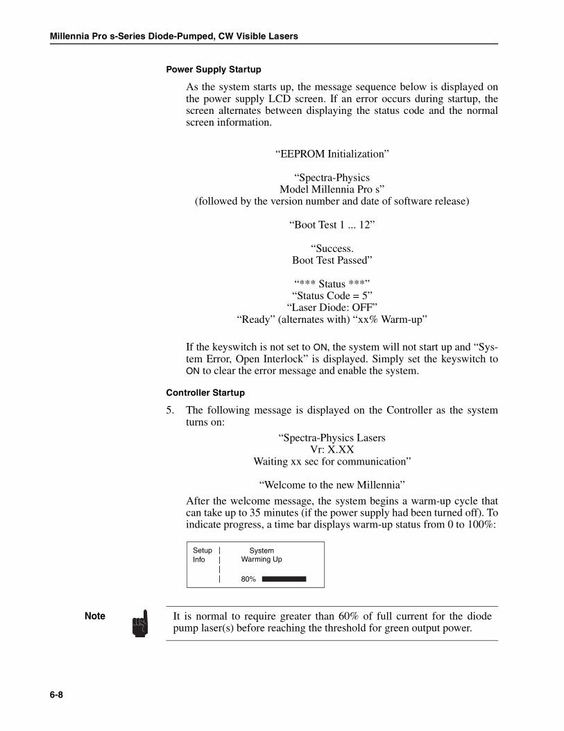
Millennia Pro s-Series Diode-Pumped, CW Visible Lasers
Power Supply Startup
As the system starts up, the message sequence below is displayed onthe power supply LCD screen. If an error occurs during startup, thescreen alternates between displaying the status code and the normalscreen information.
“EEPROM Initialization”
“Spectra-PhysicsModel Millennia Pro s”
(followed by the version number and date of software release)
“Boot Test 1 ... 12”
“Success.Boot Test Passed”
“*** Status ***”“Status Code = 5”
“Laser Diode: OFF”“Ready” (alternates with) “xx% Warm-up”
If the keyswitch is not set to ON, the system will not start up and “Sys-tem Error, Open Interlock” is displayed. Simply set the keyswitch toON to clear the error message and enable the system.
Controller Startup
5. The following message is displayed on the Controller as the systemturns on:
“Spectra-Physics LasersVr: X.XX
Waiting xx sec for communication”
“Welcome to the new Millennia”
After the welcome message, the system begins a warm-up cycle thatcan take up to 35 minutes (if the power supply had been turned off). Toindicate progress, a time bar displays warm-up status from 0 to 100%:
SetupInfo
||||
Warming Up System
80%
It is normal to require greater than 60% of full current for the diodepump laser(s) before reaching the threshold for green output power.
Note
6-8

Operation
6. When the system has warmed up, the following screen is displayed:
Press and hold in the LASER POWER button until the laser starts. Whenthe button is pressed, the LASER EMISSION light on the Controllerflashes for a few seconds. Then, when laser emission occurs, theLASER EMISSION light stops flashing and remains on, and radiation isavailable when the shutter is opened.
At this point, the Main menu is displayed and output power ramps upslowly to 0.05 W.
7. Use the Setup menu to open the shutter.
If the shutter is closed, no emission will occur until it is opened via theSetup menu or through software.
8. From the Main menu, set laser output power using the up/down but-tons or by pressing the P1 or P2 button. Actual output power will fol-low the setpoint value.
This completes the cold start procedure. The system is now ready for use.
Turning On the Laser, Warm Start
This procedure assumes the unit was left in Standby mode after it was lastused. When this is the case, the following Standby prompt is displayed.
1. Check that the chiller is on and set it for 18°C.
2. Press the LASER POWER button to begin the short warm-up cycle.
The following prompt is displayed for about 2 minutes while the diodemodule temperature stabilizes:
SetupInfo
|||| Set: 0.05W
Hold "POWER"key to turn on
SetupInfoP1P2
|||| Set: 0.05W
0.05
SetupInfo
||||
key to warm up
––STANDBY––Press "POWER"
SetupInfo
||||
STABIZINGDiode Tempertature
It is normal to require greater than 60% of full current for the diodepump laser(s) before reaching the threshold for green output power.
Note
6-9

Millennia Pro s-Series Diode-Pumped, CW Visible Lasers
3. When the system has warmed up, the following screen is displayed:
Press and hold in the LASER POWER button until the laser starts. Whenthe button is pressed, the LASER EMISSION light on the Controllerflashes for a few seconds. Then, when laser emission occurs, theLASER EMISSION light stops flashing and remains on, and radiation isavailable when the shutter is opened. (The shutter will be in the sameposition it was in when the system went into Standby.)
At this point, the Main menu is displayed and output power ramps upto the previously set power level.
4. Use the Setup menu to open the shutter.
5. From the Main menu, set laser output power using the up/down but-tons or by pressing the P1 or P2 button. Actual output power will fol-low the setpoint value.
This completes the warm start procedure. The system is now ready for use.
Turning Off the Laser
To turn off the laser:
1. Close the shutter via the Setup menu, or issue the serial commandSHUTTER:0.
2. Press the LASER POWER button on the Millennia Controller to turn offthe laser, or issue the serial command OFF.
3. Turn the keyswitch on the power supply to OFF and remove the key toprevent unauthorized use. Leave the ac power switch on the powersupply in the “on” position.If Standby has been activated, the system will go to Standby automati-cally after the pre-set time delay. If the laser is not going to be used foran extended period of time, turn off the power supply completely.
4. Turn off the chiller.
This completes the turn off sequence.
SetupInfo
|||| Set: 0.05W
Hold "POWER"key to turn on
SetupInfo
|||| Set: 0.05W
0.05
We suggest you leave the Millennia Pro s in Standby when not in use:turn off the laser, but leave the power supply ac power switch in the “on”position. Leave the chiller running. This combination reduces warm-uptime and keeps the SHG crystal at optimum operating temperature.
Note
6-10

Operation
Setting the SHG Crystal Temperature
Optimizing the doubling crystal temperature optimizes the conversion effi-ciency for the green output power, and thereby minimizes the diode currentthat is required to reach a specified output. The SHG optimization routine(“SHG Opt”) provides this optimization. After this routine is run at instal-lation, it should not need to be run again, unless the laser environmentchanges significantly. Refer to Chapter 7, “Maintenance and Troubleshoot-ing,” for a description of problems that indicate invoking this routine.
In some circumstances, manual adjustment of the crystal temperaturemight be required. This manual adjustment procedure is described below.
Automatic Optimization
The automatic routine takes about 15 minutes to run. However, it is recom-mended that the laser be operated at maximum power for 1 hour beforerunning this routine. If the system has been on for less than 30 minutes andthe operator tries to start this routine, the following screen is displayed:
To start the routine:
1. Set the laser output power to a level somewhat below its maximumvalue (e.g. select 9.0 W for a 10 W system). If the doubling crystaltemperature needs adjustment, the actual laser output might be lessthan the commanded value.
2. Select the Setup menu, then select SHG Opt and press the Main menubutton to activate the selection.
3. A screen similar to the one below is displayed. Press the Auto button.
4. The shutter will close and the routine will begin. During the progressof the routine, a screen similar to the one below is displayed.
If the procedure must be aborted, press the “Abort” button at any timeto return to the Setup menu. The display will show “Aborted” and thesystem mode and power level will return to the settings that were ineffect prior to invoking the routine.
ABORTSTART
||||
not yet ready
> 30 min emissrequired: opt
MainAutoManual
| | | |
to BeginPress Auto
ABORT ||||
SHG Adjustin progress
10%
6-11

Millennia Pro s-Series Diode-Pumped, CW Visible Lasers
5. When the optimization process is complete, the laser will be left atmaximum power in power mode with the shutter closed, and the Mainmenu will display the present power level. If specified output powerwas not achieved, the display will show “Aborted” and the laser will bereturned to the mode and power level that were in effect at the time theroutine was invoked.
Manual Optimization
Under certain conditions, running the automatic routine will not produce anincrease in the power of the green output beam, even though the tempera-ture of the doubling crystal needs adjustment. In this case, as described instep #4 above, the display for the automatic SHG routine will show“Aborted” at the end of the routine.
For Controller firmware version 6.04 and higher, it is then possible for theuser to proceed with manual adjustments to the doubling crystal tempera-ture.
Proceed to manually adjust the doubling crystal temperature as follows:
1. Set the laser output power to a level somewhat below its maximumvalue (e.g. select 9.0 W for a 10 W system). If the doubling crystaltemperature needs adjustment, the actual laser output might be lessthan the commanded value.
2. Select the Info screen and record the operating current at the com-manded power setting.
3. Select the Setup menu, then select SHG Opt and press the Main menubutton to activate the selection. A screen similar to the one shownbelow is displayed.
4. Press the button for Manual operation.
If you have an earlier version of the Controller firmware, you will needto contact your Spectra-Physics representative to arrange for a servicecall to make the adjustment.
Note
The fine adjustment has a range of ±50 counts. If you reach the limit ofthe fine adjustment without improving the output power of the laser, exitthe manual adjustment and contact your Spectra-Physics representative.
Note
MainAutoManual
| | | |
to BeginPress Auto
6-12

Operation
5. A display similar to the one shown below will appear. Make note ofthe initial value of the fine adjustment for the crystal temperature.
6. To determine whether the optimum crystal temperature is a higher or alower temperature, proceed as follows:
a. Increase the value of the fine adjustment by a value of 10 and waitone minute to see if the laser output power changes.
b. If the power increases, return the fine adjustment to its initial valueand skip to step 7.
c. If the power does not change, increase the fine adjustment byanother count of 10 and wait another minute to see if the outputpower changes. Continue adding to the fine adjust level in thismanner until a change in output power is observed.
If the power increases, return the fine adjust level to the last valuethat it did not cause a change and go to step 7.
d. If the power decreases, return the fine adjustment to its initial valueand then decrease it by a count of 10. Wait one minute to see if theoutput power changes. Continue decreasing the fine adjust level inthis manner until an increase in output power is observed.
When the power increases, return the fine adjust level to the lastvalue that it did not cause a change and proceed to step 7.
7. To set the temperature to its proper value, change the fine adjust byvalues of 2 in the direction that improves the output power as deter-mined in step 6, waiting one minute between changes for the adjust-ment to take effect. Continue with this adjustment until the powerstarts to decrease, then return to the optimum value.
8. When the crystal temperature has been manually optimized, return tothe Main menu and set the laser to the same output power as selectedin step #1. Go to the Info menu and take note of the operating current.Confirm that has been lowered for the selected power output level.
9. If this procedure fails to return the output power to its proper operatinglevel, contact your Spectra-Physics representative.
The Millennia Pro s system enters constant current operating modewhen manual SHG adjustment is selected.
Note
Power: 9.05WMain |
||| Fine : 20
* SHG Adjust *
6-13

Millennia Pro s-Series Diode-Pumped, CW Visible Lasers
Controlling the System Using the SERIAL COM Interface
Pinout/Wiring
The power supply SERIAL COM port accepts a standard 9-pin D-sub male/female RS-232 extension cable that can be plugged directly into a PC com-puter. Data flow is hardware controlled.
A desktop or notebook PC running Windows HyperTerminal is recom-mended for initial setup and testing. Figure 6-3 shows the pinout of theSERIAL COM interface. Table 6-1 describes the wiring of the 9-pin SERIALCOM interface.
Figure 6-3: The 9-Pin SERIAL COM Port
Table 6-1: The Serial Com Interface
Computer or Terminal Model J40 or J80
RS-232-CSignal Name
Signal Pin No.(25-Pin)
Pin No.(9-Pin)
Pin No. Signal
Transmit Data TXD 2 3 3 RXD
Receive Data RXD 3 2 2 TXD
Signal Ground 7 5 5
Protective Ground 1 SHELL SHELL
1 5
6 9
6-14

Operation
Communications Parameters
9600 baudNo parity8 data bits1 stop bitHardware Control: None
The baud rate defaults to 9600 each time the system is turned on. There areno dip switches to set. A faster setting will make no difference in perfor-mance.
Enable: Echo local typed characters.Enable: Send line feedsThe command terminator is ‘;’ or ‘<CR>’.All queries and commands reply with ‘<CR> <LF>’
The Command/Query Language
The commands and queries listed in this section allow the user to create hisown program for operating the Millennia Pro s-Series system. Each com-mand and query is explained and an example given.
Command/Query/Response Format
All commands and responses are in ASCII format. Commands to the sys-tem are terminated by an ASCII carriage return, a line feed, or both. Allresponses from the Millennia Pro s are terminated by an ASCII line feedcharacter. In the examples that follow, a carriage return is indicated by <CR>and a line feed by <LF>.
Commands
ON — Turn On Laser
ON<CR> The response to this command depends on whetheror not the system is warmed up. Use the ?WAR-MUP% query (see “Queries”) to determine the pro-gress of the warm-up cycle (see table below).
A response of “0” means the system is in Standby. Ifthis is the case, issue an ON command to begin thetemperature stabilization cycle. When the responseto the ?WARMUP% query reaches “100%”, the lasercan be started. Do not issue an ON command whilethe response to ?WARMUP% is “1 to 99”.
If the response to ?WARMUP% is... The response to ON is...
0 to begin diode temperature stabilization (approximately 2 minutes)
1 to 99 an execution error (the EXE_ERR bit in the status byte is set.)
100 the diode laser(s) turns on, and Millennia Pro s output ramps to themost recently set power
6-15

Millennia Pro s-Series Diode-Pumped, CW Visible Lasers
OFF — Turn Off Laser
OFF<CR> Turns off the diode laser(s), but the SHG crystaloven remains on and its temperature stabilized for aquick warm-up time. Latched interlocks are cleared.The system enters Standby when the diode laser(s)has been turned off for more than the delay time setfor Standby (see Setup menu).
P:x.xx — Set Power
Sets laser output power to the nearest hundredth of a Watt. The minimumsetting is 0.05 W. The maximum is 10.50 W for the Millennia Pro 10s,8.50 W for the 8s, 6.05 W for the 6s, or 5.20 W for the 5s. Commands out-side this range are ignored.
P:4.95<CR> Sets the laser output power to 4.95 W.
SHGOPT:x — Run SHG Optimization
SHGOPT:1<CR> Begins SHG optimization.
SHGOPT:0<CR> Abort SHG optimization.
SHUTTER:x — Open or Close the Shutter
SHUTTER:1<CR> Opens the shutter.
SHUTTER:0<CR> Closes the shutter.
STDBYDLY:xxx — Sets Standby Delay (in minutes)
This command sets the delay time from the lastcommand that was received until the system goesinto Standby. Standard values for xxx, in minutes,are:
0, 15, 30, 60, 120 and 240.
Variables entered not matching these values will berounded to the next highest value.
STDBYDLY:0<CR> Never enter Standby.
STDBYDLY:45<CR> Rounded up to 60 minutes delay.
STDBYDLY:60<CR> 60 minutes delay.
When the laser turns on, it will be in the mode (power or RS-232) thatwas in effect when the laser was turned off.
Note
6-16

Operation
Queries
?Cx — Get Diode Laser Operating Current Status
?C1<CR> Requests the current value in Amps for the diodelaser (C1 indicates diode 1, C2 indicates diode 2). Atypical response is “25.36A1<LF>,” meaning25.36 Amps for diode 1.
?EC — System Status Code Query
?EC<CR> Returns the same status code as that displayed on theMillennia Controller, if it is attached. Refer to thestatus code listing in Appendix A for explanations.
?H — History Buffer Query
?H<CR> Returns a 16-byte (16 code) status code list from the“history buffer” with the most recent status codeslisted first.
?HSx— Get Heatsink Temperature
?HS1<CR> Requests the temperature of the heatsink for thespecified diode module (1 or 2). The system returnsa value in the form xx.xxCx, where C is degrees Cel-sius and the last x is a 1 or 2, depending on the diodemodule heatsink addressed.
?IDN — Get Identification String
?IDN<CR> Requests a system identification string. The systemreturns an ASCII string that consists of four fields:manufacturer, product, software revision number,and serial number (or “0” if the latter is not imple-mented). A typical return would be:
“Spectra Physics Lasers, Millennia PRO 5sJ, SN/Head/SN-PS, 0456-9100C <LF>”
?ONHRS — Get System Hours
?ONHRS<CR> Requests total time that the system has been run.
?OPTIMO — Get System Optimization Status
?OPTIMO<CR> Requests the status of system readiness for optimiza-tion. The system returns a 1 if the system is ready ora 0 if it needs more time for thermal stabilization.
6-17

Millennia Pro s-Series Diode-Pumped, CW Visible Lasers
?P — Get Power Status
?P<CR> Requests the value of the laser output power inWatts. A typical return would be “4.90 W<LF>”.
?PCTOPT — Get SHG Percent Optimization Routine Status
?PCTOPT<CR> Requests system status of completion (in percent) ofthe optimization routine. The system responds with:“0<LF>” if it is inactive (not running),“xxx%<LF>” when it is xxx% completed, (e.g., 50%)“–1<LF>” if the routine was aborted,“–2<LF>” if the routine has timed out,“–3<LF>” if the coarse search failed, or“–4<LF>” if the fine search was exhausted.
?PSET — Last Power Command Query
?PSET<CR> Returns the value for the last power command set tothe system (“P%”), not the actual laser output power.A typical response might be “0.20W<LF>”.
?PSREV — Power supply Software Revision Query
?PSREV<CR> Returns a Model J40 or J80 power supply softwarerevision number similar to “0456-9100C<LF>”.
?RMREV — Controller Firmware Revision Query
?RMREV<CR> Returns the Controller firmware revision number. Atypical response is “6.04<LF>”.
?STDBYDLY — Get Standby Delay Status
?STDBYDLY<CR> Requests standby delay status. The systemresponds with “0<LF>” (which means “never enterStandby”), or “15, 30, 60, 120 or 240<LF>” for thepresent setting in minutes before entering Standby.
?SHGOPT — Get SHG Optimization Routine Status
?SHGOPT<CR> Requests the status of the SHG optimization routine(checks to see if it is running). The system responds“0<LF>” if it is not running and “1<LF>” if it is.
?SHGS — Get SHG Oven Status
?SHGS<CR> Requests the status of the SHG oven. The systemresponds “0S<LF>” if the temperature is settled,“1S<LF>” if the oven is heating, and “2S<LF>” if it iscooling. Values less than zero indicate an error (suchas a broken wire or loose cable).
6-18

Operation
?SHUTTER — Get Shutter Status
?SHUTTER<CR> Requests the status of the shutter. The systemresponds “1<LF>” if the shutter is open and “0<LF>”if it is closed.
?SNn — Get Diode Module Serial Number
?SN1<CR> Returns the serial number as an ASCII number fordiode pump module n, where n is 1 or 2.
?STB — Get Status Byte
This query requests a system status byte that indicates which commanderrors (if any) have occurred and whether the laser is on or off. The integervalue returned represents the sum of the value of the bits in the status byte.The bit positions are defined in Table 6-2 on page 6-21. Each time a statusbyte is requested, its register is cleared so that a new status byte can be gen-erated.
The status register accumulates the most recent commands and tracks theirvalidity. Consider the following sequence of commands:
P:12<CR> Since the requested power is out of range, theEXE_ERR bit is set.
P:5<CR> Valid command, sets power to 5 Watts.
ON<CR> Valid command, turns on the diode laser(s).
?STB<CR> Reads and clears the status byte.
The status byte returned would be “194<LF>” since the ANY_ERR,LASER_ON, and EXE_ERR bits are set (194 = 2 + 64 + 128). Table 6-2describes all the possible errors; Table 6-3 lists all the possible combina-tions.
?WARMUP% — Get Warm-up Status
?WARMUP%<CR> Reads the status of the system warm-up time as apercent of the predicted total time (see the tablebelow). The system responds with a value similar to“050%<LF>.” When the response is “100%<LF>,” thelaser can be turned on.
Note: an error condition, such as an open interlock, may not affect the?WARMUP% command. To check for other errors, request the statusbyte with the ?STB query command.
System Status ?WARMUP%
Initial ac power-on warm-up. Between 1% and 99%
System is ready to turn on thediode laser(s).
100%
6-19

Millennia Pro s-Series Diode-Pumped, CW Visible Lasers
System is in Standby. 0%
System is warming up after leavingStandby.
between 1% and 99%
System Status ?WARMUP%
6-20

Operation
This completes the operation section.
Table 6-2: Query Errors
BinaryDigits
DecimalValue
Name Interpretation
0 1 CMD_ERR (CE) Command error.Something was wrong with the command format, the command
was not understood
1 2 EXE_ERR (EE) Execution ErrorA command was properly formatted, but could not be executed.
For example, a power command of “P:0<CR>” was sent, whenthe minimum allowed power is 0.2 Watts.
2 4 (reserved)
3 8 SHGOPT_ACT If set, the SHG optimization routine is active; if not set, it is inactive.
4 16 (reserved
5 32 SYS_ERR (SE) Any “system” error. (An open interlock, or an internal diagnostic)
6 64 LASER_ON (LO) Indicates that laser emission is possible.
7 128 ANY_ERR (AE) Any of the error bits are set.
Table 6-3: Possible Query Error Combinations
BinaryDigits
DecimalValue
Errors Returned
0100 0000 64 LO
1000 0001 129 CE + AE
1000 0010 130 EE + AE
1000 0011 131 CE + EE + AE
1010 0000 160 SE + AE
1010 0001 161 CE + SE + AE
1010 0010 162 EE + SE + AE
1010 0011 163 CE + SE + EE + AE
1100 0001 193 CE + LO + AE
1100 0010 194 EE + LO + AE
1100 0011 195 CE + EE + LO + AE
1110 0000 224 SE + LO + AE
1110 0001 225 CE + SE + LO + AE
1110 0010 226 EE + SE + LO + AE
1110 0011 227 CE + EE + SE + LO + AE
6-21

Millennia Pro s-Series Diode-Pumped, CW Visible Lasers
6-22

Chapter 7 Maintenance and Troubleshooting
Maintenance
The Millennia Pro s laser head requires no routine maintenance. There isno reason to remove the outer cover from the laser head; there are no user-serviceable parts inside the laser! The cavity mirrors are permanently fixedin their optimum alignment at the factory using Spectra-Physics patentedtechnology. Realigning the cavity optics in the field is not necessary; align-ment at the factory is performed using special tooling.
To retain a clean intracavity environment, all components are cleaned tostringent standards prior to assembly and alignment at the factory. Theinner cover of the laser is secured and sealed and should only be removedby an authorized service engineer in an environment specified for cleanli-ness, humidity, and temperature. Removing the sealed cover in the field willcompromise the cleanliness of the intracavity space, degrade laser perfor-mance, and void the warranty!
Replacing the diode module in the power supply is not recommendedexcept when performed by someone trained by Spectra-Physics. Call yourSpectra-Physics service representative when you suspect a low powerdiode module or when its optical fiber is damaged, and the diode moduleneeds replacement.
All parts that normally come in contact with laboratory or industrialenvironments retain surface contamination that can be transferred to opticalcomponents during handling. Indeed, skin oils can be very damaging tooptical surfaces and coatings and can lead to serious degradation problemsunder intense laser illumination. It is therefore essential that only cleanitems come into contact with optical components and the mechanical partsimmediately surrounding them.
Regular maintenance for the Millennia Pro s-Series is limited to replacingthe air filter in the Model J40 or Model J80 power supply, as describedbelow.
The Spectra-Physics Millennia® Pro s is a Class IV—High Power Laserwhose beam is, by definition, a safety and fire hazard. Take precautionsto prevent accidental exposure to both direct and reflected beams. Dif-fuse as well as specular beam reflections can cause severe eye or skindamage. Always wear proper eye protection when working on the laserand follow the safety precautions in Chapter 2, “Laser Safety.”
Danger!Laser Radiation
EyewearRequired
7-1

Millennia Pro s-Series Diode-Pumped, CW Visible Lasers
Cleaning the Air Filter
Periodically inspect the air filter that is located behind the right-hand grillon the power supply front panel. When operating in a dusty or open envi-ronment, it is prudent to check often. When the filter becomes dirty, clean itaccording to the procedure below.
An indication that the filter might be dirty is when the power supply dis-plays a status code 101 on its LCD screen. This is a warning that the diodelaser heatsink is approaching an over-temperature condition; it does notshut off the system at this time. (This condition can also be caused by lackof cool air flowing through the unit, i.e., either the room air entering theunit is too hot, there is not enough clearance to the front and rear panels toallow enough cool air to enter and leave the power supply, or the heatsinkfan has failed.) If this condition goes unheeded, the heatsink will over-heat,a status code 105 will be issued and the system will shut down.
Procedure
To clean the air filter:
1. Turn off power to the power supply and unplug the line cord.
2. Remove the four screws that hold the air entry grill in place (Figure 7-1)and remove the grill.
Figure 7-1: The Model J40/J80 Air Filter Panel
3. Remove the air filter from the inside of the grill by pulling it off thehook and loop tape, then clean it by rinsing it with water and dryingwith a blower. Do not use solvents to clean the filter!
In the event the filter becomes damaged due to repeated cleanings, orif cleaning is unsuccessful, replacement filters are available fromSpectra-Physics. Refer to Table 7-1, “Replacement Parts,” at the end ofthis chapter.
Danger! This procedure requires that the power supply be opened. There arehigh-voltage components inside that can shock and cause harm. Beforeopening the system, turn off ac line power to the unit and disconnect thepower cord!
Laser Enable
Power
Laser Emission
Remote
Off / O
On / I
I
O
Remove these 4 screws to access the air filter.
7-2

Maintenance and Troubleshooting
4. Before installing the filter, inspect it to confirm the cleaning processhas been effective, that it has not been damaged and that it is fairly dry.Then install the clean or new filter by aligning it squarely over thehook and loop tape and pressing it into place.
5. Install the grill in the front panel using the 4 screws removed earlier.
6. Plug in the power cord and turn on the system as you would normally.
Troubleshooting
Service Training Programs
The Millennia Pro s-Series diode-pumped, solid state lasers are designed forhands-off operation. This product does not require alignment or routinecleaning of cavity optics. Service is generally limited to the power supply.All components in the power supply are replaceable. However, unautho-rized repair may void the warranty.
Spectra-Physics offers service training programs to train personnel in thediagnosis of problems and the repair of the power supply. These trainingprograms are tailored to suit the needs of the customer and can be con-ducted on-site or at our factory. For more information or to schedule atraining program, contact your sales representative.
Troubleshooting Guide
This troubleshooting guide is for use by the user. It is provided to assist inisolating some of the problems that might arise while using the system. Acomplete repair procedure is beyond the scope of this manual. For informa-tion concerning the repair of this unit by Spectra-Physics, please call yourlocal service representative. A list of world-wide service sites is included atthe end of Chapter 8. Before calling, note the software revision number ofyour system. It can be found on the Info Menu by scrolling to the bottom ofthe list of specifications displayed on the screen.
Symptom: The Controller screen does not light up.
Possible Causes Corrective Action
Power is not available to the system.
If the power supply fan is off:a. verify that the power cord is plugged in.b. verify that the power supply fuses are not blown.
Power supply has failed. Call your Spectra-Physics service representative.
Symptom: Low power
Possible Causes Corrective Action
The beam is clipped. Call your Spectra-Physics service representative.
The SHG temperature is not adjusted correctly.
Adjust the SHG temperature for maximum output power - see “Setting theSHG Crystal Temperature” in Chapter 6. Then allow the unit to stabilize for 1to 2 hours and, if necessary, adjust again. For long term stability, lower theSHG count in the Setup menu by about 5 to 10 counts.
Diode(s) may have degraded. Call your Spectra-Physics service representative.
7-3

Millennia Pro s-Series Diode-Pumped, CW Visible Lasers
The chiller is not turned on or there is poor or no water flow.
Verify that the chiller is turned on and its reservoir is full. Make sure all thewater fittings are connected. Check the chiller’s filter screen at the pumpand clean it if necessary. Refer to the chiller manual.
Symptom: High optical noise
Possible Causes Corrective Action
The SHG temperature is not adjusted correctly.
Adjust the SHG temperature for maximum output power - see “Setting theSHG Crystal Temperature” in Chapter 7. Then allow the unit to stabilize for 1to 2 hours and, if necessary, adjust again. For long term stability, lower theSHG count in the Setup menu by about 5 to 10 counts.
The chiller is not turned on or there is poor or no water flow.
Verify that the chiller is turned on and its reservoir is full. Make sure all thewater fittings are connected. Check the chiller’s filter screen at the pumpand clean it if necessary. Refer to the chiller manual.
Symptom: Bad mode
Possible Causes Corrective Action
The SHG temperature is not adjusted correctly
Adjust the SHG temperature for maximum output power - see “Setting theSHG Crystal Temperature” in Chapter 7. Then allow the unit to stabilize for 1to 2 hours and, if necessary, adjust again. For long term stability, lower theSHG count in the Setup menu by about 5 to 10 counts.
The beam is clipped. Call your Spectra-Physics service representative.
Symptom: The Millennia Pro s shuts itself off in Power Mode.
Possible Causes Corrective Action
The SHG temperature is not adjusted correctly.
Adjust the SHG temperature for maximum output power - see “Setting theSHG Crystal Temperature” in Chapter 7. Then allow the unit to stabilize for 1to 2 hours and, if necessary, adjust again. For long term stability, lower theSHG count in the Setup menu by about 5 to 10 counts.
Incorrect pick-off calibration (power readout).
Call your Spectra-Physics service representative.
Symptom: The Millennia Pro s will not lase.
Possible Causes Corrective Action
The shutter is not open. Access the Setup menu and command the shutter to open.
The Millennia Pro s and power supply have not com-pleted the turn-on sequence
The Millennia Pro s turn-on will take approximately 35 min. to complete froma cold start. Allow enough time for the turn-on sequence.
An interlock is either open or has been opened and closed.
An error message should be displayed on the Millennia Controller. Ensurethat the LASER ENABLE key on the power supply is in the ON position. Ver-ify that any switch connected to the INTERLOCK connector on the powersupply is closed or that the jumper plug is in place. Verify that the ANALOGjumper plug is in place. Press the LASER POWER button once to clear theerror, then restart the system as you would normally.
Symptom: Long-term stability/beam pointing is poor.
Possible Causes Corrective Action
Symptom: Low power
7-4

Maintenance and Troubleshooting
Replacement Parts
The following is a list of parts that may be purchased to replace broken,worn-out or misplaced components.
The laser head is not properly mounted.
Review the “Laser Head Mounting Considerations” section in Chapter 5 andensure that the laser head is mounted properly.
The routing mirrors are not installed correctly.
If routing mirrors are used as part of the beam delivery setup, ensure thatthey are assembled and locked down correctly.
Table 7-1: Replacement Parts
Description Part Number
Diode laser module assembly, new (for J80 power supply) PDMJ-M1030
Diode laser module assembly, new (for J40 power supply) PDMJ-M530-26
Controller, Millennia TREM-C2-J1
Replacement Air Filters (package of 3 filters) 0129-9323S
Symptom: Long-term stability/beam pointing is poor.
7-5

Millennia Pro s-Series Diode-Pumped, CW Visible Lasers
7-6

Chapter 8 Customer Service
Customer Service
At Spectra-Physics, we take great pride in the reliability of our products.Considerable emphasis has been placed on controlled manufacturing meth-ods and quality control throughout the manufacturing process. Neverthe-less, even the finest precision instruments will need occasional service. Ourinstruments have excellent service records compared to competitive prod-ucts, and we strive to provide excellent service to our customers in twoways: by providing the best equipment for the price, and by servicing yourinstruments as quickly as possible.
Spectra-Physics maintains major service centers in the United States,Europe, and Japan. Additionally, there are field service offices in majorUnited States cities. When calling for service inside the United States, dialour toll free number: 1 (800) 456-2552. To phone for service in other coun-tries, refer to the “Service Centers” listing located at the end of this section.
Order replacement parts directly from Spectra-Physics. For ordering orshipping instructions, or for assistance of any kind, contact your nearestsales office or service center. You will need your model and serial numbersavailable when you call. Service data or shipping instructions will bepromptly supplied.
To order optional items or other system components, or for general salesassistance, dial 1 (800) SPL-LASER in the United States, or 1 (650) 961-2550 from anywhere else.
Warranty
All parts and assemblies manufactured by Spectra-Physics are uncondi-tionally warranted to be free of defects in workmanship and materials forthe period of time listed in the sales contract following delivery of theequipment to the F.O.B. point.
Liability under this warranty is limited to repairing, replacing, or givingcredit for the purchase price of any equipment that proves defective duringthe warranty period, provided prior authorization for such return has beengiven by an authorized representative of Spectra-Physics. Spectra-Physicswill provide at its expense all parts and labor and one-way return shippingof the defective part or instrument (if required). In-warranty repaired orreplaced equipment is warranted only for the remaining portion of the orig-inal warranty period applicable to the repaired or replaced equipment.
8-1

Millennia Pro s-Series Diode-Pumped, CW Visible Lasers
This warranty does not apply to any instrument or component not manufac-tured by Spectra-Physics. When products manufactured by others areincluded in Spectra-Physics equipment, the original manufacturer's war-ranty is extended to Spectra-Physics customers. When products manufac-tured by others are used in conjunction with Spectra-Physics equipment,this warranty is extended only to the equipment manufactured by Spectra-Physics.
This warranty also does not apply to equipment or components that, uponinspection by Spectra-Physics, is found to be defective or unworkable dueto abuse, mishandling, misuse, alteration, negligence, improper installa-tion, unauthorized modification, damage in transit, or other causes beyondthe control of Spectra-Physics.
This warranty is in lieu of all other warranties, expressed or implied, anddoes not cover incidental or consequential loss.
This warranty is valid for units purchased and used in the United Statesonly. Products shipped outside the United States are subject to a warrantysurcharge.
Returning the Instrument for Repair
Contact your nearest Spectra-Physics field sales office, service center, orlocal distributor for shipping instructions or an on-site service appointment.You are responsible for one-way shipment of the defective part or instru-ment to Spectra-Physics.
We encourage you to use the original packing boxes to secure instrumentsduring shipment. If shipping boxes have been lost or destroyed, we recom-mend that you order new ones. Instruments can be returned only in Spec-tra-Physics containers.
To drain the laser head, turn off the laser system and chiller, then discon-nect the laser head cooling lines from the chiller and allow the lines to draininto a bucket. Then use a shop vacuum or similar device to suck out anywater that might remain in the laser head. Because the cooling system isdesigned to operate at less than 40 psi (275 kPa), do not use a high-pres-sure air device to blow it out. Doing so can dislodge water seals in the laserhead and damage it. Such damage is not covered under your warranty.
To drain the chiller, place a tray below the drain valve, then remove the res-ervoir fill cap and open the drain valve to allow the reservoir to empty.Refer to the chiller user manual for detailed instructions on getting all thewater out.
Always drain the cooling water from the laser head before shipping.Water expands as it freezes and it can damage the laser. Even duringwarm spells or summer months, freezing may occur at high altitudes inthe cargo hold of an aircraft. Such damage is excluded from warrantycoverage.
Warning!
8-2
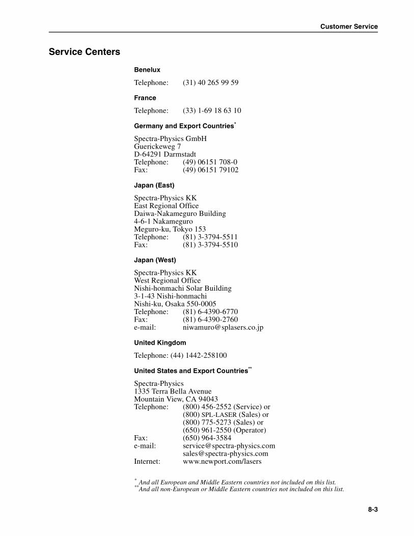
Customer Service
Service Centers
Benelux
Telephone: (31) 40 265 99 59
France
Telephone: (33) 1-69 18 63 10
Germany and Export Countries*
Spectra-Physics GmbHGuerickeweg 7D-64291 DarmstadtTelephone: (49) 06151 708-0Fax: (49) 06151 79102
Japan (East)
Spectra-Physics KKEast Regional OfficeDaiwa-Nakameguro Building4-6-1 NakameguroMeguro-ku, Tokyo 153Telephone: (81) 3-3794-5511Fax: (81) 3-3794-5510
Japan (West)
Spectra-Physics KKWest Regional OfficeNishi-honmachi Solar Building3-1-43 Nishi-honmachiNishi-ku, Osaka 550-0005Telephone: (81) 6-4390-6770Fax: (81) 6-4390-2760e-mail: [email protected]
United Kingdom
Telephone: (44) 1442-258100
United States and Export Countries**
Spectra-Physics1335 Terra Bella AvenueMountain View, CA 94043Telephone: (800) 456-2552 (Service) or
(800) SPL-LASER (Sales) or(800) 775-5273 (Sales) or(650) 961-2550 (Operator)
Fax: (650) 964-3584e-mail: [email protected]
[email protected]: www.newport.com/lasers
* And all European and Middle Eastern countries not included on this list.**And all non-European or Middle Eastern countries not included on this list.
8-3

Millennia Pro s-Series Diode-Pumped, CW Visible Lasers
8-4

Appendix A Status Codes
Listed below are all the status codes and messages that might be displayedwhile using the Millennia® Pro s-Series system. Most codes are self-explanatory and most errors can be corrected by the operator. In the eventthe error cannot be corrected or the action required to correct the error isnot known, call your Spectra-Physics service representative. Before call-ing, write down the code and message, and the version number of the sys-tem software.
Code 0 to 126 are generated by the Model J40 or Model J80 power supply,codes 127 and up are generated by the Millennia Pro s laser head. Codes142 to 147 are latched interlock messages that indicate the power supplyshut off without a command to do so. These latched interlock messages arecleared by either:
a. pressing the LASER POWER switch on the Controller, or
b. sending the OFF command through the RS-232 port.
The Info menu HST line on the Controller lists the three most recent statuscodes with the most recent listed first. The RS-232 ?H query reports themost recent 16 codes, again with the most recent listed first.
Table A-1: Status Codes, Firmware Version 0456-9100 rev B
Code (LCD Line 2) LCD Line 3 LCD Line 4 Action
0 (in History buffer only) (in History buffer only) System OK
1 Laser ON PowerMode OK
2 Laser ON CurrentMode OK
3 Laser ON PowerMode Adjust
4 Laser ON CurrentMode Adjust
5 Laser Diodes OFF Ready Ready to turn on
8 Sleep Mode OK Press power button
10 Low Flow In Chiller Check chiller function and settings
11 Low Level In Chiller Check chiller function and settings
25 Diode Temps. At Setpoint Call Spectra-Physics Service
54 ZModem Trans. Failure Check RS-232 cable
56 Watchdog expired turn laser key Cycle keyswitch on
58 Watchdog working normally
88 Diode Therm Short Call Spectra-Physics Service
89 Diode Therm Open Call Spectra-Physics Service
A-1

Millennia Pro s-Series Diode-Pumped, CW Visible Lasers
90 Diode MaxT Exceed Call Spectra-Physics Service
91 Diode Over Temp. Call Spectra-Physics Service
92 Diode Under Temp. Call Spectra-Physics Service
100 Diode Temperature Call Spectra-Physics Service
101 HSink Over Temp. Call Spectra-Physics Service
102 HSink Under Temp. Call Spectra-Physics Service
103 HSink Therm Short Call Spectra-Physics Service
104 HSink Therm Open Call Spectra-Physics Service
105 HSink MaxT Exceed Call Spectra-Physics Service
116 Interlocks Cleared
117 Fuse Interlock Check fuses and electrical service
118 System Interlock Call Spectra-Physics Service
119 User Interlock Check user installed safety switch or jumper plugs; cycle power off/on
120 Key Switch ILK Cycle AC power and keyswitch off/on
121 Remote Interlock Check jumper plugs;cycle power off/on
122 Head Interlock Make sure laser head cover has not been loosened;call Spectra-Physics Service
123 Boot test Fail Call Spectra-Physics Service
124 Boot Test In Progress
131 Head Overtemp Check Chiller Check chiller and hoses;Call Spectra-Physics Service
141 Head Error, no comm. Check IIC or cables Check cable connections
149 Tower Temp Too high Check chiller and hoses;call Spectra-Physics Service
150 Diode EEPROM IIC Check IIC or cables Check cable connections
151 Main EEPROM IIC Check IIC or cables Check cable connections
152 Error Diode #1 Hours invalid Call Spectra-Physics Service
153 Error Diode #2 Hours invalid Call Spectra-Physics Service
201 Current Calib. Diode 1 Call Spectra-Physics Service
202 Current Calib. Diode 2 Call Spectra-Physics Service
205 Temp. Calib. Diode 1 Call Spectra-Physics Service
206 Temp. Calib. Diode 2 Call Spectra-Physics Service
209 SHG temperature Setting Verify doubling crystal temperature;run SHG Optimization routine
Table A-1: Status Codes, Firmware Version 0456-9100 rev B
Code (LCD Line 2) LCD Line 3 LCD Line 4 Action
A-2
Notes
Notes-1

Millennia Pro s-Series Diode-Pumped, CW Visible Lasers
Notes-2

Notes
Notes-3

Millennia Pro s-Series Diode-Pumped, CW Visible Lasers
Notes-4

Notes
Notes-5

Millennia Pro s-Series Diode-Pumped, CW Visible Lasers
Notes-6

Report Form for Problems and Solutions
We have provided this form to encourage you to tell us about any difficul-ties you have experienced in using your Spectra-Physics instrument or itsmanual—problems that did not require a formal call or letter to our servicedepartment, but that you feel should be remedied. We are always interestedin improving our products and manuals, and we appreciate all suggestions.
Thank you.
From:
Name
Company or Institution
Department
Address
Instrument Model Number Serial Number
Problem:
Suggested Solution(s):
Mail To: FAX to:
Spectra-Physics, Inc. Attention: Quality ManagerQuality Manager (650) 961-71011330 Terra Bella Avenue, M/S 15-50Post Office Box 7013Mountain View, CA 94039-7013U.S.A.
E-mail: [email protected]/lasers
