millenium transponder reader manual
TRANSCRIPT
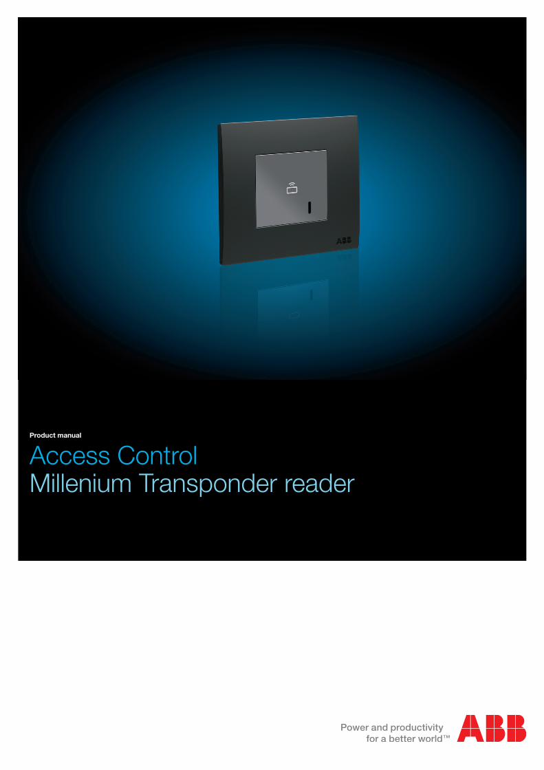
Access ControlMillenium Transponder reader
Product manual
2 Contents | Access control
Access Control Contents
Contents
1 Technical features ............................................................................. 31.1 Transponder reader ........................................................................................ 31.1.1 Technical data ........................................................................................................ 31.1.2 Access Control function ........................................................................................ 41.1.3 Connection diagram .............................................................................................. 51.2 Power supply ................................................................................................. 61.3 Connection and wiring ................................................................................... 61.4 Outdoor installation ........................................................................................ 6
2 Commissioning ................................................................................. 72.1 General ........................................................................................................... 72.2 Function ......................................................................................................... 82.2.1 Actuator ................................................................................................................. 92.2.2 Linked to access control...................................................................................... 102.2.3 Linked to card holder ........................................................................................... 112.2.4 Common parameters ........................................................................................... 12
3 Operation of communication objects ........................................... 13
Access control | Technical features 3
Access Control Technical features
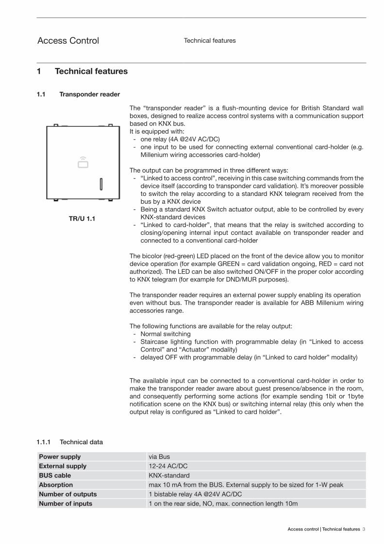
1 Technical features
1.1 Transponder reader
The “transponder reader” is a flush-mounting device for British Standard wall boxes, designed to realize access control systems with a communication support based on KNX bus.It is equipped with:
- one relay (4A @24V AC/DC) - one input to be used for connecting external conventional card-holder (e.g.
Millenium wiring accessories card-holder)
The output can be programmed in three different ways: - “Linked to access control”, receiving in this case switching commands from the
device itself (according to transponder card validation). It’s moreover possible to switch the relay according to a standard KNX telegram received from the bus by a KNX device
- Being a standard KNX Switch actuator output, able to be controlled by every KNX-standard devices
- “Linked to card-holder”, that means that the relay is switched according to closing/opening internal input contact available on transponder reader and connected to a conventional card-holder
The bicolor (red-green) LED placed on the front of the device allow you to monitor device operation (for example GREEN = card validation ongoing, RED = card not authorized). The LED can be also switched ON/OFF in the proper color according to KNX telegram (for example for DND/MUR purposes).
The transponder reader requires an external power supply enabling its operationeven without bus. The transponder reader is available for ABB Millenium wiring accessories range.
The following functions are available for the relay output: - Normal switching - Staircase lighting function with programmable delay (in “Linked to access
Control” and “Actuator” modality) - delayed OFF with programmable delay (in “Linked to card holder” modality)
The available input can be connected to a conventional card-holder in order to make the transponder reader aware about guest presence/absence in the room, and consequently performing some actions (for example sending 1bit or 1byte notification scene on the KNX bus) or switching internal relay (this only when the output relay is configured as “Linked to card holder”.
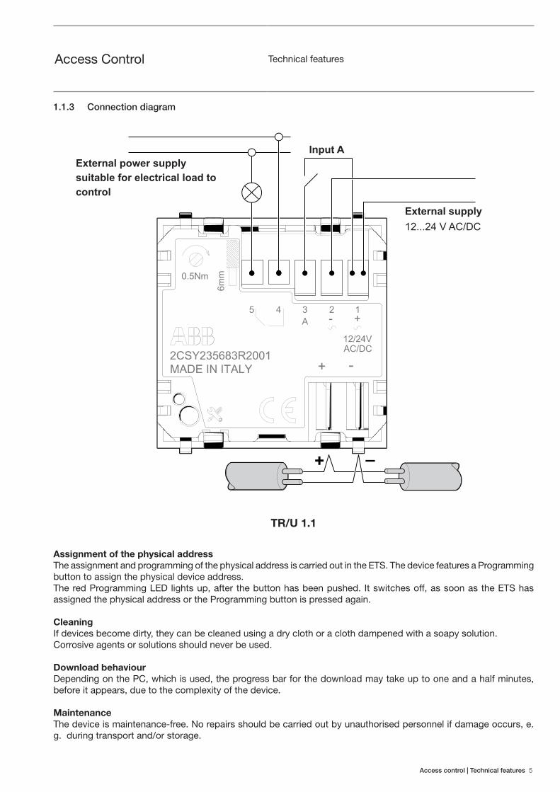
TR/U 1.1
1.1.1 Technical data
Power supply via BusExternal supply 12-24 AC/DCBUS cable KNX-standardAbsorption max 10 mA from the BUS. External supply to be sized for 1-W peakNumber of outputs 1 bistable relay 4A @24V AC/DCNumber of inputs 1 on the rear side, NO, max. connection length 10m
4 Technical features | Access control
Access Control Technical features
Use environment class 3k5 (inside, dry)Operating temperature -5 ... +50 °CRelative humidity max 90% (non condensating)Connection to bus standard bus connectorElectric connections Screw terminal 0.5 NmProtection degree IP20Dimensions 44 x 44 x 43mmWeight approx. 50gReference standards EN50090-2-2, EN 50491, EN 50364, ETSI EN 300 330-2
Device type Application program Maximum number of communication objects
Maximum number of group addresses
Maximum number of associations
TR/U 1.1 Access control transponder reader
16 255 255
1.1.2 Access Control function
TAG validation schemeWhite list - local scheme (communication bus not required), Black list - local scheme (communication bus not required) Central scheme (White or Black list) - Requires Konnex Bus
Event notification upon system supervision
Only possible if the communication bus is available.Available modes:
- Spontaneous Emission - Spontaneous Emission with receipt confirmation request upon supervision
(handshake)
Notifications and validation events characteristics
Information about: Event time stamp (HH,MM,SS), TAG ID, event outcome (access granted or denied)
Buffer memory for eventsThe device can store up to 64 events to deal with the communication bus unavailability due to heavy traffic.
Timeslots
On a weekly basis (Sunday-Saturday)A specific access profile can be associated with each different 256 user groups. Each profile can be a combination of 12 simple timeslots.
Maximum number of TAGs in white-list memory
128
Maximum number plant codes in memory
128
Maximum number time-slot that can be defined
12
Access control | Technical features 5
Access Control Technical features
TR/U 1.1
+ –
12...24 V AC/DC
Input A
Assignment of the physical addressThe assignment and programming of the physical address is carried out in the ETS. The device features a Programming button to assign the physical device address. The red Programming LED lights up, after the button has been pushed. It switches off, as soon as the ETS has assigned the physical address or the Programming button is pressed again.
CleaningIf devices become dirty, they can be cleaned using a dry cloth or a cloth dampened with a soapy solution. Corrosive agents or solutions should never be used.
Download behaviourDepending on the PC, which is used, the progress bar for the download may take up to one and a half minutes, before it appears, due to the complexity of the device.
MaintenanceThe device is maintenance-free. No repairs should be carried out by unauthorised personnel if damage occurs, e. g. during transport and/or storage.
1.1.3 Connection diagram
External power supply suitable for electrical load to control
External supply
6 Technical features | Access control
Access Control Technical features
1.2 Power supply
All devices in the range require an external 12 - 24V AC/DC power supply, allowing them to operate (e.g. opening of electric lock) even in the event of a lack of bus voltage.
For system sizing (number and type of power supplies to use), bear in mind that each access control device draws a peak power of 1W.
ABB recommends using a dedicated power supply/transformer to power the electric lock (not the same one used for the access control devices range), as the power draw of the electric lock is not usually known beforehand and can invalidate the correct sizing of the power supply for the access control devices, causing outages and malfunctions. Where installation requirements should necessitate the use of a common power supply/transformer (for example one in each room for applications such as hotels), it is essential to consider the maximum possible power draw of the electric lock and subtract this from the available power provided by the power supply/transformer: the residual power must be sufficient to power all access control devices running on that power supply/transformer.
For powering the access control devices, ABB recommends the use of stabilised power supplies (for example CP-D from the ABB range) as opposed to transformers. When powering access control devices with alternating current, it is important to remember that transformers for discontinuous loads CANNOT be used to power the access control devices.
An example of an ideal configuration for the sizing of the access control devices’ power supply is given below:
- Dedicated power supply/transformer for electric lock - DC power supply for the access control devices with dedicated stabilised transformer, chosen on the basis of
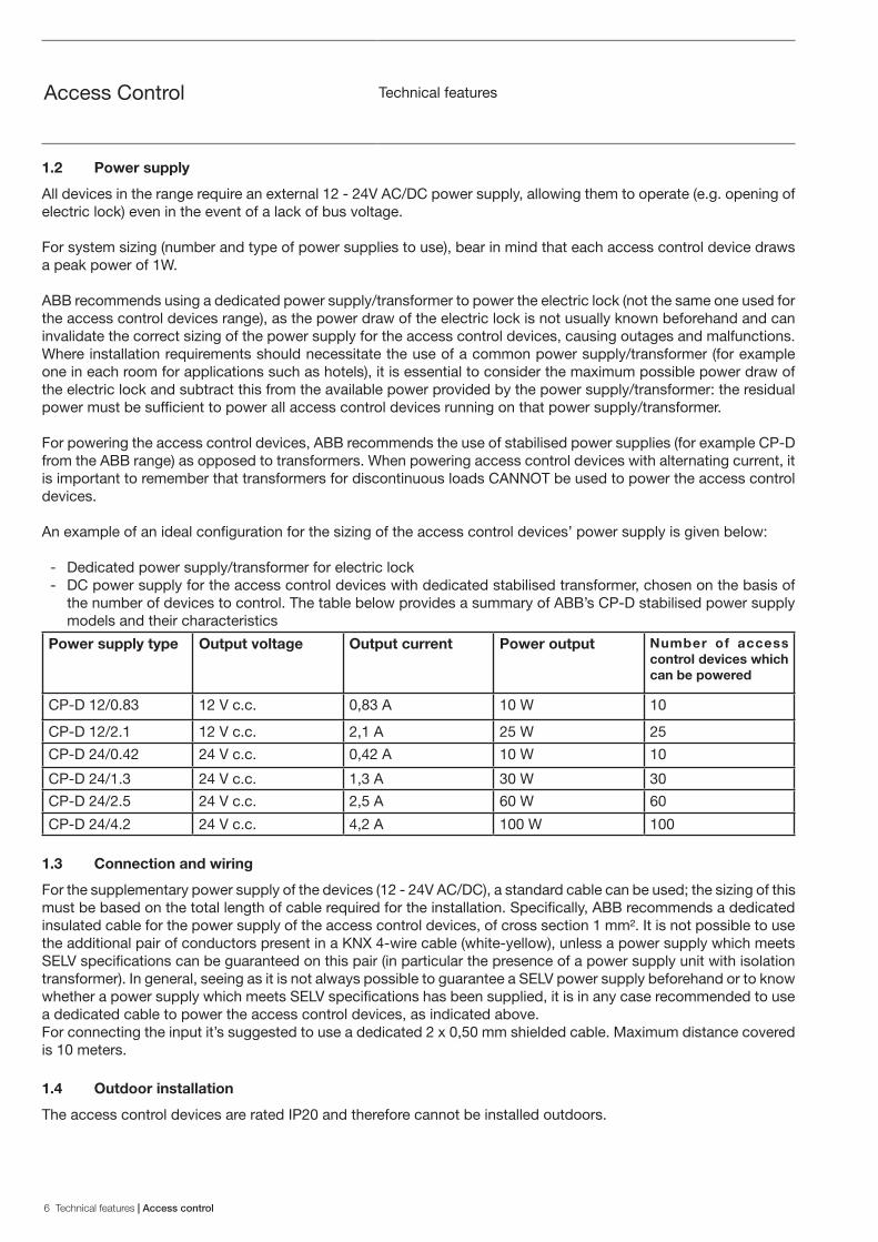
the number of devices to control. The table below provides a summary of ABB’s CP-D stabilised power supply models and their characteristics
Power supply type Output voltage Output current Power output Number of access control devices which can be powered
CP-D 12/0.83 12 V c.c. 0,83 A 10 W 10
CP-D 12/2.1 12 V c.c. 2,1 A 25 W 25
CP-D 24/0.42 24 V c.c. 0,42 A 10 W 10
CP-D 24/1.3 24 V c.c. 1,3 A 30 W 30
CP-D 24/2.5 24 V c.c. 2,5 A 60 W 60
CP-D 24/4.2 24 V c.c. 4,2 A 100 W 100
1.3 Connection and wiring
For the supplementary power supply of the devices (12 - 24V AC/DC), a standard cable can be used; the sizing of this must be based on the total length of cable required for the installation. Specifically, ABB recommends a dedicated insulated cable for the power supply of the access control devices, of cross section 1 mm². It is not possible to use the additional pair of conductors present in a KNX 4-wire cable (white-yellow), unless a power supply which meets SELV specifications can be guaranteed on this pair (in particular the presence of a power supply unit with isolation transformer). In general, seeing as it is not always possible to guarantee a SELV power supply beforehand or to know whether a power supply which meets SELV specifications has been supplied, it is in any case recommended to use a dedicated cable to power the access control devices, as indicated above.For connecting the input it’s suggested to use a dedicated 2 x 0,50 mm shielded cable. Maximum distance covered is 10 meters.
1.4 Outdoor installation
The access control devices are rated IP20 and therefore cannot be installed outdoors.
Access control | Commissioning 7
Access Control Commissioning
2 Commissioning
The main functions of the access control devices are described in this section.Parametrisation is performed via the Engineering Tool ETS Software application program.For the parametrisation you need a pc desktop or a laptop with ETS and connection to the KNX system (obtainable for example by means of RS232, USB or IP Interface).
2.1 General
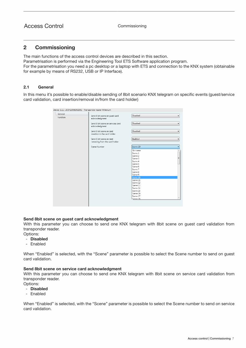
In this menu it’s possible to enable/disable sending of 8bit scenario KNX telegram on specific events (guest/service card validation, card insertion/removal in/from the card holder)
Send 8bit scene on guest card acknowledgment With this parameter you can choose to send one KNX telegram with 8bit scene on guest card validation from transponder reader.Options:
- Disabled - Enabled
When “Enabled” is selected, with the “Scene” parameter is possible to select the Scene number to send on guest card validation.
Send 8bit scene on service card acknowledgment With this parameter you can choose to send one KNX telegram with 8bit scene on service card validation from transponder reader.Options:
- Disabled - Enabled
When “Enabled” is selected, with the “Scene” parameter is possible to select the Scene number to send on service card validation.
8 Commissioning | Access control
Access Control Commissioning
Send 8bit scene on card insertion in the card holder With this parameter you can choose to send one KNX telegram with 8bit scene when a card is inserted into the conventional card-holder connected to transponder reader through its internal input.
Options: - Disabled - Enabled
When “Enabled” is selected, with the “Scene” parameter is possible to select the Scene number to send on card insertion in the card holder.
Send 8bit scene on card removing from the card holder With this parameter you can choose to send one KNX telegram with 8bit scene when a card is removed from the conventional card-holder connected to transponder reader through its internal input.
Options: - Disabled - Enabled
When “Enabled” is selected, with the “Scene” parameter is possible to select the Scene number to send on card removal from the card holder.
2.2 Function
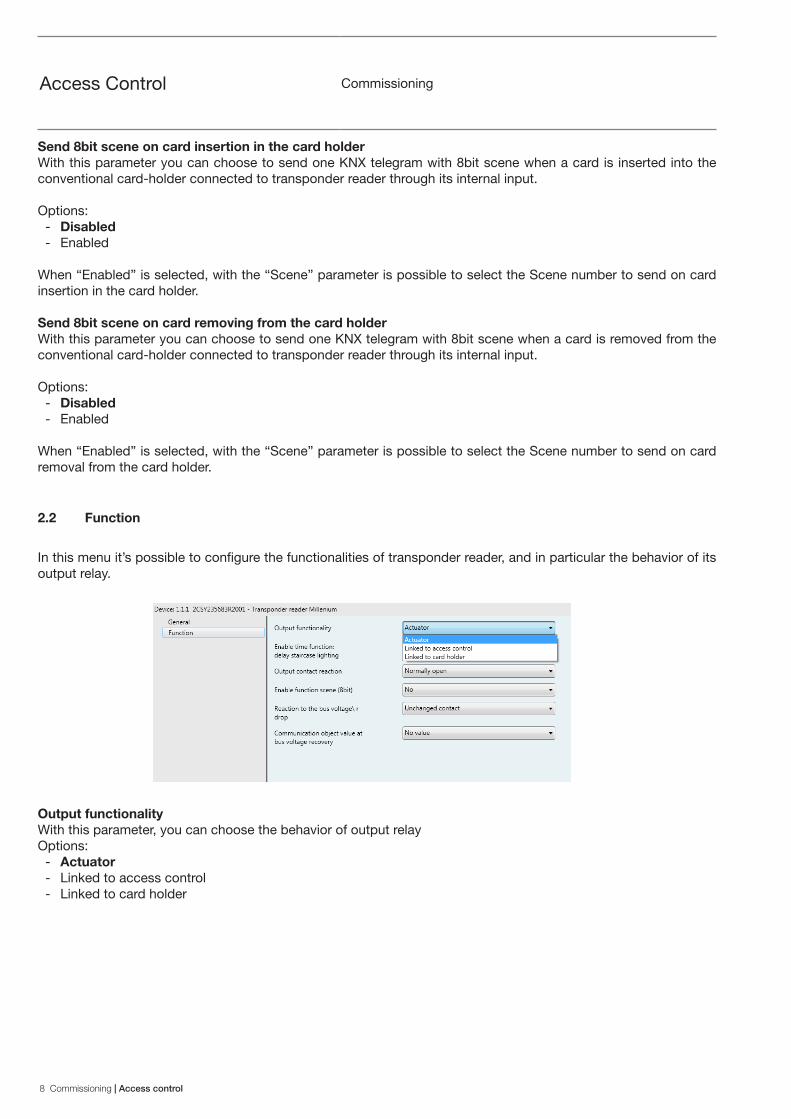
In this menu it’s possible to configure the functionalities of transponder reader, and in particular the behavior of its output relay.
Output functionalityWith this parameter, you can choose the behavior of output relayOptions:
- Actuator - Linked to access control - Linked to card holder
Access control | Commissioning 9
Access Control Commissioning
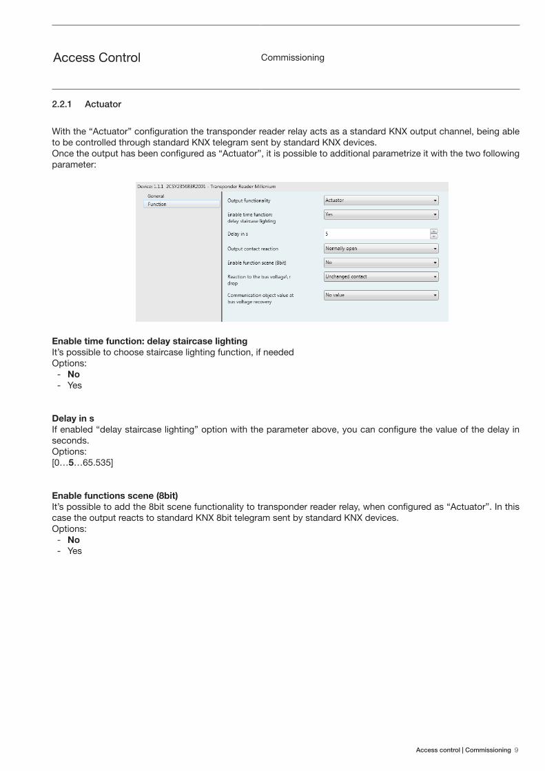
2.2.1 Actuator
With the “Actuator” configuration the transponder reader relay acts as a standard KNX output channel, being able to be controlled through standard KNX telegram sent by standard KNX devices.Once the output has been configured as “Actuator”, it is possible to additional parametrize it with the two following parameter:
Enable time function: delay staircase lightingIt’s possible to choose staircase lighting function, if neededOptions:
- No - Yes
Delay in sIf enabled “delay staircase lighting” option with the parameter above, you can configure the value of the delay in seconds.Options:[0…5…65.535]
Enable functions scene (8bit)It’s possible to add the 8bit scene functionality to transponder reader relay, when configured as “Actuator”. In this case the output reacts to standard KNX 8bit telegram sent by standard KNX devices.Options:
- No - Yes

10 Commissioning | Access control
Access Control Commissioning
2.2.2 Linked to access control
With the “Linked to access control” configuration, the transponder reader relay is switched if it recognizes a valid card. Moreover the output is able to be switched also by means of standard KNX 1bit telegram sent on proper communication object (Switch).Once the output has been configured as “Linked to access control”, it is possible to additional parametrize it with the two following parameter:
Enable time function: electric lock delayIt’s possible to choose electric lock delay function, if neededOptions:
- No - Yes
Dealy in sIf enabled “electric lock delay” option with the parameter above, you can configure the value of the delay in milliseconds.Options:[0…1000…65.535]

Access control | Commissioning 11
Access Control Commissioning
2.2.3 Linked to card holder
With the “Linked to card holder” configuration, the transponder reader relay is switched when a card is inserted into or removed from a conventional card holder (e.g. Millennium card holder) connected to transponder reader with its internal binary input.Once the output has been configured as “Linked to card holder”, it is possible to additional parametrize it with the two following parameter:Enable time function: delay after card removal
It’s possible to choose delay after card removal, if neededOptions:
- No - Yes
Dealy in sIf enabled “delay after card removal” option with the parameter above, you can configure the value of the delay in seconds.Options:[0…60…65.535]
12 Commissioning | Access control
Access Control Commissioning
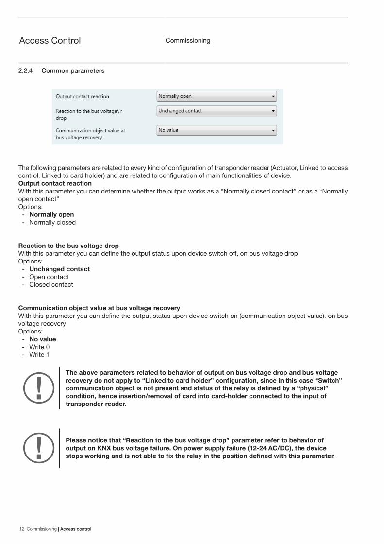
2.2.4 Common parameters
The following parameters are related to every kind of configuration of transponder reader (Actuator, Linked to access control, Linked to card holder) and are related to configuration of main functionalities of device.Output contact reactionWith this parameter you can determine whether the output works as a “Normally closed contact” or as a “Normally open contact”Options:
- Normally open - Normally closed
Reaction to the bus voltage dropWith this parameter you can define the output status upon device switch off, on bus voltage dropOptions:
- Unchanged contact - Open contact - Closed contact
Communication object value at bus voltage recoveryWith this parameter you can define the output status upon device switch on (communication object value), on bus voltage recoveryOptions:
- No value - Write 0 - Write 1
The above parameters related to behavior of output on bus voltage drop and bus voltage recovery do not apply to “Linked to card holder” configuration, since in this case “Switch” communication object is not present and status of the relay is defined by a “physical” condition, hence insertion/removal of card into card-holder connected to the input of transponder reader.
Please notice that “Reaction to the bus voltage drop” parameter refer to behavior of output on KNX bus voltage failure. On power supply failure (12-24 AC/DC), the device stops working and is not able to fix the relay in the position defined with this parameter.
Access control | Operation of communication objects 13
Access Control Operation of communication objects
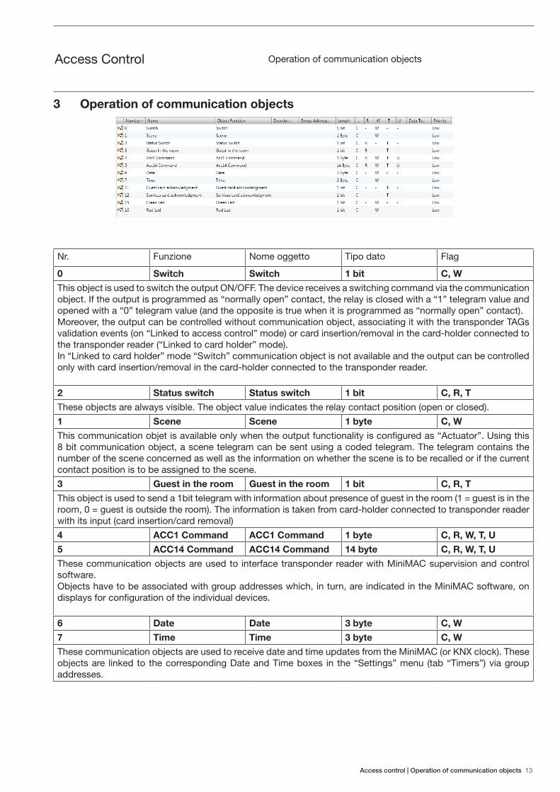
3 Operation of communication objects
Nr. Funzione Nome oggetto Tipo dato Flag
0 Switch Switch 1 bit C, W
This object is used to switch the output ON/OFF. The device receives a switching command via the communication object. If the output is programmed as “normally open” contact, the relay is closed with a “1” telegram value and opened with a “0” telegram value (and the opposite is true when it is programmed as “normally open” contact).Moreover, the output can be controlled without communication object, associating it with the transponder TAGs validation events (on “Linked to access control” mode) or card insertion/removal in the card-holder connected to the transponder reader (“Linked to card holder” mode).In “Linked to card holder” mode “Switch” communication object is not available and the output can be controlled only with card insertion/removal in the card-holder connected to the transponder reader.
2 Status switch Status switch 1 bit C, R, T
These objects are always visible. The object value indicates the relay contact position (open or closed).
1 Scene Scene 1 byte C, W
This communication objet is available only when the output functionality is configured as “Actuator”. Using this 8 bit communication object, a scene telegram can be sent using a coded telegram. The telegram contains the number of the scene concerned as well as the information on whether the scene is to be recalled or if the current contact position is to be assigned to the scene.
3 Guest in the room Guest in the room 1 bit C, R, T
This object is used to send a 1bit telegram with information about presence of guest in the room (1 = guest is in the room, 0 = guest is outside the room). The information is taken from card-holder connected to transponder reader with its input (card insertion/card removal)
4 ACC1 Command ACC1 Command 1 byte C, R, W, T, U
5 ACC14 Command ACC14 Command 14 byte C, R, W, T, U
These communication objects are used to interface transponder reader with MiniMAC supervision and control software.Objects have to be associated with group addresses which, in turn, are indicated in the MiniMAC software, on displays for configuration of the individual devices.
6 Date Date 3 byte C, W
7 Time Time 3 byte C, W
These communication objects are used to receive date and time updates from the MiniMAC (or KNX clock). These objects are linked to the corresponding Date and Time boxes in the “Settings” menu (tab “Timers”) via group addresses.
14 Operation of communication objects | Access control
Access Control Operation of communication objects
9 Guest Card Ack Scene
Guest card acknowledgment scene
1 byte C, T
10 Services Card Ack Scene
Service card acknowledgment scene
1 byte C, T
These objects are available only if previously enabled in the menu “General”. With these objects is possible to send 1byte scene telegram on transponder TAGs validation events (Guest Card/Service Card)
11 Guest card acknowledgment
Guest card acknowledgment
1 bit C, T
12 Service card acknowledgment
Service card acknowledgment
1 bit C, T
These objects are available only if previously enabled in the menu “General”. With these objects is possible to send 1 bit telegram on transponder TAGs validation events (Guest Card/Service Card)
13 Card insertion scene
Card insertion scene
1 byte C, T
14 Card insertion removal
Card insertion removal
1 byte C, T
These objects are available only if previously enabled in the menu “General”. With these objects is possible to send 1byte scene telegram on card insertion/removal into the card-holder connected to transponder reader with its input
15 Green Led Green Led 1 byte C, W
16 Red Led Red Led 1 byte C, W
Through these communication objects you can control the two color LEDs’ status directly over the bus. To switch the LED on, you simply need to send a telegram containing the value 1 to switch it on, or value 0 to switch it off.

Access control| Notes 15
Notes
2CS
N60
0101
D09
01
Contact us
ABB SACEA division of ABB S.p.A.Wiring accessories, Home & Building automationViale dell’Industria, 1820010 Vittuone (MI), Italy
www.abb.com/knxABB Access Control solutionABB offer for Hotels
The data and illustrations are not binding. We reserve the right to modify the contents of this document on the basis of technical development of the products, without prior notice.Copyright 2015 ABB. All rights reserved.