mihir jha - cosimteccosimtec.com/companyprofile.pdf · · 2014-04-29guide modeled as rbe2 element...
TRANSCRIPT

Mihir Jha
Cosimtec Singapore

Mission We at Cosimtec shall strive to achieve sustained value addition to our stake
holders: Customers, Employee, Investors and Society at large by making
our customers successful through latest CAE Technology and related
services.
Our Mantra To make our customer at ease with CAE.
Our Goal To become trusted advisor and consultant to our customers in selection
and implementation of right CAE technology.

OUR SOLUTIONS
FEMAP WITH NX NASTRAN OPTISHAPE
From Quint Japan
TRAINING & CONSULTATION
FEA PROJECT SERVICES
WHAT DO WE DO?

TRAINING & CONSULTATION
FEA APPRECIATION
BASIC TRAINING ON FEA TOOL
ADVANCED TRAINING
DYNAMIC ANALYSIS TRAINING
NON-LINEAR ANALYSIS TRAINING
CONSULTATION & MENTORING
FEA Project Services
Linear Static
Non-Linear
Dynamic
CFD
Analysis Type
Marine & Offshore
Plant & Machinery
Aerospace
Automotive
Industry
WHAT DO WE DO?

Moonpool Consultants Pte Ltd is a company based in Singapore. They provide three kind of Services: 1. Engineering
I. Basic Design II. Construction Preparation
2. Budget & Procurement 3. On-Site Supervision
Major construction projects To date, Moonpool Consultants Pte Ltd has successfully led several projects to completion: Soehanah - New built jack-up Rig 105 - Conversion of a swamp barge Yani - New built swamp Barge Maera - Re-built swamp barge Raissa - New built swamp Barge

• Jack-up Rig Basic Design • For Water Depth 400 ft • Class ABS
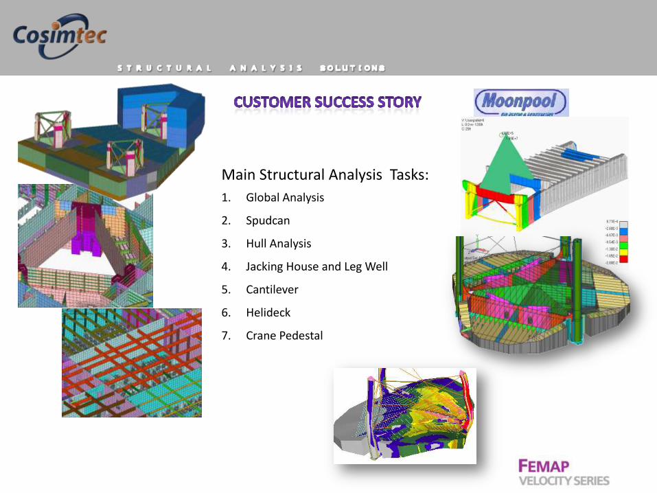
Main Structural Analysis Tasks:
1. Global Analysis
2. Spudcan
3. Hull Analysis
4. Jacking House and Leg Well
5. Cantilever
6. Helideck
7. Crane Pedestal
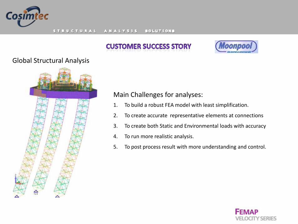
Global Structural Analysis
Main Challenges for analyses:
1. To build a robust FEA model with least simplification.
2. To create accurate representative elements at connections
3. To create both Static and Environmental loads with accuracy
4. To run more realistic analysis.
5. To post process result with more understanding and control.

Typical Software used for such analysis in Industry:
For Global Analysis:
Beam Modeling Software with Hydrodynamic Load
creation capability. They also provide unity check for
the model.
For other detail Analysis:
General purpose software like Femap with NX Nastran.
Limitations of Beam Modeling Software:
1. FEA model is too simplified to fit capabilities of the
software.
2. Easy for Beam modeling very difficult and tedious for
plate modeling and can not create solid model.
3. Sometimes peak results are less reliable.
4. Engineers need to learn two software.
5. Cost of ownership high.

We built a Beam-Plate hybrid model

Pinion modeled as DOF Spring
Guide modeled as RBE2 Element
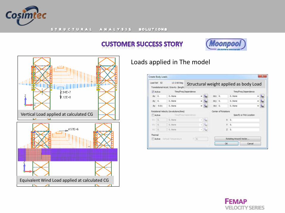
Loads applied in The model
Vertical Load applied at calculated CG
Equivalent Wind Load applied at calculated CG
Structural weight applied as body Load
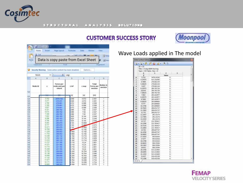
Wave Loads applied in The model Data is copy paste from Excel Sheet

Varying Wave load was created using Data Surface Editor in Femap

Non-Linear analysis eliminated need to determine P-Delta moment through iterative method

NASTRAN RESULTS RESULTANTS INDIVIDUAL STRESSES COMBINED AXIAL AND BENDING
Max UF
Moment
about z
axis, in
plane xy
Moment
about y
axis, in
plane xz
Shear in y Shear in z Axial force Resultant
of moment
Resultant
of shear Stresses Utilisation factors (UF) Compression Tension
3014..Beam
EndA
Plane1
Moment
3015..Beam
EndA
Plane2
Moment
3018..Beam
EndA Pl1
Shear Force
3019..Beam
EndA Pl2
Shear Force
3022..Beam
EndA Axial
Force
Axial Bending Shear Axial Bending Shear
fa/Fa
if
fa/Fa<=.
15
if
fa/Fa>.1
5
UF
At ends
of
member
s fa+fb
UF
fb<Fb? Mz My Vy Vz Faxial M V fa fb max:Fy/
1.25 Filter value
(Mz^2+Mz^
2)^0.5
(Vz^2+Vz^
2)^0.5
-ve is
compres
sion
fa/Fa+fb
/Fb
fa/Fa+C
mfb/((1-
fa/Fe')F
b)
1.25fa/F
y+fb/Fb 552.0 1
[N.m] [N.m] [N] [N] [N] [N.m] [N] [N/mm2] [N/mm2] [N/mm2] - - -
-3.51E+06 1.50E+06 -1.27E+06 4.68E+05 -6.41E+07 3.82E+06 1.35E+06 -327.2 180.3 15.5 0.593 0.327 0.042 0.636 N/A 1.005 1.005 0.919 507.5 0.919 y 1.005
-3.87E+06 2.43E+05 -1.40E+06 8.16E+04 -6.72E+07 3.88E+06 1.40E+06 -343.0 183.1 16.1 0.621 0.332 0.044 0.666 N/A 1.044 1.044 0.953 526.1 0.953 y 1.044
-3.99E+06 -1.71E+05 -1.46E+06 -2.15E+04 -6.83E+07 4.00E+06 1.46E+06 -348.2 188.8 16.7 0.631 0.342 0.046 0.676 N/A 1.067 1.067 0.973 537.0 0.973 y 1.067
-3.45E+06 -1.41E+06 -1.24E+06 -4.00E+05 -6.50E+07 3.73E+06 1.30E+06 -331.6 176.1 14.9 0.601 0.319 0.041 0.644 N/A 1.006 1.006 0.920 507.7 0.920 y 1.006
ID CSys ID Set ID Set Value Set Title
3014..Beam
EndA
Plane1
Moment
3015..Beam
EndA
Plane2
Moment
3018..Beam
EndA Pl1
Shear Force
3019..Beam
EndA Pl2
Shear Force
3022..Beam
EndA Axial
Force
19389 0 2 1 2..Storm 0 375ft -470519 187685.4 -191102 -13851.6 -2.92E+07
19390 0 2 1 2..Storm 0 375ft -376152 194525.6 -197325 -7676.54 -2.92E+07
19391 0 2 1 2..Storm 0 375ft -278732 198315.7 -202701 -1481.42 -2.92E+07
19392 0 2 1 2..Storm 0 375ft -178638 199047.4 -204276 -359.641 -2.92E+07
19393 0 2 1 2..Storm 0 375ft -77786.5 199225.1 -204976 762.6423 -2.92E+07
19394 0 2 1 2..Storm 0 375ft 23431.03 198848.6 -204796 1882.439 -2.92E+07
19395 0 2 1 2..Storm 0 375ft 124539.5 197919.3 -203739 2996.765 -2.92E+07
19396 0 2 1 2..Storm 0 375ft 225146.5 196439.5 -201810 4102.656 -2.92E+07
19397 0 2 1 2..Storm 0 375ft -448124 -189065 -182618 18063.6 -2.79E+07
19398 0 2 1 2..Storm 0 375ft -357947 -197984 -188547 11922.29 -2.79E+07
19399 0 2 1 2..Storm 0 375ft -264862 -203870 -193704 5751.078 -2.79E+07
19400 0 2 1 2..Storm 0 375ft -169211 -206710 -195133 4639.575 -2.79E+07
19401 0 2 1 2..Storm 0 375ft -72874.5 -209000 -195763 3516.748 -2.79E+07
19402 0 2 1 2..Storm 0 375ft 23792.79 -210737 -195591 2385.461 -2.79E+07
19403 0 2 1 2..Storm 0 375ft 120355.9 -211914 -194620 1248.597 -2.79E+07
Spread Sheet with Formulae as specified by ABS for Unity check
Result from Femap with NX Nastran
Benefits:
1. Entire structural analysis performed using Femap with NX Nastran.
2. FEA engineers spent less time in learning the software and
focused more in acquiring expertise on it.
3. Engineers could reuse models for more detailed analysis.
4. Robust FEA modeling of Femap enables relatively faster design
change verification.
5. Cost of ownership of one software is always lower.

Deflection Contour plot
Main Hull Jack-Up Oil Rig
Class Approved by ABS

Static Analysis Pontoon Ship Hull Static Analysis Static Analysis Kiln-Hood
Beams Cross-Section can be visualized

Frequency Response
Function Random Z-Dir
Dynamic Shock 15G-11 ms Z-Dir
Coating
Aluminium
Rubber 1 mm Thick

Static Analysis Inspection Machine
Crane Pulley Thermal Analysis Electronic Device
Non-Linear Analysis Rubber Seal


Electronic Enclosure
Marine Tubeaxial Fan Water Pump
