migrate to ipv6 on 6pe with mpls-te: questions on ... · contains the source and destination ipv4...
TRANSCRIPT

Smart Computing Review, vol. 4, no. 2, April 2014
DOI: 10.6029/smartcr.2014.02.001
91
Smart Computing Review
Migrate to IPv6 on 6PE with MPLS-TE: Questions
on Feasibility and Reluctance in Deployment?
Muhammad Farrukh Anwaar and Sameer Qazi
1,2 Electronic and Power Engineering Department, PNEC, National University of Sciences and Technology (NUST) / H-12, Islamabad, Pakistan / [email protected], [email protected]
*Corresponding Author: Muhammad Farrukh Anwaar
Received January 22, 2013; Revised March 08, 2014; Accepted March 13, 2014; Published April 30, 2014
Abstract: Due to the exhaustion of IPv4 addresses, the transition to IPv6 has already begun using
various transition mechanisms. In this paper comparison between two transition mechanism 6PE
and 6to4 tunneling over MPLS (Multiprotocol Label Switching) based network has been
performed. The experimental platform used is based on GNS3/Dynagen using emulated routers on
which multiple TCP and UDP flows were generated between separated IPv6 network traversing
through IPv4 based core. Traffic were generated using both transition mechanism and are compared
to native IPv4 based MPLS network. Performance metric used are end-to-end delay, jitter and
throughput, these parameters are also analyzed statistically using ANOVA, F-Test and T-Test to
support a conclusion. Further, MPLS Traffic-Engineering (TE) using RSVP-TE signalling is
applied, describing the implementation and performance test and analysis of TE tunnels on 6PE for
IPv6 traffic. The same test-bed is used to implement and observe MPLS-TE behavior and
throughput of 6PE based MPLS-TE to that of native IPv4 based MPLS-TE. Concluding, throughput
of 6PE and 6to4 is around 99% and 96%, respectively, as compared to that of native IPv4.
Keywords: MPLS, traffic-engineering, 6PE, 6to4, IPv6 transition, tunneling, performance analysis
Introduction
Pv6, Internet Protocol version 6 is the next version of the network layer protocol being used for communication
between all types of network devices on the internet. IPv6 has been in existence for many years, but recently the
deployment of IPv6 has accelerated greatly. But, IPv6 is still under continuous development and is maturing as real-
I
T
C
C

Anwaar et al.: Migrate to IPv6 on 6PE with MPLS-TE: Questions on Feasibility and Reluctance in
92
world deployments expose gaps in either the protocol or the deployment methodology of the protocol.
IPv6 solves exhaustion problem of IPv4 by providing 128 bit addresses, approximately 3.4×1038
addresses. As
compared to IPv4 32-bit addresses, approximately 4.3 billion addresses [1] which would be good to assign approximately
6.67×1027
IPv6 addresses per square meter on our planet. Existing IPv4 NAT (Network Address Translation) using local
private addresses (RFC 1918) could be used, but NAT introduces overhead and network application problems.
In the long run there is need of IPv6, but this change cannot occur in a day. IPv4 to IPv6 transition mechanisms have
been introduced for IPv4 and IPv6 coexistence, interoperability and smooth transition. These mechanisms could be divided
into [1]:
Dual stack: Both IPv4 and IPv6 stacks are operating at the same time in the network nodes,
Tunnelling: For communication between disjoint IPv4 network IPv6 packets are encapsulated in IPv4 tunnels - 6to4
tunnel, 6PE (IPv6 over IPv4 MPLS, RFC4798).
Translation: IPv6 packets header are converted into IPv4 packets, vice versa. In this paper performance of IPv6 6to4
tunnel and 6PE has been compared in accordance with native IPv4 on IPv4 Multiprotocol Label Switching (MPLS)
network.
MPLS (Multi-Protocol Label Switching) is approved to accelerate network traffic flow by setting up a specific label
switched path (LSP), this path is identified by a label applied to each packet, thus saving the time involving routing table
lookup to find the interface or the next node to forward the packet [2]. MPLS allows most packets to be forwarded at
switching level (OSI Layer 2) rather than at the routing level (OSI Layer 3). In this paper IPv6 is implemented on IPv4
MPLS infrastructure i.e. 6PE to take advantage of MPLS label switching.
MPLS networks can employ Traffic-Engineering (TE) i.e. MPLS-TE to minimize network congestion by eliminating
the effect of congestion insensitive flows like UDP with congestion sensitive flows like TCP, and optimize network
performance by using under-utilized link by diverting traffic from congested path to un-congested path rather than
following the best-path chosen by an Interior Gateway Protocol (IGP) [3]. This efficiently reduces the occurrence of
congestion and improves service quality in terms of the throughput, delay, jitter, and loss that packets experience.
MPLS-TE brings explicit routing capabilities to MPLS networks. MPLS TE uses extensions to RSVP (Resource
Reservation Protocol), Traffic Engineering RSVP or TE-RSVP (RFC 3209) [4] for establishing LSP path from source to
destination node. MPLS TE also extends the MPLS routing capabilities with support for constraint-based routing. IGPs
usually compute the best path using one or two metrics. Whereas, constraint-based routing can take into account more
detailed information about network like available bandwidth, latency, affinity and other policies. MPLS TE use extension
of link-state protocols (IS-IS and OSPF) to distribute topology information, OSFPv3 for IPv6 prefix distribution.
Currently, most of the ISP are undergoing up-gradation to IPv6 to support the next scheme of addressing, but they want
to deploy IPv6 without any hindrance or outage over current already deployed production IPv4 core network. Core routers
are already overwhelmed with other process intensive routing task, so it would not be a better idea to enable dual stack on
core routers unless a major hardware upgrade is done. So to compare two popular migration schemes, and to analyze the
performance of packet throughput, delay and jitter vary for different real-time, congestion-sensitive and congestion-
insensitive types of traffic when 6PE MPLS-TE is applied.
Two objectives would be covered in the experiments and tests performed in this paper. First objective would be the
analysis of two transition mechanism 6to4 and 6PE as compared to native IPv4, on the MPLS based IPv4 core. The next
objective is to analyze the behavior of 6PE on application of MPLS Traffic-Engineering as compared to MPLS-TE on
native IPv4. Performance parameters like: throughput, delay (RTT), jitter etc. would be compared
The paper is organized as follows. In Section 2 a brief description of related work is presented. Section 3 gives brief
technical background. In Section 4 Experiment platform has been described. In Section 5 and 6 simulations methodology
and traffic parameters are described and are then analyzed. Finally, Section 7 summarizes the conclusion.
Related Works
Lately IPv6 Transition has been in progress and different transition mechanism is being implemented by industry so this
has engaged the interest of many researchers in this domain. Organizations which are transitioning are already aware of its
benefit and limitation of previous IPv4 version [5]. Much research has already been done on transition mechanism and
porting of existing IPv4 networks and application to IPv6, which allows disparate IPv6 networks to communicate with each
other over IPv4 network [6] and throughput, delay, loss and other performance parameters of those different transition
mechanism are compared [7, 8] including comparison and application of QoS on IPv6 based networks and services on it [5,
9]. MPLs IPv6 Tunnelling implemented on Linux, but directly between adjacent PE routers without MPLS P Router
implementation [2] and similar tests were implemented on other software based platform [1, 10]..

Smart Computing Review, vol. 4, no. 2, April 2014
93
Background
■ MPLS for IPv6:
LDP is required to distribute label information to peer routers. Similarly for IPv6 LPD is required to share label information
to peer against IPv6 prefixes. But, IETF’s LDP protocol specification (RFC5036) was composed considering IPv4 in mind,
but not that much considering IPv6. Till this date LDP support for IPv6 prefixes is still in the draft because of some
deficiencies regarding to IPv6 usage like: LSP Mapping; LDP Identifier; LDP Discovery; LDP Session establishment and
others. Further details are stated in the IETF draft.
■ Transition Mechanisms
6to4 tunnel: It is a transition mechanism as specified in RFC 3056, IPv6 packets are encapsulated in IPv4 for transport
across an IPv4 network; [1] it is an automatic tunnelling mechanism, which is typically implemented on edge routers. The
tunnel destination is the embedded IPv4 address from the IPv6 destination address in the IPv6 header. The IANA has
assigned prefix 2002::/16 for 6to4 tunnelling scheme. The IPv6 addresses, starting with the 2002::/16 prefix, are known as
6to4 addresses. To construct the 48-bit 6to4 prefix, 2002 is prepended to the hex value of 32-bit IPv4 address representing a
host or a network behind it. For example, using an IP address of 192.168.1.2 makes the corresponding 6to4 prefix
2002:C0A8:0102::/48.
The 6to4 tunnelling while encapsulating the IPv6 packet in an IPv4 packet uses protocol number 41. The IPv4 header
contains the Source and Destination IPv4 addresses. The IPv4 packet body contains the IPv6 header and payload.
IPv6 Data IPv6 header IPv4 header IPv4 MPLS label L2 header
40 bytes 20 bytes 4 bytes
Figure 1. IPv6 Packet with 6to4 tunnel encapsulation
6PE: This allows the use of existing IPv4 MPLS infrastructure to transport IPv6. The provider edge (PE) routers have the
IPv6 routing capability, but the provider (P) routers do not have IPv6 routing functionality enabled. The service providers
can provide IPv6 services (connectivity between the isolated IPv6 domains) without upgrading their core networks to IPv6.
IPv6 packets are received on 6PE edge routers, encapsulated by the ingress 6PE router in which an MPLS label
representing destination IPv6 address is added and a topmost transport IPv4 MPLS label representing egress 6PE router is
added, this MPLS label is decapsulated by the egress 6PE router and IPv6 information is extracted and routed normally
from there to the destination in IPv6 domain.
To exchange MPLS label information between MPLS 6PE routers, MPLS 6PE routers use multiprotocol Border
Gateway Protocol (MP-BGP) over IPv4 to exchange IPv6 routes and label assigned to them. BGP next-hop conveys about
the reachability of IPv6 addresses by the 6PE router so there is no need of explicit tunnels, dynamically established IPv4
LSP could be used for connectivity between 6PEs. There is also no need for an IPv6 IGP on transit or 6PE routers because
the next hop for an IPv6 route is an IPv4-mapped IPv6 address. This address actually points to the IPv4 address of the
egress 6PE router and therefore only needs an IPv4 IGP to be reachable.
IPv6 Data IPv6 header IPv6 MPLS label IPv4 MPLS label L2 header
40 bytes 4 bytes 4 bytes
Figure 2. IPv6 Packet with 6PE Encapsulation
■ MPLS-TE over 6PE
In [1, 5, 7] the author compared the performance of native IPv6 to IPv4 and found some performance differences between
native IPv4 and IPv6. In comparisons made between native IPv4 and IPv6, IPv6 showed poor performance as compared to
IPv4. Similarly to investigate the impact of TE on IPv6, particularly 6PE, it has been implemented on the test bed for
measuring and analyzing its performance.
In 6PE Traffic Engineering is applied on the top most label, in 6PE encapsulation there are two labels inside one is for
identifying IPv6 interface or path on the destination 6PE node, and top most label is to identify IPv4 LSP and route the
packet to destination 6PE node.

Anwaar et al.: Migrate to IPv6 on 6PE with MPLS-TE: Questions on Feasibility and Reluctance in
94
On the application of Traffic Engineering, path of the top most label would be decided as per RSVP signalling. There
would be a separate tunnel for each path, and as Traffic-Engineered Tunnels are uni-directional, so there would be a
separate tunnel for forward and reverse direction path. For example, if tunnel for forward path is created and not for reverse
path, then the forward path would follow (optimized) TE path but reverse path would follow the normal IGP path.
As in 6PE IPv6 prefixes and the MPLS labels are distributed over MP-BGP to the far end 6PE router and in 6PE
packets follows the path to the BGP next hop router to reach egress 6PE destination. So there is a need of separate BGP
peering between 6PE routers for each tunnel, so the number of BGP peering would equal to the number of separate path
tunnels for 6PE. And then BGP is restricted to advertise only those IPv6 prefixes which would be required to follow the TE
tunnel represented by this BGP next hop, to restrict IPv6 prefix advertisement to peer prefix-list filter is applied. And to
make the relevant BGP next hop to follow the desired TE Tunnel, there is need to statically route the BGP IPv4 next-hop to
the respective TE tunnels, so that BGP next hop would be reachable by that respective TE tunnel. Subsequently, IPv6
follows the path according to the encapsulated next-hop IPv4 MPLS label, so these 6PE traffic would also follow the
respective TE tunnels assigned to them. In MPLS-TE which is applied in the experiments, TE Tunnel paths are defined by
“Explicit” hop-by-hop definition of path on the head end router by specifying the loopback IP address of all the
intermediate hops till tunnel destination.
For example: There is a need to follow two TE tunnels on different paths (bi-directional) Path1 and Path2. So for this it
is required to establish two separate BGP neighbourship over separate IPv4 addresses, these IPv4 addresses could be
assigned on Loopback interfaces. Once BGP neigbourship are established, then configure two separate TE tunnels, when
TE tunnels are UP then static route the next-hop IP of the first BGP neighbor behind the Tunnel 1, and static route the next-
hop IP of the second BGP neighbor behind the Tunnel 2. By doing this BGP next-hop would be reachable by respective
Tunnels only.
Next IPv6 prefixes and their labels have to be shared, so for this there is a need to apply prefix-list filter on each BGP
neighbor to restrict IPv6 prefixes being advertised. So BGP peering 1 would advertise only those prefixes which are
required to follow Path1 to reach destination, similarly, BGP peering 2 would advertise only those prefixes which are
required to follow Path2 to reach destination.
Now IPv6/6PE would be following the TE tunnelled path and if required other TE optimization and parameters could be
applied on TE tunnels.
The Experiment Platform
GNS3 [11, 12] is used as a network emulator which uses Dynagen as hypervisor. GNS3 emulates Cisco routers with Cisco
IOS operating system. All routers, used as P, PE or CE in our topology is same having Cisco IOS version 12.2(33) on
Cisco 7206 VXR.
Figure 3. Base Topology
Base topology as shown in above Figure would be used for all the scenarios mentioned in the following sections,
changes made specific to the scenario would be described in the particular section. Router 1 to 5 are MPLS P Router,
Router 6, 7 are PE router and other routers 8, 9 are CE routers. Normal IPv4 OSPF has been configured as IGP on all the P,
PE and CE for the routing and prefixes reachability. Bandwidth policies as mentioned in the topology diagram is
implemented on all interfaces. Low bandwidth in Kbps for connectivity between core routers (P/PE) is used so that the
effect due to IPv4/IPv6 headers on throughput, delay, jitter and other parameters could be more visible and reflect on
graphs. OSPFv3 has been enabled between CE and PE for communication of IPv6 prefixes between PE and CE. OSPF
would select path PE6-P1-P2-PE7 as best-path between source hosts and destination hosts because of least number of hops
and more bandwidth on this path. So without any Traffic-Engineering applied all flows would compete to utilize the

Smart Computing Review, vol. 4, no. 2, April 2014
95
bandwidth available on the best-path. MPLS has been enabled between all P and PE routers. MPLS labels would be
distributed dynamically between LDP peers. MPLS is not enabled between CE and PE.
■ Traffic Generation
Each host in the topology has CentOS as their OS with IPv6 support. A tool called Iperf [2, 5] is installed on those CentOS
for generating traffic and as a sink for receiving packets. So three hosts on the left (1,2 and 3) would be acting as iperf
clients and other three hosts on the right (4,5 and 6) are acting as iperf server. The client and Server would be used as
follows: Host 1,2 and 3 is client for Server on Host 4,5 and 6 respectively. Iperf would be used in TCP or UDP mode as per
scenario. CentOS and iPerf TCP mode is changed to use Reno. Besides generating traffic, Iperf also assess the network
performance. Iperf gives output of throughput, delay, jitter and packet loss which are to be analyzed. Iperf gives average of
these parameters over the interval, output is received after 5 second interval and each simulation would run for 5 minutes
i.e. 300 seconds. So there are 60 samples to analyze. UDP would also follow the same implementation.
To get more specific impact of delay and jitter, ping traffic is also generated at the same instant during which iperf is
running from client to server. The ping would follow the same path of the TCP/UDP to the destination and back for RTT.
So for determining RTT of the network, RTT of the ping packets would be calculated by the time taken for the packet to go
from client to server and back again, the interval between each successive ping would be 20 milliseconds. Jitter is
calculated from Delay as per RFC 3550 [5].
Comparison of Transition Mechanisms without MPLS-TE
In this section performance comparison between 6PE and 6to4 with that of IPv4 is analyzed.
■ Native IPv4
In this the same network would be used as described in base topology Fig.3 and same default best OSPF path would be
used. Host 1, 2 and 3 would establish a TCP session with Host 4, 5 and 6 respectively, so in total there would be three TCP
sources and sinks. Throughput and other parameters for the traffic between three TCP sources and destinations are recorded.
The throughput output graph would be as follows:
Figure 4. Native IPv4 Throughput
Delay and Jitter output graph would be as follows:
All the TCP flows in scenario 1 followed the same path so would have a similar output graph for delay and jitter which
are indistinguishable to interpret visually.

Anwaar et al.: Migrate to IPv6 on 6PE with MPLS-TE: Questions on Feasibility and Reluctance in
96
Figure 5. Native IPv4 Flow 1
■ IPv6 over 6to4 Tunnel
In this section the performance of IPv6 over 6to4 tunnel would be checked. The same topology is used, but 6to4 tunnel is
enabled between router 6 and 7 and route relevant IPv6 traffic to this tunnel for the IPv6 communication between hosts on
the CEs. Then, like in previous scenario three TCP traffic sessions would be generated between hosts 1, 2, 3 and 4, 5, 6
respectively. But this time these traffic would be communicating over IPv6 addresses using 6to4 tunnel.
The throughput output graph would be as follows:
Figure 6. IPv6 over 6to4 Tunnel Throughput
Delay and Jitter output graph would be as follows:
Figure 7. IPv6 over 6to4 Tunnel Flow 1

Smart Computing Review, vol. 4, no. 2, April 2014
97
All the TCP flows in this scenario would have a similar output graph for delay and jitter.
■ IPv6 over 6PE
In this the section performance of IPv6 over 6PE is checked. The same topology is used, but 6PE would be enabled, for
which MP-BGP would be enabled between router 6 and 7, so that PE would be promoted to 6PE, 6PE would receive far-
end IPv6 addresses and their MPLS Label over this MP-BGP session for the IPv6 communication between hosts on the
CEs. Then, like in previous scenario three TCP traffic sessions would be generated between hosts 1, 2, 3 and 4, 5, 6
respectively.
But this time these traffic would be communicating over IPv6 addresses using dynamic routing of 6PE through OSPF
and MP-BGP.
The throughput output graph would be as follows:
Figure 8. IPv6 over 6PE Throughput
Delay and Jitter output graph would be as follows:
Figure 9. IPv6 over 6PE Tunnel Flow 1
All the TCP flows in this scenario would have a similar output graph for delay and jitter.
■ Analysis
In this section collected data are evaluated, the data collected is very large and the values are close to interpret and to
conclude visually so statistical analysis is also performed.
Throughput:
In the combine graph of the TCP throughput of the previous scenarios it could be clearly seen that the throughput of 6PE is
closer to the throughput of native IPv4 than the throughput of 6to4 tunnel.

Anwaar et al.: Migrate to IPv6 on 6PE with MPLS-TE: Questions on Feasibility and Reluctance in
98
Figure 10. Combine throughput graph of all TCP scenarios
But to evaluate the results of throughput statistically ANOVA (Analysis of Variance) is used [8].
The Null Hypothesis is the mean of throughput of all scenarios are equal, and the Alternative Hypothesis would be at-
least one throughput mean is different.
2
2
( )
1
( 1)
n x x
pF
n
N p
Where,
p = Total number of populations
N = Total number of observations
n = Total number of samples in a population
Table 1. Statistical summary of TCP flows throughput
Groups Count Sum Min Max Average Variance
IPv4 60 7509.4 114.3 128.1 125.1567 10.72623
6PE 60 7462.8 110.1 127.8 124.38 14.91349
6to4 60 7205.8 109.3 128.2 120.0967 24.8627
In this case F is 26.46631and F crit is 3.04701. When F > F crit ANOVA null hypothesis gets rejected, so it could be
declared that the means of the throughput are unequal.
Further, we can see from the Table 1 that the transmission rate of IPv4 is more than any of the others. IPv4 is about 0.8%
more than that of 6PE, whereas about 3% more than that of 6to4 tunneling. This major difference is mainly due to the size
of the packet which data link layer carries. Header across IPv4 payload is around 20+18+4=42 bytes, where 20 bytes is of
IPv4 header, 18 bytes of Ethernet frame and 4 bytes of MPLS label. Whereas in 6PE there are 40+18+4+4=66 bytes, where
40 bytes are of IPv6 header and 4 bytes of IPv4 and IPv6 MPLS labels. Similarly 6to4 tunneling packet header is about 82
(20+40+18+4) bytes. The standard IPv6 header is about 20 bytes larger than that of IPv4, which produces up to 7%
overhead when MPLS LDP is not applied [5] But with MPLS forwarding of IPv6 packets is accelerated and IPv6 route
lookup is performed only on 6PE routers so it is optimized to about 1%.
Delay:
Next ANOVA is performed on delay between all TCP sessions on IPv6, 6PE and 6to4 based communication. Null
Hypothesis would be that mean of all the TCP sessions delay would be same. Similarly, alternative hypothesis would be
that at least mean of one delay is unequal.

Smart Computing Review, vol. 4, no. 2, April 2014
99
Table 2. Statistical summary of all flows delay
Groups Sum Min Max Average Variance
IPv4
TCP flow 1 2079256 92.3 184.4 138.617 708.6846
TCP flow 2 2075358 92.3 184.2 138.3572 708.0267
TCP flow 3 2075457 92.4 184.5 138.3638 717.4278
6PE
TCP flow 1 2575517 125.6 217.5 171.7012 707.9442
TCP flow 2 2570165 125.4 217.3 171.3443 714.1089
TCP flow 3 2562669 125.5 217.2 170.8446 705.6475
6to4
TCP flow 1 3028016 124.7 277.7 201.8677 1982.527
TCP flow 2 3018456 125 278.1 201.2304 1970.98
TCP flow 3 3013874 124.7 277.9 200.9249 1971.466
In ANOVA testing F (9837.418) is greater than F crit (1.938482) so we reject the null hypothesis, and could declare
that the mean delay of all TCP sessions is unequal.
In delay there are about 15000 points so to further analyze this large number of points F-Test has been applied to
evaluate whether variances across each TCP session in the scenarios are equal [8]. Null Hypothesis would be: variance of
delay i = variance of delay j.
2
1
2
2
F
Figure 11. F-Test Result of All Flows Delay
Here F Critical is 1.027226 on which this could be observed that F is not greater than F Critical for 6PE when
compared to IPv4 this means that Null hypothesis is justified for it and variance of delay in 6PE and IPv4 is close. Whereas,
for 6to4 variances difference is clearly observed by F > F Critical.
Next using the variance information about F-Test we would apply T-test. There are different approaches for T-Test
depending on whether variance are same or different. Null Hypothesis would be: delay mean i = delay mean j.
T-Test Equation for same variance:
1 2
2 2
1 1 2 2
1 2 1 2
( ) ( ) 1 1
2
tx x
x x x x
n n n n
Where,
n = Number of subjects in sample
T-Test Equation for different variance:
Anwaar et al.: Migrate to IPv6 on 6PE with MPLS-TE: Questions on Feasibility and Reluctance in
100
1 2
2 2
1 2
1 2
tx x
n n
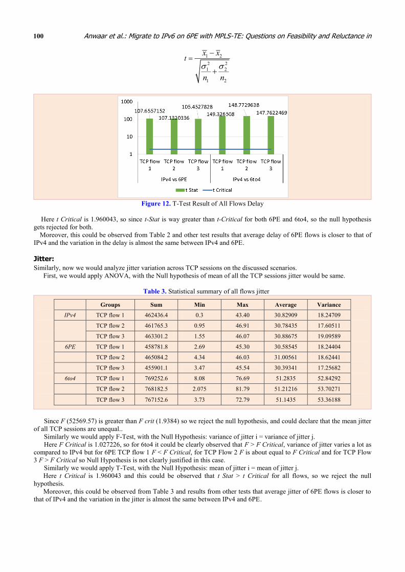
Figure 12. T-Test Result of All Flows Delay
Here t Critical is 1.960043, so since t-Stat is way greater than t-Critical for both 6PE and 6to4, so the null hypothesis
gets rejected for both.
Moreover, this could be observed from Table 2 and other test results that average delay of 6PE flows is closer to that of
IPv4 and the variation in the delay is almost the same between IPv4 and 6PE.
Jitter:
Similarly, now we would analyze jitter variation across TCP sessions on the discussed scenarios.
First, we would apply ANOVA, with the Null hypothesis of mean of all the TCP sessions jitter would be same.
Table 3. Statistical summary of all flows jitter
Groups Sum Min Max Average Variance
IPv4 TCP flow 1 462436.4 0.3 43.40 30.82909 18.24709
TCP flow 2 461765.3 0.95 46.91 30.78435 17.60511
TCP flow 3 463301.2 1.55 46.07 30.88675 19.09589
6PE TCP flow 1 458781.8 2.69 45.30 30.58545 18.24404
TCP flow 2 465084.2 4.34 46.03 31.00561 18.62441
TCP flow 3 455901.1 3.47 45.54 30.39341 17.25682
6to4 TCP flow 1 769252.6 8.08 76.69 51.2835 52.84292
TCP flow 2 768182.5 2.075 81.79 51.21216 53.70271
TCP flow 3 767152.6 3.73 72.79 51.1435 53.36188
Since F (52569.57) is greater than F crit (1.9384) so we reject the null hypothesis, and could declare that the mean jitter
of all TCP sessions are unequal..
Similarly we would apply F-Test, with the Null Hypothesis: variance of jitter i = variance of jitter j.
Here F Critical is 1.027226, so for 6to4 it could be clearly observed that F > F Critical, variance of jitter varies a lot as
compared to IPv4 but for 6PE TCP flow 1 F < F Critical, for TCP Flow 2 F is about equal to F Critical and for TCP Flow
3 F > F Critical so Null Hypothesis is not clearly justified in this case.
Similarly we would apply T-Test, with the Null Hypothesis: mean of jitter i = mean of jitter j.
Here t Critical is 1.960043 and this could be observed that t Stat > t Critical for all flows, so we reject the null
hypothesis.
Moreover, this could be observed from Table 3 and results from other tests that average jitter of 6PE flows is closer to
that of IPv4 and the variation in the jitter is almost the same between IPv4 and 6PE.

Smart Computing Review, vol. 4, no. 2, April 2014
101
Figure 13. F-Test Result of All Flows Jitter
Figure 14. T-Test Result of All Flows Jitter
Processing and queuing overhead:
In IPv6 processing overhead is also increased because for forwarding IPv6 packets more bits have to be looked up. IPv6
forwarding address is 128 bit long which is much longer as compared to IPv4 32 bits address. To perform IP lookup Trie-
Based scheme is mostly used and Sklowers original Trie-Based implementation have been improved to have the worst case
of O(W), where W is the length of address [13] so considering worst-case 4 times more processing overhead is introduced
for a single IPv6 destination. In 6PE this lookup somewhat gets improved due to MPLS label imposition. Core MPLS
routers are just required to lookup for labels to forward packet to an adjacent router, there is no need to traverse complete
IPv6 routing table. IPv6 route lookup is performed only on edge 6PE routers.
IPv6 header is more than that of IPv6, so in a single packet 20+4 (20 more bytes in IPv6 and MPLS label) = 24 bytes
more overhead is introduced, so during automatic MTU discovery of IPv6 lower MTU is discovered for upper layer
protocols. This would recursively give lower payload for TCP, resulting in lower throughput. Lower the actual throughput
is, the more delay and jitter is introduced because due to smaller Maximum Segment Size (MSS) more packets would be
required for the same application layer payload, due to this network abnormality would affect more packets for the same
payload thus varying inter-arrival time. Increased header also occupies queue space and affects the length of a queue in the
buffer. IPv6 header processing is performed only on edge 6PE routers on which, if QoS like WFQ, or Class-based WFQ is
applied that would also significantly improve or prioritize the traffic by reducing packet loss of UDP by up to 4%, but there
was no significant impact by WRED because in WRED when packets are dropped TCP reduces its transmission rate by
reducing windows size whereas UDP continues to face drops [5].
■ Findings and Discussions
In the above graphs and analysis, it could be observed that the throughput of native IPv4 is more than that of 6PE and 6to4
tunnelling on MPLS network, and on closely observing the combined throughput comparison graph of TCPs it could be
further observed that 6PE throughput is closer to that of IPv4 throughput, this is also supported statistically that the average
throughput on IPv4 is around 125.1Kbps and of 6PE is around 124Kbps with that of around 120Kbps of 6to4. Similarly,
when 6PE and 6to4 were compared with UDP traffic, 6PE throughput again outperformed 6to4, 6PE gave average

Anwaar et al.: Migrate to IPv6 on 6PE with MPLS-TE: Questions on Feasibility and Reluctance in
102
throughput of 74.1Kbps as compared to 51.56Kbps of 6to4. So throughput of 6PE and 6to4 is around 99% and 96%,
respectively.
Regarding delay performance it is not as evident from graphs, but from statistical analysis, it can be seen that the
average delay of IPv4 is around 138ms as compared to 6PE 171ms and 6to4 200ms. But the variance of delay is important
for delay sensitive applications like voice etc. so as per F-Test it can be seen that the delay variance of 6PE is comparable
to that of IPv4, but 6to4 fails to perform well. In T-test all flows had different delay mean so there is no correlation between
them.
Jitter performance of 6PE is also good as compared to that of 6to4, in 6to4 there is jitter of 31ms as compared to 51ms
of 6to4. On observing averages values it seems that jitter of 6PE and 6to4 is same i.e. around 31ms, but when F-Test is
performed hypothesis is partially nullified, for one TCP flow variance came to be same, but for other TCP flows variance
of 6PE and 6to4 jitter were different. This shows that at times jitter of 6PE is comparable to that of IPv4. And in T-Test all
means were found to be different so all flows had different jitter mean.
This concludes that 6PE is a far better transition mechanism as compared to 6to4, the main reason is the encapsulation
mechanism, in 6to4 there is complete IPv6 header encapsulation of 20bytes plus a 4bytes (or more) MPLS header whereas
in 6PE there are only 4 bytes MPLS header. MPLS switching is more performance efficient than 6to4 switching after
complete header encapsulation/decapsulation and to maintain throughput MTU of 1500, payload reduces in 6to4 than as
compared to 6PE. This increases more processing overheads also on all intermediate P routers and specially edge routers.
6PE – Transition Mechanism with MPLS-TE
In this the behavior and performance of application of MPLS TE on 6PE based network would be observed. Congestion
sensitive traffic that is TCP and congestion insensitive traffic that is UDP are generated to investigate the impact of
congestion- insensitive traffic to congestion sensitive one. The same base topology is used with IPv6 enabled, and MP-BGP
session is established between PEs to exchanges IPv6 routes and labels because in this all communications between hosts
are on IPv6 and when TE is not applied all packets follow the OSPF dynamically selected best-path PE6-P1-P2-PE7. There
would be a source generating UDP traffic (host 1), which would sink to host 4. Similarly, there would be two sources,
generating TCP traffic, host 2 and 3 which would sink on host 5 and 6, respectively.
■ 6PE with no MPLS-TE
In this no MPLS-TE is applied and traffic would follow the best-path as per OSPF, so maximum bandwidth that could be
achieved on the best-path is 128Kbps. So to observe the effect of congestion-insensitive (UDP) on congestion-sensitive
(TCP) first UDP traffic of 64Kbps is generated in which it could be seen that other TCP sessions are utilizing the available
bandwidth. Next UDP is increased to 100Kbps.
Figure 15. Flows path when no MPLS-TE applied
The throughput obtained are shown in following graph:
This can be observed and demonstrated from the graph that the throughput of the congestion-sensitive (TCP) reduces
with the increase of congestion-insensitive (UDP). Though there are two sessions of TCP as compared to single UDP
session, UDP traffic goes unaffected. TCP congestion control mechanism reduces its window size on observing congestion
thus reducing throughput.
We have ample bandwidth available on the other available path, but despite of congestion on the best path OSPF still
chooses the best path only instead of other available paths, so it fails to efficiently utilize all the paths. Accordingly, to
make best use of available resources MPLS-TE is implemented.

Smart Computing Review, vol. 4, no. 2, April 2014
103
Figure 16. Throughput of flows with 64 Kbps UDP traffic
Figure 17. Throughput of flows with 100 Kbps UDP traffic
■ 6PE with MPLS-TE on a single flow
In this two Traffic engineered paths are created, and as TE tunnels are uni-directional, so two separate tunnels are
configured on each path for both forward and reverse traffic. First path PATH1 in which TE tunnel is created is the same as
that of OSPF best-path. Second path PATH2 in which TE is established is PE6-P3-P4-P5-PE7. TCP communication
between hosts 3 and 6 would be directed to use PATH2.Then the same UDP source traffic is increased to 100Kbps and the
effect is as shown in the preceding graph.
Figure 18. Flows path with MPLS-TE on a single flow
This can be seen that the traffic, which is on PATH2 goes unaffected even on the increase of UDP traffic, and TCP on
PATH2 is able to use all the available bandwidth on PATH2. This has restricted TCP to use 64Kbps but still it is beneficial
because traffic can deem to be guaranteed and suffers minimum loss.
By shifting the traffic from congestion sensitive to non-congested path does not mean that there could not be any packet
loss. TCP detects congestion, it would retransmit any dropped packet, and reduces its window size as per the available
bandwidth for the flow. But if UDP is shifted to the TE optimized path it would face packet drops upto 64Kbps, but if the

Anwaar et al.: Migrate to IPv6 on 6PE with MPLS-TE: Questions on Feasibility and Reluctance in
104
number of packets increase by increasing the transmission rate then it would incur packet drops and despite of optimized
path. For example: If the UDP flow transmission rate is increased to 128 Kbps then about 55% of the traffic would be
dropped and would never make up to the receiver.
Figure 19. Throughput of flows with 100 Kbps UDP traffic & TE on a flow
■ 6PE with MPLS-TE on all flows
The TCP traffic between Host 2 and Host 5 is still getting affected by the UDP source and it can be seen that there is also
another path available in the network which is unused and could cater this TCP traffic. The PATH3 PE6-P3-P1-P4-P2-P5-
PE-7. So another two uni-directional TE tunnels are created on this PATH3 and directed the communication between Host
2 and Host 5 to use this PATH3 TE tunnel.
Figure 20. Flows path with MPLS-TE on all flow
The output graphs are as follows:
Figure 21. Throughput of all flows with MPLS-TE on all flows on 6PE

Smart Computing Review, vol. 4, no. 2, April 2014
105
Table 4. Throughput summary of all flows on 6PE with MPLS-TE
Groups Count Sum Min Max Average Variance
UDP flow 60 7499.818 112.66 128.08 124.997 4.033256
TCP 1 flow 60 3719.901 55.61 63.99 61.99835 1.981849
TCP 2 flow 60 3719.922 57.41 63.97 61.9987 1.828079
You can see now all the traffic is fully utilizing the network resources and congestion-insensitive flows are not
suppressing the congestion-sensitive flows. Though PATH3 is the longest one, packets have to traverse more hops to
destinations this would increase latency between the source and destination. This path would be good for congestion
sensitive and latency insensitive communication, but it won’t be good for real-time applications.
■ Native IPv4 with MPLS-TE on all flows
In this source and destination as in previous Scenario is used, but IPv6 communication is turned down and applied same
MPL-TE on IPv4 using native IPv4 method. And applied same TCP and UDP traffic between hosts on IPv4. This is done to
observe throughput and performance of IPv4 traffic so to compare it with 6PE/IPv6 MPLS-TE.
Figure 22. Throughput of all flows with MPLS-TE on all flows on native IPv4
Table 5. Throughput summary of all flows on native IPv4 MPLS-TE
Count Sum Min Max Average Variance
UDP flow 60 7571.812 114.86 128.08 126.1969 3.04421
TCP 1 flow 60 3773.887 54.59 64.01 62.89812 1.842262
TCP 2 flow 60 3773.902 57.33 64.09 62.89837 1.348951
This could be observed from Table 4 and Table 5 that RSVP for IPv4 and 6PE performs equally well, there is about 1%
difference between the throughput of IPv4 and 6PE on the bandwidth reserved by RSVP with minimum, maximum and
variance of throughput about the same. This could be explained as the RSVP used the same traditional IPv4 MPLS Core for
performing reservation between head end to tail end. Even on 6PE RSVP is unaware of the IPv6 packets, because IPv6
packets are encapsulated in an IPv4 MPLS header. LSP path is made by RSVP label exchange for an IPv4 MPLS packet
from source to destination on which IPv4 or IPv6 packets are forwarded as per required MPLS label encapsulation. The 1%
difference in throughput could have been caused by more overhead due to the increased header size of IPv6 and IPv6
MPLS label.
■ Findings and Discussions
As per graphs and analysis, it could be observed that the implementation of MPLS Traffic-Engineering on 6PE did enable
us to use bandwidth efficiently by steering the traffic to a less optimized unused path. On application of TE LSP path is
defined after RSVP signalling so RSVP performed well in 6PE also. And in comparison to throughput it could be observed

Anwaar et al.: Migrate to IPv6 on 6PE with MPLS-TE: Questions on Feasibility and Reluctance in
106
from throughput graphs and statistics that the average throughput of all flows in Traffic-Engineered 6PE domain is
comparable to native IPv4.
Conclusion and Future Work
In this paper emulated network on the GNS3 platform with Cisco IOS is used to evaluate the performance metrics in terms
of throughput, delay and jitter of two IPv6 transition mechanism 6PE and 6to4 on MPLS enabled network with multiple
UDP and TCP flows using an iPerf traffic generator in IPv6 mode. The parameters have also been analyzed statistically and
the results concluded that 6PE performs way better than 6to4 on MPLS enabled network.
The reason of why it is not technically possible to implement MPLS-TE with RSVP on 6to4 has been discussed, and
then using the same platform the implementation of MPLS-TE on 6PE based networks is discussed with the methods
described in the above section using MP-BGP and prefixes-list filters to control route updates and path for analyzing the
performance. In the analysis, the results concluded that the MPLS-TE and RSVP performs well on 6PE enabled network
and its performance is closer to that of MPLS-TE on native IPv4.
The results obtained could help to choose between 6PE and 6to4 as the preferable IPv6 transition mechanism, also
considering the application of MPLS-TE on 6PE. This analysis would help to reduce the risk, cost, technical and other
operational factors in making the selection and migration plan. Thus increasing confidence in the application of MPLS-TE
on 6PE assuring similar performance as that of native IPv4. This assures us that MPLS-TE on 6PE is performance efficient.
In the future work, in ISP industry, there is also a large application of Diff-Serv aware TE on 6PE to prioritize traffic as
per its need, Class and QoS using class based Tunnel Selection (CBTS). So in future, similar analysis on Diff-Serv aware
TE is open. Moreover, when IETF’s LDP protocol specification RFC has been finalized for IPv6, then similar tests could
be performed for further performance comparison.
References
[1] Y. Adam, B. Fillinger, I. Astic, A. Lahmadi, P. Brigant, “Deployment and test of IPv6 services in the VTHD network,”
IEEE Communications Magazine, vol. 42, pp. 98-104, 2004. Article (CrossRef Link)
[2] R. Yunos, N. M. Noor, S. A. Ahmad, “Performance evaluation between IPv4 and IPv6 on MPLS Linux platform,” in
Proc. of International Conference on Information Retrieval & Knowledge Management, pp. 204-208, 2010.
[3] C. Filsfils, J. Evans, “Engineering a multiservice IP backbone to support tight SLAs,” Computer Networks, vol. 40, pp.
131-148, Sep. 2002. Article (CrossRef Link)
[4] O. Akinsipe, F. Goodarzi, M. Li, “Comparison of IP, MPLS and MPLS RSVP-TE Networks using OPNET,”
International Journal of Computer Applications, vol. 58, 2012.
[5] C. Bouras, A. Gkamas, D. Primpas, K. Stamos, “IPv6 deployment: Real time applications and QoS aspects,”
Computer Communications, vol. 29, pp. 1393-1401, May 2006. Article (CrossRef Link)
[6] W. Peng, C. Yong, W. Jianping, L. Jiangchuan, C. Metz, “Transition from IPv4 to IPv6: A State-of-the-Art Survey,”
IEEE Communications Surveys & Tutorials, vol. 15, pp. 1407-1424, 2013. Article (CrossRef Link)
[7] Z. Xiaoming, M. Jacobsson, U. Henk, M. Piet Van, “IPv6 delay and loss performance evolution,” International
Journal of Communication Systems, vol. 21, pp. 643-663, 2008. Article (CrossRef Link)
[8] P. Grayeli, S. Sarkani, T. Mazzuchi, “Performance Analysis of IPv6 Transition Mechanisms over MPLS,”
International Journal of Communication Networks and Information Security (IJCNIS), vol. 4, 2012.
[9] M. T. Aziz, M. S. Islam, M. N. I. Khan, A. Popescu, “Effect of packet delay variation on video/voice over Diffserv-
MPLS in IPv4/IPv6 Networks,” International Journal of Distributed and Parallel Systems, vol. 3, pp. 27-47, Jan 2012.
Article (CrossRef Link)
[10] S. H. Qazi, “Scalable Resilient Overlay Networks,” Ph.D. dissertation, University of New South Wales, 2009.
[11] M. Khan, “MPLS Traffic Engineering in ISP Network,” International Journal of Computer Applications, vol. 59,
2012.
[12] Y. R. Devi, B. Ramadasu, B. H. Raj Gopal, “Traffic Engineering through MPLS in Service Provider Networks,”
International Journal of Computer Applications, vol. 72, 2013.
[13] S. Liu, “IP Lookup in IPv6 Networks,” Helsinki University of Technology, Finland, 2005.

Smart Computing Review, vol. 4, no. 2, April 2014
107
Muhammad Farrukh Anwaar is currently enrolled in MS at PNEC, NUST. He did his BS
from NUCES Pakistan in 2010. He also works in Wateen Telecom (ISP) in IP/MPLS DataCore
Department. His research interests are computer networks and communications.
Sameer Qazi received the B.E. degree in Electrical Engineering from the National University of
Science and Technology (NUST), Pakistan, in 2001 and the M.Eng.Sc. degree in
Telecommunications from the University of New South Wales, Australia, in 2004, and the Ph.D.
degree from the School of Electrical Engineering and Telecommunications, University of New
SouthWales, Australia. Currently he is working as Assistant Professor in NUST. His current
research interests include techniques for improving Reliability of Routing Overlays, Network
Optimization, QoS provisioning, Peer to Peer systems and Geo-based location services for
Internet hosts
Copyrights © 2014 KAIS