test project it network systems administration...routers, preferably the hq router, but keep in mind...
TRANSCRIPT

TEST PROJECT IT NETWORK SYSTEMS ADMINISTRATION WSC2015_TP39_ModuleC_actual
Submitted by: Module C group
Member country/region: Kravitz Hwang SG Kevin Large UK Benjamin CALLAR FR Johan M. Kerta ID Arman Kazbekov KZ Christian Schöndorfer AT Almut Leykauff-Bothe DE Heitor Augusto Pita BR José Daniel Medeiros PT Alan Au MO Atsuya Kamioka JP Siarhei Ilyushchanka BY
WSC2015_TP39

INSTRUCTIONS • All the necessary Virtual Machines are located at C:\WSC2015\VMs • All the necessary Software are located at C:\WSC2015\Softwares • All the necessary ISO are located at C:\WSC2015\ISO-Files
DESCRIPTION OF PROJECT AND TASKS
ALL INFRASTRUCTURE, SERVERS AND CLIENTS 1. Configure according to the topology diagram and maps.
ALL CISCO EQUIPMENT 1. Configure host name, enable mode password, logging synchronous and two users.
ISP ROUTER 1. For ease of administration, enable SSH with local authentication. 2. Do not configure any kind of static or dynamic routing. 3. Configure PPP CHAP authentication on the Serial Link between ISP and HQ router with Skills39 as the
password.
HQ / BRANCH ROUTERES 1. Configure static, EIGRPv6 and OSPFv3 routing. OSPFv3 routing serves as a backup routing protocol. When
EIGRPv6 is running then we should only see EIGRPv6 routes in the routing table. 2. Configure High Availability routing for the LUXWINTOP network. Use a load balancing protocol. Use
authentication. 3. Configure High Availability routing for the MGMT network. Use a protocol that will use only one of the two
routers, preferably the HQ router, but keep in mind that we may migrate this network to IPv6. 4. Configure an IPv6 over IPv4 Point-to-Point GRE over IPSec Tunnel between the two routers, going through
the ISP router. Authenticate and encrypt all traffic using AES and SHA for the IKE and IPSec. 5. Configure VoIP system to communicate between HQ and Branch site with the following settings:
User Site Line Extension Dual Line Call Waiting Device Alice HQ 1 101 Yes Yes IP Phone
2 104 No - Bob HQ 1 102 Yes No Softphone
2 104 No - Carol HQ 1 103 No No Softphone John Branch 1 201 No No IP Phone
6. Assign the name HQ-CME and Branch-CME to each site respectively. The name should be displayed on all IP Phones and IP Communicators once they are registered. Configure the time zone to be GMT -3.
7. Customize each IP Phone such that the user’s name instead of the extension number is displayed on the phone button. Ensure that when receiving a call, the username is shown on the caller id instead of the extension number.
8. Caller-ID and DND must be enabled for all phones. 9. Users must be able to perform Call-forwarding and transfer their calls to other extensions. 10. Configure Music-on-hold using the attached MOH.wav file given on both sites. Use physical phone to test. 11. Bob and Alice shares an extension 104. Enable both Bob’s and Alice’s phones to ring simultaneously should
there be an incoming call to 104. E.g. Carol calls 104 and both Bob and Alice phone will ring. Bob answers the call and Alice sees 104 is off hook.
12. Configure Call Park on extension 100 on HQ-CME to allow any user to park the call so that any user can pick up the call upon dialling the call park extension.

13. Configure Local Directory Services so that users can lookup other users’ extension number in both sites via the Directory button.
14. Configure conferencing services to support at least 3 parties in a conference call. 15. On Alice’s phone, configure button 3 as a dedicated intercom line to Carol. Upon pressing button 3, Carol’s
phone will automatically answer the call in speakerphone mode with mute activated and Carol will hear Alice’s conversation
HQ ROUTER CISCO 2901 1. Enable SSH with public key authentication so that root user do not need to enter a password. 2. Restrict SSH access to the MGMT network. 3. Configure time synchronization with the NETLUXSRV NTP server. 4. Send logs to the syslog server at LUXSRV placing the logs in folder /var/log/cisco/ inside file HQ. 5. Configure a Site-to-Site IKEv2 IPsec Tunnel with the REMOTE site. You must authenticate and encrypt all
traffic from REMOTE to WINSRV and MGMT network, encryption of any other traffic is optional. Use 3DES and MD5 for authentication and encryption protocols for the IKEv2 and IPSec.
BRANCH ROUTER CISCO 2901 1. Configure AAA to authenticate SSH logins and enable mode access. The radius server is LUXSRV. 2. Configure time synchronization with the WINSRV NTP server.
REMOTE ASA 5505 1. For ease of administration, enable SSH with local authentication. It should accessible from the inside and the
outside network, on port 22. 2. Configure SSH, HTTP and HTTPS to be accessible on DMZLUXSRV. From the outside, SSH should be accessible
on 22222. 3. Configure a Site-to-Site IKEv2 IPsec Tunnel with the HQ site. You must authenticate and encrypt all traffic
from REMOTE to WINSRV and MGMT network, encryption of any other traffic is optional. Use 3DES and MD5 for authentication and encryption protocols for the IKEv2 and IPSec.
4. Configure an AnyConnect Remote Access VPN for clients from the Internet to connect securely. Upon successful connection, ensure the remote access clients are able to access Inside, DMZ and Outside networks.
5. Using Access Control List, restrict what comes in and goes out, to the Internet, to the bare minimum necessary according to the topology diagram (Do not configure with "Permit IP Any Any” statement).
HQSW / BRANCH SWITCHES 1. For ease of administration, enable SSH with local authentication. 2. Configure portfast on all access ports. 3. Configure an Etherchannel on ports F0/23-F0/24 on both switches. Use a Cisco proprietary protocol. 4. Configure an Etherchannel on ports F0/19-F0/20 on both switches. Use a standards based protocol.
HQSW - C2960 SWITCH 1. Configure port security; WINLAPTOP_2 is the only device allowed on the MGMT VLan on Fa0/13. Upon
violation shutdown the port, but recover it in 30 seconds. 2. Configure port F0/11 to receive all traffic that is received and sent on port F0/5. 3. Configure DHCP snooping on F0/21. 4. Configure portfast on all access ports. 5. For the SSH authentication, restrict access only to the hosts from MGMT VLAN. 6. On the Etherchannel on ports F0/23-F0/24, this switch should attempt to negotiate an EtherChannel. 7. On the Etherchannel on ports F0/19-F0/20, this switch should not attempt to negotiate an EtherChannel.

BRANCHSW - C2960 SWITCH 1. Configure DHCP snooping on F0/21. 2. On the Etherchannel on ports F0/23-F0/24, this switch should not attempt to negotiate an EtherChannel. 3. On the Etherchannel on ports F0/19-F0/20, this switch should attempt to negotiate an EtherChannel
DHCP SERVICES 1. Configure DHCP service on ISP, LUXSRV, HQ, BRANCH, HQSW and REMOTE with the setting in the table 12. 2. You may use any IP address range from the correct subnet.
NAT-PT 1. REMWINTOP should be able to access LUXSRV and WINSRV using their private IPv4 addresses. 2. WINLAPTOP_1 whenever connected to REMOTE via Anyconnect VPN should be able to access LUXSRV and
WINSRV using their private IPv4 addresses.
SERVERS NOTE: Four basic VMs (Linux server, Linux desktop, Windows server, Windows desktop) were provided to you so that you may save time on tasks that are not subject to evaluation on this Module. Should you be unhappy with the base VM you are free to install the system from scratch. Considering there are 3 Linux servers in the topology, it is recommended that you configure one server with all the requested services and clone it, but it is your decision and you may do as you please.
1. Configure the servers according to the topology diagram, maps and what has been requested up until now.
Congratulations, you have reached the end of this module. You should have a full working data and voice network. We hope you found it interesting and had fun implementing it.
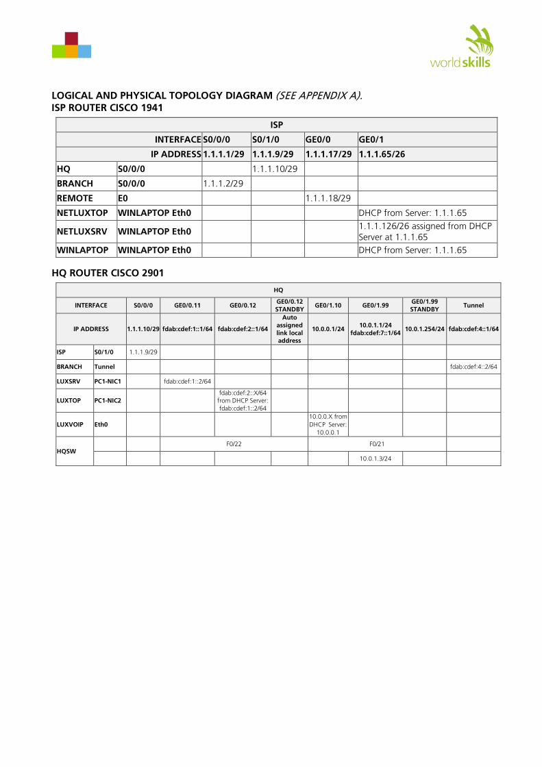
LOGICAL AND PHYSICAL TOPOLOGY DIAGRAM (SEE APPENDIX A). ISP ROUTER CISCO 1941
ISP
INTERFACE S0/0/0 S0/1/0 GE0/0 GE0/1
IP ADDRESS 1.1.1.1/29 1.1.1.9/29 1.1.1.17/29 1.1.1.65/26
HQ S0/0/0 1.1.1.10/29
BRANCH S0/0/0 1.1.1.2/29
REMOTE E0 1.1.1.18/29
NETLUXTOP WINLAPTOP Eth0 DHCP from Server: 1.1.1.65
NETLUXSRV WINLAPTOP Eth0 1.1.1.126/26 assigned from DHCP Server at 1.1.1.65
WINLAPTOP WINLAPTOP Eth0 DHCP from Server: 1.1.1.65
HQ ROUTER CISCO 2901
HQ
INTERFACE S0/0/0 GE0/0.11 GE0/0.12 GE0/0.12 STANDBY
GE0/1.10 GE0/1.99 GE0/1.99 STANDBY
Tunnel
IP ADDRESS 1.1.1.10/29 fdab:cdef:1::1/64 fdab:cdef:2::1/64
Auto assigned link local address
10.0.0.1/24 10.0.1.1/24 fdab:cdef:7::1/64
10.0.1.254/24 fdab:cdef:4::1/64
ISP S0/1/0 1.1.1.9/29
BRANCH Tunnel fdab:cdef:4::2/64
LUXSRV PC1-NIC1 fdab:cdef:1::2/64
LUXTOP PC1-NIC2 fdab:cdef:2::X/64 from DHCP Server: fdab:cdef:1::2/64
LUXVOIP Eth0 10.0.0.X from DHCPServer:
10.0.0.1
HQSW F0/22 F0/21
10.0.1.3/24
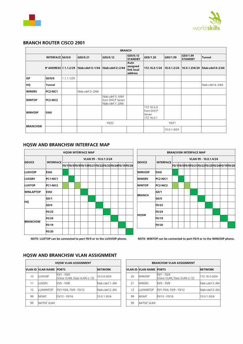
BRANCH ROUTER CISCO 2901
BRANCH
INTERFACE S0/0/0 GE0/0.21 GE0/0.12 GE0/0.12 STANDBY GE0/1.20 GE0/1.99 GE0/1.99
STANDBY Tunnel
IP ADDRESS 1.1.1.2/29 fdab:cdef:3::1/64 fdab:cdef:2::2/64
Auto assigned link local address
172.16.0.1/24 10.0.1.2/24 10.0.1.254/24 fdab:cdef:4::2/64
ISP S0/0/0 1.1.1.1/29
HQ Tunnel fdab:cdef:4::2/64
WINSRV PC2-NIC1 fdab:cdef:3::2/64
WINTOP PC2-NIC2 fdab:cdef:3::X/64 from DHCP Server: fdab:cdef:1::2/64
WINVOIP Eth0
172.16.0.X from DHCPServer: 172.16.0.1
BRANCHSW F0/22 F0/21
10.0.1.4/24
HQSW AND BRANCHSW INTERFACE MAP
HQSW INTERFACE MAP BRANCHSW INTERFACE MAP
DEVICE INTERFACE VLAN 99 - 10.0.1.3/24
DEVICE INTERFACE VLAN 99 - 10.0.1.4/24
F0/1 F0/5 F0/9 F0/13 F0/21 F0/22 F0/23 F0/24 F0/19 F0/20 F0/1 F0/5 F0/9 F0/21 F0/22 F0/23 F0/24 F0/19 F0/20
LUXVOIP Eth0 WINVOIP Eth0
LUXSRV PC1-NIC1 WINSRV PC2-NIC1
LUXTOP PC1-NIC2 WINTOP PC2-NIC2
WINLAPTOP Eth0 BRANCH
G0/1
HQ G0/1 G0/0
G0/0
HQSW
F0/23
BRANCHSW
F0/23 F0/24
F0/24 F0/19
F0/19 F0/20
F0/20
NOTE: LUXTOP can be connected to port F0/9 or to the LUXVOIP phone. NOTE: WINTOP can be connected to port F0/9 or to the WINVOIP phone.
HQSW AND BRANCHSW VLAN ASSIGNMENT
HQSW VLAN ASSIGNMENT BRANCHSW VLAN ASSIGNMENT
VLAN ID VLAN NAME PORTS NETWORK VLAN ID VLAN NAME PORTS NETWORK
10 LUXVOIP F0/1 - F0/4 (Voice VLAN; Data VLAN is 12) 10.0.0.0/24 20 WINVOIP
F0/1 - F0/4 (Voice VLAN; Data VLAN is 12) 172.16.0.0/24
11 LUXSRV F0/5 - F0/8 fdab:cdef:1::/64 21 WINSRV F0/5 - F0/8 fdab:cdef:3::/64
12 LUXWINTOP F0/1-F0/4, F0/9 - F0/12 fdab:cdef:2::/64 12 LUXWINTOP F0/1-F0/4, F0/9 - F0/12 fdab:cdef:2::/64
99 MGMT F0/13 - F0/16 10.0.1.0/24 99 MGMT F0/13 - F0/16 10.0.1.0/24
99 NATIVE VLAN 99 NATIVE VLAN

REMOTE ASA 5505
REMOTE
INTERFACE E0 E1 E2
IP ADDRESS 1.1.1.18/29 192.168.0.1/25 192.168.0.129/25
ISP G0/0 1.1.1.17/29
REMWINTOP PC2-NIC3 DHCP from Server: 192.168.0.1
DMZLUXSRV PC1-NIC3 192.168.0.130/25
VIRTUAL MACHINE TO NETWORK INTERFACE CARD MAP
PC1 NIC1 NIC2 NIC3
PC2 NIC1 NIC2 NIC3
WINLAPTOP Eth0 Eth0 Eth0
Bridge Bridge Bridge Bridge Bridge Bridge Bridge Bridge
LUXSRV Eth0 WINSRV Eth0 NETLUXTOP Eth0
LUXTOP Eth0 WINTOP Eth0 NETLUXSRV Eth0
DMZLUXSRV Eth0 REMWINTOP Eth0 WINLAPTOP Eth0
IPV4 / IPV6 MAP
IPv4 / IPv6 MAP
FQDN IP ADDRESSING
www * Private IPv4 Public IPv4 Private IPv6 Public IPv6
NETLUXSRV www.skills.com skills.com 1.1.1.126/26 2001:db8:0:1::1/64
DMZLUXSRV www.brazil.com brazil.com 192.168.0.130/25 1.1.1.19/29 2001:db8:0:1::2/64
WINSRV www.saopaulo.com saopaulo.com 172.17.0.1/24 fdab:cdef:3::2/64
LUXSRV www.rio.com rio.com 172.18.0.1/24 fdab:cdef:1::2/64
DNS SERVERS
DNS SERVERS
SERVER RECORD RECORD ADDRESS
ISP www.skills.com skills.com 1.1.1.126/26
www.brazil.com brazil.com 1.1.1.18/29
WINSRV
www.skills.com skills.com 2001:db8:0:1::1/64
www.brazil.com brazil.com 2001:db8:0:1::2/64
www.saopaulo.com saopaulo.com fdab:cdef:3::2/64
www.rio.com rio.com fdab:cdef:1::2/64
HQ www.saopaulo.com saopaulo.com 172.17.0.1/24
www.rio.com rio.com 172.18.0.1/24
NOTE: Forward all other requests to the ISP DNS server.

VOIP EXTENSION MAP
VOIP EXTENSION MAP
HOST User VOiP DEVICE EXTENSION CME SERVER
LUXVOIP Alice Cisco 7962 101, 104 HQ REMWINTOP Bob Cisco IPC 102, 104 HQ WINLAPTOP_1 Carol Cisco IPC 103 HQ WINVOIP John Cisco 7962 201 BRANCH
HOST IP ADDRESS MAP
HOST IP ADDRESS MAP
HOST IP ADDRESS / MASK DEFAULT GATEWAY DNS SERVER
NETLUXSRV 1.1.1.126/26 assigned from DHCP Server at 1.1.1.65 1.1.1.65 assigned from DHCP Server at 1.1.1.65 ISP
WINLAPTOP_1 1.1.1.X/26 assigned from DHCP Server at 1.1.1.65 1.1.1.65 assigned from DHCP Server at 1.1.1.65 ISP
NETLUXTOP 1.1.1.X/26 assigned from DHCP Server at 1.1.1.65 1.1.1.65 assigned from DHCP Server at 1.1.1.65 ISP
LUXVOIP 10.0.0.X from DHCPServer: 10.0.0.1 10.0.0.1 assigned from DHCP Server at 10.0.0.1
LUXSRV fdab:cdef:1::2/64 fdab:cdef:1::1/64 WINSRV
LUXTOP fdab:cdef:2::X/64 from DHCP Server: fdab:cdef:1::2/64 Automatic link local assigned by router WINSRV
WINLAPTOP_2 DHCP from Server: 10.0.1.3 10.0.1.X assigned from DHCP Server at 1.0.1.3 HQ
WINLAPTOP_2 DHCP from Server: fdab:cdef:7::1 Automatic link local assigned by router WINSRV
WINVOIP DHCP from Server: 172.16.0.1 172.16.0.1 assigned from DHCP Server at 172.16.0.1
WINSRV fdab:cdef:3::2/64 fdab:cdef:3::1/64 WINSRV
WINTOP fdab:cdef:2::X/64 from DHCP Server: fdab:cdef:1::2/64 Automatic link local assigned by router WINSRV
DMZLUXSRV 192.168.0.130/25 192.168.0.129/25 HQ
REMWINTOP 192.168.0.X from DHCP Server: 192.168.0.1 192.168.0.1 assigned from DHCP Server at 192.168.0.1 HQ
NOTE: WINLAPTOP_1 and WINLAPTOP_2 is the same physical machine, the laptop.
VTP AND SPANNING TREE INFORMATION
VTP INFORMATION SPANNING TREE INFORMATION FOR VLAN 99 SPANNING TREE INFORMATION FOR VLAN 12
VTP DOMAIN: skills.org PRIMARY ROOT BRIDGE HQSW PRIMARY ROOT BRIDGE BRANCHSW
VTP PASSWORD: Skills39 SECONDARY ROOT BRIDGE BRANCHSW SECONDARY ROOT BRIDGE HQSW
VTP SERVER: HQSW HQSW LINKS F0/23, F0/24 HQSW LINKS F0/19, F0/20
VTP CLIENT: BRANCHSW BRANCHSW LINKS F0/23, F0/24 BRANCHSW LINKS F0/19, F0/20
VLANS ALLOWED ON LINKS 99
NATIVE VLAN 99
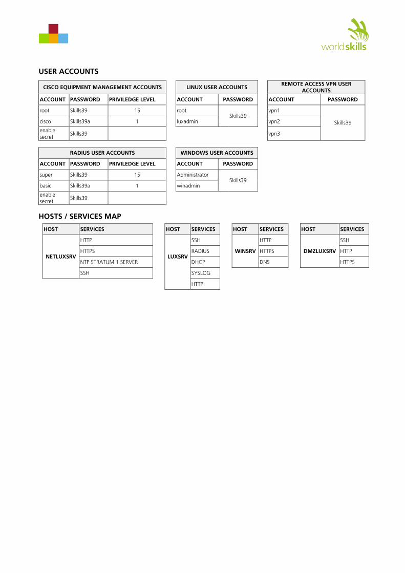
USER ACCOUNTS
HOSTS / SERVICES MAP
HOST SERVICES HOST SERVICES HOST SERVICES HOST SERVICES
NETLUXSRV
HTTP
LUXSRV
SSH
WINSRV
HTTP
DMZLUXSRV
SSH
HTTPS RADIUS HTTPS HTTP
NTP STRATUM 1 SERVER DHCP DNS HTTPS
SSH SYSLOG
HTTP
CISCO EQUIPMENT MANAGEMENT ACCOUNTS LINUX USER ACCOUNTS REMOTE ACCESS VPN USER
ACCOUNTS
ACCOUNT PASSWORD PRIVILEDGE LEVEL ACCOUNT PASSWORD ACCOUNT PASSWORD
root Skills39 15 root Skills39
vpn1
Skills39 cisco Skills39a 1 luxadmin vpn2
enable secret Skills39 vpn3
RADIUS USER ACCOUNTS WINDOWS USER ACCOUNTS
ACCOUNT PASSWORD PRIVILEDGE LEVEL ACCOUNT PASSWORD
super Skills39 15 Administrator Skills39
basic Skills39a 1 winadmin
enable secret Skills39

EIGRPv6 ROUTING OSPFv3 ROUTING
Catalyst 2960 SERIES
MODE
SYSTRPSMASTRSTATDUPLXSPEED
1
13X
14X
13 14 15 16 17 18 19 20 21 22
23X
24X
23 24
1X
2X
1 2 3 4 5 6 7 8 9 10
11X
12X
11 12
2
ISP
SYS ACT POE
I 100-240V~2-1A
50-60 Hz
Cisco 2900 Series
2901
CF 1 CF 0 ISM
EHWIC 0EHWIC 1EHWIC 2EHWIC 3
EN EN
CONSOLE
AUX
GE 0/1
S L
GE0/0
S L
USB1
0
PVDM1 PVDM0
S2
S0
S3
S1
HWIC-4TCONN
SYS ACT POE Cisco 1900 Series
SYS ACT POE
Cisco 1941 Series
O
I
PWR LNK4xPWR LNK5xPWR LNK6xPWR LNK7xLNK8x PWR LNK0xPWR LNK1xPWR LNK2xPWR LNK3x
HWICD9ESW
CF 1 CF 0 ISM/WLAN
HWIC2SHDSL EN L0 L1
SHDSL
SEE MANUALBEFORE INSTALLATION
EN EN
CONSOLE
AUX
GE 0/1
S L
GE0/0
S L
USB1
0
eHWIC 0eHWIC 1
HWIC2A/S CONN CONN
SERIAL 1
SERIAL 0
Catalyst 2960 SERIES
MODE
SYSTRPSMASTRSTATDUPLXSPEED
1
13X
14X
13 14 15 16 17 18 19 20 21 22
23X
24X
23 24
1X
2X
1 2 3 4 5 6 7 8 9 10
11X
12X
11 12
2
SYS ACT POE
I 100-240V~2-1A
50-60 Hz
Cisco 2900 Series
2901
CF 1 CF 0 ISM
EHWIC 0EHWIC 1EHWIC 2EHWIC 3
EN EN
CONSOLE
AUX
GE 0/1
S L
GE0/0
S L
USB1
0
PVDM1 PVDM0
S2
S0
S3
S1
HWIC-4TCONN
8 01234567
LUXVOIPExt:101, 104 LUXSRV – rio.com LUXTOP WINLAPTOP_2 WINVOIP
Ext: 201WINSRV – saopaulo.com WINTOP
DMZLUXSRV – brazil.com REMWINTOPCisco IPCExt: 102, 104
Option A
HQ BRANCH
F0/1 F0/5 F0/9 F0/13
F0/19
F0/20
F0/1 F0/5 F0/9
F0/21
E0
F0/23
G0/1 G0/0G0/1 G0/0
F0/21
F0/23
G0/1
G0/0
E1E2
REMOTE
HQSW BRANCHSW
F0/24 F0/24
G0/0 – 1.1.1.17/29
G0/1 – 1.1.1.65/26
S0/1/0 – 1.1.1.9/29
S0/0/0 – 1.1.1.10/29
S0/0/0 – 1.1.1.1/29
S0/0/0 – 1.1.1.2/29
VLAN2 - outside - 1.1.1.18/29
G0/0.11 – fdab:cdef:1::1/64
G0/0.12 – fdab:cdef:2::1/64
fdab:cdef:1::2/64fdab:cdef:2::X/64 from DHCP Server: fdab:cdef:1::2/64
10.0.0.X from DHCPServer: 10.0.0.1
G0/1.10 – 10.0.0.1/24
fdab:cdef:4::1/64 fdab:cdef:4::2/64IPv6 over IPv4 Point-to-Point GRE over IPSec Tunnel
Site-to-Site IKEv2 IPsec Tunnel between HQ and the ASA REMOTE site
REMOTE ACCESS VPN FOR INTERNET CLIENTSADDRESS POOL: 192.168.100.32 – 192.168.100.47
VLAN 9910.0.1.3/24
10.0.1.X from DHCP Server: 10.0.1.3
VLAN 9910.0.1.4/24
G0/0.21 – fdab:cdef:3::1/64
G0/0.12 – fdab:cdef:2::2/64G0/0.12 STANDBY – Auto assigned link local address
fdab:cdef:3::2/64172.16.0.X from DHCPServer: 172.16.0.1
G0/1.20 – 172.16.0.1/24
VLAN1 – inside – 192.168.0.1/25
DHCP from Server: 192.168.0.1192.168.0.130/25
VLAN3 – dmz – 192.168.0.129/25
HA ROUTING – STANDBY: Auto assigned link local address 2 PORT ETHERCHANNEL – STP – Trunk – Vlan 12 Only
PUBLIC INTERNET
Option A
NETLUXTOP WINLAPTOP_1Cisco IPC: 103
1.1.1.126/26 from DHCPServer: 1.1.1.65
fdab:cdef:3::/64fdab:cdef:4::/64
G0/1.99 – 10.0.1.1/24 G0/1.99 – 10.0.1.2/24
G0/1.99 STANDBY – 10.0.1.254/24 G0/1.99 STANDBY – 10.0.1.254/24
fdab:cdef:2::X/64 from DHCP Server: fdab:cdef:1::2/64
NETLUXSRV – skills.com
1.1.1.X from DHCPServer: 1.1.1.65
G0/0.12 STANDBY – Auto assigned link local address
fdab:cdef:1::2/64
HQ – OSPF Area 0with Authentication
fdab:cdef:4::/64
BRANCH–OSPF Area 1
HA ROUTING – STANDBY: 10.0.1.2542 PORT ETHERCHANNEL – STP – Trunk – Vlan 99 Only
Lo0 – fdab:cdef:5::1/64 Lo1 – fdab:cdef:6::1/64
BRANCH–OSPF Area 0 with Authentication
HQ EIGRP 100Routing with Authentication
BRANCH EIGRP 100Routing with Authentication
BRANCH EIGRP 200 Routing
fdab:cdef:3::/64
fdab:cdef:4::/64fdab:cdef:4::/64
fdab:cdef:1::/64 Lo0 – fdab:cdef:5::1/64
Lo1 – fdab:cdef:6::1/64
EIGRP 200 Redistribution into OSPF Area 0 and EIGRP 100
1.1.1.X from DHCPServer: 1.1.1.65
Option B
1 2ABC
3DEF
4 5JKL
6MNOGHI
7 8TUV
9WXYZPQRS
* 0OPER
#
7960CISCO IP PHONE
imessages directories
settingsservices
Option B
1 2ABC
3DEF
4 5JKL
6MNOGHI
7 8TUV
9WXYZPQRS
* 0OPER
#
7960CISCO IP PHONE
imessages directories
settingsservices
G0/1.99 – fdab:cdef:7::1/64
fdab:cdef:7::X/64 from DHCP Server: fdab:cdef:7::1/64
fdab:cdef:7::/64
fdab:cdef:7::/64
F0/19
F0/20
WSC2015_TP39_ModuleC_actual Version: 8.0 Date: 10.08.15 10 of 10