midlands state university feasibility study of …
TRANSCRIPT

MIDLANDS STATE UNIVERSITY
FEASIBILITY STUDY OF CONTROLLING AND
MONITORING AIRFIELD LIGHTING SYSTEM AT
JOSHUA MQABUKO NKOMO INTERNATIONAL
AIRPORT USING SCADA BASED TECHNOLOGY
BY
HUMBULANI CHOENI
R12344B
Submitted in partial fulfilment of the requirement for the degree of
Bachelor of Science in Telecommunications
Department of Physics and Applied Sciences in the
Faculty of Science and Technology at the
Midlands State University
GWERU
November, 2014
Supervisor: Mr A. Nechibvute Co-supervisor: Mrs Z.Mugabe

Page 1
Abstract
Joshua Mqabuko Nkomo International Airport was established in 1959 then known as Bulawayo
Airport. It is located in the second largest city of Zimbabwe, 25 km to the north of the City of
Kings- Bulawayo. JM Nkomo Airport is the second largest airport in Zimbabwe and boasts of
two runways which are 2,588 meters long by 45 metres wide and 1,347 metres by 30 metres
wide capable of handling wide bodied aircraft such as the Boeing 767. The airport operates 24
hours a day and is equipped with an instrument landing system in addition to airfield lighting
system. These lights aid an aircraft to align with the runway and land safely as it transit from
instrument approach to visual approach. At the present moment these light are controlled
manually, that is, putting them on/off and controlling their brilliance from the airfield ground
lighting room. During the night there are problems of controlling these lights when people have
knocked off and there will only be one duty air traffic controller who will be up in the control
tower.
The aim of this research is to carry out a feasibility study on the possibility of using a SCADA
based technology system for managing remote control airfield lights from the Air Traffic Control
centre by the duty controller. The system will increase customer satisfaction, both air traffic
controllers and pilots, enhance safety, and provide an accurate overview of the condition and
status of airfield lighting to the user controller.
More so, the SCADA system will store valuable information about alarms which might occur in
the system in the field. Such data becomes handy for efficient diagnosis of a faulty system and
provides hints to maintenance staff and help in restoration of the system when it breaks down.

Page 2
DECLARATION
I, HUMBULANI CHOENI, hereby declare that I am the sole author of this thesis. I authorize the
Midlands State University to lend this thesis to other institutions or individuals for the purpose of
scholarly research
Signature_______________________Date______________________________

Page 3
APPROVAL
This dissertation/thesis entitled “FEASIBILITY STUDYOF CONTROLLING AND
MONITORING AIRFIELD LIGHTING SYSTEM AT JMNKOMO INTERNATIONAL
AIRPORT USING SCADA BASED TECHNOLOGY” by HUMBULANI CHOENI meets the
regulations governing the award of the degree of Bachelor of Science in Telecommunications of
the Midlands State University, and is approved for its contribution to knowledge and literal
presentation.
Signature…………………………………………….
Date………………………………………………..

Page 4
Acknowledgement
I would like to express my sincere gratitude to the many people who have contributed to the
success of this research, in particular my supervisor, Mr A. Nechibvute and co-supervisor, Mrs
Z. Mugabe, for their support, encouragement and professional assistance throughout the work of
this research.
Special thanks go to all other Midlands State University staff members that I may have called
upon for their assistance. I would also want to extend my thanks to the Civil Aviation Authority
of Zimbabwe, Joshua Mqabuko Nkomo International Airport Air Navigation and Technical
Services department staff for their encouragement, support and assistance.
I would also want to extend my gratitude to my family for their love, patience and the unlimited
support they have given me.
Finally, I would like to thank the Midlands State University for accepting me in its graduate
program and motivated me to do this work.
R12344B Choeni Page 1
Table of Contents
CHAPTER 1 ............................................................................................................................. 4
INTRODUCTION.................................................................................................................... 4
1.1 Background ...................................................................................................................... 4
1.2 Overview of Airfield Lighting System............................................................................. 5
1.3 Overview of SCADA system ........................................................................................... 6
1.4 Research scope and Objectives ........................................................................................ 6
1.5 Methodology .................................................................................................................... 7
1.6 Chapter summaries ........................................................................................................... 7
CHAPTER 2 ............................................................................................................................. 8
LITERATURE REVIEW AND THEORETICAL ASPECTS .......................................... 8
2.1 Introduction ...................................................................................................................... 8
2.2 Overview of Airfield Lighting System............................................................................. 8
2.2.1 Precision Approach Path Indicator (PAPI). ............................................................. 10
2.2.2 Runway Edge Light Systems ................................................................................... 11
2.2.3 Approach lighting system ........................................................................................ 11
2.2.4 Taxiway lights ......................................................................................................... 12
2.2.5 Threshold lights ....................................................................................................... 12
2.3 SCADA Fundamentals ................................................................................................... 13
2.3.1 Functions of SCADA............................................................................................... 13
2.3.2 SCADA system components ................................................................................... 13
2.4 SCADA Systems deployment ........................................................................................ 20
2.4.1 Twisted-pair copper cable ....................................................................................... 21
2.4.2 Coaxial cable ........................................................................................................... 22
2.4.3 Fibre Optic Cable..................................................................................................... 23
2.4.4 Leased Telephone Lines .......................................................................................... 24
2.4.5 Very High Frequency Radio .................................................................................... 24
2.4.6 Ultra High Frequency Radio .................................................................................... 25
CHAPTER 3 ........................................................................................................................... 27
METHODOLOGY ................................................................................................................ 27
3.1 Introduction .................................................................................................................... 27
3.2 The assessment of quality of airfield lighting system from the perspective of users ..... 27
3.3 Technical testing and evaluation of the current airfield system ..................................... 28
R12344B Choeni Page 2
3.4 Case studies where SCADA based technology is used .................................................. 30
3.4.1 Case study 1: Darwin Royal Air Force Base [18] ................................................... 30
3.4.2 Case study 2: Cape Town International Airport upgrades [19] ............................... 31
3.4.3 Case study 3: Upgrades of Sydney Airport [20] ...................................................... 31
CHAPTER 4 ........................................................................................................................... 33
RESULTS AND ANALYSIS ................................................................................................ 33
4.1 Introduction .................................................................................................................... 33
4.2 Customer interview results and analysis ........................................................................ 33
4.3 Results from system measurements ............................................................................... 34
4.4 Results of case studies .................................................................................................... 37
CHAPTER 5 ........................................................................................................................... 39
CONCLUSIONS AND RECOMMENDATIONS ............................................................... 39
5.1 Introduction .................................................................................................................... 39
5.2 Conclusions .................................................................................................................... 39
5.3 Recommendations and suggestions ................................................................................ 40
References ............................................................................................................................... 41
Appendix A .......................................................................................................................... 43
Appendix B .......................................................................................................................... 44

R12344B Choeni Page 3

R12344B Choeni Page 4
CHAPTER 1
INTRODUCTION
1.1 Background
Joshua Mqabuko Nkomo International Airport was established in 1959 then known as
Bulawayo Airport. It is located in the second largest city of Zimbabwe, 25 km to the north of
the City of Kings- Bulawayo. JM Nkomo Airport is the second largest airport in Zimbabwe
and boasts of two runways which are 2,588 meters long by 45metres wide and 1,347 metres
by 30 metres wide capable of handling wide bodied aircraft such as the Boeing 767. The
airport operates 24hours a day, implying there can be flying into and out of the airport at
night, and is equipped with a Category 1 instrument landing system in addition to airfield
lighting system. These airfield lights aid an aircraft to align with the runway and land safely
as it transit from instrument approach to visual approach in both clear and poor weather
conditions. The airfield lighting system at the airport was installed in 1959 when the airport
was first operationalized. The system comprised of a control panel which was used to
interface with Air Traffic Controllers. The panel had of an array of ON/OFF switches, rotary
switches and pushbuttons. It was connected to the various airfield lighting devices using
custom-made relay or contactor hardwired configurations. The system was upgraded over the
years to have some remote control of the lights in compliance with ICAO Annex 14 [1].
This upgraded system broke down in 2003 and since then airfield lighting has been manually
controlled, that is, putting them on/off and controlling their brilliance from the airfield ground
lighting room. The lack of remote control of these airfield lights is the major source of the
problem. According to the International Civil Aviation Organisation (ICAO) Standards and
Recommended Practices (SARPs), these lights are supposed to be automatically monitored so
as to provide real-time indication of any faults which might affect the control functions and
the information is to be automatically relayed to the air traffic service unit [1]. During night
operations there are problems of controlling these lights when people have knocked off and

R12344B Choeni Page 5
there will only be one duty air traffic controller who will be up in the control tower and is
distant from the Airfield Ground Lighting (AGL) room. Also ICAO recommends that where
high-intensity lighting system is provided, a suitable intensity control should be incorporated
to allow for adjustment of the light intensity to meet the prevailing conditions [1].
The researcher was motivated after realising that the runway lights control at JMNkomo
Airport was currently done using a manual system of switching ON and OFF of the lights by
personnel on duty during the day just before knock off time. It was observed that these lights
were at times switched on too early to avoid forgetting to put them on after sunset. The same
lights would only be switched off by personnel reporting for duty the following day. Under
normal conditions, these lights are supposed to be switched on and off by duty air traffic
controller. If personnel on duty forget to put them off when they report for duty, the lights
would be left on during the day at full brilliance. All these irregularities in controlling airfield
lights results in the Civil Aviation Authority of Zimbabwe incurring unnecessarily high
electricity bills. Also given the power rating of the individual bulbs used for apron and
runway lighting there is a significant cumulative contribution to global warming which is an
issue of great concern to the society these days.
In light of the challenges of the current manual system, it is proposed that a novel system
based on Supervisory Control And Data Acquisition (SCADA) technology is a possible
solution. It is along this thrust that the current research is established.
1.2 Overview of Airfield Lighting System
Airfield lighting system typically comprises of approach lights, runway centre-line lights,
runway-edge lights, taxiway centre-line lights, runway-end lights, runway threshold lights,
precision approach path indicator (PAPI) lights, and many other different lighting systems.
Airfield lighting system is critical in that it provides basic visual guidance to aircraft in their
final landing phase in clear or poor visibility weather conditions and night landings. They are

R12344B Choeni Page 6
a means of aiding aircraft transit from instrument approach to visual approach in the final
phase of landing. Airfield lighting is a configuration of signal lights starting at the landing
threshold and extending into the approach area up to a maximum distance of 900 metres
depending on the runway[1].
1.3 Overview of SCADA system
SCADA is an acronym for Supervisory Control And Data Acquisition. As implied by the
name, it does not offer full control of the system, but rather it focuses on the supervisory level
[4]. SCADA systems normally comprise of networks, switching devices, electronic devices,
sensors, which enable monitoring, control and management of processes locally or remotely.
These processes comprise of plants or equipment in industries such as water and waste
control, telecommunications, energy, oil and gas refining and transportation. These systems
encompass an exchange of data between the central host computer and a number of Remote
Terminal Units (RTUs), and also between the central host computer and operator terminals.
A SCADA system collects information, analyses data and generates alarms which are sent to
different locations and the information is displayed in an organized manner. SCADA systems
are normally geographically dispersed and traditionally linked through the public telephone
line system for controlling purposes, but modern systems can be made to be part of the
corporate Local Area Network (LAN)/Wide Area Network (WAN) infrastructure. Also
modern trends find wireless technologies being employed for the purposes of monitoring.
As a way of automating airfield lighting systems SCADA based technology is central to these
efforts. The main advantages of incorporating SCADA technology are the overall reduction
in operational and maintenance costs, improvement in system efficiency and performance. In
addition SCADA based systems reduce man-hours required for troubleshooting.
1.4 Research scope and Objectives
To technical test and document the current performance and limitations of the

R12344B Choeni Page 7
manual airfield lighting system at JMNkomo airport.
To thoroughly analyse the opportunities presented by SCADA in alleviating the
current challenges
To propose a SCADA based system based on case studies.
1.5 Methodology
To achieve the objectives of this research, the following will be undertaken.
Literature review and study of existing systems in other applications so as to
understand the concepts of SCADA in controlling industrial processes and identify
knowledge gaps in applications of the same technology in aviation lighting systems
Measure the actual current outputs of the constant current regulators (CCRs) over a
period of time and compare results with technical specifications given by
manufacturer.
Use questionnaires to get opinions of users of airfield lighting system, who in this
case are pilots.
1.6 Chapter summaries
Chapter 1 presents an introduction to the research.
Chapter 2 discusses literature review and theoretical aspects.
Chapter 3 presents the methodology.
Chapter 4 presents the results and analysis.
Chapter 5 presents the conclusions and suggestions for other future areas of research.
R12344B Choeni Page 8
CHAPTER 2
LITERATURE REVIEW AND THEORETICAL
ASPECTS
2.1 Introduction
This chapter explains the overview of airfield lighting systems and the general architecture of
the SCADA system and some techniques of linking up the master terminal and the remote
PLC/RTU systems. This is important for the researcher so as to have a full understanding of
the theoretical aspects of the general system.
2.2 Overview of Airfield Lighting System
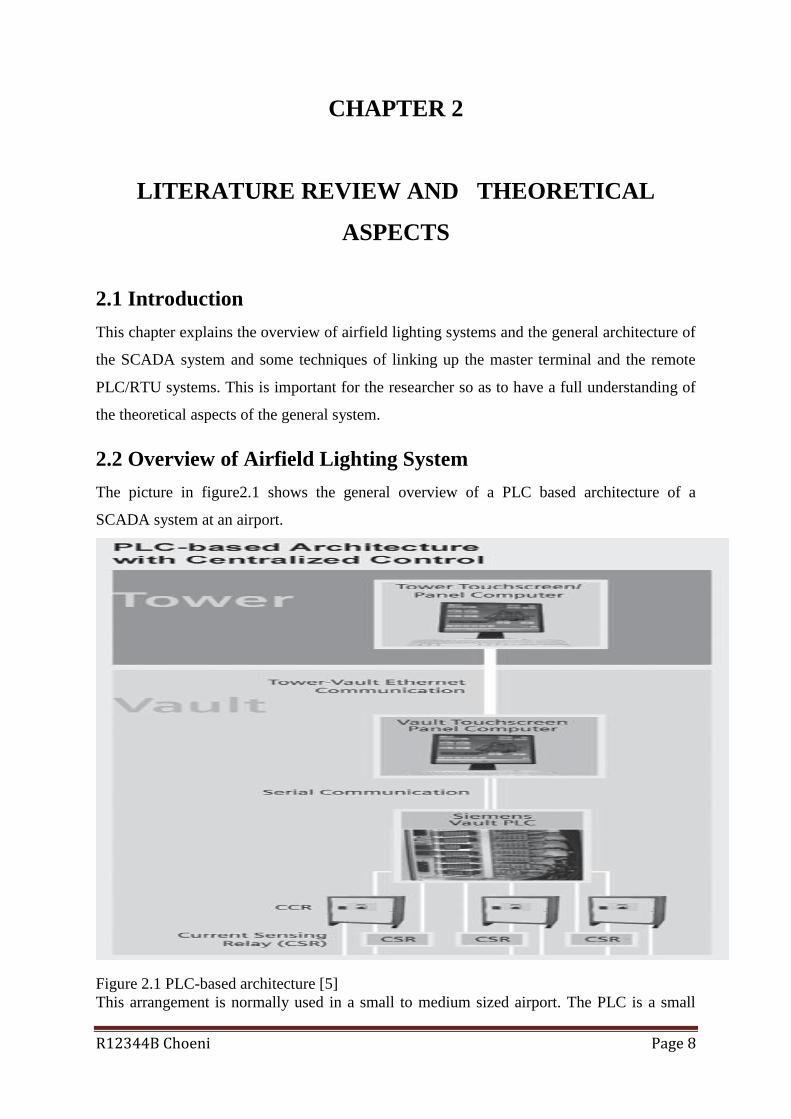
The picture in figure2.1 shows the general overview of a PLC based architecture of a
SCADA system at an airport.
Figure 2.1 PLC-based architecture [5]
This arrangement is normally used in a small to medium sized airport. The PLC is a small

R12344B Choeni Page 9
computer which is employed to automate the controlling and monitoring of the airfield
systems [6]. By design it can withstand large temperature ranges dirty and dusty environment
conditions. In general an airfield lighting control system comprises of ATC tower touch
screen computer which serves as both a workstation providing graphical user interface to
Controllers and a server, a modem, a PLC and another modem in the AGL room, and a
number of CCRs which actual regulate the current to the lights in the field. The airfield
lighting equipment is interfaced to the PLC via I/O modules. The PLC output modules are
connected to the remote control of the airfield lighting system, and input modules are linked
to the monitoring devices such as CCRs so as to accomplish ON/OFF monitoring. This setup
is diagrammatical shown below.
ATC
Tower
AGL room
Figure 2.2 Typical layout of a PLC based SCADA architecture
The controller selects the system to be put on from the touch screen and the signal is sent via
the modem to the remote modem which is hooked to the PLC. The PLC then sends the signal
to the respective CCR which switches on the lighting system. For brilliance control the
controller also selects a level of brilliance required from the touch screen by touching B1, B2,
B3, B4, and B5 selection button which corresponds to a certain level of current sent to the
CCR and thereby control the level of brightness of the lights.
ALCS gives touch screen facilities for the control and monitoring of approach, runway,
taxiway, and apron lighting functions as shown in figure 2.3.
PC Industrial
Touchscreen
Modem
Modem
PLCs

R12344B Choeni Page 10
Figure 2.3: ALCMS maintenance example of monitoring airfield lighting [7]
Each of these circuits can be switched on individually and their related brilliance level can be
adjusted accordingly. Depending on prevailing visibility conditions for day or night
operations each function can be programmable to default settings in compliance with ICAO
standards and recommended practices [8], thus giving correct and uniform light to
approaching aircraft.
The infrastructure of airfield lighting includes approach lights, runway-edge and taxiway-
edge lights, precision approach path indicator (PAPI), threshold lighting, airfield guidance
marking signs, and apron area flood lights.
2.2.1 Precision Approach Path Indicator (PAPI).
The precision approach path indicator (PAPI) comprises of lights installed in a single row of
four light units on each side of the approach. These lights are visible from an aerial slant
distance of 8 kilometres in daylight and up to 30 kilometres at night [8]. They provide the
visual guidance of aircraft on the glide path of the runway. The PAPI provides a visual glide

R12344B Choeni Page 11
path which is obstruction free within plus or minus 10 degrees of the extended centreline of
the runway. Using the PAPI to descend can be initiated only when the aircraft is visually in
line with the runway centre-line. PAPI lights are installed normally to the left side of the
runway, and a typical installation of a PAPI system is shown in figure 2.4 below.
Precision Approach Path Indicator (PAPI)
Figure 2.4: Precision Approach Path Indicator [8]
2.2.2 Runway Edge Light Systems
Runway edge-lights are installed along the full length of the runway in two parallel rows to
indicate an outline of the edges of the runways during the night or in reduced visibility
conditions times. The lighting systems are classified according to the brightness and/or
intensity they are capable of producing. They can be High Intensity Runway Lights (HIRL),
Medium Intensity Runway Lights (MIRL), and the Low Intensity Runway Lights (LIRL).
The HIRL and MIRL systems should have variable brilliance controls, whereas the LIRLs
have one intensity setting.
2.2.3 Approach lighting system
This is a sequence of high-intensity lighting arrangement stretching for about 900 metres
before the beginning of the runway. These lights help the pilots check if the aircraft is
correctly aligned to the centreline of the runway. They give the way to the touch down zone

R12344B Choeni Page 12
lights from the threshold of the runway. They are mounted on pedestals of varying heights to
compensate for the irregularities of the ground so that they are all at the same height
2.2.4 Taxiway lights
Taxiway edge lights provide visual aid to taxing aircraft under low visibility operations.
Taxiway centreline lights are green in colour. Pilots have to manoeuvre their aircrafts on
taxiways to and from the terminal area either after a landing or on their way to take off. It is
critical to provide adequate lighting for night operations or poor visibility conditions along
taxiways so as to expedite efficient movements of aircraft.
2.2.5 Threshold lights
The threshold is identified by a complete line of green lights which extends across the full
width of the runway. Identification of the threshold is a major factor for the pilot in making a
decision when they get to the decision height level either to land or abort and go round and
come for the second attempt. For this reason lighting of the threshold is provided by special
lights that are of semi flash type.
Figure 2.5 below shows typical airfield lighting of an airport comprising of PAPIs, runway
edge lights, approach lights and touch down threshold lights.
Figure 2.5: Typical airfield lighting system of an airport [9]

R12344B Choeni Page 13
Electrical power to these lighting circuits is distributed by high tension cables buried
underground from electrical vaults located in the airfield ground lighting (AGL) room. The
AGL room contain the constant current regulators (CCRs) for the lighting circuits which are
supposed to be controlled remotely by an Airfield Lighting Control & Monitoring System
(ALCMS). The status of lighting circuits is supposed to be sent to a Supervisory Control and
Data Acquisition (SCADA) console in the Air Traffic Control centre, so that it provides
operators with a display interface from which they can control the airfield lighting circuits.
2.3 SCADA Fundamentals
2.3.1 Functions of SCADA
A SCADA system has basically two functions which are to display information about the
current operating conditions of a remote process in an informative and graphical interface,
and to enable supervisory control of the plant by operators. Advanced and complex systems
may give extra features such as trending of data to allow past operations of the plant to be
recorded for future references and assistance in fault diagnosis.
A SCADA application gives the operator a graphical user interface (GUI) which enables
monitoring and controlling of processes taking place in a remote site. The system enables the
operator to attain the complete knowledge of the system in a single room by means of
displays.
2.3.2 SCADA system components
A general SCADA system deployed in an industry may consist of the following:
A central host computer which acts as the main server. This is the main part of the
SCADA system and is also referred to as a SCADA Centre or Master Terminal Unit
(MTU)
Field data interface device(s) which are typically RTUs, or PLCs. These are used to
interface to field sensors and local control switches and relays.
A communications link system which enables data exchanges between PLCs/RTUs
and the server computer in the SCADA central host. This link infrastructure can be

R12344B Choeni Page 14
wireless, twisted pair cable, coaxial cable, optic fibre cable, etc., or any combination
of the above.
Standard or proprietary software generally referred to as Human Machine Interface
(HMI) software or Man Machine Interface (MMI) software. This provides the central
server and operator terminals with application software, support the whole
communications system infrastructure, and monitor/control remotely located field
data interface devices such as PLCs and RTUs.
Figure 2.6 below shows a typical SCADA system.
Figure 2.6: Generic SCADA system network [10]
2.3.2.1 Central Host Computer
The Master Terminal Unit is normally a computer which provide operator interface to the
SCADA system. The MTU processes received information from and sent to RTU sites and
present it to the users in an easy and human understandable form. User terminals are linked to
the central host computer by a local area network so that the displays and the associated data
can easily be viewed by operators. Modern SCADA systems use high resolution computer
graphics to mimic screen of the remote site and are usually touchscreen types.
The tremendous increase in computer networking has resulted in SCADA systems being
incorporated into the corporate networks. Actually SCADA systems can now reside in main
computer servers which are used for normal office applications.

R12344B Choeni Page 15
2.3.2.2 Field Data Interface Devices
Field data interface devices are the "eyes and ears" of a SCADA system. Information sent to
and from field data interface devices is changed into a form which is compatible with the
language used by the SCADA system before realising any automation or remote monitoring.
To realise this, some electronic form of field data interface is required in the make of RTUs
(Remote Telemetry Units), which change received electronic signals from field interface
devices into a communication protocol which is then used to transmit the data over a given
communication channel.
Automation of field data interface devices instructions are normally stored locally so as not to
overload the limited bandwidth of communications links connecting the SCADA central host
computer and the remote field data interface devices. These instructions are held within the
PLCs itself. A PLC can be defined as a device which is used to automate control and
monitoring of industrial processes. PLCs are normally connected directly to field data
interface devices and they incorporate programmed data which can be in the form of logical
procedures that are executed when certain field conditions occur.
PLCs origin can be traced to the automation industry, and in that setup there was no need to
connect them to communications channels as they were deployed as a replacement of relay
logic technology. On the other hand, SCADA systems originated in telemetry applications,
where there was only need to know some basic information from a given remote source.
RTUs connected to such systems did not need control programming since the local control
algorithm was stored in the relay switching logic.
As PLCs were adopted to replace relay switching logic control systems, telemetry was now
used in conjunction with PLCs at these remote sites. This resulted in the need to influence
programs inside the PLC through some form of remote signal, which in essence is the
"Supervisory Control" component of the SCADA. When a local control program is required
it is possible to store the program inside the RTU itself which performs the control function
within the device. PLCs include communications modules which report the status of the
control program to a computer directly plugged into the PLC or to a remotely located
computer through a communication medium like a telephone line.
Due to the above developments, there is blurred difference between PLCs and RTUs such
that this terminology can be used interchangeably.

R12344B Choeni Page 16
2.3.2.3 Communications Network
The communications network provides a means of transferring data between the RTUs in the
field and the central host computer servers. Communication networks can be built in various
ways, and some examples of the topologies used in SCADA systems are shown in figure 2.7
below.
Figure 2.7: Typical network topologies [11]
The communication network is the actual equipment used to send data to and from remote
sites. Various medium can be used to link the central host servers and remote sites, and
typical examples include cable, telephone, or radio.
A common way of transferring digital data in communication is either through parallel or
serial transmission.
Serial data transmission is where one bit is sent at a time from the transmitter to receiver and
parallel transmission is where several data bits or the whole byte are sent simultaneously over
parallel channels. Figure 2.8 shows the difference between the two modes.

R12344B Choeni Page 17
Figure 2.8: The basics of the parallel and serial transmission [11]
Parallel transmission is applied over very short distances, typically within a computer itself. It
is a quick way of transferring data but disadvantage of using more wires which then makes
the error handling very difficult in long distances and therefore increase in costs.
Serial transmission on the other hand is used to send data between two computer node
systems, especially over long distances. Serial transmission can either be synchronous or
asynchronous. In the synchronous transmission type, groups of data bits are grouped into
frames and then transmitted continuously to the receiver. In asynchronous transmission, data
bits groups are transferred as independent units without any data link synchronization.
Start/stop bits are used to maintain the physical bit level synchronization once detected.
In a factory setup cable connections can be utilised but such a setup will not be practical for
geographical spaced areas due cabling costs. The use of leased or dial-up telephone lines is
very economic for geographical spaced systems. The leased-line option is normally used for
systems which require on-line connections with remote sites. Dial-up modems are used with
systems which require regular updates at fixed intervals whereby a host dials a contact
number for a remote station so as to get the latest data and also send relevant commands.
In situations where remote stations are not easily reachable by physical telephone lines, radio
link use provides a viable alternative and modems will be used to link these remote stations to
the host.
SCADA networks are historically dedicated networks, but with the advent of corporate
networks such as LANs and WANs there is a possibility of integrating SCADA local area

R12344B Choeni Page 18
networks into these networks. The benefit of such a setup is that there would be no extra
investment in a separate network for the SCADA operator terminals, but the associated
disadvantage would be vulnerability of the network to attacks.
In an airport setting, fibre optic cable can be used as the main communications medium
linking the control centre to the remote airfield ground lighting site. Whilst fibre-based
communications is considered reliable it has its own disadvantages. Remote airfield
conditions may be such that:
Construction works on the airside can disturb communications and thus the whole
operations of the airfield.
Cable ducts for communications are buried underneath the concrete runway and
taxiways slabs, and are very expensive to install and maintain.
Optic fibre networks for redundancy normally run parallel to the main line, and are
exposed to the same risks, especially when ducts are snapped by excavation works.
To overcome the above shortcomings use of an independent wireless redundant system can
be employed. Airports are usually a dynamic entity, with taxiway and runway expansions
and rehabilitation of surfaces on-going. Maintenance and constructions on the airside is
always on going. If fibre optic cable is laid all around, there is a high risk that the fibre can be
disturbed during construction work thereby rendering the control system to be unavailable for
some period. Wireless solutions can be used with their associated advantages as back-up to
the fibre lines. The reduction of costs associated with the installation, replacement, and
maintenance of fibre can be major drivers, but the assurance of increased uptime by
implementing an independent backup communication system is even more attractive.
Wireless communications has its own challenges, such as the challenge of pinpointing a
point of interference, lack of control of who else will be in the spectrum in future, especially
with the use of the free 2.4GHz frequency.
2.3.2.4 Operator Workstations and Software Components
Operator workstations are simple computer terminals linked with the SCADA central host
computer. The central host computer is a server for the SCADA application, and operator
terminals are just clients which request and send information to the central host computer
depending on the requests and actions of operators.
The software used in the system is the most important aspect of any SCADA system and this
software is the Man Machine Interface/Human Machine Interface (MMI/HMI) package.

R12344B Choeni Page 19
Typical SCADA systems use proprietary software on which the systems are developed. The
disadvantage of proprietary software is that it is meant for a specific hardware platform which
normally is not compatible with software/hardware from other competing suppliers.
Commercial off-the-shelf (COTS) software usually has the advantage of flexibility, and
interfaces with different types of hardware and software.
Proprietary software focuses much on control functionality and processes, while the emphasis
of COTS software is on interfacing with a variety of other equipment and instrumentation.
Typically software used in a SCADA system is:
• Operating system for the central host computer, which is used to control hardware of
the central host computer.
• Operating system for operator terminal which is also used to control the central host
computer hardware and is usually the same as the central host computer operating
system.
• Application software for the central host computer which handles exchange of data
the RTUs and the central host. It also gives the graphical user interface which offers
site mimic screens, alarm pages, trend pages, and control functions.
• Operator terminal application, which enables operators to access information
available on the central host computer application.
• Drivers for the communications protocol are usually based within the central host
and the RTUs, and are necessary to control translation and interpretation of the data
between ends of the communications links in the system. The protocol drivers prepare
the data for use either at the field devices or the central host end of the system.
• Communications network management software is used to control the
communications network and enable them to be monitored for failures and
performance.
• Software for RTU automation enables engineering staff to maintain and configure
the application inside the RTUs (or PLCs).
2.3.2.5 Hardware architecture
Constant current regulators (CCRs) in the airfield ground lighting (AGL) room are the remote
site equipment which should be linked to the main control room which is proposed to be at
the Air Traffic Control tower. The tower is chosen because of being the tallest structure at the
airport and it is where the controllers are housed. Also by virtue of being the tallest structure
it is preferable for wireless communications between the AGL room and the main control
room.

R12344B Choeni Page 20
The AGL contains CCRs connected to lighting system in the airfield which need to be
controlled and monitored. The CCRs are connected to the PLCs and RTUs. These process
controllers control CCRs, gather data from airfield lights and subsequently provide data to the
main control centre, where SCADA servers are housed. These servers store data from PLCs
and RTUs, provides HMI for operators, and send alarms to operators. The links between the
process controllers and SCADA servers is achieved using different techniques which are
discussed later.
2.3.2.6 Software System
For a SCADA system to function it needs a protocol for transmitting data. SCADA
communication protocols define the method by which data is transmitted along a
communication link [11]. Data representation in a SCADA network is identified by a unique
addressing scheme. The addressing system is such that it correlates with the master station
database. Each protocol has two sets of message. One set being the master protocol which
contains master station statements for initiation or response and the other set is the RTU
protocol, which contains statements which an RTU can respond to and initiate.
2.4 SCADA Systems deployment
Implementation of SCADA systems can be achieved in various ways. Before rolling out a
SCADA system it is necessary to determine system function performance. There are a
number of options in creating such a system, which might mean employing different methods
complimenting each other. The various ways of deploying SCADA systems are briefly
discussed below, including their advantages and disadvantages.

R12344B Choeni Page 21
2.4.1 Twisted-pair copper cable
The twisted-pair cable is the cheapest and most popular medium used in telecommunications
and has been in existence for quite some time. The cable has a number of insulated pairs of
copper conductor as shown in figure 2.9.
Figure 2.9: Twisted pair cable illustration [12]
Overhead twisted pair cables can be used for an installation within the company’s premises if
it has its own distribution poles from which the cables could be suspended. In other
installations cables can be underground in ducts. Table 2.1 shows advantages and
disadvantages of the twisted-pair cable.
Table 2.1 Twisted-Pair Advantages/Disadvantages [13]

R12344B Choeni Page 22
2.4.2 Coaxial cable
A coaxial cable consists of a solid copper or copper-clad-steel inner conductor surrounded by
a non-conductive dielectric insulating material. The dielectric material is surrounded by foil
shield and/or copper braid which form an outer conductor which acts as a shield against
electromagnetic interference (EMI). The outer conductor is encased in a polyvinyl chloride
(PVC) insulation jacket as shown in figure 2.10.
Figure 2.10: Coaxial cable construction [14]
Coaxial cables are capable of transmitting high frequency signals with minimum attenuation
when compared to twisted pair wires. Coaxial cables can be installed by directly burying
them underground or by overhead hanging them on poles. Coaxial cables are capable of
supporting data, voice and interoffice networking. Table 2.2 shows the advantages and
disadvantages of coaxial cable.

R12344B Choeni Page 23
Table 2.2: Coaxial Cable Advantages/Disadvantages [13]
2.4.3 Fibre Optic Cable
Fibre optic technology has tremendously improved greatly since its inception to a point
where fibre cables have less than 0.3 dB/km losses. Such small magnitude losses and the
developments in laser and optical detectors, has enabled designers to use fibre optic cables
for distances of up to 140 km or greater without any repeaters.
An optical fibre consists of an inner core, a cladding and a plastic jacket which physically
protects the fibre as illustrated in figure 2.11.
Figure 2.11: Basic construction of a Fibre Optic Cable [15]
Two common types of fibres in use are the multi-mode graded index and the single-mode
step index fibre. Single-mode fibres have the advantage of supporting high transmission
speeds than the multi-mode fibre.
Optical fibre support communication services such as voice, low speed data, SCADA links,
telemetering, and video conferencing. Optical fibre cables have aluminium tape or steel-wire
armours and polyethylene outer jackets for extra protection. The inner core is constructed in
such a way as to accommodate the mechanical characteristics of the fibres which are placed
loosely in semi-rigid tubes to take the mechanical stress. Table 2.3 gives the fibre optic cable
advantages and disadvantages.
R12344B Choeni Page 24
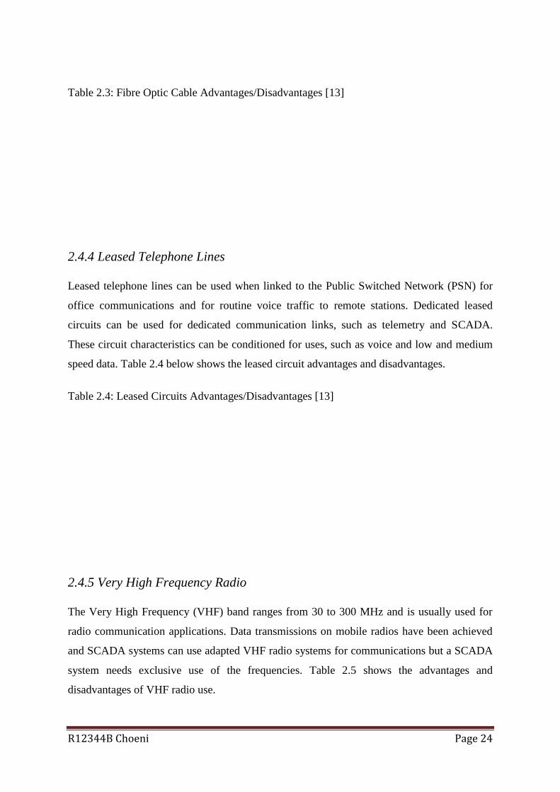
Table 2.3: Fibre Optic Cable Advantages/Disadvantages [13]
2.4.4 Leased Telephone Lines
Leased telephone lines can be used when linked to the Public Switched Network (PSN) for
office communications and for routine voice traffic to remote stations. Dedicated leased
circuits can be used for dedicated communication links, such as telemetry and SCADA.
These circuit characteristics can be conditioned for uses, such as voice and low and medium
speed data. Table 2.4 below shows the leased circuit advantages and disadvantages.
Table 2.4: Leased Circuits Advantages/Disadvantages [13]
2.4.5 Very High Frequency Radio
The Very High Frequency (VHF) band ranges from 30 to 300 MHz and is usually used for
radio communication applications. Data transmissions on mobile radios have been achieved
and SCADA systems can use adapted VHF radio systems for communications but a SCADA
system needs exclusive use of the frequencies. Table 2.5 shows the advantages and
disadvantages of VHF radio use.

R12344B Choeni Page 25
Table 2.5: VHF Radio Advantages/Disadvantages [13]
2.4.6 Ultra High Frequency Radio
The Ultra High Frequency (UHF) band ranges from 300 to 3000 MHz.
UHF systems can be Point-To-Point (PTP), Point-To-Multipoint (PTM), Trunked Mobile
Radio, or spread spectrum systems. The PTM systems are also known as Multiple Address
Radio Systems (MARS). Typical applications of spread spectrum systems include the 802.11
a/b/g networks.
2.4.6.1 Point-to-Point
Point-to-point communications is usually used for SCADA links from the master station to
individual substations. Table 2.6 shows the Point-To-Point UHF radio system advantages and
disadvantages.
Table 2.6: Point-to-Point UHF Radio Advantages/Disadvantages [13]
R12344B Choeni Page 26
2.4.6.2 Multiple Address Radio Systems
A Multiple Address Radio System (MARS) typically consists of a single Master Station
transmitting an omni-directional signal to fixed remote stations. The 400/900 MHz MARS
Radio is a single channel system that communicates with each of its remote stations in
sequence. Examples of services which are supported by MARS are SCADA, Telemetry/Data
Reporting, and limited basis voice. Table 2.7 shows MARS advantages and disadvantages.
Table 2.7: MARS UHF Radio Advantages/Disadvantages [13]
2.4.6.3 Spread Spectrum Radio
Spread spectrum radios can be operated in the 2.4GHz and 5.4 GHz band without licenses.
This resulted in the development of packet type radio networks for data systems, which are
suitable for Digital Multiple System (DMS) applications, such as Distribution Automation.
Table 2.8 shows the Spread Spectrum Radio System advantages and disadvantages.
Table 2.8: Spread Spectrum Radio Advantages/Disadvantages [13]

R12344B Choeni Page 27
CHAPTER 3
METHODOLOGY
3.1 Introduction
This chapter gives an account of the methodology adopted in carrying out the research work
so as to meet the set objectives. The chapter also gives details of the steps and techniques
used to determine which data source to use. The chapter analyses the research methods used
in the study. It will further look at the data acquisition and manipulation of the sourced data.
3.2 The assessment of quality of airfield lighting system from the
perspective of users
The key users of an airfield lighting system at an airport are airline pilots and private pilots.
In the assessment of quality of airfield lighting system service a sample of experienced pilots
who frequently fly into JMNkomo and the region were interviewed. A copy of the
questionnaire used to extract information from these pilots is attached Appendix A.
In this survey ten pilots were chosen and the criteria used were purely experience and
exposure to other airfield lighting systems in the region. For the sake of confidentiality and
professional reasons the names of the pilots in question will not be shown. Table 3.1 below
shows the experience of each of the pilots interviewed in the survey.
In the survey, 80 % of the population hold the rank of captain and the remaining 20 % are
first/second officers. All the pilots fly the short-haul within the region.

R12344B Choeni Page 28
Table 3.1 Experience of the individual pilots interviewed in the survey
Pilot Total number of
flying hours
Frequency of flying to
JMNkomo/month
Frequency of flying to
the region/month
Role of pilot in
the aircraft
Pilot #1 5565 15 4 Captain
Pilot #2 8750 20 4 Captain
Pilot #3 6900 6 16 Captain
Pilot #4 2760 8 12 1st Officer
Pilot #5 4500 12 12 Captain
Pilot #6 11345 20 4 Captain
Pilot #7 9742 16 6 Captain
Pilot #8 7300 30 16 Captain
Pilot #9 8013 16 12 Captain
Pilot #10 1960 8 8 2nd officer
The results of the survey are presented in Chapter 4.
3.3 Technical testing and evaluation of the current airfield system
The current system used for controlling airfield lights is manual controlled and has
operational limitations. To technical document the performance of the system a number of
constant current regulator (CCR) output currents measurements were carried out over a
period of five months and the average monthly values are tabulated in table 4.2. A Fluke
clamp multimeter was used for all the measurements. The variations of the actual measured
values were compared with the expected values of table 4.1 as given by the manufacturer in
the system manual. Output currents of the CCR unit are a measure of brilliance of the lights.
Typical pictures of a CCR are shown in figure 3.1.

R12344B Choeni Page 29
Figure 3.1 Images of Constant Current Regulators (CCR) [16]
Figure3.2 Micro-controlled CCR with multiwire remote control with options for lamp fault
detection (LFD) and EFD (earth fault detection) modules. [17]
The output currents were measured at the at the output transformer after selecting the suitable
load adaptation taps on the output transformer

R12344B Choeni Page 30
3.4 Case studies where SCADA based technology is used
Three case studies were carried out on airfields where SCADA based technology is currently
applied. These are
a. Darwin Royal Air Force Base
b. Cape Town International Airport
c. Sydney Airport
The aim of studying these was to establish the possibility of using SCADA based technology
system for airfield lighting control, the types of systems used and the capabilities of each and
deployment techniques used in each case
3.4.1 Case study 1: Darwin Royal Air Force Base [18]
A new Airfield Lighting Control System (ALCS) was installed and commissioned at the
RAAF Base in Darwin. The contractor designed, supplied and installed the new ALCS. The
scope of works included new control tower, airfield lights, aprons and taxiways.
The ALCS enables monitoring and control of all Airfield Lighting systems, which includes
runway lighting, approach lighting, taxiway lighting, Pilot Activated Airfield Lighting
Control (PAALC), Constant Current Regulator (CCR) status and control, and airfield
blackout request. The system also includes extensive alarm monitoring and reporting
facilities.
The system comprises of SCADA and PLC systems located in two Airfield Lighting
Equipment Rooms (ALERs) at the end of each runway, and at the Control Tower. The ALCS
has the capability of being controlled from any of these locations, but only one location can
be in use at a time.
The SCADA system consists of HMI software with touchscreen equipped displays, allowing
maintenance staff and operators to easily interact with the ALCS. The user interface was
designed in conjunction with the end users to ensure a consistent, reliable, and efficient
interface for operational staff. The link between the SCADA system and the local PLC is via
serial interface [18].

R12344B Choeni Page 31
3.4.2 Case study 2: Cape Town International Airport upgrades [19]
Airports Company of South Africa (ACSA) awarded a contract to upgrade the AGL –
Airfield Ground Lighting at Cape Town International Airport. Under the deal, the contractor
would supply and install new LED-based lights for the runway centreline, touchdown and
taxiway centreline, runway edge lights as well as runway closure crosses. The new closure
markers would enable easy airfield maintenance by allowing the airport staff to close
commercial operations on the runway when need arises.
The contractor would replace all secondary cables. The scope included the relocation of AGL
manholes to 50 meters from the runway edge which would improve access to the series
transformers for maintenance on a day-to-day basis.
The contractor would replace the current remote control system with a new SCADA system
located in the Tower and using robust industrial grade Rockwell controlLogix Programmable
Automation Controllers (PAC).
FactoryTalk View is a unified suite used for monitoring and control applications designed for
use in stand-alone machine-level and supervisory-level Human Machine Interface (HMI)
applications across a network.
Fibre optic cable will be the main communications medium and a secondary parallel fibre
network will be installed as backup. Wireless Ethernet will be employed as backup.
3.4.3 Case study 3: Upgrades of Sydney Airport [20]
Sydney Airport upgraded its airport ground lighting system which involved runways and all
the taxiways on the airfield.
The enhancement of lighting system's reliability included upgrading taxiway lighting for
compliance purposes and the installation of a new cabling system with circuit re-cabling to all
runways and major taxiways. The runway centreline lights were replaced.
A new AGL Control System was installed and they upgraded the existing set up with the
SmartControl system. The upgrade saw the replacement of the existing Supervisory Control

R12344B Choeni Page 32
and Data Acquisition (SCADA) system which brought in three new touchscreens in the ATC
Visual Control Room (VCR). The new SCADA is a Windows-based PC system using an
Ethernet network to control the sub-station equipment and airfield SmartSwitches, controlling
and monitoring individual LED technology lamps.
The AGL Constant Current Regulators (CCRs) are directly controlled via the Ethernet.
Sydney Airport invested in new and upgraded aviation infrastructure and is now providing
passengers with the high quality airport facilities they need, as well as securing better
environmental and aviation safety outcomes.

R12344B Choeni Page 33
CHAPTER 4
RESULTS AND ANALYSIS
4.1 Introduction
This chapter presents the results and analysis of the same. The results were obtained from the
tests which were carried out on the manual controlled equipment to check its actual
performance and the other part of results were obtained from the surveys carried out on the
users of the system. The obtained data was organised, manipulated and analysed using Excel,
and presented using tables and graphs. Conclusions on the overall performance evaluation
will be drawn from the individual evaluation of all three activities carried out in the
methodology.
4.2 Customer interview results and analysis
The customers’ survey made use of structured questionnaires to get the user views on major
concerns on the service being offered to them. The objective of the survey was to determine
the concerns of the users. The second survey used a single close-ended question to determine
customer willingness to recommend other customers to come and do business with us.
Table 4.1: Pilots Surveys Results
Using a scale of 1 to 5 can you please rate JMNkomo airport’s quality of service on the provision of airfield lighting
5 being excellent quality and a 1 signifying poor service
1 2 3 4 5
Availability of service 0 0 0 8 2
Operator response time to request 7 3 0 0 0
Comparison with other service providers in the region 9 0 1 0 0
Comparison with other airports in Zimbabwe 1 1 5 1 2
Quality of the lighting system 0 6 1 2 1
From the table 4.1, above 80 % of the users are satisfied with the availability of airfield
R12344B Choeni Page 34
lighting services but they are not happy with operator response times to their requests.
Response time is very long because of the manual control. It takes a bit of time for the person
to get to the AGL room and make the necessary changes. The users rated the services lowly
with relative to other regional operators. The quality of the lighting system was rated low
possibly due to a number of bulbs which would be off most of the time due to blowing off.
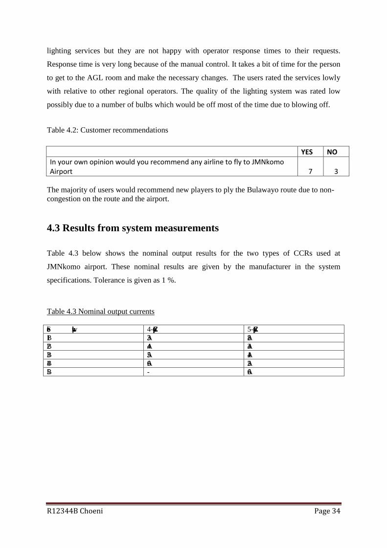
Table 4.2: Customer recommendations
YES NO
In your own opinion would you recommend any airline to fly to JMNkomo Airport 7 3
The majority of users would recommend new players to ply the Bulawayo route due to non-
congestion on the route and the airport.
4.3 Results from system measurements
Table 4.3 below shows the nominal output results for the two types of CCRs used at
JMNkomo airport. These nominal results are given by the manufacturer in the system
specifications. Tolerance is given as 1 %.
Table 4.3 Nominal output currents
Selector switch position 4-step CCR type 5-step CCR type B1 3.3 A 2.8 A B2 4.4 A 3.4 A B3 5.5 A 4.1 A B4 6.6 A 5.2 A B5 - 6.6 A

R12344B Choeni Page 35
Figure 4.2: Nominal output current for the 5-step type CCR
Figure 4.3: Nominal output currents for the 4-step type CCR
Table 4.4: Monthly average output currents measured on the 5-Step CCR for different
brilliances.
0
1
2
3
4
5
6
7
B1 B2 B3 B4 B5
Cu
rre
nt/
A
Selector switch position
Nominal currents 5-step type
0
1
2
3
4
5
6
7
B1 B2 B3 B4
Ou
tpu
t cu
rre
nt/
A
Selector switch position
Nominal currents - 4 step type

R12344B Choeni Page 36
Selector switch position
March average
April average
May average
June average
July average
Average for 5 months
B1 2.91 2.83 3.02 2.78 2.85 2.88
B2 3.45 3.30 3.43 3.46 3.40 3.41
B3 4.01 3.90 3.8 4.1 4.2 4.00
B4 5.02 5.25 5.20 5.22 5.15 5.17
B5 6.65 6.68 6.55 6.69 6.60 6.63
Figure 4.4: Average output currents for the 5-month period
From table 4.4 and figure 4.4, some of the measured output currents of the CCRs are
observed to be out of tolerance, that is, 1 % of the nominal values. These anomalies can be
attributed to old age of the equipment and also the faulty earth resistance of the lines feeding
the individual lights.
0
1
2
3
4
5
6
7
Marchaverage
April average May average June average July average Average for5 months
B1 2.91 2.83 3.02 2.78 2.85 2.88
B2 3.45 3.3 3.43 3.46 3.4 3.41
B3 4.01 3.9 3.8 4.1 4.2 4
B4 5.02 5.25 5.2 5.22 5.15 5.17
B5 6.65 6.68 6.55 6.69 6.6 6.63
Ou
tpu
t cu
rre
nt/
A
Measured currents
R12344B Choeni Page 37
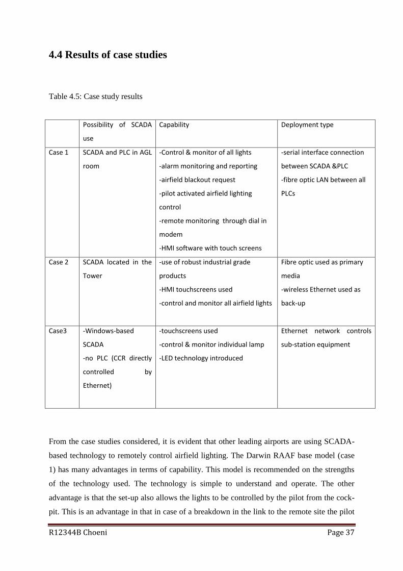
4.4 Results of case studies
Table 4.5: Case study results
Possibility of SCADA
use
Capability Deployment type
Case 1 SCADA and PLC in AGL
room
-Control & monitor of all lights
-alarm monitoring and reporting
-airfield blackout request
-pilot activated airfield lighting
control
-remote monitoring through dial in
modem
-HMI software with touch screens
-serial interface connection
between SCADA &PLC
-fibre optic LAN between all
PLCs
Case 2 SCADA located in the
Tower
-use of robust industrial grade
products
-HMI touchscreens used
-control and monitor all airfield lights
Fibre optic used as primary
media
-wireless Ethernet used as
back-up
Case3 -Windows-based
SCADA
-no PLC (CCR directly
controlled by
Ethernet)
-touchscreens used
-control & monitor individual lamp
-LED technology introduced
Ethernet network controls
sub-station equipment
From the case studies considered, it is evident that other leading airports are using SCADA-
based technology to remotely control airfield lighting. The Darwin RAAF base model (case
1) has many advantages in terms of capability. This model is recommended on the strengths
of the technology used. The technology is simple to understand and operate. The other
advantage is that the set-up also allows the lights to be controlled by the pilot from the cock-
pit. This is an advantage in that in case of a breakdown in the link to the remote site the pilot

R12344B Choeni Page 38
can go ahead and set his/her preferred settings without the assistance of the ground based air
traffic controller.
The system also uses serial link to the remote site which is not a very expensive way of
linking up two places which are not very far away from each other as is the case at JMNkomo
airport. This also allows the use of modems on each end which are relatively not expensive.
This model also enjoys the capability of remote location monitoring using a dial-in modem
which enables remote access to the SCADA system for easy fault diagnosis.
The disadvantage of this is the noise which might be induced on the twisted pair cables if
they run near places where high tension power cables are installed.

R12344B Choeni Page 39
CHAPTER 5
CONCLUSIONS AND RECOMMENDATIONS
5.1 Introduction
This chapter gives the conclusions on measurements and evaluation processes. A check
against the objectives of the research will be done to determine if they were met, and finally
recommendations to improve service delivery will be given. Proposals for future work in
related field of study will be given
5.2 Conclusions
The importance of improving safety of a modern day airport and compliance with ICAO
recommended practices cannot be overemphasised as evidenced by customer responses in
relation to the provision of airfield lighting services. This improvement can be achieved by
employing modern technology such as SCADA based system as used in other modern
airports shown by case studies.
Also from the technical documentation of the CCRs it was shown that the units are no longer
able to sustain stable outputs within the stated 1% tolerance. This means that even if the
SCADA based technology is employed we might still fail to meet expected customer quality
lighting system. Brilliance of the lights is dependent on the output current of the CCRs.
From the case studies presented there are many airports already employing the SCADA based
technology in their remote control of airfield lighting systems.

R12344B Choeni Page 40
5.3 Recommendations and suggestions
From the conclusions above it is recommended to acquire, install, commission and operate a
SCADA based remote control system modelled along the Darwin RAAF base for JMNkomo
airport for the benefit of the customers who fly into the airport especially at night. This will
not only enhance customer satisfaction and maintain customer loyalty and bring new business
for the airport but also improve on safety.
If feasible it is suggested that the SCADA based system for the remote control of airfield
lighting system at JMNkomo airport can be extended to include all the other radio frequency
based navigational aids used in the safe landing of aircraft. The inclusion of all air
navigations systems into the SCADA system will enable the air traffic controllers to have a
full view of the status of all navigation equipment at the click of a button. This will ensure
correct passage of information to aircraft during flight instead of the current situation where
the controller clears an aircraft to use a certain navigational aid only to be told by the pilot in
command that the system is not available.
Successful implementation of the SCADA based system at JMNkomo airport can be
extended to all airports without airfield lighting systems in place.

R12344B Choeni Page 41
References
[1] ICAO: Annex 14 (Aerodromes) to the Convention on International Civil Aviation, Vol.
1(Aerodrome Design and Operations) para. 5.3 and 8.3
[2] A. Daneels and W.Salter. “ What Is SACADA?”
International Conference on Accelerator and Large Experimental Physics Control Systems,
1999, Trieste, Italy
[3] A.Goel and R. S. Mishra. “Remote Data Acquisition Using Wireless-SCADA System”,
International Journal of Engineering (IJE), Vol. 3, Issue 1, 2009, p. 58-65.
[4] A. Daneels, W.Salter, what is SCADA? International Conference on
Accelerator and Large Experimental Physics Control Systems,
Trieste, Italy 1999.
[5] ADB-Tech-Corner-PC vs PLC.pdf. Available: www.adb_air.com
[6] Airport Lighting Control and Monitoring System, Programmable Logic Controller With
Centralized Control. Available: www.adb_air.com
[7] ADB Field Solutions. Available: www.adb_airfieldsolutions.com
[8] Aerodrome Design Manual part 5, para. 3.4 and 3.7
[9] www.rpctrading.com
[10] Anon, 2004, The Fundamentals of SCADA, Bentley Press, Incorporated, [Online].
Available: ftp://ftp2.bentley.com/dist/collateral/whitepaper/fundscada_whitepaper.pdf.
[11] Nieminen, Juha, 2009. Communication Bus Systems, Vaasa University of Applied
Sciences, Electrical Engineering, Lecture material.
[12] Data-Tech
Distributors.http://www.datatechdistributors.com/hitachi_cable_distributors.html
[13] Marihart, D.J., Communications Technology Guidelines for EMS/SCADA
Systems, Power Delivery, IEEE Transactions on, Volume: 16, Issue: 2, April 2001
Pages: 181–188
[14] Online: http://www.tutorialsweb.com/rf-measurements/coax-cables/coaxial-cable-

R12344B Choeni Page 42
construction.htm
[15] http://www.black-box.de/en-de/page/5459/fibre-optic-cable-construction
[16] www.airport-technology.com [17] www.adb-air.com [18] http:// www.cse.com.au [19] http://www.theafricanaviationtribune.com/ [20] T.Allett, 2009, The bright lights of Sydney: Australia's premier airport has completed a giant lighting upgrade. Airports International

R12344B Choeni Page 43
Appendix A
QUESTIONNAIRE: AIRFIELD LIGHTING
Interviewer: Humbulani Choeni
Section A: Formal data about the organisation
Q1: Name of the airline_______________________________________________________ Q2: Name and position of interviewed person______________________________________ Section B: Main Questionnaire
Q3: How long have you been flying to JMNkomo?__________________________________ Q4: Are you the captain/1st officer/2nd officer of this flight?___________________________ (Delete the inapplicable)
Q5: Approximately how many flying hours have you accrued ?_______________________ Q6: Are you a long-haul/short-haul pilot or both?___________________________________ Q7: On a scale of 1 to 5 how do you rate our service in terms of airfield lighting (1 being
Poor and 5 being
Excellent)________________________________________________________ Q8: Comments to expand on your choice in Q7 _______________________________________________________________________________________________________________________________________________________________________________________________________________________________________________________________________________________________________________________________________________________________________________________ Q9: How do you rate our services in relation to
(a) other service providers in the country____________________________________ (b) other service providers in the region_____________________________________
Q10: Given a choice would you recommend others to players to do business with us. YES/NO (delete inapplicable)
Any further comments pertaining to the above questions/answers_____________________________________________________________________________________________________________________________________________________________________________________________________________________________________________________________________________________________

R12344B Choeni Page 44
Appendix B
List of abbreviations
AGL Airfield Ground Lighting
ALCS Automatic Light Control System
ATC Air Traffic Control
CAAZ Civil Aviation Authority of Zimbabwe
CCR Constant Current Regulator
HIRL High Intensity Runway Lights
HMI Human Machine Interface
ICAO International Civil Aviation Organisation
I/O Input/Output
JMNkomo Joshua Mqabuko Nkomo
LAN Local Area Network
LIRL Low Intensity Runway Lights
MIRL Medium Intensity Runway Lights
MMI Man Machine Interface
PAPI Precision Approach Path Indicator
PLC Programmable Logic Controller
RTU Remote Terminal Unit
SARP Standard And Recommended Practices
WAN Wide Area Network

R12344B Choeni Page 45