micron scorpion z16040c - · pdf filecall attempt timer (anti jam): location 47 26 ... the...
TRANSCRIPT

SCORPION
Z16040C
FEATURES & OPERATION
MICRON SECURITY PRODUCTS LTD
April 2007
Abort Current Communication and Clear Reporting Queue (*59) 13

2
Abort Current Communications (*59) 10
Account Numbers: Locations 13-16 26
Add New User Code (*20) 10
Ademco 4+2 Reporting: Locations 236-281 27
Adjust Battery Charging Voltage (*07) 13
Alarm on Opening 14
Alternate Entry Delay: Locations 613-616 29
Alternate Entry Zones 15
Answer after XX Rings: Location 48 27
Areas to Report: Locations 56-61 27
Arm all Areas (9#) 9
Arm and Disarm all Areas or Disarm Selected Areas 28
Arming and Disarming the Panel 14
Assign Outputs to Areas: Locations 521-525 29
Assign User Code to Areas: Locations 400-447 28
Assign Zones to Areas: Locations 451-466 28
Assigning Zones to Areas 15
Auto Arm and Auto Disarm Zones by Area(s) 14
Auto Arm and Auto Disarm: Location 651 30
Auto Arm if No Activity: Location 652 30
Auto Arm Time (*51) 10
Auto Arm Time with No Activity: Location 653 30
Auto Arm Zones by Area with no Activity 14
Auto Bypass Zones 15
Auto Disarm Time (*52) 10
Call Attempt Timer (Anti Jam): Location 47 26
Call Attempts: Locations 40-45 26
Change User Code (*21) 10
Chime Mode (*71 to *74) 11
Circuit Board Layout and Wiring Diagram 5
Clone Pre-programmed Data from Prom Socket to Panel (*08) 13
Clone to Prom Socket from Pre-programmed Panel (*09) 13
Closed Loop Zones 14
Common Entry Zones 15
Communication Option: Location 65 27
Communication Programming 25
Communication Progress Tracker (Initiates Call to CMS) (*03) 13
Connection to Mains Earth 33
Cross Zone Timer: Location 623 29
Cross Zones (Double Knock) 15
Cross Zones (Double Knock): Location 622 29
Current Rating 33
Custom Keypad Keys 14
Custom Keys: Locations 624-628 29
Delayed Night Zones (Stay Zones) (*91 to *94) 12
Delete User Code (*23) 10
Dialling Cycles: Location 46 26
Dialling Mode: Location 49 27
Disable Double End of Line Tampers: Location 661 31
Double End of Line Zones 14
Emergency Access to Program Mode: Location 661 28
Enter or Change Panel Clock Time (*05) 13
Enter or Change Panel Clock Time (*50) 10
Entering Data 25
Entering Hexadecimal Characters 30
Entering Program Mode from the Keypad 25
Entry / Exit and Pre-Alert Entry Zones 15
Entry Delay Time: Locations 609-612 29
EOL Resistors 33
Erasing a Memory Location 25
Event Reporting Codes (Contact ID): Locations 200-229 27
Example of Home Dialling 25
Exit Delay Time: Locations 605-608 29
Fax / Answer Phone Defeat: Location 22 26
Fire Panic (1 + 3) 12
Follow Me Telephone Numbers (call diversion) (*31 or *32) 10
Force Arming: Location 654 30
Force Panel to Answer Call (*00) 13

3
Hours Between Test Calls: Location 63 27
Icon LCD Keypad 31
Installer Access Programming Code: Location 300 28
Installer Keypad Commands 12
Installer Programming Access Code (XXXX) (Default 0000) 12
Installer Walk Test Mode (*85) 11
Instant Night Zones (Stay Zones) (*96 to *99) 12
Key Switch Zones 14
Keypad and Telephone Entry Commands 8
Line Test Mode: Location 67 27
Local Programming 28
Manual Bypass of Zones when Arming (*11) 10
Medical Panic (4 + 6) 12
Miscellaneous Options: Location 661 30
Miscellaneous Status Recall (*83) 11
Night Arm Entry Delay (Stay Mode): Locations 617-620 29
Non ‘Alarm’ Reports: Locations 17-18 26
Other Panel Functions 14
Output Events: Locations 556-582 29
Output Options: Locations 536-540 29
Output Timers: Locations 526-530 29
Pager Calling 26
Pager End Character: Location 21 26
Pager Space Character: Location 20 26
Pager Start Character: Location 19 26
Panel Dials and Calls Microcom Computer (Toll Saver) (*01) 13
Product Features 7
Product Overview 4
Programming Explanations 25
Programming Locations and Memory Map 16
Quick Arm 9
Reading Programmed Data from the Keypad. 31
Remote Arming From a DTMF Telephone (*1) 9
Remote Disarming from a DTMF Telephone (*3) 9
Remote Operation to Turn Off Output 4 from a DTMF Telephone (*7) 9
Remote Operation to Turn On Output 4 from a DTMF Telephone (*5) 9
Reset Panel to factory Defaults (*10) 13
Select Dialling Format: Locations 7-12 26
Sending Duress after Disarming 14
Sending Test Signals 11
Sequential Entry Zones 15
Sixteen Zone LED Keypad 32
Smoke Detector Reset (*77) 11
Smoke Detector Zones 15
Swinger Shut Down Zones 15
Swinger Shutdown: Location 621 29
System Walk Test (*85) 13
Technical Specifications 33
Telecom Waiver 34
Telephone Numbers: Locations 1-6 25
Temporary User Code (valid until midnight) (*24) 10
Test Signal: Location 62 27
The Keypads 31
Two Key Panic (*+ #) 12
Upload / Download Password: Location 66 27
User Code Options: Locations 349-396 28
User Codes 14
User Codes: Locations 301-348 28
User Initiated Call Diversion (follow me) Number Test (*38 or *39) 10
User Keypad and Telephone Entry Commands 9
Zone Alarm History Recall (*80) 11
Zone Disable 15
Zone Filters: Locations 499-514 29
Zone Input Sensitivity (Filters) 15
Zone Options: Locations 467-498 28
Zone Tamper Alarm Recall (*81) 11
Zone Wiring Configurations 6

4
Product Overview
The Scorpion Z16040C is a fully programmable sixteen zone, four partition control communicator.
The sixteen zone inputs actively scan both zone and tamper detection with double end of line resistors. The zones may be
programmed as instant, delayed, twenty four hour, fire, medical, home and away, chime, key switch and zone shutdown
after a specified number of activations.
The Z16040C is scanning all inputs continuously and can be programmed by zone to capture any valid activation from
10mS to 1.28 seconds.
Up to four sixteen zone icon LCD or LED keypads and Nitewatch stations may be configured to the control panel.
The forty eight user codes can be individually programmed to action up to twelve different commands. The LCD and
LED keypads have three custom keys that may be programmed for single action fast user response for fire, medical or
panic conditions.
This user friendly panel offers many features including:
Automatic arm/disarm and auto arm if no activity in any of the selected areas.
Wireless capabilities, for remote arm/disarm, garage door operation, outside lighting control and full panic alert from a
key ring transmitter. (RCM receiver option)
Four programmable switching outputs and one high current siren output to activate any of thirty eight different conditions.
Communication is programmable to call up to six telephone numbers and report to a central monitoring station in formats
including Contact ID, 4+2 DTMF, 4+2 pulse 20pps and 4+2 pulse 10pps.
The alarm panel may also be programmed to call a private telephone or mobile phone (home dial), alerting the user to an
alarm and informing the zone(s) that have been activated, or call a numeric pager with full visual description of the
reported event.
In home dial mode the user can redirect the alarm call to an alternate telephone (follow me) number by entering a simple
keypad command.
The Scorpion Z16040C can be programmed:
Locally at the keypad
With a pre-programmed ‘clone’ chip
Remotely using micron’s Microcom II upload/download software

5
Circuit Board Layout and Wiring Diagram
IN
OUT
Zone 15
Zone 13
Zone 9
Zone 14
Zone 10
Zone 12
Zone 8
Zone 7
Zone 6
Zone 5
Zone 4
Zone 3
Zone 2
Zone 1
Telco
Zone 16
Common
Common
Common
Common
Common
Common
Common
Common
CloneSocket
Pin 1
+-Accessory Power C
lock
D
ata
Sir
en
+
-
Sir
en
-
Ou
t 1
Ou
t 2
Ou
t 3
Ou
t 4
AC
AC
Zone 11
+
+
+
+
+
+
+
+
+
+
-
-
-
ToAccessory
Power
-
-
-
-
-
-
Led
Accessory
Power Bus+Ve -Ve
Tamper
Zone
4k.7
4k.7
.4k.7 Tamper4k.7Zone
. ...
. .
.
.
N/C
N/C
N/CN/O
N/O
micron
LCD
ARM
EM ERGENCY
UNSAFE ARMED
m icron
Nit eWatc h
NiteWatch
-
TelecomLine IN
Common
Tamper
Zone
4k.7
4k.7N/C
N/C
N/O
The zones are scanning a 4k.7 balanced loop to common.
The tamper is a 24 hour active circuit to common and iswired in series with a 4k.7 resistor. The zone has a
4k.7 resistor and is wired in parallel.
For devices that have no tamper like magnetic reed
contacts, panic and f ire actuators etc.. connect as above.
4k.7
4k.7N/CZoneN/O
Common
Zone 1
Zone wiring with tamper
Zone wiring without tamper
When installing a smoke detector connect the 4k.7resistor across the N/O contacts.*
*
3 AMP
Mains Supply
N E P
Earth
Zone 1
Wire
Fuse2 Amp
Battery
3 AMP
Siren +ve Output
Detect ion
Devi ces
Audible / Visual Devices
Maximum load 1.5 Amps
Maximum Four Keypads
V
Max Load: 250mA
Outputs switching to -Ve
Piezo
Strobe
micron
Detect ion
+Ve -Ve
RED
BLACK
YELLOW
BLUE
RED
BLACK
Telephone
From Exchange
RED
BLA
CK
The siren +Ve is connected via a 3 Amp fuse to the + Ve side
of the panel's standby battery. For devices that draw high
current when in alarm, audible / visual warning indicatorsetc.. it is recommended that this +Ve supply is used.
*

6
Zone Wiring Configurations
TamperZone
4k.7
Zone
Common
Zone
Common
Zone
4k.7
4k.7
Zone with
Zone with no tamper
*
* Connecting to a zone with no tamper
W hen Installing open circuit devices,
such as smoke detectors etc
connect
the 4k.7 resistor across the N/O
contacts (24 hour)
24 hour active tamper
Relay +Ve -Ve
Zone Common +Ve -Ve
W iring a PIR with the
tamper connected
N/O
N/O
4k.7
Tamper
4k.7
The TAMPER is a 24 hour active
circuit and is wired in series with a
4k.7 resistor
The ZONE has a 4k.7 resistor and is
wired in parallel
W iring a PIR without
a tamper connected
+Ve -VeTamperRelay
Zone Common +Ve -Ve
4k.7 4k.7
4k.7
Note: Double end of line tampers can be disabled for all zones and single 4k.7 resistor alarm
zones established at Location 661, LED 5 turned on.

7
Product Features
01. Sixteen zone control communicator.
a) Zone inputs actively scan both zone and tamper with double end of line resistors.
b) Zones may be selected to capture any valid activation from 10mS to 1.28 seconds.
c) Zone alarm history recall, (128 levels of memory).
d) Zones maybe programmed as:
Instant
Entry
Alternate entry
Sequential entry
Twenty four hour
Fire / smoke
Medical
Home or away
Chime
Key switch
Zone shutdown after xx activations
Common zones
Loop zones (no balanced line)
Zone disable
Cross zones / double knock
Zone input sensitivity (filters)
02. Four partitions.
03. Up to four sixteen zone icon LCD, LED keypads / night stations with full digital and graphic display.
04. Forty eight user codes from two to eight digits in length with twelve command types.
05. Three keypad custom keys for single action fast user response.
06. Quick arm commands for all four areas.
07. One key arm all or arm all disarmed areas.
08. Smoke detector reset command.
09. Two key panic, fire and medical emergency key combinations.
10. Disarm under duress key command.
11. Temporary user codes automatically disabled at midnight.
12. Remote arm / disarm and output control from a DTMF telephone.
13. Programmable ‘lock out’ for one minute if six invalid user codes are entered.
14. Auto arm / auto disarm (times selected by user).
15. Auto arm when no activity from selected areas.
16. Remote arm / disarm, panic, garage door and lighting control from a wireless receiver (option).
17. Five programmable outputs:
a) Siren Output ........................................... Max: 1.5 Amps non inductive load
b) Aux: Output 1 ........................................ Max: 250 mA sink output
c) Aux: Output 2 ........................................ Max: 250 mA sink output
d) Aux: Output 3 ........................................ Max: 250 mA sink output
e) Aux: Output 4 ........................................ Max: 250 mA sink output
Thirty eight events / options can be assigned to the outputs.
18 Keypad adjustment of battery charging voltage.
19 Dynamic battery test
Communicator
20 Six telephone numbers with up to twenty digits per number.
21 Transmits in all current formats to a central monitoring station (CMS).
22 Transmits to a user’s telephone or mobile phone and sends a ‘siren warble’ and zone identifier (home dial).
23 Transmits to a numeric pager and sends full visual description of the reported event.
24 Four customer account numbers.
25 Non alarm reports may be programmed to a secondary number.
26 Dialling mode: a) DTMF
b) Pulse dial (decadic)
c) Reverse dial (decadic)
27 Test signal DD:HH:MM
28 Line fault monitoring.
29 Communication progress tracker (keypad display).
30 Opening report after an alarm, when user open/close reporting to a CMS not programmed.
31 Alarm follow me command when programmed for home dial (call diversion).
32 Answer after xx rings (answer phone / fax defeat).
33 Microcom II upload / download programmable.
34 Full history log of events, time and date stamped.

8
Keypad and Telephone Entry Commands
Keypad Entry Command
1# Quick arm area A
2# Quick arm area B
3# Quick arm area C
4# Quick arm area D
Call the alarm
phone number
from a touch
tone phone and
enter…..
*1 <master user code> # Area armed using a touch tone phone. For areas A-D.
*3 <master user code> # Area disarmed using a touch tone phone. For areas A-D.
*5 <master user code> # Output turned on using a touch tone phone.
*7 <master user code> # Output turned off using a touch tone phone.
9# Arm all areas or arm all areas not already armed
*11 <enabled user code> * <zone to exclude> # Manual bypass of a zone.
*20 <master user code> # <new user code> # Add a new user code.
*21 <master user code> # <old user code> # <new user code> # Change a user code.
*23 <master user code> # <user code to delete> # Delete a user code.
*24 <master user code> # <temporary user code> # Valid until midnight of the same day.
*31 <master user code> # <follow me telephone number 1> # Alarm calls this number when alarm activated.
*32 <master user code> # <follow me telephone number 2> # Alarm calls this number when alarm activated.
*38 <master user code> # Alarm calls this number to test telephone number 1.
*39 <master user code> # Alarm calls this number to test telephone number 2.
*50 <master user code> # <enter or change alarm clock time HHMM> # 24 hour format.
*51 <master user code> # <auto arm time HHMM> # 24 hour format.
*52 <master user code> # <auto disarm time HHMM> # 24 hour format.
*59 <master user code> # To abort current communications.
*62 <master user code> # <enter time to send test signal HHMM> # Sets test signal time in 24 hour format
*71 Chime area A On/Off
*72 Chime area B On/Off
*73 Chime area C On/Off
*74 Chime area D On/Off
*77 Smoke alarm reset
*80 Zone alarm history recall. Step through history with the # key. Press any key to leave program.
*81 Tamper alarm recall
*83 Miscellaneous status recall (see alarm status recall menu on page 11)
*85 Walk test detector mode. Siren sounds once to verify an alarm activation.
*91 Nite arm/disarm area A
*92 Nite arm/disarm area B
*93 Nite arm/disarm area C
*94 Nite arm/disarm area D
*96 Instant Nite arm area A (In Instant mode you can only disarm using a valid user code)
*97 Instant Nite arm area B (In Instant mode you can only disarm using a valid user code)
*98 Instant Nite arm area C (In Instant mode you can only disarm using a valid user code)
*99 Instant Nite arm area D (In Instant mode you can only disarm using a valid user code)
* + # Two key panic. Press both keys simultaneously.
1 + 3 Fire panic. Press both keys simultaneously.
4 + 6 Medical panic. Press both keys simultaneously.
0000 0000 # Enters panel program mode

9
User Keypad and Telephone Entry Commands
If the system is partitioned into areas, keypad commands with master user code operations can only be entered on a
keypad assigned to the partitioned area. Assign a keypad to an area partition by assigning the four switches on the
back of the sixteen zone LCD or LED keypad.
Switch 1: area ‘A’
Switch 2: area ‘B’
Switch 3: area ‘C’
Switch 4: area ‘D’
(Visual and audible enunciation is only displayed on keypad(s) assigned to specific partitioned areas).
Quick Arm
Arm selected programmed areas.
Enter 1 # for area ‘A’
2 # for area ‘B’
3 # for area ‘C’
4 # for area ‘D’
Remote Arming From a DTMF Telephone (*1)
Dial the panel telephone number and wait for two rings, hang up the telephone and call back within 60 seconds.
The panel will automatically answer on the first ring with a high low tone acknowledgement. Location 22 must be
programmed with a 1 (fax and answer phone defeat) for this function to operate.
Enter *1 then a <master user code> # for the area to arm. Locations 349 to 396, (user options) LED 3 must be
turned on for each authorised user code to enable this command. A 6 beep confirmation will be heard if a valid
user code to arm that area is entered. A long beep will be heard if the area is already armed.
Remote Disarming from a DTMF Telephone (*3)
Dial the panel telephone number and wait for two rings, hang up the telephone and call back within 60 seconds.
The panel will automatically answer on the first ring with a high low tone acknowledgement. Location 22 must be
programmed with a 1 (fax and answer phone defeat) for this function to operate.
Enter *3 then a <master user code> # for the area to disarm. Location 349 to 396, (user options) LED 3 must be
turned on for each authorised user code for this command to operate. A 3 beep confirmation will be heard if a
valid user code to disarm that area is entered. A long beep will be heard if the area is already disarmed.
Remote Operation to Turn On Output 4 from a DTMF Telephone (*5)
Dial the panel telephone number and wait for two rings, hang up the telephone and call back within 60 seconds.
The panel will automatically answer on the first ring with a high low tone acknowledgement. Location 22 must be
programmed with a 1 (fax and answer phone defeat) for this function to operate.
Enter *5 then a <master user code> # for output 4 to turn on. Location 349 to 396, (user options) LED 2 must be
turned on for each authorised user code to enable this command. If the output is already turned on, a long reject
beep will be heard.
Remote Operation to Turn Off Output 4 from a DTMF Telephone (*7)
Dial the panel telephone number and wait for two rings, hang up the telephone and call back within 60 seconds.
The panel will automatically answer on the first ring with a high low tone acknowledgement. Location 22 must be
programmed with a 1 (fax and answer phone defeat) for this to function to operate.
Enter *7 then a <master user code> # for output 4 to turn off. Locations 349 to 396, (user options) LED 2 must
be turned on for each authorised user code to enable this command. If the output is already turned off, a long reject
beep will be heard.
Arm all Areas (9#)
Entering 9# will arm all areas or arm all areas not already armed. Disable this function at Location 661, LED 8 on.

10
Manual Bypass of Zones when Arming (*11)
Enter *11 then a <master user code> *, all zones 1 to 16 will be displayed. Select the zone to be bypassed by
pressing the corresponding key on the keypad then #. The selected zone indicator will now be flashing, confirming
the selected zone has been bypassed. Repeat this procedure for further zones followed by #. To arm the system,
press the # key. Locations 483 to 498, (zone options) LED 5 must be turned on to enable this command.
Add New User Code (*20)
Enter *20 then <master user code> # then <new user code> #
Change User Code (*21)
Enter *21 then <master user code> # then <old user code> # then <new user code> #
Delete User Code (*23)
Enter *23 then <master user code> # then <user code to delete> #
Temporary User Code (valid until midnight) (*24)
Enter *24 then <master user code> # then <temporary user code> #
Follow Me Telephone Numbers (call diversion) (*31 or *32)
This function allows the user to program two temporary telephone numbers and diverts alarm calls to that number.
Enter *31 then <master user code> # then <follow me telephone number 1> #
Enter *32 then <master user code> # then <follow me telephone number 2> #
User Initiated Call Diversion (follow me) Number Test (*38 or *39)
This function allows the user to test the ‘follow me’ number, which sounds a Hi Lo tone for call confirmation.
Enter *38 then <master user code> # Initiates test call to telephone number 1
Enter *39 then <master user code> # Initiates test call to telephone number 2
Enter or Change Panel Clock Time (*50)
Enter *50 then <master user code> # then <current clock time HHMM> # (24 hour format).
Auto Arm Time (*51)
Enter *51 then <master user code> # then <auto arm time HHMM> # (24 hour format)
Select areas to auto arm/disarm at Location 651. If an auto arm pre-alert is selected, the keypad will generate an
audible alert 5 minutes before the panel auto arms. Pressing any key on a keypad assigned to that area during the pre-
alert time will cancel auto arming for that 24 hour period. The pre-alert starts at the programmed auto arm time.
If auto arming is programmed for multiple areas, then the time between the auto arming times of those areas must
not be less than 10 minutes apart. The auto arming time can only be activated by an authorised user code and
keypad assigned to the area in which auto arming is to operate.
Auto Disarm Time (*52)
Enter *52 then <master user code> # then <auto disarm time HHMM> # (24 hour format)
If the 5 minute pre-alert is selected, the panel will auto disarm 5 minutes after the programmed auto disarm time. The
auto disarming time can only be activated by an authorised user code and keypad assigned to the area in which auto
arming is to operate.
Abort Current Communications (*59)
Enter *59 then <master user code> #
Aborts communications currently in progress and clears all outstanding events from the reporting buffer. Events
deleted from the buffer are still retained in the event history file.

11
Sending Test Signals
Enter the *62 command then <master user code> # then <test signal time HHMM> # to set the panel’s test signal
time. Enter HHMM in 24 hour format eg 1830 = 6:30pm. See Locations 62, the test signal time, and Location
63, hours between test calls.
Chime Mode (*71 to*74)
Enter *71 to*74 to turn on/off chime mode for selected areas ‘A’ to ‘D’
Enter *71 area ‘A’
Enter *72 area ‘B’
Enter *73 area ‘C’
Enter *74 area ‘D’
Turning on an area chime zone command will generate a series of fast beeps for 3 seconds. Turning off chime mode
will generate a two beep acknowledgement. When a chime zone is activated the keypad will emit a series of beeps.
After the initial chime alert, chime mode sleeps while activity is present. When the panel senses no activity, it will
count down 30 seconds and again sound an audible alert if further activity is detected in the chime zone.
Chime zones are selected at Locations 467 to 482, LED 4 on.
Chime mode is only active when the panel is disarmed.
Smoke Detector Reset (*77)
Entering the *77 command will momentarily activate the assigned output and reset a latched smoke detector alarm.
Program Locations 536 to 540, LED 7 on.
A 12 second ‘sleep period’ is initiated after a smoke detector reset command to allow a smoke detector(s) to stabilize.
Zone Alarm History Recall (*80)
Entering *80 recalls the last zone alarm event. Up to 128 activations may be recalled by pressing the # key.
The panel steps back 1 event each time the # key is pressed. Alarmed zones are displayed as flashing zone
LED’s. Press any key except # to exit program.
Zone Tamper Alarm Recall (*81)
Entering *81 recalls the last zone tamper alarm.
Miscellaneous Status Recall (*83)
Entering *83 recalls miscellaneous panel alarms. (See below for LED indication).
LED MISCELLANEOUS ALARM CONDITIONS LED 1 Panic alarm
LED 2 Battery is discharged or faulty
LED 3 AC mains power to the panel has failed
LED 4 A dialler communication has failed
LED 5 Phone line is faulty or disconnected
LED 6 Auxiliary 12V power supply overloaded
LED 7 Siren output fault. Circuit open or overloaded
LED 8 Duress initiated from keypad
Installer Walk Test Mode (*85)
Entering *85 sets the panel to installer walk test mode without arming the system. The siren sounds once when a
detection device is activated. Press any key to exit.

12
Delayed Night Zones (Stay Zones) (*91 to *94)
Enter *91 to *94 to select night zones to arm by area. When night arming the keypad will sound a three beep
acknowledgement and the panel will begin a silent arming cycle.
Enter *91 area ‘A’
Enter *92 area ‘B’
Enter *93 area ‘C’
Enter *94 area ‘D’
After the pre-programmed exit delay, Locations 605 to 608, the panel will night arm and give a two beep
confirmation that the night zones are armed. If a night arm zone is in alarm, the keypad will emit an audible tone
and the alarmed zone will flash. When the arming delay time has expired, the alarmed zone will auto isolate and
remain in that condition until the panel is disarmed and re-armed. Select night zones at Locations 483 to 498, LED
2 on. Night zone entry delay times are selected at Locations 617 to 620. When night armed the alarm can only be
disarmed using a valid user code.
Instant Night Zones (Stay Zones) (*96 to *99)
Enter *96 to *99 to select instant night zones to arm by area. Zones will arm instantly and will activate on entry
with no delay. If a zone is alarmed when arming, the panel will give no visual or audible indication and the zone
will auto isolate. Select night zones at Location 483 to 498, LED 2 on. When night armed the alarm can only be
disarmed using a valid user code.
Two Key Panic (* + #)
Pressing keys * + # together will generate a full panic alarm. Select the output at Location 562.
Fire Panic (1 + 3)
Pressing keys 1 + 3 together will generate a full fire panic alarm. Select the output at Location 563.
Medical Panic (4 + 6)
Pressing keys 4 + 6 together will generate a full medical panic alarm. Select the output at Location 564.
Installer Programming Access Code (XXXX) (Default 0000)
Enter 0000 then # to access program mode, to exit program mode press **. Change the installer program code at
Location 300. The installer code can be from 2 to 8 digits in length.
Installer Keypad Commands
Commands notated < > indicate a numeric code to be entered on the keypad to execute that function.
Keypad entry Command
*00 Force panel to answer call
*01 <nnnnnn> # Panel dials telephone number nnnnnn
*03 <installer code> # Communication progress tracker (installer initiated test call to CMS)
*05 <installer code> # Enter or change the panel clock time
*07 <installer code> # Adjust battery charging voltage
1 = Increase voltage
2 = Decrease voltage
# = Save voltage setting
* = Abort setting
*08 <installer code> # Clone from prom socket to panel (24C32 chip)
*09 <installer code> # Clone to prom socket from panel (24C32 chip)
*10 (3) (1) (*) (#) Resets panel to factory defaults. (Location 661, LED 4 must be Off)
*59 <master user code> # Abort current communications
*85 Panel enters walk test mode and the siren sounds once for each detector activation
13
Force Panel to Answer Call (*00)
The panel may be forced to answer by entering *00. This command forces the panel to immediately answer an
incoming call. This function is typically used when an on site installer force answers the panel for a call initiated by
micron’s Microcom II upload/download program.
Panel Dials and Calls Microcom Computer (Toll Saver) (*01)
Enter *01 then <nnnnnnn> # the phone number for the Microcom computer. After the # is entered, the panel will
give an acceptance beep-beep and dial the number, then wait for the Microcom computer’s modem tone. If the
connection is not successful, the panel disconnects from the line. If the number dialled is busy a long reject beep
will be heard. Retry later.
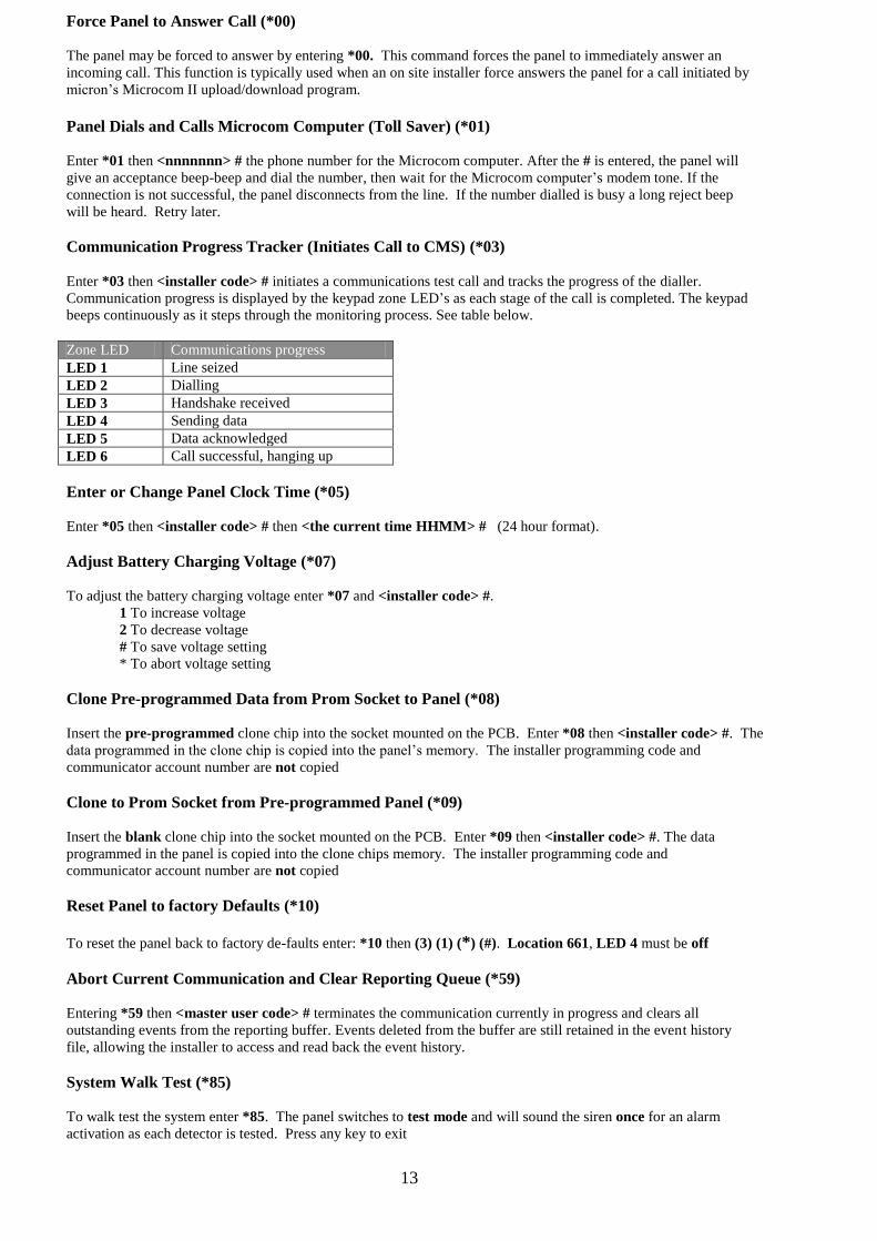
Communication Progress Tracker (Initiates Call to CMS) (*03)
Enter *03 then <installer code> # initiates a communications test call and tracks the progress of the dialler.
Communication progress is displayed by the keypad zone LED’s as each stage of the call is completed. The keypad
beeps continuously as it steps through the monitoring process. See table below.
Zone LED Communications progress
LED 1 Line seized
LED 2 Dialling
LED 3 Handshake received
LED 4 Sending data
LED 5 Data acknowledged
LED 6 Call successful, hanging up
Enter or Change Panel Clock Time (*05)
Enter *05 then <installer code> # then <the current time HHMM> # (24 hour format).
Adjust Battery Charging Voltage (*07)
To adjust the battery charging voltage enter *07 and <installer code> #.
1 To increase voltage
2 To decrease voltage
# To save voltage setting
* To abort voltage setting
Clone Pre-programmed Data from Prom Socket to Panel (*08)
Insert the pre-programmed clone chip into the socket mounted on the PCB. Enter *08 then <installer code> #. The
data programmed in the clone chip is copied into the panel’s memory. The installer programming code and
communicator account number are not copied
Clone to Prom Socket from Pre-programmed Panel (*09)
Insert the blank clone chip into the socket mounted on the PCB. Enter *09 then <installer code> #. The data
programmed in the panel is copied into the clone chips memory. The installer programming code and
communicator account number are not copied
Reset Panel to factory Defaults (*10)
To reset the panel back to factory de-faults enter: *10 then (3) (1) (*) (#). Location 661, LED 4 must be off
Abort Current Communication and Clear Reporting Queue (*59)
Entering *59 then <master user code> # terminates the communication currently in progress and clears all
outstanding events from the reporting buffer. Events deleted from the buffer are still retained in the event history
file, allowing the installer to access and read back the event history.
System Walk Test (*85)
To walk test the system enter *85. The panel switches to test mode and will sound the siren once for an alarm
activation as each detector is tested. Press any key to exit

14
Other Panel Functions
This section provides more detailed descriptions of the Scorpion Z16040C features and functions. A brief
explanation of functionality is given for each memory location in the section headed Programming Locations.
User Codes
Each of the 48 user codes can be assigned to any of the 4 areas at Locations 400 to 447. Each code can be from
two to eight digits in length and programmed to execute up to twelve commands. If no options are selected for a
user code, that code will be assigned to area ‘A’ and will perform only a basic arm/disarm function. See Locations
349 to 396 for user code options. User code 48 can be reserved as a temporary code that is deleted at midnight.
Custom keypad Keys
There are three ‘custom keys’ (F1) (F2) (F3) on the icon LCD and sixteen zone LED keypads. These keys can be
programmed with up to eight commands, for fast single key response. See Location 624 to 628 for custom key
options. To operate ‘custom keys’ press and hold the key until a second beep is heard then release.
Arming and Disarming the Panel
Enter a valid <enabled user code> followed by the # key.
Sending Duress after Disarming
To generate a duress alarm while disarming, enter a valid <enabled user code> then press and hold the # key until
a second beep is heard (approx 1 second) then release. If monitored, an opening followed by a duress code will be
reported to the central monitoring station (CMS).
Alarm on Opening
If the panel has been programmed not to report by user to a CMS but a report by user is required after an alarm on
opening, select this option at Location 65, LED 7 on (global to all areas).
Auto Arm and Auto Disarm Zones by Area(s)
Programming zones in areas to auto arm and auto disarm, Location 651 (area select), is a controlled function and
can be initiated by the user with the *51 and *52 commands. A 5 minute pre-alert prior to arming is available using
Location 651, LED 8 on. To cancel auto arming during the 5 minute pre-alert, press any key on the assigned area’s
keypad. Cancelling the auto arm will reset the timer to auto arm at the programmed time the next day.
Auto Arm Zones by Area with no Activity
Auto arm with no activity is a programmable function at Location 652 (area select). Location 653 sets the no
activity countdown time. If selected, the detection devices within the areas will monitor movement (activity) and
after the pre-programmed ‘no activity time’, auto arm the system. A 5 minute pre-alert prior to arming is available
using Location 652, LED 8 on. To cancel auto arming with no activity during the 5 minute pre-alert, press any key
on the assigned area’s keypad or walk into the assigned area and activate a zone. Cancelling the auto arm with no
activity will reset the timer and the ‘no activity’ count down time will restart.
Double End of Line Zones
All 16 zones are balanced with two 4k.7 end of line resistors (zone and tamper). After an alarm event, the installer
or user can enter a keypad command to re-call the alarm history and determine if the detector or the tamper caused
the alarm event. Individual outputs can be assigned for the detector and tamper at Locations 556 and 558. Note
that the tamper is a 24-hour circuit and is active in both the armed and disarmed state.
Closed Loop zones
Zones can be programmed as ‘closed loop zones’ at Locations 467 to 482, LED 7 on. Zones in this mode do not
require a 4k.7 resistor and are not tampered. Closed loop zones are normally used when installing door contacts etc.
Key Switch Zones
Zones programmed as key switch zones at Locations 467 to 482, LED 3 on, can be assigned to arm and disarm
selected areas by a momentary key switch or an access control reader.

15
Entry / Exit and Pre-Alert Entry Zones
Entry / exit delay zones can be programmed at Locations 467 to 482, LED 2 and 6 on. Entry delay times are set at
Locations 609-612 and exit delay times at Locations 605-608 with delays from 10 to 100 seconds.
Alternate Entry Zones
Zones maybe selected as an alternate entry path at Locations 467 to 482, LED 2 and 5 on. Alternate entry zones
are zones that allow the user to gain access through a second area where a longer entry delay is required to disarm
the alarm. Entry delay times are set at Locations 613-616 with delays up to 100 seconds.
Sequential Entry Zones
Zones programmed as sequential entry at Locations 483 to 498, LED 6 on, behave as normal entry zones if the
correct entry path is taken. Any sequential entry (follower) zones activated outside the programmed sequence will
activate the alarm instantly. This feature should be installed and programmed in consultation with the customer.
Common Entry Zones
Common entry zones to areas are programmed at Locations 451 to 466. Up to four areas can be accessed through
one common entry point. When common entry zones are assigned, the first user to disarm their area would also
disarm the common entry zone. The common entry zone will remain disarmed until the last area arms.
Smoke Detector Zones
Smoke zones are programmed at Locations 483 to 498. With LED 4 on smoke zones are active in armed mode
only. With LED 3 and 4 on smoke zones are 24 hour zones and are active in armed and disarmed mode. When a
smoke detector activates, the installer can program an output to give a 4 second reset pulse on the first activation at
Locations 536 to 540, LED 7 on (4 second reset). The panel will then wait for 20 seconds and check the smoke
detector status. If the smoke detector is still in alarm after this period, an alarm is generated. A smoke alarm report
will also be sent to the CMS if the system is monitored. See Location 557 for smoke output event.
Swinger Shut Down Zones
The swinger shut down count may be set from 1 to 7 activations before a zone is disabled and is programmable at
Location 621. When the programmed number of activations has occurred within any one arming cycle, the zone
is disabled and can not generate further alarms until the panel is disarmed and re-armed. This applies to all zones
including zones programmed as night or 24 hour zones.
Cross Zones (Double Knock)
Cross zones are selected at Locations 483 to 498, LED 7 on. The zones can be configured for two activations on
the same zone, different zones or same or different zones at Location 622. The cross zone timer is set at
Location 623. If two activations occur on either or any zone within the programmed time frame an alarm condition
will be generated. If there is not a second activation within the programmed time, the zone will re-set and await the
next activation count. For security reasons it is important to carefully consider the layout of the security system
when programming cross zones.
Auto Bypass Zones
Zones to auto bypass after the exit delay are programmed at Locations 483 to 498, LED 8 on (zone select).
Zone Input Sensitivity (Filters)
The panel continuously scans all inputs and can be programmed by zone at Locations 499 to 514 to capture any
valid activation from 10mS to 1.28 seconds.
Assigning Zones to Areas
Zones can be assigned to any of the 4 partitioned areas available at Locations 451 to 466. Each of the four areas
can be assigned an output for that area at Locations 521 to 525.
Zone Disable
Spare zones can be disabled at Locations 467 to 482, LED 8 on. When zones are disabled there is no need to fit a
4.7k resistor across the zone input.

16
Programming Locations and Memory Map
50..55 Reserved
56 Areas 1 to 4 Areas report to telephone 1 LED 1: on: area A 1, 2, 3, 4
57 Areas 1 to 4 Areas report to telephone 2 LED 2: on: area B 1, 2, 3, 4
58 Areas 1 to 4 Areas report to telephone 3 LED 3: on: area C
59 Areas 1 to 4 Areas report to telephone 4 LED 4: on: area D
60 Areas 1 to 4 Areas report to telephone 5
61 Areas 1 to 4 Areas report to telephone 6 Note that the # key must be pressed
after you have completed an LED
toggle selection.
Location Contents and field size Detail Remarks Defaults
1 Phone number 20 digits Telephone number 1 Can be a normal or an end user
(follow me) number
2 Phone number 20 digits Telephone number 2 Can be a normal or an end user
(follow me) number
3 Phone number 20 digits Telephone number 3
4 Phone number 20 digits Telephone number 4
5 Phone number 20 digits Telephone number 5
6 Phone number 20 digits Telephone number 6
7 Number 0-9
Telephone number 1 format 0 = Contact-ID
1 = 4+2 DTMF
2 = 4+2 pulse 20pps
3 = 4+2 pulse 10pps
4 = Home dial
5 = Pager
0
8 Number 0-9 Telephone number 2 format As above
9 Number 0-9 Telephone number 3 format As above
10 Number 0-9 Telephone number 4 format As above
11 Number 0-9 Telephone number 5 format As above
12 Number 0-9 Telephone number 6 format As above
13 Account 4 digits Area ‘A’ reporting
14 Account 4 digits Area ‘B’ reporting
15 Account 4 digits Area ‘C’ reporting
16 Account 4 digits Area ‘D’ reporting
17 Account 4 digits Non alarm reports See location 18, phone number select
18 Numbers 0-9 Non ‘alarm’ reports to telephone
number select
0 = no ‘non alarm’ reports sent
1 = Dials 1st number
2 = Dials 2nd
number
3 = Dials 3rd
number
4 = Dials 4th
number
5 = Dials 5th
number
6 = Dials 6th
number
0
19 Single digit Pager start character Sent before any other digit
20 Single digit (Enter *1 =11) Pager space character Space sent between account and code
21 Single digit Pager end character Sent after all other digits
22 Single digit Fax / Answer phone defeat Panel answers on second ring when
recalled within 60 seconds
1=Answer
Phone
Defeat
23-39 Reserved
40 Number 0-9 Telephone number 1: attempts Number of call attempts until next
telephone number is called.
4
41 Number 0-9 Telephone number 2: attempts
42 Number 0-9 Telephone number 3: attempts
43 Number 0-9 Telephone number 4: attempts
44 Number 0-9 Telephone number 5: attempts
45 Number 0-9 Telephone number 6: attempts
46 Number 0-9 Dial Cycles Number of passes through phone list 4
47 Number 0-9 Call attempt timer 1-9 Call fail anti jam, multiples of 10 secs 4
48 Number 0-9 Answer after xx rings Blank = no answer
1 to 10 rings before panel answers
0 = 10 rings
49 Number 0-9 Dialling mode 0 = DTMF
1 = Pulse dial (decadic)
2 = Reverse pulse dial (decadic)
0 = DTMF

17
Location Contents and field size Detail Remarks Defaults
62 Time HH:MM Time to send 24 hour test signal See Location 63
63 Number 0-15 Hours between test calls
Blank = No report
1 = 3 Hours
2 = 6 Hours
3 = 12 Hours
4 = 24 Hours
5 = 48 Hours
6 = 72 Hours
7 = 96 Hours
8 = 1 Week
9 = 2 Weeks
0 = 1 Month
64 Reserved
65 Numbers 1-8 Communication option LED 7: on: opening report after an
alarm (global all areas)
66 4 digits Microcom II Upload/Download password 5555
67 Number 0-9 Line test mode 0 = disabled
1 = only when armed
2 = at all times
0
68-199 Reserved
The following locations are used for Contact-ID Reporting Codes. Erasing one of these locations disables reporting of that
event in ALL formats. The first digit is fixed; the remaining two digits are programmable.
200 Contact-ID code 3 digits Zone burglary alarm 2 digits, prefix 1 30 = 130
201 Contact-ID code 3 digits Zone smoke 2 digits, prefix 1 11 = 111
202 Contact-ID code 3 digits Zone tamper 2 digits, prefix 1 37 = 137
203 Contact-ID code 3 digits Zone bypass 2 digits, prefix 5 70 = 570
204 Contact-ID code 3 digits Duress 2 digits, prefix 1 21 = 121
205 Spare
206 Contact-ID code 3 digits Two key panic 2 digits, prefix 1 20 = 120
207 Contact-ID code 3 digits Fire panic 2 digits, prefix 1 10 = 110
208 Contact-ID code 3 digits Medical panic 2 digits, prefix 1 00 = 100
209 Contact-ID code 3 digits Night station panic 2 digits, prefix 1 20 = 120
210 Contact-ID code 3 digits Arm failed 2 digits, prefix 4 54 = 454
211 Contact-ID code 3 digits Auto arming time changed 2 digits, prefix 3 06 = 306
212 Contact-ID code 3 digits User code changed 2 digits, prefix 3 06 = 306
213 Contact-ID code 3 digits Manual test user initiated 2 digits, prefix 6 01 = 601
214 Contact-ID code 3 digits Periodic test (24 hour test) 2 digits, prefix 6 02 = 602
215 Contact-ID code 3 digits Line failure 2 digits, prefix 3 51 = 351
216 Contact-ID code 3 digits Communications failure 2 digits, prefix 3 54 = 354
217 Contact-ID code 3 digits AC power failure 2 digits, prefix 3 01 = 301
218 Contact-ID code 3 digits Battery test failed 2 digits, prefix 3 02 = 302
219 Contact-ID code 3 digits Auxiliary power overload 2 digits, prefix 3 12 = 312
220 Contact-ID code 3 digits Output 1 fault 2 digits, prefix 3 20 = 320
221 Contact-ID code 3 digits Program accessed /altered 2 digits, prefix 6 27 = 627
222 Contact-ID code 3 digits Clock adjusted 2 digits, prefix 6 25 = 625
223 Contact-ID code 3 digits User open/closed 2 digits, prefix 4 01 = 401
224 Contact-ID code 3 digits User last closed/first open 2 digits, prefix 4 02 = 402
225 Contact-ID code 3 digits Swinger shut down 2 digits, prefix 5 70 = 570
226 Contact-ID code 3 digits 24 hour zone 2 digits, prefix 1 33 = 133
227 Contact-ID code 3 digits Quick arm 2 digits, prefix 4 08 = 408
228 Contact-ID code 3 digits Auto arm 2 digits, prefix 4 03 = 403
229 Contact-ID code 3 digits Key switch arm 2 digits, prefix 4 09 = 409
230..235 Reserved
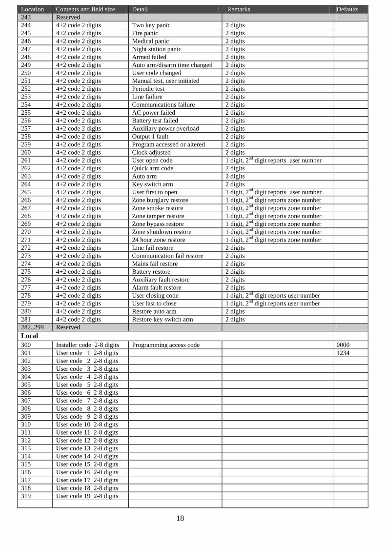
4 + 2 Reporting Codes
236 4+2 code 2 digits Zone burglary 1 digit, 2nd
digit reports zone number
237 4+2 code 2 digits Zone smoke 1 digit, 2nd
digit reports zone number
238 4+2 code 2 digits Zone tamper 1 digit, 2nd
digit reports zone number
239 4+2 code 2 digits Zone bypass 1 digit, 2nd
digit reports zone number
240 4+2 code 2 digits Duress 1 digit, 2nd
digit reports user number
241 4+2 code 2 digits Zone shutdown 1 digit, 2nd
digit reports zone number
242 4+2 code 2 digits 24 hour zone 2 digits, 2nd
digit reports zone number
18
Location Contents and field size Detail Remarks Defaults
243 Reserved
244 4+2 code 2 digits Two key panic 2 digits
245 4+2 code 2 digits Fire panic 2 digits
246 4+2 code 2 digits Medical panic 2 digits
247 4+2 code 2 digits Night station panic 2 digits
248 4+2 code 2 digits Armed failed 2 digits
249 4+2 code 2 digits Auto arm/disarm time changed 2 digits
250 4+2 code 2 digits User code changed 2 digits
251 4+2 code 2 digits Manual test, user initiated 2 digits
252 4+2 code 2 digits Periodic test 2 digits
253 4+2 code 2 digits Line failure 2 digits
254 4+2 code 2 digits Communications failure 2 digits
255 4+2 code 2 digits AC power failed 2 digits
256 4+2 code 2 digits Battery test failed 2 digits
257 4+2 code 2 digits Auxiliary power overload 2 digits
258 4+2 code 2 digits Output 1 fault 2 digits
259 4+2 code 2 digits Program accessed or altered 2 digits
260 4+2 code 2 digits Clock adjusted 2 digits
261 4+2 code 2 digits User open code 1 digit, 2nd
digit reports user number
262 4+2 code 2 digits Quick arm code 2 digits
263 4+2 code 2 digits Auto arm 2 digits
264 4+2 code 2 digits Key switch arm 2 digits
265 4+2 code 2 digits User first to open 1 digit, 2nd
digit reports user number
266 4+2 code 2 digits Zone burglary restore 1 digit, 2nd
digit reports zone number
267 4+2 code 2 digits Zone smoke restore 1 digit, 2nd
digit reports zone number
268 4+2 code 2 digits Zone tamper restore 1 digit, 2nd
digit reports zone number
269 4+2 code 2 digits Zone bypass restore 1 digit, 2nd
digit reports zone number
270 4+2 code 2 digits Zone shutdown restore 1 digit, 2nd
digit reports zone number
271 4+2 code 2 digits 24 hour zone restore 1 digit, 2nd
digit reports zone number
272 4+2 code 2 digits Line fail restore 2 digits
273 4+2 code 2 digits Communication fail restore 2 digits
274 4+2 code 2 digits Mains fail restore 2 digits
275 4+2 code 2 digits Battery restore 2 digits
276 4+2 code 2 digits Auxiliary fault restore 2 digits
277 4+2 code 2 digits Alarm fault restore 2 digits
278 4+2 code 2 digits User closing code 1 digit, 2nd
digit reports user number
279 4+2 code 2 digits User last to close 1 digit, 2nd
digit reports user number
280 4+2 code 2 digits Restore auto arm 2 digits
281 4+2 code 2 digits Restore key switch arm 2 digits
282..299 Reserved
Local
300 Installer code 2-8 digits Programming access code 0000
301 User code 1 2-8 digits 1234
302 User code 2 2-8 digits
303 User code 3 2-8 digits
304 User code 4 2-8 digits
305 User code 5 2-8 digits
306 User code 6 2-8 digits
307 User code 7 2-8 digits
308 User code 8 2-8 digits
309 User code 9 2-8 digits
310 User code 10 2-8 digits
311 User code 11 2-8 digits
312 User code 12 2-8 digits
313 User code 13 2-8 digits
314 User code 14 2-8 digits
315 User code 15 2-8 digits
316 User code 16 2-8 digits
317 User code 17 2-8 digits
318 User code 18 2-8 digits
319 User code 19 2-8 digits

19
Location Contents and field size Detail Remarks Defaults
320 User code 20 2-8 digits
321 User code 21 2-8 digits
322 User code 22 2-8 digits
323 User code 23 2-8 digits
324 User code 24 2-8 digits
325 User code 25 2-8 digits
326 User code 26 2-8 digits
327 User code 27 2-8 digits
328 User code 28 2-8 digits
329 User code 29 2-8 digits
330 User code 30 2-8 digits
331 User code 31 2-8 digits
332 User code 32 2-8 digits
333 User code 33 2-8 digits
334 User code 34 2-8 digits
335 User code 35 2-8 digits
336 User code 36 2-8 digits
337 User code 37 2-8 digits
338 User code 38 2-8 digits
339 User code 39 2-8 digits
340 User code 40 2-8 digits
341 User code 41 2-8 digits
342 User code 42 2-8 digits
343 User code 43 2-8 digits
344 User code 44 2-8 digits
345 User code 45 2-8 digits
346 User code 46 2-8 digits
347 User code 47 2-8 digits
348 User code 48 2-8 digits Temporary user code Deleted at midnight
349 User Code 1 1-8 digits User code options LED 1: on: bypass zones 1,6
350 User code 2 1-8 digits User code options LED 2: on: output 4 control from a
touch tone phone
1
351 User code 3 1-8 digits User code options LED 3: on: arm/disarm from a touch
tone phone
1
352 User code 4 1-8 digits User code options LED 4: on: arm/disarm lock code 1
353 User code 5 1-8 digits User code options LED 5: on: arm or disarm all areas or
disarm by selected area
1
354 User code 6 1-8 digits User code options LED 6: on: master user code 1
355 User code 7 1-8 digits User code options LED 7: on: arm only 1
356 User code 8 1-8 digits User code options LED 8: on: internal use 1
357 User code 9 1-8 digits User code options 1
358 User code 10 1-8 digits User code options Note that the # key must be pressed 1
359 User code 11 1-8 digits User code options after you have completed an LED 1
360 User code 12 1-8 digits User code options toggle selection. 1
361 User code 13 1-8 digits User code options 1
362 User code 14 1-8 digits User code options 1
363 User code 15 1-8 digits User code options 1
364 User code 16 1-8 digits User code options 1
365 User code 17 1-8 digits User code options 1
366 User code 18 1-8 digits User code options 1
367 User code 19 1-8 digits User code options 1
368 User code 20 1-8 digits User code options 1
369 User code 21 1-8 digits User code options 1
370 User code 22 1-8 digits User code options 1
371 User code 23 1-8 digits User code options 1
372 User code 24 1-8 digits User code options 1
373 User code 25 1-8 digits User code options 1
374 User code 26 1-8 digits User code options 1
375 User code 27 1-8 digits User code options 1
376 User code 28 1-8 digits User code options 1
377 User code 29 1-8 digits User code options 1
378 User code 30 1-8 digits User code options 1

20
Location Contents and field size Detail Remarks Defaults
379 User code 31 1-8 digits User code options 1
380 User code 32 1-8 digits User code options 1
381 User code 33 1-8 digits User code options 1
382 User code 34 1-8 digits User code options 1
383 User code 35 1-8 digits User code options 1
384 User code 36 1-8 digits User code options 1
385 User code 37 1-8 digits User code options 1
386 User code 38 1-8 digits User code options 1
387 User code 39 1-8 digits User code options 1
388 User code 40 1-8 digits User code options 1
389 User code 41 1-8 digits User code options 1
390 User code 42 1-8 digits User code options 1
391 User code 43 1-8 digits User code options 1
392 User code 44 1-8 digits User code options 1
393 User code 45 1-8 digits User code options 1
394 User code 46 1-8 digits User code options 1
395 User code 47 1-8 digits User code options 1
396 User code 48 1-8 digits User code options 1
397..399 Reserved Select Area
400 User code 1 1-4 digits User code areas select A-D LED 1: on: area A 1 = area A
401 User code 2 1-4 digits User code areas select A-D LED 2: on: area B
402 User code 3 1-4 digits User code areas select A-D LED 3: on: area C
403 User code 4 1-4 digits User code areas select A-D LED 4: on: area D
404 User code 5 1-4 digits User code areas select A-D
405 User code 6 1-4 digits User code areas select A-D Note that the # key must be pressed
406 User code 7 1-4 digits User code areas select A-D after you have completed an LED
407 User code 8 1-4 digits User code areas select A-D toggle selection.
408 User code 9 1-4 digits User code areas select A-D
409 User code 10 1-4 digits User code areas select A-D
410 User code 11 1-4 digits User code areas select A-D
411 User code 12 1-4 digits User code areas select A-D
412 User code 13 1-4 digits User code areas select A-D
413 User code 14 1-4 digits User code areas select A-D
414 User code 15 1-4 digits User code areas select A-D
415 User code 16 1-4 digits User code areas select A-D
416 User code 17 1-4 digits User code areas select A-D
417 User code 18 1-4 digits User code areas select A-D
418 User code 19 1-4 digits User code areas select A-D
419 User code 20 1-4 digits User code areas select A-D
420 User code 21 1-4 digits User code areas select A-D
421 User code 22 1-4 digits User code areas select A-D
422 User code 23 1-4 digits User code areas select A-D
423 User code 24 1-4 digits User code areas select A-D
424 User code 25 1-4 digits User code areas select A-D
425 User code 26 1-4 digits User code areas select A-D
426 User code 27 1-4 digits User code areas select A-D
427 User code 28 1-4 digits User code areas select A-D
428 User code 29 1-4 digits User code areas select A-D
429 User code 30 1-4 digits User code areas select A-D
430 User code 31 1-4 digits User code areas select A-D
431 User code 32 1-4 digits User code areas select A-D
432 User code 33 1-4 digits User code areas select A-D
433 User code 34 1-4 digits User code areas select A-D
434 User code 35 1-4 digits User code areas select A-D
435 User code 36 1-4 digits User code areas select A-D
436 User code 37 1-4 digits User code areas select A-D
437 User code 38 1-4 digits User code areas select A-D
438 User code 39 1-4 digits User code areas select A-D
439 User code 40 1-4 digits User code areas select A-D
440 User code 41 1-4 digits User code areas select A-D
441 User code 42 1-4 digits User code areas select A-D
442 User code 43 1-4 digits User code areas select A-D

21
Location Contents and field size Detail Remarks Defaults
443 User code 44 1-4 digits User code areas select A-D
444 User code 45 1-4 digits User code areas select A-D
445 User code 46 1-4 digits User code areas select A-D
446 User code 47 1-4 digits User code areas select A-D
447 User code 48 1-4 digits User code areas select A-D
448..450 Reserved Select Area
451 Zone area select 1-4 digits Zone 1 areas A-D LED 1: on: zone in area A 1 = area A
all zones 452 Zone area select 1-4 digits Zone 2 areas A-D LED 2: on: zone in area B
453 Zone area select 1-4 digits Zone 3 areas A-D LED 3: on: zone in area C 1
454 Zone area select 1-4 digits Zone 4 areas A-D LED 4: on: zone in area D 1
455 Zone area select 1-4 digits Zone 5 areas A-D 1
456 Zone area select 1-4 digits Zone 6 areas A-D Note that the # key must be pressed 1
457 Zone area select 1-4 digits Zone 7 areas A-D after you have completed an LED 1
458 Zone area select 1-4 digits Zone 8 areas A-D toggle selection. 1
459 Zone area select 1-4 digits Zone 9 areas A-D 1
460 Zone area select 1-4 digits Zone 10 areas A-D 1
461 Zone area select 1-4 digits Zone 11 areas A-D 1
462 Zone area select 1-4 digits Zone 12 areas A-D 1
463 Zone area select 1-4 digits Zone 13 areas A-D 1
464 Zone area select 1-4 digits Zone 14 areas A-D 1
465 Zone area select 1-4 digits Zone 15 areas A-D 1
466 Zone area select 1-4 digits Zone 16 areas A-D 1
Select Zone Options Part A
467 Zone options 1-8 digits Zone 1 options part A LED 1: on: Zone restore delay
(See Location 515)
1,2,6
zone 1
468 Zone options 1-8 digits Zone 2 options part A LED 2: on: Entry audible alert 1
469 Zone options 1-8 digits Zone 3 options part A LED 3: on: Key switch zone 1
470 Zone options 1-8 digits Zone 4 options part A LED 4: on: Chime mode 1
471 Zone options 1-8 digits Zone 5 options part A LED 5: on: Alternate entry zone 1
472 Zone options 1-8 digits Zone 6 options part A LED 6: on: Entry zone 1
473 Zone options 1-8 digits Zone 7 options part A LED 7: on: Closed loop zone
(no resistors required)
1
1
474 Zone options 1-8 digits Zone 8 options part A LED 8: on: Zone disabled 1
475 Zone options 1-8 digits Zone 9 options part A 1
476 Zone options 1-8 digits Zone 10 options part A Note that the # key must be pressed 1
477 Zone options 1-8 digits Zone 11 options part A after you have completed an LED 1
478 Zone options 1-8 digits Zone 12 options part A toggle selection. 1
479 Zone options 1-8 digits Zone 13 options part A 1
480 Zone options 1-8 digits Zone 14 options part A 1
481 Zone options 1-8 digits Zone 15 options part A 1
482 Zone options 1-8 digits Zone 16 options part A 1
Select Zone Options Part B
483 Zone options 1-8 digits Zone 1 options part B LED 1: on: Swinger shutdown 1, 5, 8
All zones
484 Zone options 1-8 digits Zone 2 options part B LED 2: on: Stay zone 1, 5, 8
485 Zone options 1-8 digits Zone 3 options part B LED 3: on: 24 hour active zone 1, 5, 8
486 Zone options 1-8 digits Zone 4 options part B LED 4: on: Smoke detector inactive
during smoke alarm reset
1, 5, 8
487 Zone options 1-8 digits Zone 5 options part B LED 5: on: Manual bypass 1, 5, 8
488 Zone options 1-8 digits Zone 6 options part B LED 6: on: Sequential entry 1, 5, 8
489 Zone options 1-8 digits Zone 7 options part B LED 7: on: Cross zones
(See Locations 622 & 623)
1, 5, 8
490 Zone options 1-8 digits Zone 8 options part B LED 8: on: Auto bypass 1, 5, 8
491 Zone options 1-8 digits Zone 9 options part B 1, 5, 8
492 Zone options 1-8 digits Zone 10 options part B Note that the # key must be pressed 1, 5, 8
493 Zone options 1-8 digits Zone 11 options part B after you have completed an LED 1, 5, 8
494 Zone options 1-8 digits Zone 12 options part B toggle selection. 1, 5, 8
495 Zone options 1-8 digits Zone 13 options part B 1, 5, 8
496 Zone options 1-8 digits Zone 14 options part B 1, 5, 8
497 Zone options 1-8 digits Zone 15 options part B 1, 5, 8
498 Zone options 1-8 digits Zone 16 options part B 1, 5, 8

22
Location Contents and field size Detail Remarks Defaults
Select Zone Filters
499 Zone 1 filter 1 digit Zone input sensitivity Erased: 10mS 4: 160mS
500 Zone 2 filter 1 digit Zone input sensitivity 1: 20mS 4: 160mS
501 Zone 3 filter 1 digit Zone input sensitivity 2: 40mS 4: 160mS
502 Zone 4 filter 1 digit Zone input sensitivity 3: 80mS 4: 160mS
503 Zone 5 filter 1 digit Zone input sensitivity 4: 160mS 4: 160mS
504 Zone 6 filter 1 digit Zone input sensitivity 5: 320mS 4: 160mS
505 Zone 7 filter 1 digit Zone input sensitivity 6: 640mS 4: 160mS
506 Zone 8 filter 1 digit Zone input sensitivity 7: 1.28 Seconds 4: 160mS
507 Zone 9 filter 1 digit Zone input sensitivity 4: 160mS
508 Zone 10 filter 1 digit Zone input sensitivity 4: 160mS
509 Zone 11 filter 1 digit Zone input sensitivity 4: 160mS
510 Zone 12 filter 1 digit Zone input sensitivity 4: 160mS
511 Zone 13 filter 1 digit Zone input sensitivity 4: 160mS
512 Zone 14 filter 1 digit Zone input sensitivity 4: 160mS
513 Zone 15 filter 1 digit Zone input sensitivity 4: 160mS
514 Zone 16 filter 1 digit Zone input sensitivity 4: 160mS
515 Numbers 0-9 Zone Restore timer by minutes Refer locations 467-482, LED 1 5
516...520 Reserved
521 Outputs 1-5 digits Siren Output areas LED1: on: area A events LED 1
522 Outputs 1-5 digits Aux. Output 1 areas LED2: on: area B events
523 Outputs 1-5 digits Aux. Output 2 areas LED3: on: area C events
524 Outputs 1-5 digits Aux. Output 3 areas LED4: on: area D events
525 Outputs 1-5 digits Aux. Output 4 areas LED5: on: system events only
LED6: on: system and area events
526 Number 0-9 Siren Output timer by minutes Multiply by 1 minute
Blank = Latched
5 minutes
all outputs
527 Numbers 0-9 Aux. Output 1 timer by minutes
528 Numbers 0-9 Aux. Output 2 timer by minutes 1-10 minutes ‘0’ = 10 minutes
529 Numbers 0-9 Aux. Output 3 timer by minutes
530 Numbers 0-9 Aux. Output 4 timer by minutes
531...535 Reserved
536 Outputs 1-5 digits Siren Output options See output options below
537 Outputs 1-5 digits Aux. Output 1 options See output options below
538 Outputs 1-5 digits Aux. Output 2 options See output options below
539 Outputs 1-5 digits Aux. Output 3 options See output options below
540 Outputs 1-5 digits Aux. Output 4 options See output options below
LED 1: on: Output mimics keypad beeps (entry/exit)
LED 2: on: Output disabled while disarmed
LED 3: on: Output disabled while stay armed
LED 4: on: Output disabled while away armed
LED 5: Spare
LED 6: Spare
LED 7: on: Smoke detector activation resets the voltage supply output for 4 seconds. After 20 seconds the panel re-checks if the
smoke detector is still in alarm. If not in alarm the panel waits a further 2 minutes then restores the zone. During the 2
minute wait mode the zone is disabled
LED 8: on Invert output
541..555 Reserved
Select Output Event
556 Outputs 1-5 digits Output event: Alarm LED 1: on: Siren output 1 = alarm
557 Outputs 1-5 digits Output event: Smoke LED 2: on: Aux. output 1
558 Outputs 1-5 digits Output event: Tamper LED 3: on: Aux. output 2
559 Outputs 1-5 digits Output event: Zone bypass LED 4: on: Aux. output 3
560 Outputs 1-5 digits Output event: Duress opening LED 5: on: Aux. output 4
561 Spare
562 Outputs 1-5 digits Output event: Two key panic
563 Outputs 1-5 digits Output event: Fire panic Note that the # key must be pressed
564 Outputs 1-5 digits Output event: Medical panic after you have completed an LED
565 Outputs 1-5 digits Output event: Night panic toggle selection.
567 Outputs 1-5 digits Output event: Arm fail
568 Outputs 1-5 digits Output event: Arm time changed

23
Location Contents and field size Detail Remarks Defaults
569 Outputs 1-5 digits Output event: User code changed
570 Outputs 1-5 digits Output event: User manual test
571 Outputs 1-5 digits Output event: Periodic test
572 Outputs 1-5 digits Output event: Line failure
573 Outputs 1-5 digits Output event: Communication
failure
574 Outputs 1-5 digits Output event: Mains failure
575 Outputs 1-5 digits Output event: Battery failure
576 Outputs 1-5 digits Output event: Auxiliary power
overload
577 Outputs 1-5 digits Output event: Siren output fault
578 Outputs 1-5 digits Output event: Program accessed
579 Outputs 1-5 digits Output event: Clock adjusted
580 Outputs 1-5 digits Output event: Opening/Closing
581 Outputs 1-5 digits Output event: Zone shutdown
582 Outputs 1-5 digits Output event: 24 hour activation
583..604 Reserved
605 Numbers 0-9 Exit delay area A times 10 secs Multiply by 10 seconds Area A 6 = 60 secs 606 Numbers 0-9 Exit delay area B times 10 secs Blank = Instant arm on exit
607 Numbers 0-9 Exit delay area C times 10 secs
608 Numbers 0-9 Exit delay area D times 10 secs
609 Numbers 0-9 Entry delay area A times 10 secs Multiply by 10 seconds Area A 2 = 20 secs 610 Numbers 0-9 Entry delay area B times 10 secs Blank = Instant activation on entry
611 Numbers 0-9 Entry delay area C times 10 secs
612 Numbers 0-9 Entry delay area D times 10 secs
613 Numbers 0-9 Alt entry delay area A times 10 secs Multiply by 10 seconds
614 Numbers 0-9 Alt entry delay area B times 10 secs Blank = Instant activation on entry
615 Numbers 0-9 Alt entry delay area C times 10 secs
616 Numbers 0-9 Alt entry delay area D times 10 secs
617 Numbers 0-9 Stay mode entry delay area A Multiply by 10 seconds
Blank = Instant activation on entry
618 Numbers 0-9 Stay mode entry delay area B
619 Numbers 0-9 Stay mode entry delay area C
620 Numbers 0-9 Stay mode entry delay area D
621 Numbers 0-9 Swinger shutdown after xx
activations
4
622 Numbers 0-9 Cross zones: Two activation’s
on either or any zones within xx
seconds time frame.
(See Location 623)
0 = None
1 = Same zone
2 = Different zones
3 = Same or different zones
0
623 Numbers 0-9 Cross zones timer Multiply by 10 seconds 0 = 10
Select Custom Key
624 Numbers 0-9 Custom Key F1 function 0: Disabled
625 Numbers 0-9 Custom Key F2 function 1: Night-arm area A only
626 Numbers 0-9 Custom Key F3 function 2: Panic, night panic on Nitewatch
627 Numbers 0-9 Nitewatch panic custom key
function
3: Fire event
4: Quick-arm all areas
628 Numbers 0-9 Nitewatch arm custom key
function
5: Quick-arm area A
6: Quick-arm area B
7: Quick-arm area C
8: Quick-arm area D
629..650 Reserved
Select Auto Arm/Disarm by Area
651 Numbers 1-8 Auto-arm/disarm LED 1: on: area A
LED 2: on: area B
LED 3: on: area C
LED 4: on: area D
LED 8: on: 5 minute pre-alert beep

24
Location Contents and field size Detail Remarks Defaults
Select Auto Arm if no Activity
652 Numbers 1-8 Auto arm if no activity LED 1: on: area A
LED 2: on: area B
LED 3: on: area C
LED 4: on: area D
LED 8: on: 5 minute pre-alert beep
653 Time HH:MM Auto arm time if no activity HHMM (24 hour format)
654 Force arming 1-4 Select by area LED 1: on: area A
LED 2: on: area B
LED 3: on: area C
LED 4: on: area D
1,2,3,4
655..660 Reserved
661 Numbers 1-8 Miscellaneous options Select Options
LED 1: on: 50/60Hz select. off = 60Hz 1
LED 2: on: Zone LED’s latch while
area not armed
LED 3: on: Wrong code lockout after 6
attempts
LED 4: off: enable factory default reset
with a keypad command
LED 5: on: Single 4K7 resistor zones,
tampers disabled
LED 6: on: Not used
LED 7: on: Auto arm mode: on = away
arm; off = night arm
LED 8: on: Arm all areas function (9#)
disabled
Note that the # key must be pressed
after you have completed an LED
toggle selection.

25
Programming Explanations
Entering Program Mode from the Keypad
To enter program mode enter <NNNN> (installer programming access code) (default 0000) then press the # key. The
mains power cord symbol will turn off on the icon LCD keypad. You are now in ‘Address Mode’. You may now enter a
location number and press #. The exclamation symbol will appear on the icon LCD keypad indicating you are now in
‘Data Entry Mode’. Data may now be entered into this location. As data is entered, the exclamation symbol will flash
indicating data is being entered. After you have entered data at a location, you MUST press the # key to store that data.
Entering Data
Example: The following enters the first user code 1234.
<installer code> # <location number> # <new user code> #
<0000> # <301> # <1234> #
The display screen is now blank and waiting for the next location selection. You can now select another location followed
by #. After entering data at any location, the # key MUST be pressed to store that data.
At locations where multiple data entries are programmed (options), the keypad keys act as an electronic switch which can
select or de-select zone options. If you are programming Location 467 for example (zone 1 options) and you press keys 1,
2, 4 and 6, these keypad zone lamps will turn on. These are the options selected for zone 1. If zone 4 is pressed in error, then
simply press key 4 again and the zone 4 indicator lamp will turn off. Enter the # key to store your selection in memory.
To exit program press ** (star star)
Erasing a Memory Location
To erase data from a selected location, press and hold the ‘0’ key until a second beep is heard, then press the # key. This is
confirmation that the location is now erased. This command also applies to multiple data entry locations.
Communication Programming
Telephone Numbers: Locations 1-6
All six telephone numbers can be programmed to report to a central monitoring station, home telephone, mobile phone or
numeric pager. Telephone numbers of up to 20 digits can be entered. Telephone numbers are programmed by accessing
program mode using the installer code.
The first two telephone numbers can also be changed by the end-user (call diversion) when ‘home dial’ has been selected.
If ‘home dial’ is selected, only a zone activation or panic alarm will report to the programmed telephone. All other reports
will be ignored. On activation, the panel will call the user and a siren warble tone will be heard, then a pause, followed by a
series of beeps. The number of beeps identifies the zone that has activated. The alarm control will continue sounding siren
warble then beeps…siren warble then beeps for approximately 20 seconds. To cancel the call the user presses the *key on
any DTMF or mobile phone. This will terminate the call and a hang up tone will be heard if the *command has been
successful. This will prevent the alarm control calling any secondary programmed telephone numbers. If the initial call is
not acknowledged by pressing the *key, the panel will search for a secondary number to call and repeat the process.
Example of Home Dialling
If zone 3 activates and calls the first telephone number a siren warble then zone beeps will be heard and repeated for 20
seconds. Data must be entered in 4+2 Locations: alarms / alarm restores for the panel to report. The Contact ID
reporting codes must NOT be deleted. In home dial mode, if the call has not been acknowledged by the user with the *key
command on their DTMF telephone, the icon LCD keypad will display the triangular system fault symbol. Entering the *83
command (miscellaneous alarm recall) will display zone LED 4, indicating the panel failed to communicate. This can be
erased by entering a valid user code to arm and disarm the system. To abort a home dialling call the user can enter *59 then
<master user code> # to cancel the call.

26
Pager Calling
Activation reports to a pager are sent in the 4+2 format and display account number plus two reporting digits. Enter a 5 at
Location 7, pager selection. At Locations 13 to 16 enter account numbers and at Locations 236-247 program reporting
codes. Only Alarms and Panics are reported. For alarm restores enter the restore reporting digits for the selected locations
at Locations 266-271.
After the pager has been called a delay is required on most pager networks before the panel data is sent. Entering *3 (13)
after the pager number provides a 3 second delay. Entering *3 *3 after the pager number provides a 6 second delay. To
program a space between the customer ID number and the two reporting digits enter an *1 (11) at Location 20.
Example: Location 1: Enter pager number 026 326 4341 [*3] [*3] with a 6 second delay before sending report.
(the delay entry is achieved by pressing the [* + 3] keys together)
Location 7: Enter a 5 (pager format)
Locations 13 – 16: Enter customer ID number
Location 20: Enter *1 (eleven) for a space between the customer ID and reporting codes.
Select Dialling Format: Locations 7-12
Select the format the panel is to send.
Account Numbers: Locations 13-16
Enter the customer account number (4 digits) for area’s ‘A’ to ‘D’.
Non ‘Alarm’ Reports: Locations 17-18
Assign non alarm reports to secondary telephone numbers.
Pager Start Character: Location 19
This is sent before any other digit.
Pager Space Character: Location 20
This is sent between the account number and the reporting code. Enter *1 (11) for a space between the account number and
the reporting code.
Pager End Character: Location 21
This is sent after all other digits.
Fax / Answer Phone Defeat: Location 22
To defeat a fax or answer phone, call the panel and after two rings hang up. Now recall the panel within 60 seconds and the
panel will answer after the second ring.
Call Attempts: Locations 40-45
This is the number of call attempts the panel will make for a telephone number before it moves to the next number. A value
must be entered for the communicator to make a call. If these locations are empty, the communicator is disabled.
Dialling Cycles: Location 46
The number of times the communicator will pass through the phone list.
Call Attempt Timer (Anti Jam): Location 47
After making a call, this is the time the panel will wait for the central monitoring station or private telephone number to send
an acknowledgement before aborting the call and making another attempt. If programmed to call a private telephone (siren
warble), the alarm communicator will wait for the * key command before aborting the call.

27
Answer after XX Rings: Location 48
This is the number of rings before the panel will answer the call. For answer phone / fax defeat, call the panel, allow 2 rings
and hang-up, then re-call the panel within 60 seconds and the panel will answer on the first ring.
Dialling Mode: Location 49
Select the dialling format.
Areas to Report: Locations 56-61
Assign the areas to report to the telephone number the panel will call.
Test Signal: Location 62
This is the time in 24 hour format (HHMM) the test signal will be sent to the central monitoring station. If days or hours
have been altered, Location 63, (first time test) then Location 62 must be reprogrammed to restart the days / hours count.
Hours Between Test Calls: Location 63
This is the time period after which the first test call will be generated after the programmed time set at Location 62. All
subsequent reports will call at this programmed time.
Reporting Times
Blank No report
1 3 Hours
2 6 Hours
3 12 Hours
4 24 Hours
5 48 Hours
6 72 Hours
7 96 Hours
8 1 Week
9 2 Weeks
0 1 Month
Communication Option: Location 65
An opening will be sent after an alarm, when opening/closing reports are programmed not to report to the central
monitoring station.
Upload / Download Password: Location 66
Enter a 4 digit unique code that Microcom II will validate to ensure that the downloading computer is authorised to access
the panel. The remote computer must have the same 4 digit code programmed to gain access.
Line Test Mode: Location 67
Select when the panel will test the telephone line.
Event Reporting Codes (Contact ID): Locations 200-229
These locations are used for the Contact ID reporting codes. If the panel is to communicate in Contact ID format these
locations are pre-programmed and it is not necessary to enter Contact ID codes. Erasing one of these locations disables
reporting of all events in ALL formats.
Ademco 4+2 Reporting: Locations 236-281
These locations are used for reporting in the Ademco 4+2 format. Enter 2 digits at these locations. Request the 4+2 reporting
template from the central station that will monitor the alarm. Erasing the data at any of these locations will disable that
report. See the table for entering hexadecimal reporting codes on page 31.

28
Local Programming
Emergency Access to Program Mode: Location 661
If the Installer programming code is lost, remove all power from the panel and then re-apply mains, pressing keys
1+3 simultaneously, the panel will switch into program mode and you can now select a location to commence
programming. At Location 661, LED 4 must be OFF.
Installer Access Programming Code: Location 300
Enter your unique installer code for accessing the panel’s program mode, default (0000)
User Codes: Locations 301-348
Each of the 48 user codes can be 2 to 8 digits in length. After entering the user code press the # key and the panel will emit 2
beeps and step to the next location. Select user options at Locations 349-396 and Locations 400-447. User 48 is a
temporary code that disables at midnight.
User Code Options: Locations 349-396
Assign the user code attributes for user code commands.
LED 1: on: Bypass zones
LED 2: on: Turns output 4 on / off from a touch tone phone
LED 3: on: Arm / Disarm from a touch tone phone
LED 4: on: Arm / Disarm lock code (If armed by this code no other code can disarm)
LED 5: on: Arm and disarm all areas or disarm by selected area (see example below)
LED 6: on: Master user
LED 7: on: Arm only
LED 8: Internal use
Arm and Disarm all Areas or Disarm Selected Areas
If programmed at Locations 349 to 396 (user code options) LED 5 on, the user can arm all areas, disarm all areas or disarm
selected areas. Enter a valid enabled user code: <XXXX> # panel will arm all areas or disarm all armed areas.
When all areas are armed select the area to disarm. Enter a valid enabled user code: <XXXX> 1 # disarms area ‘A’
<XXXX> 4 # disarms area ‘D’
Assign User Code to Areas: Locations 400-447
Enter the area ‘A’ to ‘D’ that the user code controls. A fixed internally programmed code of 9 # will arm all areas, or arm all
disarmed area
Assign Zones to Areas: Locations 451-466
Enter the area ‘A’ to ‘D’ assigned to each zone. When selecting a zone for common entry, the zone allocated as the
entry/exit zone should be assigned to those areas.
Example: Zone 1 is a common entry/exit zone for area ‘A’ and ‘B’. At Location 451 enter a 1 and 2 to enable both area ‘A’
and ‘B’ to have a common entry path through zone 1. The first to enter and disarm either area ‘A’ or ‘B’ will turn off zone 1.
The first to exit will arm their area with the exception of zone 1. The last to exit will arm their area including zone 1.
Zone Options: Locations 467-498
Select zone options part ‘A’ and part ‘B’ at these locations.
Example: To program a smoke zone with a 4 second reset.
Locations 483 to 498: set zone as smoke, LED 4 on
Location 521: assign alarm output to area
Location 525: assign auxiliary output 4 to area
Location 540: assign auxiliary output 4 to smoke reset pulse, LED 7 on.
Location 557: assign alarm output to smoke
Result: The smoke zone activates, the auxiliary output turns on for 4 seconds and the panel waits for the smoke detector
stabilise time, then checks if the smoke zone is still in alarm. If the zone is still in alarm, then the output activates and sends
a report to the central monitoring station.

29
Zone Filters: Locations 499-514
Select the zone input sensitivity from 10mS to 1.28 seconds. This is the zone response time. Response times of less than
160mS should be reserved only for special sensors such as vibration sensors.
Assign Outputs to Areas: Locations 521-525
Assign areas ‘A’ to ‘D’ to outputs 1 to 5 for alarm and system events.
Output Timers: Locations 526-530
Select output timers to reset after an alarm. Single digit 1 to 9 in minutes (0 is 10 minutes). Blank is output latched. The
output only resets when a valid user code is entered.
Output Options: Locations 536-540
Select options for how outputs 1 to 5 behave.
Output Events: Locations 556-582
Assign outputs 1 to 5 for panel activation events.
Exit Delay Time: Locations 605-608
Enter the exit delay time for areas ‘A’ to ‘D’ (10 second multiples).
Blank = instant arm, no delay on exit.
Entry Delay Time: Locations 609-612
Enter the entry delay time for areas ‘A’ to ‘D’ (10 second multiples).
Blank = no delay, instant alarm on entry.
Alternate Entry Delay: Locations 613-616
Enter a second entry delay time for areas ‘A’ to ‘D’ (10 second multiples).
Blank = no alternate delay, instant alarm on entry.
Night Arm Entry Delay (Stay Mode): Locations 617-620
Enter the entry delay time when entering a night zone (10 second multiples).
Blank = no delay, instant alarm on entry.
Swinger Shutdown: Location 621
Enter a single digit in the range 1 to 9. This is the number of activations on any one zone before the zone is disabled. The
swinger shutdown count is for one arming cycle. Disarming the panel resets the swinger shutdown count.
Cross Zones (Double Knock): Location 622
Enter a single digit for two activations on the same zone, different zones or either the same or different zones within an XX
second time before the alarm activates. If the timer resets before a second activation within the programmed time, the zone
will restore and wait for a further two activations. When selecting double knock zones it is recommended that the detection
devices are space protection devices such as PIR’s etc. It is not recommended that zones protecting doors fitted with reed
switches are selected as double knock zones.
Cross Zone Timer: Location 623
Enter a single digit for the cross zone timer (10 second multiples).
Custom Keys: Locations 624-628
Select the operation of the special custom keys (F1, F2, F3) for one-key-commands.

30
Auto Arm and Auto Disarm: Location 651
Select by area(s) ‘A’ to ‘D’ for the panel to auto arm/auto disarm. Auto arm and auto disarm times are entered by the user
with the *51 and *52 commands followed by a master user code. To program an area auto arm / disarm time a valid master
user code assigned to the area to auto arm / disarm must be used. If more than one area is to auto arm /disarm at the same
time then a valid master user code assigned to those areas must be used. See Locations 400-447.
Example: Master user code 1234 assigned to area ‘A’
Master user code 4321 assigned to area ‘B’
Master user code 2580 assigned to areas ‘C’ and ‘D’
*51 <1234> # <17:00> # to auto arm area ‘A’
*52 <1234> # <08:00> # to auto disarm area ‘A’
*51 <4321> # <18:30> # to auto arm area ‘B’
*52 <4321> # <09:30> # to auto disarm area ‘B’
*51 <2580> # <19:00> # to auto arm areas ‘C’ and ‘D’
*52 <2580> # <08:30> # to auto disarm areas ‘C’ and ‘D’
The times selected will operate every 24 hour period or until such time as the function is disabled or a new time setting is
programmed. If a pre-alert has been selected, the keypad will emit a series of beeps 5 minutes before arming. To abort auto
arming during the pre-alert period for that day, press any key on the assigned keypad. In the event of a total loss of power to
the panel, the real time must be re-programmed when power is restored with the *50 master user code command.
Auto Arm if No Activity: Location 652
Select the area(s) ‘A’ to ‘D’ the panel will arm when NO activity is detected after the programmed NO activity time has
elapsed at Location 653. If a pre-alert has been selected, the keypad will emit a series of beeps for 5 minutes prior to
arming. Pressing any key on the assigned keypad, or entering the assigned area programmed for NO activity arming, will
abort the arming cycle and reset the NO activity count down timer.
Auto Arm Time with No Activity: Location 653
Enter the time HHMM (24 hour format) when the panel will arm after sensing no activity. If a zone(s) is in an alarm state
when the panel is disarmed, the no activity timer is disabled until the zone(s) is restored. When the zones restore the activity
timer will commence and the panel will arm after the no activity programmed time.
Force Arming: Location 654
Select the area(s) A to D that allow arming when a zone or zones within that area are in alarm. If at Locations 483 to 498,
LED 8 is turned on, any zones still in alarm after the exit delay has expired will auto isolate. If this option has not been
selected the panel will refuse to arm when an alarm condition exists within that area or the alarm will activate after the exit
delay time has expired.
Miscellaneous Options: Location 661
Select the panel options at this location.
Disable Double End of Line Tampers: Location 661
If at Location 661, LED 5 is turned on, double end of line tampers can be disabled for all zones and single 4k.7
resistor alarm zones established.
Entering Hexadecimal Characters
Press and hold the * (star) key together with the corresponding digit.
Entry digit Character
*0 A
*1 B
*2 C
*3 D
*4 E
*5 F

31
Reading Programmed Data from the Keypad.
Reviewing numeric entries: in programming mode location data will be displayed by the keypad as a digital value. Each
digit will display for 1 second and then step to the next digit automatically; a beep will sound every time a new digit is
displayed. Locations may be selected at any point and the contents viewed, programmed and / or modified. The programmed
data displayed is either decimal or hexadecimal. To read the values refer to the ‘lookup table’ below.
LED LED LED LED DEC HEX 1 2 3 4
0 0
X 1 1
X 2 2
X X 3 3
X 4 4
X X 5 5
X X 6 6
X X X 7 7
X 8 8
X X 9 9
X X 10 A
X X X 11 B
X X 12 C
X X X 13 D
X X X 14 E
X X X X 15 F
The Keypads
A maximum of four 16 zone LCD or LED keypads may be connected to the Z16040C controller. Each keypad can
operate one or up to four areas. A keypad’s audible alert and visual display for selected areas is set by a four
position dipswitch on the back of the each keypad.
1 On = area ‘A’ visual display / beeper alert
2 On = area ‘B’ visual display / beeper alert
3 On = area ‘C’ visual display / beeper alert
4 On = area ‘D’ visual display / beeper alert
There are three ‘custom keys’ F1, F2 and F3 for fast key commands.
Icon LCD Keypad
The LCD keypad gives full visual and audible indication of the alarm status. The keypad has five graphic symbols,
an area identifier and 16 zone indicators.
The power lead symbol is on when mains power is present and flashes together with the
system fault symbol when there has been a mains failure.
The system fault symbol flashes when there has been a system fault condition, or a system
two key panic command has been initiated.
The bell symbol flashes when an alarm condition has occurred or a system two key panic has
been activated.
The moon symbol is displayed when the system is night armed.
The padlock symbol is displayed ‘unlocked’ when the system is disarmed or in programming
mode and ‘locked’ when the system is away armed or night armed.
The area identifier symbol is the four segment box at the lower right hand side of the LCD
display. This symbol displays the area(s) that is away armed or night armed. In non-partitioned
systems only Area A is displayed.
32
Zone and Graphic LCD keypad Indicators
The zone indicator lamps are displayed as numbers 1 through 16 on the top two lines of the LCD keypad. The
arming zone numbers will be displayed when an away arm or night arm command has been initiated. During the
exit delay the keypad will also display the ‘padlock’ symbol flashing in an alternating lock and unlock state and the
area identifier box will show the area(s) that are arming. A fast pulse audible tone will be heard.
In the event of a system alarm, the keypad will display the full status of the alarm condition. The zone indicators,
power lead, system fault, bell and padlock symbols will flash together with the area identifier, indicating the area in
which the zone(s) has activated.
If your system is partitioned into multiple areas, then only the user codes assigned to the designated area(s) are
functional for that area(s). All zones assigned to an area are visually and audibly signalled on the keypad(s)
programmed for that area(s).
Sixteen Zone LED Keypad
The LED keypad gives full visual and audible indication of the status of your alarm. The keypad has four area
identifiers, AC power, night arm and 16 zone indicators.
The green AC symbol is on when mains power is present and flashes when there has been a mains failure.
The AC symbol flashes fast when there has been a system fault condition, or a system two key panic command.
The area identifiers (S1, S2, S3, S4) flash when an alarm condition has occurred within that area(s) or a system
two key panic has been activated.
The yellow Nite symbol is on when the system is night armed.
The area identifiers (S1, S2, S3, S4) flash when arming an area(s) and remain steady on when an area has armed.
Zone LED keypad Indicators
The zone indicator lamps are displayed as numbers 1 through 16 on the LED keypad. The arming zones will be displayed
when an away arm or night arm command has been initiated. A fast pulse audible tone will be heard.
In the event of a system alarm, the keypad will display the full status of the alarm condition. The zone indicators will
flash together with the area identifier, indicating the area in which the zone(s) has activated.
If your system is partitioned into multiple areas, then only the user codes assigned to the designated area(s) are
functional for that area(s). All zones assigned to an area are visually and audibly signalled on the keypad(s)
programmed for that area(s).

33
Technical Specifications
AC Input………………………14.8 VAC from transformer (Do NOT exceed).
Accessory Power……………...13.8 VDC, 500 mA total drain.
Battery Capacity………………7.3 A/H.
Battery Fuse…………………..3 Amp fast blow.
Siren Output…………………..Max: 1.5 Amps DC to non inductive load.
Aux: 1 Output…………………Max: 250 mA Sink output.
Aux: 2 Output…………………Max: 250 mA Sink output.
Aux: 3 Output…………………Max: 250 mA Sink output.
Aux: 4 Output…………………Max: 250 mA Sink output.
There are 38 events/options that can be assigned to the outputs. Assign areas at Locations 521 to 525 and the
options and events at Locations 536 to 582. Output timers are programmed at Locations 526 to 530.
Current Rating
The following table shows the approximate current draw for micron accessories fitted to the Scorpion Z16040
alarm control.
It is important to calculate total current draw when installing a micron system to ensure power supply is not
overloaded during activation.
Accessory Current Draw Control PCB and LED Keypad 200mA (All LED’s on)
Control PCB and LCD Keypad 210mA (All LED’s on)
LCD Keypad 70mA (All LED’s on)
LED Keypad 60mA (All LED’s on)
iQ50 Passive infra-red 25mA (Activated)
PXI Passive infra-red (Pet sensor) 20mA (Activated)
ET Passive infra-red (Environmentally tolerant) 20mA (Activated)
GEM Passive infra-red 25mA (Activated)
Nitewatch Remote station (Home mode) 40mA
External siren 625mA (Active)
Piezo internal siren 200mA (Active)
RCM1 / RCM24 Wireless receiver module 35mA
Speech communicator 80mA (Active)
Smoke detector 30mA (Active)
EOL Resistors
All zones are actively scanning both zone and tamper detection with double end of line resistors. A 4.7k resistor is
in series with the tamper and a 4.7k resistor is in parallel with the zone. The tamper is a 24 hour active circuit
and when activated will generate an alarm in the armed or disarmed state.
Connection to Mains Earth
For protection against the hazards of over voltages and damage to the alarm circuit board
it is essential that the green earth wire from the printed circuit board is connected to a
secure mains earth point.

34
Telecom Waiver
The grant of a Telepermit for any item of terminal equipment indicates only that Telecom has accepted that the item
complies with the minimum conditions for connection to its network. It indicates no endorsement of the product by
Telecom, nor does it provide any sort of warranty. Above all, it provides no assurance that any item will work
correctly in all respects with another item of Telepermitted equipment of a different make or model, nor does it
imply that any product is compatible with all of Telecom’s network services.
This equipment is set up to carry out test calls at pre-determined times. Such test calls will interrupt any other calls
that may be set up on the line at the same time. The timing set for such test calls should be discussed with the
installer. The timing set for test calls from this equipment may be subject to ‘drift’. If this proves to be
inconvenient and your calls are interrupted, then the problem of timing should be discussed with the equipment
installer. The matter should NOT be reported as a fault to Telecom Faults Service.
Recommended Method of Connection to the Telecom Network
1 Fit an RJ31X Single Line Junction Box alongside the existing Telecom Master Socket.
2 Locate the telephone line wires, which are connected to terminals 2 and 5 in the Telecom Master Socket
and make some form of identifying mark on the wire connected to terminal 2.
3 Disconnect the 2 telephone line wires from terminals 2 (marked wire) and 5 in the Telecom Master Socket
and connect them to terminals 4 (marked wire) and 5 in the RJ31X Junction Box.
4 Add a connecting wire from terminal 1 RJ31X Junction Box to terminal 5 in the Telecom Master Socket.
5 Add a connecting wire from terminal 8 in the RJ31X Junction Box to terminal 5 in the Telecom Master
Socket.
6 Check that all other wires within the Telecom Master Socket are connected securely, especially if these have
been disturbed during the re-wiring.
7 Check that all existing telephone equipment still functions correctly.
8 Plug the line cord from the security system into the socket on the RJ31X Junction Box.
9 Check again that all existing telephone equipment still functions correctly.
10 Check that the security system equipment functions correctly.
This equipment must not be programmed for decadic (pulse) dialing because its characteristics are incompatible
with the telephone exchanges in New Zealand. DTMF (tone) dialing is considerably faster and is fully compatible

35
Notes
36
GUARANTEE
1. Subject to clause 2 below, Micron guarantees this product against defects in materials
and workmanship for a period of 24 months from the date of delivery to the purchaser
as follows:
(a) Micron will repair or replace free of charge any goods or part thereof found to be
defective by reason of faulty material or workmanship.
(b) The purchaser must give Micron notice of the alleged defect within 14 days of it
becoming apparent and must return the defective goods or part thereof to Micron.
2. This guarantee does not apply or extend to:
(a) Any product altered or repaired by any person other than Micron so as in Micron’s
sole judgement to adversely affect the product.
(b) Damage, malfunction or failure arising from accident, misuse or misapplication,
neglect, modifications, use of unauthorised replacement parts or accessories, exceeding the
specific ratings, improper voltage or connection of any wire to any to any part of the circuit board
other than the terminal block.
(c) Any product where the rating label or serial number is removed or altered.
(d) Any consequential or indirect loss.
Designed and manufactured by: