microcontroller systems - unc charlottesjkuyath/elet3232/topics/topic 4a-armi… · microcontroller...
TRANSCRIPT
ELET 3232Topic 4a: ARM Programmer’s Model
Microcontroller Systems
with slides by Peng-Sheng Chen2/1/2011 1

Introduction The ARM processor is easy to program at the
assembly level. (It is a RISC) Of course, it depends on how you define easy
2/1/2011 2
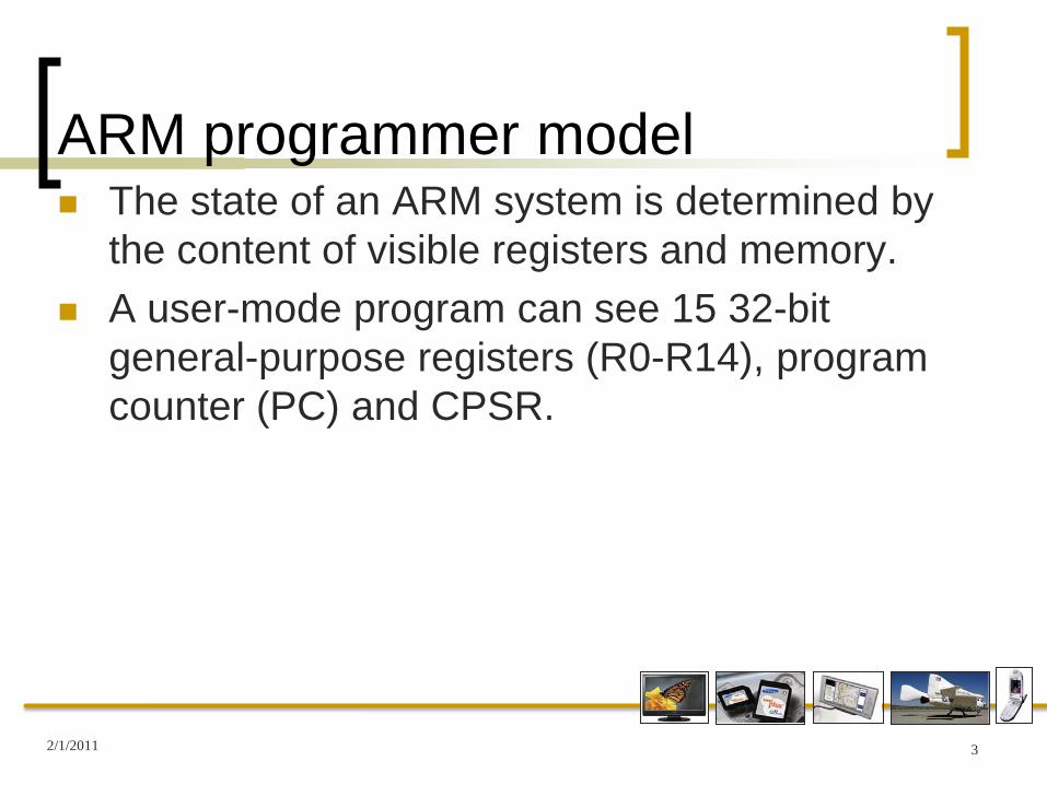
ARM programmer model The state of an ARM system is determined by
the content of visible registers and memory. A user-mode program can see 15 32-bit
general-purpose registers (R0-R14), program counter (PC) and CPSR.
2/1/2011 3
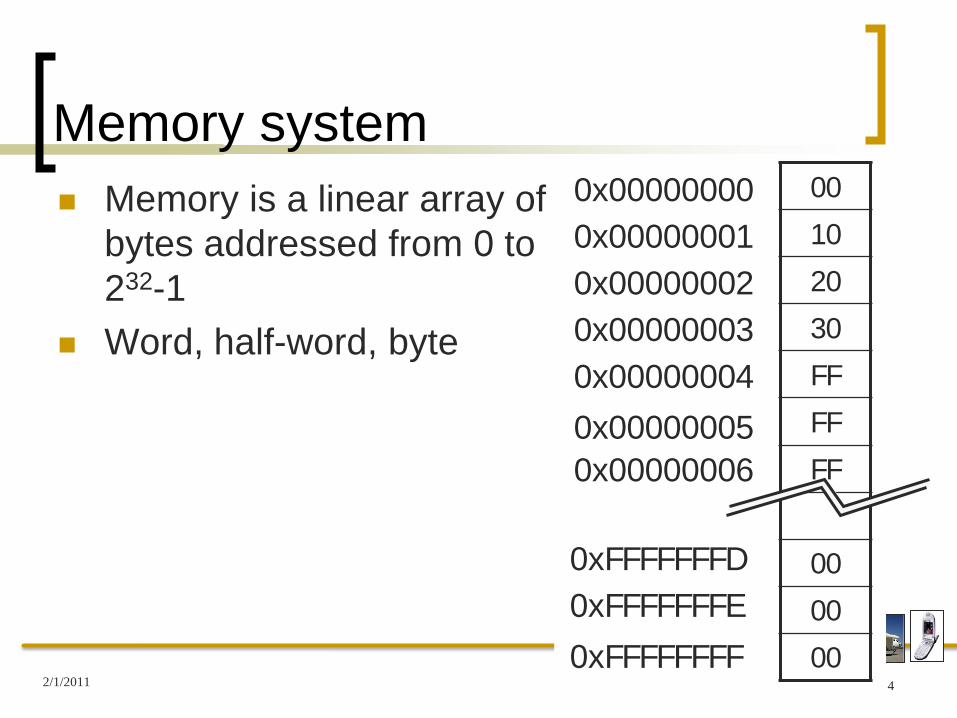
Memory system Memory is a linear array of
bytes addressed from 0 to 232-1
Word, half-word, byte
00
10
20
30
FF
FF
FF
00
00
00
0x000000000x000000010x000000020x000000030x000000040x000000050x00000006
0xFFFFFFFF0xFFFFFFFE0xFFFFFFFD
2/1/2011 4

Byte ordering Big Endian
Least significant byte has highest address
Word address 0x00000000 Value: 00102030
Little Endian Least significant byte has
lowest addressWord address 0x00000000 Value: 30201000
00
10
20
30
FF
FF
FF
00
00
00
0x000000000x000000010x000000020x000000030x00000004
0x000000050x00000006
0xFFFFFFFF
0xFFFFFFFE0xFFFFFFFD
2/1/2011 5

ARM programmer model00
10
20
30
FF
FF
FF
00
00
00
0x000000000x000000010x000000020x000000030x000000040x000000050x00000006
0xFFFFFFFF0xFFFFFFFE0xFFFFFFFD
R0 R1 R2 R3
R4 R5 R6 R7
R8 R9 R10 R11
R12 R13 R14 PC
2/1/2011 6
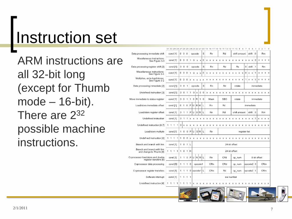
Instruction setARM instructions are all 32-bit long (except for Thumb mode – 16-bit). There are 232
possible machine instructions.
2/1/2011 7
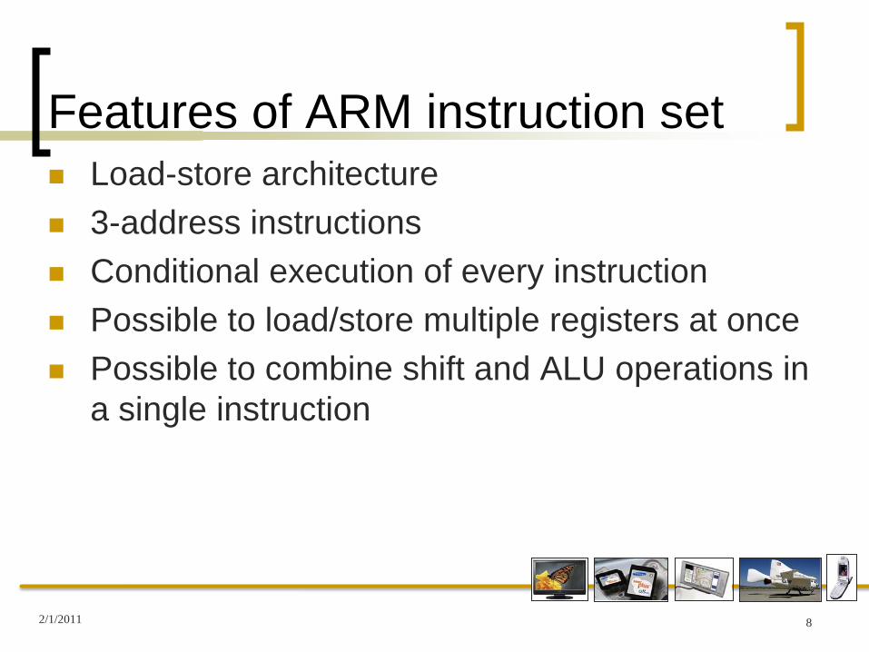
Features of ARM instruction set Load-store architecture 3-address instructions Conditional execution of every instruction Possible to load/store multiple registers at once Possible to combine shift and ALU operations in
a single instruction
2/1/2011 8

Instruction set Data processing Data transfer Flow control
2/1/2011 9

Data Processing Instructions All operands are 32 bits wide
Data could be in registers Data could be specified in the instruction itself
The result is 32 bits wide Placed in a register Exception: long multiply: result is 64 bits wide
Uses a 3-address format Operands and result register are specified
independently
2/1/2011 10
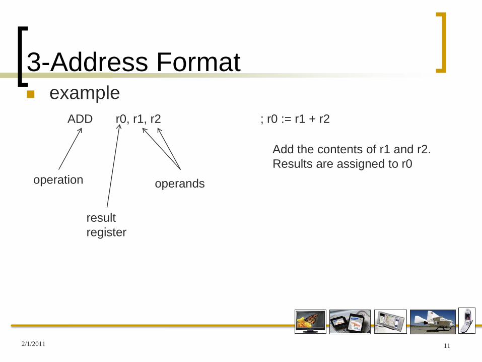
3-Address Format example
2/1/2011 11
ADD r0, r1, r2 ; r0 := r1 + r2
operation
resultregister
operands
Add the contents of r1 and r2. Results are assigned to r0
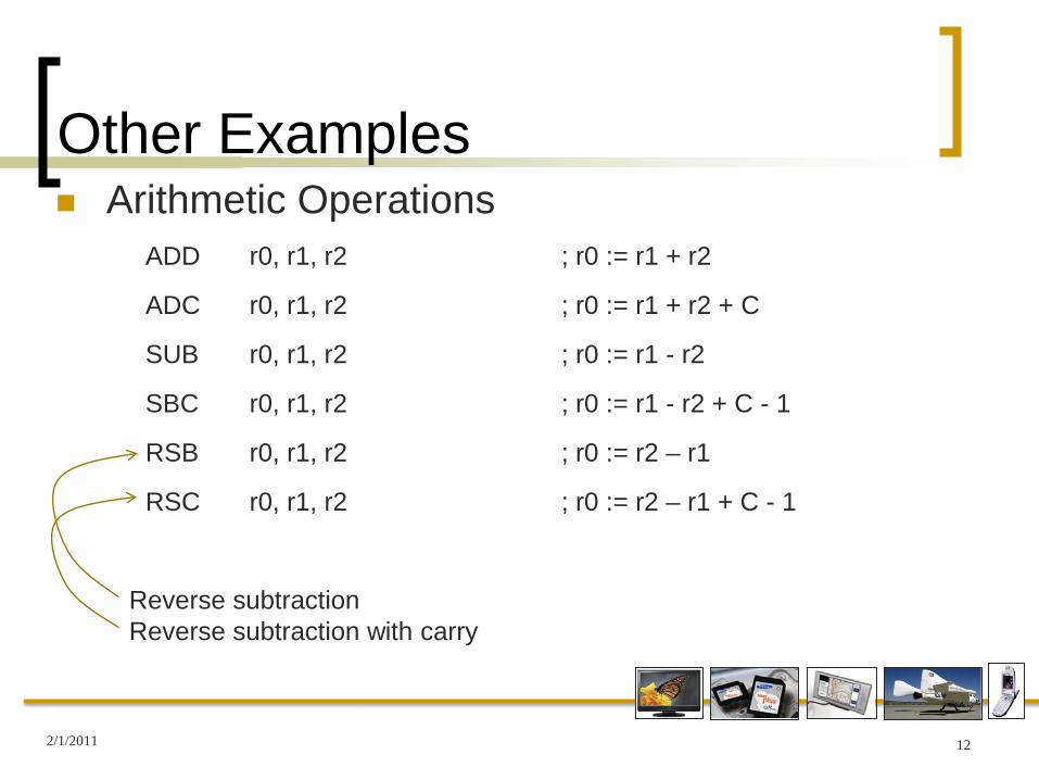
Other Examples Arithmetic Operations
2/1/2011 12
ADD r0, r1, r2 ; r0 := r1 + r2
ADC r0, r1, r2 ; r0 := r1 + r2 + C
SUB r0, r1, r2 ; r0 := r1 - r2
SBC r0, r1, r2 ; r0 := r1 - r2 + C - 1
RSB r0, r1, r2 ; r0 := r2 – r1
RSC r0, r1, r2 ; r0 := r2 – r1 + C - 1
Reverse subtractionReverse subtraction with carry

Other Examples Bit-Wise Logical Operations
2/1/2011 13
AND r0, r1, r2 ; r0 := r1 AND r2
ORR r0, r1, r2 ; r0 := r1 OR r2
EOR r0, r1, r2 ; r0 := r1 XOR r2
BIC r0, r1, r2 ; r0 := r1 AND not r2

Other Examples Bit-Wise Logical Operations
2/1/2011 14
AND r0, r1, r2 ; r0 := r1 AND r2
ORR r0, r1, r2 ; r0 := r1 OR r2
EOR r0, r1, r2 ; r0 := r1 XOR r2
BIC r0, r1, r2 ; r0 := r1 AND not r2
If r1 = 55x (0101 0101) and r2 = 41x (0100 0001)
Not r2 = 1011 1110
r1 AND not r2 = 0001 0100
So, r2 specifies (by the 1s) which bits in r1 to clear
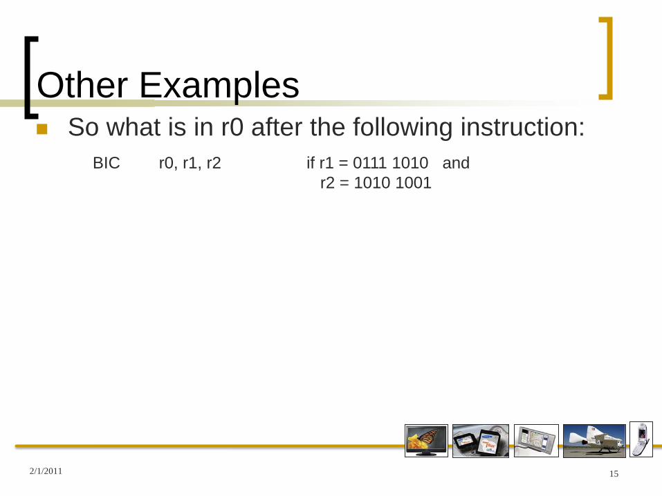
Other Examples So what is in r0 after the following instruction:
2/1/2011 15
BIC r0, r1, r2 if r1 = 0111 1010 and r2 = 1010 1001

Other Examples So what is in r0 after the following instruction:
2/1/2011 16
BIC r0, r1, r2 if r1 = 0111 1010 and r2 = 1010 1001r0 = 0101 0010

Other Examples Register Movement Operations
2/1/2011 17
MOV r0, r1 ; r0 := r1
MVN r0, r1 ; r0 := not r1
CMP r1, r2 ; set appropriate cc on r1 – r2
CMN r1, r2 ; set appropriate cc on r1 + r2
Comparison Operations
TST r1, r2 ; set appropriate cc on r1 AND r2
TEQ r1, r2 ; set appropriate cc on r1 XOR r2

Other Examples Immediate Operands
2/1/2011 18
ADD r0, r1, #1 ; r0 := r1 + 1
AND r0, r1, #&AA ; r0 := r1 AND AAx
ADD r0, r1, r2, LSL #3 ; r0 := r1 + r2 x 8
ADD r0, r1, r2, ASR #2 ; r0 := r1 + r2 (arithmetically shifted right twice)
Shift Register Operands
ADD r0, r1, r2, ROL #4 ; r0 := r1 + r2 (rotated left 4 times)
ADD r0, r1, r2, LSL r3 ; r0 := r1 + r2 x 2r3

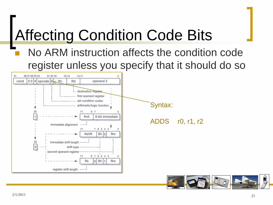
Affecting Condition Code Bits No ARM instruction affects the condition code
register unless you specify that it should do so
2/1/2011 19
Setting “S” instructs the ARM to set/clear the appropriate status register bits based on the results

Affecting Condition Code Bits No ARM instruction affects the condition code
register unless you specify that it should do so
2/1/2011 20
Setting “S” instructs the ARM to set/clear the appropriate status register bits based on the results
If S=0, no status register bits will be affected
Affecting Condition Code Bits No ARM instruction affects the condition code
register unless you specify that it should do so
2/1/2011 21
Syntax:
ADDS r0, r1, r2

Conditional Execution Every instruction can be conditionally executed
2/1/2011 22
With the proper code, an instruction may be executed ONLY under certain conditions (i.e.; if the Z bit is set, or if the N bit is set)
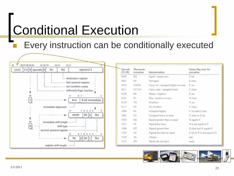
Conditional Execution Every instruction can be conditionally executed
2/1/2011 23

Conditional Execution Every instruction can be conditionally executed
2/1/2011 24
Really!They have one you cannot use!!

Conditional Execution Every instruction can be conditionally executed
2/1/2011 25
Syntax: ADDNE r0, r1, r2

Conditional Execution Every instruction can be conditionally executed
2/1/2011 26
Syntax: ADDNE r0, r1, r2
Add r1 and r2 and place the results in r0 IFthe Z bit = 0 otherwise, skip this instruction

Conditional Execution Every instruction can be conditionally executed
2/1/2011 27
Syntax: ADDNE r0, r1, r2
Of course, you can have it affect the status register bits also:
ADDNES r0, r1, r2

Conditional Execution Example:
2/1/2011 28
CMP r0, #5BEQ BypassADD r1, r1, r0SUB r1, r1, r2
Bypass
Can be replaced by:
CMP r0, #5ADDNE r1, r1, r0SUBNE r1, r1, r2
if (r0 != 5) {r1 = r1 + r0 – r2;
}
Equivalent C:

Multiply Instructions Simple multiply
Immediate operands are not allowed Result register (r0) cannot be the same as the 1st
source register If ‘S’ bit is set (MULS)
V bit is preserved C bit is meaningless
Get a 32 bit result (should be 64) Lower 32 bits are saved Upper 32 bits are ignored
2/1/2011 29
MUL r0, r1, r2 ; r0 := r1 * r2

Multiply Instructions Multiply-Accumulate
Adds the product (r3 * r2) to a running total (r1) Same restrictions
Immediate operands are not allowed Result register (r4) cannot be the same as the 1st
source register If ‘S’ bit is set (MLAS): V bit preserved, C bit
meaningless lower 32 bits
2/1/2011 30
MLA r4, r3, r2, r1 ; r4 := r3 * r2 + r1

Multiply Instructions With all these restrictions in multiply instructions,
it may be easier to add:
2/1/2011 31
ADD r0, r0, r0, LSL #2 ; r0 := r0 * 5

Multiply Instructions With all these restrictions in multiply instructions,
it may be easier to add:
2/1/2011 32
ADD r0, r0, r0, LSL #2 ; r0 := r0 * 5; r0 logic shift left twice = r0 *4; + one more r0 = r0 * 5; put the result in r0
Multiply Instructions With all these restrictions in multiply instructions,
it may be easier to add:
2/1/2011 33
ADD r0, r0, r0, LSL #2 ; r0 := r0 * 5; r0 logic shift left twice = r0 *4; + one more r0 = r0 * 5; put the result in r0
RSB r0, r0, r0, LSL #3 ; r0 := r0 * 7

Multiply Instructions With all these restrictions in multiply instructions,
it may be easier to add:
2/1/2011 34
ADD r0, r0, r0, LSL #2 ; r0 := r0 * 5; r0 logic shift left twice = r0 *4; + one more r0 = r0 * 5; put the result in r0
RSB r0, r0, r0, LSL #3 ; r0 := r0 * 7; RSB is reverse sub ; r0 logic shift left 3 x is r0 * 8; subtract r0: r0 = r0 * 7; put the result in r0

Multiply Instructions With all these restrictions in multiply instructions,
it may be easier to add:
2/1/2011 35
ADD r0, r0, r0, LSL #2 ; r0 := r0 * 5; r0 logic shift left twice = r0 *4; + one more r0 = r0 * 5; put the result in r0
RSB r0, r0, r0, LSL #3 ; r0 := r0 * 7; RSB is reverse sub ; r0 logic shift left 3 x is r0 * 8; subtract r0: r0 = r0 * 7; put the result in r0
If you want r0 * 35 – put the two instructions together

Data Transfer Instructions Three categories:
Single Register Load and Store instructions Multiple Register Load and Store instructions Single Register Swap instructions
ARM data transfer instructions are based on register-indirect addressing (Furber, 2000, pg 56)
2/1/2011 36

Single Register Load/Store Based on register indirect
Uses a value in one register as a memory address Register is called the base register
May include: Base + offset Base + index
2/1/2011 37
LDR r0, [r1] ; r0 := (memoryr1)STR r0, [r1] ; (memoryr1) := data in r0

Single Register Load/Store Example:
2/1/2011 38
r0 = ?r1 = 00001204
LDR r0, [r1] ; r0 := (memoryr1)
What is in r0 after this instruction?
0x00001200 340x00001201 A20x00001202 4E0x00001203 100x00001204 4D0x00001205 660x00001206 310x00001207 640x00001208 870x00001209 AD0x0000120A 5F0x0000120B 3C0x0000120C 90

Single Register Load/Store Example:
2/1/2011 39
r0 = ?r1 = 00001204
LDR r0, [r1] ; r0 := (memoryr1)
What is in r0 after this instruction?
r0 = 4D663164
0x00001200 340x00001201 A20x00001202 4E0x00001203 100x00001204 4D0x00001205 660x00001206 310x00001207 640x00001208 870x00001209 AD0x0000120A 5F0x0000120B 3C0x0000120C 90

Single Register Load/Store Example:
2/1/2011 40
r0 = ?r1 = 00001204
LDR r0, [r1] ; r0 := (memoryr1)
What is in r0 after this instruction?
r0 = 4D663164 if this is big endianr0 = 6431664D if this is little endian
0x00001200 340x00001201 A20x00001202 4E0x00001203 100x00001204 4D0x00001205 660x00001206 310x00001207 640x00001208 870x00001209 AD0x0000120A 5F0x0000120B 3C0x0000120C 90

Base + offset An offset of up to 4 kbytes may be added or
subtracted to the base register:
r1 should remain unchanged *
2/1/2011 41
LDR r0, [r1 + 4] ; r0 := (memoryr1+4)
Auto-Indexing To update the indirect register (r1 in this case)
you may auto-index:
You may also do this by:
These offsets could also be in a register (and so are subject to manipulation
2/1/2011 42
LDR r0, [r1 + 4]! ; r0 := (memoryr1+4); r1 := r1 + 4
LDR r0, [r1], #4 ; r0 := (memoryr1); r1 := r1 + 4
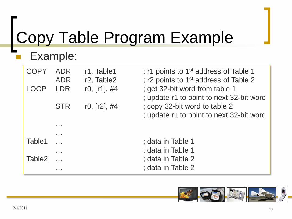
Copy Table Program Example Example:
2/1/2011 43
COPY ADR r1, Table1 ; r1 points to 1st address of Table 1ADR r2, Table2 ; r2 points to 1st address of Table 2
LOOP LDR r0, [r1], #4 ; get 32-bit word from table 1; update r1 to point to next 32-bit word
STR r0, [r2], #4 ; copy 32-bit word to table 2; update r1 to point to next 32-bit word
……
Table1 … ; data in Table 1… ; data in Table 1
Table2 … ; data in Table 2… ; data in Table 2

Copy Table Program Example Equivalent to last example:
2/1/2011 44
COPY ADR r1, Table1 ; r1 points to 1st address of Table 1ADR r2, Table2 ; r2 points to 1st address of Table 2
LOOP LDR r0, [r1]! ; get 32-bit word from table 1; update r1 to point to next 32-bit word
STR r0, [r2]! ; copy 32-bit word to table 2; update r1 to point to next 32-bit word
……
Table1 … ; data in Table 1… ; data in Table 1
Table2 … ; data in Table 2… ; data in Table 2

Single Register Load/Store You may also transfer just one byte of data
Not subject to the 4-byte boundary
Data is in the first 8 bits Other bits are 0s
2/1/2011 45
LDRB r0, [r1] ; r0 := (memoryr1)STRB r0, [r1] ; (memoryr1) := data in r0

Multiple Register Transfers You may also transfer data to multiple registers
at one time
2/1/2011 46
LDMIA r0, {r1, r2, r5} ; r1 := (memoryr0); r2 := (memoryr0+4); r5 := (memoryr0+8)
-- r0 is unchanged
STMIA r0, {r2-r5} ; (memoryr0) := data in r2; (memoryr0+4) := data in r3; (memoryr0+8) := data in r4; (memoryr0+12) := data in r5
-- r0 is unchanged

Multiple Register Transfers You may also transfer data to multiple registers
at one time and auto-index
2/1/2011 47
LDMIA r0!, {r1, r2, r5} ; r1 := (memoryr0); r2 := (memoryr0+4); r5 := (memoryr0+8)
-- r0 is changed to r0 + 8
STMIA r0!, {r2-r5} ; (memoryr0) := data in r2; (memoryr0+4) := data in r3; (memoryr0+8) := data in r4; (memoryr0+12) := data in r5
-- r0 is changed to r0 + 12

Flow Control Flow Control includes all of the conditional
branch instructions
2/1/2011 48
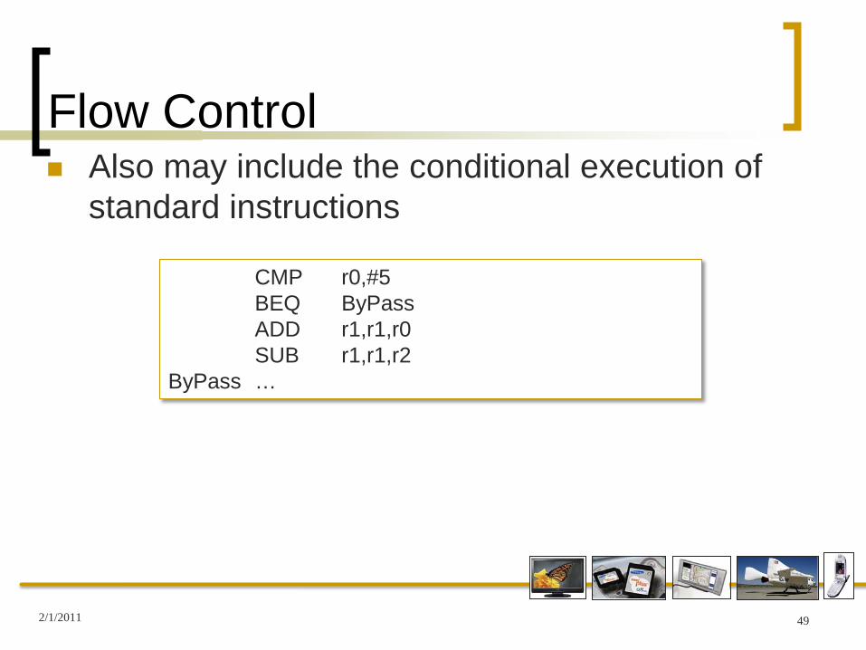
Flow Control Also may include the conditional execution of
standard instructions
2/1/2011 49
CMP r0,#5BEQ ByPassADD r1,r1,r0SUB r1,r1,r2
ByPass …

Flow Control Also may include the conditional execution of
standard instructions
2/1/2011 50
CMP r0,#5BEQ ByPass ; if (r0 != 5) {ADD r1,r1,r0 ; r1 := r1 + r0 – r2;SUB r1,r1,r2 ; }
ByPass …
May be replaced by:CMP r0,#5ADDNE r1,r1,r0SUBNE r1,r1,r2

Flow Control Another example
2/1/2011 51
; if ((a == b) && (c == d)) e++;

Flow Control Another example
2/1/2011 52
; if ((a == b) && (c == d)) e++;
CMP r0,r1CMPEQ r2,r3ADDEQ r4,r4,#1

Flow Control Supervisor Calls
In many ARM systems, supervisor mode is required to perform system level functions
Referred to as privileged Instruction you don’t normally want directly executed in the
standard user mode
The limitations placed on “user mode” vary from system to system On most simple programs, supervisor mode is not
necessary
2/1/2011 53
Flow Control Supervisor Calls
To get into the supervisor mode, it is normal to execute an SWI SWI = Software Interrupt Used to enter supervisor mode
2/1/2011 54

Summary We became familiar with the programmer’s
model of the ARM Byte ordering (Big/Little Endian) Status register bits Registers
We became familiar with several categories of instructions for the ARM
Data processing Data transfer Flow control Conditional execution of instructions
2/1/2011 55