microchip technical training medialb training v4.0 - page...
TRANSCRIPT

MICROCHIP Technical Training
MediaLB Training V4.0 - page 1
This presentation (TM_MediaLB_d22) is based on the MediaLB Specification V4.2.
The file TB0400AN4V2_-_MediaLB_Specification_4v2.pdf is available from Microchip.
To download it, please go to the link below, or contact [email protected].
http://www.microchip.com/pagehandler/en-us/products/automotive/solutions/MediaLB.html?tab=t2
MICROCHIP Technical Training
MediaLB Training V4.0 - page 2

MediaLB is an on-PCB or inter-chip communication bus, specifically designed to standardize a common
hardware interface and software API library. This standardization allows an application or multiple
applications to access the MOST® (Media Oriented Systems Transport) Network data, or to
communicate with other applications, with minimum effort. MediaLB is designed to support all MOST
Networks; thereby, providing a simple migration path between different MOST Network architectures.
MediaLB also supports all MOST network data transport methods: synchronous stream data,
asynchronous packet data, control message data, and isochronous data.
The INIC (Intelligent Network Interface Controller for MOST) is a MediaLB Controller providing a
hardware MediaLB interface and a software API library, which is implemented through the current
firmware of the various INICs. Through this firmware the complete configuration of MediaLB is
accessible.
The MediaLB Controller provides the interface to the MOST Network and is also synchronous to the
MOST Network. This has a positive effect in that the entire MediaLB system is synchronous. If the
MediaLB system looses lock from the MOST network, it will continue to work allowing communication
between different MediaLB devices and the MediaLB Controller, i.e. inside the MOST device.
The MediaLB Controller can communicate with one or several MediaLB devices. MediaLB also
supports the communication between several MediaLB devices without involving the MediaLB
controller.
MediaLB bandwidth is scalable making it adaptable to various applications. The design engineer can
implement a low cost solution with lower data throughput by using a low frame rate. High performance
implementation is available using frame rates of upto 1024Fs for 3-pin MediaLB, and upto 8192Fs for 6-
pin MediaLB interface.
MICROCHIP Technical Training
MediaLB Training V4.0 - page 3
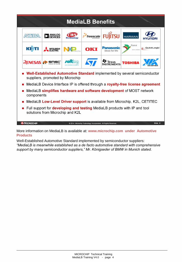
More information on MediaLB is available at: www.microchip.com under Automotive
Products
Well-Established Automotive Standard implemented by semiconductor suppliers:
“MediaLB is meanwhile established as a de facto automotive standard with comprehensive
support by many semiconductor suppliers,” Mr. Königseder of BMW in Munich stated.
MICROCHIP Technical Training
MediaLB Training V4.0 - page 4

MICROCHIP Technical Training
MediaLB Training V4.0 - page 5

MediaLB supports a wide range of configurations offering bandwidth up-to 330 Mbps.
For the high data rates supported by 6-pin MediaLB, the clock rate sent from the controller to devices is
either 1536Fs or 2048Fs, and this clock is internally multiplied within the MediaLB devices to the higher
data rates based on the mode selected.
Fs stands for ‘Frame Sequence’, which can be either 44.1 kHz or 48 kHz in a MOST Network.
Example:
A value of 1024 x Fs for the MediaLB Clock means that the Bit-clock in this particular MediaLB system
is 49.2 MHz in a system running at 48 kHz MOST Frame sequence.
Note:
MediaLB 3-pin can be used in MOST devices running in a MOST25, MOST50 or even in a MOST150
network.
MediaLB 6-pin can be used in MOST devices running in a MOST150 network only, because only the
INIC for MOST150 has a MediaLB 6-pin interface.
MOST devices using different MediaLB speed modes on their PCB (e.g. 256 xFS and 1024xFS) can be
connected and communicate via the same MOST network.
MICROCHIP Technical Training
MediaLB Training V4.0 - page 6
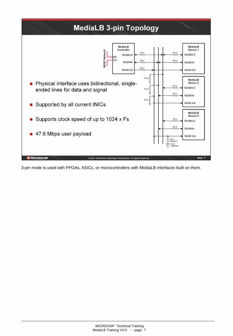
3-pin mode is used with FPGAs, ASICs, or microcontrollers with MediaLB interfaces built on them.
MICROCHIP Technical Training
MediaLB Training V4.0 - page 7
MICROCHIP Technical Training
MediaLB Training V4.0 - page 8

This presentation is based on MediaLB Specification V4.2
The file TB0400AN4V2_-_MediaLB_Specification_4v2.pdf is available from Microchip on request.
MICROCHIP Technical Training
MediaLB Training V4.0 - page 9

The drawing depicts the MediaLB timing diagram highlighting the MLBCLK line.
MICROCHIP Technical Training
MediaLB Training V4.0 - page 10
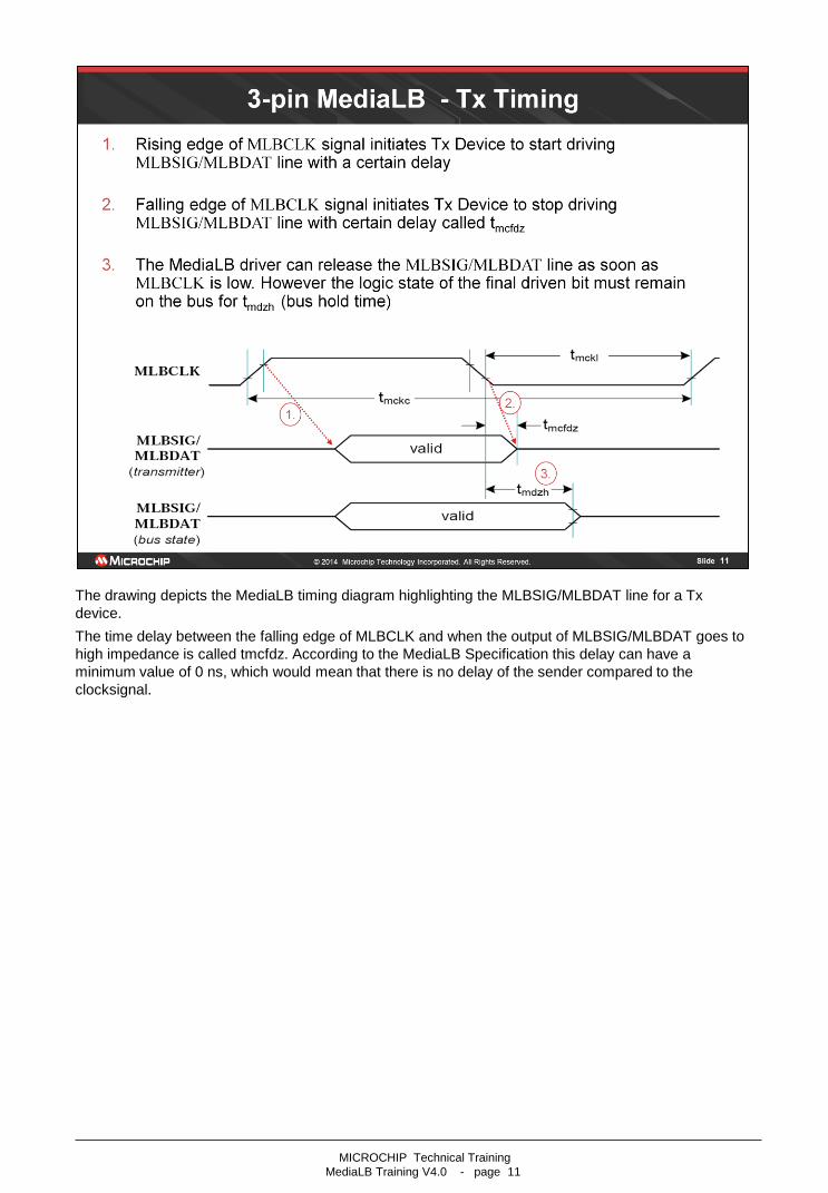
The drawing depicts the MediaLB timing diagram highlighting the MLBSIG/MLBDAT line for a Tx
device.
The time delay between the falling edge of MLBCLK and when the output of MLBSIG/MLBDAT goes to
high impedance is called tmcfdz. According to the MediaLB Specification this delay can have a
minimum value of 0 ns, which would mean that there is no delay of the sender compared to the
clocksignal.
MICROCHIP Technical Training
MediaLB Training V4.0 - page 11

The drawing depicts the MediaLB timing diagram highlighting the MLBSIG/MLBDAT line for an Rx
devices.
Before the Rx Device is able to capture data the corresponding signal has to be stable for a specific
time called tdsmcf (Data or Signal on MediaLB valid befor Clock Falling)
This time period has to be long enough so that the RX hardware (flip flop) is able to capture the correct
data.
After data has been captured by the RX device the signal on MLBSIG/MLBDAT must still be valid for a
specific time.
MICROCHIP Technical Training
MediaLB Training V4.0 - page 12

MICROCHIP Technical Training
MediaLB Training V4.0 - page 13

This termination has been proven in the lab for 1024Fs. For slower clock rates, the series termination
may not be needed.
Termination:
All lines require pull-down resistors to keep signal in a known state when not being driven. MLBSIG,
MLBDAT pull-downs are weak so a logic ‘1’ on the bus isn’t pulled low before devices can latch data.
MLBCLK is pulled down, so the clock is in a known state during startup.
AC termination recommended on MLBCLK at farthest device from INIC.
Series resistors limit rise and fall times, reducing EMI.
Routing:
Trace lengths are matched to minimize clock to data skew.
The values for the resistors and capacitors are only a recommendation.
MICROCHIP Technical Training
MediaLB Training V4.0 - page 14

MICROCHIP Technical Training
MediaLB Training V4.0 - page 15

MICROCHIP Technical Training
MediaLB Training V4.0 - page 16

MICROCHIP Technical Training
MediaLB Training V4.0 - page 17
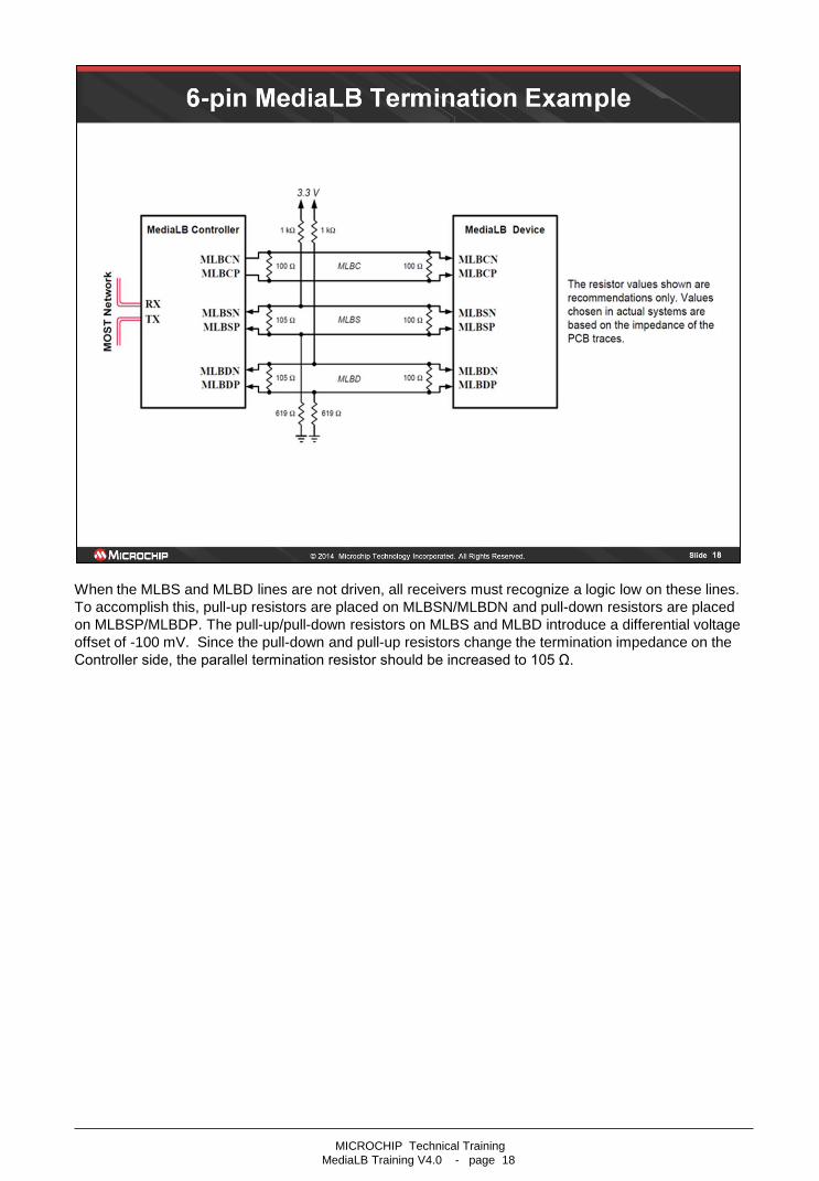
When the MLBS and MLBD lines are not driven, all receivers must recognize a logic low on these lines.
To accomplish this, pull-up resistors are placed on MLBSN/MLBDN and pull-down resistors are placed
on MLBSP/MLBDP. The pull-up/pull-down resistors on MLBS and MLBD introduce a differential voltage
offset of -100 mV. Since the pull-down and pull-up resistors change the termination impedance on the
Controller side, the parallel termination resistor should be increased to 105 Ω.
MICROCHIP Technical Training
MediaLB Training V4.0 - page 18

MICROCHIP Technical Training
MediaLB Training V4.0 - page 19

This presentation is based on MediaLB Specification V4.2
The file TB0400AN4V2_-_MediaLB_Specification_4v2.pdf is available from Microchip on request.
MICROCHIP Technical Training
MediaLB Training V4.0 - page 20

MediaLB transmits data using so-called MediaLB frames which are synchronized to the MOST frames
by the INIC. This slide shows a MediaLB Clock speed (MLBC) of 256xFs and its corresponding
MediaLB Frame.
For 512xFs, 1024xFs, and also for higher speeds of MLBC just the total number of Physical Channels
per MediaLB frame increases, hence the available bandwidth.
For details see the following slides.
MediaLB Devices are synchronously slaved to the MediaLB Controller through the MLBC. Since the
controller is synchronized to the MOST Network, the MLBC signal provides Network synchronization to
all MediaLB Devices. Once the controller starts up MLBC, all MediaLB Devices must synchronize to the
MediaLB frame before communication can commence. When not frame-locked, devices must search
for the FRAMESYNC pattern, which defines the byte boundary, the physical channel boundary, and
determines the start of the MediaLB frame. Even when a device is frame-locked, it shall check every
following frame to validate that it remains frame-locked. While frame-locked, the device can access
MediaLB according to the rules of the MediaLB protocol.
All MediaLB Devices must use the following synchronization rules:
• If FRAMESYNC is detected for three consecutive frames the MediaLB Device shall declare lock and
resume operation.
• If FRAMESYNC is not detected for two consecutive frames the MediaLB Device shall declare
Unlock and stop driving MLBS and MLBD.
• If FRAMESYNC is detected unexpectedly the MediaLB Device shall not synchronize to the
unexpected FRAMESYNC as long as FRAMESYNC is still detected at the expected time.
MICROCHIP Technical Training
MediaLB Training V4.0 - page 21

The MediaLB data structure consists of a ChannelAddress, a Command, an RxStatus, and a quadlet of
data (Physical Channel).
The MLBS line is a multiplexed signal which carries ChannelAddresses generated by the MediaLB
Controller, as well as Command and RxStatus bytes from MediaLB Devices. Each ChannelAddress
indicates which Device can transmit data and which Device (or Devices) can receive data on a
particular logical channel.
One physical channel later than the ChannelAddress has been sent on MLBS, the transmitting
MediaLB Device associated with that ChannelAddress outputs a command byte (Command) on MLBS
and respective data (Data) on MLBD, concurrently. The Command byte contains information about the
4-byte data payload simultaneously being transmitted.
The MediaLB Device receiving the data shifts out a status byte (RxStatus) on MLBS after the
transmitting Device sends the Command byte. This status response can indicate that the Device is
ready to receive the data, or that the receiving Device is busy (e.g. cannot receive the data at present).
Since synchronous data is sent in a broadcast fashion, Devices receiving synchronous data can never
return a busy status response. In this situation, the RxStatus byte must not be actively driven onto the
MLBS line by Devices receiving synchronous data.
MICROCHIP Technical Training
MediaLB Training V4.0 - page 22

The ChannelAddress is made up of 16 bits and can be defined in the range of 0002h upto 007Eh. All
odd ChannelAddresses are reserved, providing a total of 63 available ChannelAddresses.
The ChannelAddress 0x0000 is defined as the BusIdle state, which indicates that the corresponding
physical channel is not assigned and not used by any device.
The ChannelAddress 01FEh defines the FRAMESYNC and the SystemChannel.
All odd ChannelAddresses are reserved. Therefore, the LSB of a valid ChannelAddress is always zero.
In combination with the pull-down resistor on the MLBS line this ensures:
• BusIdle for un-assigned channels
• no unexpected FRAMESYNC present on the bus
MICROCHIP Technical Training
MediaLB Training V4.0 - page 23

Each logical channel type provides special commands to signal to the receiving device that a message
starts, continues, or ends.
The Least Significant Bit (LSB) of every ChannelAddress, Command, and RxStatus is low (zero) to
support BusIdle for an un-assigned channel and ensures proper detection of FRAMESYNC. The
advantage of the signal “zeroed“ at the LSB is that the task of the pull down resistor is only to hold the
signal at zero.
The System Channel, which is loacted in the 1st physical channel of the MediaLB Frame, is reserved for
System Commands, but they are optional:
• Sent on MLBS by the MediaLB-Controller to one or more Devices.
• Used to signal special system events (e.g. MOST_Lock, MOST_Unlock, …).
• Used for system initialization.
• System Commands are not supported by current INICs.
MICROCHIP Technical Training
MediaLB Training V4.0 - page 24

MICROCHIP Technical Training
MediaLB Training V4.0 - page 25

The current RxStatus state bytes indicate the status of the Rx Device in the current physical channel,
whereas the feedback RxStatus are responses to the previous Command in the logical channel. For
normal responses, only the ReceiverProtocolError is a feedback RxStatus byte.
In addition to Normal RxStatus the System Channel (first physical channel) can be used to respond with
System RxStatus (optional) to System Commands:
• Sent on MLBS by the Rx Device
• Sent as feedback to MlbScan System Command
MICROCHIP Technical Training
MediaLB Training V4.0 - page 26

MICROCHIP Technical Training
MediaLB Training V4.0 - page 27

Multiple Physical Channels can be grouped logically together, to make up one (big) Logical Channel.
Logical Channels are defined by a unique ChannelAddress.
The Rx device and the Tx device both use the same ChannelAddress, which may be defined by
firmware or switches. Multi-quadlet Logical Channels are not guaranteed to be consecutive. In addition,
Physical Channels assignments for Logical Channels are arbitrary.
MICROCHIP Technical Training
MediaLB Training V4.0 - page 28
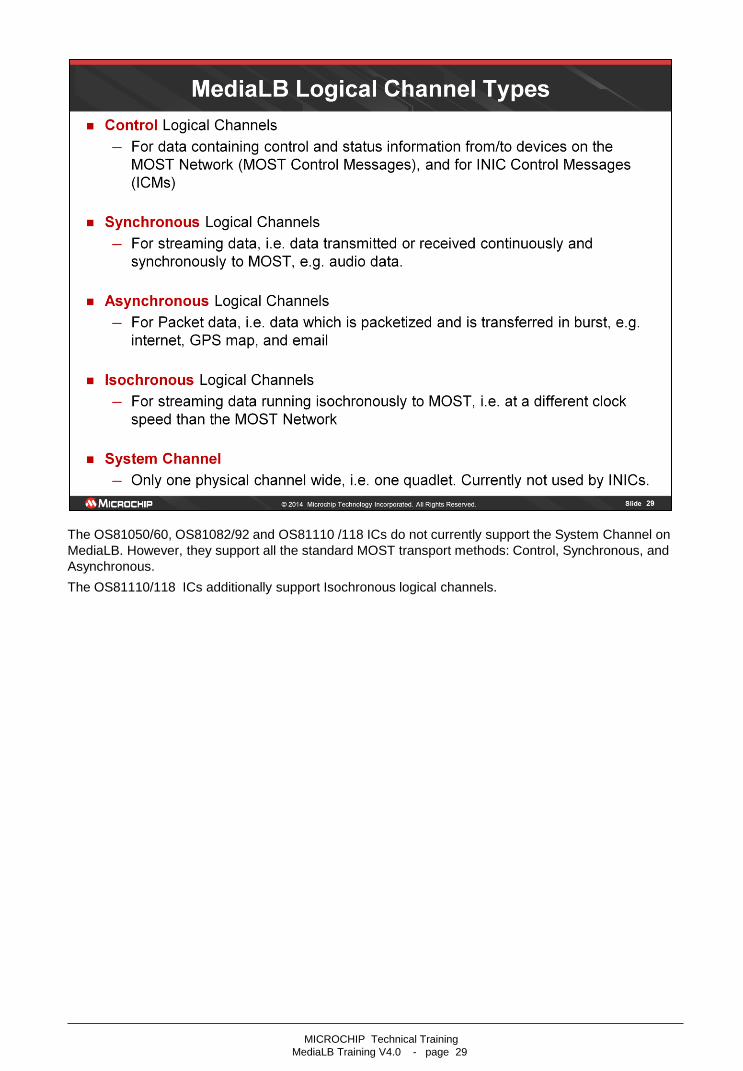
The OS81050/60, OS81082/92 and OS81110 /118 ICs do not currently support the System Channel on
MediaLB. However, they support all the standard MOST transport methods: Control, Synchronous, and
Asynchronous.
The OS81110/118 ICs additionally support Isochronous logical channels.
MICROCHIP Technical Training
MediaLB Training V4.0 - page 29

This example illustrates 4 unidirectional logical channels, where each communication path / direction
needs a separate logical channel. For bidirectional communication two Logical Channels on MediaLB
are required.
If INIC starts up with MediaLB port per default, two logical channels are automatically defined on
ChannelAddress 0x0002 and 0x0004. INIC uses ChannelAddress 0x0002 to transmit and
ChannelAddress 0x0004 to receive Control data. These ChannelAddresses provide communication
between the MediaLB Controller (INIC) and the MediaLB Device (EHC). The EHC can use these
Control channels to configure the MediaLB bus according to the application’s needs.
The Logical Channel 0x000C addresses the MediaLB Controller, the MediaLB Device 1 and MediaLB
Device 2. The MediaLB Controller can, at the same time, send synchronous data to MediaLB devices 1
and 2. However this logical channel 0x000C cannot be used to send synchronous data from MediaLB
Device 1 or 2 to the MediaLB Controller.
To send synchronous data from MediaLB Device 1 to MediaLB Device 2, Logical channel 0x000E is
used.
The slide also shows the appropriate INIC commands which must be sent from the application on the
EHC to the INIC to setup the logical channels on MediaLB as discussed in the example above.
MICROCHIP Technical Training
MediaLB Training V4.0 - page 30

This example illustrates which device is driving the MediaLB signal and data lines and is related to a MediaLB
speed of 256Fs, thus 8 physical channels are available. One quadlet (PC0) is always used for the FRAMESYNC
pattern and System Channel. The remaining 7 quadlets are grouped into 4 logical channels. Physical Channel
PC1 is assigned to logical channel A (0x0002) and represents the Tx Control channel from the MediaLB
Controller. The Physical Channel PC2 is assigned to Logical Channel B (0x0004) and represents the Rx Control
channel of the MediaLB Controller.
The Physical Channels PC3, PC5 and PC6 are grouped together to build-up the Logical Channel C (0x000C). This
channel represents the Tx synchronous channel from the MediaLB Controller. The remaining two pyhsical
channels PC4 and PC7 are grouped to Logical Channel E (0x000E). This channel can be used to transport
synchronous data from MediaLB device 1 to MediaLB device 2.
PC0: System Channel is unused, but bandwidth reserved. However the Controller sends out the next
ChannelAddress using Bytes 3 and 4 of PC0. This Address will be allowed to transport data in PC2.
PC1: Controller sends out a command on MLBS and at the same time it sends the data on the MLBD line. In the
second Byte of PC1 on MLBS, the receiving MediaLB device transmits the RxStatus. The Rx Status shows if the
receiving MediaLB device is ready to receive data. In case there has been a transmission error, the receiving
Device cannot signal this condition in the current Physical Channel, i.e. PC1. Instead, the receiver will use the next
PC which belongs to the same ChannelAddress to signal errors using the RxStatus Byte (e.g. a Protocol Error).
Finally the Controller sends out the next ChannelAddress using Bytes 3 and 4 of PC1 on MLBS. This Address will
be allowed to transport data in PC3 on MLBD.
PC2: The ChannelAddress (0x0002) which has been sent 2 quadlets before, i.e. in PC0, has determined that
MediaLB Device 1 is allowed to send data in PC2. Thus the EHC (device 1) starts sending a Command on the 1st
Byte of this PC, and at the same time sends data on MLBD. Now the Controller (INIC) receives the data and
sends an RxStatus in the second Byte of PC2 on MLBS. Finally the Controller sends out the next ChannelAddress
(0x000E) using Bytes 3 and 4 of PC2 on MLBS. The device at this Address will be allowed to transport data in
PC4 on MLBD.
The flow for the other PCs is similar.
MICROCHIP Technical Training
MediaLB Training V4.0 - page 31

The MediaLB Controller manages the System Channel and indicates the boundaries of the MediaLB
frames by cyclically sending out the unique FRAMESYNC signal on the MLBS line. Also the MediaLB
Controller generates SystemCommands and outputs these commands on the MLBS line. The MediaLB
Controller also manages the arbitration for all the physical channels on the MediaLB and grants
bandwidth for all MediaLB devices by outputting the ChannelAddresses on the MLBS line. If a bus error
is detected, the MediaLB Controller may manage error concealment functions.
MICROCHIP Technical Training
MediaLB Training V4.0 - page 32
Each MediaLB Device provides a MediaLB lock detection. Once the Controller starts up the MLBC, all
MediaLB Devices must be synchronized to the MediaLB frame before communication can start. When
not frame-locked, devices must search for the FRAMESYNC pattern, which defines the byte boundary,
the physical channel boundary, and determines the start of the MediaLB frame. Even when a device is
frame-locked, it shall check every frame continuing to validate that it remains frame-locked.
A MediaLB Device is able to transmit to, and receive data from MediaLB. A MediaLB Device outputs
Commands and data if the MediaLB Device is transmitting for the corresponding ChannelAddress (Tx
Device). It outputs RxStatus and receives Data if the MediaLB Device is receiving for the
ChannelAddress (Rx Device).
MICROCHIP Technical Training
MediaLB Training V4.0 - page 33

This presentation is based on MediaLB Specification V4.2
The file TB0400AN4V2_-_MediaLB_Specification_4v2.pdf is available from Microchip on request.
MICROCHIP Technical Training
MediaLB Training V4.0 - page 34
MICROCHIP Technical Training
MediaLB Training V4.0 - page 35
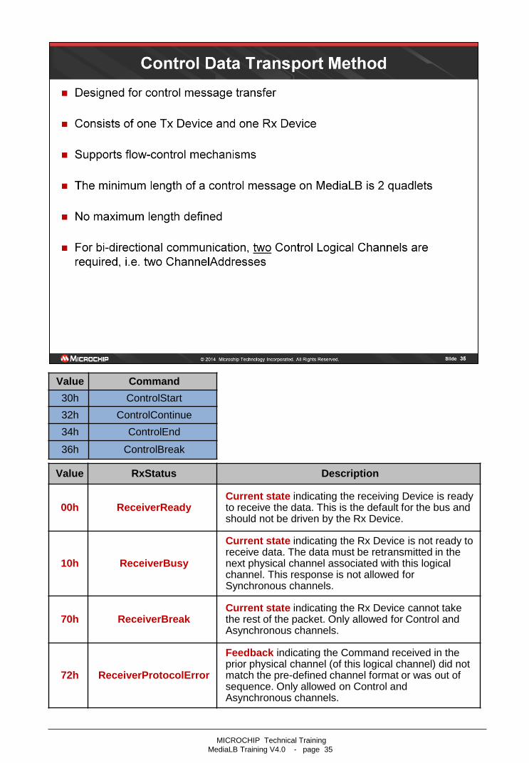
Value Command
30h ControlStart
32h ControlContinue
34h ControlEnd
36h ControlBreak
Value RxStatus Description
00h ReceiverReady Current state indicating the receiving Device is ready to receive the data. This is the default for the bus and should not be driven by the Rx Device.
10h ReceiverBusy
Current state indicating the Rx Device is not ready to receive data. The data must be retransmitted in the next physical channel associated with this logical channel. This response is not allowed for Synchronous channels.
70h ReceiverBreak Current state indicating the Rx Device cannot take the rest of the packet. Only allowed for Control and Asynchronous channels.
72h ReceiverProtocolError
Feedback indicating the Command received in the prior physical channel (of this logical channel) did not match the pre-defined channel format or was out of sequence. Only allowed on Control and Asynchronous channels.
MICROCHIP Technical Training
MediaLB Training V4.0 - page 36

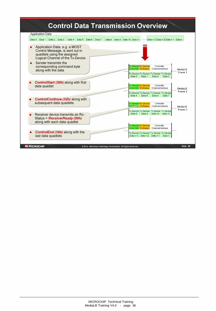
Flow control for Control data is realized by the RxStatus responses of the Rx Device:
ReceiverReady (00h)
• Flow control mechanism for Rx Device to communicate to Tx Device when it is ready to receive
data.
ReceiverBusy (10h)
• Flow control mechanism for Rx Device to communicate to Tx Device when it is not ready to receive
data.
• Rx Device rejects the quadlet of Command and Data.
• Tx Device must re-transmit the quadlet of Command and Data in the next quadlet in the logical
channel.
Both are Current Rx Status responses, i.e. sent in the same quadlet on MediaLB signal line (MLBS) as
the corresponding data quadlet is sent on the MediaLB data line (MLBD).
MICROCHIP Technical Training
MediaLB Training V4.0 - page 37

MICROCHIP Technical Training
MediaLB Training V4.0 - page 38
If the Tx Device does not have any data to be sent in its assigned Logical Channel, it will signalize this
condition by sending the Command 0x00.
The Rx Device will just respond as usual, i.e. sending an RxStatus 0x00.

This slide shows the situation where the Tx Device wants to abort the transmission of a control
message by sending the MediaLB Command ControlBreak (36h):
• Tx Device marks the break of the current packet.
• Rx Device discards all data received for the current packet.
MICROCHIP Technical Training
MediaLB Training V4.0 - page 39
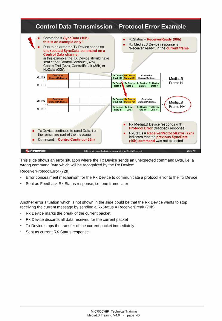
This slide shows an error situation where the Tx Device sends an unexpected command Byte, i.e. a
wrong command Byte which will be recognized by the Rx Device:
ReceiverProtocolError (72h)
• Error concealment mechanism for the Rx Device to communicate a protocol error to the Tx Device
• Sent as Feedback Rx Status response, i.e. one frame later
Another error situation which is not shown in the slide could be that the Rx Device wants to stop
receiving the current message by sending a RxStatus = ReceiverBreak (70h)
• Rx Device marks the break of the current packet
• Rx Device discards all data received for the current packet
• Tx Device stops the transfer of the current packet immediately
• Sent as current RX Status response
MICROCHIP Technical Training
MediaLB Training V4.0 - page 40

MICROCHIP Technical Training
MediaLB Training V4.0 - page 41
Value RxStatus Description
00h ReceiverReady Current state indicating the receiving Device is ready to receive the data. This is the default for the bus and should not be driven by the Rx Device.
10h ReceiverBusy
Current state indicating the Rx Device is not ready to receive data. The data must be retransmitted in the next physical channel associated with this logical channel. This response is not allowed for Synchronous channels.
70h ReceiverBreak Current state indicating the Rx Device cannot take the rest of the packet. Only allowed for Control and Asynchronous channels.
72h ReceiverProtocolError
Feedback indicating the Command received in the prior physical channel (of this logical channel) did not match the pre-defined channel format or was out of sequence. Only allowed on Control and Asynchronous channels.
Value Command
20h AsyncStart
22h AsyncContinue
24h AsyncEnd
26h AsyncBreak
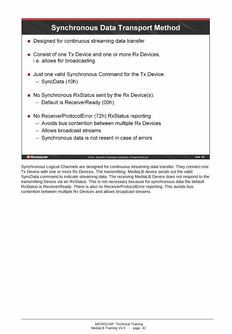
Synchronous Logical Channels are designed for continuous streaming data transfer. They connect one
Tx Device with one or more Rx Devices. The transmitting MediaLB device sends out the valid
SyncData command to indicate streaming data. The receiving MediaLB Device does not respond to the
transmitting Device via an RxStatus. This is not necessary because for synchronous data the default
RxStatus is ReceiverReady. There is also no ReceiverProtocolError reporting. This avoids bus
contention between multiple Rx Devices and allows broadcast streams.
MICROCHIP Technical Training
MediaLB Training V4.0 - page 42

MICROCHIP Technical Training
MediaLB Training V4.0 - page 43

MICROCHIP Technical Training
MediaLB Training V4.0 - page 44

The picture illustrates the different available Isochronous data formats. After the Controller has granted
bandwidth on MediaLB, the transmitting MediaLB device sends its command that includes the
information that the data on the MLBD line are Isochronous data. The ReceiverReady indicates that the
receiving device is ready to receive data.
The different MLBD lines show the valid data related to different Isochronous Commands. On the first
MLBD line all 4 bytes of the physical channel contain valid data. The MLBD line below shows that only
the first 3 bytes of the physical channel contain valid data. The next 2 lines can be interpreted
accordingly.
On the last MLBD line, no bytes of the physical channel contains valid data.
MICROCHIP Technical Training
MediaLB Training V4.0 - page 45

MICROCHIP Technical Training
MediaLB Training V4.0 - page 46