michelson interferometry and measurement of the sodium
TRANSCRIPT
Michelson Interferometry and Measurement of the Sodium Doublet Splitting
PHYS 3330: Experiments in OpticsDepartment of Physics and Astronomy,
University of Georgia, Athens, Georgia 30602
(Dated: Revised October 2011)
In this lab we will use a Michelson interferometer to measure a the small difference in wavelengthbetween two closely spaced spectral lines of a Sodium lamp.
I. INTRODUCTION TO MICHELSONINTERFEROMETERY
In the Michelson interferometer, an incident beam oflight falls on a beam splitter which reflects roughly half ofthe incident light amplitude. Reflected and transmittedbeams follow different paths, are reflected, and recom-bined to producing an interference pattern. The struc-ture of the interference pattern depends upon differencesin the length and alignment of the two arms of the inter-ferometer, and also upon the surface smoothness of theoptical components. One can make quantitative mea-surements of the interference pattern for the accuratecomparison of wavelengths, to measure the refractive in-dex of unknown substances, and measure the quality ofoptical components. The LIGO gravity wave detector isa Michelson interferometer with 2.5 mile long arms.
You will need to complete some background readingbefore your first meeting for this lab. Please carefullystudy the following sections of the “Newport Projects inOptics” document (found in the “Reference Materials”section of the course website): 0.4 “Interference” Also,the excerpt from Melissinos’ “Experiments in ModernPhysics,” included as an appendix to this manual. Fi-nally read section 8.1 of your textbook “Physics of Lightand Optics,” by Peatross and Ware. Your pre-lab quizcover concepts presented in these materials AND in thebody of this write-up. Don’t worry about memorizingequations – the quiz should be elementary IF you readthese materials carefully. Please note that “taking aquick look at” these materials 5 minutes before lab beginswill likely NOT be adequate to do well on the quiz.
The optical circuit of a Michelson interferometer isshown schematically in Figs. 2 and 3. Light from a sourceS passes through a ground glass plate DB (optional) andstrikes the beam splitter P. The beam splitter P is a par-tially silvered mirror (50% reflecting). Half of the in-cident light amplitude toward mirror M1 and transmitshalf of the incident amplitude toward mirror M2. A mi-crometer adjuster screw is attached to the movable mirrorM1, permitting it to be moved toward or away from thebeam splitter in small, precise steps. The two mirrors,beam splitters, and compensating glass are flat to abouta 1/4 of an optical wavelength. The compensating glass,CG, of identical composition and thickness to the beamsplitter, is included so that each of the two beams (pathsP-M1-P-O and P-M2-P-O in Figure 3) passes through the
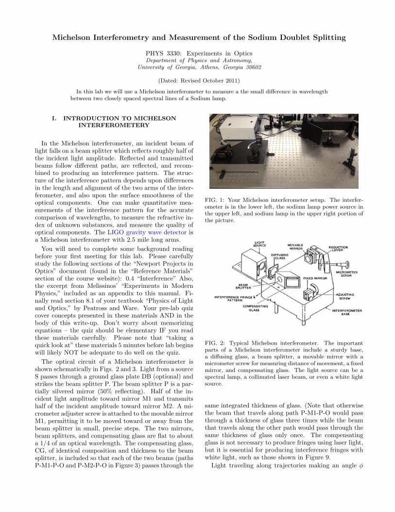
FIG. 1: Your Michelson interferometer setup. The interfer-ometer is in the lower left, the sodium lamp power source inthe upper left, and sodium lamp in the upper right portion ofthe picture.
FIG. 2: Typical Michelson interferometer. The importantparts of a Michelson interferometer include a sturdy base,a diffusing glass, a beam splitter, a movable mirror with amicrometer screw for measuring distance of movement, a fixedmirror, and compensating glass. The light source can be aspectral lamp, a collimated laser beam, or even a white lightsource.
same integrated thickness of glass. (Note that otherwisethe beam that travels along path P-M1-P-O would passthrough a thickness of glass three times while the beamthat travels along the other path would pass through thesame thickness of glass only once. The compensatingglass is not necessary to produce fringes using laser light,but it is essential for producing interference fringes withwhite light, such as those shown in Figure 9.
Light traveling along trajectories making an angle φ

2
FIG. 3: Optical arrangement and light path in Michelson in-terferometer
FIG. 4: Condition for interference
with respect to the optic axis accumulate a path lengthdifference of 2d cos θ between the arms. When this differ-ence is an integer number m = 0, 1, 2... of wavelengths,destructive interference occurs (dark fringes).
mλ = 2d cos θ, m = 1, 2, 3.... (1)
where m is the “order” of the interference. Note thatthe beam in one arm undergoes an additional externalreflection, and thus incurs one additional π phase shift,relative to the beam in the other arm, which is why theabove condition produces a dark, rather than a bright,fringe.
If the two mirrors M1 and M2 are not aligned preciselyperpendicular to one another the path difference will de-pend on the particular region of mirror M1 (and the cor-responding region of M2) which we are observing fromthe position O. The field of view, then, seen by lookingat mirror M1 from position O will be made up of a seriesof alternately bright and dark fringes, nearly straight andparallel, as shown in Figure 5. If the path difference isnear zero, the fringes will be broad and widely spaced inthe field of view; if the path difference is on the orderof 40 or 50 wavelengths the fringes will be narrow andclosely spaced, so much so that they may be unresolv-able by the naked eye. Such fringes are shown in Figure5.
If the two mirrors are precisely aligned exactly parallelto one another, a “bulls-eye” fringe pattern will be seen
FIG. 5: HeNe fringes in a Michelson interferometer from thislab. Photograph taking by your instructor with an iPhone.
FIG. 6: Circular fringes (equal inclination) seen in Michelsoninterferometer
by the observer situated at point “O” in Fig. 3, consisingof a series of concentric rings. Each ring corresponds to adifferent angle φ, as illustrated in Figure 6. In this case,when M1 is translated a distance δz along the optic axis,the number of fringes N that will appear (or disappear)at the center of the bulls-eye pattern is:
N = 2 δz/λ
Thus, if you can measure the displacement of M1 whichcauses a known number of fringes to to appear (or disap-pear) from the center of the pattern, an unknown wave-length can be measured. Conversely, you can use a knownwavelength to calibrate the micrometer screw; i.e., con-vert microns of travel of the screw to microns of travel ofthe mirror (which are not necessarily equal!).
II. ALIGNMENT OF THE INTERFEROMETERUSING A LASER
1. Place and orient your steering mirror to direct the ex-pended beam from a HeNe laser into the the inputport of the interferometer.

3
2. Observe three discs of light emerging from the outputside. Two of the copies will lie almost on top of eachother, but the third will likely be far to the side (oreven absent), if the mirror M2 is misaligned. M2is equipped with two screws on the back side thattilt the plane of the mirror. A slight adjustmentof the mirror tilt screws will cause one of the threeimages to move. You can achieve the proper align-ment of the mirrors by using the screws to super-imposing the (movable) image onto the rightmostof the two stationary images. You will see inter-ference fringes appear, though initially they maybe very finely space. As you adjust M2 you mustmomentarily STOP turning the screws to look forfringes; you will not see fringes if you are turningthe screws even if the mirrors are perfectly aligned,as the movement of the mirror blurs the pattern.
4. It turns out there are two orientations of the M2which produce fringes with a HeNe laser in yourinterferometer. It is important for later stages ofthis lab that you now pick the correct orientation.To do this you must carefully observe the outputand compare to Figure 7. In the wrong case, thestrong fringes die out abruptly on the left side of thedisc, when looking at a ground glass plate installedon the output port. In the correct case the strongfringes extend all the way to the left edge of thepattern. The difference is subtle.
5. While observing the fringes, carefully adjust bothscrews on mirror M2 so that the fringes take a cir-cular “bulls eye” pattern. See Figure 8 for guid-ance.
III. CALIBRATING THE MICROMETERSCREW USING A HENE LASER AS A
WAVELENGTH REFERENCE.
M1 can be translated without disturbing the alignmentof the interferometer. Each tick on the thimble of themicrometer adjuster of M1 corresponds to 1 micron ofmovement of the spindle. One complete revolution of thethimble advances the the spindle through 50 microns,and moves the edge of the thimble across the distance ofone tick-mark on the barrel. Thus, 10 ticks on the barrelis 5mm of movement of the spindle. Make SURE youare clear on how to read the scales on the the microme-ter adjuster before you start taking calibration measure-ments. (See http://en.wikipedia.org/wiki/File:Micrometer_caliper_parts_0001.png if you need apicture.)
1. Set the micrometer screw to approximately 5 mm.
2. Turn the micrometer screw a quarter-turn in thedirection of smaller reading. This is done toavoid backlash since all readings will be taken withthe screw moving in the same direction (towards
FIG. 7: The right (upper) and wrong (lower) appearance ofthe fringes. In the wrong case, the strong fringes die outabruptly on the left side of the disc, here demarcated withthe blue dashed line. In the right case, the strong fringes goall the way to the left edge. The difference is more obviouswhen viewed in person.
smaller readings). Record the reading of the mi-crometer.
3. Count the number of fringes that pass through thecenter of the field of view as the micrometer screw isturned slowly in the direction of decreasing reading.After counting 10 fringes, record the micrometerreading again. When you stop turning the screwat the end of 10 fringes, be very careful to NOTaccidentally slip a fringe while you are recordingthe micrometer reading.
4. Continue this process for 20 groups of 10 fringes.You will find that this procedure requires a cer-

4
FIG. 8: Successive fields of view in interferometer alignment
tain amount of technique (and patience), since theslightest movement of the screw will gain or lose afringe.
IV. ANALYSIS
Enter these points into an Excel spreadsheet, exportas CSV, import the data to python, and perform a fit ofthe data to a linear model. Consider carefully what freeparameters you want to include in your model. Don’tworry about including error bars in this fit. You knowthat each group of 10 fringes actually moves the mirror by5 wavelengths of the HeNe laser. Plot the actual mirrordisplacement vs reading of the micrometer. Fit this datato a straight line. The slope of the line is the calibrationconstant K that you are seeking
K =microns of actual mirror travel
microns of travel of the screw threads.(2)
The uncertainty in the slope as reported by the fittingroutine will be a useful estimate of your uncertainty inthe calibration procedure, and you will use this informa-tion to estimate a systematic uncertainty in your sodiumwavelength measurements of the next section.
V. MEASUREMENT OF CLOSELY SPACEDSPECTRAL LINES VIA MICHELSON
INTERFEROMETERY.
In the next part of the lab you will use your calibratedMichelson interferometer to measure a small differencein wavelength between two closely spaced spectral linesof a sodium lamp. The 589nm “yellow” line of sodiumactually consists of two distinct lines, separated by a fewtenths of a nanometer. When a sodium lamp is used as asource for a Michelson interferometer, each line will pro-duce its own set of fringes with a slightly shifted patternrelative to the other. At certain positions of mirror M1the two sets of fringes coincide (bright regions overlap-ping bright regions), and the total intensity pattern ob-served is a bulls-eye pattern of moderately high contrast(a “sharpening coincidence”). When the M1 is moved,the two sets of fringes evolve slightly differently, and atsome setting will anti-coincide (bright regions overlap-ping dark regions) so that a total intensity pattern dis-plays no fringes (a “wash-out anticoincidence”). We can
use the periodicity of the wash-out phenomenon to mea-sure the sodium line spacing. The theory is describednext.
The two spectral lines whose difference is to be mea-sured are at wavelengths λa, λb. Let δd be the pathlength difference between the two interferometer arms atsome sharpening coincidence. At this coincidence eachset of fringes satisfies a dark fringe criterion for the cen-tral fringe of each bullseye pattern (Equation (1) withθ = 0.
maλa = 2 δd (3)
mbλb = 2 δd (4)
for orders ma and mb which, as integers, must be relatedby
mb = ma +M, (5)
where M is the “order” of the coincidence, or its numberof sharpening coincidences which would have been ob-served if one had started observing from the white lightcondition δd = 0, in which case both interference pat-terns would have had dark central fringes, as there wouldbe no path length difference for either (any!) wavelength.Substituting (2) and (3) into (4) we have:
2 δd/λb = 2 δd/λa +M (6)
or
δd =λaλb2∆λ
M ≈ λ̄2
2∆λM (7)
where λ̄ is the mean wavelength of the two closely spacedlines. Thus, if we measure the mirror position for severalsharpening coincidence orders M,M + 1,M + 2, ... theslope of a linear fit to the data will give us ∆λ. Notethat this is true EVEN if we are off in our reckoning ofthe absolute order M by some an unknown integer X,as the slope we infer from the linear fit to the data is(of course) independent of arbitrary translations of thehorizontal axis M 7→ M + X Therefore it is not criticalto begin the measurement at the white light condition,although it does help to make the sharpening coincidencemore obvious. Also note that the same equations applyfor “wash-outs”, which are typically easier to identify. Inthis lab you will look for wash-outs.
VI. PROCEDURE
1. Turn on the sodium lamp and wait at least 5 minutesfor the light to reach full intensity.
2. Direct the light from the lamp into the interferometerusing the steering mirror.
3. Position a ground glass diffuser at the output port.

5
4. Spin the micrometer screw to nearly its maximum-reading.
5. If you have already achieved fringes with the HeNelaser you should immediately see fringes. If youdo not see fringes it is possible that you have (un-luckily) landed on a wash-out — try spinning themicrometer screw a turn or two. If you still haveno fringes, put the HeNe light back into the in-terferometer to check to see if something has beenbumped.
6. Use the same fringe counting procedure you did forthe HeNe calibration to measure the (mean) wave-length of the (two) sodium D-line(s). For this cal-culation, utilize the micrometer screw calibrationyou measired earlier with the HeNe laser.
Now you will measure the Sodium D-Line doublet split-ting
7. Spin the micrometer screw to nearly its maximum-reading.
8. Turn the micrometer toward smaller readings untilyou see the first sharpening event. Record the mi-crometer position.
9. Continue turing the micrometer toward smallerreadings and record its value for every subsequentwashout you see. It is ok, and indeed recom-mended, to scan back and forth across a washoutposition to determine its location, but remember toalways “finish up” your screw turning by slightlyadvancing the screw in the direction of smallerreading BEFORE recording its value. (This is es-sential to eliminate errors due to backlash in thescrew threads.) Estimate an uncertainty in deter-mining the location of each washout. Be sure todescribe the procedure for making this uncertaintyestimate in your manuscript.
8. Continue recording the positions of washouts untilyou run reach the minimum reading of the microm-eter screw.
VII. ANALYSIS
Use these data, along with your measurement of meanwavelength, and Eq. (5), to determine the sodium D-linesplitting. Propagate all your uncertainties, including thesystematic uncertainty in the micrometer screw calibra-tion, to get a total uncertainty in your D-line splittingmeasurement.
VIII. EXTRA CREDIT – WHITE LIGHTFRINGES
Now you will adjust the interferometer to the “whitelight position,” when the two arms are exactly equal inlength. Tilt your work lamp down so that you can seethe lightbulb when you look into the output of the inter-ferometer. Put a ground glass diffuser on the input tothe interferometer. Position the screw at approximatelyat 1/2 its full range. Look into the interferometer, and,with patience and care, slowly turn the micrometer screwtowards smaller readings. White light fringes will onlyexist for approximately 1/8 of a turn of the micrometerscrew – otherwise you see nothing but the frosted glass.Fig. 9 proves it can be done. Take turns looking for thefringes if you get tired. If you do not see any fringes, goback to your original position and turn the screw towardsincreasing reading. When you see the fringes, shout “Eu-reka!” Count how many fringes of each color can be seenon either side of the central maximum, and report thisin your write-up. Take a picture with your cell phone!

6
FIG. 9: White light fringes in a Michelson interferometer fromthis lab. Photograph taken by your instructor with an iPhone.