mice safety system de baynham tw bradshaw mjd courthold y ivanyushenkov
Post on 20-Dec-2015
215 views
TRANSCRIPT

MICE Safety System
DE Baynham
TW Bradshaw
MJD Courthold
Y Ivanyushenkov
Scope
• MICE hazards and solutions
• Hydrogen control and safety system
• MICE safety system
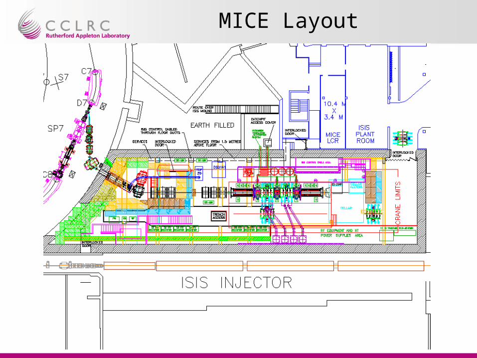
MICE Layout
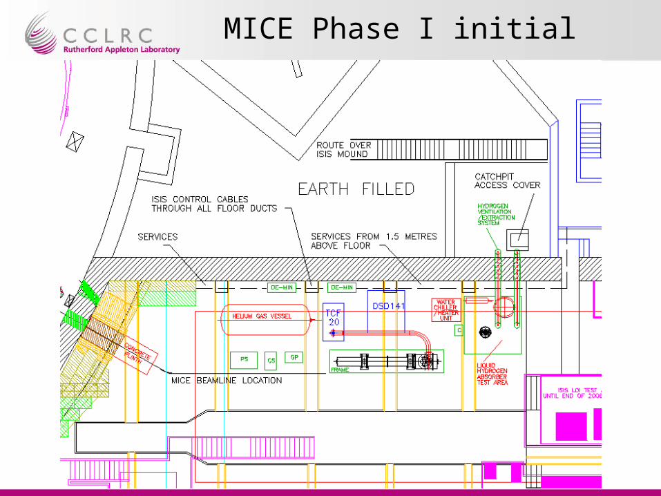
MICE Phase I initial
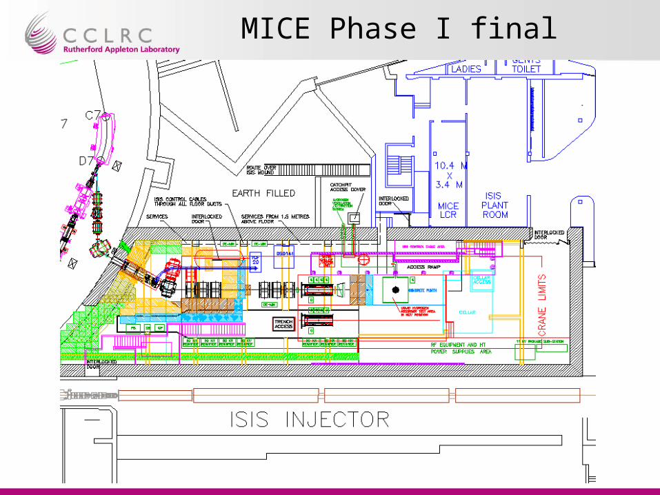
MICE Phase I final
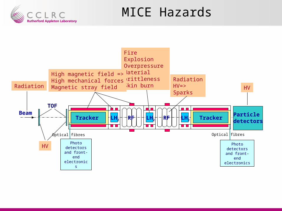
MICE Hazards
Beam
Radiation
FireExplosionOverpressureMaterial brittlenessSkin burn Radiation
HV=>Sparks
HV
RF RFLH2Tracker LH2 LH2 TrackerParticledetectors
High magnetic field =>High mechanical forcesMagnetic stray field
Photo detectorsand front-end
electronics
Optical fibres
Photo detectorsand front-end
electronics
Optical fibres
HV
TOF

Beam
Radiation
RF RFLH2Tracker LH2 LH2 Tracker
Radiation
Particledetectors
Radiation safety is achieved by: - shielding the beam line; - no access to the experimental hall when RF power is on; - local shielding of some bits of cryogenics equipment such as control electronics, cold boxes and valve boxes; - local shielding of detectors front-end electronics
MICE Hazards: Solutions

Beam RF RFLH2Tracker LH2 LH2 Tracker
Particledetectors
High magnetic field =>High mechanical forces
Magnetic field safety is achieved by: - passive magnetic shielding of both the MICE control room and the ISIS linac (brings magnetic field down to below 5 gauss-level in the public areas outside the experimental hall); - restricted access to the experimental hall.
High mechanical forces on the MICE components are:- being analysed and understood ;- taken into the account in the MICE design.
MICE Hazards: Solutions (2)

Beam RF RFLH2Tracker LH2 LH2 Tracker
FireExplosionOverpressureMaterial brittlenessSkin burn
RadiationHV=>Sparks
HV
Particledetectors
Hydrogen safety is achieved by:• careful design of the hydrogen absorber : - FEA analysis of the windows (confirmed by tests); - avoiding cold surfaces where air might be plated; - a double barrier between hydrogen and air.• careful design of the hydrogen system: - a closed system concept keeps hydrogen venting at the minimum; - hydrogen is stored as a solid compound in a hydride bed; - passive pressure relief system is implemented; - hydrogen zone is localised; - ignition sources are kept outside hydrogen zone.• certification of all materials• tests of sub-assemblies and assemblies• test of complete system
MICE Hazards: Solutions (3)
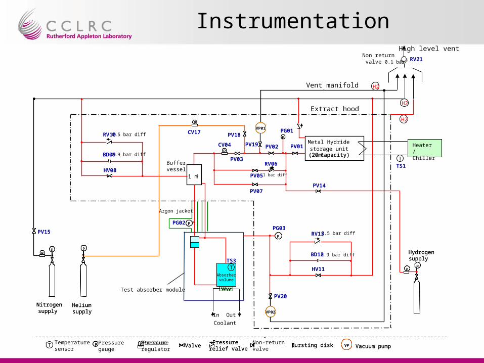
Instrumentation
Pressuregauge
Non-returnvalve
-P P VP Vacuum pumpBursting diskPressure
relief valveValvePressure
P
Chiller/Heater Unit
Helium supply
Hydrogen supply
P
Nitrogen supply
PP
1 m3
P
-P P VP Vacuum pumpBursting diskPressure
relief valveValvePressure
regulator
Coolant
Out
(20m3 capacity)
Metal Hydride storage unit
(20m3 capacity)
P
PP
VP02
VP01
Heater /Chiller
1 bar diff
PP
PP
Helium supply
Hydrogen supply
Extract hood
P
Nitrogen supply
PP
PP
1 m3
Vent manifold
PG01
RV06
PV01
PV18
PV03
PV05
PV07
PG03PPG02
PV20Test absorber module
In
Absorbervolume
0.5 bar diff
0.9 bar diff
PV19CV04
CV17RV10
BD09
HV08
0.5 bar diff RV13
0.9 bar diff BD12
HV11
PV14
High level ventNon return valve 0.1 bar RV21
Buffervessel
PV15
PP
PV02
Argon jacket
TTS3
T
T
TS1
Temperaturesensor
H2
H2
H2

Control logic – Fill SequenceChiller on
Set TS1_sp = TS1_initialPV2,3,5,7,14,17,18,19
closedCV4 closedPV1 open
VP2 on, PV20 open
Cooling System onSet TS2_sp = 15K
Start Pressure Control LoopStart Vac Monitor
Open PV2,3Open CV4
TS1<TS1_spAnd
VG3<1mbar
PG1PG1_sp
Close PV2&3 and CV4Stop Pressure Control Loop
Set TS1_sp = TS1_lowOpen PV5
LS1 > LS1_sp
H2 System Ready
Increment/DecrementTS1
EmptySequence
VG3<1mbar
Vac monitor
Pressure Control
Yes
No
Yes
No Yes
No
Note: ***_sp - set point
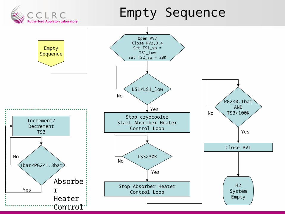
Empty Sequence
Open PV7Close PV2,3,4Set TS1_sp =
TS1_lowSet TS2_sp = 20K
Stop cryocoolerStart Absorber Heater Control Loop
LS1<LS1_low
EmptySequence
Yes
No
Close PV1
PG2<0.1barAND
TS3>100K
H2 System Empty
Yes
No
1bar<PG2<1.3bar
Increment/DecrementTS3
Absorber Heater Control
Yes
No
Stop Absorber Heater Control Loop
TS3>30K
Yes
No
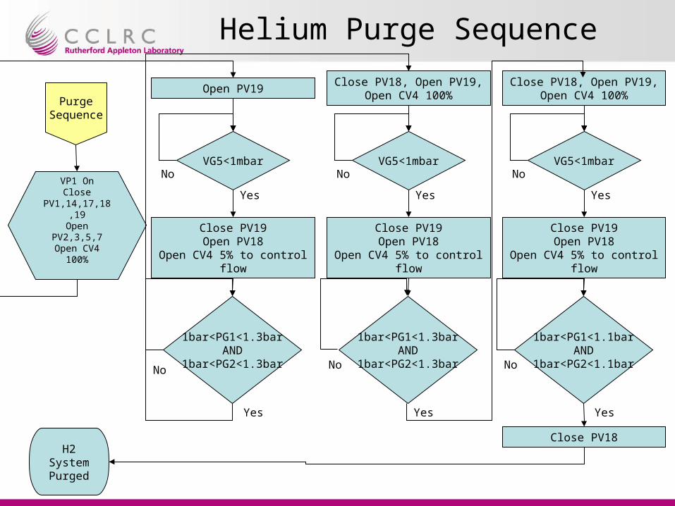
Helium Purge Sequence
VP1 OnClose
PV1,14,17,18,19Open PV2,3,5,7
Open CV4 100%
Close PV19Open PV18
Open CV4 5% to control flow
VG5<1mbar
H2 System Purged
PurgeSequence
No
Open PV19
Yes
1bar<PG1<1.3barAND
1bar<PG2<1.3bar
Close PV19Open PV18
Open CV4 5% to control flow
VG5<1mbarNo
Close PV18, Open PV19, Open CV4 100%
Yes
1bar<PG1<1.3barAND
1bar<PG2<1.3bar
Close PV19Open PV18
Open CV4 5% to control flow
VG5<1mbarNo
Close PV18, Open PV19, Open CV4 100%
Yes
1bar<PG1<1.1barAND
1bar<PG2<1.1bar
YesYesYes
No No No
Close PV18
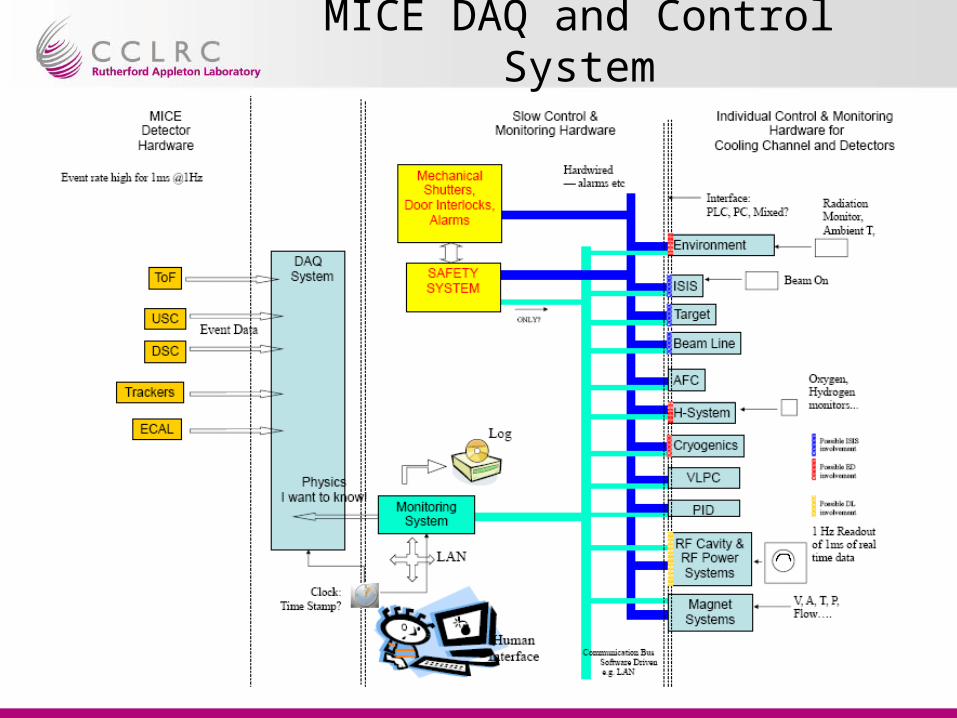
MICE DAQ and Control System
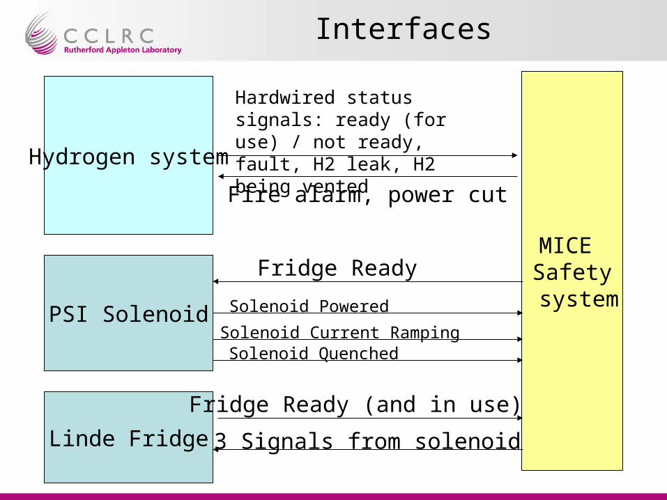
Interfaces
Hydrogen system
MICE Safety system
Hardwired status signals: ready (for use) / not ready, fault, H2 leak, H2 being vented
PSI Solenoid
Linde Fridge
Fridge Ready (and in use)
Fridge Ready
Solenoid Powered
Solenoid Quenched Solenoid Current Ramping
3 Signals from solenoid
Fire alarm, power cut