mgb - american made gas and oil-fired boilers
TRANSCRIPT

MGBCAST IRON GAS FIRED BOILERS
FOR FORCED HOT WATER With Hydrolevel Control
INSTALLATION, OPERATION & MAINTENANCE MANUAL
ModelsMGB-060KMGB-095KMGB-120KMGB-150KMGB-175KMGB-205KMGB-235K
Manufactured by: ECR International Inc.
2201 Dwyer Avenue, Utica, NY 13501 Tel. 800 325 5479
www.ecrinternational.com PN 240012785 REV. C [11/15/2020]
Tested For 50 psi.ASME
Working Pressure
C.S.A. CertifiedFor Natural Gas
Or Propane

2
VERIFY CONTENTS RECEIVED
Fully Assembled Boiler Vent Damper Draft Hood
Pump (Optional)
*Drain Valve *ASME Safety Relief Valve *Tridicator*Black Iron Fittings
(see parts list for sizes and use)
Includes Essential Documents and Warranty
11x17 Wire Diagrams
Document Package *Junction Box *Circulator Harness
Check our website frequently for updates: www.ecrinternational.com
Information and specifications outlined in this manual in effect at thetime of printing of this manual. ECR International reserves the right todiscontinue, change specifications or system design at any time without
notice and without incurring any obligation, whatsoever.
* Items found in parts box included with your boiler.
PN 240012785 Rev. C [11/15/2020]
KEEP THIS MANUAL NEAR BOILER
RETAIN FOR FUTURE REFERENCE
For Parts lists see manual 240012802 included with your boiler literature package.

3
TABLE OF CONTENTS
1 - Physical Data ....................................................................................................................................... 42 - Safety Symbols And Warnings .............................................................................................................. 5
3 - Locating The Boiler .............................................................................................................................. 73.1 Installation Requirements .................................................................................................................. 73.2 Minimum Clearances To Combustible Construction..................................................................................73.3 Recommended Clearances For Service ................................................................................................. 73.4 Boiler Location Considerations ............................................................................................................ 8
4 - Connecting Supply And Return Piping .................................................................................................. 94.1 Connection Locations ........................................................................................................................ 94.2 Safety Relief Valve Installation............................................................................................................94.3 Flush And Rinse System ................................................................................................................. 104.4 Water Treatment ........................................................................................................................... 104.5 Supply And Return Requirements ..................................................................................................... 114.6 Special Conditions .......................................................................................................................... 11
5- Ventilation & Combustion Air .............................................................................................................. 185.1 Requirements................................................................................................................................. 18
6 - Vent System Modification ................................................................................................................... 196.1 Removal Of Existing Boiler From Venting System ................................................................................ 19
7 - Vent Installation ................................................................................................................................ 207.1 Check Your Chimney ....................................................................................................................... 207.2 Requirements................................................................................................................................. 207.3 Chimney Inspection ........................................................................................................................ 207.4 Vent Pipe ....................................................................................................................................... 20
8 - Vent Damper Installation & Instructions ............................................................................................ 218.1 Vent Damper ................................................................................................................................. 21
9 - Connecting Gas Service ...................................................................................................................... 239.1 General ......................................................................................................................................... 239.2 Leak Check Gas Piping .................................................................................................................... 23
10 - Electrical .......................................................................................................................................... 2410.1 Electrical Wiring ............................................................................................................................ 2410.2 Thermostat Installation .................................................................................................................. 24
11 - Wiring Diagrams ............................................................................................................................. 2512 - Lighting Instructions ........................................................................................................................ 27
12.1 Lighting Procedure For Boiler With Intermittent Pilot System................................................................2712.2 Operating Instructions For Intermittent Pilot System...........................................................................2712.3 To Turn Off Gas To The Appliance .................................................................................................... 27
13 - Normal Sequence Of Operation ........................................................................................................ 2813.1 General ....................................................................................................................................... 28
14 - General Maintenance And Care Instructions .................................................................................... 2914.1 Seasonal Startup .......................................................................................................................... 2914.2 Clean Flue Gas Passageways .......................................................................................................... 2914.3 General Maintenance ..................................................................................................................... 3014.4 Adjusting Gas Input ...................................................................................................................... 31
15 - Ratings And Capacities ..................................................................................................................... 32
Appendix A - Control Function ................................................................................................................. 33A-1. Intermittent Pilot........................................................................................................................... 34
Appendix B - Vent Damper Installation ................................................................................................... 36B.1 Damper Installation ........................................................................................................................ 36B.2 Vent Damper ................................................................................................................................. 36B.3 Vent Damper Harness - Molex Plugs .................................................................................................. 37B.4 Vent Damper Troubleshooting Guide.................................................................................................. 38
PN 240012785 Rev. C [11/15/2020]

4
1 - PHYSICAL DATAModel MGB-060K MGB-095K MGB-120K MGB-150K MGB-175K MGB-205K MGB-235K
# Sections 3 4 5 6 7 8 9
A Width with Jacket13-³/8" 13-³/8" 16-1/4" 19" 21-7/8" 27-¹/2" 27-¹/2"
340 mm 340 mm 411 mm 483 mm 555 mm 700 mm 700 mm
B Vent Location (Half Width)6-³/4" 6-³/4" 8-¹/8" 9-¹/2" 10-¹5/16" 13-³/4" 13-³/4"
171 mm 171 mm 206 mm 241 mm 278 mm 349 mm 349 mm
C Height32-¹/8" 32-¹/8" 32-¹/8" 32-¹/8" 32-¹/8" 32-¹/8" 32-¹/8"
816 mm 816 mm 816 mm 816 mm 816 mm 816 mm 816 mm
D Damper Height6" 6" 6-¹/2" 6-¹/2" 7" 7" 7"
153 mm 153 mm 165 mm 165 mm 178 mm 178 mm 178 mm
E Depth w/o Draft Hood Installed22" 22" 22" 22" 22" 22" 22"
559 mm 559 mm 559 mm 559 mm 559 mm 559 mm 559 mm
F Depth W/ Draft Hood Installed26" 26" 26" 26" 26" 26" 26"
660 mm 660 mm 660 mm 660 mm 660 mm 660 mm 660 mm
G Flue Diameter4" 5" 6" 6" 7" 7" 7"
102 mm 127 mm 152 mm 152 mm 178 mm 178 mm 178 mm
Supply & Return Tappings 1-¹/4" NPT 1-¹/4" NPT 1-¹/4" NPT 1-¹/4" NPT 1-¹/4" NPT 1-¹/4" NPT 1-¹/4" NPT
Natural Gas Inlet 1/2" NPT 1/2" NPT 1/2" NPT 1/2" NPT 1/2" NPT 3/4" NPT 3/4" NPT
Relief Valve NPT 3/4" NPT 3/4" NPT 3/4" NPT 3/4" NPT 3/4" NPT 3/4" NPT 3/4" NPT
Drain Valve NPT 3/4" NPT 3/4" NPT 3/4" NPT 3/4" NPT 3/4" NPT 3/4" NPT 3/4" NPT
Heating Water Content, Gal (Liters) 1.9 (7.2) 2.3 (8.8) 2.8 (10.5) 3.2 (12.2) 3.7 (13.9) 4.1 (15.6) 4.6 (17.3)
Air Cushion Tank, Gal (Liters) Estimate.* (Actual Based on System Size)
15 (27)* 30 (114)* 30 (114)* 30 (114)* 30 (114)* 30 (114)* 30 (114)*
Boiler Weight, less pkg - Lbs (KG) 170 (77) 210 (96) 250 (114) 280 (128) 320 (145) 350 (159) 390 (177)
Shipping Weight, lbs (KG) 215 (98) 250 (114) 295 (134) 335 (152) 385 (175) 420 (191) 465 (211)
PN 240012785 Rev. C [11/15/2020]
Figure 1 - DimensionsFront View Right Side View"A"
"B"
"C"
"D"
"G"
2"(50.8 mm)
"F"
21⁵/8"(549.3 mm)
7" (117.8mm)
12¹/2"(317.5 mm)
23" (584mm)7¹/8" (181mm)
16³/8" (416mm)
"E"
GAS SUPPLY

5
2 - SAFETY SYMBOLS AND WARNINGS
CAUTIONIndicates a hazardous situation which, if not avoided, could result in minor or moderate injury.
!!
WARNINGIndicates a hazardous situation which, if not avoided, could result in death or serious injury.
!
DANGERIndicates a hazardous situation which, if not avoided, WILL result in death or serious injury.
!
This is the safety alert symbol. Symbol alerts you to potential personal injury hazards. Obey all safety messages following this symbol to avoid possible injury or death.
Become familiar with symbols identifying potential hazards.
Boiler installation shall be completed by qualified agency.
2.1. Safety Information
WARNINGDo not tamper with or use this boiler for any purpose other than its intended use. Failure to follow these instructions could result in death or serious injury. Use only manufacturer recommended parts and accessories.
!
CAUTIONLaceration, burn hazard. Metal edges and parts may have sharp edges and/or may be hot. Use appropriate personal protection equipment to include safety glasses and gloves when installing or servicing this boiler. Failure to follow these instructions could result in minor or moderate injury.
!!
NOTICEUsed to address practices not related to personal injury.
WARNINGFire, explosion, asphyxiation and electrical shock hazard. Improper installation could result in death or serious injury. Read this manual and understand all requirements before beginning installation.
!
FOR YOUR SAFETY READ BEFORE OPERATING
Hot Water Can Scald!Water heated to temperature for clothes washing, dish washing and other sanitizing needs can scald and cause permanent injury.Children, elderly, and infirm or physically handicapped persons are more likely to be permanently injured by hot water. Never leave them unattended in bathtub or shower. Never allow small children to use a hot water tap or draw their own bath.If anyone using hot water in the building fits the above description, or if state laws or local codes require certain water temperatures at hot water taps, you must take special precautions:• Use lowest possible temperature setting.• Install some type of tempering device, such as
an automatic mixing valve, at hot water tap or water heater. Automatic mixing valve must be selected and installed according to manufacturer's recommendations and instructions.
• Water passing out of drain valves may be extremely hot. To avoid injury:• Make sure all connections are tight.• Direct water flow away from any person.
DANGER!
Water Temperature
Setting
1st Degree Burn Exposure Time For
An Adult
2nd and 3rd Degree Burn Exposure Time For An
Adult120° F 1 minute 5 minutes130° F 5 seconds 30 seconds140° F 2 seconds 5 seconds150° F 1 second 1.5 seconds160° F Instantaneous 0.5 seconds
Note: Warning for Infants, Children, and Elderly: Great care must be taken when exposing the aforementioned groups to warm or hot water as they can be badly burned in exposure times less than half of the time for an adult.
PN 240012785 Rev. C [11/15/2020]

6
WARNINGKeep boiler area clear and free from combustible materials, gasoline and other flammable vapors and liquids.DO NOT obstruct air openings to the boiler room.Modification, substitution or elimination of factory equipped, supplied or specified components may result in personal injury or loss of life.Installation and service of this boiler shall be performed by a qualified installer.When this product is installed in the Commonwealth of Massachusetts the installation shall be performed by a Licensed Plumber or Licensed Gas Fitter.
!
WARNINGCombustion chamber insulation in this product contains ceramic fiber material. Ceramic fibers can be converted to cristobalite in very high temperature applications. The International Agency for Research on Cancer (IARC) has concluded, Crystalline silica inhaled in the form of quartz or cristobalite from occupational sources is carcinogenic to humans (Group1). Avoid breathing dust and contact with skin and eyes. Use NIOSH certified dust respirator (N95). This type of respirator is based on the OSHA requirements for cristobalite at the time this document was written. Other types of respirators may be needed depending on the job site conditions. Current NIOSH recommendations can be found on the NIOSH website https://www.cdc.gov/niosh/topics/silica/. NIOSH approved respirators, manufacturers, and phone numbers are also listed on this website. Wear long-sleeved, loose fitting clothing, gloves, and eye protection. Apply enough water to the combustion chamber lining to prevent dust. Wash potentially contaminated clothes separately from other clothing. Rinse clothes washer thoroughly.
NIOSH stated First Aid. Eye: Irrigate immediately. Breathing: Fresh air.
!
2 - SAFETY SYMBOLS AND WARNINGS
2.2 For Your Safety 2.2 For Your Safety Manufacturer recommends a carbon monoxide detector Manufacturer recommends a carbon monoxide detector located on each floor of your home. Follow your detector's located on each floor of your home. Follow your detector's instructions for operation and verification. Some instructions for operation and verification. Some jurisdictions may, by law, require.jurisdictions may, by law, require.
WARNINGFire, Explosion, Asphyxiation, Electrical shock hazard! Flooding will result in damages such as electrical problems, corrosion, inoperative parts, mold and other unforeseen issues which can occur over time. Any equipment determined by a professional as damaged by a flood, defined as excess of water or other liquid, shall be replaced. Failure to follow these directions will result in a Hazardous Situation.
!
PN 240012785 Rev. C [11/15/2020]
7
1. Installation shall conform to the requirements of the authority having jurisdiction or, in the absence of such requirements, to the National Fuel Gas Code, ANSI Z223.1/NFPA 54, and/or Natural Gas and Propane Installation Code, CAN/CSA B149. Where required by the authority having jurisdiction, the installation must conform to the Standard for Controls and Safety Devices for Automatically fired Boilers, ANSI/ASME CSD-1.
2. Boiler series is classified as a Category I. Vent installation shall be in accordance with "Venting of Equipment", of the National Fuel Gas Code, ANSI Z223.1/NFPA 54, or "Venting Systems and Air Supply for Appliances," of the Natural Gas and Propane Installation Code, CAN/CSA B149.1, or applicable provisions of the local building codes.
3. Boiler has met safe lighting and other performance criteria with the gas manifold and control assembly on the boiler per the latest revision of ANSI Z21.13/CGA 4.9.
4. Install boiler such that gas ignition system components are protected from water (dripping, spraying, rain, etc.) during appliance operation and service, (circulator replacement, condensate trap, control replacement, etc.).
5. Locate boiler on level, solid base as near chimney as possible and centrally located with respect to heat distribution system as practical.
6. Horizontal vent run to chimney shall be as short as practicable. Refer to NFPA 54 to determine maximum permissible horizontal run for chimney type and height.
7. Verify floor will support weight of boiler, water and equipment.
8. Boiler may be installed on combustible floor. Do not install boiler on carpeting.
9. Do not install where gasoline or other flammable liquids or vapors will be stored or used. See Table 3-1 page 8, Contaminants.
10. Chimney shall be lined in a manner acceptable to the authority having jurisdiction.
11. Garage installation boiler shall be 18" above floor.
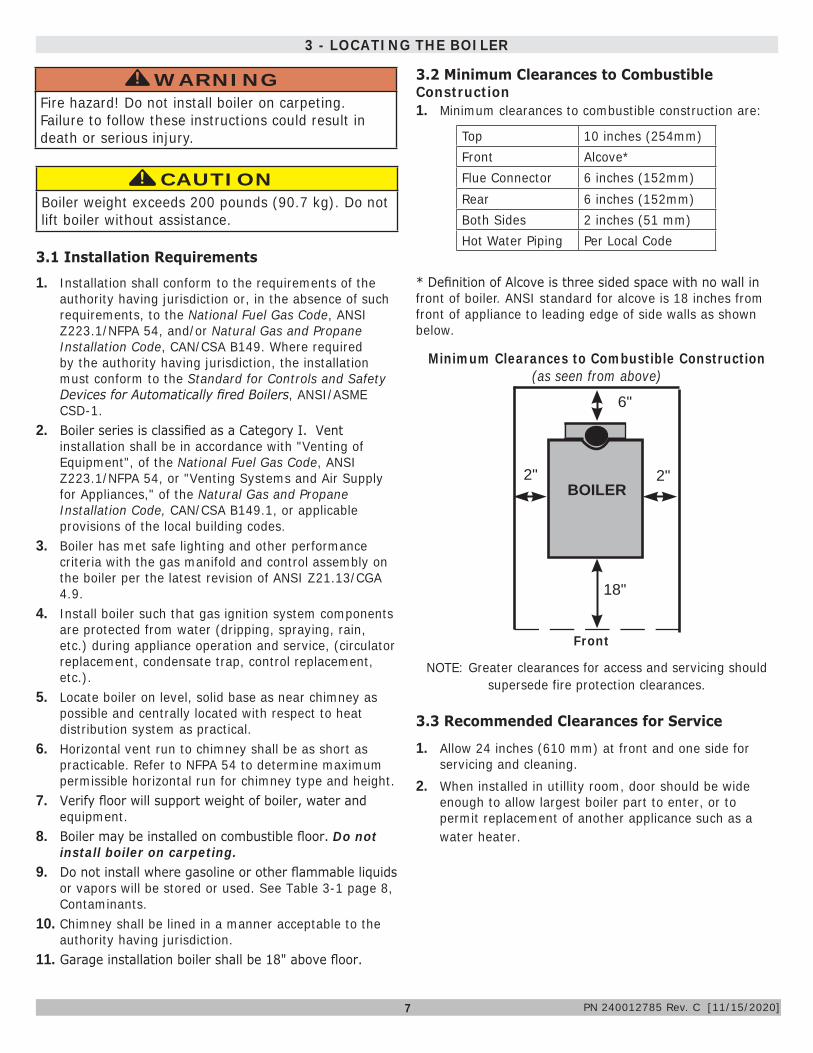
* Definition of Alcove is three sided space with no wall in front of boiler. ANSI standard for alcove is 18 inches from front of appliance to leading edge of side walls as shown below.
3 - LOCATING THE BOILER
Minimum Clearances to Combustible Construction (as seen from above)
3.1 Installation Requirements
3.2 Minimum Clearances to Combustible Construction1. Minimum clearances to combustible construction are:
CAUTIONBoiler weight exceeds 200 pounds (90.7 kg). Do not lift boiler without assistance.
!!
WARNINGFire hazard! Do not install boiler on carpeting. Failure to follow these instructions could result in death or serious injury.
!
2"
6"
BOILER
18"
2"
Front
TOP ............................. 10 IN. (254 mm)FRONT ......................... ALCOVE *FLUE CONNECTOR ......... 6 IN. (152 mm)REAR (DRAFT HOOD) ..... 6 IN. (152 mm)both SIDEs.......................... 2 IN. (51 mm)HOT WATER PIPING ....... Per Local CodeTop 10 inches (254mm)
Front Alcove*Flue Connector 6 inches (152mm)Rear 6 inches (152mm)Both Sides 2 inches (51 mm)Hot Water Piping Per Local Code
3.3 Recommended Clearances for Service
1. Allow 24 inches (610 mm) at front and one side for servicing and cleaning.
2. When installed in utillity room, door should be wide enough to allow largest boiler part to enter, or to permit replacement of another applicance such as a water heater.
NOTE: Greater clearances for access and servicing should supersede fire protection clearances.
PN 240012785 Rev. C [11/15/2020]

8
3.4 Boiler Location Considerations• Ambient room temperature always above 32°F (0°C) to
prevent the potential of freezing.
• Drainage of water (or water/ antifreeze solution) during boiler service or from safety relief valve discharge.
• Access to system water piping, gas supply, and electrical service.
• Boiler shall be installed on flat level surface which is capable of supporting the weight of the boiler, water, and equipment.
• Raise boiler above the floor on blocks if floor may get wet.
• Water, gas, and electrical may connect to either side of boiler as desired.
• Horizontal run to chimney shall be as short as possible.
3 - LOCATING THE BOILER
Items to Avoid Products Which May Contain These Items
Areas Where These Items May Be Found
Chlorine, Fluorine, and Compounds
Spray cans containing chlorofluorocarbonsChlorinated waxes/cleanersChlorine-based swimming pool chemicalsCalcium chloride used for thawingSodium chloride used for water softeningSwimming pool or spa chemicalsDe-icing salts or chemicalsCarbon Tetrachloride
Swimming pools and pool storage areasLaundry room (Note 2)Confined storage areas
Airborne Particulates
Drywall dustRoad or gravel dustDryer lintCat litter
Construction or remodelling areas (Note 1)
Laundry room (Note 2)
Acids, Solvents, etc.
Paint, Varnish, Turpentine, etc.Cleaning SolventsHydrochloric acid/muriatic acidCements, adhesives and glues
Photo processing plantsGarages with workshopsFurniture refinishing areas and establishments
Laundry ChemicalsLaundry detergents, bleaches, fabric softeners, etc.Antistatic fabric softeners (dryer sheets)
Dry cleaning/laundry areas and establishments
Other
Permanent wave solutionsRefrigerants (Freon, etc) (only where the refrigerant may be leaking from the appliance)
Beauty shopsRefrigeration repair shops
Notes:
1. It is recommended the boiler be isolated and not operated during construction/renovation. Excessive particles ingested by the boiler may accumulate in the flueway passages possibly resulting in unsafe operation. In this case, unit servicing shall include cleaning of flueway passages and burner ports.2. If locating boiler in laundry room is unavoidable, it is manufacturer recommended the room be generously ventilated (well in excess of combustible air requirements), and homeowner seal laundry supply containers, and minimize room vapors.3. Piping allowing fresh air in should also be considered. See Section 5-1.
Table 3-1: CONTAMINANTS
• System piping exposed to freezing conditions: Use inhibited propylene glycol solutions certified by fluid manufacturer for use with closed water heating system. Do not use automotive or ethylene glycol.
Maximum recommended mixture 50% glycol.
PN 240012785 Rev. C [11/15/2020]

9
4 - CONNECTING SUPPLY AND RETURN PIPING
Figure 4-1 - Safety Relief Valve
WARNINGBurn and scald hazard. Safety relief valve could discharge steam or hot water during operation. Install discharge piping per these instructions. Failure to follow these instructions could result in death or serious injury.
!
Discharge line shall be installed to relief valve outlet connection to avoid burns, scalding, or water damage due to discharge of steam and/or hot water during operation.Discharge line shall:
4.2 Safety Relief Valve Installation See Figure 4-1
4.1 Connection Locations• Boiler has one supply and one return tapping on each
side (4 total). Boiler supplied with dust caps only. Remove all four (4) caps and plumb before filling boiler with water.
• Supply and return may be piped to either side of boiler, as desired.
• Drain valve may be located off of unused return tapping, as desired.
• ASME relief valve may be located off unused supply tapping IN UPRIGHT POSITION ONLY.
• Unused supply and return tappings may be capped, as desired. Relief valve and drain valve may be located on near boiler piping using contractor supplied tees with no valves.
Check local codes for maximum distance from floor or allowable
safe point of discharge.
RELIEF VALVE On Opposite side of supply
DISCHARGE LINE
WARNINGBurn and scald hazard. Safety relief valve shall be installed with spindle in upright position only, following ASME BPV code. Failure to follow these instructions could result in death or serious injury.
!
A. connect to relief valve outlet and piped down to safe point of disposal. Check local codes for maximum distance from floor or allowable safe point of discharge.
B. be of pipe size equal to or greater than that of the relief valve outlet over the entire length of discharge line;
C. have no intervening shutoff valve between safety relief valve and discharge to atmosphere (do not plug or place any obstruction in discharge line.
D. terminate freely to atmosphere where any discharge will be clearly visible and at no risk of freezing;
E. allow complete drainage of the valve and the discharge line;
F. be independently supported and securely anchored to avoid applied stress on the relief valve;
G. be as short and straight as possible;H. terminate with plain end (not threaded);I. be constructed of material suitable for exposure to
temperatures of 375° F (191°C); or greater.J. Terminate freely to atmosphere where discharge is
clearly visible and no risk of freezing.Refer to local codes and appropriate ASME Boiler and Pressure Vessel Code for additional installation requirements.
Alternate Location Piped in Supply Line(Contractor supplied fittings)
Do Not Install Pressure
Relief Valve Horizontally
PN 240012785 Rev. C [11/15/2020]

10
4 - CONNECTING SUPPLY AND RETURN PIPING
4.3 Flush and Rinse SystemFlush the entire system and rinse thoroughly to ensure no sludge will be introduced into the heating body of the boiler.
WARNING• Poison hazard. Ethylene glycol is toxic. Do not
use ethylene glycol.
• Never use automotive or standard glycol antifreeze, even ethylene glycol made for hydronic systems.
• Ethylene glycol can attack gaskets and seals used in hydronic systems.
• Do not use petroleum based cleaning or sealing compounds boiler system.
• Do not fill boiler or boiler system with softened water.
• Use only inhibited propylene glycol solutions certified by fluid manufacturer as acceptable for use with closed water heating system.
• Thoroughly clean and flush any system that used glycol before installing new Boiler.
• Provide user with Material Safety Data Sheet (MSDS) on fluid used.
NOTICEIf damage due to frozen pipes is a possibility, install appropriate safeguards and alarms on the heating system to prevent property damage due to frozen and burst pipes should the boiler heating system become inoperative due to a power outage, safety lockout or component failure.
4.4 Water TreatmentManufacturer recommends a water analysis be done on water used to fill the system. Treatment may be required based on the analysis results.For hard water or pH below 7.0 consult your local water treatment company.• If CH water is very hard or full of impurities, it must be
adequately filtered and treated, otherwise damage and/or malfunction could be caused. Recommended water quality is:
o Hardness Less than 150 mg/Lo Acidity level 7-8 pHo Sediments Particle size less than 50 micron
• If the water quality is outside these ranges, consult a local water treatment specialist for recommendations.
• If the water is treated, do not use petroleum based products or products containing mineral oil or hydrocarbons in order to avoid likely damage to parts made from rubber compounds (o-rings).
!
PN 240012785 Rev. C [11/15/2020]
!

11
4 - CONNECTING SUPPLY AND RETURN PIPING
4.5 Supply and Return Requirements
1. Boiler used in connection with refrigeration system, install so chilled medium is piped in parallel with boiler with appropriate valves to prevent chilled medium from entering boiler. See Figure 4-2 page 12.
2. Boiler piping system of hot water boiler connected to heating coils located in air handling units where they may be exposed to refrigerated air circulation must be equipped with flow control valves or other automatic means to prevent gravity circulation of boiler water during cooling cycle.
3. Hot water boilers installed above radiation level or as required by authority having jurisdiction shall be provided with low water cut-off device (Factory equipped).
4. Boiler connected to heating system utilizing multiple zoned circulators, each circulator must be supplied with flow control valve to prevent gravity circulation.
5. Hot water boilers and system must be filled with water and maintained to minimum pressure of 12 psi.
4.6 Special Conditions
• System piping exposed to freezing conditions: Use inhibited propylene glycol solutions certified by fluid manufacturer for use with closed water heating system. Do not use automotive or ethylene glycol.
• Boiler installed above radiation level (or as required by authority having jurisdiction). Integral low water cut-off is provided in boiler.
• Boiler used in connection with refrigeration system. Install piping in parallel with boiler, with appropriate valves to prevent chilled medium from entering boiler.
• System piping connected to heating coils located in air handling unit exposed to refrigerated air circulation. Install flow control valves or other automatic means to prevent gravity circulation of boiler water during cooling cycle.
Do not expose boiler and piping to freezing
temperatures. Note
WARNINGAsphyxiation hazard! Gradual flueway blockage resulting from condensate induced corrosion may block boiler passages, resulting in carbon monoxide and or flame rollout. Install bypass piping if return temperature is under 130° F. Failure to follow these instructions could result in death or serious injury.
!
6. Bypass piping gives ability to adjust boiler water temperature to fit system or condition of installation. This method of piping, however, is not typically required for baseboard heating systems. Typical installations where bypass piping is required are as follows:A. This method is used to protect boilers from
condensation forming due to low temperature return water (Below 130° F). Generally noticed in large converted gravity systems other large water volume systems, and in-floor heating systems. Figures 4-3 and 4-4 pages 13-14.
B. These methods are used to protect systems using radiant panels and material they are encased in from high temperature supply water from boiler and protect boiler from condensation.
NOTE#1: When using bypass piping, adjust valves V1 & V2 until desired system temperature is obtained.
NOTE#2: Bypass loop must be same size piping as supply and return piping.
7. Installation using circulators and zone valves are shown in Figures 4-2 through 4-7. For further piping information refer to AHRI Installation and Piping Guide.
8. Install discharge piping from safety relief valve. See Warning, Page 9 and Figure 4-1.
PN 240012785 Rev. C [11/15/2020]

12
4 - CONNECTING SUPPLY AND RETURN PIPING
Circulators in following illustrations are mounted on system supply side, mounting on system return side is also acceptable practice.
BACK FLOW VALVE
PIPING LEGEND:
Figure 4-2 - Circulators Mounted on Supply System, Boiler Used In Configuration with Chiller System. See Special Conditions, Below
DRAIN
PN 240012785 Rev. C [11/15/2020]

13
Figure 4-3 - Bypass Piping With Automatic Mixing Valve
BACK FLOW VALVE
PIPING LEGEND:
4 - CONNECTING SUPPLY AND RETURN PIPING
PURGE VALVE
DRAINVALVE
ASME RELIEF VALVE
BACK FLOW VALVE
PN 240012785 Rev. C [11/15/2020]

14
4 - CONNECTING SUPPLY AND RETURN PIPING
Figure 4-4 - Bypass Piping - Fixed Low Temp Only With Zone Valve
BACK FLOW VALVE
PIPING LEGEND:
ASME RELIEF VALVE
* *
* Manually adjust until proper system temperature is reached.
PN 240012785 Rev. C [11/15/2020]

15
4 - CONNECTING SUPPLY AND RETURN PIPING
Figure 4-5 - Bypass Piping (4-Way Valve Option With Circulator On Supply side)
BACK FLOW VALVE
PIPING LEGEND:
ASME RELIEF VALVE
DRAIN VALVE
FLOW CONTROL VALVE
PN 240012785 Rev. C [11/15/2020]

16
4 - CONNECTING SUPPLY AND RETURN PIPING
Figure 4-6 - Single Zone System With DHW Priority
BACK FLOW VALVE
PIPING LEGEND:
ASME RELIEF VALVE
Back Flow Valve
DRAIN VALVE
PurgeValve
PN 240012785 Rev. C [11/15/2020]
17
4 - CONNECTING SUPPLY AND RETURN PIPING
BACK FLOW VALVE
PIPING LEGEND:
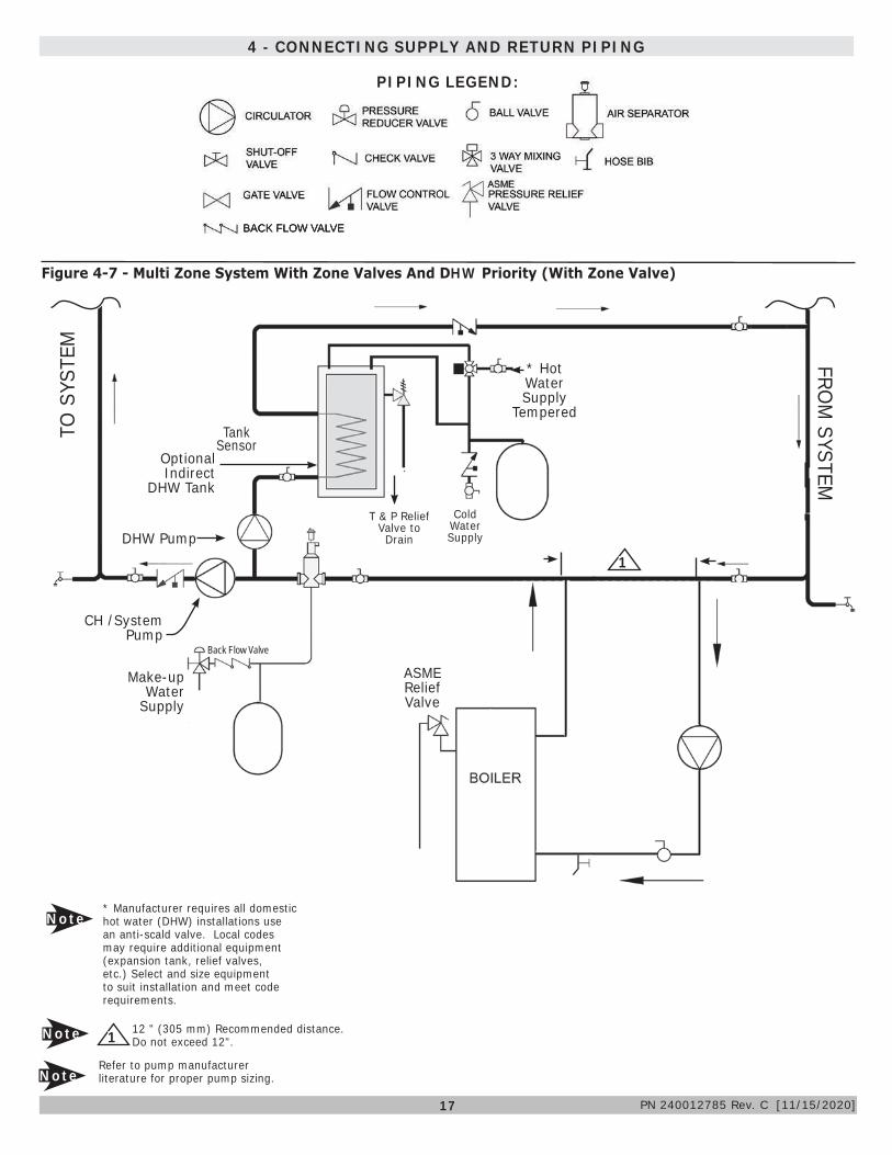
Figure 4-7 - Multi Zone System With Zone Valves And DHW Priority (With Zone Valve)
T & P Relief Valve to Drain
Cold Water Supply
Optional Indirect
DHW Tank
Make-up Water
Supply
Tank Sensor
CH /System Pump
ASME Relief Valve
1DHW Pump
12 " (305 mm) Recommended distance. Do not exceed 12".Note
Note* Manufacturer requires all domestic hot water (DHW) installations use an anti-scald valve. Local codes may require additional equipment (expansion tank, relief valves, etc.) Select and size equipment to suit installation and meet code requirements.
* Hot Water Supply
Tempered
NoteRefer to pump manufacturer literature for proper pump sizing.
TO S
YSTE
MFRO
M SYSTEM
1
Back Flow Valve
PN 240012785 Rev. C [11/15/2020]
18
5- VENTILATION & COMBUSTION AIR
Room Cubic Feet Volume
# Sections
Input BTU/HR
Standard Method
Known Air Infiltration Rate Method (ACH - Air Changes Per Hour)0.1 0.2 0.3 0.4 0.5 0.6
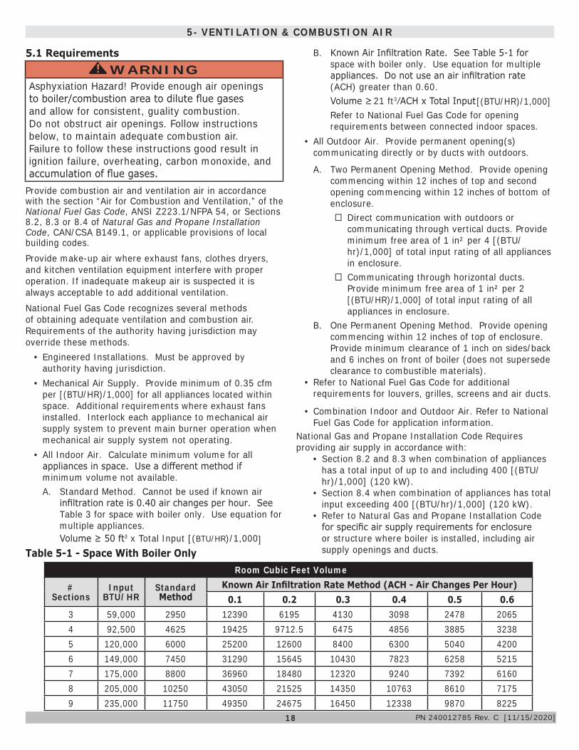
3 59,000 2950 12390 6195 4130 3098 2478 20654 92,500 4625 19425 9712.5 6475 4856 3885 32385 120,000 6000 25200 12600 8400 6300 5040 42006 149,000 7450 31290 15645 10430 7823 6258 52157 175,000 8800 36960 18480 12320 9240 7392 61608 205,000 10250 43050 21525 14350 10763 8610 71759 235,000 11750 49350 24675 16450 12338 9870 8225
Table 5-1 - Space With Boiler Only
5.1 Requirements
Provide combustion air and ventilation air in accordance with the section “Air for Combustion and Ventilation,” of the National Fuel Gas Code, ANSI Z223.1/NFPA 54, or Sections 8.2, 8.3 or 8.4 of Natural Gas and Propane Installation Code, CAN/CSA B149.1, or applicable provisions of local building codes.Provide make-up air where exhaust fans, clothes dryers, and kitchen ventilation equipment interfere with proper operation. If inadequate makeup air is suspected it is always acceptable to add additional ventilation.National Fuel Gas Code recognizes several methods of obtaining adequate ventilation and combustion air. Requirements of the authority having jurisdiction may override these methods.
• Engineered Installations. Must be approved by authority having jurisdiction.
• Mechanical Air Supply. Provide minimum of 0.35 cfm per [(BTU/HR)/1,000] for all appliances located within space. Additional requirements where exhaust fans installed. Interlock each appliance to mechanical air supply system to prevent main burner operation when mechanical air supply system not operating.
• All Indoor Air. Calculate minimum volume for all appliances in space. Use a different method if minimum volume not available.A. Standard Method. Cannot be used if known air
infiltration rate is 0.40 air changes per hour. See Table 3 for space with boiler only. Use equation for multiple appliances.Volume ≥ 50 ft3 x Total Input [(BTU/HR)/1,000]
B. Known Air Infiltration Rate. See Table 5-1 for space with boiler only. Use equation for multiple appliances. Do not use an air infiltration rate (ACH) greater than 0.60.Volume ≥ 21 ft3⁄ACH x Total Input Refer to National Fuel Gas Code for opening requirements between connected indoor spaces.
• All Outdoor Air. Provide permanent opening(s) communicating directly or by ducts with outdoors.
A. Two Permanent Opening Method. Provide opening commencing within 12 inches of top and second opening commencing within 12 inches of bottom of enclosure.
� Direct communication with outdoors or communicating through vertical ducts. Provide minimum free area of 1 in² per 4 [(BTU/hr)/1,000] of total input rating of all appliances in enclosure.
� Communicating through horizontal ducts. Provide minimum free area of 1 in² per 2 [(BTU/HR)/1,000] of total input rating of all appliances in enclosure.
B. One Permanent Opening Method. Provide opening commencing within 12 inches of top of enclosure. Provide minimum clearance of 1 inch on sides/back and 6 inches on front of boiler (does not supersede clearance to combustible materials).
• Refer to National Fuel Gas Code for additional requirements for louvers, grilles, screens and air ducts.
• Combination Indoor and Outdoor Air. Refer to National Fuel Gas Code for application information.
National Gas and Propane Installation Code Requires providing air supply in accordance with:
• Section 8.2 and 8.3 when combination of appliances has a total input of up to and including 400 [(BTU/hr)/1,000] (120 kW).
• Section 8.4 when combination of appliances has total input exceeding 400 [(BTU/hr)/1,000] (120 kW).
• Refer to Natural Gas and Propane Installation Code for specific air supply requirements for enclosure or structure where boiler is installed, including air supply openings and ducts.
WARNINGAsphyxiation Hazard! Provide enough air openings to boiler/combustion area to dilute flue gases and allow for consistent, guality combustion. Do not obstruct air openings. Follow instructions below, to maintain adequate combustion air. Failure to follow these instructions good result in ignition failure, overheating, carbon monoxide, and accumulation of flue gases.
!
[(BTU/HR)/1,000]
PN 240012785 Rev. C [11/15/2020]

19
When an existing boiler is removed from a common venting system, the system is likely too large for proper venting of appliances still connected to it. If this occurs, follow this test procedure:
6 - VENT SYSTEM MODIFICATION
At time of removal of an existing boiler, the following steps shall be followed with each appliance remaining connected to the common venting system placed in operation, while the other appliances remaining connected to the common venting system are not in operation.1. Seal an unused opening in the common venting
system.2. Visually inspect the venting system for proper size and
horizontal pitch and determine there is no blockage or restriction, leakage, corrosion and other deficiencies which could cause an unsafe condition.
3. Insofar as is practical, close all building doors and windows and all doors between the space in which the appliances remaining connected to the common venting system are located and other spaces of the building. Turn on clothes dryers and any other appliance not connected to the common venting system. Turn on any exhaust fans, such as range hoods and bathroom exhausts, so they operate at maximum speed. Do not operate a summer exhaust fan. Close fireplace dampers.
4. Place in operation the appliance being inspected. Follow the lighting instructions. Adjust thermostat so appliance will operate continuously.
5. Test for spillage at the draft hood relief opening after 5 minutes of main burner operation. Use the flame of a match or candle, or smoke from a cigarette, cigar or pipe.
6. Minimum draft should be -.02" w.c.7. After it has been determined that each appliance
remaining connected to a common venting system properly vents when tested as outlined above, return doors, windows, exhaust fans, fireplace dampers and any other gas burning appliances to their previous condition of use.
8. Any improper operation of the common venting system should be corrected so the installation conforms with the National Fuel gas Code, ANSI Z223.1/NFPA 54, and/or the Natural Gas and Propane Installation Code, CAN/CSA B149.1. When re-sizing any portion of the common venting system, the common venting system should be re-sized to approach the minimum size determined using the appropriate tables in Chapter 13 of the National Fuel Gas Code, ANSI Z223.1/NFPA 54, and/or the Natural Gas and Propane Installation Code, CAN/CSA B149.1.
9. Draft pressure must be negative under all conditions with all aplliances operating.
6.1 Removal Of Existing Boiler From Venting SystemFigure 6-1 - Typical Masonry Chimney Requirements
See NFPA for Installation Specifications Type B Vent Masonry Chimney Requirements
PN 240012785 Rev. C [11/15/2020]

20
7 - VENT INSTALLATION
WARNINGBoiler and venting installations shall be performed by a qualified expert and in accordance with the appropriate manual. Installing or venting boiler or other gas appliance with improper methods or materials may result in serious injury or death due to fire or to asphyxiation from poisonous gases such as carbon monoxide which is odorless and invisible.
!
WARNINGDo not connect boiler to any portion of mechanical draft system operating under positive pressure.
!
7.1 Check Your ChimneyIt must be clean, the right size, properly constructed and in good condition. A chimney shall be lined in a manner acceptable to the authority having jurisdiction.
Chimney SizingChimney sizing, and vent installation must be in accordance with The National Fuel Gas Code, ANSI Z223.1/NFPA 54 or CAN/CSA B149.1, or applicable provisions of local building codes.
This is a high efficiency boiler with low stack temperature. Following recommendations are in addition to requirements of the National Fuel Gas Code.1. Type B double wall vent pipe is recommended for vent
connector. Single wall vent connectors should not be used unless following conditions are true:a. Except for basement, boiler is not installed in
unheated space.b. Total horizontal portion of vent connector, not
including elbows is less than 5 feet in length.2. Outside chimneys (i.e. chimneys exposed to outdoors
below roof line on one or more sides) do not use unless they are:a. enclosed in a chase, orb. lined with type B vent pipe, or listed flexible vent
liner, or other certified chimney lining system. 3. Where possible it is recommended to common vent
boiler and water heater.4. For multiple Category I boiler installations, consult
boiler manufacturer for venting recommendations.5. Minimize horizontal vent length.
1. Vent pipe must slope upward from the boiler not less than ¼ inch for every 1 foot (21 mm/m) to verticle vent terminal.
2. Horizontal portions of venting system shall be supported rigidly every 5 feet and at the elbows. No portion of vent pipe should have any dips or sags.
7.2 Requirements
7.3 Chimney InspectionChimney must be clean, right size, properly constructed and in good condition. Installation must conform to requirements of the authority having jurisdiction or, in absence of such requirements, to The National Fuel Gas Code, ANSI Z223.1/NFPA 54.
7.4 Vent Pipe• Connect draft hood to boiler using 2 screws (provided)
onto flue collector. Connect two safety circuit wires (attached to vent damper harness) to blocked vent switch. See Figure 13-1.
• Fasten sections of vent pipe with 3 sheet metal screws at each joint to make piping rigid.
• Support horizontal portions of vent system to prevent sagging.
• Use stove pipe wires or metal strapping every 5’ to support pipe from above.
• Vent pipe through crawl space, use double wall vent pipe.
• Vent pipe passing through combustible wall or partition, use ventilated metal thimble. Thimble should be 4" larger in diameter than vent pipe.
NOTICEMinimum Vent Pipe Clearance - Wood and other combustible materials must not be closer than 6” from any surface of single wall metal vent pipe. Listed Type B vent pipe or other listed venting systems shall be installed in accordance with their listing.
3. Boiler series is classified as a Category I. Vent installation shall be in accordance with "Venting of Equipment," of the National Fuel Gas Code, ANSI Z223.1/NFPA 54, or "Venting Systems and Air Supply for Appliances," of the Natural Fuel Gas and Propane Installation Code, CAN/CSA B149.1, or applicable provisions of the local building codes.
4. Inspect chimney. Chimney shall be lined. Verify chimney is constructed according to NFPA 211 and NFPA 54. Vent or vent connector shall be Type B or metal pipe having resistance to heat and corrosion not less than that of galvanized sheet steel or aluminum not less than 26 gauge thick, 24 gauge for 6 and 7 inch.
5. Connect flue pipe from draft hood to chimney. Bolt or screw joints together to avoid sags. Flue pipe should not extend beyond inside wall of chimney more than 1/4 inch. Do not install manual damper in flue pipe or reduce size of flue outlet except as provided by the latest revision of National Fuel Gas Code, ANSI ANSI Z223.1/NFPA 54 or CAN/CSA B149.1. Protect combustible ceiling and walls near flue pipe as required by National Fuel Gas Code. Where two or more appliances vent into a common flue, the area of the common flue must be at least equal to the area of the largest flue plus 50 percent of the area of each additional flue.
PN 240012785 Rev. C [11/15/2020]

21
8 - VENT DAMPER INSTALLATION & INSTRUCTIONS
Connecting The Vent Damper And Vent ConnectorRefer to page 4 for size and location of vent (flue opening).
NOTICEDamper blade on furnished vent damper has 1/2 square inch hole (approximately 3/4” diameter). Boilers equipped with intermittent ignition, hole should be plugged by using plug supplied with vent damper.
1. Follow damper installation instructions provided with damper.
2. Position furnished vent damper on top of flue outlet collar. Fasten damper securely to flue outlet collar with sheet metal screws. Verify damper blade has clearance to operate inside of diverter. Do not modify either draft diverter or vent damper during installation.
As An OptionDamper may be installed in horizontal or vertical position, closer to flue outlet collar preferred. See Figures 8-1, 8-2, 8-3 and enclosed vent damper instructions.
3. Install vent damper to service only single boiler for which it is intended. Damper position indicator shall be in visible location following installation. Locate damper so it is accessible for servicing. See Figure 8-2 page 22.
4. Damper must be in the open position when appliance main burners are operating.
5. Boiler is equipped with factory wired harness that plugs into vent damper.
6. Slope pipe up from boiler to chimney not less than 1/4” per foot.
7. Run pipe as directly as possible with as few elbows as possible.
8. Do not connect to fireplace flue.9. End of vent pipe must be flush with inside face of
chimney flue. Use a sealed-in thimble for chimney connection.
10. Clearance of not less than 6 inches (152mm) between Vent Damper and combustible material must be maintained. Additional clearance should be allowed for service of Vent Damper.
11. Vent Damper position indicator must be in visible location following installation.
Fasten sections of vent pipe with sheet metal screws to make piping rigid. Support horizontal potions of vent system to prevent sagging. Use stovepipe wires every 5’ to support pipe from above. Use double wall vent pipe if vent pipe must go through crawl space. Where vent pipe passes through combustible wall or partition, use ventilated metal thimble. Thimble should be 4 inches larger in diameter than vent pipe.
Figure 8-1 - Vent Damper Installation
8.1 Vent Damper
PN 240012785 Rev. C [11/15/2020]

22
Figure 8-2 - Vent Damper Placement
Figure 8-3 - Vent Damper Position Indicator
8 - VENT DAMPER INSTALLATION & INSTRUCTIONS
PN 240012785 Rev. C [11/15/2020]

23
9 - CONNECTING GAS SERVICE
9.1 General• Use piping materials and joining methods acceptable
to authority having jurisdiction. In absence of such requirements: USA - National Fuel gas Code, ANSI Z223.1/NFPA 54
• Canada - Natural Gas and Propane Installation Code, CAN/CSA B149.1
• Size and install gas piping system to provide sufficient gas supply to meet maximum input at not less than minimum supply pressure. See Table 9-1.
• Support piping with hooks, straps, bands, brackets, hangers, or building structure components to prevent or dampen excessive vibrations and prevent strain on gas connection. Boiler will not support piping weight.
• Use thread (joint) compound (pipe dope) suitable for liquefied petroleum gas.
• Install field sourced manual main shutoff valve, ground joint union, and sediment trap upstream of gas valve. See Figure 9-1.
MAXIMUM CAPACITY OF PIPE IN CUBIC FEET OF GAS/HOUR(Gas Pressure = 0.5 psig or less, Pressure Drop = 5 in. w/c)
Table 9-2
Length of Pipe (Feet)
Nominal Iron Pipe Size
½” ¾” 1” 1¼”
10 175 360 680 1400
20 120 250 465 950
30 97 200 375 770
40 82 170 320 660
60 66 138 260 530
80 57 118 220 460
100 50 103 195 400
For additional information refer to the National Fuel Gas Code Handbook.
Figure 9-1 - Gas Piping
CAUTIONWHAT TO DO IF YOU SMELL GAS
• Do not try to light any appliance.• Do not touch any electrical switch; do not use
any phone in your building.• Immediately call your gas supplier from a
neighbor’s phone. Follow gas supplier’s instructions.
• If you cannot reach your gas supplier, call the fire department.
!!
INSTALL MANUAL VALVE WITHIN 6 FT. (183 cm) OF BOILER AND 5 FT. (152 cm) ABOVE THE FLOOR WHERE REQUIRED BY LOCAL CODES
3" (8 cm) Minimum
Sediment Trap
To Gas Control Inlet
DANGERFire Hazard. Do not use matches, candles, open flames, or other methods providing ignition source. Failure to comply will result in death or serious injury.
!
WARNINGFire, explosion, asphyxiation and burn hazard. Boiler piping and gas connections shall be leak tested before placing boiler in operation. Failure to follow these instructions and or improper installation could result in death or serious injury.
!
NOTICEUse of CSA approved corrugated, semi-rigid stainless steel tubing with polyethylene jacketing is approved for use with boilers following tubing manufacturer's instructions. Use of flexible appliance gas tubing also known as a "whip" is not allowed per NFPA 54.
Table 9-1 Natural Gas PropaneMin. Supply Pressure 5" w.c. 11" w.c.
Max. Supply Pressure 13.5" w.c. 13.5" w.c.
Manifold Pressure 3.5" w.c.10" w.c.
(4 sec. only) 10.5" w.c.
9.2 Leak Check Gas PipingPressure test boiler and gas connection before placing boiler in operation.• Pressure test over 1/2 psig (3.5 kPa). Disconnect
boiler and its individual gas shutoff valve from gas supply system.
• Pressure test at 1/2 psig (3.5 kPa) or less. Isolate boiler from gas supply system by closing manual gas shutoff valve.
• Locate leakage using gas detector, non-corrosive detection fluid, or other leak detection method acceptable to authority having jurisdiction. Do not use matches, candles, open flames, or other methods providing ignition source.
• Correct leaks immediately and retest.
Union Recommended
for service
PN 240012785 Rev. C [11/15/2020]

24
10 - ELECTRICAL
10.1 Electrical WiringIf an external electrical source is utilized, the boiler, when installed, must be electrically bonded to ground in accordance with the requirements of the authority having jurisdiction or, in the absence of such requirements, with the National Electrical Code, ANSI/NFPA 70, and/or the Canadian Electrical Code Part I, CSA C22.1, Electrical Code.
See wiring diagrams on the following pages for details.
• J-box and circulator harness are shipped in parts box, and may be wired on either side of boiler as desired.
• Electrically bond boiler to ground in accordance with requirements of authority having jurisdiction. Refer to: USA - National Electrical Code, ANSI/NFPA 70.
• Aluminum wiring/conductors not permitted.
10.2 Thermostat Installation
1. Use a thermostat with dry contacts which does not pull any load from the control. Use a separate transformer for zone valve wiring.
2. Thermostat should be installed on inside wall about four feet above floor.
3. NEVER install thermostat on outside wall. 4. Do not install thermostat where it will be affected by
drafts, hot or cold pipes, sunlight, lighting fixtures, televisions, fireplace, or chimney.
5. Check thermostat operation by raising and lowering thermostat setting as required to start and stop burners.
6. Instructions for final adjustment of thermostat are packaged with thermostat (adjusting heating anticipator, calibration, etc.)
7. Thermostat's heat anticipator must be adjusted to
WARNINGElectrical shock hazard. Turn OFF electrical power supply at service panel before making electrical connections. Failure to do so could result in death or serious injury.
!
WARNINGFire, electrical shock hazard. Verify all electrical connections are secure. Failure to do so could result in death or serious injury.
!
match total current draw of all controls associated with boiler during heating cycle.
8. There are two (2) options when using Zone 2 for an indirect tank or heating zone using the IC control to power the Zone 2 pump:a. A Zone 2 wiring kit is available see parts list. This
plugs into the Molex connector for the Zone 2 pump and provides power leads for the pump.
b. Cut off the end of the Molex connector and wire the Zone 2 pump leads directly using wire nuts or other approved electrical connectors.
PN 240012785 Rev. C [11/15/2020]

25
11 - WIRING DIAGRAMS
Figure 11-1 - 3200 Plus Fuel Smart Hydrostat Control
WARNINGModification, substitution or elimination of factory equipped, supplied or specified components may result in personal injury or loss of life.
!
PN 240012785 Rev. C [11/15/2020]

26
11 - WIRING DIAGRAM
Figure 11-2 -3200 Plus Fuel Smart Hydrostat Control - ladder
PN 240012785 Rev. C [11/15/2020]

27
12 - LIGHTING INSTRUCTIONS
12.1 Lighting Procedure For Boiler With Intermittent Pilot SystemThis appliance is equipped with an ignition device which automatically lights the pilot. Do not try to light the appliance by hand.
12.2 Operating Instructions For Intermittent Pilot System
1. STOP! Read and follow all safety information.2. Set the thermostat to lowest setting.3. Turn off all electric power to the appliance.4. This appliance is equipped with an ignition device which
automatically lights the pilot. Do not try to light the pilot by hand.
5. Lift and remove front panel.
Figure 12-1 - Intermittent Pilot
6. Turn gas control knob clockwise to “OFF.”
7. Wait (5) minutes to clear out any gas. If you then smell gas, STOP! Follow “What To Do If You Smell Gas” in the safety information to the left. If you don’t smell gas, go on to the next step.
8. Turn gas control knob counterclockwise to “ON.”
9. Turn on all electric power to the appliance.
10. Set thermostat to desired setting.
11. If the appliance will not operate, follow the instructions “To Turn Off Gas To Appliance” , and call qualified service technician or your gas supplier.
12. Replace front panel
12.3 TO TURN OFF GAS TO THE APPLIANCE
1. Set the thermostat to lowest setting.2. Turn off all electric power to the appliance if service is
to be performed.3. Lift and remove front panel.4. Push in gas control knob slightly and turn clockwise
to "OFF." DO NOT FORCE.5. Call qualified service technician.
WARNINGIf you do not follow these instructions exactly, a fire or explosion may result causing property damage, personal injury or loss of life.• This appliance is equipped with an ignition device
which automatically lights burner. Do NOT try to light this burner by hand.
• Before operating smell all around appliance area for gas. Be sure to smell next to floor because some gas is heavier than air and will settle to the floor.
• Use only your hand to turn the gas shutoff valve. Never use tools. If valve will not turn by hand, do not try to repair it, call a qualified service technician. Force or attempted repair may result in fire or explosion.
• Do not use this appliance if any part has been under water. Immediately call a qualified service technician to inspect appliance and to replace any part of control system and any gas control which has been under water.
!
NOTICEBefore lighting any type of pilot burner, verify the hot water boiler and system are full of water to minimum pressure of 12 psi in the system, also verify system is vented of air. Set operating control of thermostat to “below” normal setting. Refer to following appropriate lighting instruction.
CAUTIONWHAT TO DO IF YOU SMELL GAS
• Do not try to light any appliance.
• Do not touch any electrical switches; do not use any phone in your building.
• Immediately call your gas supplier from a neighbor’s phone. Follow the gas supplier’s instructions.
• If you cannot reach your gas supplier, call the fire department.
!!
PN 240012785 Rev. C [11/15/2020]

28
13 - NORMAL SEQUENCE OF OPERATION
1. Thermostat actuates on call for heat, completing circuit to control. A. Completed circuit to control will energize the vent
damper. The circulator will be energized if the boiler water temperature is above 125°F.
B. When the vent damper is fully open the damper end switch completes the circuit to ignition system, ignition takes place.
C. Circulator will activate if temperature is 125°F or more.
2. In event the boiler water temperature exceeds high limit setting on the boiler mounted high limit control, power is interrupted between control system and ignition system.
Blocked Vent Safety Switch
Rollout Switch
Base
Burner Door
Figure 13-1 Blocked Vent Safety Switch, Roll-out Safety Switch (Front Panel Removed)
13.1 General
Gas Valve
Igniter
Burners
Hydrolevel Control
View Port
WARNINGBurn Hazard. View port on burner door may be hot. Wear personal protection when servicing this boiler.
!
WARNINGFire and Asphyxiation hazard. Do not attempt to place boiler in operation if safety switches shut the main burner gas off. Contact a qualified service agency. Failure to follow these instructions could result in death or serious injury.
!
Ignition Control
A. Power remains off until boiler water temperature drops below high limit setting.
B. Circulator continues to operate under this condition until thermostat is satisfied.
3. In event the flow of combustion products through the boiler venting system becomes blocked: A. Blocked vent safety switch shuts main burner gas
off. B. If boiler flue-way becomes blocked: flame rollout
safety switch shuts main burner gas off. See Figure 13-1.
4. 2-Zone Capability: The Hydrostat IC is equipped with a second zone for use with a 120-volt circulator. This zone is factory set to function with an indirect water heater for domestic hot water (DHW). The control allows the boiler to run up to high limit setting to satisfy calls from this zone. The control will allow the Smart DHW Priority feature to prioritize domestic hot water. The second zone can also be used for a heating zone – in which case it should not be prioritized. See Zone 2 settings in the Hydrolevel Manual provided with your boiler.
If either of these condition A or B exist: Do not attempt to place boiler back into operation. Contact certified service agency. Do Not jumper safety switch(s).
For detailed sequence of control, see Appendix A.
Flue Inspection
Cover
PN 240012785 Rev. C [11/15/2020]

29
14 - GENERAL MAINTENANCE AND CARE INSTRUCTIONS
• Before seasonal start-up, have a certified service agency check boiler for soot and scale in flues, clean burners and check gas input rate to maintain high operating efficiency.
• Verify proper operation after servicing.• Service agency will verify system is filled with water to
minimum pressure and open air vents, if used, to expel any air accumulated in the system. Check entire piping system and, if any leaks appear, have them repaired.
• Circulators need to be checked and maintained. Refer to circulator manufacturer's instructions.
• Inspect venting system at the start of each heating season. ◊ Check vent pipe from boiler to chimney for signs
of deterioration by rust or sagging joints. Repair if necessary.
◊ Remove vent pipe at base of chimney or flue and using a mirror, check vent for obstruction and verify vent is in good working order.
• Boiler flue gas passageways may be inspected by a light and mirror. ◊ Remove burner door. See Figure 13-1 page 28. ◊ Place trouble lamp in flue collector through draft relief
opening or flue inspection cover. ◊ With mirror positioned above burners, flue gas
passageways can be checked for soot or scale
Follow this procedure to clean flue gas passageways:1. Remove burner tray from heat exchanger by
disconnecting the gas supply, by removing two (2) nuts. Pull out the assembly. see Figure 14-1 page 30.
2. Remove top jacket panel.3. Remove flue inspection cover.4. Place sheet of heavy paper or similar material over
bottom of base and brush down flue passageways. Soot and scale will collect on paper and is easily removed with the paper.
5. With paper still in place in base, clean top of boiler castings of boiler putty or silicone used to seal between castings and flue collector. Verify chips are not lodged in flue passageways.
When cleaning process is complete, restore boiler components to their original position. Use IS-808 GE silicone (available from distributor) to seal around flue collector, and inspection cover if required.
WARNINGLabel all wires prior to disconnection when servicing controls. Wiring errors could cause improper and dangerous operation.
!
14.1 Seasonal Startup
14.2 Clean Flue Gas Passageways
PN 240012785 Rev. C [11/15/2020]

30
Figure 14-3 - Gas Burner Flame
Figure 14-2 - Gas Burner Pilot Assembly
Figure 14-1 - Burner Tray
BURNERS
ORIFICES
GAS VALVE
• Visually inspect main burner and pilot flames at start of heating season and again in mid-season. ◊ Main burner flame should have well defined inner
blue mantel with lighter blue outer mantel. ◊ Check burner throats and burner orifices for lint or
dust obstruction. Figures 14-1 and 14-3.
• Pilot flame should envelop ⅜ to ½ inch of tip of ignition/sensing electrode. See Figure 14-2.
• To adjust pilot flame: remove pilot adjustment cover screw and turn inner adjustment screw counterclockwise to increase or clockwise to decrease pilot flame. Replace cover screw after adjustment to prevent possible gas leakage. See Figure 12-1, Page 27.
• Check burners and pilot for signs of corrosion, rust or scale buildup.
• Area around boiler shall be clear and free of combustible materials, gasoline and other flammable vapors and liquids.
• Free flow of combustion and ventilating air to boiler and boiler room shall not be restricted or blocked.
• Inspect factory supplied and field sourced low water cutoffs annually, or as recommended by low water cutoff manufacturer. Flush float type low water cutoffs per manufacturer's instructions.
• Contact a Qualified Service Agency to make annual inspection of boiler and heating system. This should include:
1. Check casting and vent for signs of corrosion from condensate.
2. Examine pilot lint screen and clean if needed.
3. Check venting for any signs of corrosion, rust, damage or deterioration. Contact a Qualified Service Agency immediately if you observe any of these conditions.
4. Clean oxidation on the igniter/flame sensor with an abrasive cloth.
14.3 General Maintenance
14 - GENERAL MAINTENANCE AND CARE INSTRUCTIONS
INNER BLUE MANTEL
LIGHT BLUE OUTER MANTEL
3/8" to 1/2 " (9.5 to 12.7mm)
PILOT LINT SCREEN
Proper Flame Adjustment Shown
PN 240012785 Rev. C [11/15/2020]
31
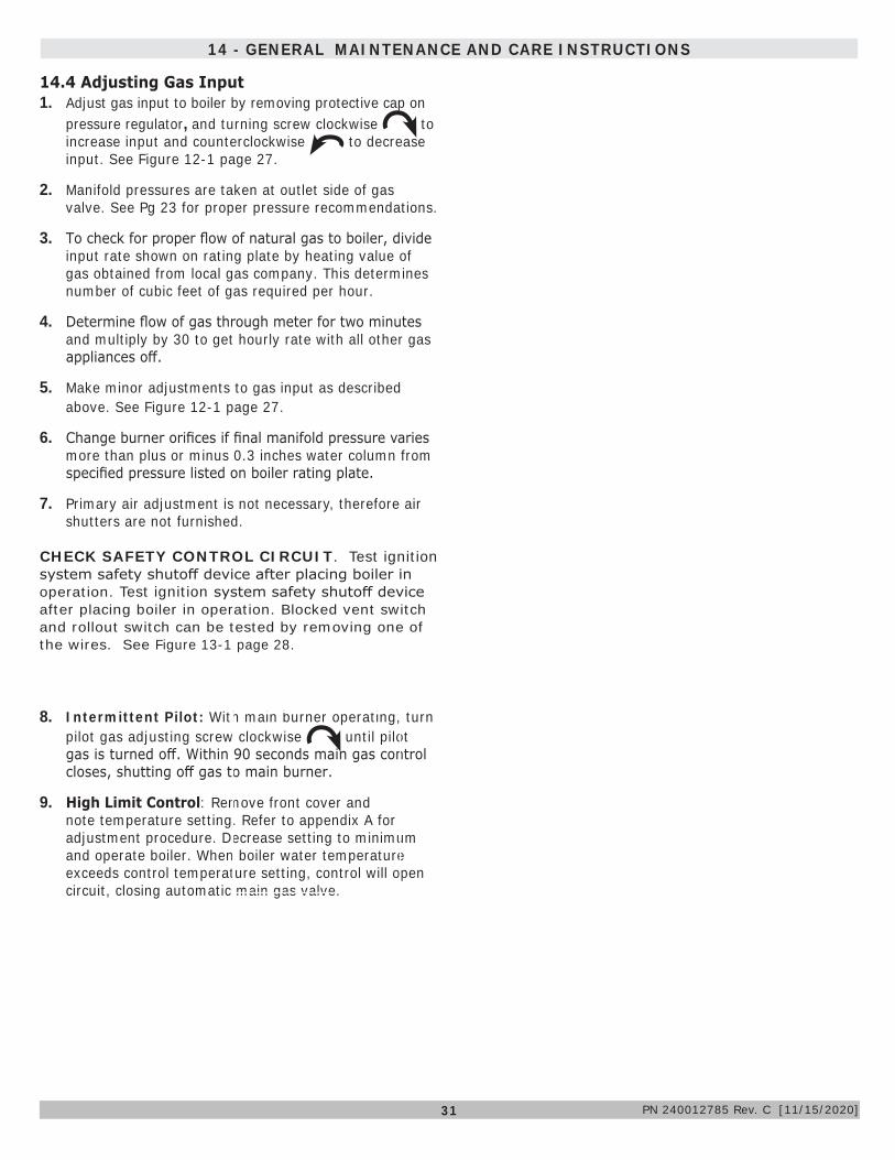
1. Adjust gas input to boiler by removing protective cap on pressure regulator, and turning screw clockwise to increase input and counterclockwise to decrease input. See Figure 12-1 page 27.
2. Manifold pressures are taken at outlet side of gas valve. See Pg 23 for proper pressure recommendations.
3. To check for proper flow of natural gas to boiler, divide input rate shown on rating plate by heating value of gas obtained from local gas company. This determines number of cubic feet of gas required per hour.
4. Determine flow of gas through meter for two minutes and multiply by 30 to get hourly rate with all other gas appliances off.
5. Make minor adjustments to gas input as described above. See Figure 12-1 page 27.
6. Change burner orifices if final manifold pressure varies more than plus or minus 0.3 inches water column from specified pressure listed on boiler rating plate.
7. Primary air adjustment is not necessary, therefore air shutters are not furnished.
CHECK SAFETY CONTROL CIRCUIT. Test ignition system safety shutoff device after placing boiler in operation. Test ignition system safety shutoff device after placing boiler in operation. Blocked vent switch and rollout switch can be tested by removing one of the wires. See Figure 13-1 page 28.
8. Intermittent Pilot: With main burner operating, turn pilot gas adjusting screw clockwise until pilot gas is turned off. Within 90 seconds main gas control closes, shutting off gas to main burner.
9. High Limit Control: Remove front cover and note temperature setting. Refer to appendix A for adjustment procedure. Decrease setting to minimum and operate boiler. When boiler water temperature exceeds control temperature setting, control will open circuit, closing automatic main gas valve.
14.4 Adjusting Gas Input
14 - GENERAL MAINTENANCE AND CARE INSTRUCTIONS
PN 240012785 Rev. C [11/15/2020]

32
15 - RATINGS AND CAPACITIES
PN 240012785 Rev. C [11/15/2020]
Table 15-1 - Ratings and Capacities
BoilerModel
Number of
Sections
(1)
Input Btu/hr
(1)
Heating Capacity Btu/hr
(2)
Net AHRI Rating Water
Btu/hr
AFUEFlue
Diameter Inches
(1)
High Altitude Input
Btu/hr
(3)
Recommended Air Cushion
Tank
MGB-060K 3 59,000 50,000 43,000 84.0 4 53,100 15MGB-095K 4 92,500 78,000 68,000 84.0 5 83,200 30
MGB-120K 5 120,000 101,000 88,000 84.0 6 108,000 30MGB-150K 6 149,000 125,000 109,000 84.0 6 134,100 30MGB-175K 7 175,000 147,000 128,000 84.0 7 157,500 30MGB-205K 8 205,000 172,000 150,000 84.0 7 184,500 30MGB-235K 9 235,000 197,000 171,000 84.0 7 211,500 30
EXPLANATORY NOTES-- All boilers are design certified for installation on noncombustible floor.-- Recommended chimney height 20 feet. In special cases where conditions permit, chimney height may be
reduced to 10 feet. Refer to the latest revision of National Fuel Gas Code ANSI Z223.13/NFPA 54 part 11.-- Electric service to be 120 Volts, 15 Amps, 60 Hz.-- The MEA number for the this boiler is 19-79-E.
(1) Input rating for sea level to 2,000 ft. (610m) above sea level.United States, over 2000 ft (610m) above sea level. Reduce input rate 4% for every 1000 ft (304m) above sealevel.Canada, 2000 ft (610m) to 4500 (1350m) above sea level reduce input per table. Over 4500 ft (1350m) above sealevel. Contact Provincial authority having jurisdiction.
(2) Net AHRI Water Ratings shown based on piping and pickup allowance of 1.15. Consult manufacturer before selectingboiler for installations having unusual piping and pickup requirements, such as intermittent system operation,extensive piping systems, etc.For forced hot water systems where boiler and all piping within area to be heated, boiler may be selected on basis ofits heating capacity.
(3) Tank sized for non-ferrous baseboard or radiant panel systems. Increase size for cast iron baseboard andradiation.
STANDARD EQUIPMENT: Boiler Jacket, Cast Iron Boiler Battery, High Limit Control, Intermittent Electric Ignition Pilot System, Vent Damper Relay, Main Gas Burners, Gas Control (Includes Automatic Gas Valve, Intermittent Pilot, Safety Shutoff, Pilot Flow Adjustment, Pilot Filter), A.S.M.E. Relief Valve, Drain Valve, Spill Switch, Rollout Switch, Automatic Vent Damper, Wiring Harness, Safety Pilot.

33
APPENDIX A - CONTROL FUNCTION
ECONOMY Target When the Economy feature is active, the Fuel Smart HydroStat continually sets target temperatures below the high limit setting to maximize fuel efficiency. When the boiler water reaches the target temperature, the LED illuminates and the burner will shut down. The boiler water will continue to circulate and heat the house as long as the thermostat call continues. The LED will stay lit until the boiler temperature drops below the differential set point at which point the boiler will be allowed to fire again. See Differential explanation on page 6 of Hydrolevel Manual. NOTE: This LED illuminates regularly during normal boiler operation
TEST/SETTINGS ButtonTo Test Low Water Cut-Off: Press and hold the Test/Settings button for 5 seconds. The display will read LCO. LWCO TEST LCO The red Low Water light should illuminate and the burner circuit (B1 and B2) should de-energize. NOTE: The control must be installed with a Hydrolevel Electro-Well for low water cut-off functionality (see page 2 of Hydrolevel manual for more details).
To View Current Settings: Press and release the Test/Settings Button in short intervals to sequentially display the following settings: HIGH LIMIT SETTING HL
LOW LIMIT SETTING LL
ECONOMY SETTING ECO
CURRENT TARGET TEMPERATURE 000The display will return to boiler temperature (default) if Test/Settings Button in not pressed for 5 seconds.
TEMP ACTIVE Indicates the Fuel Smart HydroStat control is powered and the temperature function is active.
TEMP HI TEMP Illuminates when the boiler watertemperature reaches the high limit setting. It will remain lit until the water temperature falls 10°. The Fuel SmartHydroStat prevents burner operation while this LED is on. See Differential explanation on page 6 of Hydrolevel Manual.
LWCO ACTIVE Indicates the low water cut-off (LWCO) function of the Fuel Smart HydroStat is active. When the control is installed with a Hydrolevel Electro-Well, this LED will be on at all times when the control is powered.IMPORTANT: If the control is installed with a well other than the Electro-Well, this LED will not illuminate indicating the control is not providing low water cut-off functionality.
LWCO LOW WATER Indicates the boiler is in a low water condition. The HydroStat control will prevent burner operation during this condition. If the LOW WATER light is blinking, the control has been programmed to provide lockout protection in the event a low water condition is detected. (see Manual Reset Low Water Cut-Off on page 8 of Hydrolevel manual). Pressing the TEST/SETTINGS button will reset the control.IMPORTANT: The system must be checked by a qualified heating professional prior to resuming operation.
ECONOMY ACTIVE Indicates the Thermal Targeting function is active and the Fuel Smart HydroStat will reduce boiler temperature to conserve fuel. The Economy feature is activated using the ECONOMY dial.
WARNINGBurn and scald hazard. Do not add water until boiler has fully cooled. Failure to follow these instructions could result in death or serious injury.
!
7
1
2
3
4
6
5
8 DAMPER POWER LEDIndicates the control is energizing the vent damper. For applications where the vent damper is not plugged into the HydroStat, the LED indicates the burner circuit (B1 - B2) is powered. LED will blink when power is sent to the Vent Damper and will turn solid when power returns from the end switch.
PN 240012785 Rev. C [11/15/2020]

34
A-1. Intermittent PilotIgnition System Checks
STEP 1: Check ignition cable.a. Verify ignition cable does not make contact with
metal surfaces.b. Verify only factory supplied Ignition cable (or
approved replacement) is used.c. Verify connections to ignition module and igniter or
igniter-sensor are clean and tight.d. Verify ignition cable provides good electrical
continuity.
STEP 2:Verify ignition system grounding. Nuisance shutdowns are often caused by poor or erratic grounding.Common ground is required for module and pilot burner/igniter sensor.
‒ Check for good metal-to-metal contact between pilot burner bracket and the main burner.
‒ Check ground lead from GND (BURNER) terminal on module to pilot burner. Verify connections are clean and tight. If wire is damaged or deteriorated, replace with No. 14-18 gauge, moisture-resistant, thermoplastic insulated wire with 105°C [221°F] minimum rating.
‒ Check ceramic flame rod insulator for cracks or evidence of exposure to extreme heat, which can permit leakage to ground. Replace pilot burner/igniter sensor and provide shield if necessary.
‒ If flame rod or bracket is bent out of position, restore to correct position.
If this LED is blinking and the burner is not firing:Make sure the plug connection (or jumper, on boilers where vent damper plug is not used) is secure.Make sure the plug connection at the vent damper end is secure and oriented correctly.Make sure damper motor turns.Verify the damper end switch has closed
DANGERCarbon Monoxide Hazard: If the burner fires when the vent damper is not fully opened or there is any other blockage in the flue, dangerous flueproducts, such as carbon monoxide, will escape into the living space causing severe personal injury or death. The flue as well as the vent damper must be checked for proper operation before allowing the system to operate.
!
Circ Delay LEDThe blue “circ delay” LED lights to indicate the heating circulator (terminal C1) is being held off. To minimize condensation on the boiler heat exchanger and in the flue due to low water temperature, the circulator is not energized until the boiler water temperature reaches 125°F. At that point, the circulator will be powered on and the LED will turn off. If the boiler water temperature falls below 115°F the circulator will turn off again and the LED will illuminate until the temperature reaches 125°F again.
9
APPENDIX A - CONTROL FUNCTION
PN 240012785 Rev. C [11/15/2020]
35
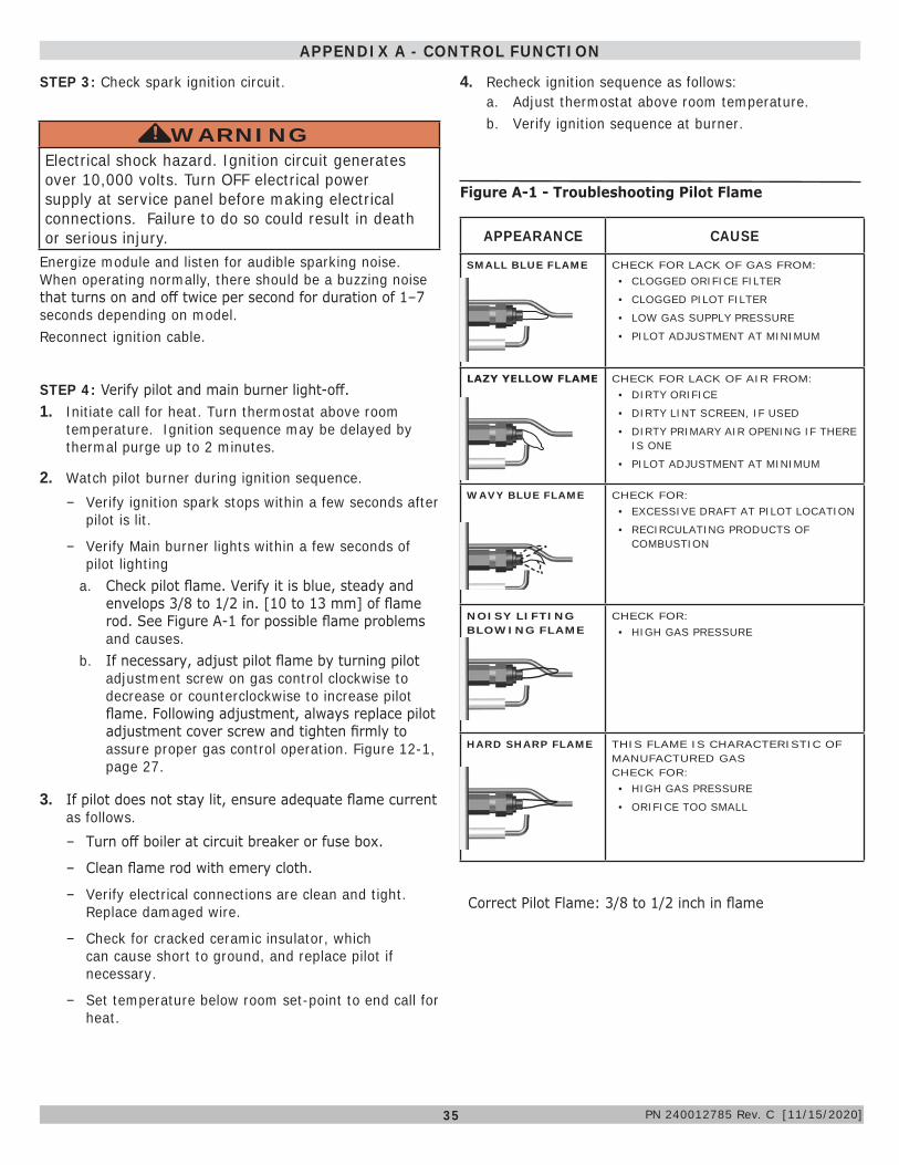
APPEARANCE CAUSE
SMALL BLUE FLAME CHECK FOR LACK OF GAS FROM:• CLOGGED ORIFICE FILTER
• CLOGGED PILOT FILTER
• LOW GAS SUPPLY PRESSURE
• PILOT ADJUSTMENT AT MINIMUM
LAZY YELLOW FLAME CHECK FOR LACK OF AIR FROM:• DIRTY ORIFICE
• DIRTY LINT SCREEN, IF USED
• DIRTY PRIMARY AIR OPENING IF THERE IS ONE
• PILOT ADJUSTMENT AT MINIMUM
WAVY BLUE FLAME CHECK FOR:• EXCESSIVE DRAFT AT PILOT LOCATION
• RECIRCULATING PRODUCTS OF COMBUSTION
NOISY LIFTING BLOWING FLAME
CHECK FOR:• HIGH GAS PRESSURE
HARD SHARP FLAME THIS FLAME IS CHARACTERISTIC OF MANUFACTURED GAS CHECK FOR:• HIGH GAS PRESSURE
• ORIFICE TOO SMALL
Figure A-1 - Troubleshooting Pilot Flame
Correct Pilot Flame: 3/8 to 1/2 inch in flame
STEP 3: Check spark ignition circuit.
WARNINGElectrical shock hazard. Ignition circuit generates over 10,000 volts. Turn OFF electrical power supply at service panel before making electrical connections. Failure to do so could result in death or serious injury.
!
Energize module and listen for audible sparking noise. When operating normally, there should be a buzzing noise that turns on and off twice per second for duration of 1–7 seconds depending on model.Reconnect ignition cable.
STEP 4: Verify pilot and main burner light-off.1. Initiate call for heat. Turn thermostat above room
temperature. Ignition sequence may be delayed by thermal purge up to 2 minutes.
2. Watch pilot burner during ignition sequence. ‒ Verify ignition spark stops within a few seconds after
pilot is lit.
‒ Verify Main burner lights within a few seconds of pilot lighting
a. Check pilot flame. Verify it is blue, steady and envelops 3/8 to 1/2 in. [10 to 13 mm] of flame rod. See Figure A-1 for possible flame problems and causes.
b. If necessary, adjust pilot flame by turning pilot adjustment screw on gas control clockwise to decrease or counterclockwise to increase pilot flame. Following adjustment, always replace pilot adjustment cover screw and tighten firmly to assure proper gas control operation. Figure 12-1, page 27.
3. If pilot does not stay lit, ensure adequate flame current as follows. ‒ Turn off boiler at circuit breaker or fuse box.
‒ Clean flame rod with emery cloth.
‒ Verify electrical connections are clean and tight. Replace damaged wire.
‒ Check for cracked ceramic insulator, which can cause short to ground, and replace pilot if necessary.
‒ Set temperature below room set-point to end call for heat.
4. Recheck ignition sequence as follows:a. Adjust thermostat above room temperature.b. Verify ignition sequence at burner.
APPENDIX A - CONTROL FUNCTION
PN 240012785 Rev. C [11/15/2020]

36
1. Verify only boiler is serviced by Vent Damper. Figure 2.
2. Clearance of 6 inches (152 mm) between Vent Damper and combustible material shall be maintained. Allow additional clearance for service of Vent Damper.
3. Vent Damper shall be in the open position when appliance main burners are operating.
4. Vent Damper position indicator must be in visible location following installation.
APPENDIX B - VENT DAMPER INSTALLATION
B.1 Damper InstallationFollow Damper installation instructions provided with damper. See Figure 1a & 1b.
Figure 1a - Horizontal Installations
Figure 2 - Alternate Vent Damper Installation
Check vent damper and all flue product carrying areas of boiler annually for deterioration from corrosion or other sources. Contact your service agent for repairs.
Check Vent Damper Operation as follows:1. When boiler is off, check vent damper position
indicator points to closed position. See Figure 3.2. Turn thermostat or controller up to call for heat and
check vent damper indicator points to open position See Figure 3.
3. Turn thermostat or controller down again and check damper position indicator returns to closed position.
4. Return thermostat to desired position.5. Place vent damper in open position to permit burner
operation by using “HOLD DAMPER OPEN” switch, located on damper controller.
6. Thermostat controls burner firing as before, while damper remains open.
7. DO NOT turn damper open manually, motor damage will result.
8. Set switch to “AUTOMATIC OPERATION” to close vent damper during burner off cycle.
9. For further information, and for vent damper troubleshooting guide, refer to manual packaged with vent damper.
Flue Gas
Flue Gas Flow
OPEN
CLOSED
ROTATIO
N
CLOSED
OPEN
ROTATIO
N
Damper Closed Damper Open
Open and Closed Positions Shown
B.2 Vent Damper
WARNINGAsphyxiation, burn hazard. Improper operation of vent damper may result in serious injury or death due to fire or to asphyxiation from poisonous gases such as carbon monoxide which is odorless and invisible.
!
Figure 3 - Vent Damper Position Indicator
Do Not Install Here
Do not install Vent Damper within 6" (152mm) of combustible material
Install Damper Here
Water Heater
ChimneyBoiler
To Boiler Vent Damper To Chimney
NO
NO
YES YES
Flow
Install vent damper with actuator to sides of vent only. Do not mount above or below vent
To Chimney
Vent Damper
To Boiler
Actuator may be installed in any
position
Flow
Figure B-1b - Vertical Installations
PN 240012785 Rev. C [11/15/2020]
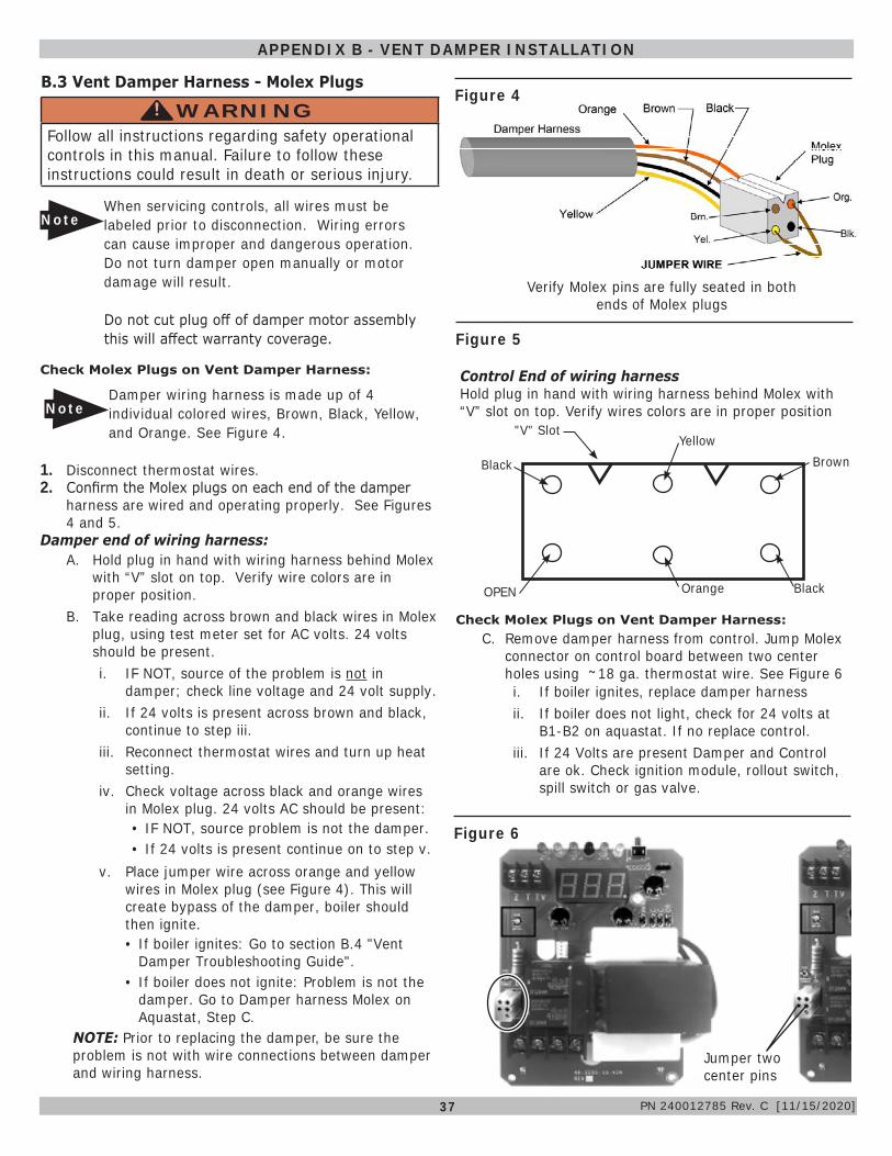
37
Figure 1a - Horizontal Installations
Figure B-1b - Vertical Installations
APPENDIX B - VENT DAMPER INSTALLATION
B.3 Vent Damper Harness - Molex Plugs
WARNINGFollow all instructions regarding safety operational controls in this manual. Failure to follow these instructions could result in death or serious injury.
!
Control End of wiring harness Hold plug in hand with wiring harness behind Molex with “V” slot on top. Verify wires colors are in proper position
OPEN
Black
"V" SlotYellow
Brown
Orange Black
1. Disconnect thermostat wires.2. Confirm the Molex plugs on each end of the damper
harness are wired and operating properly. See Figures 4 and 5.
Damper end of wiring harness:A. Hold plug in hand with wiring harness behind Molex
with “V” slot on top. Verify wire colors are in proper position.
B. Take reading across brown and black wires in Molex plug, using test meter set for AC volts. 24 volts should be present. i. IF NOT, source of the problem is not in
damper; check line voltage and 24 volt supply.ii. If 24 volts is present across brown and black,
continue to step iii.iii. Reconnect thermostat wires and turn up heat
setting.iv. Check voltage across black and orange wires
in Molex plug. 24 volts AC should be present:• IF NOT, source problem is not the damper.• If 24 volts is present continue on to step v.
v. Place jumper wire across orange and yellow wires in Molex plug (see Figure 4). This will create bypass of the damper, boiler should then ignite. • If boiler ignites: Go to section B.4 "Vent
Damper Troubleshooting Guide".• If boiler does not ignite: Problem is not the
damper. Go to Damper harness Molex on Aquastat, Step C.
NOTE: Prior to replacing the damper, be sure the problem is not with wire connections between damper and wiring harness.
NoteDamper wiring harness is made up of 4 individual colored wires, Brown, Black, Yellow, and Orange. See Figure 4.
Check Molex Plugs on Vent Damper Harness:
NoteWhen servicing controls, all wires must be labeled prior to disconnection. Wiring errors can cause improper and dangerous operation. Do not turn damper open manually or motor damage will result.
Do not cut plug off of damper motor assembly this will affect warranty coverage.
Figure 4
Verify Molex pins are fully seated in both ends of Molex plugs
Figure 5
C. Remove damper harness from control. Jump Molex connector on control board between two center holes using ~ 18 ga. thermostat wire. See Figure 6
Check Molex Plugs on Vent Damper Harness:
i. If boiler ignites, replace damper harnessii. If boiler does not light, check for 24 volts at
B1-B2 on aquastat. If no replace control. iii. If 24 Volts are present Damper and Control
are ok. Check ignition module, rollout switch, spill switch or gas valve.
Figure 6
Jumper two center pins
PN 240012785 Rev. C [11/15/2020]

38
B.4 Vent Damper Troubleshooting Guide
NoteWhen servicing controls, all wires must be labeled prior to disconnection. Wiring errors can cause improper and dangerous operation. Do not turn damper open manually or motor damage will result and affect warranty coverage, use the service switch.
Do not cut plug off of damper motor assembly this will affect warranty coverage.
Problem Possible Cause Recommended Solution
NO POWER Between 4 & 1
1. Off on limit (120VAC)2. Bad transformer3. Loose or broken connections4. Blown fuse or circuit breaker5. Disconnect switch off6. Harness not plugged into receptacle on aquastat
1. turn limit on2. Replace transformer3. Tighten, repair, or replace connection4. Replace fuse or reset circuit breaker5. Turn switch on6. Plug harness in
NO POWERBetween 4 & 2
POWERBetween 4 & 1
When calling for heat
1. Thermostat not calling for heat2. Burned out heat anticipator3. Loose or broken connections4. Off/On operating limit, pressure control or low water cut off5. Off/On blocked vent switch or flame roll out
1. Turn thermostat up to call for heat2. Replace thermostat3. Tighten, repair, or replace connection4. Turn operating limit, pressure control, or low water cutoff ON5. Reset or replace switch
POWERBetween 4 & 1Between 4 & 2DAMPER OPEN
1. Loose or broken connection2. Defective damper motor
1. Tighten, repair, or replace connection2. Replace damper motor assembly
Vent Damper Troubleshooting
WARNINGFollow all instructions regarding safety operational controls in this manual. Failure to follow these instructions could result in death or serious injury.
! 24 VAC Power Power ON Damper Position
4 & 1 All times Open or Closed4 & 2 Calling for Heat Open or Opening4 & 3 During combustion Damper Open
Normal Sequence of Operation
APPENDIX B - VENT DAMPER INSTALLATION
Orange
Black
Brown
Yellow
PN 240012785 Rev. C [11/15/2020]

39
NOTES
PN 240012785 Rev. C [11/15/2020]

IMPORTANT
In accordance with Section 325 (f) (3) of the Energy Policy and Conservation Act, this boiler is equipped with a feature that saves energy by reducing the boiler water temperature as the heating load decreases. This feature is equipped with an override which is provided primarily to
permit the use of an external energy management system that serves the same function.
THIS OVERRIDE MUST NOT BE USED UNLESS AT LEAST ONE OF THE FOLLOWING CONDITIONS IS TRUE:
• An external energy management system is installed that reduces the boiler water temperature as the heating load decreases.
• This boiler is not used for any space heating• This boiler is part of a modular or multiple boiler system having a total input of
300,000 BTU/hr or greater.• This boiler is equipped with a tankless coil.
All specifications subject to change without notice. ©2020 ECR International, Inc.
2201 Dwyer Avenue, Utica, NY 13501 Tel. 800 325-5479 www.ecrinternational.com
BDR THERMEA GROUP