design considerations for pulverized coal fired boilers … consideration for pc boilers illinois...
TRANSCRIPT

1 of 15
Design Considerations for Pulverized Coal Fired Boilers Combusting Illinois Basin Coals
Dianna Tickner Peabody Energy
St. Louis, Missouri
Reinhard W. Maier Power Systems Innovations & Investigations
Newington, Connecticut
Presented to Electric Power 2005 April 5 -7, 2005 Chicago, Illinois, U.S.A. Introduction Coals mined from the Illinois Basis produce a bituminous product with characteristics sufficiently different from eastern bituminous coals to warrant special considerations when designing for new boilers. The term Midwestern coals and Illinois basin coals are used interchangeably both in reference to coals found in Illinois, Indiana and Western Kentucky. These Midwestern coals on average are slightly more abrasive than the coal and the resulting ash for other U.S. bituminous coals with the exception to those mined in Utah. This characteristic may require examining the use of upgraded materials in the pulverizer and associated system components. Depending upon the ratio of survivability of quartz from coal to ash, special attention may be required to reduce flue gas velocities, particularly in the secondary superheater and reheater. The potential for severe slagging within the furnace is of particular concern. This is primarily due to generally lower ash fusion temperatures derived from a relatively high iron content, which is found in the form of pyrites. The pyrites in conjunction with substochiometric burner operation have been found to elevate waterwall corrosions rates significantly so as to require an alloy protection on furnace tubing in reducing zones of the furnace. The tendency to foul for Illinois can be from low to severe depending upon the particular product, a factor that will require designers to take all potential burns into consideration. Due to a combination of high alkali content and sulfur, boiler designers and operators need to be aware of the potential for liquid phase corrosion.

2 of 15
Abrasion and Wear The abrasiveness of a coal is a function of the mineral matter characteristics. An empirical expression was developed by Raask which allows for comparative analysis of coals and is presented by the equation:
AI = qc + 0.5pc + 0.2Ac Where qc, pc and Ac are respectively the relative weight contents of quartz, pyrites and ash found in the coal sample. When reviewing the information on the analysis of coals as presented in standard industry commercial practice, it is rare to find reports defining quartz. On the other hand, pyrites are frequently identified, and specification sheets always indicate the quantity of ash. In order to compensate for the lack of data, estimates for quartz and pyrites can be prepared with reasonable accuracy based upon formulas employing the reported chemical analysis for silica SiO2, alumina Al2O3 and sulfur S. The quantity of quartz in coal can then be determined by the expression:
qc = 0.01Ac(SiO2 – 1.5 Al2O3) Pyrites in coal are estimated by:
pc = 1.3(S-0.3) These equations can be used as reasonable substitutes for laboratory data in the abrasion index equation. Raask categorized the results of the abrasion index equation into four levels of abrasiveness as is shown in Table 1. Table1 Abrasion Index Classification
Abrasion Index Category
< 4 Slightly (Low) abrasive 4 -8 Moderately abrasive 8 -12 Highly abrasive >12 Exceptionally abrasive
In order to obtain a perspective on the abrasive quality of Illinois coals, a comparison to other U.S. bituminous coals and the national average of all coals is instructive as is shown in Table 2. The data reveals that Illinois coals, on average, are slightly more abrasive than other domestic coals. The principal reason for this higher abrasiveness, for comparable ash, appears to be the result of the relatively higher pyrite content found in the coals of the Illinois basin. The ash content of the coal, due to the quartz therein, has a linear increasing relationship with abrasion as the ash content of the coal rises. Figure 1 demonstrates how ash content impacts the coal’s abrasiveness.
Figure 1 Increase in Abrasion Index with increasing ash
0
2
4
6
8
10
12
14
0% 5% 10% 15% 20% 25% 30%
Ash Content of Coal
Abr
asio
n In
dex
Severe
Low

3 of 15
Table 2 Representative Abrasion Indices of U.S. bituminous coals
Location Ash Content (%)
Abrasion Index
Abrasive Category
Illinois Low Ash 9.7 5.7 Moderate
Medium Ash 14.3 7.4 Moderate Kentucky
Low Ash 8.4 3.6 Low Medium Ash 13.5 7.4 Moderate
Pennsylvania Low Ash 7.8 3.2 Low
Medium Ash 13.9 6.0 Moderate West Virginia
Low Ash 8.2 3.2 Low Medium Ash 14.5 4.9 Moderate
National Average - All Coals Clean (<5%) 3.9 1.2 Low
Low (5-12%) 8.4 3.6 Low Medium (12-18%) 14.1 5.9 Moderate
High (>18%) 25.6 9.5 High As indicated, the abrasiveness of coals from any given region presented are based upon an average quality. Minerals such as quartz and pyrites can vary significantly within a given seam as is demonstrated in Figures 2 and 3 for Illinois seam 6 coal. Consequently any consideration for the abrasive quality of the coal should be based upon the product from a specific mine. Figure 2 Variation of Quartz Herrin (No. 6) Figure 3 Variation of Pyrites in Herrin No. 6
Within the Illinois basin, seam to seam variations exist relative to the quantity of quartz and pyrites. These were investigated by Rao and Gluskoter and the average data is used to develop an Abrasion index for each seam in Table 3.

4 of 15
Table 3 Quartz and Pyrite Contents of Illinois Coals
Coal Member Quartz
(%) In Ash
Quartz (%)
In Coal
Pyrites (%)
In Ash
Pyrites (%)
In Coal
Low Temp Ash
Abrasion Index
Danville ( No. 7) 23.00 2.85 16.50 2.04 12.37 6.34 Herrin ( No. 6) 15.12 2.35 20.68 3.21 15.51 7.05 Springfield (No. 5) 18.36 2.84 24.93 3.86 15.47 7.86 Summum (No. 4) 16.32 2.50 21.55 3.30 15.33 7.22 Colchester (No. 2) 8.75 1.26 38.25 5.49 14.35 6.87 Murphysboro (No. 1) 6.75 0.99 39.25 5.79 14.74 6.84
When specifying transport, storage and milling systems for Illinois coals of moderate ash content additional design considerations relative to wear may not be economically justifiable. However, as the ash content of any coal increases, so does the required total coal throughput in order to maintain a constant heat input into the steam generator. This increased fuel flow will result in increased wear as a result of the both the abrasiveness and the total quantity of coal. With higher ash fuels, particular attention needs to be paid to material selection and thicknesses at points of transfer and in hoppers and silos. The locations in the coal process flow of greatest wear and therefore requiring the most maintenance are:
• Breaker (were installed to meet mill specifications) • Transfer points • Silos • Pulverizers • Coal piping
For pulverizers, wear can be directly related to the total quantity of quartz and pyrites as demonstrated by Donnais and shown in Figure 4. Using a Pittsburg 8 seam coal as the baseline in the Donnais formula, and comparing this to an Illinois coal of comparable ash content, the Illinois coal will produce a wear rate approximately 70% higher than the baseline Pittsburg 8 coal. The difference is primarily due to the pyrite content. Increasing the ash content will result in corresponding increases in quartz content producing further increases in pulverizer wear rate.
Figure 4 Roll Wear versus Quartz & Pyrite Content
y = 0.3638x2 - 0.0584x + 3.1808
0
5
10
15
20
25
30
35
0 2 4 6 8 10
x = 4 x quartz + pyrites
mic
rom
eter
wea
r per
100
0 to
ns c
oal
The quantity of quartz and pyrites from a raw Midwestern coal was noted in the studies by Pollack wherein bowl mill residue was examined in order to determine the quantity of higher sink fraction material, mostly pyrites, retained in the mill as a result of centrifugal classification within the mill. The work was performed as part of slagging and fouling investigations.

5 of 15
Figure 5 Mill Bowl Residue
Wear of boiler pressure parts, particularly those elements located in lower temperature regions such as the primary superheater, primary reheater and economizer is related to the quantity of quartz in the fly ash and the velocity of the flue gases. The survival of quartz in the combustion process can be directly related to pulverized coal fineness, flame temperature, unburned carbon and furnace retention time. Finer grinding and classification in the pulverizer tends to reduce quartz survival, while staged firing, substochiometric conditions in the burner zone, for NOx control will increase the survival factor for quartz. In order to quantify fly ash erosion, Raask developed an index analogous to the abrasion index for coal. The fly ash erosion index recognizes that wear on boiler pressure parts is primarily due to the fly ash fraction greater that 45 µm. The relative coarseness of flyash can be graded into three categories:
• Fine fly is ash having 15% > 45µm fraction • Coarse fly is ash having 30% >45µm fraction • Exceptionally coarse fly is ash having 50% >45 µm fraction
The fly ash erosion index is presented below where x1 is the fly ash fraction > 45µm :
Ia = 0.44 x1 (SiO2 – 1.5 Al2O3) + 0.18 (SiO2 – 1.5 Al2O3) + 0.35 x1 + 0.14
Using the fly ash erosion index as the basis Raask expands the analysis to define a maximum permissible velocity based upon an erosion rate of 50 nanometers per hour or 15.2 mils per 10,000 hours of operation. Table 4 is presented to demonstrate the comparative ash erosion potential with selected U.S. coals.
Table 4 Ash Erosion Index for Selected U.S. Coals
Coal / Utility
Quartz in Ash
>45µ Fraction
Ash Erosion Index
E. Kentucky / Big Sandy 4.6 31 0.28 W. Kentucky / Tanners Creek 6.1 19 0.24 Indiana / Stout 6.3 24 0.26 Pennsylvania / Homer City 5.6 22 0.25 Arizona / Mohave 10.0 32 0.32 Utah Power & Light 15.4 85 0.61
Assuming a constant quartz survival rate of 24% for Illinois basin coals and applying the Raask formulation to a series of Illinois Basin coals mined in both Illinois and Indiana, the fly ash erosion index is found to be maintained at a constant moderate level as shown in Table 5:

6 of 15
Table 5 Coal & Ash Erosion of Selected Illinois & Indiana Coals
Raask further expanded the fly ash abrasion index formula by including the flue gas temperature, and the carbon content of the coal in order to ascertain the maximum backpass velocity for a desired wear rate. This equation is presented as:
Log vm = 0.343 + 0.303 (log wr – log Ip) Where wr = wear rate and Ip = erosion wear propensity. Applying this formula for selected Illinois basin coals, including those mined in Indiana and factoring standardized flue gas temperatures, we have the result outlined in Table 6. Table 6 Estimates of Maximum Velocities for Select Illinois & Indiana Coals @ Varying Temperatures
Wear Rate = 0.5 0.5 0.5 Micro inches per hour Flue Gas = 2,000 1,500 1,000 Deg F
Coal "A" 35.6 33.2 30.4 Feet / sec Coal "B" 33.8 31.6 28.9 Feet / sec Coal "C" 33.7 31.5 28.8 Feet / sec Coal "D" 50.0 46.7 42.7 Feet / sec Coal "E" 46.2 43.1 39.5 Feet / sec Coal "F" 49.5 46.2 42.3 Feet / sec Coal "G" 51.6 48.2 44.1 Feet / sec
Furnace Slagging Slag according to Hensel is defined as the fused deposits or resolidified molten material that forms primarily on furnace walls and other surfaces exposed predominantly to radiant heat or excessively high gas temperatures. The study of coal slags provides boiler designers with the tools to evaluate furnace absorption and determine gas temperatures. A key consideration in the design of any furnace is the volumetric and plan area sizing in order to achieve desired limits set for both the horizontal and vertical furnace exit gas temperatures (HFEGT & VFEGT). The primary object is to prevent excessive fouling on platen and pendant surfaces. Critical to the process is the estimating of the amount of slagging which will take place and the effectiveness of removal with sootblowing. Primarily due to the high iron content of Illinois basin coals, ash fusion temperatures are often below 2,100 deg R (oxidizing). As discussed by Pollock the major cause of slagging for Midwestern coals is the selective deposition of segregated, low melting iron enriched constituents. Form of the iron in the slag is important. Fully oxidized Fe2O3 melts at higher temperature than iron pyrites, FeS2, which has a melting point of 2,140 deg F. Reduced iron, FeO acts as a flux with silica to form a FeSiO2 with a melting point of 2,096 deg F. With burner zone temperatures approximately 3,000 deg F, sufficient temperature exists for these compounds to melt.
Index or Classification Coal A Coal B Coal C Coal D Coal E Coal F Coal G
Coal Abrasion Classification: severe severe severe medium medium medium medium Coal Wear Propensity Classification: high high high medium medium medium low Coal Wear Propensity Index: 11.0 12.6 13.3 4.2 5.3 4.0 3.0 Fly Ash Erosion Index: 0.28 0.28 0.29 0.29 0.29 0.26 0.27 Fly Ash Erosion Index Level: medium medium medium medium medium medium medium

7 of 15
However Pollock further indicates that slagging potential is poorly correlated relative to the presence of Fe2O3 in the ash. Gravity fractionation data of 2.9 sink fraction is a stronger predictor of slagging potential. An analysis of iron in 2.9 sink fraction compared to other U.S. coals reveals that Midwestern or Illinois basin coals have a severe slagging potential as shown in Table 7 and Figure 6. Table 7 Ash Slagging Potential of U.S. Coals as a Function of Iron in 2.9 Sink Fraction
Geographical Region
Ash Content
Ash Fusion (Red) I.D.
Ash Fusion (Red) F.T
Fe2O3 in Ash %
Fe2O3 in 2.9 sink Fraction
Slagging Potential
Slagging Potential
Classification
Midwest 13.0 2010 2390 22.7 85 9.7 Severe Montana 11.7 2040 2310 8.2 75 9.5 Severe Penn 16.8 2110 2640 19.0 79 9.2 Severe W. Kentucky 13.5 1980 2270 27.2 78 8.8 Severe Illinois 7.7 2330 2570 4.0 74 8.4 Severe Midwest 13.4 1940 2250 22.9 72 8.3 Severe Ohio 15.4 1970 2370 22.6 62 6.6 High Penn. 17.1 2310 2700 9.5 59 6.5 High Illinois 12.3 2050 2140 13.0 59 6.5 High Penn. 16.6 2360 2700 12.7 60 6.3 High Illinois 10.5 2080 2300 15.9 57 6.1 High Penn. 16.6 2570 2700 9.8 58 5.2 High Ky. & Tenn. 15.7 2700 2700 4.2 50 4.5 Moderate Arizona 13.3 2570 2700 5.8 43 3.1 Moderate Virginia 13.9 2350 2700 8.3 40 1.4 Low
Figure 6 Ash Slagging Potential of U.S. Coals as a Function of Iron in 2.9 Sink Fraction The lower ash fusion temperatures found in Midwestern coals are capable of producing strongly bonded slags. Regan indicates that if ash particles ash particles arrive on heat absorbing surfaces and have been subject to temperatures higher than the softening temperature for sufficient time to become plastic or liquid, the resulting deposit is apt to be a fused mass and difficult to remove. The concern is that these slag

8 of 15
deposits can sufficiently alter the heat transfer characteristics to vary the flue gas temperature leaving the furnace in the range of 200 deg F. Compounding the matter according to Hensel is that the chloride deposits in Midwestern coals result in a more dense tenacious deposit that builds up at a slower rate than high alkali coals. Figure 7 Distribution of Chlorine in Herrin No. 6 Coal In addition to examining the iron content of a coal other useful indices have been developed to evaluate slagging potential. These can generally be grouped as either a factor relating to viscosity or the relationship of basic and acidic oxides in the ash. The first set presented in Table 8 are nondimensional in that the slagging potential of the coal does not bear any relationship to boiler geometry. This failure to link to steam generator physical characteristics requires the boiler designer to examine other considerations. Table 8 Bituminous Non Dimensional Slagging Indices
One well recognized design factor is the net heat input per plan area, NHIPA. Lower NHIPA boilers generally also have larger furnace volumes and corresponding larger furnace areas. These larger furnaces compensate for the heat absorption lost due to higher slag buildups. For lower quality coals an approximate
Index Dependent Variables Watt & Fereday Silica Alumina Iron Lime Viscosity T250 Correlations Temperature @
250 poise
Viscosity Index (Rvs) Silica Alumina Iron Lime Halfinger Cleanability Index
Ash Coal HHV Softening Temp H=W
Base to Acid Ratio Iron Lime Magnesia Potassium Sodium
Silica Alumina Titania
Attig & Duzy Base Acid Sulfur Silica Factor Silica Iron Lime Magnesia
9 of 15
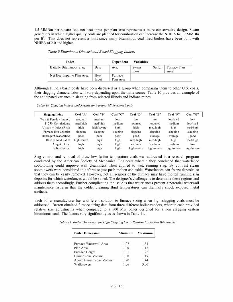
1.5 MMBtu per square foot net heat input per plan area represents a more conservative design. Steam generators in which higher quality coals are planned for combustion can increase the NHIPA to 1.7 MMBtu per ft2. This does not represent a limit since many bituminous coal fired boilers have been built with NHIPA of 2.0 and higher.
Table 9 Bituminous Dimensional Based Slagging Indices
Index Dependent Variables
Battelle Bituminous Slag Base Acid Steam Flow
Sulfur Furnace Plan Area
Net Heat Input to Plan Area Heat Input
Furnace Plan Area
Although Illinois basin coals have been discussed as a group when comparing them to other U.S. coals, their slagging characteristics will vary depending upon the mine source. Table 10 provides an example of the anticipated variance in slagging from selected Illinois and Indiana mines. Table 10 Slagging indices and Results for Various Midwestern Coals
Slagging Index Coal "A" Coal "B" Coal "C" Coal "D" Coal "E" Coal "F" Coal "G" Watt & Fereday Index : medium medium low low low low/med low
T_250 Correlations: med/high med/high medium low/med low/med medium low/med Viscosity Index (Rvs): high high/severe high high med/high high med/high Furnace Exit Criteria: slagging slagging slagging slagging slagging slagging slagging
Halfinger Cleanability: poor poor poor good average average good Base to Acid Ratio: high/severe high high med/high med/high high med/high
Attig & Duzy: high high high medium medium medium low Silica Factor: high high high high/severe high/severe high/severe high/severe
Slag control and removal of these low fusion temperature coals was addressed in a research program conducted by the American Society of Mechanical Engineers wherein they concluded that waterlance sootblowing could improve wall cleanliness when applied to wet, running slag. By contrast steam sootblowers were considered to deform or just push molten ash aside. Waterlances can freeze deposits so that they can be easily removed. However, not all regions of the furnace may have molten running slag deposits for which waterlances would be suited. The designer’s challenge is to determine these regions and address them accordingly. Further complicating the issue is that waterlances present a potential waterwall maintenance issue in that the colder cleaning fluid temperatures can thermally shock exposed metal surfaces. Each boiler manufacturer has a different solution to furnace sizing when high slagging coals must be addressed. Barrett obtained furnace sizing data from three different boiler vendors, wherein each provided relative size adjustments when compared to a 500 Mw boiler designed for a non slagging eastern bituminous coal. The factors vary significantly as as shown in Table 11. Table 11_Boiler Dimension for High Slagging Coals Relative to Eastern Bituminous
Boiler Dimension Minimum Maximum
Furnace Waterwall Area 1.07 1.34 Plan Area 1.00 1.16 Furnace Height 1.01 1.22 Burner Zone Volume 1.00 1.17 Above Burner Zone Volume 1.20 1.44 Wallblowers 1.06 3.00

10 of 15
Furnace Waterwall Corrosion Waterwall corrosion has always been a concern for the power industry. However in recent years, primarily with the wide spread application of low NOx burner systems, including staged combustion, the rate of corrosion of waterwalls has seen a dramatic increase. Kung & Bakker have postulated that as a result of reducing environments pyrites are partially converted to hydrogen sulfide by the reaction:
FeS2 + CO + H2O → FeS + H2S + CO2 Kung conducted extensive laboratory studies on the effect of H2S, temperature and chrome content of waterwall tubes to derive a corrosion rate given as:
CR = 3.2 x 10⁵ x exp(-15818/1.987 T) x (H2S)0.574 x 1/(%Cr + 10.5)1.234 +2.2 Where:
CR = Corrosion rate (mil / year) T = metal temperature in deg K H2S = H2S concentration in flue gas in ppm % Cr = weight % of Cr in steel
Using the formula a predicted corrosion rate for varying H2S concentrations was developed. Corrosion rates at tube metal temperatures of 850 deg F, which is typical for supercritical applications, is estimated to range from 10 to 20 mils per year. The relatively high quantity of pyrites found in Midwestern coals are expected to convert to high concentrations of H2S, particularly where staging is employed for low NOx control. Figure 8 provides an example of the potential corrosion for an unprotected waterwall. Figure 8 Example of Waterwall Corrosion from a Supercritical Boiler Several methods may be employed to control waterwall corrosion as discussed by J.C. Nava-Paz et al. These included:
a) Maintenance of burner nozzles to avoid flame impingement b) Close attention to coal fineness and distribution to prevent coarse particles from reaching
furnace walls c) Improved mixing and distribution of combustion air to reduce concentrations of SO3 and
pyrites near walls d) Waterwall tube coatings
Waterwall tube coatings to address corrosion loss include chromizing and Inconel cladding. In research work conducted by Plumley on a supercritical boiler significant arresting of corrosion was achieved as is demonstrated in Table 12.

11 of 15
Table 12 Waterwall Corrosion Experienced Over 2.5 Years on a Supercritical Test Panel
Waterwall Material
Corrosion rate in mils per year
Bare T-22 45 – 55 Inconel Clad 6 T-22 Chromized 7
By means of comparative analysis, using the Kung equation and assuming: H2S = 1,000 ppm Tube metal temperature = 850 deg F Material Chrome – Inconel = 50% Cr Results in annual corrosion rate of 4.1 mils which approximates the Plumley data. Convective Pass Fouling & Upper Furnace Slagging The term fouling is generally meant to apply to ash deposition in the convective sections of the boiler and for a pendant type unit these are shown in the darker shaded regions of Figure 9 Figure 9 Fouling Region of a Pendant Boiler A proper design objective is to have the ash arrive at a heat absorbing surface at temperature below the ash softening temperatures. However due to limitations on furnace sizing and surface considerations for pendant heat transfer surfaces, it is not always practical to follow the ash softening rule. Singer addresses this issue by relocating the point of contact. Where he defines the furnace outlet plane as the entrance to the closed-spaced convection surface; the latter being a non-platen surface on less than 12 inch horizontal centers. This plane is also referred to as the vertical furnace exit gas plane (VFEGT). In most designs the platen and final superheaters will be to subject to fouling due to ash exposure to flue gas temperatures ranging from 2,450 to 2,750 deg F at the horizontal furnace exit gas plane (HFEGT). The Illinois basin coals used for analysis in this paper ranged in softening temperature from 2,050 to 2,175 deg F, reducing, and 2,370 to 2,540 deg F oxidizing. These coal ashes will result in slag buildup on the platen and pendant surfaces. Consequently, designers should consider avoiding platen assemblies unless a means

12 of 15
is provided to remove slag buildup effectively. Compounding the slag buildup problem is that the rate of deposit buildup is a function of flue gas temperature, as is shown in Figure 10. Figure 10 Ash Deposit Buildup as a Function of Flue Gas Temperature Increased fouling is generally associated with sodium or alkalis present within the coal. Several relationships have been developed to define fouling potential based upon ash analysis. These are shown in Table 13. More sophisticated methods have been employed based upon mineral analysis obtained by computer controlled scanning electron microsopy, CCSEM. However, CCSEM as a commercial practice is not commonly utilized.
Table 13 Bituminous Fouling Indices
Index
Dependent Variables
Chlorine Factor: Chlorine Sodium Eastern Factor: Sodium Sodium - Potassium Factor: Sodium Potassium Sodium Equivalent Factor: Sodium Potassium Ash% Base to Acid - Sodium Adjusted: Base Acid Sodium Alkali Factor: Sodium Potassium Ash% Battelle Bituminous Fouling Index:
Sulfur Lime Steam Flow
EPRS
The fouling potential of Illinois basin coals can vary significantly depending upon the mine as is demonstrated in Table 14. This is principally due to a wide range of sodium content. The issue for the boiler designer is to insure sufficient assembly to assembly spacing to accommodate the worse case coal planned for the unit. Table 14 Fouling Indices and Results for Various Midwestern Coals
Fouling Index Coal "A"
Coal "B"
Coal "C"
Coal "D"
Coal "E"
Coal "F"
Coal "G"
Chlorine Factor: low low low low low low low
Sodium Eastern Factor: med/high medium low/med low med/high low/med high/severe Sodium - Potassium Factor: med/high low/med low low medium low high/severe Sodium Equivalent Factor: high/severe high/severe severe low low/med low low/med
Base to Acid - Sodium Adjusted: high medium low/med low med/high low/med high/severe
Alkali Factor: high/severe high/severe severe low low/med low low/med

13 of 15
A primary factor in the control of fouling is the spacing arrangement of tube assemblies. These fouling considerations need to be factored into the original design, since post construction modifications are difficult. Nanotechnology based coatings, currently under development, may correct fouling problems due to poor cleanability. Research for these applications is ongoing. Table 15 presents design options for assembly clearance based upon the fouling characteristic of the coal. Table 15 Transverse Clear Spacing
Flue Gas Temperature Clearance
High Low Non
Fouling Fouling Severe Fouling
Deg F Deg F inches inches inches
2,000 2,400 Platens 22 22 30 - 60 1,750 2,000 Platens 12 1,750 2,000 Pendant 7 20 - 32 1,450 1,750 Spaced 3 6 9 1,450 Spaced 2 3 4.5
800 Economizer Fin tube Bare tube Bare tube Liquid Phase Corrosion Not all coals have a potential for developing a corrosive ash. However, Illinois basin coals are considered to be corrosive at elevated temperatures due to a sufficiently high ratio of alkali metals and in combination with sulfur from SO3. The combination forms the alkali iron trisulfates Na3Fe(SO4)3 and K3Fe(SO4)3 which in a molten state are primarily responsible for metal loss in superheaters and reheaters. Because of the phenomenon of liquid phase corrosion boilers built to fire Illinois basin coals have been historically limited to steam outlet temperatures of 1,005 deg F in order to keep external tube metal temperatures sufficiently low to prevent the trisulfates from reaching the molten state. Some units built by Commonwealth Edison were designed to burn a Midwestern coal with a 1,050 deg F outlet steam conditions but subsequently were reduced due to unacceptable metal loss rates. Figure 11 demonstrates the structure of these deposits in relationship to steam temperatures. Figure 11 Tube deposits and internal steam temperature Reducing the rate of liquid phase corrosion from alkali iron trisulfates can take two different tacks. One school of thought involves the application of advanced alloys in area susceptible to attack. The rate of liquid phase corrosion is directly proportional to the deposit temperature and inversely proportional to the chrome content and to some extent the nickel content of the tubing material. Extensive research on tubing materials capable of withstanding corrosion under high tube stress design has been performed in order to provide materials for ultra supercritical cycles. A bell shaped curve of corrosion versus tube metal temperature demonstrates this relationship in Figure 12.
Effect of steam temperature on deposit structure.Effect of steam temperature on deposit structure.

14 of 15
Figure 12 Corrosion Rate for 16 & 18% Chrome Tubing vs. External Metal Temperature Recent and ongoing research indicates corrosion at peak temperatures could be reduced to within a band between 2.8 and 7 mils per year when employing 25% chrome materials. An alternate approach would be to reposition the final superheater and reheater such that these assemblies are in contact with lower flue gas temperatures. The concept being that cooler flue gases would not be as likely to produce a molten deposit and thereby reduce the corrosion process. This approach requires that the secondary superheater and reheater pendants be placed upstream of the finishing elements. The final superheater and reheater is then located further back in the backpass where they are exposed to cooler flue gases than they would otherwise if located in the radiant or initial convective zone. Figure 13 Finishing Superheater and Reheater Relocated in Reduced Gas Temperature Zone
0
2
4
6
8
10
12
14
16
18
20
950 1,050 1,150 1,250 1,350
Tube External Metal Temperature
Cor
rosi
on R
ate
in m
ils p
er y
ear
Final Superheater & Reheater

15 of 15
References
1. Erich Raask, “ Erosion Wear in Coal Utilization,” Hemisphere Publishing Corp, 1988
2. Erich Raask, “ Mineral Impurities in Coal Combustion,” Hemisphere Publishing Corp, 1985
3. W. H. Pollock, G. J Goetz, E. D. Park, “Advancing the Art of Boiler Design by Combining Experience and Advanced Coal Evaluation Techniques,” paper present at the American Power Conference, April 18 1983, Chicago, Illinois
4. John W. Regan, “Impact of Coal Characteristics on Boiler Design,” paper presented at the Coal
Technology 1982 Exhibition & Conference, December 7, 1982, Houston, Texas
5. R. P. Hensel. “Coal Combustion,” paper presented at Engineering Foundation Conference on Coal Preparation for Coal Conversion, August 10, 1975, Rindge, New Hampshire
6. S.C. Kung & W. T. Bakker, “Waterwall Corrosion in coal Fired Boilers – a New Cluprit: FeS,”
paper presented at the NACE Corrosion 2000 Conference, March 26, 2000, Orlando Florida
7. J.C. Nava-Paz et al, “Waterwall Corrosion Mechanisms in Coal Combustion Environments,” Materials at High Temperatures 19(3) p 127-137, 2002
8. ASME Research Committee on Corrosion and Deposits from Combustion Gas, “Expanded Use of
High-Sulfur, Low-Fusion Coal in Utility Boilers,” ASME Technical Publishing, October 2000
9. William T. Reid, “External corrosion and Deposits Boilers and Gas Turbines,” American Elsevier Publishing Company, New York, 1971
10. Arthur L. Plumley et al, “Alloys and Coatings to Reduce Waterwall Corrosion and Waterwall
Cracking in Boilers,” paper presented at EPRI Seminar Fossil Plant Retrofits for Improved Heat Rate and Availability, December 1, 1987, San Diego, California
11. S. J. Vecci et al, “Fuel and Ash Characterization and Its Effect on the Design of Industrial
Boilers,” paper presented to the American Power Conference, April 24, 1978, Chicago, Illinois
12. Joseph G. Singer, editor, “Combustion Fossil Power Systems,” Combustion Engineering, 1981
13. Richard W. Borio et al, “ Slagging and Fouling Properties of Coal Ash Deposits as Determined in a Laboratory Test Facility,” paper presented at the American Society of Mechanical Engineers Winter Annual Meeting, November 28, 1977, Atlanta, Georgia
14. Richard W. Borio et al, “ Developing a Coal Quality Expert: Combustion and Fireside
Performance Characterization Factors,” prepared for CQ, Inc. / U.S. Department of Energy under contract number: DE-FC22-90PC89663, April 1993
15. C. P. Roa & H. J. Gluskoter, “Occurrence and Distribution of Minerals in Illinois Coals,” Illinois
State Geological Survey Circular 476, 1973
16. R. E. Barrett, “Designing Boilers to Avoid Slagging, Fouling,” Power, February, 1990
17. EPRI TR-103438, “Superheater Corrosion: Filed Test Results,” prepared by Foster Wheeler Development Corporation, Livingston, NJ, November 1993