metropolis metamodel. copyright a. sangiovanni-vincentelli metropolis objects metropolis elements...
Post on 21-Dec-2015
220 views
TRANSCRIPT

Metropolis Metamodel

Copyright A. Sangiovanni-Vincentelli
Metropolis Objects
• Metropolis elements adhere to a “separation of concerns” point of view.
Proc1P1 P2
I1 I2Media1
QM1
Active ObjectsSequential Executing Thread
Passive ObjectsImplement Interface Services
Schedule access to resources and quantities
• Processes (Computation)
• Media (Communication)
• Quantity Managers (Coordination)

Copyright A. Sangiovanni-Vincentelli
Metro. Netlists and EventsProblem StatementApproachContribution
Proc1
P1
Media1 QM1
Scheduled Netlist Scheduling Netlist
GlobalTime
Metropolis Architectures are created via two netlists:• Scheduled – generate events1 for services in the scheduled netlist.• Scheduling – allow these events access to the services and annotate events with quantities.
I1
I2 1. E. Lee and A. Sangiovanni-Vincentelli, A Unified Framework for Comparing Models of Computation, IEEE Trans. on Computer Aided Design of Integrated Circuits and Systems, Vol. 17, N. 12, pg. 1217-1229, December 1998
Proc2
P2
Event1 – represents a transition in the action automata of an object. Can be annotated with any number of quantities. This allows performance estimation.
Related Work

Copyright A. Sangiovanni-Vincentelli
Key Modeling Concepts• An event is the fundamental concept in the
framework– Represents a transition in the action automata of an
object– An event is owned by the object that exports it– During simulation, generated events are termed as
event instances – Events can be annotated with any number of
quantities– Events can partially expose the state around them,
constraints can then reference or influence this state
• A service corresponds to a set of sequences of events– All elements in the set have a common begin event
and a common end event– A service may be parameterized with arguments
1. E. Lee and A. Sangiovanni-Vincentelli, A Unified Framework for Comparing Models of Computation, IEEE Trans. on Computer Aided Design of Integrated Circuits and Systems, Vol. 17, N. 12, pg. 1217-1229, December 1998

Copyright A. Sangiovanni-Vincentelli
Action Automata• Processes take actions.
– statements and some expressions, e.g.y = z+port.f();, z+port.f(), port.f(), i < 10, …
– only calls to media functions are observable actions
• An execution of a given netlist is a sequence of vectors of events.– event : the beginning of an action, e.g. B(port.f()), the end of an action, e.g. E(port.f()), or null N– the i-th component of a vector is an event of the i-th process
• An execution is legal if– it satisfies all coordination constraints, and– it is accepted by all action automata.

Copyright A. Sangiovanni-Vincentelli
Execution semanticsAction automaton:
– one for each action of each process• defines the set of sequences of events that can happen in
executing the action
– a transition corresponds to an event:• it may update shared memory variables:
– process and media member variables– values of actions-expressions
• it may have guards that depend on states of other action automata and memory variables
– each state has a self-loop transition with the null N event.
– all the automata have their alphabets in common:
• transitions must be taken together in different automata, if they correspond to the same event.

Copyright A. Sangiovanni-Vincentelli
Action Automata
Return
B y=x+1 B x+1 E x+1 E y=x+1y:=Vx+1
B x+1 E x+1 E y=x+1y:=any
* = write y* * *
B x+1 E x+1Vx+1 :=x+1
E x+1Vx+1 :=any
write x
y=x+
1
x+1
• y=x+1;
000
B y=x+1 B x+1 E x+1NN N E y=x+1
500
550
100
110
Vx+1yx

Copyright A. Sangiovanni-Vincentelli
Semantics summary• Processes run sequential code concurrently, each at its
own arbitrary pace.
• Read-Write and Write-Write hazards may cause unpredictable results– atomicity has to be explicitly specified.
• Progress may block at synchronization points– awaits– function calls and labels to which awaits or constraints refer.
• The legal behavior of a netlist is given by a set of sequences of event vectors.– multiple sequences reflect the non-determinism of the semantics:
concurrency, synchronization (awaits and constraints)

Metropolis Architecture Representation

Copyright A. Sangiovanni-Vincentelli
Architecture componentsAn architecture component specifies services, i.e.
• what it can do
• how much it costs

Meta-Model : Functional Netlist
process P{
port reader X;
port writer Y;
thread(){
while(true){
...
z = f(X.read());
Y.write(z);
}}}
medium M implements reader, writer{
int storage;
int n, space;
void write(int z){
await(space>0; this.writer ; this.writer)
n=1; space=0; storage=z;
}
word read(){ ... }
}
interface reader extends Port{
update int read();
eval int n();
}
interface writer extends Port{
update void write(int i);
eval int space();
}
MP1X Y P2X Y
Env1 Env2
MyFncNetlist

Meta-Model: Architecture Components
An architecture component specifies services, i.e.
• what it can do
• how much it costs
: interfaces
: quantities, annotation, logic of constraints
medium Bus implements BusMasterService …{
port BusArbiterService Arb;
port MemService Mem; …
update void busRead(String dest, int size) {
if(dest== … ) Mem.memRead(size);
[[Arb.request(B(thisthread, this.busRead));
GTime.request(B(thisthread, this.memRead),
BUSCLKCYCLE +
GTime.A(B(thisthread, this.busRead)));
]]
}
…
scheduler BusArbiter extends Quantity
implements BusArbiterService {
update void request(event e){ … }
update void resolve() { //schedule }
}
interface BusMasterService extends Port {
update void busRead(String dest, int size);
update void busWrite(String dest, int size);
}
interface BusArbiterService extends Port {
update void request(event e);
update void resolve();
}
BusArbiterBus

Copyright A. Sangiovanni-Vincentelli
Meta-model: quantities• The domain D of the quantity, e.g. real for the global time,
• The operations and relations on D, e.g. subtraction, <, =,
• The function from an event instance to an element of D,
• Axioms on the quantity, e.g.
the global time is non-decreasing in a sequence of vectors of any
feasible execution.class GTime extends Quantity { double t; double sub(double t2, double t1){...} double add(double t1, double t2){…} boolean equal(double t1, double t2){ ... } boolean less(double t1, double t2){ ... } double A(event e, int i){ ... } constraints{ forall(event e1, event e2, int i, int j): GXI.A(e1, i) == GXI.A(e2, j) -> equal(A(e1, i), A(e2, j))
&& GXI.A(e1, i) < GXI.A(e2, j) -> (less(A(e1, i), A(e2, j)) ||
equal(A(e1, i), A(e2. j)));}}

Copyright A. Sangiovanni-Vincentelli
Meta-model: architecture components
• This modeling mechanism is generic, independent of services and cost specified.
• Which levels of abstraction, what kind of quantities, what kind of cost constraints should be used to capture architecture components?– depends on applications: on-going research
Transaction: Services:
- fuzzy instruction set for SW, execute() for HW
- bounded FIFO (point-to-point)
Quantities:
- #reads, #writes, token size, context switches
Physical:
Services: full characterization
Quantities: time
CPU ASIC2ASIC1
Sw1 HwSw2
Sw I/F Channel I/F
Wrappers
Hw
Bus I/F
C-Ctl Channel Ctl
B-I/FCPU-IOs
e.g. PIBus 32b
e.g. OtherBus 64b...
C-Ctl
RTOS
Virtual BUS: Services:
- data decomposition/composition
- address (internal v.s. external)
Quantities: same as above, different weights

Copyright A. Sangiovanni-Vincentelli
Quantity resolutionThe 2-step approach to resolve quantities at each state of a
netlist being executed:1. quantity requests for each process Pi, for each event e that Pi can take, find all the
quantity constraints on e. In the meta-model, this is done by explicitly requesting quantity
annotations at the relevant events, i.e. Quantity.request(event, requested quantities).
2. quantity resolution find a vector made of the candidate events and a set of
quantities annotated with each of the events, such that the annotated quantities satisfy:– all the quantity requests, and– all the axioms of the Quantity types.
In the meta-model, this is done by letting each Quantity type implement a resolve() method, and the methods of relevant Quantity types are iteratively called.– theory of fixed-point computation

Copyright A. Sangiovanni-Vincentelli
Quantity resolution
• The 2-step approach is same as how schedulers work, e.g. OS schedulers, BUS schedulers, BUS bridge controllers.
• Semantically, a scheduler can be considered as one that resolves a quantity called execution index.
• Two ways to model schedulers: 1. As processes:
– explicitly model the scheduling protocols using the meta-model building blocks
– a good reflection of actual implementations
2. As quantities:– use the built-in request/resolve approach for modeling the
scheduling protocols– more focus on resolution (scheduling) algorithms, than
protocols: suitable for higher level abstraction models

Quantity Request – Service
Ti
CpuRtos GTime
CpuRtos.cpuRead()
CS.Request(beg(Ti, this.cpuRead),csr)
ScheduledNetlist SchedulingNetlist
Task.Read(){CpuRtos.cpuRead();
}
CpuRtos.Read(){CS.Request(beg(Ti, this.cpuRead), csr);Bus.busRead();CS.Request(end(Ti, this.cpuRead), csr);
}
CS.Resolve()
CS.Resolve(){//Task scheduling algorithm;
}
setMustDo(e)
Bus.busRead()
CpuScheduler

Meta-Model: Mapping Netlist
Bus
ArbiterBus
Mem
Cpu OsSched
MyArchNetlist
mP1 mP2mP1 mP2
MyFncNetlist
MP1 P2
Env1 Env2
B(P1, M.write) <=> B(mP1, mP1.writeCpu); E(P1, M.write) <=> E(mP1, mP1.writeCpu);
B(P1, P1.f) <=> B(mP1, mP1.mapf); E(P1, P1.f) <=> E(mP1, mP1.mapf);
B(P2, M.read) <=> B(P2, mP2.readCpu); E(P2, M.read) <=> E(mP2, mP2.readCpu);
B(P2, P2.f) <=> B(mP2, mP2.mapf); E(P2, P2.f) <=> E(mP2, mP2.mapf);
MyMapNetlist
Bus
ArbiterBus
Mem
Cpu OsSched
MyArchNetlist…
……

Copyright A. Sangiovanni-Vincentelli
Architecture Modeling Related Work1. David C. Luckham and James Vera,
An Event-Based Architecture Definition Language , IEEE Transactions on Software Engineering, Vol. 21, No 9, pg. 717-734, Sep. 1995.
2. Ingo Sander and Axel Jantsch, System Modeling and Transformational Design Refinement in ForSyDe, IEEE Transactions on CAD, Vol. 23, No 1, pg. 17-32, Jan. 2004.
3. Paul Lieverse, Pieter van der Wolf, Ed Deprettere, and Kees Vissers, A Methodology for Architecture Exploration of Heterogeneous Signal Processing Systems, IEEE Workshop in Signal Processing Systems, Taipei, Taiwan, 1999. Metropolis Rapide1 ForSyDe2 SPADE3
Mapping x x x x
Quantity Managers x No No No; collectors in bldg blocks
Event Based x x x No
Pure Architecture Model
x x No; Functional tied to Arch.
x
Return
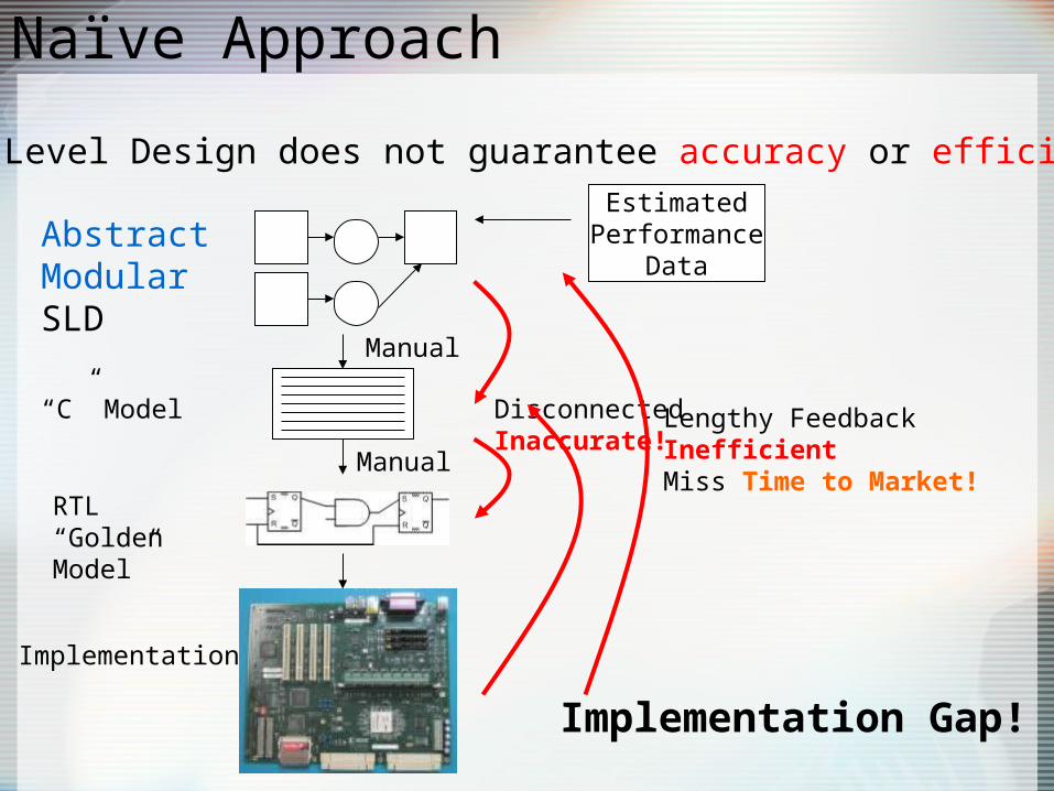
Naïve Approach
System Level Design does not guarantee accuracy or efficiency!!
AbstractModularSLD
Implementation
RTL “Golden Model”
“C” Model
Manual
Manual
DisconnectedInaccurate!
Lengthy FeedbackInefficientMiss Time to Market!
EstimatedPerformance
Data
Implementation Gap!

Improved Approach
AbstractModularSLD
EstimatedPerformance
Data
Technique 1: Modeling style and characterization for programmable platforms Real
Performance Data
Actual ProgrammablePlatform Description
Narrow the Gap
New approach has improved accuracy and efficiency by relating programmable devices and their tool flow with SLD (Metropolis). Retains modularity and abstraction.
From characterization flow
Functional level blocks of programmable components

Programmable FocusClassification Description
Granularity Abstraction level
CLB, Functional Unit, ISA
Host Coupling Coupling to host processor.
I/O, direct communication, same chip
Reconfiguration Methodology
How device is programmed.
Static, dynamic, partial
Memory Organization
How computations access memory.
Large block, distributed
Design Levels
Design Elements
Comm. Storage
Processing
Imple. SwitchesMUXES
RAMOrg.
CLB/ IPBlock
uArch CrossbarBus
Reg.FileSize
ExecutionUnit Type
ISA AddressSize
RegisterSet
CustomInstructions
Sys.Arch
Intercon.Network
BufferSize
Number/Types of tasks
K. Bondalapati, V. Prasanna, Reconfigurable Computing Systems, USC
P. Schaumont, et al, A Quick Safari Through the Reconfigurable Jungle, DAC, June 2001.

Copyright A. Sangiovanni-Vincentelli
Programmable Arch. Modeling
• Computation Services
• Communication Services
• Other Services
PPC405 MicroBlaze SynthSlaveSynthMaster
ProcessorLocalBus
(PLB)
On-ChipPeripheral
Bus(OPB)
OPB/PLB BridgeMapping Process
Computation ServicesRead (addr, offset, cnt, size), Write(addr, offset, cnt, size), Execute (operation, complexity)
BRAM
Task Before MappingRead (addr, offset, cnt, size)Task After MappingRead (0x34, 8, 10, 4)
Communication Services addrTransfer(target, master) addrReq(base, offset, transType, device) addrAck(device)
dataTransfer(device, readSeq, writeSeq)dataAck(device)

Copyright A. Sangiovanni-Vincentelli
Programmable Arch. Modeling
• Coordination Services
PPC Sched OPB SchedPLB SchedMicroBlaze
Sched
BRAM Sched General Sched
Request (event e)
-Adds event to pending queue of requested events
Resolve()
-Uses algorithm to select an event from the pending queue
PostCond()
-Augment event with information(annotation). This is typically the interaction with the quantity manager
GTime

Scheduled NetlistScheduling Netlist
Programmable Arch. Modeling
Modular Modeling Style Accurate & Efficient
• Compose scheduling and scheduled netlists in top level netlist.
• Extract structure for programmable platform tool flow.
Mapping Process
MicroBlaze
OPB OPB Sched
MicroBlaze Sched
Top Level Netlist
public netlist XilinxCCArch {
XilinxCCArchSched schedNetlist; XilinxCCArchScheduling schedulingNetlist; SchedToQuantity[] _stateMedia;}
StructureExtractor
File for Programmable Platform Tool Flow
• Type• Parameters• Etc
Connections
Topology

Copyright A. Sangiovanni-Vincentelli
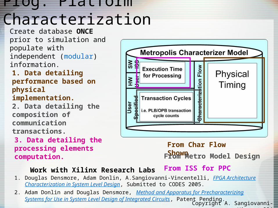
Prog. Platform Characterization
1. Create template system description.
2. Generate many permutations of the architecture using this template and run them through programmable platform tool flow.
3. Extract the desired performance information from the tool reports for database population.
Need to tie the model to actual implementation data!
Copyright A. Sangiovanni-Vincentelli
Prog. Platform Characterization
From Char Flow ShownFrom Metro Model Design
From ISS for PPC1. Douglas Densmore, Adam Donlin, A.Sangiovanni-Vincentelli, FPGA Architecture
Characterization in System Level Design, Submitted to CODES 2005.
2. Adam Donlin and Douglas Densmore, Method and Apparatus for Precharacterizing Systems for Use in System Level Design of Integrated Circuits, Patent Pending.
Create database ONCE prior to simulation and populate with independent (modular) information.
1. Data detailing performance based on physical implementation.2. Data detailing the composition of communication transactions.3. Data detailing the processing elements computation.
Work with Xilinx Research Labs

Architecture Extensions for Mapping• Programmable platforms allow for both SW and
HW implementations of a function.• Need to express which architecture
components can provide which services and with what affinity.
Mapping Process Mapping
Process
Dedicated HW DCT General PurposeuProc
Task Affinity
Execute
0
DCT 100
FFT 0
Task Affinity
Execute
50
DCT 20
FFT 2
Potential Mapping StrategiesGreedyBest Average Task Specific

Architecture Extensions for Preemption• Some Services are naturally preempted
– CPU context switch, Bus transactions• Notion of Atomic Transactions
– Prior to dispatching events to a quantity manager via the request() method, decompose events in the scheduled netlist into non-preemptable chunks.
– Maintain status with an FSM object (counter) and controller.
Decoder
Event Size 31
11
S1
S2
S3
Initial State

Copyright A. Sangiovanni-Vincentelli
Modeling & Char. Review
DedHW Sched
PLB Sched
BRAM Sched
GlobalTime
PPC Sched
Task1 Task2
PPC
Task3 Task4
DEDICATED HW
BRAM
PLB
Scheduled Netlist Characterizer
Scheduling Netlist
Media (scheduled) Process
Quantity ManagerQuantity
Enabled Event
Disabled Event

Copyright A. Sangiovanni-Vincentelli
Arch. Refinement Verification
• Architectures often involve hierarchy and multiple abstraction levels.
• These techniques are limited if it is not possible to check if elements in hierarchy or less abstract components are implementations of their counterparts.
• Asks “Can I substitute M1 for M2?”1. Representing the internal structure of a component.2. Recasting an architectural description in a new style.3. Applying tools developed for one style to another style.
Refinement Technique
Description Metropolis
Style/Pattern Based Define template components. Prove they have a desired relationship once. Build arch. from them.
Potential; TTL YAPI
Event Based Properties (behaviors) expressed as event lists. Explicitly look for this event patterns.
Discussed
Interface Based Create structure capturing all behavior of a components interface. Compare two models.
Discussed
D. Garlan, Style-Based Refinement for Software Architectures, SIGSOFT 96, San Francisco, CA, pg. 72-75.

Metropolis Refinement
• Internal Refinement– Depth Refinement1
• Interface Based• Focus on introducing new behaviors (Reason 1)
• Structural Refinement– Vertical Refinement1
– Horizontal Refinement1
• Event Based– Refinement Properties
• Focus on abstraction & synthesis (Reasons 2 & 3)1. Douglas Densmore, Metropolis Architecture Refinement Styles and Methodology,
University of California, Berkeley, UCB/ERL M04/36, 14 September 2004.

Depth Refinement
1. Douglas Densmore, Sanjay Rekhi, A. Sangiovanni-Vincentelli, MicroArchitecture Development via Successive Platform Refinement, Design Automation and Test Europe (DATE), Paris France, 2004.
Work with Cypress Semiconductor
Trace FIFO Scheduler Process Traces (*function calls abbr)
T1 Terminated()
T2 Terminated()
wRnd()*
T3 Terminated()
wRnd()* wRnd()*
T4 Terminated()
wRnd()* Tnated()*
qData ()*
T4 Cont putPolicy() PR1S()*
Bref = {T1, T3, T4} Bab = {T1, T2, T3, T4} Refinement!
This Observable Behavior can be captured for Metropolis processes in the model via the creation of a control flow graph (CFG)1.
1
3
2
4
5
6 7
89
10 11
12
terminated()
True False
whatRound()
Type & !Done Else
whatRound()checked_allterminated()
True False
FIFO SchedulerRef
queryData()
putPolicy()putRound1_
Status
FIFO SchedulerAb
1
3
2
4
5
6 7
89
10 11
12
terminated()
True False
whatRound()
Type & !Done Else
whatRound()checked_allterminated()
True False
queryData()
putPolicy()putRound1_
Status
!Type & !Done
Trace containment check for single threaded processes

Vertical Refinement
BRAM Sched
Cache Sched
Scheduled Netlist
Scheduling Netlist
Mapping Process
Mapping Process
Rtos Sched
Neworigins andamountsof eventsscheduledand annotated
Sequential
Concurrent
BRAM
PPC405
PLBCache
Rtos
PLB Sched
PPC Sched
Original Sequential Concurrent 1 Concurrent 2
E1 (CPURead) E1 (RTOSRead) E1 (CPURead) E1 (CPURead)
E2 (BusRead) E2 (CPURead) E2 (CacheRead) E2 (CacheRead)
E3 (MemRead) E3 (BusRead) E3 (BusRead)
E4 (MemRead) E4 (MemRead)
•Definition: A manipulation to the scheduled netlist structure to introduce/remove the number or origin of events as seen by the scheduling netlist.

Horizontal Refinement
BRAM Sched
Cache Sched
Scheduled Netlist
Scheduling Netlist
Mapping Process
Mapping Process Rtos Sched
Orderingof eventrequestschanged
BRAM
PPC405
PLBCache
Rtos
PLB Sched
PPC SchedArb
ControlThread
Original* Refined (interleaved)E1 (BusRead) -> From CPU1 E1 (BusRead) -> From CPU1
E2 (BusRead) -> From CPU1 E3 (BusRead) -> From CPU2
E3 (BusRead) -> From CPU2 E2 (BusRead) -> From CPU1
E4 (BusRead) -> From CPU2 E4 (BusRead) -> From CPU2
PPC405 PPC Sched •Definition: A manipulation of both the scheduled and scheduling netlist which changes the possible ordering of events as seen by the scheduling netlist.
*Contains all possible orderings if abstract enough

Refinement Properties
• Properties expressed as event sequences as seen by the scheduling netlist.
Bad Resolve() Good Resolve()
CPU E1, E2, E3, E4 E4, E1, E2, E3
Bus X, X, X, X, E4 X, E4
Mem X, X, X, X, X, E4 X, X, E4
Bad Resolve() Good Resolve()
CPU (0) E1, E2 E1 E1, E2 E1
CPU (1) E2, E3 E2 E2, E3 E2
Bus (1) E1, EX EX E1, EX EX
CPU (2) E3 E3 E3 E3
Bus (2) E1, E2 E2 E1, E2 E1
CPU(3)
Bus (3) E1, E3 E3 E2, E3 E2
E1 (CPUExe)E2 (CPUExe)E3 (CPUExe)
E4(CPURead)
Resource Utilization
Latency

Copyright A. Sangiovanni-Vincentelli
File for Xilinx EDK Tool Flow
IP Library
1. Select an application and understand its behavior.
2. Create a Metropolis functional model which models this behavior.
3. Assemble an architecture from library services or create your own services.4. Map the functionality to the architecture.
5. Extract a structural file from the top level netlist of the architecture created.
On-ChipPeripheral
Bus(OPB)
SynthMaster
SynthSlave
MicroBlaze
Mapping ProcessMapping
Process
Mapping ProcessMapping
Process
BRAMBRAM
Preprocessing DCT Quantization Huffman
JPEG Encoder Function Model (Block Level)
StructureExtractor
Top Level Netlist
Example Design

Copyright A. Sangiovanni-Vincentelli
Example Design Cont. Problem StatementApproachContribution
File for Xilinx EDK Tool Flow
Permutation Generator
ISS Info CharDataTransaction
Info
Platform Characterization Tool (Xilinx EDK/ISE Tools)
Characterizer Database
Software Routinesint DCT (data){Begin calculate ……} Automatic32 Bit Read = Ack, Addr, Data, Trans, Ack
Manual
Hardware RoutinesDCT1 = 10 CyclesDCT2 =5 CyclesFFT = 5 Cycles
Manual
1. Feed the captured structural file to the permutation generator.
2. Feed the permutations to the Xilinx tools and extract the data.
3. Capture execution info for software and hardware services.
4. Provide transaction info for communication services.
Permutation 1 Permutation 2 Permutation N

Copyright A. Sangiovanni-Vincentelli
Example Design Cont.
Preprocessing DCT Quantization Huffman
JPEG Encoder Function Model (Block Level)
On-ChipPeripheral
Bus(OPB)
SynthMaster
SynthSlave
MicroBlaze
Mapping ProcessMapping Process
Mapping ProcessMapping
Process
BRAMBRAM
ISS InfoCharDataTransaction
Info
2. Refine design to meet performance requirements.
3. Use Refinement Verification to check validity of design changes.
• Depth, Vertical, or Horizontal• Refinement properties
1. Simulate the design and observe the performance.
Execution time 100msBus Cycles 4000Ave Memory Occupancy 500KB
BRAM
ConcurrentVertical Refinement
New Algorithm
Depth
VerificationTool
Yes? No?
Execution time 200msBus Cycles 1000Ave Memory Occupancy 100KB
4. Re-simulate to see if your goals are met.
Backend Tool Process:1. Abstract Syntax Tree (AST) retrieves structure.
2. Control Data Flow Graph - DepthFORTE – Intel ToolReactive Models – UC Berkeley
3. Event Traces – Refinement Properties.
Vertical RefinementHorizontal Refinement

40
Goals for Metro II
• Import heterogeneous IP– Different languages– Different models of computation
• Key Platform-based Design Activities– Behavior-Performance Separation
• Quickly change performance characteristics of models
– Design Space Exploration• Relate functionality and architecture • Verify relationships between different
abstraction levels
CoordinationFramework
Event-orientedFramework
3-Phase Execution

Component
IP
Wrapper
Components, Ports, and Connections
required port
providedport
view port• Ports
– Coordination: provided, required– View ports
• Connections– Each method in interface for provided-required
connection associated with begin and end events
• IP is wrapped to expose framework-compatible interface
• Components encapsulate wrapped IP

Mappers
• Mappers are objects that help specify the mapping– Bridge syntactic gaps only– E.g. Missing method parameters
Mapper
Func. Comp
Arch. Comp
• Mapping occurs at the component level– Between components
with compatible interfaces
– Possibly many functional components mapped to a single architectural component

Adaptor• Bridge different models of computation
(MoCs)
Component1
(MOC1)
Component1
(MOC1)
Component2
(MOC2)
Component2
(MOC2)Adaptor
Events
?How to communicate with different MoC?
Events
• Adaptor transforms the tags of the events to make different MoCs compatible• Values are not changed• Will not produce/discard events
43

Implementation of Adaptor
• Adaptor contains internal channels for storing the information of events, and a process to transforms the tags of events
• Adaptor will be executed during the base model execution phase (phase 1)
• Test case with an adaptor between dataflow and FSM semantics
• Will be further tested in the cruise control and heating and cooling project
44

45
Metro II System Architecture Status
sc_event
m2_method
m2_port
m2_event
sc_module
m2_interface
Mapper Adaptor
m2_component Annotator
Constraints
Scheduler
m2_manager
Implementation Platform: SystemC 2.2
Metro II Core
Implementation started

Phase 1 Phase 2
Behavior-Performance Separation in Metropolis
• Processes make explicit requests for annotation• Annotation/scheduling are intertwined
– Iteration between multiple quantity managers• Challenges in GM case study
– Vehicle stability application on distributed CAN architecture
– Interactions between global time QM and resource QM difficult to debug
P1P2
R
Global Time
Resource
Scheduler
2. Quantity
Resolution
1. Explicit quantity requests
3. Granting of requests

Execution Semantics in Metro II
• Metro II components (imperative code) are run by processes (sequential thread of execution).
Not Blocked
Blocked
start Propose Event or Wait
Event Enabled or Notified
Metro II Process States
47

48
Execution Semantics in Metro II
Phase 1
P1P2
R
Phase 2
Physical Time
1. Block processes at interfaces
2. AnnotationsPhase 3
Logical Time
Resource Scheduler
3. Sched.
Resolution
4. Enable some processes
ProposedEvent proposed by Process
Event Annotated
Event Disabled by CS must be reannotated
Event enabled by CS then processcontinues execution
Annotated
Event Disabled by CS, but keep the same annotations
Inactive
start

Phases and Events
• Each phase is allowed to interact with events in a limited way– Keep responsibilities separate
Phase Events Tags Values
Propose
Disable
Read Write
Read Write
Base Yes Yes Yes
Annotation
Yes Yes Yes
Scheduling
Yes Yes Yes

Assumptions• “Blocking”
– Both the architectural and functional models should be allowed to block
• Scheduling– Functional model execution is valid (i.e.
doesn’t deadlock)
• Mapping– The enabling of events in one model,
correspond directly to the enabling of other events
50

Mapping• Mapping in Metro II requires:
– Assigning functional operations to architecture services. Many-to-one relationship.
• This is done through events.
• Issues to resolve:– Which types and in what order should events
be related between function and architecture?
– How processes present in the functional model trigger architectural components? How does simulation execution originate?
51

52
Proposal 1
F G
A B
Function
Architecture
FR.b FR.e
GP.b G.body GP.e
AP.b A.body AP.e
Functional model initiates execution and is followed by the architecture model.•Port Mapping Conventions
• Required to Provided
• Call graph Example
PR
P
Synchronized Events - - -Direct Event Ordering __ Key

Proposal 2
Architectural model initiates execution and is followed by the functional model.•Port Mapping Conventions
• Required to Provided
• Call graph Example
F G
A B
Function
Architecture
PR
P
53
Synchronized Events - - -Direct Event Ordering __ Key
FR.b FR.e
AP.b A.body AP.e
GP.b G.body GP.e

Proposal 3
54
Functional and architectural model execute concurrently.
•Port Mapping Conventions• Provided to Provided
F G
A B
Function
Architecture
PR
P
• Call graph Example
Synchronized Events - - -Direct Event Ordering __ Key
FR.bFR.e
AP.b A.body AP.e
GP.b G.body GP.e

Key Points of Proposals
• Proposal 1 – Functional model execution cannot be determined by architectural state.
• Proposal 2 – Architecture model must block if the functionality blocks.
• Proposal 3 – Requires that the component’s execution be granular enough to support explicit synchronization opportunities (i.e. protocols).
55

Mapping Granularity Tradeoff
• Granularity changes may be needed to support proposal 3.
• The functional and architectural models need not have the same level of granularity.
56
1. Grab bus access2. Read fifo status3. If it can proceed to read/write
Read/Write; release bus4. Else
Release bus; wait a random number of cycles; goto 1
FIFO READ Begin
FIFO READ END

Example Design Scenario
57
Shared FIFO is another design scenario
MJPEG
Architecture Model
Ex
Ex
WW W
Ex Ex Ex
R R RSource FIFO1 DCT
Arch1
Bus
Functional Model
FIFO2 FIFO3Quant Huffman
ExS ExD ExQ ExH
Ex
Arch2
Ex
Arch3
Ex
Arch4
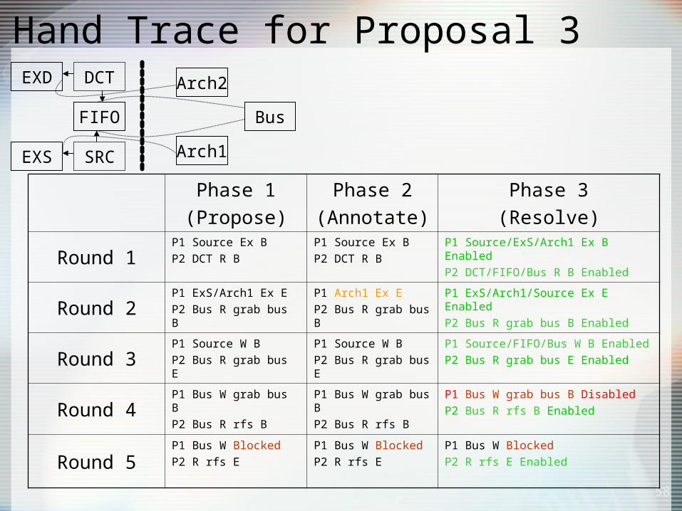
Hand Trace for Proposal 3
58
Phase 1(Propose)
Phase 2(Annotate)
Phase 3(Resolve)
Round 1P1 Source Ex BP2 DCT R B
P1 Source Ex BP2 DCT R B
P1 Source/ExS/Arch1 Ex B EnabledP2 DCT/FIFO/Bus R B Enabled
Round 2P1 ExS/Arch1 Ex EP2 Bus R grab bus B
P1 Arch1 Ex EP2 Bus R grab bus B
P1 ExS/Arch1/Source Ex E EnabledP2 Bus R grab bus B Enabled
Round 3P1 Source W BP2 Bus R grab bus E
P1 Source W BP2 Bus R grab bus E
P1 Source/FIFO/Bus W B EnabledP2 Bus R grab bus E Enabled
Round 4P1 Bus W grab bus BP2 Bus R rfs B
P1 Bus W grab bus BP2 Bus R rfs B
P1 Bus W grab bus B DisabledP2 Bus R rfs B Enabled
Round 5P1 Bus W BlockedP2 R rfs E
P1 Bus W BlockedP2 R rfs E
P1 Bus W BlockedP2 R rfs E Enabled
EXS
FIFO
DCT
SRC Arch1
Arch2
Bus
EXD

PRET Functional Model
TLP1 TLP2 TLP3
TLE1 TLE2 TLE3
1 2 3Period 5, 3, 11Start 8, 3, 10Exe Time 1, 2, 3
3
10
1 4
8
2
3 3 8
8 1
11 2
4
3 5 6 8 9 10 13 14 18 21 24 32
59
Dummy Events Added
PREcision Timed machine work at UC Berkeley is going to require support for a variety of timing models.
Expose Execution Events

Metro II Mapping Conclusions• Metro II mapping uses events to
synchronize execution between the functional and architectural model.
• Potential tradeoffs in granularity and expressiveness depend on the mapping style (Metro II supports various).
• Established a style to describe Metro II execution and started a set of design scenarios to discuss the tradeoffs.
60

Design Activity: UMTS Case Study• UMTS is a mobile communication protocol
standard– Universal Mobile Telecommunications System– 3G cell phone technology– Often used in Software Defined Radio (SDR)
• Started with C and SystemC models as baseline– Source of Metro II functional models– Profiling to use in architecture models– Comparisons for Metro II simulation results
• Have both DLL and PHY level SystemC models– Converted only data link layer to Metro II
61

UMTS DLL Function Model
Tr Buffer Segment.RLC Header
AddCiphering
TrCH Type Switch
C_T_MuxTr_format
sel
PHY
CTDEMUX
Rx_TrCH Type Switch
DecipheringRLC Header
RemReassembly
Transmitter
Receiver
fifo
RLC
MAC
MAC RLC
13 Computational Components12 FIFOs
62

Metro II UMTS Models
Focused on the DLLlayer
Initial SystemCmodel was convertedto Metro II
Two Models:• Pure functional model with blocking read and write semantics.
• Timed model with a scheduler and preemption.
63

Synchronization Mechanisms
UMTS example exposed two approaches to synchronization in Metro II:
Explicit Synchronization:Use the underlying simulation framework directlyi.e. SystemC “or/and” waits
Constraints:Move synchronization from phase 1 to phase 3 completely.
64

Metro II: Service Modeling
65
• Two basic architecture modeling styles: cycle accurate runtime analysis vs. off line, pre-profiled approach
ArchitectureComponent
IMEM
MapperTask
Cycle AccuratePipeline

SPARC Runtime Processing Element
A runtime processing based element was created to model the Leon 3 SPARC processor
66

Architecture Model Overview
Tasks for mapping 1-to1 with functional components
RTOS for scheduling events from N tasks to M processing elements
Three scheduling policies:• Round Robin• Fixed Priority• FCFS
Numerous configurations of processing elements (48 chosen)
67

68
Metro II Complete System
OS
Sparc1 ARM7 uB
T1 T2 TN
FC1 FCN
M1 M2 MN
Logical Time Scheduler
Annotator
Phase 1Phase 1
Phase 2Phase 2
Phase 3Phase 3
Mapping Constraint Solver

UMTS Case Study Outcomes
• Processing elements include– ARM7, ARM9: GPP profiling approach– Microblaze: Programmable platform flow– SPARC: runtime profiling with C code
snippets of core routines• 48 different mappings explored
– 11 PEs, 1 PE, combinations of 4 PEs broken down by RLC tx/rx and MAC tx/rx
– 9 classes within the 48 mappings
69

48 Mappings
70

Estimated Execution Time and Utilization
11uB; +3.1%11uB; +3.1%1uB; +2%1uB; +2%
4uB; +16%4uB; +16%
71
Measured exe. time:Measured exe. time:

Execution Time and Utilization Analysis
• Round Robin– Mapping #1 (fastest, 11 SPARCs) and #46
(slowest, 1 uBlaze) had a 2,167% difference
• Priority– Avg. execution time reduced by 13% over
round robin– Avg. utilization decreases by 2%
• FCFS– Avg. execution time reduced by 7%– Avg. utilization increases by 27%
72

Runtime analysis across phases and mapping classes
An average 61% of the time is spent in Phase 1, 5% in Phase 2 and 17%in Phase 3 (third section). For most models using RTP the averages are 93%, 0.9%, and 3% respectively.
For pure profiled (PP) mappings they are 21%, 7% and 26%.
For mixed classes thenumbers are 82%, 2.6% and 7.6%.
Key message: runtime processing elements dominate.
Despite all of this, the average runtime to process 7000 bytes of data was 54 seconds.
73

SystemC vs. Metro II
• Metro II timed functional model has a 7.4% increase in runtime over SystemC timed functional model
• Mapped Metro II model is 54.8% faster than timed SystemC model– Metro II phases 2 and 3 have significantly less
overhead than the timer-and-scheduler based system required by the SystemC timed functional model
• In a comparison of the Metro II timed model running without constraints and one running with them, the average runtime decrease was 25%
74

Design Effort
• Entire design– 85 files– 8,300 LOC
• Mapping change affects only 2 files• Metro II conversion affects 1% of lines
in each file– 58% of these lines relate to constraint
registration
• SystemC SPARC model conversion adds only 3.4% to code size (92 lines)
75

Future Directions
• Complete another design using similar architecture as in UMTS but with an emphasis on the communication structure– H.264 decoding
• Produce documentation of design activities– Recently put tech report on “Metro II
Semantics for Mapping” on GSRC website– Metro II journal paper in progress
76

Design Activity: Heating and Cooling in Building Automation
77
Room 1 (P,T) Room 2 (P,T)
Environment (P,T)
P,T P,T
Sink
Source (Temp and Pressure constant)
Door (Crack Model)

DOP Center Modeling
Sensor to controller-Latency: 0.3 s-Message length: 8 bits-Period :1 s
Sensor to controller-Latency: 0.3 s-Message length: 8 bits-Period :1 s
Controller to actuators-Latency: 0.4 s-Message length:16 bits-Period:1 s
Controller to actuators-Latency: 0.4 s-Message length:16 bits-Period:1 s
Network library-Field bus 78kb/s (ARCNET)-Field bus 2.5Mb/s (ARCNET)-Constraints: topology, degree, length-Two level hierarchical network
Network library-Field bus 78kb/s (ARCNET)-Field bus 2.5Mb/s (ARCNET)-Constraints: topology, degree, length-Two level hierarchical network
8 Networks (2.5Mb/s) plus a high speed, second level network-Estimated cost $21385 -Bus load: 96kb/s(min), 237kb/s(max),139kb/s(avg), Networks are distance and degree limited, not bandwidth limited
8 Networks (2.5Mb/s) plus a high speed, second level network-Estimated cost $21385 -Bus load: 96kb/s(min), 237kb/s(max),139kb/s(avg), Networks are distance and degree limited, not bandwidth limited

COSI and Metro II: Design Flow
79
Metro II Functional
Model
MetroIIArchitecture
Model
MappingStep 1
COSIStep 2
Step 3
Metro IISimulation Results
COSISynthesisresults
Refined Metro IIArchitecture
Model

GSRC Quarterly Workshop
80
Room Temperature
s
Room Temperature
s
Controller1Controller1
A2A2
A1A1
S2S2
S1S1
ModelicaModel
CORBA communication
FIFO_a1cFIFO_a1c
FIFO_a2cFIFO_a2c
FIFO_s1cFIFO_s1c
FIFO_s2cFIFO_s2c
MetroII
OpenModelica
Heating and Cooling Functional Model
Controller2Controller2

Current Status
• Completed and tested function model – Interacts with Modelica model– Room number is configurable (both full
and mini-DOP center models created).
• Created architecture model with mapping– Processor, sensor, actuator numbers are
configurable– Support multiple controller tasks on same
processor (with orthogonalized scheduling policy model)
81