metro rail design criteria section 3...
TRANSCRIPT
METRO RAIL DESIGN CRITERIA
SECTION 3
CIVIL
METRO RAIL DESIGN CRITERIA SECTION 3 / CIVIL
DE304.03 Revision 1 : 11-09-10 Metro Baseline 3-i Re-baseline: 01-19-10
TABLE OF CONTENTS PAGE
3.1 SCOPE .............................................................................................................................. 4
3.2 BASIS FOR CRITERIA ..................................................................................................... 4
3.3 UTILITIES ......................................................................................................................... 4
3.3.1 General ............................................................................................................ 4 3.3.2 Sanitary Sewers and Storm Drains ................................................................. 6 3.3.3 Water ............................................................................................................... 8 3.3.4 Gas .................................................................................................................. 9 3.3.5 Electric Power .................................................................................................. 9 3.3.6 Telephone ...................................................................................................... 10 3.3.7 Telegraph Telecommunications .................................................................... 10 3.3.8 Other Communication Cable Systems .......................................................... 11 3.3.9 Fire and Police Alarm Systems ..................................................................... 11 3.3.10 Park Facilities ................................................................................................ 11 3.3.11 Street Lights .................................................................................................. 11 3.3.12 Traffic Signals ................................................................................................ 12 3.3.13 Oil Pipe Lines, and Steam Lines ................................................................... 12 3.3.14 Abandoned Utilities ........................................................................................ 12
3.4 RIGHT-OF-WAY ............................................................................................................. 13
3.4.1 General .......................................................................................................... 13 3.4.2 Types of Right-of-Way ................................................................................... 13 3.4.3 Right-of-Way Criteria and Limits .................................................................... 14 3.4.4 Right-of-Way Information Requirements ....................................................... 18 3.4.5 Surveys and Monumentation ......................................................................... 19
3.5 CONTROL OF ACCESS ................................................................................................. 20
3.5.1 General .......................................................................................................... 20 3.5.2 Crossings - Deleted ....................................................................................... 20 3.5.3 Right-of-Way Barriers .................................................................................... 20
3.6 SERVICE ROADS ........................................................................................................... 21
3.7 STREETS ........................................................................................................................ 21
3.7.1 General .......................................................................................................... 21 3.7.2 Maintenance of Traffic ................................................................................... 23 3.7.3 Roadway Geometrics .................................................................................... 23 3.7.4 Paving ............................................................................................................ 26 3.7.5 Concrete Bus Pads ........................................................................................ 26 3.7.6 Bus Turnouts ................................................................................................. 26 3.7.7 Traffic Control Devices .................................................................................. 26 3.7.8 Street Signing and Striping ............................................................................ 29 3.7.9 Parking Meters .............................................................................................. 29 3.7.10 Ramps and Curb Cuts ................................................................................... 29 3.7.11 Sidewalks ...................................................................................................... 29
METRO RAIL DESIGN CRITERIA SECTION 3 / CIVIL
DE304.03 Revision 1 : 11-09-10 Metro Baseline 3-ii Re-baseline: 01-19-10
3.7.12 Ventilation Grating Opening .......................................................................... 30 3.7.13 Vaults ............................................................................................................. 30 3.7.14 Driveways ...................................................................................................... 30 3.7.15 Landscape Areas and Street Trees ............................................................... 30 3.7.16 Exit Hatches .................................................................................................. 31
3.8 DRAINAGE ..................................................................................................................... 31
3.8.1 General .......................................................................................................... 31 3.8.2 Hydrology ...................................................................................................... 31 3.8.3 Design Storm Drainage Area ......................................................................... 32 3.8.4 Rainfall Intensity ............................................................................................ 32 3.8.5 Surface Drainage ........................................................................................... 32 3.8.6 Drainage Structures ....................................................................................... 33 3.8.7 Storm Drains .................................................................................................. 34 3.8.8 Flood Control ................................................................................................. 35
3.9 SITE WORK AND PARKING FACILITIES ..................................................................... 35
3.9.1 General .......................................................................................................... 35 3.9.2 Traffic Modes ................................................................................................. 36 3.9.3 Metro System Streets Design Elements ........................................................ 36 3.9.4 Site Work Criteria .......................................................................................... 38 3.9.5 Traffic Control Devices .................................................................................. 41 3.9.6 Parking General (See Figures 3.8 through 3.21) ........................................... 42 3.9.7 Kiss-and-Ride Facilities ................................................................................. 44
3.10 CORROSION CONTROL ............................................................................................... 44
3.10.1 Introduction .................................................................................................... 44 3.10.2 General .......................................................................................................... 46 3.10.3 Soil Corrosion Control ................................................................................... 47 3.10.4 Stray Current Corrosion Control .................................................................... 61 3.10.5 Atmospheric Corrosion Control ..................................................................... 80
METRO RAIL DESIGN CRITERIA SECTION 3 / CIVIL
DE304.03 Revision 1 : 11-09-10 Metro Baseline 3-iii Re-baseline: 01-19-10
TABLES Table Number Title
3.1 Design Criteria for Mainline Track-to-Earth Resistance Levels
FIGURES Figure Number Title
3.1 Right-of-Way Typical Section Retained At-Grade Section through Private Property
3.2 Right-of-Way Typical Section Aerial Section through Private Property 3.3 Metro Right-of-Way Monument 3.4 Control of Access at-Grade Condition 3.5 Control of Access Public Area Retained 3.6 Control of Access Transit R.O.W. Retained 3.7 Design Vehicles and Minimum Turning Paths
3.7.1 5 mph Bus Turning Template 3.7.2 7 mph Bus Turning Template 3.7.3 10 mph Bus Turning Template 3.7.4 15 mph Bus Turning Template 3.8 Normal Car Parking Lot Layout - 45 9’-0” Stalls 3.9 Normal Car Parking Lot Layout - 60 9’-0” Stalls
3.10 Normal Car Parking Lot Layout - 90 9’-0” Stalls 3.11 Small Car Parking Lot Layout - 45 8’-0” Stalls 3.12 Small Car Parking Lot Layout - 60 8’-0” Stalls 3.13 Small Car Parking Lot Layout - 90 9’-0” Stalls 3.14 NOT USED 3.15 Parking Lot Stall Lines - 45 3.16 Parking Lot Stall Lines - 60 3.17 Parking Lot Stall Lines - 90 3.18 Sawtooth Bus Bays 3.19 Parallel Bus Bays 3.20 Parking Structure Entrances and Exits Sight Distance Requirements 3.21 Driveways for Parking Structures
METRO RAIL DESIGN CRITERIA SECTION 3 / CIVIL
DE304.03 Revision 1 : 11-09-10 Metro Baseline 3-4 Re-baseline: 01-19-10
CIVIL
3.1 SCOPE
This section establishes the basic Civil Engineering Criteria to be used in the design of Los Angeles County Metropolitan Transportation Authority (Metro) Rail Transit Projects and the related work that includes criteria for the design of transit system alignments, trackway subgrade, drainage, determination of rights-of-way, control of access, service roads, and relocation of utility systems.
Note: Any deviation from the following specific requirements is subject to prior Metro approval.
3.2 BASIS FOR CRITERIA
The basic requirement of any transit geometric design is to provide comfortable, economical, and efficient transportation for passengers while maintaining adequate factors of safety with respect to overall operation, maintenance, and vehicle stability.
The criteria presented herein relating to the design of operational components emphasize safety and passenger comfort and follow accepted engineering practices used in current operating rapid transit and railroad systems.
The criteria relating to other elements of design and to work items necessitated by transit system construction, such as miscellaneous utility work, are based on the current specifications and practices of the agencies concerned in the jurisdiction involved.
HRT refers to Heavy Rail Transit Systems and LRT refers to Light Rail Transit System.
3.3 UTILITIES
3.3.1 General
A. These criteria govern the maintenance, support, restoration, and construction of utilities encountered by, or affected by, the construction. In the performance of work, due consideration shall be given to the needs of the transit system, the requirements and obligations of the utility organizations, traffic requirements, and the cooperative agreements between the Agencies or Companies and Metro.
1. Utilities comprise facilities belonging to governmental agencies other than Metro, Public Utility Corporations, and private parties, and include service lines to adjoining properties.
2. Utilities encountered or close enough to be affected by transit construction may be:
a. Supported and maintained complete in place during construction and continued in service following completion of the transit facilities.
b. Temporarily relocated and maintained; then, upon completion of transit facilities, replaced by new utilities.
METRO RAIL DESIGN CRITERIA SECTION 3 / CIVIL
DE304.03 Revision 1 : 11-09-10 Metro Baseline 3-5 Re-baseline: 01-19-10
c. Permanently relocated beyond the immediate limits of transit construction.
B. Utility service to abutting properties shall not be interrupted and, if temporarily relocated, shall be permanently restored to its prior location upon completion of work.
C. Replacements for any existing utilities, including government facilities, and pavements shall be designed to provide service or capacity equal to that offered by the existing installations. Designer shall comply with local codes and standards of the agencies having jurisdiction.
Unless specifically noted otherwise herein, the latest edition of the code, regulation, standard and standard plan that is applicable at the time the design is initiated shall be used. If a new edition or amendment to a code, regulation, standard or standard plan is issued before the design is completed, the Designer shall determine the impact of the change and seek Metro direction on how to proceed.
Designer shall request Metro direction on current minimum standards to be used for design of replacement facilities.
D. Improvements to utilities shall not be included unless specifically directed by Metro.
E. All designs involving maintenance, support, and relocation or other utility work shall conform to the applicable specifications, criteria, and standard drawings of the concerned corporations or agencies.
F. Record elevations of all utilities shall be adjusted to project datum. Pertinent utility elevations and locations shall be checked by field survey, and, where critical to design, by digging test holes at locations approved by Metro. Designer shall request Metro direction on current minimum standards to be used for design of replacement facilities, and have direction and concurrence of the utility or agency affected.
G. The Designer shall consider plans developed, or being developed, by others in adjoining sections to ensure that the overall utilities systems will be consistent with those existing before the start of construction, and that the systems will be compatible with those of the transit system.
H. Design of utility rearrangements shall ensure that construction of the transit facilities may proceed without undue hindrance and without endangering the continuity of utility service. The design shall consider space requirements for equipment and materials and clearances for installation of temporary traffic decking. The Designer shall request direction from Metro on allowable profiles and clearances for temporary deck structures. Design practice for a normal width underground station is to provide minimum clearance of 54 inches between top of temporary decking and the top of the relocated utility profile. These clearances may vary with the length of span required.
I. Take into account the needs of each utility for maintenance and accessibility when assigning vertical alignments.
METRO RAIL DESIGN CRITERIA SECTION 3 / CIVIL
DE304.03 Revision 1 : 11-09-10 Metro Baseline 3-6 Re-baseline: 01-19-10
J. Where utilities cross under or run parallel to rail alignments consider live loads imposed by transit facilities in design of utility and utility casings. Protection of both the utility and the transit facility must be considered.
K. Utilities which penetrate through or cross over transit structures shall be designed to prevent shear failure and shall be encased if necessary to prevent damage. All utilities encasement shall be designed o comply with local governing agencies’ standards and requirements.
3.3.2 Sanitary Sewers and Storm Drains
A. Codes and Standards
1. The Designer shall determine the ownership of all impacted Sewer and Drainage Facilities prior to initiating detailed design of facility rearrangements.
2. Design and construction of Sanitary Sewer laterals to abutting
properties shall conform to City and County of Los Angeles requirements or other applicable local codes. All sanitary sewer and storm drain discharges for both operation and construction of the Metro Rail Transit (MRT) shall be properly permitted and compliant with appropriate jurisdictional authority.
B. Sanitary Sewers
1. The Designer shall specify to the Contractor to provide closed circuit
television video (CCTV), both prior to and post-construction for all sanitary sewers, sanitary sewer maintenance holes and appurtenances that are affected by the project either crossing the right-of-way (rail tracks, wall, structure, etc.) or parallel to the right-of-way, that all sanitary sewer lines shall be videotaped prior to construction. If connecting to an existing manhole, videotape the manhole and the connection. If the rail tracks are on top of the sanitary sewer or storm drain, videotape the affected line from manhole to manhole.
2. Sanitary sewer mains and service laterals to adjoining properties shall
be maintained/protected by supporting in place, by providing alternative temporary facilities or by diverting to other points, as approved by the governing agency.
3. Temporary sanitary sewer piping systems shall be of adequate size
and slope to handle the flows of those sewers taken out of service. Minimum of a 3ft/sec self cleansing velocity shall be maintained. No sanitary sewage shall be discharged onto the project construction sites or at any other location.
4. Temporary sanitary sewer facilities provided by contractor during
construction shall be removed after project completion and after permanent facilities are in operation.
5. Capacity and service of replacement sanitary sewer system shall be
METRO RAIL DESIGN CRITERIA SECTION 3 / CIVIL
DE304.03 Revision 1 : 11-09-10 Metro Baseline 3-7 Re-baseline: 01-19-10
equivalent to existing system and shall meet or exceed current design standards, based on the published design requirements of the agency having jurisdiction.
6. Conduits shall be designed to maintain minimum velocities and flow
depths per controlling agency's standards. 7. Separation between sanitary sewers and water lines shall be per the
applicable jurisdictional agency’s design requirements. In general, maintain 10 feet minimum horizontal and 1 foot minimum vertical separation, or follow as required by the applicable jurisdictional agency’s design requirements. The most stringent requirements shall apply.
8. Review site specific condition, including flow capacity of existing
sanitary sewers affected by the MRT, and incorporate such modifications into the relocation or realignment plan to protect both utility and MRT facility.
C. Storm Drains
1. The Designer shall specify to the Contractor to provide closed circuit
television (CCTV) video, both prior to and post-construction for all storm drain, storm drain maintenance holes and appurtenances that are affected by the project either crossing the right-of-way (rail tracks, wall, structure, etc.) or parallel to the right-of-way. If the conveyance system is water tight, provide alternative temporary or permanent facilities or divert flows to other points.
2. All temporary storm drainage facilities used during construction shall
be removed and restored with new permanent facilities at project completion. Restored facilities shall have capacities equivalent to those of existing facilities and shall meet or exceed current design standards of the agency having jurisdiction. Hydrology and Hydraulic calculations shall be provided to Metro and local agency to verify that the added volume within the restored facility is within capacity.
3. Review FEMA maps as well as area drainage conditions for local
flooding and incorporate into design of storm drain facilities to provide for protection of transit facilities.
4. New pipe shall have rubber gasket joints where it crosses the transit
facilities. 5. No surface drains from adjoining areas shall be connected to the transit drainage system. 6. All storm drain discharge locations, catch basins and general storm water runoff management shall comply with the Standard Urban Stormwater Mitigation Plan (SUSMP) issued by the Los Angeles Regional Water Quality Control Board and other regulatory agencies.
METRO RAIL DESIGN CRITERIA SECTION 3 / CIVIL
DE304.03 Revision 1 : 11-09-10 Metro Baseline 3-8 Re-baseline: 01-19-10
7. New drainage facilities and connections to existing facilities shall be designed using the criteria in Section 3.8. 8. All corrugated metal pipes, PVC pipes and ductile iron pipes crossing Metro Rail Tracks or within the Metro Right-of-Way shall be replaced by RCP and shall be designed to support rail vehicle traffic loading. 9. All new pipes designed to cross under any CMU sound wall or retaining wall shall be encased in concrete for a distance of 5-feet from both sides of the wall. 10 All existing pipes that run under new walls shall be encased in concrete and designed to support loading from the wall.
3.3.3 Water
A. Codes and Standards
1. All maintenance, relocation, restoration, and construction of water mains and appurtenances shall conform to current design standards and criteria, specifications and practices of the agencies having jurisdiction. The Designer shall determine the ownership of all impacted water lines prior to initiating detailed design of facility rearrangements.
2. Construction of water services to abutting properties shall conform to applicable local codes.
B. General
1. Replacement of existing water mains and appurtenances shall provide capacities and services equivalent to those of existing facilities.
2. Services to adjoining properties shall be maintained by supporting in place, by providing alternative temporary facilities, or by diverting from other points.
3. Upon approval from owners water lines through cut-and-cover construction shall be supported in place and braced to resist internal and external forces. New lines shall be aligned such that further relocation for placement of temporary decking or station construction will not be required.
4. Where major water distribution facilities cross the project alignment install emergency isolation valves outside the construction site if suitable isolation valves do not presently exist. Location and type of valve shall comply with criteria and requirements of the agency having jurisdiction.
5. Cathodic Protection shall be provided for all ferrous metal pipelines in accordance with standards and criteria of the agency having jurisdiction.
6. New water lines shall be welded steel pipe or ductile iron pipe as required by the utility agency.
METRO RAIL DESIGN CRITERIA SECTION 3 / CIVIL
DE304.03 Revision 1 : 11-09-10 Metro Baseline 3-9 Re-baseline: 01-19-10
3.3.4 Gas
A. Codes and Standards
All work on, or adjacent to, gas lines shall conform to regulations and standards of The Gas Company.
B. General
1. After consultation with Metro, the Designer shall inform The Gas Company if and where the transit system will affect the company's plant.
2. Removal, installation, and connection of temporary or permanent gas mains shall be performed in accordance with the Gas Company Standards and Practices.
3. Where possible new gas lines shall be placed within the street parkway or in the curbside lane one foot from the lip of the gutter.
4. Maintain at least two feet of clearance from other utilities.
5. Major gas line distribution facilities crossing the project alignment will have emergency isolation valves installed in accordance with The Gas Company standards.
3.3.5 Electric Power
A. Codes and Standards
All maintenance, relocation, and restoration of electric lines throughout the transit system shall conform to the current practices of the electric company involved, the requirements of the Electrical Code of the concerned jurisdictions and agencies, and the National Electrical Safety Code.
B. General
1. The preparation of designs shall be coordinated with and conform to design requirements of the electric utility company in whose jurisdiction the work occurs, and coordinated with any other concerned governmental agencies.
2. Work to be done by the Local Electric Utility Company shall be indicated in the design drawings. The Electric Utility Company will install and energize all cables, make conduit connections to existing vaults, connect and energize all services and de-energize and remove cables from all facilities to be abandoned.
3. Design shall show all existing overhead power lines and indicate those required to be abandoned or relocated. The Electric Utility Company will relocate or remove overhead power lines.
4. Existing conduits and vaults within the work area shall be supported in place where possible. When facilities must be relocated, the plan and profile shall indicate alignment and depths such that future relocations to facilitate construction will not be necessary.
5. Identify all ducts and vaults to be abandoned and removed.
METRO RAIL DESIGN CRITERIA SECTION 3 / CIVIL
DE304.03 Revision 1 : 11-09-10 Metro Baseline 3-10 Re-baseline: 01-19-10
6. Encase all new or relocated conduits in concrete as required by the Electric Utility Company.
7. Vertical and lateral clearances from transit facilities to overhead lines shall comply with P.U.C. requirements.
3.3.6 Telephone
A. Codes and Standards
All maintenance, relocation, and restoration of telephone lines throughout the transit system shall conform to current practices of the appropriate telephone company.
B. General
1. Where possible existing cable ducts and vaults will be supported in place or moved in such manner to avoid cutting the cables.
2. Design shall indicate which telephone lines are to be maintained complete in place; which ducts are to be removed, cables supported temporarily during work and, upon completion of work, replaced by a new system of ducts and cables; and any rerouting or new construction. Abandoned lines, and those to be abandoned, shall also be indicated.
3. Design shall indicate what work, primarily pulling and cutting-over new cables, will be performed by the affected telephone company.
4. Design shall provide that any telephone lines maintained or installed within limits of transit system excavation shall be supported permanently on compacted backfill.
5. Preparation of design shall be coordinated with the involved telephone company and any concerned governmental agencies.
6. The design for lowering of cables will be coordinated with other utility work to eliminate the need to cut and splice telephone cables.
7. Minimum depth of conduits shall be in accordance with the requirements of the municipal agency having jurisdiction.
8. Installation of temporary and permanent manholes, split case ducts and duct encasement shall conform with local standards and practices.
9. Vertical and lateral clearances from transit facilities to overhead telephone and other communication lines as listed herein shall comply with P.U.C. requirements.
3.3.7 Telegraph Telecommunications
A. Codes and Standards
All restoration of telegraph telecommunication lines shall conform to existing codes, plans, and standards of the local jurisdictional agency.
B. General
METRO RAIL DESIGN CRITERIA SECTION 3 / CIVIL
DE304.03 Revision 1 : 11-09-10 Metro Baseline 3-11 Re-baseline: 01-19-10
1. Design shall include manholes equal in size to existing manholes. Concrete may be used instead of brick.
2. Pipes and conduits shall be supported temporarily during work and, upon completion of work, placed on compacted backfill.
3.3.8 Other Communication Cable Systems
In the event of design involving maintenance, relocation, or restoration of communications cables other than Telephone and Telegraph such as cables belonging to coaxial TV cable companies, National Defense Cables, and private alarm systems, Designer shall verify ownership, and after consultation with the owners, shall perform the necessary design work in accordance with the approved codes and standards of the companies and agencies affected.
3.3.9 Fire and Police Alarm Systems
Except for required support and protection of cables and restoration of ducts by the Contractor, all work along the corridor will be performed by the respective owners of such systems or their designated representatives.
3.3.10 Park Facilities
A. Codes and Standards
All relocation and restoration of underground utility lines, water mains, sewers, drains, catch basins, sprinkler systems, lights, pavements, and other improvements within parks shall conform to requirements of the local authority’s park and recreation departments involved.
B. General
Design for the various facilities shall be submitted for approval to the Park and Recreation Department of the concerned local authority.
3.3.11 Street Lights
A. These criteria refer to removal and restoration of existing street lighting facilities.
B. Codes, Regulations, and Standards
All relocations, temporary or permanent, and restoration of existing street light facilities shall be in accordance with the practices and requirements of the local agency having jurisdiction, Local Electrical Codes and the National Electrical Safety Codes.
C. General
1. Street light design shall conform to the standards, requirements and Electrical Code of the agency having jurisdiction and the National Electrical Safety Code and shall be done by Agency having jurisdictional responsibility.
2. The Designer shall coordinate the work with the affected City or County Department of Public Works and Department of Transportation to assure jurisdictional compliance and shall
METRO RAIL DESIGN CRITERIA SECTION 3 / CIVIL
DE304.03 Revision 1 : 11-09-10 Metro Baseline 3-12 Re-baseline: 01-19-10
coordinate station entrance plaza lighting and side walk illumination with street lighting design.
3. Materials, spacing, height and conduit depth shall be in accordance with requirements of Agency having jurisdiction.
3.3.12 Traffic Signals
A. These criteria refer only to relocation and restoration of existing traffic signals and construction of temporary traffic signals within public rights-of-way.
B. All relocation, temporary or permanent, and restoration of these facilities shall be in accordance with the practices and requirements of the local jurisdiction. In addition, the Manual on Uniform Traffic Control devices shall be followed. Local ordinances include the municipal codes and standard plans of all jurisdictions, and the following reference: City of Los Angeles Special Provisions and Standard Drawings for Installation and Modification of Traffic Signals.
In Los Angeles, all Materials used in the installation and/or modification of traffic signal systems shall conform to the latest material specifications, Department of Transportation, City of Los Angeles.
C. General
1. Relocation, restoration, and other work involving traffic signals shall meet the standards of the affected City or County and the California Department of Transportation.
2. The Designer shall coordinate the work with the California Department of Transportation and the affected City or County Department of Public Works to assure Jurisdiction compliance.
D. For new traffic signalization and signalization at all at-grade crossings refer to paragraph 3.7.7 "Traffic Control Devices"
3.3.13 Oil Pipe Lines, and Steam Lines
A. General
1. All oil transmission lines and steam lines belonging to private companies shall be relocated clear of the project site. All work shall be performed by the owner of said installation.
2. After consultation with Metro, the Designer shall inform the pipeline company where the transit system will affect the company's facilities and shall coordinate the transit system design with the pipeline company to assure safety and compatibility.
3.3.14 Abandoned Utilities
A. Abandoned Utilities within the limits of excavation shall be cut and removed. Cut ends shall be plugged or capped. Abandoned lines larger than 15 inches in diameter remaining within the right-of-way shall be backfilled with sand, one sack cement slurry or controlled low strength material (CLSM).
METRO RAIL DESIGN CRITERIA SECTION 3 / CIVIL
DE304.03 Revision 1 : 11-09-10 Metro Baseline 3-13 Re-baseline: 01-19-10
B. Service connections to demolished buildings will be abandoned and cut at service source or main, unless otherwise directed by the local jurisdictional agency.
3.4 RIGHT-OF-WAY
3.4.1 General
A. Right-of-way is the composite total requirement of all interests and uses of real property needed to construct, maintain, protect, and operate the transit system. Some right-of-way requirements are temporary and reversionary in nature, while other requirements are permanent as dictated by operating needs. The philosophy of Metro is to acquire and maintain the minimum right-of-way required consistent with the requirements of the system and good right-of-way practices. Because right-of-way plans approved by Metro are used as a basis for acquisition of property, all interests and uses required shall be shown on the right-of-way plans together with the detailed property dispositions.
B. The taking envelope is influenced by the topography, drainage, ditches, retaining walls, service roads, utilities, and the nature of the structure and side slopes selected.
C. The limits of permanent right-of-way shall be shown on the right-of-way plans as an unbroken line utilizing simple curves and tangents. Spiral curves will not be used in right-of-way descriptions. Chords may be used in lieu of curves under special conditions approved by Metro.
3.4.2 Types of Right-of-Way
A. Fee Simple
1. Full ownership of property. It should provide sufficient space for the construction, operation, protection, and maintenance of the transit system.
2. Fee simple should always be the first type of right-of-way to be considered for any surface or aerial construction. If this is not practical, another type of right-of-way should be used.
B. Permanent Surface Easement with an Upper Limit
1. An easement that provides space for the transit structures, and for the future maintenance of structures, which support aerial facilities located on private property. This easement also is applicable where structures, such as railroad bridges, pass over transit facilities. The easement shall have definite upper and lateral limits which shall be described by the Designer. Where required, lower limits will be described.
2. The recommended easement width must include basic track width, drainage, supporting slopes, and utilities, and must consider the overall effect on the affected property.
METRO RAIL DESIGN CRITERIA SECTION 3 / CIVIL
DE304.03 Revision 1 : 11-09-10 Metro Baseline 3-14 Re-baseline: 01-19-10
C. Permanent Underground Easement
An easement that encompasses the total transit facility located beneath the surface of the ground. It shall have definite upper and lateral limits which shall be described by the Designer. Lower limits will be described only where special limiting features exist.
D. Permanent Aerial Easement
An easement that completely envelopes the aerial portion of the transit facility. Its upper, lower, and side limits shall be described by the Designer.
E. Temporary Construction Easement
An easement, temporary in nature, that provides sufficient space to allow for the use of the property by the Contractor during construction.
F. Utility Easements
Where a utility within an existing easement is relocated, then a new easement shall be provided for the utility rearrangement and granted to the appropriate utility owner. This replacement easement shall be equivalent to the preceded easement.
Utility easements which are required shall be treated as right-of-way. Bearings and distances along the sideline shall be shown as well as the lengths and widths of the easements and ties to the limits of right-of-way or property lines. All easements shall be in accordance with local and utility regulations.
3.4.3 Right-of-Way Criteria and Limits
The following criteria are provided for establishing the limits of the right-of-way. The dimensions are given for minimum conditions and must be modified where engineering requirements dictate additional needs. All right-of-way limits shall be vertical or horizontal planes.
A. Below Grade
1. Rock Tunnel
a. Upper Limit: The limit of the right-of-way is described by elevations of horizontal planes, stepped as required, co-locating the steps with existing property lines or prominent suitable topographical features. Ten feet above the high point of the structure is the minimum required vertical distance to the horizontal plane of the envelope. Allowances shall be made for rock bolting which may be required.
b. Lateral Limit: Vertical planes 10 feet outside the inside finish surface of the tunnel. Where necessary, allowances shall be made for rock bolting or other required special construction. With formal approval of Metro, the right-of-way lateral limit may be set at the existing property line if the normal lateral limit of the right-of-way encroaches upon the existing property by no more than 3 feet.
METRO RAIL DESIGN CRITERIA SECTION 3 / CIVIL
DE304.03 Revision 1 : 11-09-10 Metro Baseline 3-15 Re-baseline: 01-19-10
c. Lower Limit: Where used, the lower limit shall be configured in a manner similar to that for the upper limit. Lower limits normally are not defined for rock tunnels.
2. Earth Tunnel
a. Upper Limit: The limit of the right-of-way is described by elevations of horizontal planes, stepped as required, co-locating the steps with existing property lines or prominent suitable topographical features. Ten feet above the high point of the structure is the minimum required vertical distance to the horizontal plane of the envelope. Allowances shall be made for grouting which may be required.
b. Lateral Limit: Vertical planes 5 feet beyond the outside face of each tunnel structure. Allowances shall be made for grouting which may be required.
c. Lower Limit: Where required by local conditions, a lower limit shall be configured in a manner similar to that of the upper limit, using a minimum vertical distance of 10 feet below the low point of the structure, where possible. Allowances shall be made for grouting which may be required.
3. Cut-and-Cover Construction
a. Upper Limit: 10 feet above the high point of the structure. The limit shall be delineated by elevations of horizontal planes, stepped as required, co-locating the steps with existing property lines or prominent suitable topographical features.
b. Lateral Limit: Vertical planes 5 feet beyond the outside faces of the structure.
c. Lower Limit: Where required by local conditions, the lower limit shall be configured in a manner similar to that of the upper limit, using a minimum vertical distance of 10 feet below the low point of the structure, where possible.
4. Stations
a. Right-of-way required for stations shall include space needed for platforms, ticketing, waiting rooms, access to station ancillary rooms and accommodations, and for the structure.
b. In addition to the structural, mechanical, and electrical requirements for space, the requirements for pedestrian circulation space must be observed. A 15-foot-wide longitudinal walk strip on one side of the finished escalator portal is required. A 20-foot distance from the newels of the escalators must also be preserved for pedestrian circulation. Minimum head room is 8 feet.
5. Vent and Fan Shafts
The first choice for location of fresh air intakes, vents, emergency stairway exits and fan shafts shall be located on Metro property. The second choice is to locate the appurtenances within the public right-
METRO RAIL DESIGN CRITERIA SECTION 3 / CIVIL
DE304.03 Revision 1 : 11-09-10 Metro Baseline 3-16 Re-baseline: 01-19-10
of-way, immediately behind the back of the curb and shall be flushed with existing surface. The metal portions of the appurtenances shall not occupy more than 50 percent of the sidewalk area, and shall provide for a clear space of 48" of level concrete behind the metal portions. The third choice is to locate the appurtenances on private property. When located on private property, the limit of right-of-way is 3 feet from the outside face of the structure. Access to the shaft is required. Vent shafts should be secured and elevated to prevent debris accumulation or hazard infiltration.
B. At-Grade Construction
1. Exclusive Right-of-way
a. Upper Limit: Normally, an upper limit is not required. When an upper limit is required, the limit shall be described by the elevations of horizontal planes, stepped as required, and co-locating the steps with existing property lines or prominent suitable topographical features. The minimum required vertical distance from top-of-rail to the horizontal plane is 16'-6".
b. Lateral Limit: On Exclusive right-of-way, the minimum allowable distance from the centerline of the nearest track to the right-of-way limit varies according to the following situation:
1) When the walkway is on the outside of the track, use California Public Utilities Commission minimum clearance criteria plus the dynamic envelope of the LRT vehicle, plus the horizontal track construction tolerance on both tangent and curved alignments.
2) When the walkway is between the tracks, and/or is on the outside of the tracks opposite from the track in question, then the minimum distance is the dynamic envelope of the LRT vehicle plus the horizontal track construction tolerance, plus the running clearance of the LRT vehicle.
c. Additional distances required, such as for service roads, drainage ditches and catenary poles, shall be added to the above.
d. In retained cuts or on retained fills, the minimum right-of-way required is measured laterally to the outside edge of the retaining wall footings. Allowances shall be made for pile encroachments. In side cuts, unretained open cuts, or fills, the slopes shall be included in the right-of-way.
e. Lower Limit: When required, the lower limit shall be defined in a manner similar to that for the upper limit, using a minimum vertical distance of 10 feet below top-of-rail, where possible.
2. Shared Right-of-way
On restrictive or shared rights-of-way, such as in highway and railroad corridors, the minimum rights-of-way shall be as approved by Metro and by the agencies, jurisdiction, or the owner involved.
3. Stations
METRO RAIL DESIGN CRITERIA SECTION 3 / CIVIL
DE304.03 Revision 1 : 11-09-10 Metro Baseline 3-17 Re-baseline: 01-19-10
a. Right-of-way required for stations shall include space needed for platforms, ticketing, waiting rooms, access to station ancillary areas, walkways (pedestrian and emergency), and accommodations for the structures.
b. In addition to the structural, electrical and equipment requirements, the right-of-way shall include area for pedestrian circulation walkways 15 feet, longitudinally, on one side of finished escalator portals, and 20 feet of clear space from the newels of the escalators. Minimum vertical headroom clearance shall be 8 feet.
4. Substations and Tie Breaker Stations
Substations and tie breaker stations at-grade require a minimum 15-foot access strip. The requirement for land varies. The land should be contiguous to the right-of-way for the transit system, where possible, with 5 feet provided between the limit of the right-of-way and the face of the structure for maintenance purposes.
5. Storm Drainage
a. Open Ditches: The minimum width for surface drainage easements shall be governed by local agency requirements, but in no case shall be less than 6 feet for paved ditches and channels and 8 feet for unpaved ditches.
b. Underground Drainage: Easement widths for underground drainage systems shall be approved by the local agency involved. As a guideline, the minimum easement width is 10 feet with 2 feet minimum clearance from outside edge of structure to right-of-way line.
C. Aerial Construction
1. Upper Limit: Where required by local conditions, the upper limit is delineated by elevations of horizontal planes, stepped as required, co-locating the steps with existing property lines or prominent suitable topographical features. The minimum required vertical distance from top-of-rail to the horizontal plane is 16’-6”.
2. Lateral Limit: 25 feet outside the centerline of each track. Easements shall be required for maintenance of and repairs to structures.
3. Lower Limit: Where required by local conditions and specifically directed by Metro, the lower limit will be the ground level with specified use restrictions, except where crossing other rights-of-way.
D. Multilevel Easements
Multilevel easements, such as the ones at station entrances located in buildings, may be required by Metro. In such instances, the Designer shall prepare a separate detailed drawing showing all interests on each floor level proposed for use by for Metro. The following requirements shall be met:
METRO RAIL DESIGN CRITERIA SECTION 3 / CIVIL
DE304.03 Revision 1 : 11-09-10 Metro Baseline 3-18 Re-baseline: 01-19-10
1. Each floor level affected by the transit facility shall be so noted and separately illustrated. A separate entry in the property disposition table is required for each level.
2. Each type of easement on a floor level shall be dimensioned and symbolized properly. All column locations shall be shown.
3. The elevations of each floor easement shall be given and shall be referenced to the project datum. Elevations normally shall be from the underside of the floor structure to the underside of the next higher floor structure.
3.4.4 Right-of-Way Information Requirements
A. Curve Data
The Designer shall reduce all spirals to circular curves at the limits of the right-of-way. Circular curves are the only types of curves acceptable for recording purposes. Curve data shall be shown on the right-of-way plan sheet in a table of curve data. Tangent sections are to be used in lieu of curves to show the limits of the right-of-way when curves are extremely flat.
B. Continuous Right-of-Way
Although Metro may not require acquisition of public space, all plans shall show the right-of-way envelope as being continuous, crossing public as well as private space. Such private space shall be identified.
C. Isolated Right-of-Way
The boundary for the easement areas supporting all new construction, such as fan and vent shafts, substations, escalators, and chiller plants, shall be defined geometrically with ties shown wherever the location is not contiguous to the right-of-way.
D. Vaults
1. Vaults affected by transit construction shall be shown and their disposition shall be noted. The vaults shall be labeled as follows:
a. Category "A" - vaults which must be removed during construction.
b. Category "B" - vaults which lie within the influence line of construction, but may not require removal.
2. The influence line generally may be considered to project outward on a 1:1 slope from the lowest point of excavation nearest the property line. Vaults not in Category "A," but within the influence line, could experience cracking, and utility lines may be subject to rupture. The owner may be required to abandon use of such vaults during construction.
E. Explanatory Notes
The Designer should use explanatory notes, where applicable, to aid in clarifying the right-of-way takings.
F. Projections in Public Space
METRO RAIL DESIGN CRITERIA SECTION 3 / CIVIL
DE304.03 Revision 1 : 11-09-10 Metro Baseline 3-19 Re-baseline: 01-19-10
The Designer's right-of-way plans shall show all vaults, fire escapes, signs, display windows, footings, foundations, and other projections in public space which must be removed to accommodate the construction of the transit system. The projections into public space affected by the construction will be identified in terms of location and type of projection and reported separately to Metro as soon as possible. In areas where projections are numerous, a chart shall be provided on the plans for clarification.
G. Underpinning
The Designer shall provide detailed plans of the right-of-way necessary for any underpinning required in his scope of work. Separate drawings showing the easements required for the Contractor shall be prepared and referenced. The underpinning details shall show the dimensions of the easements and tie the easements to the transit system right-of-way. The property line and all the supporting columns of the structure shall be shown. Proposed access and location of dust walls shall be shown.
H. Street Closings
The Designer shall provide separate drawings showing the areas of public property to be closed and utilized for the transit system. These drawings shall be prepared in accordance with local jurisdictional requirements.
3.4.5 Surveys and Monumentation
A. Any Land Surveyor, or Civil Engineer registered in California before 1982, may conduct surveys and prepare drawings for recording in California. Civil Engineers registered in 1982 and thereafter may conduct surveys only if they have passed the Land Surveyor's examination and are duly registered as Land Surveyors.
B. Using field surveys, record information, and computations, the Designer shall prepare individual plats of survey in accordance with requirements. The final plats shall comply with the recording requirements of the County of Los Angeles. The transit system's right-of-way envelope shall be described by metes and bounds, insuring that the pertinent portions of all tracts, subdivisions, U.S. lands, parcels and other areas which are affected by the envelope are similarly described. Coordinates and elevations further describing the right-of-way and existing property corners shall be shown on the plans. Coordinates shall be provided for all angle and curve points along the limits of the right-of-way.
C. Monuments, as shown in Figure 3.3, will be used wherever monumentation is required and where it can be utilized in the form shown. Monuments shall be placed at each PC and PT of right-of-way line curves, and, as necessary, to satisfy involved jurisdictions. Where monument locations are such that use of the above-described monument is not practical, other suitable monuments may be used, subject to approval of Metro and the jurisdictions involved.
METRO RAIL DESIGN CRITERIA SECTION 3 / CIVIL
DE304.03 Revision 1 : 11-09-10 Metro Baseline 3-20 Re-baseline: 01-19-10
3.5 CONTROL OF ACCESS
3.5.1 General
The rapid transit right-of-way shall be protected in such a manner as to prohibit public vehicular or pedestrian traffic from the right-of-way except at points of passenger entrance and egress, such as at stations and parking areas.
3.5.2 Crossings - Deleted
3.5.3 Right-of-Way Barriers
A. Throughout the system, fencing or other suitable barriers shall be provided to prevent the public from gaining access to the tracks. See Figures 3.4, 3.5, and 3.6 for acceptable barriers.
B. The design of the transit system shall take into consideration the protection of the system against local flooding resulting from stream overflows and surface flooding. Based on field investigations, consultations with local authorities, studies of any recorded data, and analyses of existing and proposed drainage systems, the Designer shall submit findings and recommendations to Metro for approval while in the preliminary stages of work. Final design shall not be undertaken prior to receipt of such approval.
1. Pedestrian Barriers
Acceptable forms of pedestrian barriers include fences, walls, and elevation differences of appropriate magnitude. A deterrent in the form of barbed wire or equal physical obstruction, approved by Metro, shall be mounted on fences or walls.
2. Vehicular Barriers
Acceptable vehicular barriers include highway guardrails, barrier curbs, structural walls, or earth embankments. Wherever vehicular access to areas adjacent to the transit right-of-way is possible, each possibility must be evaluated, including accidental entry by runaway vehicles.
3. Safety Railings
Where elevation differences alone constitute a sufficient pedestrian or vehicular barrier, safety railings must be provided for the protection of both the public and the rapid transit personnel.
4. Temporary Barriers
All construction sites and Contractors' areas shall have temporary fencing and suitable barricades, where required, to protect pedestrians and vehicles. It shall be noted on the plans that the Contractor is required to fence only the area he will need to conduct his operations. Dimensions of fencing may be scaled.
METRO RAIL DESIGN CRITERIA SECTION 3 / CIVIL
DE304.03 Revision 1 : 11-09-10 Metro Baseline 3-21 Re-baseline: 01-19-10
3.6 SERVICE ROADS
Service roads shall be provided for transit system construction at-grade on exclusive right-of-way wherever land use permits and wherever real estate and construction make their inclusion feasible. The decision to include or exclude a service road shall be made by Metro upon receipt of the Designer's evaluation of feasibility.
3.7 STREETS
3.7.1 General
This chapter establishes criteria and standards for the design of publicly maintained facilities including streets, sidewalks, driveways, buspads, traffic and signs, parking meters, landscape and trees.
Unless otherwise stated, new facilities or alterations to existing facilities to be maintained by others shall be designed in conformance with published standards of the governmental agency having jurisdiction or with the criteria contained herein, where such criteria exceed local agency standards.
The following documents are incorporated into these design criteria by reference and should be adhered to in the design of roads and parking and related traffic control.
Jurisdiction Published Documents
County of Los Angeles (1) Standard Plans
(2) Highway Design Manual
(3) County Code, latest adopted
Local Jurisdiction (1) Standard Plans
(2) Municipal Code
(3) Other Documents as Required
Los Angeles County Metropolitan Transportation Authority (1) Loading Area and Standard
(2) BRT Design Criteria
State of California (1) Caltrans Standard Plans
(2) Caltrans Standard Specifications
(3) Caltrans Standards
(4) Caltrans Traffic Manual
(5) Caltrans Highway Design Manual
(6) AASHTO documents, as applicable
(7) A Policy on Geometric Design of Highways and Streets (AASHTO)
METRO RAIL DESIGN CRITERIA SECTION 3 / CIVIL
DE304.03 Revision 1 : 11-09-10 Metro Baseline 3-22 Re-baseline: 01-19-10
(8) Manual on Uniform Traffic Control Devices (FHWA’s MUTCD 2003 Rev. 1, as amended for use in California)
(9) Public Utilities Commission of the State of California General Orders, as applicable
City of Los Angeles (1) Standard Plans (2) Standard Specifications (Brown
Book – City’s Additions and Amendments to Green Book)
(3) Roadway Design Manual (4) City Code, Latest Adopted (5) Standard Specifications for Public
Works Construction (Green Book) (SSPWC)
(6) Directional Drilling Policy; Special Order NO. 015-1102 dated Nov. 18, 2002
All – Where Applicable (1) A policy on geometric design of
highways and streets (AASHTO) (2) AASHTO Documents, as applicable (3) Standard Plans for Public Work
Construction (SSPWC) (4) Access Board’s (ADAAG) ADA-ABA
Accessibility Guidelines for Building and Facilities
(5) Title 24 CA Code of Regulations “Requirement for the Accommodation of the Disabled in Public Accommodation
(6) Standard Specifications for Public Works Construction, (SSPWC).
Where the requirements stipulated in this document or any referenced source are in conflict, the stricter requirement shall govern.
Unless specifically noted otherwise herein, the latest edition of the code, regulation and standard that is applicable at the time the design is initiated shall be used. If a new edition or amendment to a code, regulation or standard is issued before the design is completed, the design shall conform to the new requirement(s) to the extent practical. Where changes have a significant Project cost impact, the Designer shall obtain Metro direction before implementing the change.
Variance to the criteria or situations not covered by the above shall be subject to individual design and the required approval by the Director of Public Works/City Engineer or Department of Transportation General Manager for the affected jurisdiction.
METRO RAIL DESIGN CRITERIA SECTION 3 / CIVIL
DE304.03 Revision 1 : 11-09-10 Metro Baseline 3-23 Re-baseline: 01-19-10
3.7.2 Maintenance of Traffic
A. Codes and Standards
Traffic maintenance shall be coordinated with, and subject to approval by, local authorities.
B. Design shall include:
1. Traffic staging and detours necessary to assure proper maintenance of traffic
2. Street and sidewalk areas of temporary decking for the duration of construction. The Designer shall seek Metro direction for the height and profile of temporary streets and sidewalks.
3.7.3 Roadway Geometrics
The restoration of existing streets impacted by Metro construction shall match the existing streets. However, if the local jurisdiction requests street width changes or further street improvements, they may be included as part of the Project improvements, within reasonable limits of the Project impacted area, subject to Metro concurrence.
The roadway geometrics derived in the preliminary engineering design phase should be used as a guide for final design. Roadway geometry must be evaluated utilizing appropriate truck- and bus-turning radii.
A. Geometric Design Considerations
Geometric design considerations include:
Traffic safety
Type of highway, interstate, freeway, major street, etc.
Traffic volumes, existing and projected
Types of design vehicles
Necessary curves or curb, radii required or determined by turn overlay templates
Parking, legal or emergency
Stalled or broken-down vehicles
Grades with consideration of drainage requirements
Sight distances
Visibility, nighttime lighting, inclement weather, topography, etc.
Mode of traffic signalization, hardware, software timing and phasing
Pedestrian traffic
Available or additional right-of-ways
Public transportation, railroad, light rail, buses, etc.
Site characteristics - industry, schools, shopping centers, etc.
METRO RAIL DESIGN CRITERIA SECTION 3 / CIVIL
DE304.03 Revision 1 : 11-09-10 Metro Baseline 3-24 Re-baseline: 01-19-10
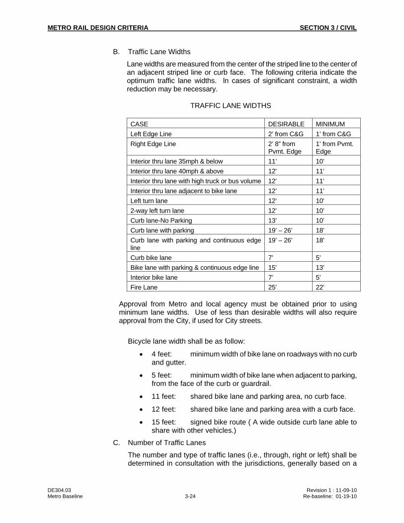
B. Traffic Lane Widths
Lane widths are measured from the center of the striped line to the center of an adjacent striped line or curb face. The following criteria indicate the optimum traffic lane widths. ln cases of significant constraint, a width reduction may be necessary.
TRAFFIC LANE WIDTHS
CASE DESIRABLE MINIMUM
Left Edge Line 2’ from C&G 1’ from C&G
Right Edge Line 2’ 8” from Pvmt. Edge
1’ from Pvmt. Edge
Interior thru lane 35mph & below 11’ 10’
Interior thru lane 40mph & above 12’ 11’
Interior thru lane with high truck or bus volume 12’ 11’
Interior thru lane adjacent to bike lane 12’ 11’
Left turn lane 12’ 10’
2-way left turn lane 12’ 10’
Curb lane-No Parking 13’ 10’
Curb lane with parking 19’ – 26’ 18’
Curb lane with parking and continuous edge line
19’ – 26’ 18’
Curb bike lane 7’ 5’
Bike lane with parking & continuous edge line 15’ 13’
Interior bike lane 7’ 5’
Fire Lane 25’ 22’
Approval from Metro and local agency must be obtained prior to using minimum lane widths. Use of less than desirable widths will also require approval from the City, if used for City streets.
Bicycle lane width shall be as follow:
4 feet: minimum width of bike lane on roadways with no curb and gutter.
5 feet: minimum width of bike lane when adjacent to parking, from the face of the curb or guardrail.
11 feet: shared bike lane and parking area, no curb face.
12 feet: shared bike lane and parking area with a curb face.
15 feet: signed bike route ( A wide outside curb lane able to share with other vehicles.)
C. Number of Traffic Lanes
The number and type of traffic lanes (i.e., through, right or left) shall be determined in consultation with the jurisdictions, generally based on a
METRO RAIL DESIGN CRITERIA SECTION 3 / CIVIL
DE304.03 Revision 1 : 11-09-10 Metro Baseline 3-25 Re-baseline: 01-19-10
traffic analysis which considers projected traffic volumes, LRT vehicle intersection crossings, critical traffic movements and geometric configurations. The lane configuration and signal timings shall, whenever possible, be designed to provide no worse than level of service D at signalized intersections in the P.M. peak hour during at least the year following completion of this project.
D. Parking Lanes
Parking locations shall be determined in consultation with the jurisdictions based on traffic analysis, safety considerations and demand for on-street parking. Twenty-four hour parking prohibition shall be recommended at those locations (e.g. near intersections and at Metro stations) where roadway width is not adequate to provide the necessary number of through lanes. Peak-hour parking prohibition shall be recommended at those locations where traffic analysis shows that the capacity of the traveled way without the parking lane will provide level of service D or worse.
E. Curb Return Radius
Roads
City of Los Angeles 25’
Los Angeles Co. Master Plan Hwy. 35'
Other Los Angeles County 25'
(Larger radii may be warranted where
there is a skewed intersection, narrow
alley, or heavy bus/truck usage.)
Other cities and jurisdictions. Per local jurisdiction
Parking areas 15'
F. Cross Slopes
Concrete and asphalt concrete pavement roads 2%
Aggregate surface pavement 3%
Parking areas 1% min.
6% max.
G. Sidewalks
Maximum cross slope shall be 2%, and match the elevation of existing building(s) finished floor elevation(s), flow away from the building(s)
Minimum slope shall be 0.5%
Federal and State accessibility requirements must be met for sidewalk areas behind and adjoining driveways, alley openings, and pedestrian ramps.
METRO RAIL DESIGN CRITERIA SECTION 3 / CIVIL
DE304.03 Revision 1 : 11-09-10 Metro Baseline 3-26 Re-baseline: 01-19-10
3.7.4 Paving
A. Codes and Standards
All pavement restoration in public streets shall conform to the current specifications and practices of the several jurisdictions and agencies involved.
B. General
Restored pavements shall be of similar materials and shall conform to widths existing prior to transit construction, except that if an existing street is found to be based on obsolete paving materials, such as wood block or brick, replacement will not be in kind, and current specifications and practices will control.
3.7.5 Concrete Bus Pads
Concrete bus pads shall be provided when requested by Metro operations at all bus stops which are constructed or reconstructed adjacent to Metro Rail Projects in conformance with the standards and specifications of the agency having jurisdiction. Continuous concrete pads may be required throughout an entire block in the vicinity of the station entrance when subject to heavy bus traffic or requested by the agency having jurisdiction.
3.7.6 Bus Turnouts
Single bus turnouts shall be a minimum of 10 feet wide with a minimum 50' curb parallel to through traffic lanes and 60' transition entry and 40' transition exit. For each additional pass-through bus berth add 50', and for each additional layover bus berth add 80'. (See bus bay dimensions on Figure 3-19.) For 60’ articulate bus and BRT Bus Turnouts, refer to BRT Design Criteria Figure 3-6.
3.7.7 Traffic Control Devices
A. General
1. Relocation, restoration, and other work involving and traffic signals shall meet the standards of the affected jurisdiction or California Department of Transportation.
2. The Designer shall coordinate the work with the California Department of Transportation and the affected jurisdiction to assure jurisdictional compliance.
B. Codes, Regulations, and Standards
All maintenance, relocations of traffic control devices, temporary or permanent, and restoration of these facilities shall be in accordance with the practices and requirements of the local jurisdiction and Metro. In the case where the local jurisdictions have no standards, the Manual on Uniform Traffic Control Devices shall be followed. Local ordinances include the municipal codes and standard plans of all jurisdictions, and the following reference: City of Los Angeles Special Provisions and Standard Drawings for Installation and Modification of Traffic Signals.
METRO RAIL DESIGN CRITERIA SECTION 3 / CIVIL
DE304.03 Revision 1 : 11-09-10 Metro Baseline 3-27 Re-baseline: 01-19-10
When within the jurisdiction of the City of Los Angeles the City will prepare their own documents and drawings for the traffic control devices to be relocated by the Contractor.
In Los Angeles, all materials used in the installation and/or modification of traffic signal systems shall conform to the latest material specifications, Department of Transportation, City of Los Angeles.
Where the requirements stipulated in this document or any referenced source are in conflict, the more strict requirement shall govern.
Unless specifically noted otherwise, the latest edition of the code, regulation, standard and standard plan that is applicable at the time the design is initiated shall be used. If a new edition or amendment to a code, regulation, standard or standard plan is issued before the design is completed, the design shall conform to the new requirement(s) to the extent practical or required by the governmental agency enforcing the code, regulation, standard or standard plan changed.
C. Traffic Operations
Traffic control devices shall be installed at all at-grade crossings of the LRT tracks in conformance with latest effective version of General Order No. 143 of the Public Utilities Commission of the State of California. See Subsection 12.2.7 of Section 12 (Signaling) regarding protection at grade crossings in the corridor, where gates are to be installed. For operation in the street median, along a side alignment, or in mixed flow with vehicular traffic, Rail Vehicles shall travel at a speed not to exceed the speed permitted by the local vehicle code, but in no case greater than 35 mph. Left turns across the tracks from the parallel roadway shall be prohibited at unsignalized intersections. Although it is not desirable from a safety point of view to allow unprotected left turns across the tracks from a parallel roadway, an exception to this rule may be permitted at locations such as driveways where there is no alternative means of providing access to fronting properties along streets traversed by the Rail Vehicles. At any such locations, where an exception is desired, appropriate design features and/or operational procedures shall be incorporated to minimize conflicts with left-turning vehicles and rail vehicles.
At each signalized intersection, LRT traffic signals shall be provided in addition to the traffic signals controlling motorists at the intersection. These LRT traffic signals shall be standard traffic signal equipment using nonstandard aspects and shall be operated by the same controller as the intersection traffic signals. This shall require special phases and LRT priority capabilities in the traffic signal control equipment.
Controllers shall have the ability to be operated in either an isolated mode (free), or in a coordinated mode. All traffic signals shall be capable of being coordinated with adjacent traffic signals on both the corridor and on cross streets at least 200 feet either side of the rail line. The primary method of coordination shall be fixed cycle length coordination via time-based coordinators, but the provision of master coordination capabilities as part of the monitoring and programming system is considered a definite advantage. Traffic signal preemption capabilities shall be provided at each intersection.
METRO RAIL DESIGN CRITERIA SECTION 3 / CIVIL
DE304.03 Revision 1 : 11-09-10 Metro Baseline 3-28 Re-baseline: 01-19-10
Where rail vehicles pass through or adjacent to signalized intersections without gates, capability for both full and partial rail vehicles priority shall be provided in the traffic signal controller(s). Where crossings are gated, adjacent traffic signals shall be equipped with the capability for normal railroad preemption. At those locations where the "window" concept is to be employed in addition to normal railroad preemption capability, a facility to restrict preemption to prespecified portions of the traffic signal cycle (the window) shall also be provided.
D. Design Guidelines
Type 170 controllers shall be utilized throughout the system unless otherwise required by local jurisdiction.
Where there are existing cable interconnects between traffic signals, they shall be utilized. Otherwise, traffic signals shall be coordinated using time-based coordination.
The traffic signal design and details shall conform to the requirements of the agency having jurisdiction, as shown on that agency's Standard Plan.
Plans shall show location of all new and existing traffic signal equipment and conduits.
Designs shall be coordinated with the agency controlling the intersection.
Consideration shall be given to incorporating a raised median island on the approach to at-grade street crossings where roadway geometry permits, to reduce the opportunity for vehicles to bypass crossing gates in their down position.
Particular attention shall be given to the integration of at grade station platforms into the intersection design.
Pedestrian capacity and control at station access and egress points must be considered. Where pedestrian-actuated traffic signals are provided, they shall be designed to regulate pedestrian crossings of the LRT and/or railroad tracks, as well as of the adjacent roadways. Pedestrian push buttons shall be provided to actuate the pedestrian signals. All pedestrian signals shall display international symbols. An appropriate pedestrian refuge area shall be provided at either end of the crosswalk, including the area between LRT tracks in at-grade station areas.
Traffic signal indications shall be provided for each approach to an intersection at a minimum of two locations (on two poles).
Where left turns or right turns across the LRT tracks are to be controlled by a traffic signal, a protected turn phase shall be provided.
Pedestrian traffic signals shall be provided at all signalized intersections.
METRO RAIL DESIGN CRITERIA SECTION 3 / CIVIL
DE304.03 Revision 1 : 11-09-10 Metro Baseline 3-29 Re-baseline: 01-19-10
Specially designed signal equipment (such as special poles and standards) shall be replaced in kind if they are removed or modified as a result of this project. (At the discretion of the agency having jurisdiction).
3.7.8 Street Signing and Striping
A. General
1. After consultation with Metro, the Designer shall coordinate with concerned authorities to assure compatibility of street signing with transit construction staging.
2. Street striping and restriping plans may be done by the local jurisdiction. Otherwise the Designer will prepare the plans, subject to the approval of the local jurisdiction
B. Codes and Standards
All work involving relocation, restoration, and temporary installation of street signing shall conform to current standards of local jurisdiction and of the California Department of Transportation.
3.7.9 Parking Meters
A. General
Within their jurisdictions the affected agencies will remove and restore meter heads; the Contractor shall remove, store, and reinstall posts.
B. Codes and Standards
Does not apply, since work will involve only removal and restoration of existing facilities.
3.7.10 Ramps and Curb Cuts
Wheelchair ramps shall be provided in accordance with the following:
1) Restore or replace any existing ramps.
2) Provide ramps at intersections where any of the curb returns are modified as part of the LRT Projects and provide direct access to stations.
The design of curb cuts and ramps shall be in accordance with the applicable provisions of the Americans with Disabilities Act (ADA) and Title 24, California Code of Regulations Part 2, "Regulations for the Accommodation of the Disabled in Public Accommodations."
Location of ramps and curb cuts in public space shall be obtained from the local governing jurisdiction and shall be in accordance with the ADA and Title 24.
3.7.11 Sidewalks
Sidewalks shall be in accordance with the standards of the agency having jurisdiction.
METRO RAIL DESIGN CRITERIA SECTION 3 / CIVIL
DE304.03 Revision 1 : 11-09-10 Metro Baseline 3-30 Re-baseline: 01-19-10
3.7.12 Ventilation Grating Opening
Ventilation grating openings shall be located to minimize any adverse effect on existing features of landscaping, improvements, and environment. Such gratings may be located either in raised median strips, Metro property adjacent to public R.O.W. or in an approved location immediately behind the street curbs, provided the width of grating does not exceed 50 percent of the sidewalk width or 5 feet, whichever is greater, but must maintain a minimum clear level concrete distance of 48 inches behind the metal portions of the grate. Where possible, gratings will be located outside of the far tangent points at street intersections and will not be located in any crosswalk area. Covered openings, such as mechanical access openings, may be permitted in sidewalk. Sidewalk and street gratings for subway vent and fan shafts shall be steel grating with bar sizes and spaces to be designed considering the type of traffic to be imposed.
3.7.13 Vaults
A. General
1. The Designer shall determine which vaults will be affected by transit construction. Details shall show the portion of each vault to be excavated; new walls required to permit continued use of vaults outside construction limits; new walls to accomplish complete abandonment of vaults, where required; the work required to restore vaults, including delivery chutes and freight elevators and the area available for permanent occupancy by the original owner upon completion of transit facilities.
2. The Designer shall determine what goods or facilities must be removed from the vault; how deliveries will be made to properties when existing vault entrances must be abandoned; and the time required to take each of the above enumerated steps. This information shall be forwarded to Metro at the earliest practical date to avoid possible construction delay, and Metro will arrange for permission to occupy the vault and make the necessary alterations.
3. All vaults shall be designed to be “watertight”, with no water intrusion.
B. Codes and Standards
All remodeling, abandonment, or other work involving private vaults extending from adjoining buildings into public space shall conform to the rules, regulations and practices of the jurisdictions involved.
3.7.14 Driveways
Driveway minimum and maximum widths and numbers shall be in accordance with the standards of the agency having jurisdiction.
3.7.15 Landscape Areas and Street Trees
A. General
METRO RAIL DESIGN CRITERIA SECTION 3 / CIVIL
DE304.03 Revision 1 : 11-09-10 Metro Baseline 3-31 Re-baseline: 01-19-10
1. Street trees and landscaped areas shall be preserved wherever practicable. The Designer shall indicate the trees to be removed and replaced, and those that are to be protected. Subject to local jurisdiction, street trees are to be replaced on and one-for-one basis with 36" box standard. The tree species shall be designated by the local jurisdiction. Tree location shall be coordinated with the location of other sidewalk features, such as streetlights, fire hydrants, station appurtenances, and underground utilities and basements.
2. If trees cannot be maintained during construction, existing landscaped areas shall be restored after construction to the original condition to the extent possible, with street trees to be replaced.
B. Codes and Standards
All work involving street trees and landscaped areas shall conform to specifications, criteria, and practices of the agencies having jurisdiction.
3.7.16 Exit Hatches
A. Hatches in driveways and parking areas: Hatches shall not be located in driveways. Hatches shall not be located in parking areas unless protected by bollards and provided with adequate protected egress lanes to a public way.
Hatches shall be installed at a minimum six inches higher elevation than the surrounding grade level. Elevation of the egress lanes, to a public way, to match elevation of Exit Hatch and public way.
B. Hatches Installed in Sidewalks: Hatches to be designed so that the hatch doors are installed in one plane generally conforming to sidewalk cross slopes. Edges around the exit hatch shall not cause tripping hazard to the pedestrians.
Locate edge of Exit Hatches minimum of 1'-6" from face of curb.
3.8 DRAINAGE
3.8.1 General
Storm drainage system design shall be in conformance with the requirements of the agency having jurisdiction.
3.8.2 Hydrology
A. Surface and Aerial Construction
Hydrology shall be based upon standards and methods of computation used by the Los Angeles County Department of Public Works and the City of Los Angeles Bureau of Engineering, Engineering Design Standards.
B. Underground Sections in Earth
Drainage for underground sections in earth shall be designed to exclude groundwater and shall be based on the formula:
q = a + L
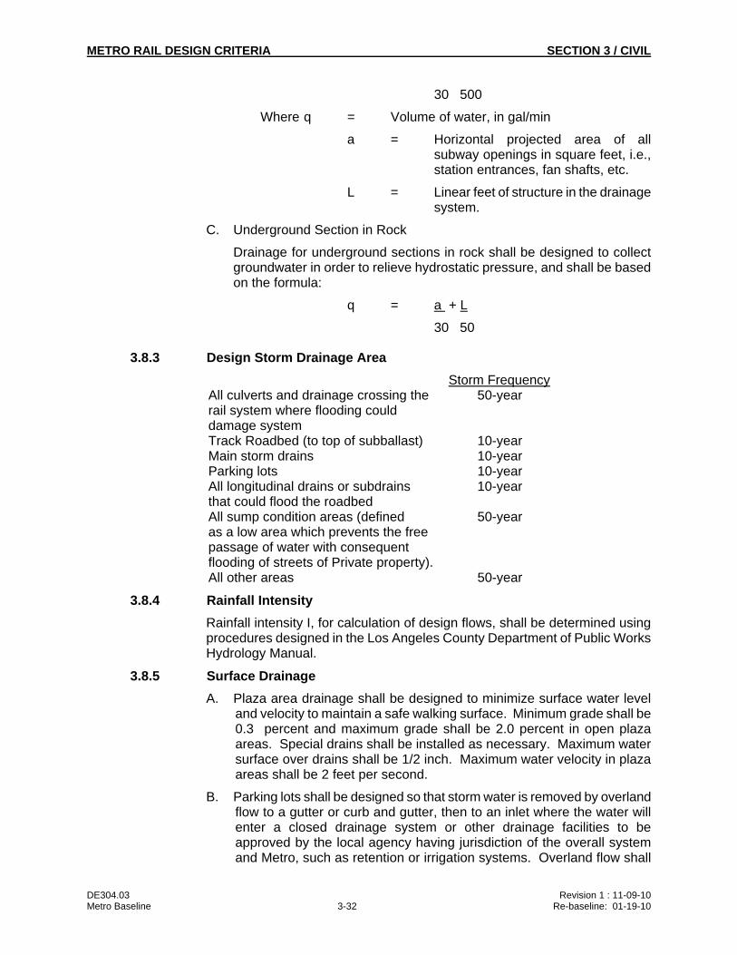
METRO RAIL DESIGN CRITERIA SECTION 3 / CIVIL
DE304.03 Revision 1 : 11-09-10 Metro Baseline 3-32 Re-baseline: 01-19-10
30 500
Where q = Volume of water, in gal/min
a = Horizontal projected area of all subway openings in square feet, i.e., station entrances, fan shafts, etc.
L = Linear feet of structure in the drainage system.
C. Underground Section in Rock
Drainage for underground sections in rock shall be designed to collect groundwater in order to relieve hydrostatic pressure, and shall be based on the formula:
q = a + L
30 50
3.8.3 Design Storm Drainage Area
Storm Frequency All culverts and drainage crossing the 50-year rail system where flooding could damage system Track Roadbed (to top of subballast) 10-year Main storm drains 10-year Parking lots 10-year All longitudinal drains or subdrains 10-year that could flood the roadbed All sump condition areas (defined 50-year as a low area which prevents the free passage of water with consequent flooding of streets of Private property). All other areas 50-year
3.8.4 Rainfall Intensity
Rainfall intensity I, for calculation of design flows, shall be determined using procedures designed in the Los Angeles County Department of Public Works Hydrology Manual.
3.8.5 Surface Drainage
A. Plaza area drainage shall be designed to minimize surface water level and velocity to maintain a safe walking surface. Minimum grade shall be 0.3 percent and maximum grade shall be 2.0 percent in open plaza areas. Special drains shall be installed as necessary. Maximum water surface over drains shall be 1/2 inch. Maximum water velocity in plaza areas shall be 2 feet per second.
B. Parking lots shall be designed so that storm water is removed by overland flow to a gutter or curb and gutter, then to an inlet where the water will enter a closed drainage system or other drainage facilities to be approved by the local agency having jurisdiction of the overall system and Metro, such as retention or irrigation systems. Overland flow shall
METRO RAIL DESIGN CRITERIA SECTION 3 / CIVIL
DE304.03 Revision 1 : 11-09-10 Metro Baseline 3-33 Re-baseline: 01-19-10
be a minimum of 0.3 percent grade, and shall not run for more than 75 feet before being intercepted by a drainage structure such as a gutter or a drain. The maximum flow (flood width) in the gutter in a parking area shall not exceed 12 feet before being collected in a drainage system. Best Management Practices (BMP) shall be incorporated to satisfy SUSMP requirements for parking lots of 5,000 square feet or more, having 25 or more parking spaces and exposed to storm water runoff.
C. Street drainage shall be designed so water surface remains below top of curb and does not flow more than 1/2 inch deep in the traveled way. The traveled way being the lane that begins 8 feet away from the face of curb. Water surface elevation shall be controlled by adding catch basins as necessary.
D. A storm drainage system shall be provided along all trackways and at all yards. The system normally consists of a combination of graded subgrade areas and perforated self-cleaning subdrains connected to the necessary laterals, collectors, and outfall structures. A system of ditches, catch basins, and storm drain pipes shall be designed to directed surface runoff away from all track areas and also to handle flow from the subdrain and any roof drain systems. In no case shall a storm drain flow into a subdrain.
1. Yard trackwork areas shall be underlain by a 6" minimum layer of semi-impervious subballast properly compacted and graded at a minimum slope of 24:1 to the subdrains. Open surface track and material storage areas also shall be covered with an 8" layer of semi-impervious compactable material and shall be graded to area drains at a minimum slope of 24:1.
2. The drainage system shall contain the following minimum slopes:
Subdrains -0.5% Laterals -0.3% Main Collectors -0.25% Ditches -0.25%
3. Cleanouts shall be provided at the terminus of each subdrain. Manholes shall be provided at maximum intervals of 300' on the laterals and main collectors, or a junction, on angle points greater than 10 degrees in order to facilitate the maintenance of the drainage system. The individual subdrain runs shall not be longer than 300'.
3.8.6 Drainage Structures
A. Drainage Structures, except for parking lots, shall be designed special structures which satisfy the conditions. Use of agency standards is permissible.
B. Drainage structures for parking lots shall be selected from the standard storm drain details of the jurisdiction in which the parking lot is to be constructed. Inlet structures should not be located adjacent to bus pads, on-site bus stops, or where patrons would normally be picked up or dropped off by vehicles other than Metro buses.
METRO RAIL DESIGN CRITERIA SECTION 3 / CIVIL
DE304.03 Revision 1 : 11-09-10 Metro Baseline 3-34 Re-baseline: 01-19-10
C. A sufficient number of inlets shall be provided to intercept the surface drainage. Inlets on grade shall be designed to intercept 85 percent or more of the design flow. Inlets in sump areas shall be designed to intercept 100 percent of the design flow. The amount of flow intercepted by an individual inlet shall be determined by the procedures outlined in the Federal Highways Administration's Hydraulic Engineering Circular No. 12 (HEC-12), entitled "Drainage of Highway Pavements" dated March 1984, and HEC-22 entitled "Urban Drainage Design Manual" dated August 2001. Where local agencies have jurisdiction, inlets shall be designed in accordance with the practices of the local agency having jurisdiction.
3.8.7 Storm Drains
A. Closed Conduit
1. Hydraulic Design
Pipe sizes shall be selected based on the criteria for Hydraulic design: Closed Conduits, in the Los Angeles County Flood Control District Hydraulic Design Manual. Main line minimum size shall be 24 inches and catch basin connector pipe minimum size shall be 18 inches. For storm drains run greater than 100 feet : the minimum size of reinforced concrete pipe (RCP) used shall be 24”. When Metro construction requires the connection of a new storm drainage system to an existing system, the Designer shall check the hydraulics of the existing system, including the new flows, to determine adequacy and grades of the new drainage system. The Designer shall also check to see that the entrances and vent shafts and emergency stair exits are not subject to inundation by the Q50 frequency floods.
2. Materials
All underground storm drains shall be reinforced concrete pipe (RCP). RCP located in track R.O.W. shall be provided with cathodic protection as necessary. High Density Polyethylene Pipe (HDPE) and Polyvinyl Chloride Pipe (PVC) may be used where its use is approved by the governing agency. Drain connections in structural walls and floors shall be Ductile Iron Pipe (DIP). Steel pipe shall not be used in the permanent underground drainage system.
3. Friction Coefficient
Material Manning "n" Ductile Iron Pipe (DIP) 0.014 Polyvinyl Chloride Pipe (PVC) 0.012 Reinforced Concrete Pipe (RCP) 0.013 High Density Polyethylene Pipe (HDPE) 0.011
4. Structural Considerations
Class of pipe and bedding shall be determined from foundation conditions, depth of cover, and loading conditions.
B. Open Channel
METRO RAIL DESIGN CRITERIA SECTION 3 / CIVIL
DE304.03 Revision 1 : 11-09-10 Metro Baseline 3-35 Re-baseline: 01-19-10
1. Open channel design shall be based on the Criteria for Hydraulic Design: Open Channels, of the Los Angeles County Flood Control District Hydraulic Design Manual.
2. Materials and Friction Factors
Below is a list of the treatments acceptable for open channel storm drainage. Accompanying each treatment is the roughness coefficient to be used in the solution of the Manning Formula and the maximum allowable velocity. The Designer shall submit for approval by Metro other channel alternatives.
Material
Manning "n"
Max. Allowable Velocity ft/sec
Concrete 0.013 20 Earthen Channel (clay) 0.020 4 Earthen Channel (rough,) 0.030 4
For other conditions refer to an appropriate hydraulic reference (e.g. King's Handbook of Hydraulics, etc.).
3.8.8 Flood Control
The design of the transit system shall include an analysis of the potential for flooding in the vicinity of transit facilities. The analysis shall consider such flood sources as storm surge flooding of rivers, flood control channels, storm drainage systems, and surface flows. The Designer shall perform the analysis early in the design and submit the analysis, together with recommendations for protecting the transit facilities from flooding, to Metro for approval. Proposed protection shall address all openings into the transit facilities, including station entrances, vent shafts, emergency exits, access hatches and utility connections.
3.9 SITE WORK AND PARKING FACILITIES
3.9.1 General
A. This chapter establishes criteria and standards for the design of streets, parking lots, parking structures, pedestrian facilities, and driveways, including signage, marking and striping, all of which are to be maintained by Metro. Roadway design in public right-of-way and for railroad crossings at-grade shall be in conformance with the specification and design guidelines of the affected local jurisdiction. (See 3.7, STREETS)
B. Basic Goals
The basic goals of this chapter are:
1. To provide for the safety of Transit Patrons while arriving, waiting at or departing from the station site.
2. To establish convenient traffic circulation patterns for vehicular and pedestrian movement.
METRO RAIL DESIGN CRITERIA SECTION 3 / CIVIL
DE304.03 Revision 1 : 11-09-10 Metro Baseline 3-36 Re-baseline: 01-19-10
3. To provide parking facilities that are safe, convenient, attractive, and easily maintained.
4. To provide for the reconstruction of local roads and streets disturbed by Metro construction
3.9.2 Traffic Modes
A. Patrons will arrive at, and depart from stations in as many as seven basic modes, as follows:
Rail Pedestrian Bicycle Bus-and-Ride Kiss-and-Ride Motorcycle Park-and-Ride.
B. Facilities to park bicycles, motorcycles, and cars as well as off-street Bus-and-Ride and Kiss-and-Ride facilities will be incorporated at selected stations.
C. The maximum possible separation between modes of transportation shall be provided.
3.9.3 Metro System Streets Design Elements
A. Vehicular Entrances to Station Sites
Vehicular entrances to station sites shall be in accordance with the following:
1. Vehicular entrances from public streets shall be from minor streets where possible, with provisions for sufficient stacking space provided at intersections with major streets.
2. Entrances, where feasible, should be so located that a vehicle approaching the station from any direction, missing one entrance, will find a second available without circuitous routing.
3. The number of vehicular entrances along any one street shall be minimized. Entrances shall be at least 150 feet apart. Sufficient number of entrances shall be provided so that the volume per lane entering station sites does not exceed 300 vehicles per hour.
4. Wherever the volume of traffic entering or exiting a public street increases the street traffic volume beyond the street capacity, the addition of auxiliary lane(s) shall be considered.
B. Traffic Lanes
All roadways other than those used mainly for service or maintenance purposes shall have at least one traffic lane for each direction of travel. The number of traffic lanes provided on these roadways shall be sufficient so that the vehicular volume per lane does not exceed 300 vehicles per hour. Where these roadways are one-way and have only a single traffic
METRO RAIL DESIGN CRITERIA SECTION 3 / CIVIL
DE304.03 Revision 1 : 11-09-10 Metro Baseline 3-37 Re-baseline: 01-19-10
lane, the traveled-way width shall be 20 feet with either a gutter or shoulder on each side giving a clear distance of at least 24 feet between constraints. Lane width for roadways of more than one lane, exclusive of gutter or shoulder width, should be 12 feet but shall be not less than 11 feet.
C. Parking Lanes and Curb Loading Zones
1. Placement of loading zones on access roadways shall reflect the following order of preference with respect to proximity of the loading zone to the station concourse:
Buses Passenger cars (Kiss-and-Ride) Taxi reservoirs
2. Parking on Transit System roadways preferably shall be parallel to the curb. Lane width prescribed herein for parking and loading zones includes the gutter width.
D. Loading Zones for Buses and Taxis
1. The required bus (or taxi) design capacity for a station shall be determined by the Designer based on the individual requirements for each station.
2. Loading zones for buses and taxis shall be located to provide the most direct and safest intermodal transfer.
3. The following designs show standard layout for various types of bus loading zones.
a. Recessed Bus Bays: Where the volume of passenger cars or buses warrants on roads used jointly by cars and buses, the bus loading zone shall be recessed from the through traffic lane.
(1) Recessed bus bays shall be designed parallel to and close enough to the curb so that passengers may enter and leave any door by an easy step to the curb. Upon leaving, the merging lane will enable the bus an easy re-entry into the through traffic lane.
(2) The loading zone shall have a 10-foot wide lane, and the total length for a two-bus loading area should be 120 feet long with a 40-foot tapered section at each end. For each additional bus required, an additional 80-feet length shall be added at curbside.
b. Parallel-to-Curb Bus Bays: Parallel to curb base shall have 10-foot-wide lanes and a length of 80 feet.
c. Sawtooth Bus Bays: Sawtooth bus bays will reduce the length of loading zone, but will increase the width of roadway. The critical movement in this layout is the operation of moving a bus out and around a parked bus at the loading zone.
METRO RAIL DESIGN CRITERIA SECTION 3 / CIVIL
DE304.03 Revision 1 : 11-09-10 Metro Baseline 3-38 Re-baseline: 01-19-10
(1) The minimum roadway width is determined as follows:
23 ft - 8 in. Clearance path of bus 2 ft - 0 in. Additional clearance 3 ft - 4 in. High point 29 ft - 0 in. Nominal roadway width
(2) The nominal roadway width is the average of the high and low points of the sawtooth and allows a direct comparison with the parallel-to-curb bus bays.
d. 60’ articulated recessed bus bays and parallel-to-curb bus bays shall refer to BRT Design Criteria Figure 3-6. In addition, sawtooth bus bays for 60’ articulated buses shall refer to BRT Design Criteria Figure 3-5.
e. Taxi zones shall have a minimum lane width of 8 feet. Parking spaces for taxis shall be 25 feet long and shall be no closer than 20 feet to a crosswalk.
f. Passenger Drop-off and Loading Zones for Disabled
(1) Shall be a minimum of 20 feet in length of vehicle pull-up space
(2) Minimum 20’ x 5’ access aisle adjacent and parallel to the vehicle pull-up space
(3) Access aisle shall connect directly to an accessible route
(4) Minimum 114’ vertical clearance at accessible drop-off and loading zones and along at least one vehicle access route to the zone
(5) The zone must be signed “PASSENGER LOADING ZONE ONLY” and include the International Symbol of Accessibility in white on a dark blue background (CA Title 24 1131B.1)
3.9.4 Site Work Criteria
A. Grading
1. All areas of proposed construction shall be cleared, grubbed, and stripped. Areas disturbed by construction shall be protected by an erosion control system. Methods of erosion control to be considered include jute matting or burlap, application of chemical materials to stabilize surface areas, and application of gravel or coarse rock. Storm water pollution and prevention program (SWPPP) shall conform to the rules, regulations and practices of the agencies having jurisdiction. Seeding and sodding as a form of erosion control, shall be used on a case by case basis.
2. Construction of fills in areas that receive loading shall be a controlled fill. The method and device of construction and rework of existing soil shall be as recommended by the geotechnical consultant.
B. Grades
METRO RAIL DESIGN CRITERIA SECTION 3 / CIVIL
DE304.03 Revision 1 : 11-09-10 Metro Baseline 3-39 Re-baseline: 01-19-10
1. Parking lots
a. Driveway Slopes and Ramps
20% maximum slope on driveway or ramp.
10% maximum cross slope of a driveway or ramp.
Transition slopes are required when the slope of the driveway or ramps exceeds 12%
b. General
5% maximum slope in any direction in a parking stall.
6% maximum slope in any direction in a traveled area.
2% desirable slope in any direction.
0.3% minimum slope in any direction.
c. Comply with ADA criteria regarding slopes at parking spaces and access aisles designated for accessible parking. Accessible parking spaces shall be located at an optimum location within the parking lot, to provide easy access to the station.
Maximum 6%
2. Metro Property Streets
Maximum 6%
Desirable 5%
Minimum 0.5%
Desirable 1%
Cross-slope 2%
Crown cross section except on curves where 2% continuous cross-slope toward center of curve may be used.
3. Maximum Grade Differential for Metro Property Streets
Crest Vertical Curve 9%
Sag Vertical Curve 6.5%.
NOTE: Crest and Sag Curves at top and bottom of ramps without parking may exceed these differentials, but must use a vertical curve 20 feet in length or more.
4. All Other Streets
Refer to Applicable Jurisdiction
C. Design Speeds
1. In parking lots - not applicable
2. On Metro Property streets - 30 mph.
3. All other streets - Refer to applicable Jurisdiction
METRO RAIL DESIGN CRITERIA SECTION 3 / CIVIL
DE304.03 Revision 1 : 11-09-10 Metro Baseline 3-40 Re-baseline: 01-19-10
D. Clearances
1. Metro Property Streets
Vertical, 14 feet 6 inches
Horizontal, 2 feet 6 inches from face of curb to fences, light standards, and pedestrian barriers.
2. Parking Lots
Vertical, 7 feet 0 inches (with height restrictions noted)
Horizontal, 2 feet 6 inches.
Minimum 114” vertical clearance provided to van accessible parking spaces
E. Vertical Curves on Metro Property Streets
1. Crest Curves - Lmin = 28 A
2. Sag Curves - Lmin = 35 A.
Where: Lmin = minimum vertical curve length
A = Algebraic difference in grades
No vertical curves shall be less than 20 feet.
F. Curb Returns
Parking Lots and Areas
1. For cabs, 20 feet (Inside Radius)
2. For buses, 30 feet minimum (inside radius), 50 foot minimum (outside radius clear).
3. For passenger cars 15.3 feet minimum (inside radius), 25.8' minimum (outside radius clear).
G. Sight Distance at Intersections
To comply with "A Policy on Geometric Design of Rural Highways," current edition, published by the American Association of State Highways and Transportation Officials (AASHTO).
H. Curbs and Gutters
All Transit Property streets and parking lots shall have curbs and gutters. Curbs shall be 6-inch-high, barrier-type, with sloping face of 1 inch horizontal to 6 inches vertical. Gutters shall be 24 inches, sloped to roadway or parking lot cross-slope and grade. Curbs and gutters shall be cast-in-place Class A concrete, and shall be in compliance with City or Public Work Construction standard plans.
I. Side Slopes
Cut-and/or-fill-slopes shall be as flat as possible, and shall not exceed a slope of 2:1 (horizontal to vertical) or as recommended by the geotechnical consultant. Tops of cut slopes shall be rounded.
J. Drainage
METRO RAIL DESIGN CRITERIA SECTION 3 / CIVIL
DE304.03 Revision 1 : 11-09-10 Metro Baseline 3-41 Re-baseline: 01-19-10
Drainage runoff shall be calculated in accordance with:
1. Surfaces shall be sloped to drain away from areas where pedestrians walk.
2. Catch basins are not to be located in pedestrian walkways.
3.9.5 Traffic Control Devices
A. General Criteria
The paragraphs that follow prescribe the criteria to be used for signs and for pavement and curb markings in streets, parking lots, and parking structures. See Section 3.3.12 for traffic signal requirements. Curb markings, signs and striping used on Metro-owned streets and parking lots shall be standard facilities as required by the latest edition manual on Uniform Traffic Control Devices.
The application of any traffic control device shall:
1. Fulfill an important need
2. Be located in such a manner as to command attention and provide adequate time for response
3. Command respect and gain compliance
4. Convey a clear, simple, and appropriate message
5. Complement a good design
B. Signs
1. Signs shall be displayed only for the specific purpose and under the specific conditions prescribed in these criteria.
2. Signs shall not be used to confirm well known or universally recognized rules of the road. They shall be used where special regulations apply at specific places or at specific times only, or where hazards are not self-evident. Care shall be taken not to install too many signs, especially those of the regulatory or warning types, which, if used too excessively, tend to lose effectiveness. On the other hand, a frequent display of directional signs will not lessen their value.
3. Signage per latest edition of Uniform Traffic Control Devices, and California MUTCD 2003 Rev. 1, as amended for use in California.
C. Striping Codes and Standards
Paint materials, striping details, including standard pavement marking, striping with markers, striping transitions and crosswalk detail are to be obtained from standard plans and drawings of each jurisdiction where appropriate and shall comply with current federal and state accessibility regulations. Where local standards are not available, the latest edition of Manual on Uniform Traffic Control Devices and Caltrans Traffic Manual shall be used as guides to pavement marking.
METRO RAIL DESIGN CRITERIA SECTION 3 / CIVIL
DE304.03 Revision 1 : 11-09-10 Metro Baseline 3-42 Re-baseline: 01-19-10
3.9.6 Parking General (See Figures 3.8 through 3.21)
For parking lot design within the station area, the designer shall consider providing adequate designated parking stalls for Metro security personnel and those engaged in revenue pickup from TVMs. The identified location for security parking shall be safe and close to the station entrance.
A. Parking Stall Dimensions
1. Stall Angle (Parallel) 45o 60o 90o Stall Dimension Normal Car - width 9.0 ft 9.0 ft 9.0 ft 9.0 ft
- length 22.0 ft 18.0 ft 18.0 ft 18.0 ft Disabled spaces
- width 14.0 ft 14.0 ft 14.0 ft - length 18.0 ft 18.0 ft 18.0 ft
Disabled Van Space 45o 60o 90o - Width 17.0 ft 17.0 ft 17.0 ft - length 18.0 ft 18.0 ft 18.0 ft Small Car - width 8.0 ft 8.0 ft 8.0 ft
- length 15.0 ft 15.0 ft 15.0 ft Clear Aisle - width (Roadway) 13.0 ft 19.0 ft 27.0 ft
(one way) (one way) (two way)
2. The criteria relating to small-car stalls shall be based on the specifications and design guidelines of the local agency responsible for locale parking lot layout.
3. Disabled parking spaces shall be provided in accordance with Title 24, Section 2-7102, California Code of Regulations (CCR) (refer to Caltrans Standard Plan Accessible Parking Off-Street). Disabled parking spaces shall be located as near as practical to a primary entrance to a facility (building, station entrance, or boarding platform). The space shall be located so that a disabled person does not have to wheel or walk behind parked cars other than his/her own. Pedestrian ways shall be provided so as to ensure an accessible pathway from each such parking space to the facility; walks and sidewalks shall conform to Title 24 Sec. 2-3323. When parking is provided for patrons, employees, or visitors, the minimum number of disabled spaces required is as follows:
METRO RAIL DESIGN CRITERIA SECTION 3 / CIVIL
DE304.03 Revision 1 : 11-09-10 Metro Baseline 3-43 Re-baseline: 01-19-10
Total No. Parking Spaces No. disabled Parking Space Required
1 -to 25 1 26 - 50 2 51 - 75 3 76 - 100 4 101 - 150 5 151 - 200 6 201 - 300 7 301 to 400 8
401 to 500 9
501 to 1000 2% of total
1001 and over 20 plus 1 for each 100 over 1000
One (1) Van Parking Space for every 8 disabled spaces
The requirement in Title 24, shall also be met for other factors such as signage, minimum dimensions of accessible spaces, slope of parking surfaces, and entrances/vertical clearances for parking structures.
B. Multilevel Parking Structures
1. Ground levels shall contain entrances and exits, reservoir areas and internal ramps, and locations for obtaining parking tickets on entry and toll booths on exit, as well as parking areas. Kiss-and-Ride areas shall be located outside the parking structure unless this is impossible. Upper levels and/or underground levels shall contain only ramps and as many parking stalls as possible.
2. Traffic circulation within parking structures shall be designed to minimize vehicular travel distances and number of turns. A left hand traffic pattern is preferred.
3. Columns will be located to provide uniform spans for the structure as much as is possible. Columns must not encroach on the clear dimensions noted for cars, unless a small-car stall can be created. Columns shall be located not closer than every third stall.
4. Where site conditions permit, adjoining street grades shall be used to minimize the need for ramps between parking levels.
5. Internal ramps shall be placed as far as practicable from entrances and exits. The ramps shall be so placed that they do not constitute a direct and natural path for pedestrian travel to the station concourse. Internal ramps shall be designed for one-way travel. Parking stalls shall not be located on curved internal ramps.
6. External ramps may be used where appropriate. The ramps shall be designed for one-way travel and shall merge directly into, or diverge directly from streets. Whenever practicable, a grade separation of pedestrians and vehicles shall be provided where external ramps cross pedestrian walkways. Parking stalls shall not be located on external ramps.
METRO RAIL DESIGN CRITERIA SECTION 3 / CIVIL
DE304.03 Revision 1 : 11-09-10 Metro Baseline 3-44 Re-baseline: 01-19-10
7. The design capacity of ramps shall be 200 vehicles per lane per hour.
8. Ramp grades shall be kept as low as practicable, and excluding areas of transition, shall not exceed 6 percent on ramps with parking or 12 percent on ramps without parking.
9. Traveled ways, other than parking aisles and ramps, shall be 24 feet wide for two-way travel and 16 feet wide for one-way travel. The minimum vehicular inside turning radius shall be 16 feet, and the minimum outside turning radius shall be 26 feet.
10. Bicycle lockers for long term rental shall be provided at ground level close to station entrance but not located immediately next to queuing areas.
3.9.7 Kiss-and-Ride Facilities
A. Capacity
The required design capacity for a station shall be determined by the Designer and will be based on the individual requirements of each station.
B. Location
Location of Kiss-and-Ride facilities shall be in accordance with the following:
1. Parking facilities located off-street, in a parking lot, shall be as near to the station concourse entrances as practicable and shall be physically separated so as not to appear as an integral part of long-term parking areas within the parking lot or parking structure.
2. Kiss-and-Ride facilities shall be located off-street, as near to the main station entrance as practical, and shall be physically separate from long-term parking areas and Bus-and-Ride facilities. Loading is preferred on the right-hand side of the car. The location should, if possible, be such that a driver can view the station entrance to see an exiting passenger for whom he is waiting.
3. An accessible parking area for persons waiting to pick up persons with disabilities shall be provided as required by installing appropriate pavement markings and signs.
4. All Kiss-and-Ride parking spaces shall be delineated by signs or curb markings as being limited to short-term use.
5. Kiss-and-Ride parking stalls shall be 9 feet wide and preferably at a 60 degree angle.
3.10 CORROSION CONTROL
3.10.1 Introduction
This section describes the design criteria necessary to provide corrosion control measures for dc-powered rail transit systems that use the running rails as the negative return path. Corrosion control systems are required to prevent premature corrosion failures on transit system fixed facilities and
METRO RAIL DESIGN CRITERIA SECTION 3 / CIVIL
DE304.03 Revision 1 : 11-09-10 Metro Baseline 3-45 Re-baseline: 01-19-10
other underground structures. Such measures, or systems, will minimize stray current levels and their effects on underground and above-grade structures. Corrosion control systems must be economical to install, operate and maintain.
A. Scope
Corrosion control design criteria shall encompass all engineering disciplines applied to the project. The criteria are separated into three areas: soil corrosion, atmospheric corrosion and stray current corrosion. The design criteria for each of these categories and their implementation shall meet the following objectives:
1. Realize the design life of system facilities by avoiding premature failure caused by corrosion.
2. Minimize annual operating and maintenance costs associated with material deterioration.
3. Provide continuity of operations by reducing or eliminating corrosion-related failures of systems and subsystems.
4. Minimize detrimental effects to facilities belonging to others as may be caused by stray earth currents from transit operations.
B. Codes, Standards and Regulations
Corrosion control systems shall conform to the requirements of the codes (including ordinances), regulations (including general rules and safety orders), and standards and recommended practices in publications by the organizations listed herein.
Where the requirements, stipulated in this document or any referenced source are in conflict, the more stringent requirement shall govern.
Unless specifically noted otherwise herein, the latest edition of the code, regulation and standard that is applicable at the time the design is initiated shall be used. If a new edition or amendment to a code, regulation or standard is issued before the design is completed, the design shall conform to the new requirement(s) to the extent practical or required by the governmental agency enforcing the code, regulation or standard changed.
1. NACE International (National Association of Corrosion Engineers)
2. Steel Structures Painting Council (SSPC)
3. National Fire Protection Association (NFPA)
4. American National Standard Institute (ANSI)
5. National Electrical Manufacturers Association (NEMA)
6. American Society for Testing and Materials (ASTM)
7. State of California, Department of Transportation (CALTRANS) Standard Specifications
8. Standard Specifications for Public Works Construction (SSPWC)
METRO RAIL DESIGN CRITERIA SECTION 3 / CIVIL
DE304.03 Revision 1 : 11-09-10 Metro Baseline 3-46 Re-baseline: 01-19-10
9. American Institute of Steel Construction (AISC), Code of Standard Practice for Steel, Buildings and Bridges
10. California Building Code (CBC)
11. California Underground Storage Tank Regulations, Title 23
12. Environmental Protection Agency (EPA)
13. American Association of State Highway and Transportation Officials (AASHTO)
14. U.S. Department of Transportation, Regulations for the Transportation of Natural (or other) Gas by Pipeline, Parts 191 and 192, Title 49
15. U.S. Department of Transportation, Regulations for the Transportation of Liquids by Pipeline, Part 195, Title 49
16. California Code – Chapter 5.5: The Elder Pipeline Safety Act of 1981 [51010.-51019.1]
17. Applicable local and municipal codes.
3.10.2 General
A. Requirements
1. Soil Corrosion Control
Criteria in this category apply to systems or measures installed to mitigate corrosion caused by soils and groundwater. Designs shall be based on the corrosive characteristics of the soils as documented in pre-design evaluation reports, and from actual on-site measurement as necessary.
2. Stray Current Corrosion Control
Criteria in this category apply to measures installed with the traction power system and trackwork to ensure that stray earth currents do not exceed maximum acceptable levels. These levels are based on system characteristics and the characteristics of underground stray current corrosion control structures as documented in pre-design reports.
These stray current corrosion control criteria apply to measures installed with fixed facilities, and possibly to facilities belonging to others. They are based on anticipated stray earth current levels and the characteristics of fixed facilities and other buried structures. Designs shall be based on conditions documented in pre-design evaluation reports.
3. Atmospheric Corrosion Control
Criteria in this category apply to systems or measures installed to mitigate corrosion caused by local climatological conditions and air pollutants. Designs shall be based on conditions documented in pre-design evaluation reports and other requirements of Section 2, Environmental Considerations.
METRO RAIL DESIGN CRITERIA SECTION 3 / CIVIL
DE304.03 Revision 1 : 11-09-10 Metro Baseline 3-47 Re-baseline: 01-19-10
B. System Interfaces
Corrosion control engineering shall be interfaced and coordinated with the other disciplines, including mechanical, utility, electrical, civil, structural, trackwork, electrification, signaling, and communications designs. The corrosion control discipline shall be coordinated throughout the design, installation and startup of the system.
3.10.3 Soil Corrosion Control
A. General
This section provides criteria for the design of systems and measures to prevent soil and groundwater corrosion on transit system fixed facilities. Designs shall be based on achieving a minimum 50-year design life for buried structures through consideration of the factors given below.
1. Materials of Construction
All buried pressure and nonpressure piping and conduit shall be non-metallic, unless metallic materials are required for specific engineer-ing purposes. Aluminum and aluminum alloys shall not be used in direct burial applications.
a. Direct buried non-pressure piping (metallic) shall include provisions for corrosion control through the use of protective coatings or encasements.
b. Direct buried pressure piping (metallic) shall include provisions for corrosion control through the use of protective coatings and cathodic protection.
2. Location for Below-Grade Conduits and Piping
Horizontal runs of metallic piping and conduits for below grade structures shall be routed through the inside of the structure in lieu of direct burial. Where this is not practical, piping and conduits may be direct buried.
Vertical runs of metallic piping and conduits for below grade structures shall be routed through vent shafts, utility chases, or other vertical passages within the structure to keep buried pipe depths at normal utility depths, not exceeding 10 feet. Where this is not practical, piping and conduits may be direct buried.
3. Safety and Continuity of Operations
Corrosion control provisions shall be required for those facilities, where failure of such facilities caused by corrosion may affect the safety or interrupt the continuity of operations.
4. Accessibility of Installations
Corrosion control provisions shall be accessible after installation, allowing for periodic maintenance and monitoring.
5. Special Considerations
METRO RAIL DESIGN CRITERIA SECTION 3 / CIVIL
DE304.03 Revision 1 : 11-09-10 Metro Baseline 3-48 Re-baseline: 01-19-10
a. Individual transit-owned facilities shall be reviewed to determine the need for, and extent of, additional requirements not established herein.
b. Corrosion control for facilities owned by others shall be determined by the owners, except where contractual agreements make it a transit design responsibility.
c. Installation of corrosion control measures for facilities owned by others, but designed as part of Metro Rail Projects, shall be coordinated through the Metro. This coordination shall include design and construction issues to minimize the impact on other system elements.
B. Materials and Methods
1. Coatings
a. Minimum volume resistivity of 1010 ohm-centimeter.
b. Minimum thickness as recommended for the specific system, but not less than 0.015 inch.
c. A chemical or mechanical bond to the metal or concrete surface. Pressure- sensitive systems are not acceptable.
d. Minimum five-year performance record for the intended service.
e. Mill application wherever possible, with field application of a compatible mastic or tape system.
f. Mechanical characteristics capable of withstanding reasonable abuse during handling and earth pressure after installation, for the design life of the system.
g. Coatings shall conform to current South Coast Air Quality Management District Rules and Regulations governing paints and solvents.
h. Coatings for linings on potable water lines or tanks shall be accepted by the Environmental Protection Agency (EPA) for such use.
Coatings specified for corrosion control of buried metallic or concrete facilities shall satisfy the following criteria.
Designers shall specify surface preparation, application procedure, primer, number of coats, dry film thickness, and testing and repair procedures for the coating system specified. Generic coating systems for buried structures shall include the following:
i. Extruded polyethylene/butyl-based systems
j. Coal-tar enamel (hot applied)
k. Coal-tar epoxies (two component systems)
l. Fusion bonded epoxies
m. Polyethylene-backed butyl mastic tapes (cold-applied)
METRO RAIL DESIGN CRITERIA SECTION 3 / CIVIL
DE304.03 Revision 1 : 11-09-10 Metro Baseline 3-49 Re-baseline: 01-19-10
n. Bituminous mastics (airless spray)
Polyethylene encasement specified for non-pressurized (gravity flow) ductile iron and cast iron piping systems shall comply with AWWA Standard C105. Polyethylene encasement shall not be used on pressurized or other piping systems that are to be provided cathodic protection.
2. Electrical Insulation of Piping
Devices used for in-line electrical insulators for corrosion control of piping shall include nonmetallic inserts, insulating flanges, couplings and unions. Devices shall meet the following criteria:
a. A minimum resistance of 10 megohms prior to installation and mechanical and temperature ratings appropriate to the structure in which they are installed.
b. Sufficient electrical resistance after insertion into the operating piping system such that no more than two percent of a test current applied across the device flows through the insulator, including flow through conductive fluids if present.
c. Internal coating (except complete nonmetallic units) with an epoxy for a distance on each side of the insulator equal to two times the diameter of the pipe in which they are used. On mortar-lined pipe, the epoxy coating shall be applied to the exposed surfaces of the mortar lining. Internal coating shall not be required for insulators located in piping less than three-inch diameter or in piping carrying non-conductive media such as natural gas. Where conductive fluids with a resistivity of less than 1,000 ohm-centimeters are present, internal coating requirements shall be based on separate evaluation.
d. Devices (except nonmetallic units) buried in soils shall be encased in a protective coating.
e. Devices installed in chambers or otherwise exposed to partial immersion or high humidity shall have a protective coating applied over all components.
f. Insulating devices shall conform to current NACE International recommended practices.
The designer shall specify the need for and the location and type of in-line insulating devices with consideration of the following:
g. Inaccessible in-line insulating devices such as buried or elevated insulators shall be equipped with permanent test facilities.
h. In-line insulating devices for cathodically protected pipelines that are located inside underground stations or tunnels shall be equipped with permanent test facilities.
i. A minimum clearance of six inches shall be provided between new and existing metallic structures. When conditions do not allow a six-inch clearance, the design shall include special provisions to prevent electrical contact with existing structures.
METRO RAIL DESIGN CRITERIA SECTION 3 / CIVIL
DE304.03 Revision 1 : 11-09-10 Metro Baseline 3-50 Re-baseline: 01-19-10
j. Casing insulators used to electrically isolate metallic carrier pipes from metallic pipe casings shall be concentric support spacers fabricated from high-density injected polyethylene. Support spacers shall be sized to maintain a minimum two-inch clearance between the carrier pipe or protruding joints of carrier pipe and the inside surface of the pipe casing.
k. Casing end seals used for sealing the annular space between a metallic pipe casing and metallic carrier pipe shall be fabricated from non-conductive material that will provide electrical isolation between the casing and carrier pipe. End seals shall be external pull-on or internal mechanical type seals that meet the following criteria:
1) External pull-on type seals shall be fabricated from synthetic rubber and banded to the carrier pipe and casing.
2) Internal mechanical type seals shall consist of interlocking synthetic rubber links shaped to fill the annular space between the carrier pipe and casing and expanded with non-conductive pressure plates.
3) Seals shall be sized for the particular combination of carrier pipe and casing involved to obtain a watertight seal.
l. Insulating wall sleeve assemblies for carrier pipes at floor, roof and wall penetrations of structures shall consist of a metallic pipe sleeve and internal mechanical seals that provide a watertight seal with complete electrical isolation between the carrier pipe and pipe sleeve or structural elements of the penetration.
1) The design of assemblies for floor and wall penetrations of above-grade structures and vaults or at-grade structures without an exterior hydrocarbon-resistant membrane shall employ internal mechanical-type seals consisting of inter-locking synthetic rubber links shaped to fill the annular space between the carrier pipe and pipe sleeve when expanded with non-conductive pressure plates.
2) The design of assemblies for roof or wall penetrations of below-grade structures and roof, wall and floor penetrations of structures with an exterior hydrocarbon-resistant mem-brane shall employ internal type seals that meet mechanical and corrosion control requirements for sealing and electrical isolation. Sealing clamps for exterior hydrocarbon-resistant membrane shall be designed to provide electrical isolation between the carrier pipe and clamp.
3) Mastic and lead sealants or other types of caulking shall not be acceptable for seals on insulating wall sleeve assemblies.
3. Electrical Continuity of Piping
Electrical continuity shall be specified for all nonwelded pipe joints in buried cast iron, ductile iron and steel pressure piping and shall meet the following criteria:
METRO RAIL DESIGN CRITERIA SECTION 3 / CIVIL
DE304.03 Revision 1 : 11-09-10 Metro Baseline 3-51 Re-baseline: 01-19-10
a. Direct burial insulated, stranded copper wire shall be used of a minimum length necessary to span the joint being bonded.
b. Wire size shall be based on the electrical characteristics of the structure and resulting electrical network to minimize attenuation and allow for cathodic protection.
c. A minimum of two bond wires per joint shall be used for redun-dancy.
d. The need to specify electrical continuity on non-pressurized piping shall be considered on an individual basis.
4. Cathodic Protection
Cathodic protection shall be accomplished by sacrificial galvanic anodes to minimize corrosion interaction with other underground utilities. Impressed current systems shall be used only when the use of sacrificial systems is not technically and economically feasible. Cathodic protection schemes that require connection to traction power negative return circuits, in lieu of using a separate isolated anode ground bed, shall not be permitted.
a. Cathodic protection system design shall be based on theoretical calculations that include the following parameters:
1) Cathodic current density (min. 1.0 mA/sq. ft. of bare area)
2) Estimated current output per anode
3) Estimated percentage of bare surface area (minimum 1%)
4) Estimated total number of anodes, size and spacing
5) Minimum anode life of 25 years (50% efficiency)
6) Estimated anode bed resistance to earth.
Impressed current rectifier systems shall be designed using variable voltage and current output rectifiers. Rectifiers shall be rated at a minimum of 50% above calculated operating levels to overcome a higher-than-anticipated ground bed resistance, lower-than-anticipated coating resistance, or presence of interference bonds. Other conditions which may result in increased voltage and current requirements shall be considered.
Test facilities consisting of a minimum of two structure connec-tions, one reference electrode connection, conduits and termina-tion boxes shall be designed to permit initial and periodic testing of cathodic protection levels, interference currents, and system components (anodes, insulating devices, and continuity bonds). The designer shall specify the locations and types of test facilities for each cathodic protection system.
C. Structures and Facilities
1. Ferrous Pressure Piping
METRO RAIL DESIGN CRITERIA SECTION 3 / CIVIL
DE304.03 Revision 1 : 11-09-10 Metro Baseline 3-52 Re-baseline: 01-19-10
All new buried cast iron, ductile iron and steel pressure piping shall be cathodically protected. Designs shall satisfy the following minimum criteria:
a. Application of a protective coating to the external surface of the pipe (See Paragraph 3.10.3.B.1, Coatings).
b. Installation of in-line electrical insulating devices for electrical insulation of pipe from interconnecting pipe and other structures, and segregation into discrete electrically-isolated sections depending upon the total length of piping (see Paragraph 3.10.3.B.2, Electrical Insulation of Piping).
c. Electrical insulation of buried pipe from non-buried pipe, such as that contained in a station structure, through the use of an accessible in-line insulating union or flange installed inside the structure where the piping enters through a wall, roof or floor (see Paragraph 3.10.3.B.2).
1) Insulating union or flange shall be located a maximum of 5 feet from the wall, roof or floor penetration.
2) Direct metallic contacts to the electrically-isolated section of pipe between the insulating union or flange and wall, roof or floor penetration, such as pipe hangers and supports, shall not be allowed.
d. Buried pipe penetrations at walls, roofs or floors of structures shall be electrically isolated from structural elements through the use of insulating wall sleeve assemblies (see Paragraph 3.10.3.B.2.k).
e. Buried pipe installed through metallic casing shall be electrically isolated from casing by the use of casing insulators (see Paragraph 3.10.3.B.2.i) and end seals (see Paragraph 3.10.3.B.2.j).
f. Electrical continuity through the installation of insulated copper wires across all mechanical joints other than intended insulators (see Paragraph 3.10.3.B.3).
g. Permanent test/access facilities to allow for verification of continuity, effectiveness of insulators and coating, and evaluation of protection levels and stray interference currents, installed at all insulated connections. Additional facilities shall be installed at intermediate locations, either at intervals not greater than 200 feet, or at greater intervals as determined on an individual structure basis.
h. Permanent test/access facilities at buried casings to allow for verification of electrical isolation between the casing and carrier pipe and evaluation of protection levels of cathodic protection.
i. Number of anodes and direct current output requirements for rectifiers shall be determined on an individual structure basis.
METRO RAIL DESIGN CRITERIA SECTION 3 / CIVIL
DE304.03 Revision 1 : 11-09-10 Metro Baseline 3-53 Re-baseline: 01-19-10
2. Copper Piping
a. Buried copper pipe shall be electrically isolated from nonburied piping, such as that contained in a station structure, through use of an accessible insulating union or flange installed inside the structure where the piping enters through a wall or floor. Pipe penetrations through the walls and floors shall be electrically isolated from building structural elements by the installation of insulating wall sleeve assemblies. (See Paragraph 3.10.3.B.2.k.)
b. Copper pipe shall be electrically isolated at connections to dissimilar pipe such as steel and ductile iron pipe through the use of insulating fittings. (See Paragraph 3.10.3.B.2)
c. The need for cathodic protection on buried copper pipe shall be considered on an individual basis taking into account local soil characteristics and past performance in similar environments. Design of cathodic protection systems, when required, shall be accomplished on an individual pipe basis.
3. Prestressed and Reinforced Concrete Cylinder Pipe (Pressure)
a. Prestressed concrete cylinder pipe shall not be used in the area of yard and shop facilities or at locations where an analysis of soil borings indicates the pipe will be exposed to chloride concentrations in excess of 200 ppm. Design and fabrication of prestressed concrete cylinder pipe shall be in accordance with AWWA Standard C301 with the following provisions:
1) A minimum mortar coating thickness of 1 inch.
2) The use of 6-gauge or larger prestressing wire. The use of Class IV wire shall not be allowed.
3) Use of Type II cement or a sulfate-resistant fly ash modified Type II cement or Type V cement when analysis of soil borings indicates pipe will be exposed to soil sulfate concentrations in excess of 2,000 ppm or ground water sulfate concentrations in excess of 1,500 ppm.
4) Electrical continuity between steel cylinder and prestressing wires at each end of a fabricated pipe section.
5) Provide a minimum of two longitudinal shorting straps for prestressing wire. Number and size of straps shall be determined on an individual basis.
b. Design of reinforced concrete pipe with a steel cylinder including mortar coated steel pipe shall be in accordance with applicable AWWA standards. Cement requirements shall be in accordance with those listed above for prestressed concrete cylinder pipe.
Design and installation of prestressed and reinforced concrete cylinder pipe shall include the following minimum provisions:
1) Electrical continuity between adjacent pipe sections by the installation of continuity joint bonds. Number and size of joint bonds shall be determined on an individual basis.
METRO RAIL DESIGN CRITERIA SECTION 3 / CIVIL
DE304.03 Revision 1 : 11-09-10 Metro Baseline 3-54 Re-baseline: 01-19-10
2) In-line electrical insulating devices for electrical insulation of pipe form interconnecting pipe, other structures and segregation into discreet electrically isolated sections depending upon the total length of piping (see Paragraph 3.10.3.B.4.)
3) Permanent test/access facilities to allow for verification of continuity and effectiveness of insulators and mortar coatings. Test facilities shall be installed at all insulated connections and at intermediate locations, either at intervals not greater than 500 feet, or at greater intervals determined on an individual basis.
4) The need to provide an external protective coating to provide an electrical and waterproof barrier shall be considered on an individual structure basis based on local soil and ground water conditions.
c. The need for cathodic protection as part of initial construction for prestressed and reinforced concrete cylinder pipe shall be considered on an individual basis taking into account local soil conditions and possible exposure to stray current corrosion.
4. Gravity Flow Piping (Non-pressured)
a. Corrugated steel piping used outside the Metro right-of way shall be include the following minimum provisions:
1) Galvanizing of both interior and exterior surfaces. Galvanizing to weigh a minimum of 2.0 oz. per square foot of coated surface.
2) Application of hot-applied asphaltic protective coating, with a minimum resistivity of 1010 ohm-centimeter on both the internal and external surfaces. Coating to have an established performance record for the intended service.
b. Cast and ductile iron non-pressure piping shall be designed and fabricated to include the following provisions:
1) An internal mortar lining with a bituminous coating on ductile iron only (not required for cast iron soil pipe).
2) A polyethylene encasement on the external surfaces in contact with soils, per AWWA Standard C105. (Encasement limited to non-pressurized piping.)
3) A bituminous mastic coating on the external surfaces of pipe six inches on each side of a concrete/soil interface. Pipe and fittings at concrete thrust blocks shall be mastic coated and covered with a loosely-applied felt wrap secured with tape.
c. Reinforced concrete, nonpressure piping shall be designed and fabricated in accordance with AWWA Standard C302 and include:
1) Water/cement ratios shall be the minimum required to meet the strength requirements of AWWA C302.
METRO RAIL DESIGN CRITERIA SECTION 3 / CIVIL
DE304.03 Revision 1 : 11-09-10 Metro Baseline 3-55 Re-baseline: 01-19-10
2) Maximum 250 ppm chloride concentration in the total concrete mix (mixing water, cement, admixture and aggregates).
3) Use of Type II cement, or sulfate-resistant fly ash modified Type II cement or Type V cement when analysis of soil borings indicates pipe will be exposed to soil sulfate concentrations in excess of 2,000 ppm or ground water sulfate concentrations in excess of 1,500 ppm.
5. Electrical Conduit
a. Buried metallic conduits shall be hot-dip galvanized rigid steel with PVC or other coating acceptable for direct burial, including couplings and fittings. The PVC coating is not required when conduits are installed in concrete.
1) Joint threads cut in conduit after galvanizing by manufacturer shall be protected with a flame sprayed zinc coating.
2) Couplings and fittings shall be hot-dip galvanized after fabrication and cutting of threads.
3) Threads for field cuts in conduit shall be protected with a zinc-rich coating.
b. Electrical continuity for buried metallic conduits shall be provided through use of standard threaded joints or bond wires installed across non-threaded joints.
6. Hydraulic Elevator Systems
a. Hydraulic Elevator Cylinders
Design of hydraulic elevator cylinders shall comply with California Underground Tank Regulation (CUTR), Title 23, when required by local City and County agencies or by the California Code of Regulations for Elevators when local codes do not prevail. Corrosion control provisions for cylinders shall include the following:
1) Application of an external protective coal-tar epoxy coating resistant to deterioration by petroleum products (hydraulic fluid).
2) Installation of hydraulic casing within a sealed PVC enclosure including an inspection port inside an outer concentric fiber-glass-reinforced plastic (FRP) casing, or inside a high density polyethylene (HDPE) casing at locations where an exterior hydrocarbon-resistant membrane is required for elevator pit. Casing thickness, joints, and diameter shall be designed to prevent moisture intrusion (including the bottom), to maximize electrical insulation between the cylinder and earth, and to provide secondary containment when considered necessary or required in the design of the hydraulic elevator system.
3)
METRO RAIL DESIGN CRITERIA SECTION 3 / CIVIL
DE304.03 Revision 1 : 11-09-10 Metro Baseline 3-56 Re-baseline: 01-19-10
4) A removable moisture-proof sealing lid installed on the top of the casing prior to installation of the cylinder. The top of the casing shall be permanently sealed against moisture intrusion after installation of the cylinder.
b. Hydraulic Fluid Lines
Design of hydraulic fluid lines shall comply with CUTR, Title 23, when required by local City and County agencies and Codes or California Code of Regulations for elevators. Hydraulic fluid lines shall be installed within the station or structure and shall not be buried in soil unless absolutely mandatory for specific engineering purposes. If burial is required, the design of the hydraulic fluid lines shall include the following corrosion control provisions:
1) Application of an external corrosion-protective coal-tar epoxy coating or equivalent coating resistant to deterioration by petroleum products (Hydraulic fluid).
2) Installation inside a non-metallic casing for corrosion control. Design shall include provisions to prevent moisture and soil intrusion into the casing.
3) Non-metallic casing shall be fiberglass-reinforced plastic (FRP) or high-density polyethylene (HDPE) at locations where an exterior hydrocarbon-resistant membrane is required for the elevator pit.
4) If compliance with CUTR, Title 23, is required or considered necessary in the design of the hydraulic elevator system, the buried hydraulic fluid line shall be provided secondary containment through the use of a non-metallic casing. Direct burial in a lined secondary containment trench with backfill material shall not be allowed.
7. Underground storage tanks and associated product lines shall be installed in accordance with CUTR, Title 23.
a. Tanks and product lines shall be constructed of fiberglass-reinforced plastic unless other materials of construction, such as steel, are absolutely mandatory for specific engineering purposes.
b. Where possible, double-wall fiberglass-reinforced plastic tanks shall be used for containment purposes.
c. Cathodic protection and corrosion control requirements shall comply with Title 23.
d. If metallic product lines are required, they shall be provided secondary containment through the use of a non-metallic casing. Direct burial in a lined secondary containment trench with backfill material shall not be allowed.
8. Buried Concrete/Reinforced Concrete Structures (Excluding Tunnels)
METRO RAIL DESIGN CRITERIA SECTION 3 / CIVIL
DE304.03 Revision 1 : 11-09-10 Metro Baseline 3-57 Re-baseline: 01-19-10
The design of concrete structures shall be based on the following provisions. Precast standardized facilities such as vaults and manholes must be reviewed on an individual basis to determine alternative criteria when they cannot be practically modified to meet the provisions specified below.
a. Use of Type II cement, or a sulfate-resistant fly ash modified Type II cement or Type V cement when analysis of soil borings indicate structures will be exposed to soil sulfate concentrations in excess of 2,000 ppm or ground water sulfate concentrations in excess of 1,500 ppm.
b. Use of dense, low-permeability and durable concrete by control of water/cement ratio and use of an air entrainment admixture. Use a water/cement ratio by weight in accordance with ACI Standards.
c. Maximum chloride concentration of 250 ppm in the total mix (mixing water, aggregate, cement, and admixtures).
d. Concrete cover over reinforcing steel shall be in accordance with ACI standards, but not less than the following:
1) A minimum of two inches on soil side of reinforcement when pouring within a form.
2) A minimum of three inches on the soil side when pouring directly against soils.
3) A minimum of three inches of cover on the soil side under all situations when an analysis of soil borings indicate structures will be exposed to chloride concentrations in excess of 200 ppm.
e. The need for additional corrosion control measures, as a result of localized special conditions, shall be determined on an individual basis. Additional measures may include application of a protective coating to concrete and reinforcing steel and cathodic protection systems when analysis of soil borings indicate structures will be exposed to chloride concentrations in excess of 200 ppm. Another measure may be to increase the concrete cover on reinforcing steel when structure will be exposed to high concentrations of chlorides.
9. Support Pilings
Designs based on the use of permanently installed metallic supports exposed to the environment such as steel H-beams or soldier piles may require special corrosion control measures. The need for special corrosion control measures such as barrier coatings and cathodic protection shall be determined on an individual basis, based on type of structure, analysis of soil borings for corrosive characteristics and the degree of anticipated structural deterioration caused by corrosion.
a. Reinforced concrete piling, including prestressed fabrications, shall be designed to meet the following minimum criteria:
METRO RAIL DESIGN CRITERIA SECTION 3 / CIVIL
DE304.03 Revision 1 : 11-09-10 Metro Baseline 3-58 Re-baseline: 01-19-10
1) Use of a Type II cement, or a sulfate-resistant fly ash modified Type II cement or Type V cement when analysis of soil borings indicates structures will be exposed to soil sulfate concentrations in excess of 2,000 ppm or ground water sulfate concentrations in excess of 1,500 ppm.
2) Concrete cover over reinforcing steel shall be in accordance with ACI Standards but not less than 3 inches over the outermost reinforcing steel including prestressing wire if present.
3) Use water/cement ratio by weight in accordance with ACI Standard and maximum chloride concentrations of 250 ppm in the total mix.
4) Additional corrosion control measures as required based on site-specific conditions.
10. Concrete Subway Structures (Cut-and-Cover Construction and Tunnels)
All cut-and cover concrete structures shall be protected with exterior water proofing.
The design of concrete subway structures shall include the following provisions:
a. Use of a Type II cement, or a sulfate-resistant fly ash modified Type II cement or Type V cement when analysis of soil borings indicates structures will be exposed to soil sulfate concentrations in excess of 2,000 ppm or ground water sulfate concentrations in excess of 1,500 ppm.
b. Use of dense, low-permeability and durable concrete by control of water/cement ratio and use of an air entrainment admixture. Use a maximum water cement ratio by weight in accordance with either ACI Standards or a maximum water/cement ratio of 0.45 by weight, whichever is less.
c. Maximum chloride concentration of 250 ppm in the cement, mixing water, aggregate and admixtures combined.
d. Concrete cover over reinforcing steel shall be in accordance with ACI Standards, but not less than the following:
1) A minimum 2 inches of cover on soil side of roof slab and exterior walls for box structure.
2) A minimum 3 inches of cover on soil side of invert slabs for box structure.
3) A minimum 3 inches of cover on soil side of tunnel structures when pouring directly against soils.
4) A minimum 3 inches of cover on soil side of footings for retaining walls.
5) A minimum 2 inches of cover on soil side of retaining walls.
METRO RAIL DESIGN CRITERIA SECTION 3 / CIVIL
DE304.03 Revision 1 : 11-09-10 Metro Baseline 3-59 Re-baseline: 01-19-10
6) A minimum 2 inches of cover on soil side of structural members such as beams, girders, columns, and stairs.
7) A minimum 3 inches of cover on soil side of base slabs for structural members.
8) A minimum 3 inches of cover on soil side under all situations when an analysis of soil borings indicate structures will be exposed to chloride concentrations in excess of 200 ppm.
Considerations for other corrosion control measures shall be as defined for other buried reinforced concrete structures.
11. Steel Tunnel Liners
a. Exterior surfaces of steel liners shall be provided a corrosion protective coating. Protective coatings shall consist of one or more of the following:
1) Dielectric coatings
2) Mortar coatings
3) Concrete encasement
b. The need for providing cathodic protection during initial con-struction shall be considered on an individual structure basis based on the particular method of construction and soil and ground water conditions.
c. The design of steel liners shall take into consideration the need, if any, to provide provisions for the future application of cathodic protection when cathodic protection is not installed as part of initial construction. This shall include electrical continuity, test facilities, and other provisions as may be appropriate.
d. Stray current corrosion control measures for steel liners shall satisfy the requirements of Article 3.10.4, Stray Current Corrosion Control.
12. Prestressed Concrete Cylinder Pipe/Tunnel Liners
a. This Subsection pertains to the use of prestressed concrete pipe with a steel cylinder for tunnel liners. Designers should be aware that corrosion failures of prestressing wires may occur with time as the result of interaction with the soil and groundwater environment in which it is installed. The possible corrosion failure of prestressing wires should be a major consideration in the design and use of prestressed pipe as it relates to long term structural requirements for the tunnel liner.
b. The design and fabrication of prestressed concrete pipe with a steel cylinder shall be as defined for prestressed concrete pipe (pressure), with the exception that a minimum of four longitudinal shorting straps shall be required between each layer of prestressing wire.
The need to provide protective coatings or sacrificial type cathodic protection systems for corrosion control of exterior
METRO RAIL DESIGN CRITERIA SECTION 3 / CIVIL
DE304.03 Revision 1 : 11-09-10 Metro Baseline 3-60 Re-baseline: 01-19-10
surfaces of steel bell and spigot rings at pipe joints shall be considered on an individual structure basis based on the particular method of construction and soil and groundwater conditions.
Stray current corrosion control measures for prestressed piped tunnel liners shall be as defined in Article 3.10.4, Stray Current Corrosion Control.
13. Earth Retained Retaining Walls
a. Mechanically Stabilized Earth (MSE) wall to be used within the City of Los Angeles shall require special approval from the City.
b. Structural backfill for retaining walls using steel reinforcing strips shall be a granular (well-drained) and non-corrosive select backfill material. Laboratory analysis shall demonstrate that the backfill meets the following minimum requirements:
1) Chemical constituents:
Chlorides - 100 ppm (maximum)
Sulfates - 200 ppm (maximum)
2) Saturated Resistivity of Backfill:
Not less than 3,000 ohm-cm.
3) pH acceptable range 6 to 10.
c. Steel reinforcing strips shall be galvanized or coal-tar epoxy-coated, with the exception that galvanized coatings shall not be used under either of the following conditions:
1) Saturated resistivity values of select backfill are less than 10,000 ohm-cm.
2) pH values of select backfill are out of the range of 6.5 to 8.
d. Coal-tar epoxy coating for steel reinforcing strips shall be in accordance with Paragraph 3.10.3.B.1, Coatings.
e. Galvanizing for steel reinforcing strips in accordance with ASTM A123 and a minimum thickness of 86 micrometers (two ounces per square foot).
f. Design of steel reinforcing strips shall include provisions for the following:
1) Electrical separation between the reinforcing strips and reinforcement located within reinforced concrete panels.
2) A corrosion monitoring system that can be used to evaluate corrosion rates on reinforcing strips located in select backfill materials.
Corrosion Control Testing
Corrosion control designs for buried structures and hydraulic elevator cylinders shall include provisions for the following
METRO RAIL DESIGN CRITERIA SECTION 3 / CIVIL
DE304.03 Revision 1 : 11-09-10 Metro Baseline 3-61 Re-baseline: 01-19-10
minimum testing to insure compliance with design specifications:
3) Electrical continuity of piping systems
4) Electrical continuity of test facilities
5) Electrical effectiveness of insulating fittings
6) Electrical testing (holiday testing) of coating
7) Performance/baseline testing for cathodic protection systems
Operational and activation tests shall be performed prior to acceptance to establish proper and effective functioning of cathodic protection systems.
3.10.4 Stray Current Corrosion Control
A. General
This section provides criteria for designs to minimize the corrosive effect of stray earth currents from transit operations on transit structures and adjacent structures owned by others.
Stray current control shall reduce or limit the level of stray currents at the source, under normal operating conditions, rather than trying to mitigate the corresponding effects (possibly detrimental) which may otherwise occur on transit facilities and other underground structures. The basic requirements for stray current control are as follows:
The mainline system shall be operated with no direct or indirect electrical connections between the positive and negative traction power distribution circuits and ground.
The traction power system and trackwork construction shall be designed such that maximum stray earth currents, during normal revenue operations, do not exceed 0.20 amperes/1000 feet. Stray current levels are general values only based on typical utility configurations, transit structures, and soil characteristics. Values subject to change based on project specifics. This value is considered the uniformly distributed, maximum instantaneous level during normal operations. This criteria shall also apply to special trackwork and ancillary systems.
Ancillary systems and equipment connected to either the positive or negative traction power distribution circuits shall contribute no more than 5 percent of the system earth conductance.
Water infiltration into the trackway area for below grade structures shall not come into direct contact with the rails, fasteners and/or conductive rail appurtenances during normal system operations. Trackwashing operations and deluge fire protection system are not required to meet this criterion.
B. Traction Power System
1. General
METRO RAIL DESIGN CRITERIA SECTION 3 / CIVIL
DE304.03 Revision 1 : 11-09-10 Metro Baseline 3-62 Re-baseline: 01-19-10
Traction power supply systems shall be designed as dedicated systems, providing power to light rail lines. Joint use of traction power facilities, between rail lines, is not permitted.
Individual traction power supply systems for each light or heavy rail project shall be designed with three electrically isolated, independent subsystems: mainline, yard(s), and shop(s). DC traction power circuits for the mainline and yard(s) shall be electrically isolated from electrical grounds. DC traction power for shop(s) shall include provisions that the negative circuit (rails) be interconnected to electrical grounds.
Traction power substation equipment (transformer/rectifier units) shall not be used to provide power to both light rail and heavy rail lines. Transformer/rectifier units and other equipment may be housed in the same room, with common AC power inputs, grounding facilities and other ancillary systems, provided the DC power circuits are electrically segregated.
The use of common substations for more than one light rail line or one heavy rail line must be reviewed on an individual basis taking into consideration the impact of stray current exchange between the lines.
2. Traction Power Substations (Mainline)
Traction power substations shall be spaced at intervals such that maximum track-to-earth stray current discharge is less than .20 amperes/1000 feet.
Substations shall be provided with access to the negative bus for stray current monitoring and testing. Access shall be provided either inside, through the use of dedicated wall space, or outside through the use of a weathertight enclosure with an open conduit between the enclosure and the negative bus. Access shall be such that stray current testing can be performed by the utility operators under supervision by Metro.
Provisions shall be included for monitoring track-to-earth potentials at traction power substations.
Equipment shall be installed at each traction power substation to measure track to earth resistance using rail-to-earth potential techniques.
3. Positive Distribution System
Individual and separate positive distribution systems shall be provided for the mainline, yard(s), and shop(s). These individual positive distribution systems shall be designed for electrical isolation between the following:
a. Mainline and Yard(s)
b. Mainline and Shop(s)
c. Yard(s) and Shop(s).

METRO RAIL DESIGN CRITERIA SECTION 3 / CIVIL
DE304.03 Revision 1 : 11-09-10 Metro Baseline 3-63 Re-baseline: 01-19-10
Each individual and separate positive distribution system shall be normally operated as an electrically continuous bus, with no electrical discontinuities, except during emergency or fault conditions.
Overhead Contact System (OCS), for light rail systems consist-ing primarily of support poles, the contact wire and, where applicable, the messenger wire, shall be designed to meet the following minimum requirements and include the following minimum provisions:
d. A maximum leakage current to ground of 5.0 milliamperes per mile of double track OCS with 2,500 Vdc applied between the OCS and ground.
e. Discrete grounding of individual at-grade support poles, in lieu of interconnecting poles to each other or to a common ground electrode system. Electrical continuity of foundation reinforcing steel is to be established and support poles are to be electrically connected to the foundation reinforcing steel.
f. Common grounding of support poles on aerial structures through electrical connection to either bonded (welded) reinforcing steel in the deck or to each other and a common ground electrode system, when present.
Third-rail contact systems, consisting primarily of support pedestals/pads, contact rail insulators and contact rails, shall have a minimum in-service resistance to earth of 10 megohms per 1,000 feet of contact rail. Individual contact rail insulators shall have a minimum resistance of 1,000 megohms.
4. Mainline Negative Return System
a. Running Rails
The mainline running rails, including special trackwork, embedded track, grade crossings and all ancillary system connections, shall be designed to have the minimum in-service resistances per 1,000 feet of track (two rails) cited in Table 3.1.
The criteria cited in Table 3.1 shall be met through the use of appropriately-designed insulating track fastening device such as insulated tie plates, insulated rail clips, direct fixation fasteners, rail boots, or other approved methods. Methods for constructing rails in embedded sections, at grade crossings and at high-rail vehicle access locations must provide for suitable isolation measures to comply with the stated minimum resistance criteria.
Individual mainline rail fixation fastener (insulated) shall have a minimum resistance of 10 megohms dry.
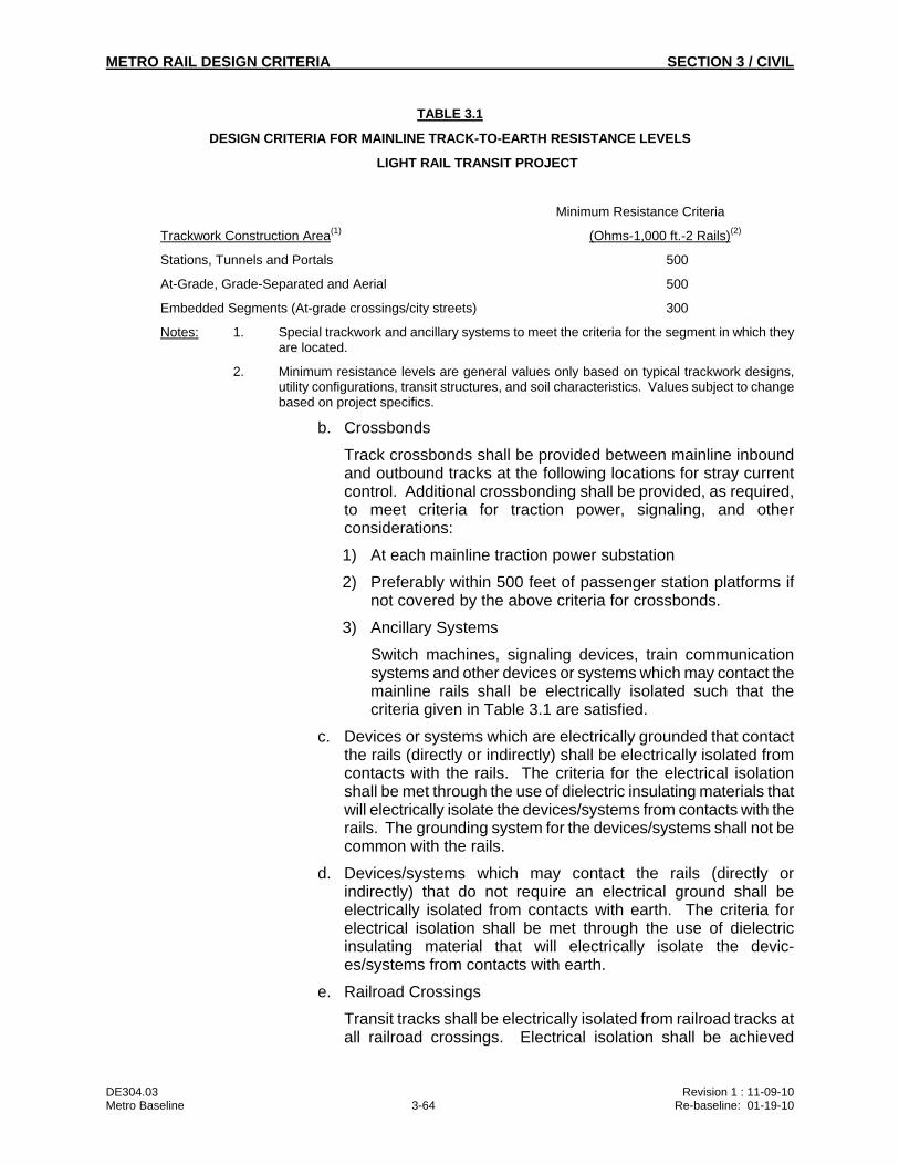
METRO RAIL DESIGN CRITERIA SECTION 3 / CIVIL
DE304.03 Revision 1 : 11-09-10 Metro Baseline 3-64 Re-baseline: 01-19-10
TABLE 3.1
DESIGN CRITERIA FOR MAINLINE TRACK-TO-EARTH RESISTANCE LEVELS
LIGHT RAIL TRANSIT PROJECT
Minimum Resistance Criteria
Trackwork Construction Area(1) (Ohms-1,000 ft.-2 Rails)(2)
Stations, Tunnels and Portals 500
At-Grade, Grade-Separated and Aerial 500
Embedded Segments (At-grade crossings/city streets) 300
Notes: 1. Special trackwork and ancillary systems to meet the criteria for the segment in which they are located.
2. Minimum resistance levels are general values only based on typical trackwork designs, utility configurations, transit structures, and soil characteristics. Values subject to change based on project specifics.
b. Crossbonds
Track crossbonds shall be provided between mainline inbound and outbound tracks at the following locations for stray current control. Additional crossbonding shall be provided, as required, to meet criteria for traction power, signaling, and other considerations:
1) At each mainline traction power substation
2) Preferably within 500 feet of passenger station platforms if not covered by the above criteria for crossbonds.
3) Ancillary Systems
Switch machines, signaling devices, train communication systems and other devices or systems which may contact the mainline rails shall be electrically isolated such that the criteria given in Table 3.1 are satisfied.
c. Devices or systems which are electrically grounded that contact the rails (directly or indirectly) shall be electrically isolated from contacts with the rails. The criteria for the electrical isolation shall be met through the use of dielectric insulating materials that will electrically isolate the devices/systems from contacts with the rails. The grounding system for the devices/systems shall not be common with the rails.
d. Devices/systems which may contact the rails (directly or indirectly) that do not require an electrical ground shall be electrically isolated from contacts with earth. The criteria for electrical isolation shall be met through the use of dielectric insulating material that will electrically isolate the devic-es/systems from contacts with earth.
e. Railroad Crossings
Transit tracks shall be electrically isolated from railroad tracks at all railroad crossings. Electrical isolation shall be achieved
METRO RAIL DESIGN CRITERIA SECTION 3 / CIVIL
DE304.03 Revision 1 : 11-09-10 Metro Baseline 3-65 Re-baseline: 01-19-10
through the use of rail insulating joints with a minimum resistance of 10 megohms. Trackwork within a railroad crossing that is electrically connected to transit trackwork must meet the resistance-to-earth criteria cited in Table 3.1.
f. Electrical Continuity
The running rails shall be constructed as an electrically continuous power distribution circuit through use of rail joint bonds, continuously welded rail or a combination of the two.
5. Storage and Maintenance Yards
Yard traction power shall be provided by a separate dedicated DC power supply electrically segregated in both the positive and negative circuits from the shop and mainline. The yard/mainline traction power segregation points shall be located such that all track on the mainline side of each segregation point is electrically insulated from earth and satisfies the criteria in Table 3.1. The relative positions for the positive and negative yard/mainline insulators shall be such that they satisfy the design requirements for Vehicle Considerations, for minimizing stray current flow through vehicles.
Operating procedures shall preclude the stopping or parking of trains across the positive and negative insulators. The insulators on the positive system shall be of the non-bridgeable type. The yard traction power substation shall be provided with access to the negative bus for stray current monitoring and possible stray current drainage. Access shall be provided either inside through use of dedicated wall space, or outside through use of a weather-tight enclosure with an open conduit between the enclosure and the negative bus. Access to the dedicated wall space or outside enclosure shall be provided through one or more conduits terminated at a manhole(s) located outside the perimeter of the substation near existing underground pipeline that may require stray current corrosion mitigation.
The yard traction power substation shall include provisions for emergency interconnection to the mainline traction power system. If the yard and mainline power originates in the same substation and a positive tie breaker is provided for emergency interconnection of the rectifiers, an interlocked isolating switch is to be provided in the connection between the rectifier negatives.
Yard track including at-grade crossings shall generally not require insulating track fastening devices. Yard track shall be constructed with no direct or indirect electrical connections between the rail and electrically grounded systems. The design of yard track shall include the following minimum provisions:
a. Switch machines, signaling devices, automatic train controls and other devices or systems which are electrically grounded and may contact the rails (directly or indirectly) shall be electrically isolated from contact with the rails. The criteria for electrical isolation shall be met through the use of dielectric insulating materials that will electrically isolate the devices/systems from
METRO RAIL DESIGN CRITERIA SECTION 3 / CIVIL
DE304.03 Revision 1 : 11-09-10 Metro Baseline 3-66 Re-baseline: 01-19-10
contacts with the rails. The grounding system for the devices/systems shall not be common with the rails.
b. Use of a hard rock, nonporous, well-drained high-resistivity ballast material.
c. A minimum of 1-inch clearance between the ballast material and all metallic surfaces of the rail and other metallic track components in electrical contact with the rail.
d. All dead-ended track shall have the negative power rail crossbonded to other negative power rails within 10 feet of the end of the track.
e. All dead-ended tracks shall have insulated joints installed to isolate bumping posts or similar devices that are electrically grounded. Insulated joints shall be located so that a vehicle will not bridge the insulators.
f. Crossbonding negative feeder cables shall utilize a main cable run (possibly several cables) with taps to negative power rail(s) as opposed to long runs of individual cables connected to single negative power rails.
g. Yard track shall be electrically insulated from the shop and mainline tracks by the use of rail insulating joints. Location of the insulating joints shall be chosen to avoid a vehicle bridging the insulator for a time period longer than that required to move a vehicle into or out of the shop.
h. Yard track shall be electrically insulated from railroad track.
6. Maintenance Shop
Shop traction power shall be provided by a separate dedicated DC power supply electrically segregated in both the positive and negative circuits from the yard traction power system and the mainline system. The shop traction power system shall provide power for the following:
a. Shop tracks
b. Car wash tracks
c. Blowdown pit tracks
d. Other tracks associated with maintenance facilities
e. Interconnecting switching tracks between the above listed facilities.
As required for safety purposes, tracks powered by the shop traction power system shall be electrically grounded to the building and building grounding system in which they are located. The design of electrical grounds for track shall include provisions that will preclude unsafe conditions for system personnel during normal and possible fault operations of the shop traction power system.
METRO RAIL DESIGN CRITERIA SECTION 3 / CIVIL
DE304.03 Revision 1 : 11-09-10 Metro Baseline 3-67 Re-baseline: 01-19-10
Track powered by the shop traction power system shall be electrically insulated from yard track by the use of rail insulating joints. Actual locations of insulators shall ensure that vehicles will not electrically connect the track powered by the shop traction power system to the yard track for periods of time longer than that required to move a vehicle into or out of a maintenance building or across an insulating joint.
7. Water Drainage
Subway or below grade sections shall be designed to prevent water from dropping or running onto contact rails, negative rails and rail appurtenances, as well as the accumulation of freestanding water.
Mainline water drainage systems shall be designed to prevent water accumulation from contacting the rails and rail appurtenances.
Yard water drainage systems shall be designed to prevent water accumulating around ties and rail appurtenances.
Shop water drainage systems shall be designed to prevent water accumulation around rail insulating joints when located immediately off the shop apron.
8. Vehicle Considerations
Vehicles shall be designed such that sufficient electrical continuity is provided between trucks and car body and through couplers to safely accommodate a 100- ampere stray current flow. Stray current flow through the vehicle(s) may occur during the bridging of yard/mainline positive and negative insulators.
Metro rail vehicles pantograph location relative to vehicle trucks shall be designed to meet the following requirements and considerations:
a. Pantograph/truck relative locations shall be coordinated with the location of yard/mainline, and yard/shop positive and negative insulators.
b. Relative positions of the pantograph contact to the OCS and the trucks shall be such that the positive contact and at least one negative contact (i.e., one truck) are on the same traction power circuit (i.e., the same side of positive and negative segregating insulators) at all times during operations. Multiple contacts to different negative (running rail) power circuits are permitted as long as one of the contacts is on the same circuit as the pantograph positive contact.
9. Fixed Facilities
a. Subway and Underground Stations (Direct Fixation Track Construction with Insulated Rail Fasteners)
1) Invert Reinforcement
Reinforcing steel in the inverts of subways, portals, and underground stations shall be made electrically continuous. Minimum requirements shall include the following:
METRO RAIL DESIGN CRITERIA SECTION 3 / CIVIL
DE304.03 Revision 1 : 11-09-10 Metro Baseline 3-68 Re-baseline: 01-19-10
Welding of all longitudinal lap splices in the top layer of first-pour reinforcing steel in inverts.
Welding of all longitudinal top layer members in the first-pour reinforcing steel in inverts to a transverse (collector) bar at each end of the structure, at intervals along the structure not exceeding 500 feet and at each side of electrical (physical) breaks in the longitudinal reinforcing steel, such as at expansion joints. Transverse (collector) bars located on each side of breaks in the longitudinal reinforcing steel shall be interconnected electrically with copper bond cables.
Electrical continuity in top layer invert reinforcing steel shall be maintained across bridging beams located at the interfaces between structures. Top-layer longitudinal steel reinforcement or dowels for bridging beams shall be welded at lap splices and interconnected through welded connections or copper bond cables to adjacent top-layer steel reinforcement in structures located on each side of the bridging beam.
Test facilities shall be installed on first-pour reinforcing steel at each end of the structure and at transverse collector bars located at intervals along the structure not exceeding 1,000 feet. Test facilities shall consist of insulated copper wires, conduits, and enclosures terminated at an accessible location. Test facilities shall also be provided on second-pour reinforcing steel for track-work at locations, if any, where second-pour reinforcing steel is electrically interconnected to first-pour reinforcing steel.
b. Tunnel Liners
Stray current control requirements for tunnel liners will vary depending on the particular material and method of construction and must be determined on an individual basis. Minimum requirements shall include the following:
Test reference electrodes shall be installed through tunnel liner walls at maximum intervals of 1,000 feet and shall be located in the tunnel wall most removed from the adjacent tunnel. This criterion does not apply to exterior walls of passenger stations.
Segmented steel tunnel liners shall have electrical continuity within and between segments installed below the concrete invert.
Electrical test facilities shall be installed, in pairs, on fabricated steel tunnel liners. Minimum requirements shall include the following:
A maximum of three-hundred feet (300') between individual test points within a pair.
A maximum of one-thousand feet (1,000') between test station pairs.
METRO RAIL DESIGN CRITERIA SECTION 3 / CIVIL
DE304.03 Revision 1 : 11-09-10 Metro Baseline 3-69 Re-baseline: 01-19-10
Precast segmented concrete tunnel liners shall have permanent access to a section of steel reinforcing within the segment. This access point shall be located adjacent to the test reference electrodes described above. No special provisions are required for electrical continuity of steel reinforcement within the precast segmented liners.
Cast in place tunnel liners shall have test reference electrodes as described in above. There are no special provisions required for providing electrical continuity in steel reinforcement within the cast in place liner.
Prestressed concrete pipe with a steel cylinder used for tunnel liners shall meet the following minimum requirements:
Electrical continuity bonds across all pipe joints.
A minimum of four evenly spaced longitudinal shorting straps between each layer of prestressing wire with electrical interconnections to bell and spigot rings.
Electrical interconnections between prestressing wire anchors and bell and spigot rings.
Provisions for electrically interconnecting the steel pipe cylinder through bond cables to the invert collector grid at maximum intervals of 500-feet along the tunnel. The bond cable from the steel pipe cylinder and the bond cable from the collector grid at interconnection shall terminate in an accessible enclosure with a removable bus bar.
Test reference electrodes as described above.
10. Aerial Structures (Dedicated Transit Non-Vehicular Use)
a. Bridge-Type Structures Using Columns and Bearings (Direct-Fixation Track Construction with Insulated Rail Fasteners)
This Paragraph applies to aerial structures and bridges for which column and bearing assembly is employed that can be electrically insulated from deck or girder reinforcing steel and will have direct-fixation track construction with insulated rail fasteners. Minimum requirements shall include the following:
Electrical continuity of top layer deck/girder reinforcing steel shall be provided by welding all longitudinal lap splices.
All top layer longitudinal deck/girder reinforcing steel shall be electrically interconnected by welding to transverse collector bars installed at each end of the structure and at each side of breaks in longitudinal reinforcing, such as at expansion joints, hinges and abutments. Transverse collector bars installed on each side of a break shall be electrically interconnected with a minimum of two copper bond cables.
Additional transverse collector bars shall be provided at intermediate locations along the structure to maintain a maximum spacing of 500 feet between collector bars.
METRO RAIL DESIGN CRITERIA SECTION 3 / CIVIL
DE304.03 Revision 1 : 11-09-10 Metro Baseline 3-70 Re-baseline: 01-19-10
A stray current ground electrode system with an insulated bond cable shall be provided at each end of the structure and at intermediate locations to maintain a maximum spacing between ground electrode systems of 1500 feet. Each ground electrode system shall be provided an insulated bond cable that is connected to a transverse collector bar located in the electrically continuous reinforcing steel. The bond cable from the ground electrode system and the bond cable from the transverse collector bar shall terminate in the same test facility used for the terminating test wires from the transverse collector bar. The number, location and earth resistance of the ground electrode system must be determined on an individual structure basis.
Test facilities shall be provided at each end of the structure and at intermediate locations to maintain a maximum spacing of 500 feet between test points. The facilities will house test wires from the collector bars and bond cables from the ground electrode system and collector bar, if present. The interconnection between bond cables from a ground electrode system and bond cables from a collector bar shall be made with removable bus bars or shunts.
Reinforcing steel in deck/girders shall be electrically isolated from columns, abutments and other grounded elements. Isolation can be established through the use of insulating elastomeric bearing pads, dielectric sleeves and washers for anchor bolts, and dielectric coating on selected components.
b. Bridge-Type Structures Using Columns and Bearings (Ballasted Track Construction with Insulated Rail Fasteners)
This Paragraph covers the same type of aerial structures covered under Paragraph 3.10.4.B.10.a above, but with timber-tie or concrete-tie and ballasted type of track construction. In this type of track construction, the rails shall be provided insulating track fastening devices. Minimum requirements shall include the following:
Electrical continuity of top layer deck/girder reinforcing steel, transverse collector bars, copper bond cables and test facilities shall be provided.
A stray current ground electrode system with bond cables and test facilities shall be provided.
A waterproofing, electrically insulating membrane shall be provided over the entire surface of the deck that will be in contact with the ballast. The membrane system shall be multi-ply reinforced sheet material with a minimum volume resistivity of 1010 ohm-centimeter and a minimum thickness of 60 mils. The membrane system shall be provided with a protective board where in contact with ballast materials.
Reinforcing steel in deck/girders shall be electrically isolated from columns, abutments and other grounded elements. Isolation can be established through the use of insulating
METRO RAIL DESIGN CRITERIA SECTION 3 / CIVIL
DE304.03 Revision 1 : 11-09-10 Metro Baseline 3-71 Re-baseline: 01-19-10
elastomeric bearing pads, dielectric sleeves and washers for anchor bolts, and dielectric coatings on selected components.
c. Aerial-Type Structures Using Bents and Pre- or Post-Tensioned Girders (Direct-Fixation Track Construction with Insulated Rail Fasteners)
This Paragraph applies to aerial structures using bent supports with reinforcing steel extending into the deck/girders with direct-fixation track construction and insulated rail fasteners. This type of construction precludes the electrical insulation of deck/girder steel from bent/column steel. Stray current ground electrodes systems are not required for these types of structures. Minimum requirements shall include the following:
Electrical continuity of top layer deck/girder longitudinal reinforcing steel shall be provided by welding all longitudinal lap splices.
All top layer deck/girder longitudinal reinforcing steel shall be electrically interconnected by welding to transverse collector bars installed at bents and on each side of breaks in longitudinal reinforcing, such as at expansion joints, hinges and at abutments (deck side only). Collector bars installed on each side of a break shall be connected with a minimum of two copper bond cables.
Electrical continuity of all column/bent steel shall be provided by welding spiral steel reinforcing to two vertical column reinforcing bars. These welded connections to each of the two vertical bars are to be made at the top and bottom of the spiral. Lap splices are to be fillet welded in each of the two vertical column reinforcing bars for electrical continuity.
Column/bent steel is to be electrically interconnected to deck/girder steel by welding at least two vertical column bars to transverse collector bars installed at bents.
Column/bent steel is to be electrically interconnected to footing steel where column/bent steel penetrates the footing by welding the two electrically continuous vertical column/bent bars to footing reinforcing.
Anchor plates for pre- or post-tensioned cables are to be electrically interconnected to electrically continuous longitudinal reinforcing steel by welding a cable between each anchor plate and the longitudinal reinforcing.
Test facilities are to be provided at each hinge and expansion joint and at every other column/bent, starting with the first column/bent from an abutment. Test facilities at hinges and expansion joints will house bonding cables from adjacent collector bars on each side of the hinge/joint. Facilities at columns/bents will house two wires from vertical column/bent steel and from the collector bar at the top of the bent.
METRO RAIL DESIGN CRITERIA SECTION 3 / CIVIL
DE304.03 Revision 1 : 11-09-10 Metro Baseline 3-72 Re-baseline: 01-19-10
d. Aerial-Type Structures Using Bents and Pre- or Post-Tensioned Girders (Ballast Track Construction with Insulated Rail Fasteners)
This Paragraph covers the same type of aerial structures covered under Paragraph 3.10.4.B.10.c above, but with insulated timber-tie or concrete-tie and ballasted type of track construction. Minimum requirements shall include the following:
Electrical continuity of top layer deck/girder reinforcing steel and test facilities shall be provided.
A waterproofing, electrically insulating membrane is to be provided over the entire surface of the deck that will be in contact with the ballast. The membrane system shall be multi-ply reinforced sheet material with a minimum volume resistivity of 1010 ohm-centimeters and a minimum thickness of 60 mils. The membrane system shall be provided a protective board where in contact with ballast material.
Electrical continuity in column/bent reinforcing steel shall be provided.
Column/bent reinforcing steel shall be electrically inter-connected to deck/girder reinforcing steel and to footing steel.
Anchor plates for pre- or post-tensioned cables shall be electrically interconnected to deck/girder reinforcing steel.
e. Existing Bridge Structures (Ballasted Track Construction with Insulated Rail Fasteners)
This Paragraph applies to existing bridge structures that are retrofitted for insulated timber-tie or concrete-tie and ballasted-type track construction.
Stray current corrosion control measures for existing bridges that are retrofitted with new decks must be determined on an individual structure basis, depending on material and methods of construction.
Stray current corrosion control measures for existing reinforced concrete bridge decks used for ballasted track construction preclude the installation of electrical continuity in existing steel reinforcement. In this type of construction, minimum requirements shall include the following:
A waterproofing, electrically insulating membrane is to be provided over the entire surface of the existing concrete deck that will be in contact with the ballast. The membrane system shall be multi-ply reinforced sheet material with a minimum volume resistivity of 1010 ohm-centimeter and a minimum thickness of 60 mils. The membrane system shall be provided a protective board where in contact with ballast material.
METRO RAIL DESIGN CRITERIA SECTION 3 / CIVIL
DE304.03 Revision 1 : 11-09-10 Metro Baseline 3-73 Re-baseline: 01-19-10
An electrically continuous collector grid, such as steel welded wire mesh, shall be provided between the waterproofing membrane and the ballast. The collector grid shall extend the full width of the trackway.
A stray current ground electrode system with an insulated bond cable shall be provided at each end of the structure and at intermediate locations to maintain a maximum spacing between ground electrodes systems of 1500 feet. Each ground electrode system shall be provided an insulated bond cable that is connected to the electrically continuous collector grid. The bond cable from the ground electrode system and the bond cable from collector grid shall terminate in the same test facility used for terminating test wires from the collector grid. The number, location and earth resistance of the ground electrode system must be determined on an individual structure basis.
Test facilities shall be provided at each end of the structure and at intermediate locations to maintain a maximum spacing of 500 feet between test points. The test facilities shall house test wires from the collector grid and bond cables from the ground electrode system and collector grid, if present. The interconnection between bond cables from the ground electrode system and bond cables from the collector grid shall be made with removable bus bars or shunts.
Stray current corrosion control measures for existing steel bridge decks used for ballasted track construction shall include the following minimum requirements:
A waterproofing, electrically insulating membrane similar to that for existing concrete bridges.
Requirements for a stray current ground electrode system on this type of construction must be determined on an individual structure basis, depending on materials and methods of construction for support columns and abutments.
f. Existing Bridge Structures (Direct-Fixation Track Construction with Insulated Rail Fasteners)
This Paragraph applies to existing bridge structures that are retrofitted for insulated direct-fixation track construction.
Stray current corrosion control measures for existing bridges that are retrofitted with new decks must be determined on an individual structural basis, depending on materials and methods of construction.
Stray current corrosion control measures for existing reinforced concrete bridge decks used for direct-fixation track construction preclude the installation of electrical continuity in existing steel reinforcement. In this type of construction, stray current control will be limited to steel reinforcement for trackwork and include the following minimum requirements:
METRO RAIL DESIGN CRITERIA SECTION 3 / CIVIL
DE304.03 Revision 1 : 11-09-10 Metro Baseline 3-74 Re-baseline: 01-19-10
Top-layer longitudinal steel for trackwork shall be made electrically continuous by fillet welding all lap splices.
All top-layer longitudinal reinforcing steel for trackwork shall be welded to a transverse collector bar at each end of the bridge, at intervals along the bridge not exceeding 500 feet and at each side of electrical (physical) breaks in the longitudinal reinforcing steel. Transverse collector bars located on each side of breaks in the longitudinal reinforcing steel shall be interconnected electrically with copper bond cables.
A stray current ground electrode system with an insulated bond cable shall be provided at each end of the bridge and at intermediate locations to maintain a maximum spacing between ground electrodes systems of 1500 feet. Each ground electrode system shall be provided an insulated bond cable that is connected to the electrically continuous reinforcing steel for trackwork. The bond cable from the ground electrode system and the bond cable from the transverse collector bar shall terminate in the same test facility used for terminating test wires from the transverse collector bar. The number, location and earth resistance of the ground electrode system must be determined on an individual structure basis.
Test facilities shall be provided at each end of the bridge and at intermediate locations to maintain a maximum spacing of 500 feet between test points. The facilities will house test wires from the collector bars and bond cables from the ground electrode system and collector bar, if present. The interconnection between bond cables from a ground electrode system and bond cables from a collector bar shall be made with removable bus bars or shunts. Test facilities shall consist of test wires, bond cables, conduits, and enclosures terminated at an accessible location.
g. Existing Box or U-Shaped Structures (Ballast Track Construction with Insulated Rail Fasteners)
This Paragraph applies to existing box or U-shaped structures with a reinforced concrete invert such as retaining walls along the mainline used for ballasted-type track construction. In this type of track construction, the rails shall be provided insulating track fastening devices. This type of construction precludes the installation of electrical continuity in existing invert reinforcement steel. Minimum requirements shall include the following:
A waterproofing, electrically insulating membrane is to be provided over the entire surface of the existing concrete invert that will be in contact with the ballast. The membrane system shall be multi-ply reinforced sheet material with a minimum volume resistivity of 1010 ohm-centimeter and a minimum
METRO RAIL DESIGN CRITERIA SECTION 3 / CIVIL
DE304.03 Revision 1 : 11-09-10 Metro Baseline 3-75 Re-baseline: 01-19-10
thickness of 60 mils. The membrane system shall be provided a protective board where in contact with ballast material.
The need for an electrically continuous collector grid over the membrane and a stray current ground electrode system must be determined on an individual structure basis.
h. New Box or U-Shaped Structures (Ballast Track Construction with Insulated Rail Fasteners)
This Paragraph applies to new construction for box or U-shaped structures such as portals or retaining walls along the mainline with a cast-in-place concrete invert for timber-tie or concrete-tie and ballasted type track construction. In this type of track construction the rails shall be provided insulating track fastening devices. Reinforcing steel in the invert shall be made electrically continuous. Minimum requirements shall include the following:
Welding of all longitudinal lap splices in the top layer of first-pour reinforcing steel in inverts for electrical continuity.
Welding of all longitudinal top layer members in the first-pour reinforcing steel in inverts to a transverse collector bar at each end of the structure, at intervals along the structure not exceeding 500 feet and at each side of electrical (physical) breaks in the longitudinal reinforcing steel, such as at expansion joints. Transverse (collector) bars located on each side of breaks in the longitudinal reinforcing steel shall be interconnected electrically with copper bond cables.
A waterproofing, electrically insulating membrane shall be provided over the entire surface of the concrete invert that will be in contact with the ballast. The membrane shall be multi-ply reinforced sheet material with a minimum volume resistivity of 1010 ohm-centimeter and a minimum thickness of 60 mils. The membrane system shall be provided a protective board where in contact with ballast material.
Test facilities shall be installed at each end of the structure and at transverse collector bars located at intervals along the structure not exceeding 500 feet. Test facilities shall consist of insulated copper test wires for the transverse collector bars, conduits, and enclosures terminated at an accessible location.
C. OCS Pole Foundation Grounding
All metallic components, inclusive of the pole base-plate, to be partially embedded or to come in contact with concrete surfaces shall be coated with a sacrificial or barrier coating. The sacrificial coating shall be applied to the entire component. The barrier coating shall extend a minimum of six inches into the concrete and a minimum of 1/2 inch above the surface of the concrete.
1. At-Grade OCS Support Poles
METRO RAIL DESIGN CRITERIA SECTION 3 / CIVIL
DE304.03 Revision 1 : 11-09-10 Metro Baseline 3-76 Re-baseline: 01-19-10
Electrical continuity shall be established between catenary support pole and pole foundation reinforcing steel to provide an adequate means for dissipating any leakage current from the contact wire and, where applicable, the messenger wire. The following minimum provisions shall be included in the design:
The outermost layer of vertical reinforcing bars within the concrete foundation shall be fillet welded at all intermediate vertical lap joints and to a reinforcing bar collector ring installed at the top and bottom of the reinforcing bar cage.
A copper bond cable, minimum 4/0 #AWG insulated in size, shall be electrically connected between the base of the catenary support pole and the foundation reinforcing steel by thermite welded or brazed connections. The bond cable shall be routed in such a manner that it will not be susceptible to damage during construction or after installation is complete.
Different electrical continuity requirements, from those described above, may be necessary depending on the actual reinforcing configuration for the support pole foundations.
2. OCS Poles on Aerial Structures
OCS poles located on aerial structures shall generally include one of the following minimum sets of provisions, depending on the type of aerial structure.
Where the aerial structure includes electrically continuous (welded) deck reinforcing steel and stray current ground electrode systems, the support poles on the structure shall be electrically interconnected and connected to the ground electrode systems through cabling as follows:
All OCS poles installed on a particular aerial structure shall be interconnected electrically through common cabling. The common cabling between OCS poles shall be interconnected electrically through additional cabling to the stray current ground electrode systems.
Cabling used to interconnect poles and the stray current ground electrode system shall be minimum 1/0 #AWG insulated in size. Cable(s) shall be routed in conduit and terminated in junction boxes or test cabinets that also house test wires and bond cables from the electrically continuous deck reinforcing steel and bond cables from the stray current ground electrode systems.
Cabling associated with the OCS poles that terminates in a junction box or test cabinet shall be connected directly to the bond cable for the stray current ground electrode system.
Where the aerial structure has electrically continuous (welded) deck reinforcing steel but does not include stray current ground electrode systems, the support poles shall be electrically connected to the electrically continuous (welded) deck reinforcing steel.
METRO RAIL DESIGN CRITERIA SECTION 3 / CIVIL
DE304.03 Revision 1 : 11-09-10 Metro Baseline 3-77 Re-baseline: 01-19-10
A minimum of one 1/0 #AWG insulated bond cable shall be provided from each pole to the electrically continuous (welded) deck reinforcing steel. The cable shall be thermite welded or brazed to the pole and preferably to the nearest transverse collector bar installed in the electrically continuous (welded) deck reinforcing steel for the aerial structure.
Where it is not practical, because of excessive distance or other factors, to electrically connect the bond cable(s) from the OCS pole directly to a transverse collector bar, the bond cable(s) are to be electrically connected to at least three local upper-layer longitudinal bars in the electrically continuous (welded) deck reinforcing steel.
D. Metro Owned Utility Structures
All piping and conduit shall be nonmetallic unless metallic facilities are required for specific engineering purposes. There are no special provisions required if nonmetallic materials are used.
1. Metallic Facilities (Systemwide)
Pressure or nonpressure piping exposed within a structure or embedded in the structure shall not require special provisions.
Pressure piping that penetrates the subway, portal or station walls shall be electrically insulated from the external piping to which it connects and from the structure by insulating type watertight wall sleeves. Electrical insulation of interior piping from external piping shall be made on the inside of the subway, portal or station, by the installation of in-line insulating devices.
All buried pressurized piping external to subway, portal, and station structures shall meet the criteria specified for soil corrosion control.
2. Metallic Facilities (Shop)
Top-layer reinforcing steel for the at-grade shop building slab shall be made into an electrically continuous reinforcing grid through fillet welding of lap splices and the installation of collector bars and bond cables. The electrically continuous reinforcing grid for the top-layer reinforcing steel, structural steel and rails within the shop building shall be electrically connected to a common electrical ground system for the rails. See Paragraph 3.10.4.B, Traction Power System, for requirement that the negative circuit (rails) associated with shop traction power systems be interconnected to electrical grounds.
The need to provide an electrically continuous grid for top-layer reinforcing steel in at-grade slabs for other facilities associated with shop traction power systems shall be considered on an individual basis.
All metallic pressure piping within the shop building or perimeter of the shop steel reinforcing grid shall have the following minimum provisions:
Electrical insulation from interconnecting pressure piping located outside the shop building or perimeter of the reinforcing grid.
METRO RAIL DESIGN CRITERIA SECTION 3 / CIVIL
DE304.03 Revision 1 : 11-09-10 Metro Baseline 3-78 Re-baseline: 01-19-10
Insulating devices shall be locate above-grade, or inside the building in lieu of burying directly.
Electrical insulation from the structure by the use of insulating-type watertight wall/floor sleeves.
Electrical connection to the common grounding network at sufficient locations such that there will be only negligible potential differences between the piping and grounding network during fault or normal operating conditions.
All exposed non-pressure piping and electrical conduits within the shop building shall include electrical connection to the building grounding network in accordance with NFPA 70. The connections shall be made at sufficient locations such that there will be only negligible potential differences between the piping or conduit and the grounding network during fault conditions or normal operations.
3. Metallic Facilities (Yard)
It is extremely important from the standpoint of stray current corrosion control that all buried piping and conduits located within the yard be nonmetallic, unless metallic facilities are required for specific engineering purposes.
All buried pressurized metallic piping shall meet the criteria for soil corrosion control and include the following minimum additional provisions for possible stray current drainage to the yard traction power substation:
Electrical continuity.
Electrical insulation from interconnecting non-transit facilities and, possibly, additional insulation to establish discrete electrical units.
Test/access facilities installed at all insulated connections and at intermediate locations as necessary.
All metallic fencing surrounding the yard perimeter shall be made electrically continuous.
All existing abandoned pipelines which pass through the yard shall be excavated and a minimum of two feet of pipe removed just inside the yard perimeter.
Underground storage tanks and associated piping shall comply with the requirements for soil corrosion control.
Prestressed concrete cylinder pipe shall not be used in the area of the yard and shop facilities.
E. Facilities Owned By Others
1. Replacement/Relocation of Facilities
METRO RAIL DESIGN CRITERIA SECTION 3 / CIVIL
DE304.03 Revision 1 : 11-09-10 Metro Baseline 3-79 Re-baseline: 01-19-10
Corrosion control requirements for buried utilities, installed by the authority/operator as part of transit construction, shall be the responsibility of the individual utility operator.
Relocated or replaced utilities installed as part of the Metro contractual agreement by transit contractors shall include the following minimum provisions, unless otherwise directed by the utility owner to follow his own corrosion control standards. These provisions are directed toward ferrous and reinforced concrete pressure piping; other materials and structures will require individual review.
a. Electrical continuity.
b. Test facilities.
c. Electrical isolation by the installation of in-line insulating joints in piping at each end of relocations or replacements and at each side of trackwork for light rail transit projects.
d. The need for additional measures such as application of a protective coating system and/or the installation of cathodic protection shall be based on the characteristics of the specific structure and the performance record within the environment and the possible exposure to stray currents.
All replaced or relocated facilities adjacent to yard(s) shall be reviewed to determine the need for test facilities and possible stray current corrosion mitigation.
2. Existing Utility Structures
The need for stray-current monitoring facilities shall be determined by the individual utility operators. If utilities require assistance, the following minimum provisions shall be suggested:
Test facilities shall be installed at selected locations for the purpose of evaluating stray earth current effects during startup and revenue operations. Guidelines for locations of test facilities for light rail transit systems shall be as follows:
a. At all utility crossings with the system and on structures which are proximate and parallel to the system right-of-way.
b. At locations on specific utility structures which are proximate to the system traction power substations.
Existing facilities adjacent to yard(s) shall be reviewed to determine the need for test facilities and possible stray current corrosion mitigation. See Paragraph 3.10.4.B.5, Storage and Maintenance Yards for requirements pertaining to stray current monitoring and stray current drainage at yard traction power substation.
3. Caltrans Structures (Joint Vehicular/Transit Use)
METRO RAIL DESIGN CRITERIA SECTION 3 / CIVIL
DE304.03 Revision 1 : 11-09-10 Metro Baseline 3-80 Re-baseline: 01-19-10
Stray-current corrosion control for Caltrans structures, principally elevated highways with transit guideways, shall be addressed by limiting earth current levels at the source. Meeting the criteria established in Table 3.1 will provide the primary stray current control for these facilities. The need for and type of supplemental measures shall be determined by Caltrans, with technical input provided by transit designers. General criteria prepared by Caltrans for these structures are shown in Reference 3.10-1.
F. Testing
Reinforced concrete structure designs for providing electrical continuity in reinforcing steel shall include provisions for field testing to insure compliance with design specifications. Minimum testing shall include:
1. Electrical continuity of test facilities.
2. Electrical continuity of reinforcing steel.
Designs for the installation of trackwork shall include provisions for field testing to insure insulating track fastening devices and in-line track insulators are in compliance with design specifications. Minimum testing shall include:
3. Track-to-earth resistance test.
4. Electrical insulating tests to assure rail insulating joints between mainline track and yard track are effective.
5. Electrical insulating tests to assure rail insulating joints between yard track and shop track are effective.
Baseline stray current testing shall be performed for Metro Rail facilities during pre-revenue operations and/or within 2 months after revenue operations commence. All baseline data shall be included as part of an operations and maintenance manual to be used for periodic monitoring.
3.10.5 Atmospheric Corrosion Control
A. General
This subsection provides criteria for designs that will ensure the necessary function and appearance of transit structures exposed to the environment. Criteria are based on preservation of appearance and reduction of maintenance costs. Systemwide criteria for all areas shall include the following:
1. Materials shall have established performance records for the service intended. Nonmetallics shall be used unless metallics are required for special engineering purposes.
2. Sealants shall be used in crevices to prevent the accumulation of moisture.
3. Barrier-type organic or sacrificial-type coatings shall be used on exposed carbon steel, ductile and cast iron and other metals subject to atmospheric corrosion.
METRO RAIL DESIGN CRITERIA SECTION 3 / CIVIL
DE304.03 Revision 1 : 11-09-10 Metro Baseline 3-81 Re-baseline: 01-19-10
4. Design shall avoid configurations that will entrap moisture. Design to permit drainage and allow washing of pollutant particles. Avoid the use of dissimilar metal combinations where possible. Use dielectric devices between dissimilar metal combinations. When this is not possible, use coatings or sealants.
B. Metals Exposed To Weather
1. Steels and Ferrous Alloys
Carbon steel, ductile and cast iron exposed to the atmosphere except for track and track fasteners shall have a barrier-type organic coating or sacrificial-type coating applied to all external surfaces.
High-strength, low-alloy steels shall be protected similarly to carbon steels except where used as a weathering steel exposed to the outside environment. The design shall incorporate complete drainage of all surfaces, the coating of metal-to-metal contacting surfaces and the sealing of crevices.
Organic-type barrier coatings and sacrificial-type coatings shall be in accordance with Paragraph 3.10.5.E, Coatings.
2. Aluminum Alloys
All aluminum alloys shall receive a sealed, hard-anodized finish to provide the best weather-resistant surface.
3. Copper Alloys
Copper and its alloys can be used where exposed to weather. A barrier-type organic coating shall be utilized only where a natural patina is not desired or where there will be intermittent contact with acid rain or fog.
4. Stainless Steels
Stainless steels used for above-grade service shall meet the following minimum requirements:
Series 200, 300, or chromium-molybdenum ferritic types shall be used for exposed surfaces in unsheltered environments and where appearance is critical or a necessary consideration.
Columbium/titanium stabilized grades, or extra-low carbon grades shall be used when welding is required.
Stainless steel surfaces shall be cleaned and passivated after fabrication.
C. Metals Exposed in Stations, Tunnels and Buildings (Excluding Running Rails and Fasteners)
1. Steels and Ferrous Alloys
There are no special or minimum atmospheric corrosion control criteria for components located in an air-conditioned environment.
a. Where appearance is critical, exposed surfaces of steel and ferrous alloys shall be provided a barrier-type organic coating to mitigate superficial corrosion.
METRO RAIL DESIGN CRITERIA SECTION 3 / CIVIL
DE304.03 Revision 1 : 11-09-10 Metro Baseline 3-82 Re-baseline: 01-19-10
b. Galvanizing and other types of sacrificial coatings shall not require a barrier- type organic top coating unless top coating is required for architectural purposes.
Carbon steels, alloy steels, weathering steels, and cast or ductile irons that are not located in an air conditioned environment and not exposed to seepage waters or moisture shall be coated with a barrier-type organic coating or a sacrificial-type coating.
Carbon steels, alloy steels, weathering steels, and cast or ductile irons exposed to seepage waters or moisture shall be coated with a high-build barrier-type organic coating or sacrificial coating with an organic top coating.
Organic-type barrier coatings and sacrificial-type coatings shall be in accordance with Paragraph 3.10.5.E, Coatings.
2. Stainless Steels Exposed in Structures
Materials shall be in accordance with Paragraph 3.10.5.B.4, Stainless Steels, with the following additional requirements when surfaces will be in contact with seepage waters or moisture:
Type 304, 316, 317, 444, Carpenter 20 or higher grade shall be used. Where stains or discoloration are not acceptable, series 300 shall be used.
Barrier-type organic coatings shall not be used when continuous contact or complete immersion in seepage water is anticipated.
3. Aluminum Alloys
Aluminum alloys exposed to seepage water shall be resistant to acid chloride stress corrosion cracking.
Anodized aluminum exposed to seepage water shall have a barrier coating.
4. Copper Alloys
Barrier-type organic coatings shall be used when exposure to seepage of water is anticipated.
A heat-cured or thermosetting lacquer shall be used when discoloration is not permitted.
Brass alloys with zinc content greater than 15 percent shall not be used in areas where exposure to seepage waters is anticipated.
D. Miscellaneous Hardware (Electrical Equipment)
1. Above Grade (Exposed to Weather)
Exterior surfaces of steel and ferrous components shall be provided a barrier-type organic coating or sacrificial coating for atmospheric corrosion control.
Exposed steel conduits, fittings and hardware shall be provided a hot-dip galvanized-type (zinc) sacrificial coating.
2. Inside Stations, Tunnels and Buildings
METRO RAIL DESIGN CRITERIA SECTION 3 / CIVIL
DE304.03 Revision 1 : 11-09-10 Metro Baseline 3-83 Re-baseline: 01-19-10
a. There are no special or minimum atmospheric corrosion control criteria for electrical equipment when located in an air-conditioned environment.
1) Where appearance is critical, exposed surfaces of steel and ferrous alloys shall be provided a barrier-type organic coating to mitigate superficial corrosion.
2) Galvanizing and other types of sacrificial coatings shall not require a barrier- type organic coating unless top coating is required for architectural purposes.
b. Facilities located in a non-air conditioned environment and not exposed to seepage waters shall include one or more of the following:
1) Conduits and fittings shall be hot-dip galvanized.
2) Components that cannot be hot-dip galvanized shall be provided a barrier-type organic coating.
3) Unsealed cabinets shall be internally heated to prevent condensation.
4) Non-oil-immersed internal metallic components of enclosures shall be coated with a barrier-type organic coating or a sacrificial type coating.
5) Vapor phase inhibitors shall be used on sealed cabinets and enclosures where the seal is maintainable.
6) Electrical metallic tubing (EMT) shall not be used.
c. Facilities located in a non-air-conditioned environment and exposed to seepage waters shall include one or more of the above minimum provisions and the following:
1) Non-metallic or stainless steel enclosures and fasteners shall be used wherever possible.
2) Exposed steel conduits and fittings shall be hot-dip galvanized and PVC coated.
3) Exposed galvanized steel surfaces shall be coated with a barrier-type organic coating.
4) Exterior surfaces of components that are not hot-dip galvanized shall be coated with a heavy-build barrier-type organic coating.
5) Electrical metallic tubing (EMT) shall not be used.
E. Coatings
1. General
The term "coating" as used in this subsection means coating system materials, including primers, undercoatings, topcoats, paints and other applied materials such as sacrificial coatings whether used as prime, intermediate, or finish coats for corrosion protection or architectural purposes.
METRO RAIL DESIGN CRITERIA SECTION 3 / CIVIL
DE304.03 Revision 1 : 11-09-10 Metro Baseline 3-84 Re-baseline: 01-19-10
Coatings shall have established performance records for the intended corrosion control or architectural service and be compatible with the base metal to which they are applied.
Coatings shall demonstrate satisfactory gloss retention, color retention and resistance to chalking over their minimum life expectancies.
Coatings shall have minimum life expectancies, defined as the time prior to major maintenance or reapplication, of 15 to 20 years.
The performance and life expectancies of organic coatings depends to a great extent on materials and methods of application and on the environment in which they are to be used. Basic requirements shall include the following:
a. Coatings exposed to weather, water seepage and corrosive environments shall be industrial/maintenance-type products manufactured by companies that are regularly engaged in the manufacturing of such products.
b. Coatings that are not exposed to weather, water seepage and corrosive environments such as those required in stations or buildings shall be architectural or industrial/maintenance-type products manufactured by companies that are regularly engaged in the manufacturing of such products.
c. Coating specifications shall include specific requirements for the preparation and cleaning of surfaces on which organic coatings are to be applied. In general, these requirements shall be in accordance with the coating manufacturer's instructions and referenced to the Steel Structures Painting Council (SSPC).
d. Coating specifications shall include specific requirements for the following:
1) Surface preparation methods.
2) Method of application
3) Number of coats and scheduling between coats.
4) Dry film thickness.
5) Repair of damaged coatings.
6) Inspection of coatings.
e. Ferrous surfaces to be coated are to receive a minimum three-coat system as follows:
1st Coat - Primer
2nd Coat - Intermediate Coat
3rd Coat - Top Coat
f. Galvanized surfaces to be coated are to receive a pretreatment and minimum three-coat system as follows:
Pretreatment - Wash Primer
METRO RAIL DESIGN CRITERIA SECTION 3 / CIVIL
DE304.03 Revision 1 : 11-09-10 Metro Baseline 3-85 Re-baseline: 01-19-10
1st Coat - Primer
2nd Coat - Intermediate Coat
3rd Coat - Top Coat
g. Where complete coating systems are applied after erection, provide primer, intermediate coat and top coat of the same manufacturer.
h. Shop priming is required for ferrous metals fabricated in the shop. Primers shall be compatible with field applied coatings.
i. Products of the same manufacturer shall be used for succeeding coats, including shop-primed materials that are to be finish coated after erection.
j. Shop priming is required for galvanized steel requiring field coating. Galvanized surfaces shall be pretreated prior to priming.
k. Where possible, hot-dipping of galvanizing is required after fabrication of components.
3. Metallic-Sacrificial Coatings
a. Acceptable sacrificial coatings for carbon and alloy steels for use in stations, tunnels, buildings or above grade where surfaces will not be in contact with seepage waters or moisture are as follows:
1) Zinc (hot dip galvanizing or flame sprayed)
2) Aluminum (hot dip or flame sprayed)
3) Aluminum - zinc (hot dip or flame sprayed)
4) Cadmium and electroplated zinc
5) Inorganic zinc (as a primer for vinyl, epoxy, chlorinated rubber and other compatible coatings).
The use of any of the above will depend on the particular application and/or architectural requirements. Hop-dip galvanizing (zinc) after fabrication should be used when there is a choice between the various sacrificial coatings listed.
b. Sacrificial coatings that will be exposed to seepage waters or moisture shall be provided a barrier-type organic top coat such as vinyl or epoxy.
c. The use of cadmium and electroplated zinc shall be limited to dry locations unless provided a barrier-type organic coating.
3. Organic Barrier Coatings
Organic coating systems shall consist of a wash primer (for galvanized and aluminum substrates), a primer, intermediate coat(s) and a finish coat. Acceptable organic coatings for exposure to the atmosphere or moist environments are as follows:
Aliphatic polyurethanes - For interior or exterior metals. To be used as a complete system over primed surfaces or as a top coat over compatible coatings.
METRO RAIL DESIGN CRITERIA SECTION 3 / CIVIL
DE304.03 Revision 1 : 11-09-10 Metro Baseline 3-86 Re-baseline: 01-19-10
Vinyl copolymers - For interior or exterior metals. To be used as a complete system over primed surfaces or as an intermediate or top coat with compatible coatings.
Epoxy - High-build coating for corrosion control of metals in moist and wet environments. To be used as an intermediate coat when exposed to the sunlight or as the complete system when sheltered from sunlight and an architectural top coat is not required.
Chlorinated Rubber - High-build coating for corrosion control of metals in moist and wet environments. To be used as a complete system over primed surfaces.
Fusion-bonded epoxy polyesters, polyethylenes, nylons - For interior or exterior metals. Shop-applied by fluidized or electrostatic spray methods for pre-fabricated ferrous and non-ferrous items.
Acrylics, where not exposed to direct sunlight - Top coat for interior metals and exterior metals in sheltered locations with compatible intermediate coat(s) and primer.
Alkyds, where not exposed to direct sunlight - Top coat for interior metals and exterior metals in sheltered locations with compatible intermediate coat(s) and primer.
Inorganic zinc - Primer for vinyl, epoxy, chlorinated rubber and other compatible coatings.
Wash primers - Pretreatment for galvanizing and non-ferrous metals prior to priming.
4. Conversion Coatings
Conversion coatings such as phosphate and chromate coatings shall be used as pretreatments only for further application of organic coatings.
5. Ceramic - Metallic Coatings
This hybrid-type coating system is acceptable for use on metal panels and fastening hardware when not exposed to moist environments or seepage waters. Barrier-type organic coatings should be used on metal panels with stainless steel fastening hardware in lieu of ceramic coatings when moisture is present.
6. Coatings for Non-Ferrous Metals
Coatings for non-ferrous metals shall consist of compatible primer, intermediate coat(s) and topcoat, supplied by the same manufac-turer. The following provisions shall be included with all coatings:
Wash primers shall be used on copper and copper alloys, and magnesium alloys.
Topcoats shall consist of epoxy, where appearance is not critical, or with an additional topcoat of polyurethane for appearance.
Fusion-bonded epoxy, polyester, polyethylene, or nylon shall be applied by fluidized bed or electrostatic spray methods.
METRO RAIL DESIGN CRITERIA SECTION 3 / CIVIL
DE304.03 Revision 1 : 11-09-10 Metro Baseline 3-87 Re-baseline: 01-19-10
F. Design Requirements
The following minimum provisions shall be included with the design of all facilities:
1. Crevices at joints and fasteners shall be avoided; otherwise a sealant shall be used.
2. Bimetallic couples shall be avoided, through design modification or use of a dielectric material between dissimilar metals.
Acceptable bimetallic couples, subject to review, are as follows:
Aluminum/stainless steel
Stainless steel/carbon steel
Aluminum/zinc (galvanizing)
The following bimetallic couples shall be avoided through design modification or use of dielectric separators:
3. Aluminum/copper (except tinned metals used for electrical connections)
4. Copper/steel
Pump columns used for drainage water ejection systems shall have a barrier-type coal-tar epoxy coating applied to all exterior submerged surfaces.
Contacts between aluminum and concrete or caustic materials shall be avoided, through design modification or use of dielectric materials or barrier-type organic coatings at interfaces.
G. Transit Vehicles
These criteria are directed towards reducing vehicle maintenance and enhancing vehicle appearance by reducing corrosion.
1. Outer shell stainless steels shall be series 200 or 300.
2. Anodized aluminum and stainless steel structural components not exposed to the weather or seepage waters do not require coating or other minimal corrosion control criteria. Stainless steel members shall be Type 304, 316 or equivalent grade. Aluminum shall be 5000 or 6000 series and anodized. Reduced fatigue strength of aluminum caused by anodizing shall be given consideration during design.
3. Carbon steel underframe components shall be coated with an inorganic zinc primer and an epoxy topcoat or flame sprayed aluminum with an epoxy topcoat.
Aluminum underframe components shall be anodized and coated with an epoxy primer and a topcoat.
4. Riveted fastening joints shall have drilled holes and elastic panels seals to prevent fretting. Fasteners shall be aluminum or stainless steel as follows:
Materials to be Joined Fastener Material Required
METRO RAIL DESIGN CRITERIA SECTION 3 / CIVIL
DE304.03 Revision 1 : 11-09-10 Metro Baseline 3-88 Re-baseline: 01-19-10
Aluminum to aluminum Aluminum or series 300 stainless steel
300 series stainless to 300 series stainless 300 series stainless steel
Aluminum to 300 series stainless steel 300 series stainless steel
METRO RAIL DESIGN CRITERIA SECTION 3 / CIVIL
DE304.03 Revision 1 : 11-09-10 Metro Baseline 3-89 Re-baseline: 01-19-10
REFERENCES FOR SECTION 3.10
DESIGN CRITERIA FOR CALTRANS STRUCTURES
PREPARED BY CALTRANS
A. All vertical reinforcing bars in the columns and abutments shall be bonded to a #4AWG test wire in a flush mounted junction box 3 feet above grade at the bottom of each bent and abutment, to periodically monitor stray current activity.
B. A vertical reinforcing bar in each column shall be welded to a nonstructural horizontal #9 bar (collector bar) at each bent cap to ensure a permanent electrical connection from the columns to superstructure. The bent cap bar (collector bar) shall be welded to the longitudinal bars in the deck as described in Item C.
C. All longitudinal reinforcing bars in the top layer of the deck reinforcing mat, including bars under the girder stirrup hooks, shall have all lap splices "tack" welded together to ensure electrical continuity. Transverse collector bars (as described in Item B) shall be provided the full width of the bridge at each bent and at intermediate points, if necessary, so that collector bar spacing does not exceed 200 feet. The transverse collector reinforcing bar shall be the full width of the bridge and "tack" welded at all intersections with the longitudinal top mat deck reinforcing bars. The collector bar shall be #4 or #5 reinforcing bar.
D. The girders between superstructure frames shall be bonded across the hinge with a total of two #2/0 AWG bond wires. The bond wires shall be placed to cross the hinge at the 1/3 points of the bridge width.
E. Two #2/0 AWG wires are to be furnished in a manner similar to that described in Item D, at abutments and tied into junction boxes as indicated in Item A.
F. Electrical continuity in all prestress girder tendons shall be provided by interconnecting the anchor plates at each girder by welding a #6 AWG steel wire. The #6 AWG wire would be weld connected to a transverse #9 collector reinforcing bar as described in Item C.
G. Prestressing steel shall be enclosed within rigid metal galvanize-coated ducts.
H. The rail direct-fixation system shall be insulated from the bridge deck with elastomeric- type pads.
I. Rail direct-fixation anchor bolts shall be insulated into the deck with epoxy (i.e., epoxy grout into drilled holes).
J. Insulating coating shall be provided on column surfaces below ground near tracks (e.g., at freeway level at overcrossings).
REFERENCES FOR SECTION 3.10
1. "Guidelines for Design of Rapid Transit Facilities", Report by American Public Transit Association (APTA), 1981.
2. "Standard for Fixed Guideway Transit Systems", National Fire Protection Association (NFPA), NFPA 130, 2010 Edition.
METRO RAIL DESIGN CRITERIA SECTION 3 / CIVIL
DE304.03 Revision 1 : 11-09-10 Metro Baseline 3-90 Re-baseline: 01-19-10
Figures for Section 3 / Civil
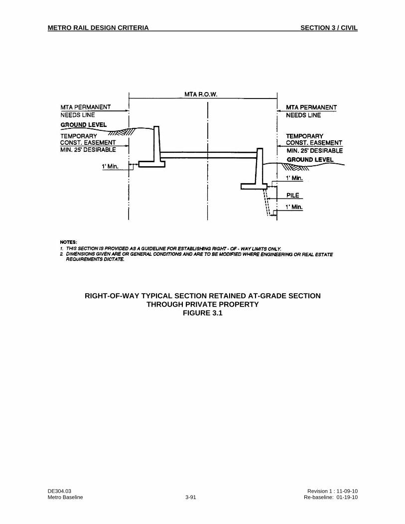
METRO RAIL DESIGN CRITERIA SECTION 3 / CIVIL
DE304.03 Revision 1 : 11-09-10 Metro Baseline 3-91 Re-baseline: 01-19-10
RIGHT-OF-WAY TYPICAL SECTION RETAINED AT-GRADE SECTION THROUGH PRIVATE PROPERTY
FIGURE 3.1
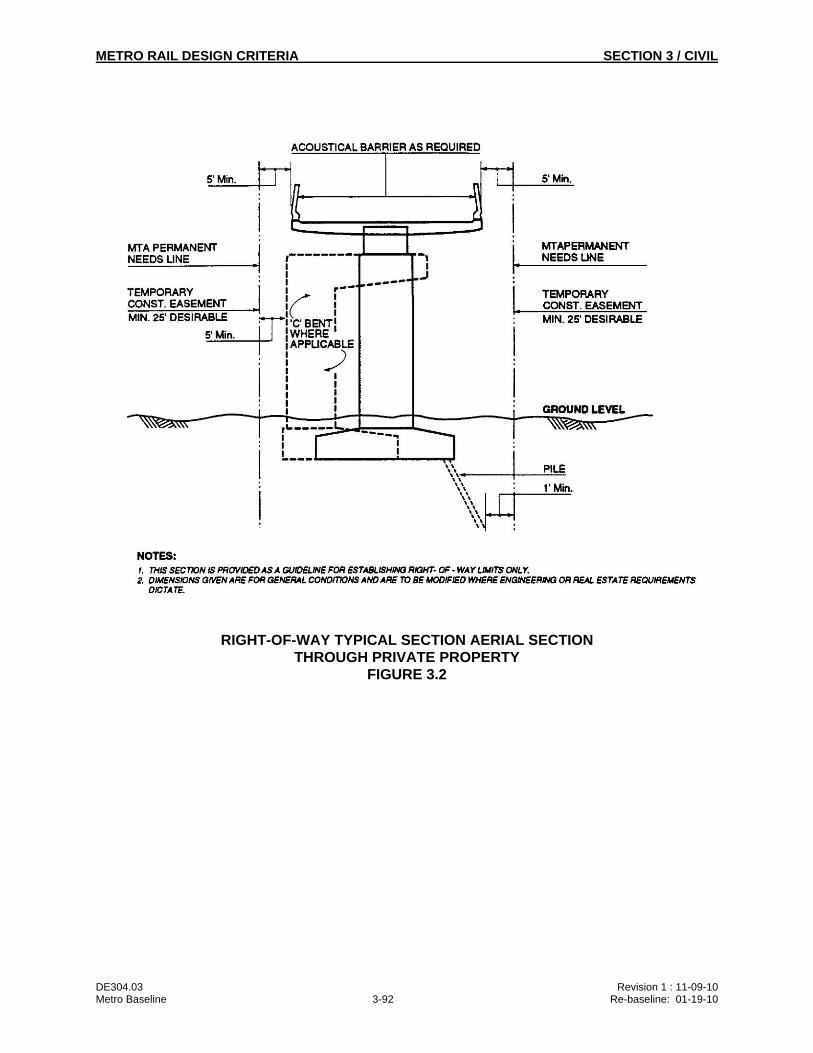
METRO RAIL DESIGN CRITERIA SECTION 3 / CIVIL
DE304.03 Revision 1 : 11-09-10 Metro Baseline 3-92 Re-baseline: 01-19-10
RIGHT-OF-WAY TYPICAL SECTION AERIAL SECTION THROUGH PRIVATE PROPERTY
FIGURE 3.2
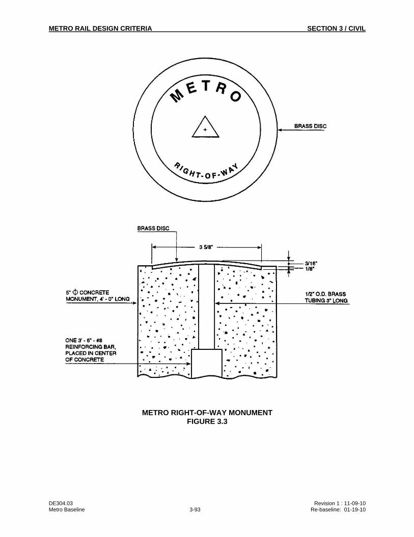
METRO RAIL DESIGN CRITERIA SECTION 3 / CIVIL
DE304.03 Revision 1 : 11-09-10 Metro Baseline 3-93 Re-baseline: 01-19-10
METRO RIGHT-OF-WAY MONUMENT FIGURE 3.3
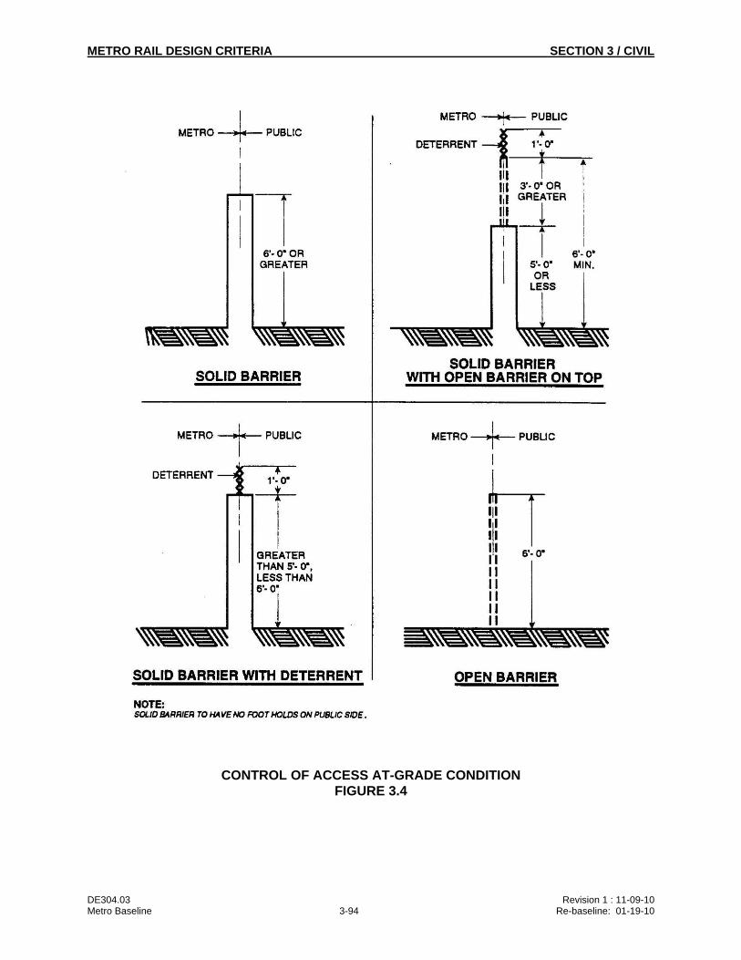
METRO RAIL DESIGN CRITERIA SECTION 3 / CIVIL
DE304.03 Revision 1 : 11-09-10 Metro Baseline 3-94 Re-baseline: 01-19-10
CONTROL OF ACCESS AT-GRADE CONDITION FIGURE 3.4
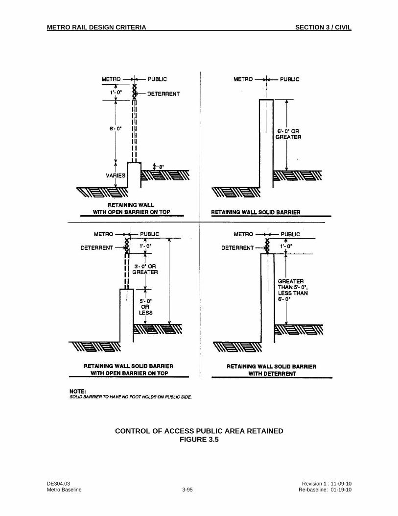
METRO RAIL DESIGN CRITERIA SECTION 3 / CIVIL
DE304.03 Revision 1 : 11-09-10 Metro Baseline 3-95 Re-baseline: 01-19-10
CONTROL OF ACCESS PUBLIC AREA RETAINED FIGURE 3.5
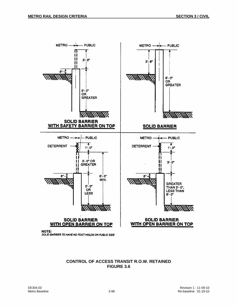
METRO RAIL DESIGN CRITERIA SECTION 3 / CIVIL
DE304.03 Revision 1 : 11-09-10 Metro Baseline 3-96 Re-baseline: 01-19-10
CONTROL OF ACCESS TRANSIT R.O.W. RETAINED FIGURE 3.6
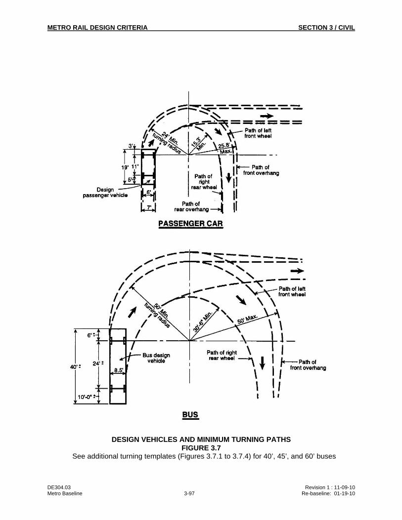
METRO RAIL DESIGN CRITERIA SECTION 3 / CIVIL
DE304.03 Revision 1 : 11-09-10 Metro Baseline 3-97 Re-baseline: 01-19-10
DESIGN VEHICLES AND MINIMUM TURNING PATHS FIGURE 3.7
See additional turning templates (Figures 3.7.1 to 3.7.4) for 40’, 45’, and 60’ buses
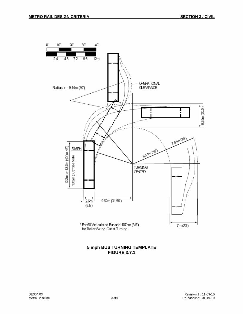
METRO RAIL DESIGN CRITERIA SECTION 3 / CIVIL
DE304.03 Revision 1 : 11-09-10 Metro Baseline 3-98 Re-baseline: 01-19-10
5 mph BUS TURNING TEMPLATE FIGURE 3.7.1
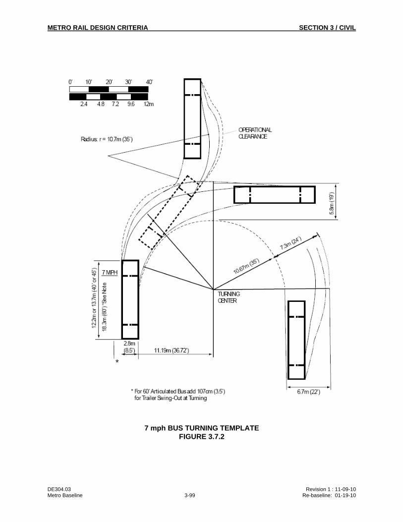
METRO RAIL DESIGN CRITERIA SECTION 3 / CIVIL
DE304.03 Revision 1 : 11-09-10 Metro Baseline 3-99 Re-baseline: 01-19-10
7 mph BUS TURNING TEMPLATE FIGURE 3.7.2
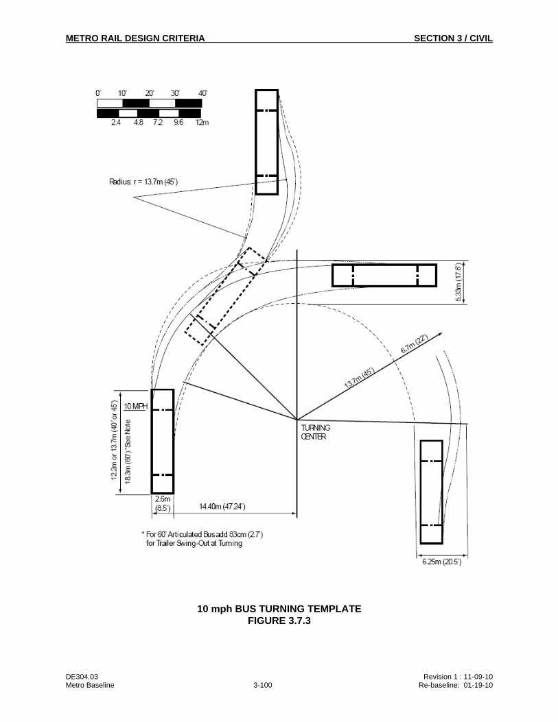
METRO RAIL DESIGN CRITERIA SECTION 3 / CIVIL
DE304.03 Revision 1 : 11-09-10 Metro Baseline 3-100 Re-baseline: 01-19-10
10 mph BUS TURNING TEMPLATE FIGURE 3.7.3
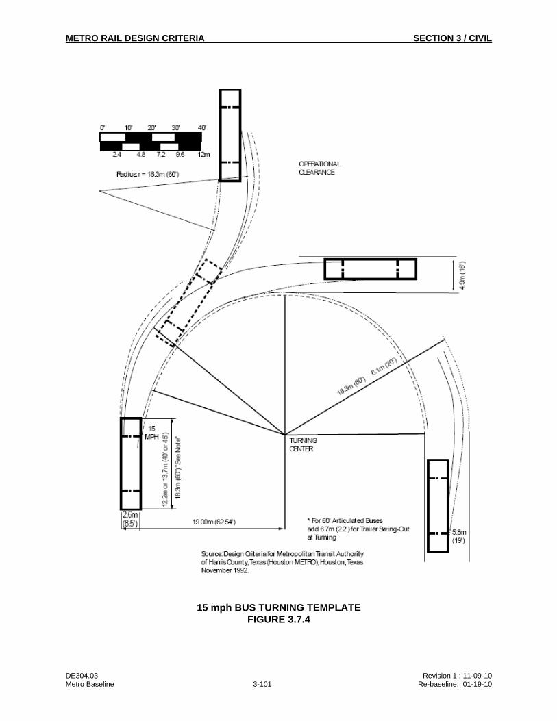
METRO RAIL DESIGN CRITERIA SECTION 3 / CIVIL
DE304.03 Revision 1 : 11-09-10 Metro Baseline 3-101 Re-baseline: 01-19-10
15 mph BUS TURNING TEMPLATE FIGURE 3.7.4
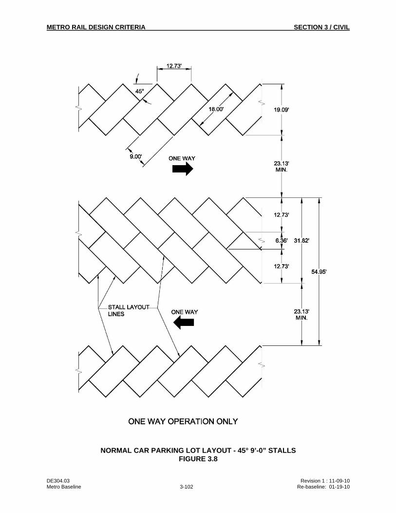
METRO RAIL DESIGN CRITERIA SECTION 3 / CIVIL
DE304.03 Revision 1 : 11-09-10 Metro Baseline 3-102 Re-baseline: 01-19-10
NORMAL CAR PARKING LOT LAYOUT - 45° 9’-0” STALLS FIGURE 3.8
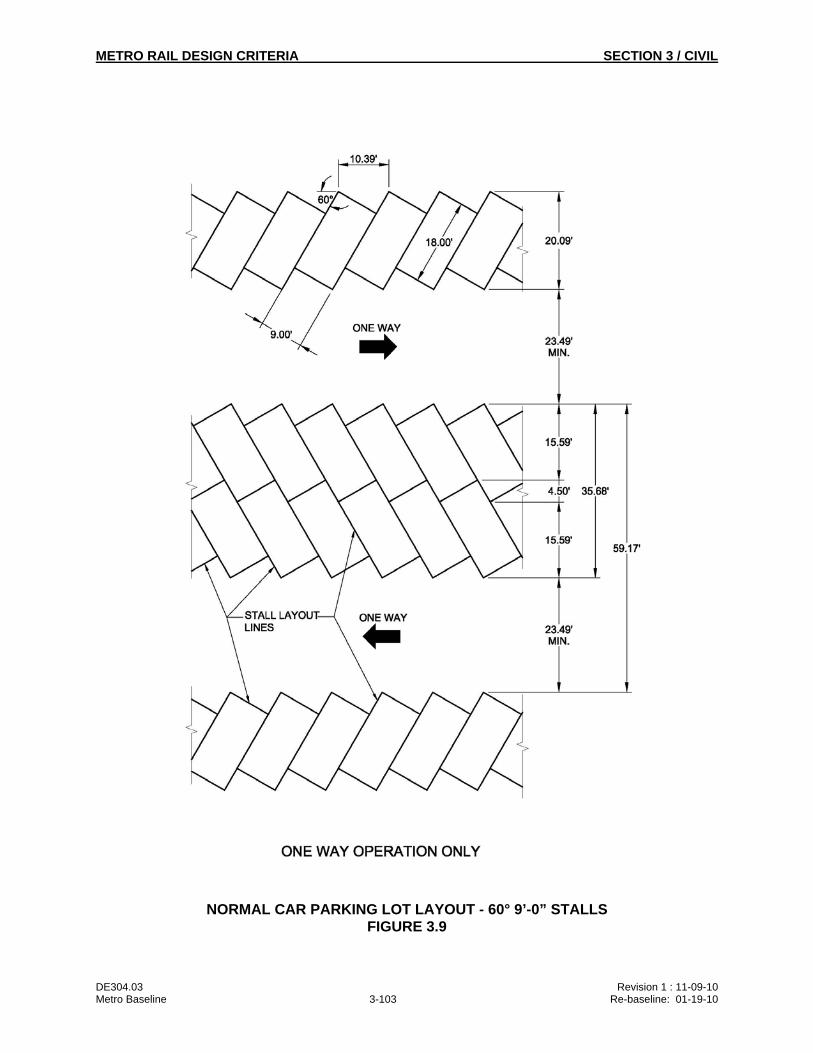
METRO RAIL DESIGN CRITERIA SECTION 3 / CIVIL
DE304.03 Revision 1 : 11-09-10 Metro Baseline 3-103 Re-baseline: 01-19-10
NORMAL CAR PARKING LOT LAYOUT - 60° 9’-0” STALLS FIGURE 3.9
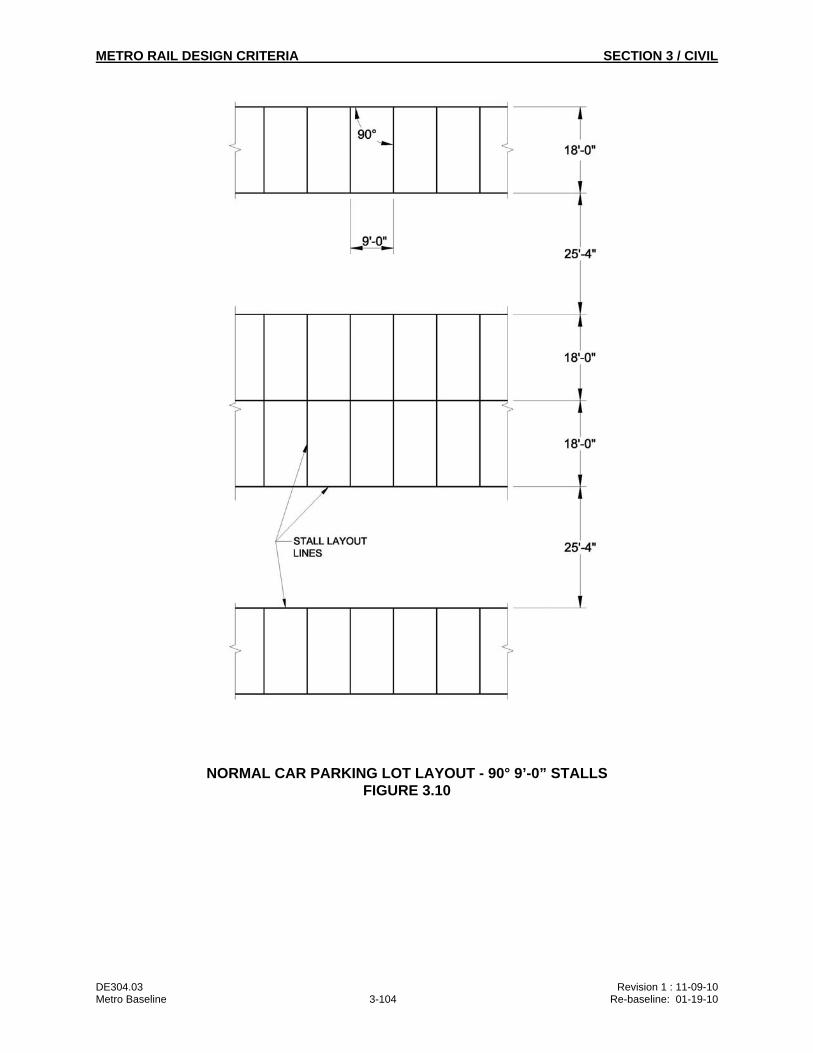
METRO RAIL DESIGN CRITERIA SECTION 3 / CIVIL
DE304.03 Revision 1 : 11-09-10 Metro Baseline 3-104 Re-baseline: 01-19-10
NORMAL CAR PARKING LOT LAYOUT - 90° 9’-0” STALLS FIGURE 3.10
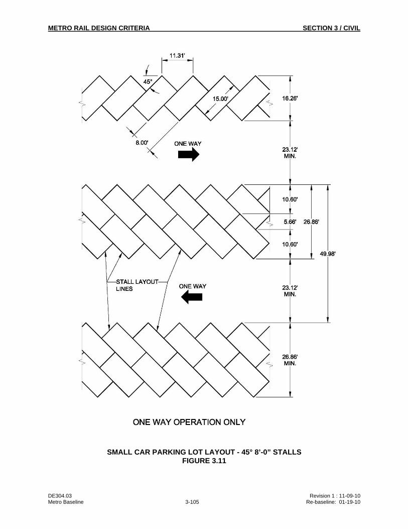
METRO RAIL DESIGN CRITERIA SECTION 3 / CIVIL
DE304.03 Revision 1 : 11-09-10 Metro Baseline 3-105 Re-baseline: 01-19-10
SMALL CAR PARKING LOT LAYOUT - 45° 8’-0” STALLS FIGURE 3.11
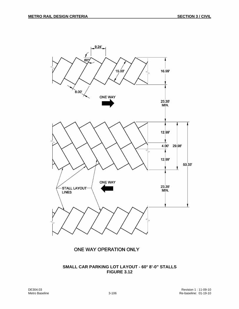
METRO RAIL DESIGN CRITERIA SECTION 3 / CIVIL
DE304.03 Revision 1 : 11-09-10 Metro Baseline 3-106 Re-baseline: 01-19-10
SMALL CAR PARKING LOT LAYOUT - 60° 8’-0” STALLS FIGURE 3.12
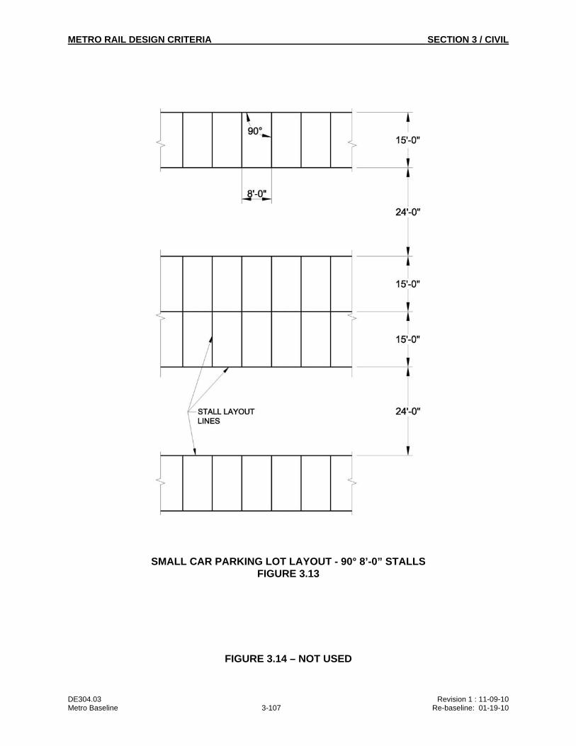
METRO RAIL DESIGN CRITERIA SECTION 3 / CIVIL
DE304.03 Revision 1 : 11-09-10 Metro Baseline 3-107 Re-baseline: 01-19-10
SMALL CAR PARKING LOT LAYOUT - 90° 8’-0” STALLS FIGURE 3.13
FIGURE 3.14 – NOT USED
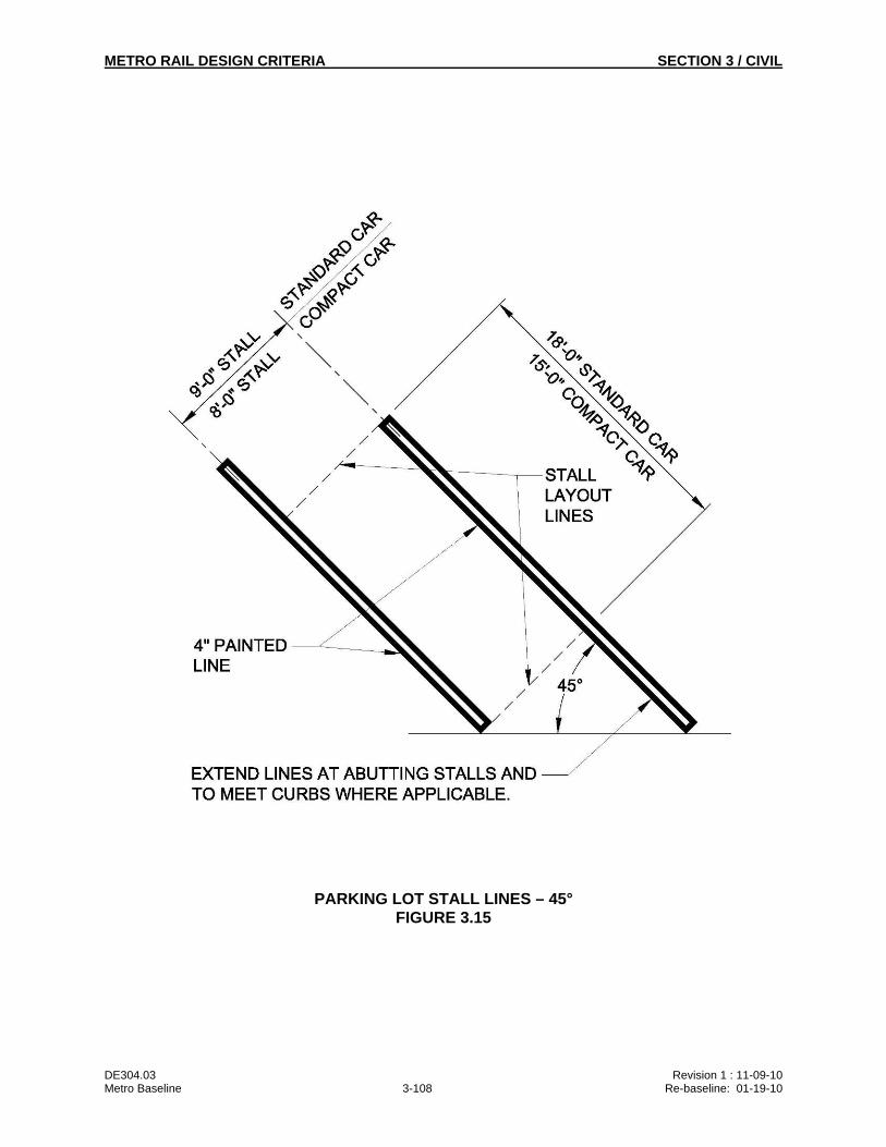
METRO RAIL DESIGN CRITERIA SECTION 3 / CIVIL
DE304.03 Revision 1 : 11-09-10 Metro Baseline 3-108 Re-baseline: 01-19-10
PARKING LOT STALL LINES – 45° FIGURE 3.15
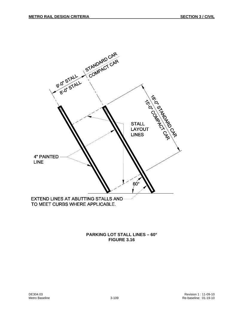
METRO RAIL DESIGN CRITERIA SECTION 3 / CIVIL
DE304.03 Revision 1 : 11-09-10 Metro Baseline 3-109 Re-baseline: 01-19-10
PARKING LOT STALL LINES – 60° FIGURE 3.16
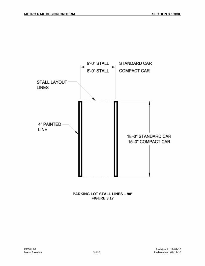
METRO RAIL DESIGN CRITERIA SECTION 3 / CIVIL
DE304.03 Revision 1 : 11-09-10 Metro Baseline 3-110 Re-baseline: 01-19-10
PARKING LOT STALL LINES – 90° FIGURE 3.17
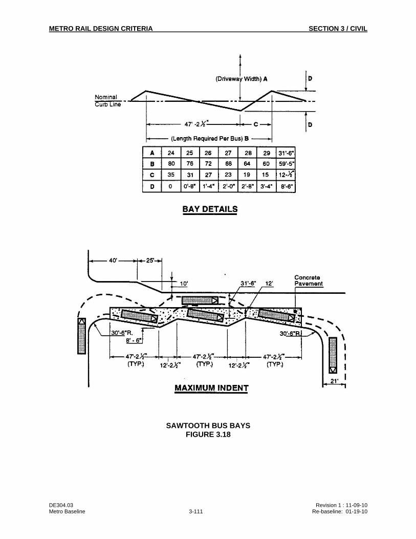
METRO RAIL DESIGN CRITERIA SECTION 3 / CIVIL
DE304.03 Revision 1 : 11-09-10 Metro Baseline 3-111 Re-baseline: 01-19-10
SAWTOOTH BUS BAYS FIGURE 3.18
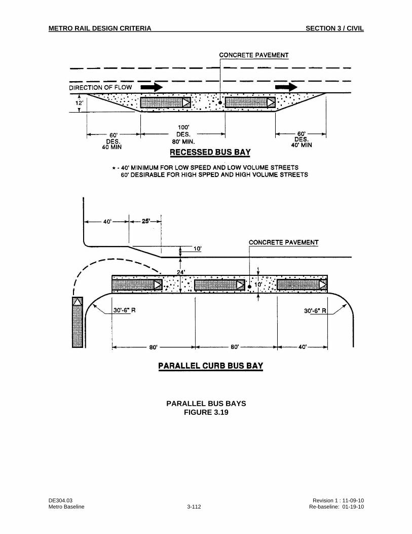
METRO RAIL DESIGN CRITERIA SECTION 3 / CIVIL
DE304.03 Revision 1 : 11-09-10 Metro Baseline 3-112 Re-baseline: 01-19-10
PARALLEL BUS BAYS FIGURE 3.19
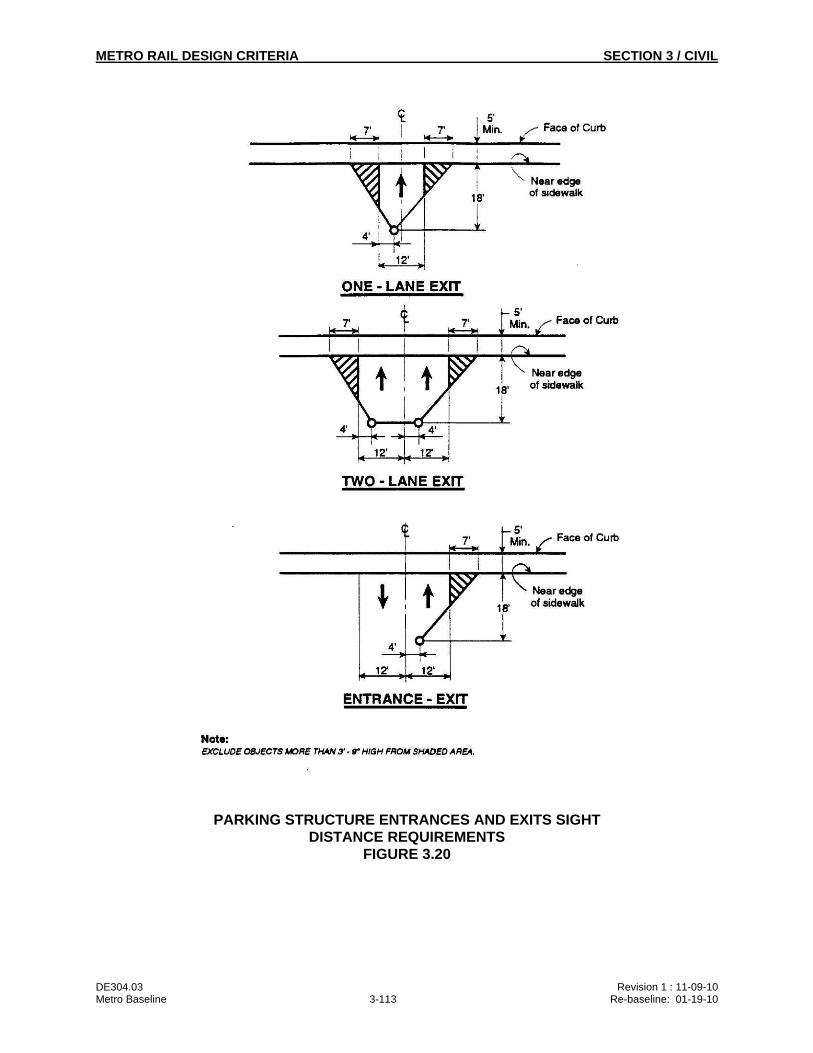
METRO RAIL DESIGN CRITERIA SECTION 3 / CIVIL
DE304.03 Revision 1 : 11-09-10 Metro Baseline 3-113 Re-baseline: 01-19-10
PARKING STRUCTURE ENTRANCES AND EXITS SIGHT DISTANCE REQUIREMENTS
FIGURE 3.20
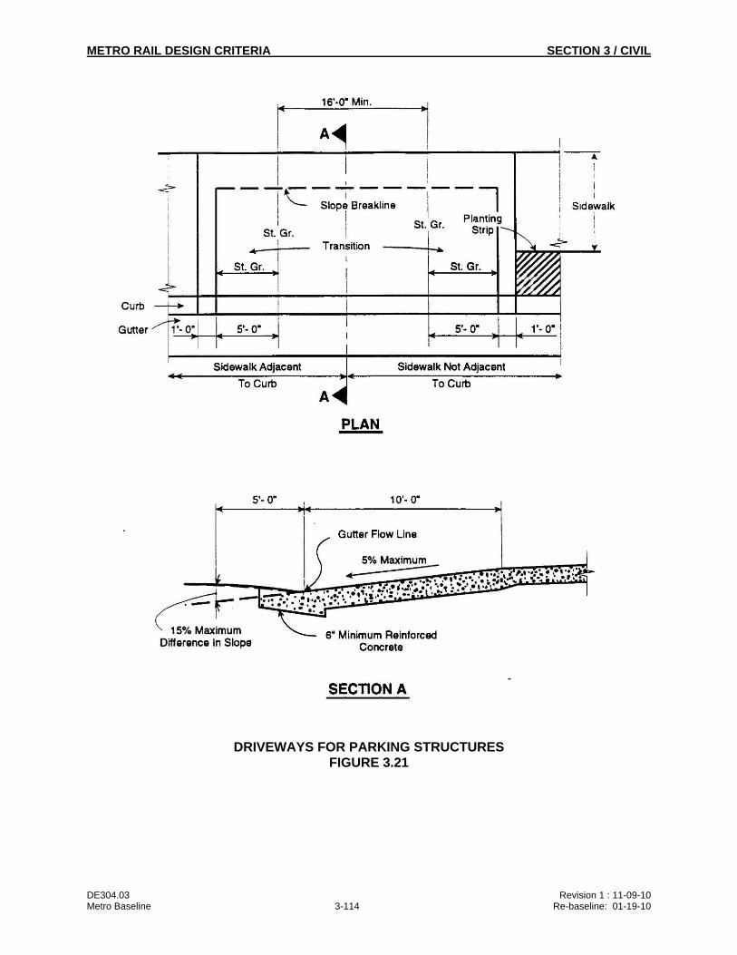
METRO RAIL DESIGN CRITERIA SECTION 3 / CIVIL
DE304.03 Revision 1 : 11-09-10 Metro Baseline 3-114 Re-baseline: 01-19-10
DRIVEWAYS FOR PARKING STRUCTURES FIGURE 3.21