methods for collection and analysis of geopressured ... · pdf filemethods for collection and...
TRANSCRIPT

Methods for Collection and Analysis of Geopressured Geothermal and Oil Field Waters
United States Geological SurveyWater-Supply Paper 2194
Methods for Collection and Analysis of Geopressured Geothermal and Oil Field Waters
By MICHAEL S. LICO, YOUSIF K. KHARAKA,
WILLIAM W. CAROTHERS, and VICTORIA A. WRIGHT
GEOLOGICAL SURVEY WATER-SUPPLY PAPER 2194

UNITED STATES DEPARTMENT OF THE INTERIOR
JAMES G. WATT, Secretary
GEOLOGICAL SURVEY
Dallas L. Peck, Director
UNITED STATES GOVERNMENT PRINTING OFFICE: 198
For sale by the Superintendent of Documents U.S. Government Printing Office Washington, D.C. 2O4O2
Library of Congress Cataloging in Publication Data
Methods for collection and analysis of geopressured geothermal and oil field waters
(Geological Survey water-supply paper; 2194)Bibliography: p. 20.1. Geothermal engineering. 2. Water, Underground.
3. Oil field brines. 4. Water Analysis.I.Lico, Michael S. II. Series.
TJ280.7.M47 621.44 82-600061AACR2
CONTENTS
Abstract 1 Introduction 1 Field procedures 1
Sampling at the wellhead 1Sample filtration and preservation 2Extraction of aluminum 3Sample collection and preparation for stable carbon
isotopes and total dissolved carbonate 4 Chemical analysis 4
Sulfide determination by iodometric method 5Sulfide determination by specific-ion electrode
method 6Alkalinity 7pH 7Ammonia 8Specific conductance 8
Laboratory procedures 8 Sodium 8 Potassium 9 Calcium 9 Magnesium 9 Strontium 10 Iron 10 Manganese 11 Zinc 11 Lead 11 Aluminum 11 Mercury 12 Lithium 12 Rubidium 13 Cesium 13 Barium 13Chloride by titration with silver nitrate 14 Fluoride by ion-specific electrode 14 Bromide and iodide by hypochlorite oxidation method 15 Sulfate by thorin method with alumina pretreatment 17 Boron by carmine method 18 Silica by molybdate blue method 19 Aliphatic acid anions by gas chromatography 19
References 20
FIGURES1. Diagram of gas collecting apparatus 52. Diagram of alumina column and associated apparatus 18
Contents HI
Methods for Collection and Analysis of Geopressured Geothermal and Oil Field Waters
By Michael S. Lico, Yousif K. Kharaka, William W. Carothers, and Victoria A. Wright
Abstract
Present methods are described for the collection, preser vation, and chemical analysis of waters produced from geopres- sured geothermal and petroleum wells. Detailed procedures for collection include precautions and equipment necessary to en sure that the sample is representative of the water produced. Procedures for sample preservation include filtration, acidifica tion, dilution for silica, methyl isobutyl ketone (MIBK) extrac tion of aluminum, addition of potassium permanganate to pre serve mercury, and precipitation of carbonate species as stron tium carbonate for stable carbon isotopes and total dissolved carbonate analysis. Characteristics determined at the well site are sulfide, pH, ammonia, and conductivity.
Laboratory procedures are given for the analysis of lithium,
sodium, potassium, rubidium, cesium, magnesium, calcium, strontium, barium, iron, manganese, zinc, lead, aluminum, -and mercury by atomic absorption and flame emission spectroscopy. Chloride is determined by silver nitrate titration and fluoride by ion-specific electrode. Bromide and iodide concentrations are determined by the hypochlorite oxidation method. Sulfate is analyzed by titration using barium chloride with thorin indicator after pretreatment with alumina. Boron and silica are deter mined colorimetrically by the carmine and molybdate-blue methods, respectively. Aliphatic acid anions (C2 through Cs) are determined by gas chromatography after separation and con centration in a chloroform-butanol mixture.
INTRODUCTION
An intensive research and development effort is presently underway by public agencies and private com panies to determine the feasibility of using geopressured geothermal waters as a source of energy. Huge volumes of water are required for the extraction of heat, hydraulic energy, and dissolved gases from geopressured systems. For example, the volume of water produced from one geopressured geothermal well is expected to range from about 1,600 cubic meters, or 10,000 barrels, to more than 8,000 cubic meters, or 50,000 barrels, per day. Ap proximately 10 wells will be required to supply geother mal fluids at I50°C to each 25-megawatt powerplant (Underhill and others, 1976).
The amount of water produced with oil and gas also will continue to increase. This increase is the result of increasing total amounts of oil and gas being pro duced and, more importantly, petroleum wells that pro duce large volumes of water are now economical to keep in production. Proper management of these larger vol umes of water will require more detailed and accurate data on the chemical composition of the water than the data routinely obtained by petroleum companies.
The authors have been collecting and analyzing geopressured geothermal and oil field waters for 10 years. This report summarizes their latest methods for the col lection, preservation, and detailed analysis of these wa
ters. These methods are, for the most part, based upon, but are significantly different from, those used for surface and shallow ground waters (Skougstad and others, 1979; American Public Health Association, 1971), or those now used for oil-field waters (American Petroleum Institute, 1968; Collins, 1975), or those used for geothermal waters (Presser and Barnes, 1974; Watson, 1978). For the methods of analysis of trace metals not reported here, see Skougstad and others (1979).
FIELD PROCEDURES
Sampling at the Wellhead
Collection of samples should include steps to pre vent contamination and to preserve the samples for later analysis; therefore, it is essential to collect samples as near the wellhead as possible and to isolate them from the atmosphere. Most oil field and geopressured geoth ermal wells have, or can be fitted with, sampling valves at or close to the wellhead. If the sample must be taken from the separator, the separator should be emptied of contained fluids and solids before sampling. The separator is then flushed with new formation water prior to sampling. Samples for trace metals should not be taken at or downline from the separator because of the possibility of precipitation of heavy metal oxyhydroxides
Field Procedures 1

and carbonates in the separator and the possible presence of corrosion products that could contaminate the sample. If corrosion inhibitors are being added to the well, it is necessary to stop adding them at least 1 hour prior to sampling the well.
Wells should be carefully selected to ensure that the samples obtained are representative of the waters present in the producing zone. The wells sampled should (D be perforated over known intervals, (2) be producing from a single zone, (3) not be affected by water flooding, and (4) not contain water diluted by condensed water which is common in gas wells producing less than about 1 cubic meter of water per 30,000 cubic meters of gas, or 6 barrels per million cubic feet (Kharaka and others, 1977).
ApplicationAll formation waters for collection and determina
tion of cations, anions, alkalinity, stable isotopes, pH, and temperature.
ReagentsSAOB II solution (as described in the section on
"Sulfide determination by specific-ion electrode method").
Apparatus1. Carboy, 2- or 5-gallon, with bottom spigot.2. Glass wool.3. Bottles, flint-glass, 125-mL with Poly-Seal 1 caps.4. Thermometer.5. Tubing, polyvinyl chloride, and fittings for well
head connections.6. Flasks, volumetric, 100-mL.
Procedure1. Attach tubing to the wellhead, open valve, and
flush the lines.2. Measure the temperature of water under flow.3. Rinse all collection containers at least twice with
sample water.4. Fill the carboy with water. Minimize contact of
the sample with air by inserting the tubing as far as possible into the carboy through a hole in the cap. Plug the hole in the cap with a rub ber stopper after the carboy is filled.
5. Fill completely and tightly cap four separate flint-glass bottles by passing the water from the tubing through glass wool placed in a funnel to remove any solids and oil droplets. These bot tles will be used for the hydrogen sulfide (iodometric), alkalinity, carbon isotopes, and pH determinations. Label these samples raw unacidified (RU).
6. Collect sample for specific-ion electrode determi nation of sulfide by filling a 100-mL volumetric
Any use of trade names is for descriptive purposes only and does not imply endorsement by the U.S. Geological Survey.
flask containing 50 mL of SAOB II solution (see section on "Sulfide determination method by specific-ion electrode") to the mark with sample.
7. Collection from oil and gas-condensate wells is somewhat different. Fluid is collected in a car boy and the two phases (oil and water) are al lowed to separate. This takes from 5 minutes to several hours, depending on the temperature and the proportion of water produced. When separation occurs, proceed with steps 5 through 6 using water obtained through the spigot at the bottom of the carboy.
Sample Filtration and Preservation
Filtration and preservation of samples immediately after collection is important to prevent loss of con stituents through precipitation and colloidalization. Cat ions such as manganese, calcium, iron, strontium, and barium can form oxyhydroxides and carbonates that may precipitate if the samples are not treated. Filtration through 0.1-/^m filters is required for trace-metal and mercury samples because colloidal metallic hydroxides and clay particles can pass through larger pore sizes (Kennedy and others, 1974). These particles would dis solve upon acidification, thus forming concentrations of trace metals not representative of the waters. Filtration through a 0.45-/^m filter is adequate for determination of anions and other cations.
Polyethylene bottles with airtight caps are used to store the filtered samples. The bottles must be prewashed with 10-percent nitric acid and rinsed with distilled- deionized water. Bottles for trace metals are prewashed with a 10-percent sulfuric-nitric acid mixture, rinsed with distilled-deionized water, and dried under positive-filtered air flow (J.W. Ball, oral commun., 1980). Bottles for mer cury samples are cleaned by soaking in a chromic acid solution for 24 hours, followed by rinsing with distilled- deionized water, and then by heating in an oven at >200°C for 24 hours (Ball and others, 1976).
A filtration unit described by Ball and others (1976) is used to filter the samples. This unit is constructed of two Geofilter plastic disks sealed with a rubber O-ring and supported by polyvinyl legs. All tubing used is Tygon plastic. A peristaltic pump provides pressure for filtration.
NOTE: All chemicals used in the following analyses are American Chemical Society certified reagent- grade chemicals unless otherwise stated.
ApplicationFormation waters relatively free of oils or suspended
matter can be filtered rather easily. Reagents
1. Hydrochloric acid, concentrated.
2 Field Procedures

2. Nitric acid, doubly distilled (J. T. Baker's Ultrex HNOj).
3. Potassium permanganate solution (KMnO 4 ), 5 percent. Dissolve 5 g of KMnO-i in water, di lute to 100 mL
Apparatus1. Filtration pump (Cole Farmer-Masterflex).2. Filtration assembly and holder for 142-mm disk
filter membrane.3. Filter membrane, 0.1-^m and 0.45-//m (142-mm
diam).4. Tubing, Tygon, for connecting pump and filter.5. Bottles, polyethylene, with caps, 1-liter and 125-
mL6. Bottles, flint-glass, with Poly-Seal caps, 125 mL7. Bottles, glass stoppered, 1-liter, for mercury sam
ples. Procedure
1. Attach Tygon tubing to the carboy, filtration pump, and filtration unit.
2. Rinse the filter (0.1-^m) by first passing through at least 1 liter of sample. Discard the first 250 mL of sample; use the remainder to rinse all bottles (rinse twice) prior to filling. Collect a 1-liter sample in a polyethylene bottle for trace-metal analyses.
3. Collect 1 liter of sample filtered through a 0.1-//m filter in a 1-liter glass-stoppered bottle for mer cury analysis. Add potassium permanganate solution until sample remains purple. Record amount of solution added for later volume cor rection.
4. Collect 2 liters of water filtered through a 0.45- //m (or 0.1 -//m) filter in polyethylene bottles for cation and anion analyses. Label one of these as filtered unacidified (FU). Acidify the other bottle with concentrated HC1 to pH ~1.5-2.0; label this sample filtered acidified (FA).
5. Collect sample for stable isotopes (H/D and "O/ I6 O) in a 125-mL flint-glass bottle. Fill bot tle completely with water.
6. Acidify the sample for trace metals with nitric acid to pH 1.5.
7. Make 1:4 and 1:1 dilutions on a filtered, un acidified sample for silica analysis in the laboratory. Store in 125-mL polyethylene bot tles.
Extraction of Aluminum
Extraction of monomeric or reactive aluminum in solution must be done in the field if measured aluminum values are to be used in chemical models that study water-rock reactions (Kharaka and Barnes, 1973).
Aluminum is complexed with 8-hydroxyquinoline and ex tracted in methyl isobutyl ketone (MIBK.) after the sam ple has been filtered through 0.1-//m filter paper (Barnes. 1975). Samples with concentrations of iron greater than about 0.4 mg/L require pretreatment; samples with con centrations of iron greater than 10 mg/L cannot be ex tracted by this method (Barnes, 1975). Application
Formation waters with total aluminum concentra tions greater than 3 yug/L.
Reagents1. Hydrochloric acid, concentrated, metal free.2. Ammonium hydroxide, concentrated, metal free.3. Standards, Aluminum, 0, 12.5, 25, 50 //g/L Al.
Dissolve 0.500 g of Al wire in concentrated HC1, dilute to 500 mL with distilled-deionized water. Dilute this stock (1,000 mg/L Al) to ap propriate concentrations for field standards.
4. Phenol red. Dissolve 0.1 g of phenol red in 28 mL of 0.01 N NaOH and dilute to 250 mL with aluminum-free water.
5. 8-hydroxyquinoline, 5 percent. Dissolve 5 g of 8-hydroxyquinoline in 10 mL of glacial acetic acid and dilute to 100 mL with aluminum-free water.
6. MIBK (methyl isobutyl ketone).7. Hydroxylamine hydrochloride, 20 percent. Dis
solve 20 g of hydroxylamine hydrochloride in water and dilute to 100 mLwith aluminum-free water.
8. 1,10-phenanthroline, 1 percent. Dissolve 1 g of 1,10-phenanthroline in water to which a few drops of concentrated HC1 have been added and dilute to 100 mL with aluminum-free wa ter.
9. Buffer solution. Add 223 mL of 19 M NH 4 OH (metal free) and 115 mL of glacial acetic acid to approximately 500 mL water. Adjust the pH to 8.3 with 10 M NH4OH or glacial acetic acid. Dilute to 1,000 mLwith aluminum-free water.
NOTE: These reagents should be kept refriger ated after preparation.
Apparatus1. Separatory funnels, 500-mL2. Graduated cylinders, 500-mL.3. Ring stand and holder for separatory funnels.4. Vials, 15-mL, with Poly-Seal caps.
Procedures1. Measure 400 mL of sample into the separatory
funnel.2. Add 10 to 15 drops of phenol-red solution and 2
mLof 5 percent 8-hydroxyquinoline and swirl.3. Raise the pH by adding ammonium hydroxide
until solution turns red (pH ~8). If a greenish-black precipitate forms as the pH is
Field Procedures 3

raised (step 3), discard the sample and pretreat a new aliquot of the sample as follows:
a. Measure 400 ml of sample into separa-tory funnel.
b. Add 5 mL of 20 percent hydroxylamine hydrochloride and 5 mL of 1 percent 1,10-phenanthroline.
c. Adjust the pH to about 4 with hyd rochloric acid, swirl, and allow to stand ~30 minutes to reduce iron,
d. Continue with step 2 above. NOTE: If red color of indicator is obscured as
pH is raised in step 3, use a pH meter to monitor the pH.
4. Immediately add 5 mL of buffer solution and 15 mLof MIBK.
5. Shake vigorously 10 to 30 seconds (shaking time and intensity must be uniform for all standards and samples).
6. Allow the two phases to separate.7. Discard the aqueous phase.8. Collect the MIBK extract in vials which are then
tightly sealed and refrigerated.9. Standards as well as samples must be carried
through steps 1 through 8 in the field.
Sample Collection and Preparation for Stable Carbon Isotopes and Total Dissolved Carbonate
PrincipleDissolved carbonate species are precipitated as stron
tium carbonate in evacuated glass cylinders con taining a saturated solution of strontium chloride in ammonium hydroxide (ammoniacal strontium chloride) at the sampling site. The collection method prevents the sample from being exposed to atmospheric contamination. The precipitate is fil tered, washed, dried, and weighed under laboratory conditions. A weighed portion of the sample is reacted with phosphoric acid and evolved carbon dioxide is measured for total dissolved carbonate. The I3C/ 12 C ratio of the carbon dioxide is measured by mass spectrometer.
ApplicationI3 C/ I2 C ratios of total dissolved carbonate species
in formation waters can be determined. Reagents
1. Ammonium hydroxide, concentrated.2. Strontium chloride, crystals.
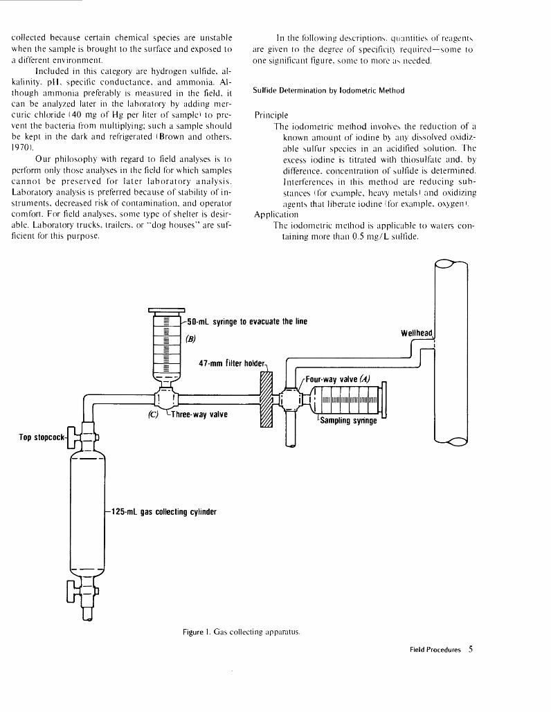
Apparatus (fig. 1)1. Cylinders, 125-mL glass gas-collecting, with stop
cocks at both ends.2. Filter membranes, 0.45-yum, (47 mm diam.).
3. Filter holder, 47 mm.4. Syringes, 50-mL (two).5. Tubing, Tygon.6. Valves, plastic, three- and four-way (one each).7. Connectors, tubing.
Procedures1. Pre-field preparations. The following steps are to
be done in a carbon dioxide-free environment, usually a glove box purged with an inert gas: a. Prepare the ammoniacal strontium chloride
by dissolving strontium chloride in con centrated ammonium hydroxide until supersaturated. Let stand 24 hours,
b. Filter the ammoniacal strontium chloridesolution.
c. Place 15 mL of ammoniacal SrCl: in a 125-mL glass gas-sampling cylinder and evacuate the cylinder before closing it.
2. Sampling site:a. Connect tubing, filter, syringes, and gas-
collecting cylinder as shown in figure 1.b. By use of four-way valve (/A), flush sampling
syringe with water from the wellhead.c. Collect the water in the sample syringe and
note the volume.d. Close the feed line of the wellhead.e. Evacuate the air in the line by use of syringe
(B) and valve (C).f. Open top stopcock on the collecting cylin
der.g. Open valve (A) of the sampling syringe and
force the sample into the gas-collecting cylinder.
h. Close the top stopcock of the collecting cy linder.
i. Shake the collecting cylinder to ensure mix ing.
j. Measure and note volume in the line be tween the sampling syringe and collecting cylinder.
3. Laboratory proceduresa. Filter and wash the precipitate through a
0.45-yum filter membrane in a carbon dioxide-free atmosphere.
b. Dry the precipitate in an oven.c. Weigh the precipitate.d. To determine the I3C/ I2 C ratio of the pre
cipitated strontium carbonate, react a portion of the sample as outlined by McCrea(1950).
Chemical Analysis
For accurate analysis, several parameters must be measured in the field shortly after the sample has been
4 Field Procedures
collected because certain chemical species are unstable when the sample is brought to the surface and exposed to a different environment.
Included in this category are hydrogen sulfide, al kalinity, pH, specific conductance, and ammonia. Al though ammonia preferably is measured in the field, it can be analyzed later in the laboratory by adding mer curic chloride (40 mg of Hg per liter of sample) to pre vent the bacteria from multiplying; such a sample should be kept in the dark and refrigerated (Brown and others, 1970).
Our philosophy with regard to field analyses is to perform only those analyses in the field for which samples cannot be preserved for later laboratory analysis. Laboratory analysis is preferred because of stability of in struments, decreased risk of contamination, and operator comfort. For field analyses, some type of shelter is desir able. Laboratory trucks, trailers, or "dog houses" are suf ficient for this purpose.
In the following descriptions, quantities of reagents are given to the degree of specificiu required some to one significant figure, some to more as needed.
Sulfide Determination by lodometric Method
PrincipleThe iodometric method involves the reduction of a
known amount of iodine b> any dissolved oxidiz- able sulfur species in an acidified solution. The excess iodine is titrated with thiosulfate and, by difference, concentration of sulfide is determined. Interferences in this method are reducing sub stances (for example, heavy metals) and oxidizing agents that liberate iodine (for example, oxygen).
ApplicationThe iodometric method is applicable to waters con
taining more than 0.5 mg/L sulfide.
Top stopcock
~50-mL syringe to evacuate the line
(*)Wellhead
47-mm filter holder
(C) M"hree-way valve
Four-way valve (A)J I
Sampling syringe
-125-mL gas collecting cylinder
UFigure I. Gas collecting apparatus.
Field Procedures 5

Reagents1. Hydrochloric acid, concentrated.2. Iodine solution. 0.01 A/1. Dilute J. T. Baker Dilut-
it to volume with distilled-deionized water.3. Sodium thiosulfate solution. 0.10 N. Dissolve
25.0 g of Na:S:O;5H:O in carbon dioxide-free water, add 1 g of Na:CO, and dilute to 1,000 mL
4. Sodium thiosulfate standard solution, 0.010 N. Dilute 100.0 ml of 0.10 N sodium thiosulfate solution to 1.000 mL with carbon dioxide-free water and standardize against potassium iodate as follows: dry approximately 0.5 g of KlCh for 2 hours at 180°C. Dissolve 0.3567 g in water and dilute to 1,000 mL. Pipet 25.00 mL of KIO, solution into a 250-mL iodine flask, then add succes -ively 75-mL of water and 0.5 g of KI crystals. After solution is complete, add 10 mL of 3.6 A! H:SO 4 . Allow the stoppered flask to stand 5 minutes in the dark, then titrate with the 0.01 N Na:S2O., solution using 0.5 mL of starch indicator as the end point is approached (light straw color).
5. Potassium iodide, iodate free.6. Starch indicator solution. Dissolve 1 to 2 g of
soluble starch in 100 mL hot water. Add 1 g of boric acid as a preservative.
7. Potassium iodate. Apparatus
1. Buret, 10-mL.2. Buret holder.3. Ring stand.4. Magnetic stirrer.5. Pipets, 100-mL, 10-mL, and 1-mL.6. Flasks, iodine, 250-mL.
Procedure1. Measure out 100 mL of sulfide-free deionized
water for blank determination.2. Add 10 mL of concentrated HCI.3. Immediately add 10 mL of I: solution.4. Titrate (moderate stirring) with 0.01 N Na2S:O,
until a light straw color is reached.5. Add 1 mL of starch indicator solution.6. Continue titrating until the solution is clear. (The
blue color will return if solution is allowed to stand.) Record the amount of titrant used.
7. Repeat steps 1 through 6 using the sample col lected and sealed at the well site after it has cooled to near room temperature.
8. Calculate concentration of hydrogen sulfide, in milligrams per liter, as follows:
1,000x17.04
where:C is concentration of hhS in milligrams per liter, V, is volume of sample in milliliters, N, is normality of sodium thiosulfate titrant, Vbi is volume of titrant used for blank determination, VM is volume of titrant used for sample determina
tion.
NOTE:1. Volumes of blank and sample must be the same;
they may be more or less than 100 mL, depend ing on the concentration of hydrogen sulfide in the sample.
2. Analysis should be done with waters near 25°C.
Sulfide Determination by Specific-Ion Electrode Method
PrincipleThe sulfide specific-ion electrode method is used to
determine sulfide ion under basic conditions. This method is more sensitive than the iodometric method and is less susceptible to interferences.
ApplicationThe sulfide specific-ion method is applicable to wa
ters containing more than 0.05 mg/L sulfide. Reagents
1. Sodium sulfide stock solution. Dissolve ap proximately 100 g of Na2 S.9H 2 O in 100 mL of deaerated water. Shake well and allow to stand overnight. Store in a tightly stoppered glass bottle. This solution should remain stable for a month or more if kept refrigerated. Prepare a weekly standard by pipetting 10 mL of the stock solution into a 1-liter volumetric flask. Add 50 mL of SAOB II (Orion Research Inc., 1978) and dilute to the mark with deaerated wa ter. Determine the exact concentration of this solution by titrating 10 mL of solution against O.I A/I lead perchlorate standard according to instructions given in electrode instruction manual. Prepare daily standards by serial dilu tion of the weekly standard. Mix equal portions of standard and SAOB II solution together.
2. SAOB II solution. Dissolve 80 g of NaOH, 35 g of ascorbic acid, and 67 g of disodium EDTA 2 in distilled water, dilute to 1 liter. Keep solution in dark and cool place.
Apparatus1. Sulfide specific-ion electrode (Orion Model 94-
16A).2. Double-junction reference electrode (Orion
Model 90-02-00).3. Potentiometer.
xN,x (Vh,-Vsl
6 Field Procedures

4. Electrode holders.5. Magnetic stirrer.
Procedure1. Prepare sulfide standards from a previously
standardized stock solution in the range desired (usually 0.05 to 5 mg/L sulfide). Dilute the standards 1:1 with SAOB II solution. Measure the mV potentials of the standards and con struct a standard curve on semilogarithmic paper.
2. Measure the mV potential of the sample col lected at the wellhead.
3. Determine the sulfide concentration of the sam ple by using the standard curve and report as milligrams per liter sulfide.
Alkalinity
PrincipleUnfiltered unacidified sample is titrated with dilute
suifuric acid as described by Barnes (1964). The pH and volume of acid added are monitored dur ing the titration which is continued to a pH of about 2.5, and a titration curve is constructed. The observed inflection point gives total titratable species (carbonate, bicarbonate, organic acid an- ions, borates, ammonium hydroxide, silicates, and other species). Carothers and Kharaka (1978) showed that titration to pH of about 2.5 is neces sary to titrate all the organic acid anions.
ApplicationFormation waters containing any weakly ionized
species that will become protonated upon addi tion of acid.
Apparatus1. Buret, 25-mL2. pH meter and electrode.3. Magnetic stirrer.4. Pipets, 50-mL
Reagents1. pH buffers (pH 4 and 7).2. Suifuric acid standard solution, 0.05 N. Dilute J.
T. Baker Dilut-it to 1,000 mL with distilled- deionized water. Standardize this with primary standard sodium carbonate.
Procedure1. Calibrate pH meter with buffer solutions of pH 4
and 7.2. Pipet 50 mL of raw unacidified sample (collected
at the wellhead in a 125-mL flint-glass bottle) into a 100-mL beaker when it has cooled to near 25°C.
3. Start magnetic stirrer.4. Immerse the electrode into solution and record
the pH.
5. Add 1.0 mL aliquots of standard 0.05 N H 2 SO 4 , recording the stable pH after each addition. Use smaller aliquots of acid near the end point (~pH 4.5). Titrate to pH 2.5.
6. Plot acid volume against pH on rectangular graph paper and determine the amount of acid used to reach the inflection point.
7. Calculate alkalinity as bicarbonate in milligrams per liter, as follows:
CHCO.f
N.x V,
V,x 61,000
where:Nt is the normality of H2SO 4 titrant,Vi is the volume in milliliters of FhSO-i used to reach
the inflection point,V, is the volume in milliliters of sample used, CHCOr is the alkalinity of the sample expressed as
mg/L HCOr.
P H
PrincipleA combination electrode is used to measure the pH
of samples collected at the wellhead in 125-mL flint-glass bottles fitted with Poly-Seal caps. The pH should be determined as soon as possible after collection to avoid loss of carbon dioxide and other gases from the water. Samples should be kept close to the wellhead temperature for meas urement by using a constant-temperature water bath. To minimize error, the pH meter is cali brated with buffers at the same temperature as the sample.
ReagentspH buffers (pH 4 and 7).
Apparatus1. pH meter.2. Combination pH electrode with rubber sleeve to
fit mouth of 125-mL flint-glass bottles.3. Constant-temperature water bath.
Procedure1. Place buffers and sample in sealed 125-mL flint-
glass bottles into the water bath and adjust to desired temperature. (This temperature should be as close to collection temperature as possi ble.)
2. When buffers have reached a constant tempera ture, calibrate pH meter.
3. Insert electrode into sample; make sure that a good seal is made with the bottle and the rub ber sleeve.
4. Record the pH reading every 15 to 20 seconds
Field Procedures 7

until the reading is constant. The constant pH is taken as the pH of the sample. In cases where carbon dioxide is lost from solution, pH will go through a minimum value with time; report minimum pH value.
Ammonia
PrincipleFiltered unacidifled samples are made basic by the
addition of sodium hydroxide. The resulting dis solved ammonia is measured using an ammonia gas-sensing electrode.
ApplicationAmmonia can be measured in waters down to 1
mg/L. Reagents
1. Ammonium chloride standard solution, 1,000 mg/L as N. (Orion Model 95-10-07).
2. Sodium hydroxide solution, 10 M. Dissolve 40 gof NaOH in distilled water, dilute to 100 mL
Apparatus1. Orion ammonia electrode (Model 95-10).2. Millivolt meter, Orion Model 901 or equivalent.3. Magnetic stirrer.4. Ring stand.5. Beakers, plastic, 30-mL.
Procedure1. Make dilutions of standard solution to cover a
range of 1 to 100 mg/ L as N.2. Place JO mL of standard in beaker, place elec
trode into solution, begin stirring.3. Add2dropsoflO/V1 NaOH.4. Record millivolt reading when stable.5. Repeat for all standards.6. Plot millivolt readings versus standard concentra
tion on semilogartihmic paper.7. Determine ammonia in filtered unacidified sam
ples by using above procedure, recording mil livolt reading, and finding concentration of ammonia from standard curve.
InterferencesVolatile amines interfere with electrode meas
urements. Temperature changes during meas urements can cause electrode response to shift and change slope.
Specific Conductance
PrincipleThe specific conductance of an aqueous solution is
the ability of that solution to carry an electric cur rent and, in dilute solutions, yields an ap proximation of the solution's salinity (Rainwater and Thatcher, 1960).
The specific conductance is measured using a
specific conductance meter. The total dissolved solids (TDS) concentration of the sample is then calculated from this value.
ApplicationThis method may be used to determine the specific
conductance and the approximate TDS (salinity) of any water sample.
ReagentsI. Potassium chloride standard solution, 0.00702 N.
Dissolve 0.5232 g of KCI, dried at 180°C for 1 hour, in distilled-deionized water and dilute to 1,000 mL. This solution will have a specific conductance of 1,000 ,uS/cm at 25°C.
Apparatus1. Meter, specific conductance. Lab-Line Lectro
Mho-meter (Model MC-1, Mark IV) with temperature compensation.
2. Thermometer, graduated in 0.1 °C. Procedure
1. Calibrate meter by checking the specific conduc tance of the standard potassium chloride solu tion at exactly 25°C. The specific conductance should be 1,000 //S/cm. If not, calibrate the meter according to the instruction manual.
2. Rinse the cell with filtered unacidified sample two or three times, then fill the cell.
3. Measure the specific conductance of the sample and record the temperature to the nearest 0.1 °C at the time of measurement.
4. If the specific conductance of the sample is>3 x 10 3 //S/cm, also measure the specific conduc tance of a 1/100 dilution of the sample. Multi ply the specific conductance by 0.65±0.1 and the dilution factor. This number will ap proximate the TDS of the sample in milligrams per liter.
LABORATORY PROCEDURES
Analyses of cations are performed on filtered, acidified samples that are preserved at the well site. All cations are determined by atomic absorption or flame emission spectrophotometry. A Perkin-Elmer Model 603 was used under the conditions described in this section, most of which are referenced in Perkin-Elmer (1976a>. Any atomic absorption spectrophotometer with similar capabilities can be used in its place with appropriate changes in the instrument operating conditions.
Sodium
Operating Parameters for PE 6031. Wavelength : 295.3 nm visible.2. Slit: 4.3. Lamp: Sodium hollow cathode; current; 8 mA.
8 Laboratory Procedures

4. Gases: Air, 30 lb/in 2 (60 on flow meter); C 2 H 2 , 8 lb/in 2 (40 on flow meter).
5. Burner: Boling 4 inch, 3 slot at 90°. Interferences
None reported. However, sodium ionizes easily in the air-acetylene flame. Potassium chloride is added to the samples and standards to bring con centrations to >il,000 mg/L K which controls the ionization of sodium.
Stock StandardStandard sodium solution, 1,000 mg/L Na. Dissolve
2.542 g of NaCl in distilled water, dilute to 1,000 mL
Standard DilutionsSamples and standards are typically diluted to the 10
to 100 mg/L sodium range. Sample Preparation
Prepare appropriate dilutions of filtered-acidified (HC1) samples. Pipet 5 mL of each sample, stand ard and blank into a small plastic beaker. Add 50 //L of 100,000 mg/L K to each. Mix and deter mine absorbance by AA using above conditions.
CommentsSamples with low sodium concentration may be run
with lower standards and with the burner in the normal position.
Potassium
Operating Parameters for PE 6031. Wavelength: 383.7 nm visible with red filter.2. Slit: 4.3. Lamp: Potassium hollow cathode; current: 12
mA.4. Gases: Air, 30 lb/in2 (60 on flow meter); C 2 H 2 , 8
lb/in 2 (40 on flow meter).5. Burner: Boling 4 inch, 3 slot,
"nterferencesSodium interferes. This effect may be reduced by
using a reducing flame and by positioning the burner approximately 0.05 cm below the optical path. Data indicate that interference effects may be virtually eliminated by keeping the concentra tion of sodium between 2,000 and 3,000 mg/L Na.
!"tock StandardStandard potassium solution, 100 mg/L K. Dissolve
0.1907 g of KG (previously dried for one hour at 180°C) in distilled water. Dilute to 1,000 mLwith distilled water.
Standard DilutionsSamples and standards are typically diluted to the 1
to 10 mg/L potassium range. Sample Preparation
Prepare appropriate dilution of filtered-acidified
(HC1) samples. Pipet 5 mL aliquots of each sam ple, standard, and blank into small plastic beak ers. Add 100 //L of 100,000 mg/L Na to each beaker. Mix and determine absorbance by using the above conditions.
CommentsLower potassium values can be determined by using
lower standards and expanding the output of the spectrophotometer.
Calcium
Operating Parameters for PE 6031. Wavelength: 211.8 nm visible.2. Slit: 4.3. Lamp: Calcium hollow cathode; current: 15 mA.4. Gases: Air, 30 lb/in 2 (60 on flow meter); C 2 H 2 , 8
lb/in 2 (40 on flow meter).5. Burner: Boling 4 inch, 3 slot at 90°.
InterferencesPhosphate, sulfate, and aluminum interfere, but
they are masked by the addition of lanthanum. As low calcium values result if the pH of the sample is above 7, standards are prepared in dilute hy drochloric acid solution. Samples are preserved in the field with hydrochloric acid. Concentrations of magnesium greater than 1,000 mg/L cause low calcium values. Concentrations of up to 500 mg/L each of sodium, potassium, and nitrate cause no interference.
Stock StandardStandard calcium solution, 1,000 mg/L Ca. Dis
solve 2.500 g of CaCO.i (previously dried at 180°C) in dilute hydrochloric acid. Dilute to 1,000 mLwith distilled water.
Standard DilutionsSamples and standards are typically diluted to the 20
to 100 mg/L calcium range.Sample Preparation
Prepare appropriate dilutions of filtered-acidified (HC1) samples. Pipet 5 mL aliquots of each sam ple, standard, and blank into small plastic beaker. Add 500 M L of LaCb solution (116 g of La2 O 3 dis solved in 1,000 mL of concentrated HC1 and then dilute to 2,000 mL with water) to each beaker. Mix and determine absorbance by AA using the above conditions.
CommentsSamples with lower calcium concentrations may be
analyzed using lower concentration standards and with the burner head in the normal position.
Magnesium
Operating Parameters for PE 603
Laboratory Procedures 9

1. Wavelength: 285.2 nm uv.2. Slit: 4.3. Lamp: Magnesium hollow cathode; current: 15
mA.4. Gases: Air, 30 lb/in2 (60 on flow meter); C 2 H 2 , 8
lb/in2 (40 on flow meter).5. Burner: Boling 4 inch, 3 slot.
Interference1. The interference caused by aluminum at concen
trations greater than 2,000 ^g/L is masked by the addition of lanthanum. As low magnesium values result if the pH of the sample is above 7, standards are prepared in hydrochloric acid solution and samples are preserved in the field with hydrochloric acid.
2. Nitrate, sulfate, and silica interfere, but in the lanthanum chloride-hydrochloric acid solution at least 2,000 mg/L NO 3 , 1,000 mg/L SO 4 , and 200 mg/L SiO 2 , can be tolerated. Sodium, potassium, and calcium cause no interference at concentrations less than 400 mg/L
Stock StandardStandard magnesium solution, 1,000 mg/L Mg.
Dissolve 1.000 g of pure Mg metal in 6 N hy drochloric acid; dilute to 1,000 mL with distilled water.
Standard DilutionsSamples are diluted so that the sodium, potassium,
and calcium concentrations are all less than 400 mg/L. Standards are typically in the 0.2 to 2.0 mg/L magnesium range.
Sample PreparationPrepare appropriate dilutions of filtered-acidified
(HC1) samples. Pipet 5 mL aliquots of each sam ple, standard, and blank into small plastic beak ers. Add 500 M L LaCh solution (116 g of La2 O 3 dissolved in 1,000 mL concentrated HC1 and then diluted to 2,000 mL with distilled water) to each beaker. Mix and determine absorbance by AA using the above conditions.
StrontiumOperating Parameters for PE 603
1. Wavelength: 230.7 nm visible.2. Slit: 4.3. Lamp: Strontium hollow cathode; current: 20
mA.4. Gases: Air, 30 lb/in2 (60 on flow meter); C 2 H 2 , 8
lb/in2 (40 on flow meter).5. Burner: Boling 4 inch, 3 slot.
Interferences1. Strontium ionizes significantly in the air-acetylene
flame causing suppression of the signal. Sodium and potassium decrease the ionization. To control the ionization, 1,000 mg/L of
potassium are added to both standards and samples.
2. Aluminum, phosphate, and silica interfere, but they are masked by the addition of lanthanum.
3. Nitrate interferes, but in the presence of lan thanum chloride-potassium chloride solution, at least 2,000 mg/L can be tolerated.
4. Low strontium values result even in the presence of potassium and lanthanum if the dissolved solids concentration exceeds 2,500 mg/L. For this reason, brines and highly mineralized wa ters must either be diluted or analyzed by the standard-addition method. When using the standard addition method, the dissolved solids concentration of the samples must be reduced to less than 20,000 mg/L.
Stock StandardStandard strontium solution, 100 mg/L Sr. Dissolve
0.1684 g of SrCO 3 in a minimum amount of 3 N hydrochloric acid. Dilute to 1,000 mL with dis tilled water.
Standard DilutionsSamples are diluted so that sodium + chloride is
<2,500 mg/L Samples are typically in the 1 to 10 mg/L strontium range.
Sample PreparationPrepare appropriate dilutions of filtered-acidified
(HC1) samples. Pipet 5 mL aliquots of each sam ple, standard, and blank into small plastic beaker. Add 500 M L of La2 O.rKCl solution (dissolve 117.3 g of La2 O 3 , 19.1 g of KG and dilute to 1,000 mL with distilled water) to each beaker. Mix and de termine absorbance by AA using the above condi tions.
CommentsLower standard concentrations may be prepared for
waters containing lower strontium concentrations with appropriate changes in instrumental operat ing conditions.
Iron
Operating Parameters for PE 6031. Wavelength: 248.3 nm uv.2. Slit: 3.3. Lamp: Iron hollow cathode; current: 30 mA.4. Gases: Air, 30 lb/in2 (60 on flow meter); C 2 H 2 , 8
lb/in2 (40 on flow meter).5. Burner: Boling 4 inch, 3 slot.
InterferencesSodium and potassium concentrations affect the
level of iron observed in the air-acetylene flame. Consequently, sodium and potassium concentra tions are adjusted to 1,000 mg/L each in samples and standards.
10 Laboratory Procedures

Stock StandardStandard iron solution, 100 mg/L Fe. Dissolve
0.1000 g of reagent grade iron wire (previously cleaned in dilute hydrochloric acid, rinsed, and dried) in a minimum amount of 3 N hydrochloric acid. Dilute to 1,000 mLwith distilled water.
Standard DilutionsSamples generally are run between 0.5 and 4.0
mg/L iron.Sample Preparation
Prepare appropriate dilutions of filtered-acidified (HCD samples. Pipet 5 mL of each sample, stand ard, and blank into small plastic beakers. Add the volume of 100,000 mg/L Na (127 g of NaCl dis solved in 500 mL of water) needed to bring each up to 1,000 mg/L sodium. Add enough water to make all of the volume adjustments the same. Re peat the above for potassium. Mix and run ac cording to AA conditions stated above.
Manganese
Operating Parameters for PE 6031. Wavelength: 279.8 nm uv.2. Slit: 3.3. Lamp: Manganese hollow cathode; current: 20
mA.4. Gases: Air, 30 lb/in2 (60 on flow meter); C 2 H 2 , 8
lb/in2 (40 on flow meter).5. Burner: Boling 4 inch, 3 slot.
InterferencesIron in excess of 25 mg/L or magnesium in excess of
100 mg/L interfere. Other cations and anions found in water do not interfere.
Stock StandardStandard manganese solution, 1,000 mg/L Mn.
Dissolve 1.000 g of Mn metal in a minimum vol ume of 6 N nitric acid; dilute to 1,000 mL with 1 percent hydrochloric acid.
Standard DilutionStandards are typically run between 0.05 and 10.0
mg/L manganese. Sample Preparation
Prepare appropriate dilutions of filtered-acidified (HCD samples. Pipet 5 mL aliquots of each sam ple so that the manganese and iron concentrations are less than 100 and 25 mg/L, respectively.
ZincOperating Parameters for PE 603
1. Wavelength: 214 nm uv.2. Slit: 4.3. Lamp: Zinc hollow cathode; current: 10 mA.4. Gases: Air, 30 lb/in2 (55 on flow meter); C 2 H 2 , 8
lb/in2 (35 on flow meter).5. Burner: Boling 4 inch, 3 slot at 90°.
InterferencesSodium, potassium, sulfate, and chloride do not in
terfere up to 9,000 mg/L; at greater concentra tions, their effect is unknown. It is suggested that at concentrations of chloride greater than 9,000 mg/L, the concentration of chloride should be nearly equal in the samples and standards.
Stock StandardStandard zinc solution, 1,000 mg/L Zn. Dissolve
1.000 g of reagent grade Zn metal in slight excess of hydrochloric acid; dilute to 1,000 mL with distilled-deionized water.
Standard DilutionsAt the above operating parameters, standards are
run in the 5 to 30 mg/L zinc range; the range can be varied by changing the instrument settings.
Sample PreparationUse filtered-acidified (HNOO samples. Dilute, if
necessary, to proper chloride level.
Lead
Operating Parameters for PE 6031. Wavelength: 283 nm uv.2. Slit: 4.3. Lamp: Lead hollow cathode; current: 10 mA.4. Gases: Air, 30 lb/in2 (60 on flow meter); C 2 H 2 , 8
lb/in2 (40 on flow meter).5. Burner: Boling 4 inch, 3 slot.
InterferencesIf chloride concentration of sample exceeds 9,000
mg/L, samples and standards should be made to contain the same concentration of chloride.
Stock StandardStandard lead solution, 1,000 mg/L Pb. Dissolve
1.598 g of Pb(NO.0 2 in 1 percent (v/v) nitric acid and dilute to 1,000 mL with 1 percent (v/v) nitric acid.
Standard DilutionsStandards are generally run in the 0.5 to 2.0 mg/L
lead range. Sample Preparation
Use filtered-acidified (HNO 3 ) samples; dilute, if necessary, to proper chloride concentration.
Aluminum
Operating Parameters for PE 6031. Wavelength: 309 nm uv.2. Slit: 4.3. Lamp: Aluminum hollow cathode; current: 25
mA.4. Gases: N 2 O, 30 lb/in2 (33 on flow meter); C 2 H2 , 8
lb/in2 (55 on flow meter).5. Burner: Nitrous oxide head.
Laboratory Procedures 11

InterferencesIron interferes in the extraction procedure (see sec
tion on "Extraction of aluminum/ 1 ), but it is re duced by the addition of hydroxylamine hydro- chloride (Barnes, 1975). No other interferences are presently known.
Stock StandardStandard aluminum solution, 1,000 mg/L Al. Dis
solve 1.000 g of high-purity Al metal in 50 mL of 6 M HC1; dilute to 1,000 mL with water.
Standard DilutionsTypically standards of 0, 12.5, 25, and 50 jug/L
aluminum, extracted in the field, are used to con struct a standard curve. Samples usually do not need dilution.
Sample PreparationSamples are prepared according to directions given
in section on the "Extraction of aluminum." No further treatment is necessary.
Mercury
PrincipleAn aliquot of sample is treated in the field with
potassium permanganate to oxidize all mercury. In the laboratory, the sample is acidified. Excess permanganate is then reduced with hydroxylamine hydrochloride, and the mercury is reduced to metallic mercury with stannous chloride. An aerator is used to sweep the mercury through an absorption cell placed in the light path of an atomic absorption spectrophotometer fPerkin- Elmer, 1976b). Mercury concentration is propor tional to absorbance.
ApplicationSmall concentrations of mercury (>0.01 /zg/L Hg)
can be determined in geopressured geothermal and oil field waters.
ReagentsNOTE: All reagents and distilled water must be
mercury-free.1. Potassium permanganate solution, 5 percent.
Dissolve 25 g of KMnO 4 in distilled water. Di lute to 500 mL
2. Nitric acid, 5.6 N. Add 175 mL concentrated HNO3 to 300 mL of distilled water; dilute to 500 mL
3. Sulfuric acid, 18 N. Carefully add 250 mL of con centrated H 2 SO4 to about 200 mL of distilled water; dilute to 500 mL.
4. Hydroxylamine hydrochloride solution, 1.5 per cent. Dissolve 7.5 g of hydroxylamine hydro- chloride in distilled water; dilute to 500 mL.
5. Stannous chloride solution, 10 percent. Dissolve
50 g of SnCl2 .2H 2 O in distilled water; dilute to 500 mL
6. Mercury stock standard, 1,000 mg/L Hg. Dis solve 1.080 g of HgO in a minimum volume of 6 N hydrochloric acid. Dilute to 1,000 mL with distilled water.
Apparatus1. Atomic absorption spectrophotometer, Perkin-
Elmer Model 603 with recorder.2. Mecury hollow cathode lamp.3. Mercury analysis system, Perkin-Elmer Model
303-0832. Procedure
1. Prepare standards down to 0.01 ^g/L mercury and a blank.
2. Place 100 mL of standard into aspirator bottle and add 2 drops of 5 percent KMnO 4 .
3. Add 5.0 mL of 5.6 N HNCh and swirl, wait 15 seconds.
4. Add 5.0 mL of 18 N H 2 SO 4 and swirl, wait 5 sec onds.
5. Add 5.0 mL of 1.5 percent hydroxylamine hy drochloride solution and swirl. The solution should become clear after this addition. If not, add hydroxylamine hydrochloride crystals until solution becomes clear.
6. Add 5.0 mL of 10 percent SnCl 2 solution and immediately insert the aerator into the bottle.
7. Record the peak height. Repeat procedure with other standards generating a standard curve. Run samples using the above procedure. Read sample concentrations directly from the stand ard curve.
Lithium
Operating Parameters for PE 6031. Wavelength: 336.0 nm visible with red filter.2. Slit: 4.3. Gases: Air, 30 lb/in2 (60 on How meter); C 2 H 2 , 8
lb/in2 (40 on flow meter).4. Burner: Boling 4 inch, 3 slot.5. Mode: Emission.
InterferencesThe following elements interfere when the indicated
concentrations are exceeded: sodium, 1,000 mg/L; potassium, 100 mg/L; magnesium, 200 mg/L; chloride, 1,000 mg/L; sulfate, 2,000 mg/L; nitrate, 100 mg/L; and strontium, 5 mg/L.
Stock StandardStandard lithium solution, 1,000 mg/L Li. Dissolve
5.324 g of Li2COj in a minimum volume of 6 N hydrochloric acid. Dilute to 1,000 mL with dis tilled water.
Standard DilutionsSamples are diluted so that the sodium is between
12 Laboratory Procedures

200 and 1,000 mg/L. Sample Preparation
Prepare appropriate dilutions of filtered-acidified (HC1) samples. Pipet 5 mL aliquots of each sam ple, standard, and blank into small plastic beak ers. Add 10 M L of 100,000 mg/L Na (127 g of NaCl dissolved in 500 mL of water) to the stand ards and samples with < 200 mg/L sodium. Add lOyuL of water to the rest of the samples. Mix and determine the emission of samples and standards by flame emission.
Rubidium
Operating Parameters for PE 6031. Wavelength: 390.3 nm visible with red filter.2. Slit: 5.3. Gases: Air, 30 lb/in 2 (60 on flow meter); C 2 H:, 8
lb/in2 (40 on flow meter).4. Burner: Boling 4 inch, 3 slot.5. Mode: Emission.
InterferencesA large fraction of rubidium atoms is ionized in an
air-acetylene flame. The ionization can be stopped by adding a large quantity of another alkali salt to both standards and samples.
Stock StandardStandard rubidium solution, 1,000 mg/L Rb. Dis
solve 1.415 g of RbCl in distilled water and dilute to 1,000 mL
Standard DilutionsStandards are diluted so that the sodium concentra
tion is < 10,000 mg/L. The sodium concentration will later be brought to a given level between 4,000 and 10,000 mg/L, as described below. Standards are typically run in the 0.1 to 1.0 mg/L rubidium range.
Sample PreparationPrepare appropriate dilutions of filtered-acidified
(HC1) samples. Pipet 5 mL aliquots of each sam ple, standard, and blank into small plastic beak ers. Calculate the mg/L sodium in each of these aliquots. Determine a convenient concentration of sodium between 4,000-10,000 mg/L to adjust the aliquots. Add an aliquot of 100,000 mg/L Na (127 g of NaCl dissolved in 500 mL of water) to each beaker as necessary to make the adjustment to the chosen concentration +500 mg/L sodium. Add water to each beaker, as necessary, so that the total volume of water and sodium solution is identical for each sample, standard, and blank. Mix and run by flame emission using above con ditions.
CesiumOperating Parameters for PE 603
1. Wavelength: 428.8 nm visible with red filter.2. Slit: 5.3. Gases: Air, 30 lb/in- (60 on flow meter); C 2 H 2 , 8
lb/in 2 (40 on flow meter).4. Burner: Boling 4 inch, 3 slot.5. Mode: Emission.
InterferenceCesium has a lower ionization potential than any
other metal; thus, a significant portion of the cesium atoms will be ionized in the air-acetylene flame. Another alkali metal salt is added to both standards and samples to stop the ionization.
Stock StandardStandard cesium solution, 1,000 mg/L Cs. Dissolve
1.267 g of CsCl in distilled water and dilute to KOOOmL.
Standard DilutionsSamples are diluted so that the sodium concentra
tion is <10,000 mg/L. The sodium concentration will later be brought to a given level between 4,000 and 10,000 mg/L, as described below. Standards are typically run in the 0.1 to 1.0 mg/L cesium range.
Sample PreparationPrepare appropriate dilutions of filtered-acidified
(HC1) samples. Pipet 5 mL aliquots of each sam ple, standard, and blank into small plastic beak ers. Calculate the mg/L sodium in each of these aliquots. Determine a convenient concentration of sodium to which to adjust all the aliquots so that they will all be between 4,000 and 10,000 mg/L sodium and ±500 mg/L sodium of the chosen value. Add an aliquot of 100,000 mg/L Na (127 g of NaCl dissolved in 500 mL of water) to each beaker, as necessary, to make the adjustment. Add water to each beaker, as necessary, so that the total volume of water and sodium solution is identical for each sample, standard, or blank. Stir and run by flame emission as above.
Barium
Operating Parameters for PE 6031. Wavelength: 277.4 visible.2. Slit: 2.3. Gases: N 2 O, 30 lb/in2 (33 on flow meter); C 2 H 2 , 8
lb/in2 (55 on flow meter).4. Burner: Nitrous oxide head.5. Mode: Emission.
InterferencesSodium has been found to control ionization of
barium in the flame. No effect is seen if sodium concentrations are kept between 8,000 and 14,000 mg/L sodium. No other dissolved species are known to interfere with the flame emission de termination of barium.
Laboratory Procedures 13

Stock StandardStandard barium solution, 100 mg/L Ba. Dissolve
0.178 g of BaCl 2 .2H 2 O in distilled water; dilute to KOOOmL
Standard DilutionsStandards are generally run between 0.25 to 1.5
mg/L barium. Sample Preparation
Use filtered acidified (HC1) samples; dilute samples so that sodium concentrations are between 8,000 and 14,000 mg/L Add 8,000 mg/L sodium to standards and blank.
Chloride byTitration with Silver Nitrate
PrincipleFiltered unacidified sample is titrated with silver ni
trate using a metallic silver indicator electrode. Application
Concentrations of chloride can be measured in for mation waters down to about 1.0 mg/L.
Reagents1. Chloride standard solution 1,000 mg/L Cl. Dis
solve 1.648 g of primary standard grade NaCl in distilled water and dilute to 1,000 mL.
2. Silver nitrate titrant, 0.1 N or 0.01 N prepared from J. T. Baker Dilut-it or reagent-grade silver nitrate crystals.
Apparatus1. Metrohm EA 536 titrator.2. Metrohm EA 246 combination electrode (Ag
metal and AgCl-KNCh saturated reference). Procedure
1. Set up instrument as follows: a. mV range; 500 mV. b. Compensating potential: +600 mV. c. Titrating speed: 5 min/100 percent volume, d. Buret: 10or20mL e. Chart: 400 mm/100 percent volume, f. Percent U: Off. g. -LH:O.
2. Standardize the silver nitrate titrant with standard chloride solution.
3. Prepare appropriate dilutions of samples, and ti trate an aliquot with standard silver nitrate sol ution.
4. Calculate chloride concentration using the follow ing equations: a. Standardization of titer:
v, xc.vs
c,= Vs.
V,
where:
b. Samples:
14 Laboratory Procedures
C, is concentration of titrant in milligrams of chloride per milliliter of silver nitrate,
Vs, is volume in milliliters of chloride standard so lution,
CM is the concentration of chloride standard solu tion, in milligrams per milliliter,
V, is the volume of silver nitrate titrant in milliliters,Vs is the volume of sample used in milliliters,C is the concentration of chloride in sample in mil
ligrams per liter. Interferences
Fluoride, bromide, iodide, phosphate, and sulfide interfere. However, in typical geothermal waters, the chloride level is several orders of magnitude higher than these other anions; consequently, these interferences are not usually significant.
Fluoride by Ion-Specific Electrode
PrincipleFiltered unacidified sample is placed in a constant
ionic-strength buffer, and the potential of the so lution is measured with a fluoride ion-specific electrode.
ApplicationConcentrations of fluoride in waters can be meas
ured down to 0.1 mg/L. Reagents
1. Fluoride standard solution, 1,000 mg/L F. Dis solve 2.210 g of NaF in distilled water and di lute to 1,000 mL
2. TISAB IV ionic strength adjuster (Orion Re search Inc., 1976). Add 84 mL of concentrated HC1 (36-38 percent), 242 g of TRIS (hy- droxymethyl amino methane), and 230 g of sodium tartrate (Na 2 C4H 4 O6«2H 2 O) to ap proximately 500 mL of distilled water. Stir to dissolve, cool to room temperature, then dilute to 1,000 mLwith distilled water.
Apparatus1. Fluoride specific-ion electrode, Orion Model
94-09.2. Single-junction reference electrode, Orion Model
90-01-00.3. Millivolt meter, Orion Model 901 or equivalent.4. Magnetic stirrer.5. Beakers, plastic, 100-mL
Procedure1. Prepare standards in the range of 0.1 to 2.0 mg/L
fluoride. Add sodium chloride to standards so

that the chloride concentration approximates that of samples. Transfer all solutions to plastic bottles as soon as possible.
2. Add equal volumes of standard and TISAB IV to 100 mL beakers.
3. Place electrodes in the 2.0 mg/L fluoride stand ard, begin stirring, record millivolts when a constant potential reading is observed.
4. Rinse electrodes, blot dry, and place into next lowest standard, record stable reading.
5. Repeat step 4 until all standards have been read.6. Plot the millivolt readings (linear axis) against
concentration (log axis) on semilogarithmic paper. Curve should be linear down to about 0.4 mg/L fluoride.
7. Pipet equal volumes of sample and TISAB IV into a plastic beaker. Place electrodes in solu tion, record millivolt reading when stable; re peat for all samples.
8. Read sample concentration directly from the standard curve.
9. Check standard curve for drift after one to two hours. This is especially important if ambient temperature has changed during the analysis.
Bromide and Iodide by Hypochlorite Oxidation Method
PrincipleThe hypochlorite oxidation method (Brown and
others, 1970) is used to determine combined bromide and iodide. Iodide is then determined by the bromine oxidation method. The difference of these two methods gives the bromide concentra tion. In principle, bromide and iodide are oxidized to bromate and iodate by the addition of hypo chlorite. Upon addition of potassium iodide to the acidified solution, free iodine is liberated equiv alent to the amount of iodate and bromate pres ent. The liberated iodine is titrated with standard thiosulfate using starch as the indicator. Iodide is then determined, on a separate aliquot, by oxida tion to iodate with bromine in a buffered solution. Iodine equivalent to the iodate is then liberated from added potassium iodide and titrated with thiosulfate as in the combined determination. Analysis is performed on filtered unacidified sam ple.
ApplicationConcentrations of bromide and iodide can be de
termined in geopressured geothermal and oil-field waters down to 1.0 mg/L.
Reagents1. Acetic acid, 2.2 M. Mix 125 mL of glacial
HGHjO: (sp. gr. 1.049) with water and dilute to 1,000 mL
2. Bromine water, saturated. Add to approximately 250 mL of water slightly more liquid bromine than will dissolve when shaken. Store in a glass-stoppered actinic glass bottle.
3. Calcium carbonate (CaCOi), powder.4. Calcium oxide (CaO), anhydrous powder.5. Hydrochloric acid, 6 A/I. Mix 50 mL of concen
trated HC1 (sp. gr. 1.19) with distilled water and dilute to 100 mL.
6. Methyl red indicator solution. Dissokc 0.01 g of water-soluble methyl red in 100 mL of distilled water.
7. Potassium fluoride (KF«2H:O), crystals.8. Potassium hypochlorite solution. Dissolve (x2 g
of KOH in 100 mL of distilled water. Saturate the solution with bromine-free chlorine while continually cooling and stirring. Store in glass-stoppered actinic-glass bottle. Prepare fresh daily. Alternatively, commercial "Chlorox" bleach can be used for this reagent.
9. Potassium iodate (KIOi), crystals.10. Potassium iodide (KI), crystals, free from iodate.
The potassium iodide can be tested Ibi lodate by dissolving about 0.1 g in 5 mL ol >-atei. acidifying with 1 or 2 drops of conce 1 'rated H:SO4 , and adding 2 mL of starch incU'ator. Immediate appearance of a blue color indicates the presence of iodate; slow color formal ion is due to atmospheric oxidation.
11. Sodium acetate solution. Dissolve 273 g of NaC:H3O2.3H 2 O in distilled water and dilute to 1,000 mL
12. Sodium chloride (NaCI), crystals. In addition to conforming to American Chemical Soviet) specifications, these shall also be free trom iodide, iodate, bromide, and bromate. The sodium chloride can be tested for iodate and bromate by dissolving about 0.1 g in 5 ml. of water, acidifying with 1 or 2 drops of concen trated H:SO4 (sp. gr. 1.84), and adding 2 mL of starch solution. Immediate appearance of blue color indicates presence of iodate or bromate; slow color formation is caused by atmospheric oxidation.
13. Sodium formate solution. Dissolve 50 g of NaCHO:, in hot distilled water and dilute to 100 mL. Prepare fresh daily.
14. Sodium molybdate solution. Dissolve 1.0 g of Na2MoO4»2H2O in distilled water and dilute to 100 mL
15. Sodium thiosulfate solution, 0.10 N. Dissolve 25.0 g of Na:S2O3»5H2O in carbon dioxide-tree water, add 1 g of Na2CO.i, and dilute to 1.000
Laboratory Procedures 15

mL Or. alternatively, prepare from Na 2 S 2 Oi J. T. Baker Dilut-it.
16. Sodium thiosulfate standard solution, 0.010 N. Dilute 100.0 mL of 0.10 N Na2 S 2 O, solution to 1.000 mL with carbon dioxide-free water and standardize against potassium iodate as fol lows: Dry approximately 0.5 g of KIO, for 2 hours at 180°C. Dissolve 0.3567 g in water and dilute to 1,000 mL. Pipet 25.00 mL of the KIO, solution into a 250-mL iodine flask, then add successively 75 mL of water and 0.5 g of Kl crystals. After solution is complete, add 10 mL of 3.6 M H 2 SO 4 . Allow the stoppered flask to stand 5 minutes in the dark, then titrate with sodium thiosulfate solution adding 0.5 mL of starch indicator as the end point is approached i light straw color).
17. Starch indicator solution. Dissolve 1 to 2 g of soluble starch in hot distilled water. Dilute to 100 mL with distilled water.
18. Suit uric acid, 3.6 M. Carefully mix 200 mL of concentrated H 2 SO 4 (sp. gr. 1.84) with water and dilute to 1,000 mL
Apparatus1. Buret, 10-mL or 25-mL2. Flask, iodine, 250-mL3. Magnetic stirrer.
Procedure1. Remove soluble iron, manganese, and organic
matter by adding a slight excess of calcium oxide to approximately 400 mL of filtered un- acidified sample, shake, let stand about 1 hour, and then filter through dry paper. Discard the first 75 mL of filtrate.
2. For the combined bromide and iodide determina tion, pipet a volume of the filtrate containing less than 5.0 mg bromide + iodide (100.0 mL maximum) into a 250-mL iodine flask, and ad just the volume to approximately 100 mL.
3. Prepare a blank of 100 mL demineralized water and carry it through the procedure along with the sample.
4. Add sufficient sodium chloride crystals to pro duce a 3.0 g chloride content.
5. Add a drop of methyl red indicator solution and neutralize the solution with 6 M HC1.
6. Add 10 mL of KC1O solution (or 8 mL commer cial bleach), 0.5 mL of 6 A/I HCI, and sufficient CaCCh to produce an excess of approximately 0.1 g after it has consumed any excess acid.
7. Heat the solution to boiling and maintain this temperature for about 8 minutes.
8. Reduce the excess hypochlorite by adding 2 mL of NaCHCh solution, taking precautions to wash down the sides of the flask with a small
16 Laboratory Procedures
amount of hot water. Keep the solution hot for an additional 8 minutes.
9. Cool and add several drops of Na2 MoO 4 solu tion. If any iron precipitates at this point, add 0.5gofKF.2H 2 O.
10. Add approximately 1 g of KI and 10 mL of 3.6 M H 2 SO 4 ; let stand 5 minutes in the dark; make sure that the flask is tightly stoppered.
11. Titrate the liberated iodine with 0.01 N thiosulfate solution, adding 0.5 mL of starch indicator as the end point is approached. Record the vol ume of titrant used. Disregard the return of the blue color after the end point has been reached.
12. For the iodide determination, pipet a volume of filtrate (step 1) containing less than 5.0 mg of iodide (100.0 mL maximum) into a 250-mL iodine flask, and adjust the volume to ap proximately 100 mL.
13. Prepare a blank of 100 mL demineralized water and carry it through the procedure along with the sample.
14. Add a drop of methyl red indicator solution, and add 3.6 M H 2 SO 4 until the solution just be comes acid.
15. Add 15.0 mL of NaC 2 H 3 O: solution, 5.0 mL of 2.2 M HC2 H3O 2 , and sufficient bromine water to produce a light yellow color, mix, and allow to stand 5 minutes.
16. Reduce the excess bromine by adding NaCHO 2 solution until the yellow tinge in the sample disappears, then add an excess of 1 mL.
17. Wash down the sides of the flask with a small amount of water and blow out any bromine vapors with a syringe and a glass tube inserted through the mouth of the flask. If any iron pre cipitates at this point, add 0.5 g of KF«2H 2 O.
18. Add approximately 1 g of KI and 10 m L of 3.6 M H 2 SO 4 ; let stand 5 minutes in the dark; make sure the flask is tightly stoppered.
19. Titrate the liberated iodine with 0.01 N Na2 S 2 O3, adding 0.5 mL of starch indicator as the end point is approached. Record volume of titrant used. Disregard any return of the blue color after the end point has been reached.
20. Calculate bromide and iodide in the sample by using the following equations:
E,= 1,000 x N,- -^Vs x 6
1,000 x N,Ei= x(V,,-Vbi) Vs x 6
C B , =79.92 xlE.-E,
Ci = 126.9 xwhere:
N, is the normality of the thiosulfate standard,Et is the equivalents per liter of combined bromide
and iodide,Ei is the equivalents per liter of iodide,Vs is the volume of sample in milliliters,Vhi is the titrant volume, in milliliters, for blank de
termination on combined procedure,Vhi is the titrant volume, in milliliters, for blank de
termination on iodide procedure,Vrr is the titrant volume, in milliliters, for combined
determination,Vt i is the titrant volume, in milliliters, for iodide de
termination,CB, is the concentration of bromide in milligrams per
liter, andCi is the concentration of iodide in milligrams per
liter. Interferences
Iron, manganese, and organic material interfere, so remove them by preliminary treatment with cal cium oxide.
Sulfate by Thorin Method with Alumina Pretreatment
PrincipleFiltered acidified brine sample is passed through an
activated alumina column I Fritz and others, 1975). The sulfate is retained in the column while cations and other anions (chloride, bromide, etc.) pass through. The sulfate is then eluted from the alumina with dilute ammonium hydroxide, and the eluate is then passed through a cation ex change column in the hydrogen form. The solu tion is neutralized with concentrated ammonium hydroxide (pH ~5-7) and titrated against barium chloride using thorin indicator as described by Skougstad and others (1979).
ApplicationSmall amounts of sulfate (>.0.5 mg/L SO4 ) can be
determined in waters of very high salinity.Reagents
1. Ammonium hydroxide, 1 M. Dilute 65 mL of concentrated NH 4 OH to 1,000 mL with dis tilled water.
2. Ammonium hydroxide, 0.1 M. Dilute 100 mL of 1 MNH 4OH to 1,000 mL
3. Hydrochloric acid, 1 M. Dilute 88 ml of concen trated HC1 to 1,000 mLwith distilled water.
4. Barium standard solution, 1.00 mL = 0.20 mg SO 4 . Dissolve 0.434 g of anhydrous Bad:, which was dried for 1 hour at 180°C, in distilled water and dilute to 1,000 mL.
5. Thorin indicator solvent solution. Dissolve 0.025 g of thorin and 0.5 g of anhydrous sodium ace tate in 10 mL of distilled water; warm gently to ensure complete dissolution. Filter the solution through Whatman No. 1 filter paper into 1,000 mL of 95 percent ethanol; discard filter paper without washing or rinsing. Add 12 mL of gla cial acetic acid and mix.
6. Sulfate standard solution, 1,000 mg/L SO 4 . Dis solve 1.4787 g of Na^SO 4 , which was dried for two hours at 180°C, in distilled water and di lute to 1,000 mL.
Apparatus1. Alumina column, 12-mm ID (fig. 2): Add some
chromatographic alumina (80-200 mesh) to a beaker, wash with distilled water, and allow to settle. Decant the supernatant and repeat the above procedure until the supernatant is clear. Transfer washed alumina into column to create a 6-cm bed. Wash the alumina with 50 mL of 1 M NH 4 OH, several 5 mL portions of 0.1 M NH4OH, and finally with 50 mL of water. Then wash with 10 mL of 1.0 M HC1. Do not allow the alumina column to become dry at any time.
2. Ion exchange column, 15 mm ID x 24 cm. Place approximately 10-12 centimeters of cation ex change resin (Dowex 50-X8, 50-100 mesh) into the column. To assure resin is in the hydrogen form, wash the resin with 20 mL of 1.0 M HC1. Rinse with distilled water until pH of effluent is near neutral. Regenerate the resin between each sample run.
3. Buret, 10-mL, 0.01 mL accuracy.4. Spectrophotometer, Beckman Model B, or equi
valent:a. Wavelength: 520 nm. b. Phototube: Blue-sensitive, c. Initial sensitivity: 1. d. End point: at 0.20 absorbance.
5. Spectrophotometer titration assembly with stirrer.6. Beakers, 100-mL, scratch-free.7. Vacuum pump.
Procedure1. Acidify 100 mL of sample to approximately pH 1
with concentrated HC1, if necessary. Pass the sample through the alumina column at the rate of approximately 120 drops per minute. Vac uum must be applied to the column to achieve this rate.
2. Wash with lOmLofl.OM HC1.
Laboratory Procedures 17

3. Wash with 25 mL of water in 5 mL portions. Dis card all effluent collected up to this point.
4. Place a 100-mL volumetric flask under the col umn and elute the sulfate from the column by washing with 5 mL of 1 M NH4OH.
5. Wash with 20 mL of 0.1 M NH 4 OH.
6. Wash with 20 mL of 0.1 M NH 4OH in 5 mL por tions.
7. Wash with 25 mL of water.8. Bring the 100-mL volumetric flask up to the
100-mL level with distilled water.9. Regenerate the alumina column by washing with
lOmLl.OM HC1.10. Pass the sulfate-containing effluent through the
cation exchange column, discarding the first 20 to 30 mL of effluent.
11. Adjust the pH of the effluent to between 5 and 7 with concentrated NH 4OH.
12. Pipet a volume of sample (10.0 mL maximum) containing less than 2 mg of sulfate into a 100 mL beaker containing a stir bar and adjust the volume to 10.0 mLwith water.
13. Add 40 mL of thorin indicator solvent solution.14. Start stirrer and set absorbance at 0.100.15. Titrate with barium chloride standard to an ab
sorbance of 0.200 that is stable for 30 seconds.16. Determine a blank correction by running distilled
water through the entire procedure.17. Run standards along with samples through the
entire procedure.18. Calculate sulfate concentration by using the fol
lowing equation:
6-cm alumina bed
where C
C,
V,
Vacuum
Figure 2. Alumina column and associated apparatus (Fritz and others, 1975).
/~. is the concentration of sulfate in milligramsU 4 ..
per liter,is the concentration of barium chloride titrant ex pressed as milligrams per milliliter sulfate, is the volume of sample in milliliters, is the volume of barium chloride titrant used for
sample in milliliters,is the volume of barium chloride titrant used for
blank in milliliters.
Boron by Carmine Method
PrincipleBoron forms a colored complex (\ m^ = 600 nml
with carmine in acid solution. Maximum color de velopment requires about one hour. The color is not stable after this time, fading by at least 25 percent after 2 hours. Analysis is performed on fil tered unacidified samples.
ApplicationConcentration of boron in water can be determined
in the 0.5 to 10 mg/L range. Interferences
Silica may interfere, but the effect is independent of
18 Laboratory Procedures
silica concentration and dependent on boron con centration (Skougstad and others, 1979).
Reagents1. Boron standard solution, 100 mg/L B. Dissolve
0.8813 g of recrystallized Na2B 4 O 7 «10H:O in distilled water and dilute to 1,000 mL. Store in a plastic bottle.
2. Hydrochloric acid, concentrated (sp. gr. 1.19).3. Sulfuric acid, concentrated (sp. gr. 1.84).4. Carmine solution. Suspend 0.50 g of carmine in
1,000 mL of concentrated H:SO4 and mix with a mechanical stirrer until completely dissolved.
/ nparatus1. Spectrophotometer (flow-through cell optional),
Perkin-Elmer-Coleman Model 55 , X = 600 nm.
2. Beakers, plastic, 50-mL. Procedure
1. Prepare blank, standards (usually 0.5 to 10.0 mg/L B), and samples by pipetting solutions (2.0 mL maximum) into 50-mL plastic beakers. Adjust the volumes to 2.0 mL with distilled wa ter.
2. Add 2 drops concentrated HCI, 10 mL of concen trated H:SO 4 , mix, and allow to cool for at least 30 minutes.
3. Add 10 mL of carmine solution and allow to stand approximately one hour.
4. Measure and record percent transmittance of the samples, standards, and blank at 600 nm.
5. Plot mg/L boron versus percent transmittance of standards; read sample concentrations directly from the standard curve.
Silica by Molybdate Blue Method
F-incipleSilica in solution as silicic acid or silicate reacts with
ammonium molybdate in acid solution to form the yellow-colored molybdate complex. The silicomolybdate complex is then reduced by sodium sulfite to form the molybdate blue color.
A pplicationConcentrations of silica, up to 50 mg/L, in forma
tion waters can be determined. Dilutions prepared in the field should be used to determine silica con tent of samples greater than 50 mg/L.
Feagents1. Ammonium molybdate solution. Dissolve 52 g of
(NHAMo7 O24«4H:O in distilled water, adjust the pH to between 7 and 8 with 10 M NaOH, and dilute to 1,000 mL with distilled water. Fil ter through 0.45-yum membrane filter if neces sary.
2. Hydrochloric acid, 1.0 M. Mix 88 mL of concen
trated HCI with distilled water and dilute to 1,000 mL.
3. Silica standard solution, 1.00 mL = 0.50 mg SiO:. Stabilize 3 g of Na:SiO,.5H:O by drying over calcium chloride for 2 to 3 hours. Dissolve 1.765 g in distilled water and dilute to 1,000 mL The concentration of this solution must be verified by standard gravimetric analysis (American Public Health Association, 1971). Store in a plastic bottle.
4. Disodium EDTA solution. Dissolve 10 g of Ci(,Hi 4 (XN:Na:.2H2O in distilled water and di lute to 1,000 mL
5. Sodium sulfite solution. Dissolve 170 g of Na^SCh in distilled water and dilute to 1,000 mL
6. Tartaric acid solution. Dissolve 100 g of H:C4 H 4 O 6 in distilled water and dilute to 1,000 mL
Apparatus1. Spectrophotometer, Perkin-Elmer-Coleman
Model 55, or equivalent.2. Beakers, plastic, 50-mL.
Procedure1. Pipet filtered unacidified sample containing less
than 0.5 milligrams of silica (10.0 mL maximum) into a 50-ml beaker, adjust the vol ume to 10.0 mL with distilled-deionized water.
2. Pipet a distilled water blank and standards into 50-mL beakers and adjust the volume of each to 10.0 mL Standards are generally run in the 0 to 50 mg/L silica range.
3. Add to each beaker, with stirring, 5.0 mL of 1.0 M HCI, 5.0 mL of Na^EDTA solution, and 5.0 mL of ammonium molybdate solution and mix.
4. After five minutes, add 5.0 mL of tartaric acid solution and mix.
5. Add 10 mL of Na:SCh solution and mix.6. Allow to stand for approximately 30 minutes. The
colored complex will be stable for several hours after this time.
7. Determine the absorbance of the samples and standards against the blank at 700 nm.
8. Determine the concentration of silica, in milli grams per liter, in the samples from a plot of absorbance versus concentration of standards.
Aliphatic Acid Anions by Gas Chromatography
Principle
Acidified aqueous solution of aliphatic acid anions (C: through Cs> is absorbed on silicic acid, then the acid anions are eluted with a chloroform- butanol mixture (Carothers and Kharaka, 1978).
Laboratory Procedures 19

This mixture is titrated against standard sodium hydroxide to yield total titratable organic species. After titration, the solution is evaporated to dry- ness. The dried salt is then dissolved in distilled water and passed through a column packed with strong-acid ion-exchange resin in hydrogen form. The resulting aqueous solution is analyzed for free aliphatic acids by conventional gas chromatog- raphy.
ApplicationAliphatic acid anions (C: through Cs) can be deter
mined in formation waters of very high salinity. This method gives reproducible recoveries of 93+5 percent.
Reagents1. Silicic acid, 50-200 mesh. Remove fines by letting
a distilled-water slurry of silicic acid settle for 15 minutes and then by decanting off the super natant. Repeat this procedure until no fines are present. Put the washed acid in an oven at 103°C and leave it there until it is absolutely dry. Store in a dessicator.
2. Chloroform-butanol reagent. Mix 300 mL of reagent-grade chloroform, 100 mL of n-butanol, and 80 mL of 0.5 N H:SO 4 in a separatory funnel; shake; and then allow the water and organic phases to separate. Drain the lower organic (chloroform-butanol) layer through a fluted filter paper into a dry bottle.
3. Thymol blue indicator solution. Dissolve 80 mg of thymol blue in 100 mL of absolute methanol.
4. Phenolphthalein indicator solution. Dissolve 80 mg of phenolphthalein in 100 mL of absolute methanol.
5. Sodium hydroxide stock solution. Dissolve 40 g of NaOH in distilled water, dilute to 1,000 mL with distilled water.
6. Sodium hydroxide standard titrant, 0.02 N. Di lute 20 mL of 1.0 N NaOH stock solution to 1,000 mL with absolute methanol. Standardize according to American Public Health Associa tion (1971) procedure.
7. Hydrochloric acid, concentrated.8. Strong-acid ion-exchange resin. BioRad AC
50W-X8, 50-100 mesh resin in the hydrogenform.
Apparatus1. Crucibles, Gooch or fritted glass, with filtering
flask and vacuum source.2. Separatory funnel.3. Purge source, nitrogen or carbon dioxide-free air.4. Buret, 25-mL.5. Rotary evaporator and heating bath.6. Gas chromatograph, Perkin-Elmer Sigma 3 or
20 References
equivalent with flame ionization detector. 7. Chromatographic column, 2 mm x 1.8 m. Pack
column with Supelco packing material that is 10 percent SP1200 and 1 percent phosphoric acid AW Chromosorb W(80-100 mesh).
Procedure1. To about 20 mL of filtered acidified sample, add
a few drops of thymol blue indicator solution and adjust the pH to between 1 and 1.2 (red color of thymol blue).
2. Place 12 g of silicic acid in a Gooch filter and apply suction to pack the column. Use a new column for each sample.
3. Pipet 5.0 mL of sample as uniformly as possible over the surface of the column, applying suc tion momentarily to draw the liquid into the silicic acid. Release vacuum as soon as the last portion of the sample has entered the column.
4. Quickly add 65 mL of chloroform-butanol mix ture to the column and apply vacuum. Discon tinue suction just before the last of the reagent enters the column.
5. Remove the filter flask and purge the eluted sam ple with nitrogen or carbon dioxide-free air immediately before titration.
6. Titrate the sample in the filter flask with 0.02 N sodium hydroxide to the phenolphthalein end point while continuing purging.
7. Prepare a blank and standards, acidify, place on columns, extract with chloroform-butanol mix ture, and titrate with sodium hydroxide as above.
8. Place titrated sample into rotary evaporator and evaporate to dryness at 50°C under vacuum.
9. Dissolve the dried salts in a minimum amount of distilled water.
10. Pass this solution through a column packed with strong-acid ion-exchange resin in the hydrogen form. Dilute to a final volume of 5.0 mL.
11. Store aqueous solutions of aliphatic acids under refrigeration until analyzed by gas chromatog- raphy.
12. Analyze blank, standards, and samples on gas chromatograph under the following conditions:
Injection volume 0.5//L Injection temperature 150°C Column temperature 120°C Detector temperature 150°C Carrier gas (He) flow rate 20 mL per minute.
REFERENCES
American Petroleum Institute, 1968, API recommended prac tice for analysis of oil-field waters (2d ed.): Washington, D.C., 49 p.
American Public Health Association. 1971. Standard methods for the examination of water and waste-water (13th ed.>: Washington. D.C.. 874 p.
Ball. J. W.. Jenne. E. A.. Burchard. J. M.. and Truesdell. A. H.. 1976. Sampling and preservation techniques for water in geysers and hot springs: Proceedings of the First Work shop on Sampling Geothermal Effluents: U.S. Environ mental Protection Agency. EPA-600/9-76-OIII, p. 219- 234.
Barnes. Ivan, 1964, Field measurement of alkalinity and pH: U.S. Geological Survey Water-Supply Paper 1535-H, 17 p.
Barnes, R. B.. 1975, The determination of specific forms of aluminum in natural water: Chemical Geology, v. 15, p. 177.
Brown. Eugene. Skougstad. M. W.. and Fishman. M. J.. 1970, Methods for collection and analysis of water samples for dissolved minerals and gases: U.S. Geological Survey Techniques of Water-Resources Investigations. Book 5, Chapter Al. 160 p.
Carothers, W. W.. and Kharaka, Y. K.. 1978. Aliphatic acid un ions in oil-field waters Implications for origin of natural gas: American Association of Petroleum Geologists Bulle tin, v. 62. no. 12. p. 2441-2453.
Collins, A. G., 1975, Geochemistry of oilfield waters: New York, Elsevier Scientific Publishing. 496 p.
Fritz, J. S.. Yamamura, S. S., and Richard, M. J.. 1975, Titration of sulfate following separation with alumina: Analytical Chemistry, v. 29, p. 159.
Kennedy, V. C., Zellweger, G. W., and Jones, B. F., 1974. Filter pore-size effects on the analysis of Al, Fe. Mn, and Ti in water: Water Resources Research, v. 10, no. 4, p. 785.
Kharaka, Y. K., and Barnes, Ivan, 1973, SOLMNEQ: Solution-mineral equilibrium computations: U.S. De partment of Commerce, National Technical Information Service PB-215 899, 82 p.
Kharaka, Y. K., Callender, Edward, and Carothers, W. W., 1977, Geochemistry of geopressured geothermal waters from the
Texas Gulf Coast: Geopressured-Geothermal Energy Conference, 3rd, Lafayette, Louisiana, University of Southwestern Louisiana. 1977 Proceedings, GI-I2I-I25.
McCrea. J. M.. 1950. The isotopic chemistry of carbonates and a paleotemperature scale: Journal of Chemical Physics, v. 18. p. 849-858.
Orion Research Inc.. 1976. Instruction manual Fluoride Elec- todes. Models 94-09 and 96-09: 32 p.
Orion Research Inc., 1978. Instruction manual for sulfide ion electrode, silver ion electrode Model 94-16: 40 p.
Perkin-Elmer Corporation. I976a. Analytical methods for atomic absorption spectrophotometry. Standard Condi tions Section, 155 p.
Perkin-Elmer Corporation. 1976b, Instructions for mercury analysis system. Perkin-Elmer report 303-3119. 21 p.
Presser, T. S.. and Barnes. Ivan, 1974, Special techniques for de termining chemical properties of geothermal waters: U.S. Geological Survey Water-Resources Investigations. 22-74. lip.
Rainwater. F. H.. and Thatcher. L L. I960. Methods for collec tion and analysis of water samples: U.S. Geological Sur vey Water-Supply Paper 1454, 301 p.
Skougstad, M. W., Fishman, M. J.. Friedman, M. C., Erdman. D. E.. and Duncan, S. S., 1979. Methods for determina tion of inorganic substances in water and sediments: U.S. Geological Survey Techniques of Water-Resources Inves tigations, Book 5, Chapter Al. 626 p.
Underbill. G. K., Carlson, R. A., Clendinning, W. A., Erdos. J.. Gault, J.. Hall. J. W., Jones. R. L. Michael. H. K.. Powell. P. H.. Riemann, C. F., Rios-Castellon, L.. Sheppard. B. P.. and Wilson, J. S.. 1976, Surface technology and re source utilization: Geopressured-Geothermal Energy Con ference. 2d, Austin, University of Texas, 1976. Proceedings, v. 4,1976, 203 p.
Watson, J. C.. 1978, Sampling and analysis methods for geo thermal fluids and gases: Pacific Northwest Laboratory Report PNL-MA-572. 522 p.
References 2 1